WO2019167529A1 - 手工具 - Google Patents
手工具 Download PDFInfo
- Publication number
- WO2019167529A1 WO2019167529A1 PCT/JP2019/003215 JP2019003215W WO2019167529A1 WO 2019167529 A1 WO2019167529 A1 WO 2019167529A1 JP 2019003215 W JP2019003215 W JP 2019003215W WO 2019167529 A1 WO2019167529 A1 WO 2019167529A1
- Authority
- WO
- WIPO (PCT)
- Prior art keywords
- attachment
- clamping
- hand tool
- clamping jaw
- carbon
- Prior art date
- Legal status (The legal status is an assumption and is not a legal conclusion. Google has not performed a legal analysis and makes no representation as to the accuracy of the status listed.)
- Ceased
Links
Images


Classifications
-
- B—PERFORMING OPERATIONS; TRANSPORTING
- B25—HAND TOOLS; PORTABLE POWER-DRIVEN TOOLS; MANIPULATORS
- B25B—TOOLS OR BENCH DEVICES NOT OTHERWISE PROVIDED FOR, FOR FASTENING, CONNECTING, DISENGAGING OR HOLDING
- B25B7/00—Pliers; Other hand-held gripping tools with jaws on pivoted limbs; Details applicable generally to pivoted-limb hand tools
- B25B7/02—Jaws
-
- B—PERFORMING OPERATIONS; TRANSPORTING
- B25—HAND TOOLS; PORTABLE POWER-DRIVEN TOOLS; MANIPULATORS
- B25B—TOOLS OR BENCH DEVICES NOT OTHERWISE PROVIDED FOR, FOR FASTENING, CONNECTING, DISENGAGING OR HOLDING
- B25B7/00—Pliers; Other hand-held gripping tools with jaws on pivoted limbs; Details applicable generally to pivoted-limb hand tools
- B25B7/06—Joints
Definitions
- the present invention relates to a hand tool.
- the conventional work tool has a light handle part
- the work part is made of metal, so the center of gravity is biased toward the work part side, and it still has a heavy feeling.
- the present invention has been made in view of the above-described problems, and an object thereof is to provide a lightweight hand tool.
- the present invention is grasped by the following composition in order to achieve the above-mentioned object.
- the hand tool of the present invention is a hand tool including a grip portion and a sandwiching portion that swings around a shaft portion in conjunction with the grip portion, and the grip portion is made of a carbon reinforced composite material.
- the sandwiching portion has a sandwiching jaw made of carbon-reinforced composite material and a steel attachment that is detachable from the sandwiching jaw, and the sandwiching jaw bulges in a swinging direction.
- the hand tool of the present invention is a hand tool including a grip portion and a sandwiching portion that swings around a shaft portion in conjunction with the grip portion, and the grip portion is made of a carbon reinforced composite material.
- the sandwiching part has a sandwiching jaw made of a carbon reinforced composite material and a steel attachment detachably attached to the sandwiching jaw, and the sandwiching jaw is a reinforcement projecting in the axial direction of the shaft part.
- the shaft portion has a gun metal washer.
- the attachment covers the tip of the clamping jaw.
- a lightweight hand tool can be provided.
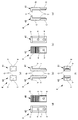
- FIG. 1 It is a three-plane figure which shows the hand tool which concerns on embodiment, (a) is a top view, (b) is a front view, (c) is a side view. (A) is an enlarged view which shows the closed state of a clamping part, (b) is an enlarged view which shows the open state of a clamping part. It is a three-plane figure which shows the state by which the 1st carbon member, the 2nd carbon member, and the axial part were assembled, (a) is a top view, (b) is a front view, (c) is a side view. is there.
- FIG. 1 is a three-view diagram illustrating a hand tool 100 according to an embodiment
- FIG. 1 (a) is a plan view
- FIG. 1 (b) is a front view
- FIG. 1 (c) is a side view.
- FIG. 2A is an enlarged view showing a closed state of the clamping unit 2
- FIG. 2B is an enlarged view showing an opened state of the clamping unit 2.
- the back view of the hand tool 100 is omitted because it is the same as the front view.
- the hand tool 100 is, for example, a pliers, a wrench, a wrench, a nipper, a pliers, etc. that are used by a user by gripping with hands.
- the hand tool 100 used as a pliers will be described as an example.
- the hand tool 100 includes a gripping portion 1 and a clamping portion 2 that swings around the shaft portion 3 in conjunction with the gripping portion 1.
- the user usually operates by holding the grip portion 1 with his / her hand to change from the closed state shown in FIG. 2 (a) to the open state shown in FIG. 2 (b) or shown in FIG. 2 (b).
- the clamping part 2 is swung and operated from the open state to the closed state shown in FIG.
- the sandwiching portion 2 includes sandwiching jaws 12 and 22 made of a carbon reinforced composite material (made of carbon) and a steel attachment 4 that can be attached to and detached from the sandwiching jaws 12 and 22.
- the carbon reinforced composite material may be, for example, a carbon fiber reinforced resin (CFRP) in which carbon fibers are impregnated with an epoxy resin or the like.
- CFRP carbon fiber reinforced resin
- the attachment 4 is detachably fixed to the clamping jaws 12 and 22 by bolts or the like (not shown) penetrating through the mounting holes d provided in the clamping jaws 12 and 22.
- the attachment 4 is detachable, even if the portion that comes into contact with the sandwiched body is damaged, it is possible to return to the hand tool 100 that exhibits the same function as a new product by simply replacing the attachment 4.
- the multifunctional hand tool 100 can be realized by exchanging the attachment 4 with the attachment 4 having a different function while sharing the lightweight grip 1 and the clamping jaws 12 and 22.
- the hand tool 100 can be made lighter than the entire clamping unit 2 made of steel, and the weight balance can be improved without the center of gravity being too biased toward the gripping unit 1.
- the hand tool 100 includes a first carbon member 10 having a first gripping part 11 and a first clamping jaw 12, a second carbon member 20 having a second gripping part 21 and a second clamping jaw 22, A shaft portion 3 that pivotally supports the first carbon member 10 and the second carbon member 20 and an attachment 4 that is detachable with respect to the first clamping jaw 12 and the second clamping jaw 22 are provided.
- the first carbon member 10 and the second carbon member 20 have the same shape, and are combined so that they are pivotally supported by the shaft portion 3 and swingable about the shaft portion 3 with the front and back sides being reversed. Has been.
- FIG. 3 is a three-plane view showing a state in which the first carbon member 10, the second carbon member 20, and the shaft portion 3 are assembled
- FIG. 3 (a) is a plan view
- FIG. 3 (b) is a front view
- FIG. 3C is a side view.
- the first carbon member 10 and the second carbon member 20 are assembled via the shaft portion 3.
- the first carbon member 10 and the second carbon member 20 are made of a carbon reinforced composite material and are lighter than those made of steel. That is, the 1st holding part 11, the 2nd holding part 21, the 1st clamping jaw 12, and the 2nd clamping jaw 22 are a product made from a carbon reinforcement composite material.
- the attachment 4 which is the other part of the clamping part 2 is made of steel.
- part of the gripping portion 1 is also made of carbon reinforced composite material, so that the weight can be reduced and the center of gravity is on the gripping portion 1 side.
- the weight balance can be improved without being too biased.
- first clamping jaw 12 and the second clamping jaw 22 have a bulging portion B that bulges in a swinging direction that is a swinging direction about the shaft portion 3.
- the 1st clamping jaw 12 and the 2nd clamping jaw 22 have the bulging part B, even if a to-be-clamped body is pinched strongly by the clamping part 2 which has the attachment 4, the 1st clamping jaw 12 and the 2nd clamping jaw
- the shear stress acting on 22 can be dispersed and relaxed, and even if the first clamping jaw 12 and the second clamping jaw 22 are made of a carbon reinforced composite material, damage can be avoided.
- the 1st clamping jaw 12 and the 2nd clamping jaw 22 may have the reinforcement rib R which protrudes in the axial direction of the axial part 3. As shown in FIG. As a result, as in the case of having the bulging portion B, even if the sandwiched body 2 is strongly sandwiched by the sandwiching portion 2 having the attachment 4, the shear stress acting on the first sandwiching jaw 12 and the second sandwiching jaw 22 is dispersed. Even if the first clamping jaw 12 and the second clamping jaw 22 are made of a carbon reinforced composite material, damage can be avoided. In addition, the 1st clamping jaw 12 and the 2nd clamping jaw 22 may have both the bulging part B and the reinforcement rib R, in order to improve a reinforcement effect further.
- the first clamping jaw 12 and the second clamping jaw 22 each have a slot S in a shape into which the engagement block T (see FIG. 4) of the attachment 4 is fitted. Thereby, the attachment 4 can be reliably positioned with respect to the first clamping jaw 12 and the second clamping jaw 22.
- the shaft portion 3 includes a first washer 31 (washer) made of gun metal fixed to the first carbon member 10, and a second washer 32 fixed to the second carbon member 20.
- the shaft 33 penetrates the first washer 31 and the second washer 32.
- the second washer 32 may be made of gun metal, steel, other metal or resin.
- the shaft 33 is made of steel, for example.
- the first washer 31 and the second washer 32 are annular thin plates having a center hole, and a shaft 33 is passed through the center hole.
- the 1st washer 31 and the 2nd washer 32 have a seat surface which is orthogonal to the rotating shaft of the axial part 3, respectively, and mutually faces and is in surface contact.
- the seating surface of the first washer 31 and the seating surface of the second washer 32 slide as the first carbon member 10 and the second carbon member 20 swing.
- the shaft portion 3 since the shaft portion 3 has the first washer 31 made of gunmetal, the shaft portion 3 can be prevented from being corroded, and the friction increases due to the progress of corrosion, so that the rotational resistance around the shaft portion 3 is reduced. It can be prevented from becoming large.
- FIG. 4 is a six-sided view showing the attachment 4, FIG. 4 (a) is a plan view, FIG. 4 (b) is a front view, and FIG. 4 (c) is a right side view. (D) is a left side view, FIG. 4 (e) is a rear view, and FIG. 4 (f) is a bottom view.
- 4 (a) to 4 (f) are a combination of the six-sided view of the first attachment 41 and the six-sided view of the second attachment 42, and FIGS. 4 (a) to 4 (f).
- Each of the drawings shows the second attachment 42 on the left side and the first attachment 41 on the right side.
- the attachment 4 includes a first attachment 41 and a second attachment 42.
- the 1st attachment 41 and the 2nd attachment 42 are the shapes into which right and left were reversed.
- the first attachment 41 has a shape in which the L shape of the alphabet is turned upside down in front view
- the second attachment 42 has a shape relative to the shape of the first attachment 41. The shape is reversed left and right.
- Each of the first attachment 41 and the second attachment 42 has a cutter part C having a sharp tip.
- the cutter unit C is positioned so that the tips are in contact with each other in a state of facing each other, and is attached to the clamping unit 2.
- the attachment 4 comes into contact with the first attachment 41 and the second attachment 42 facing each other, and has an alphabetical T shape in front view.
- the attachment 4 since the attachment 4 has the cutter part C, it can be set as the hand tool 100 which has the function to cut
- the 1st attachment 41 and the 2nd attachment 42 have the engagement block T which can be engaged with the slot S (refer FIG. 3) of the 1st clamping jaw 12 and the 2nd clamping jaw 22, respectively.
- the attachment 4 can be reliably positioned with respect to the first clamping jaw 12 and the second clamping jaw 22.
- the first attachment 41 and the second attachment 42 have a screw hole e into which a bolt or the like (not shown) that passes through the mounting hole d (see FIG. 3) is screwed.
- the first attachment 41 and the second attachment 42 are configured so that the first clamping jaw 12 and the second attachment 42 are in a state where the engagement block T is engaged with the slot S (see FIG. 3) of the first clamping jaw 12 and the second clamping jaw 22. It is detachably fixed to the second clamping jaw 22.
- the attachment 4 is not limited to a bolt or the like as long as it is detachable.
- the first attachment 41 and the second attachment 42 have cover portions V that cover the tips of the clamping jaws 12 and 22, respectively.
- the tips of the sandwich jaws 12 and 22 made of carbon reinforced composite material that are easily damaged by an action such as impact or shear force can be covered with the steel attachment 4 that is not easily damaged. It can suppress that the clamping part 2 including it breaks.
- the first attachment 41 and the second attachment 42 each have a grip portion G provided with unevenness for increasing the grip force when the sandwiched body is sandwiched. Thereby, a to-be-clamped body can be clamped firmly.
- a hand tool 100 according to the present invention is a hand tool 100 that includes a gripping portion 1 and a clamping portion 2 that swings around a shaft portion 3 in conjunction with the gripping portion 1.
- the sandwiching part 2 has sandwiching jaws 12 and 22 made of carbon-reinforced composite material, and a steel attachment 4 that is detachable with respect to the sandwiching jaws 12 and 22. Since the bulging portion B bulges in the swinging direction, even if the clamping jaws 12 and 22 that are part of the clamping portion 2 are made of a reinforced composite material, the shear stress acting on the clamping jaws 12 and 22 is dispersed. Even if the clamping jaws 12 and 22 are made of a carbon reinforced composite material, damage to the clamping part 2 can be avoided. Therefore, the hand tool 100 can be made lighter than the entire clamping unit 2 made of steel, and the weight balance can be improved without the center of gravity being too biased toward the gripping unit 1.
- a hand tool 100 according to the present invention is a hand tool 100 that includes a gripping portion 1 and a clamping portion 2 that swings around a shaft portion 3 in conjunction with the gripping portion 1.
- the sandwiching part 2 has sandwiching jaws 12 and 22 made of carbon-reinforced composite material, and a steel attachment 4 that is detachable with respect to the sandwiching jaws 12 and 22. Since the reinforcing ribs R project in the axial direction of the shaft portion 3 are provided, even if the sandwiching jaws 12 and 22 that are part of the sandwiching portion 2 are made of reinforced composite material, the shear stress acting on the sandwiching jaws 12 and 22 is exerted.
- the hand tool 100 can be made lighter than the entire clamping unit 2 made of steel, and the weight balance can be improved without the center of gravity being too biased toward the gripping unit 1.
Landscapes
- Engineering & Computer Science (AREA)
- Mechanical Engineering (AREA)
- Gripping Jigs, Holding Jigs, And Positioning Jigs (AREA)
Abstract
軽量な手工具を提供する。本発明の手工具100は、把持部1と、把持部1に連動して軸部3を中心として揺動する挟持部2とを備える手工具100であって、把持部1は、炭素強化複合材製であり、挟持部2は、炭素強化複合材製の挟持顎12、22と、挟持顎12、22に対して着脱自在な鋼製のアタッチメント4を有し、挟持顎12、22は、軸部3の軸方向に突出する補強リブRを有する。挟持顎12、22は、軸部3の軸方向に突出する補強リブRを有する。
Description
本発明は、手工具に関する。
従来、作業部を除く柄部を炭素繊維強化樹脂によって形成した作業工具がある(例えば、特許文献1参照)。
しかしながら、従来の作業工具は、柄部を軽量としているものの、作業部を金属製としているため、重心が作業部側に偏っており、依然として重量感のあるものであった。
本発明は、上述のような課題に鑑みなされたものであり、軽量な手工具を提供することを目的とする。
本発明は、上記目的を達成するために、以下の構成によって把握される。
(1)本発明の手工具は、把持部と、前記把持部に連動して軸部を中心として揺動する挟持部とを備える手工具であって、前記把持部は、炭素強化複合材製であり、前記挟持部は、炭素強化複合材製の挟持顎と、前記挟持顎に対して着脱自在な鋼製のアタッチメントを有し、前記挟持顎は、揺動方向に膨出する膨出部を有する。
(2)本発明の手工具は、把持部と、前記把持部に連動して軸部を中心として揺動する挟持部とを備える手工具であって、前記把持部は、炭素強化複合材製であり、前記挟持部は、炭素強化複合材製の挟持顎と、前記挟持顎に対して着脱自在な鋼製のアタッチメントを有し、前記挟持顎は、前記軸部の軸方向に突出する補強リブを有する。
(3)上記(1)又は(2)の構成において、前記軸部は、砲金製の座金を有する。
(4)上記(1)から(3)のいずれかの構成において、前記アタッチメントは、前記挟持顎の先端を覆う。
本発明によれば、軽量な手工具を提供できる。
(実施形態)
以下、本発明を実施するための形態(以下、「実施形態」という。)を、添付図面に基づいて詳細に説明する。
以下、本発明を実施するための形態(以下、「実施形態」という。)を、添付図面に基づいて詳細に説明する。
図1は、実施形態に係る手工具100を示す三面図であり、図1(a)は平面図であり、図1(b)は正面図であり、図1(c)は側面図である。図2(a)は挟持部2の閉状態を示す拡大図であり、図2(b)は挟持部2の開状態を示す拡大図である。なお、図1において、手工具100の背面図は、正面図と同様であるため、省略されている。
手工具100は、例えば、ペンチ、レンチ、スパナ、ニッパ、プライヤ等、ユーザが手で把持して使用するものである。以下では、ペンチとして使用する手工具100を例にして説明する。
図1に示すように、手工具100は、把持部1と、把持部1に連動して軸部3を中心として揺動する挟持部2とを備える。ユーザは、通常、把持部1を手で把持した状態で操作することで、図2(a)に示す閉状態から図2(b)に示す開状態へ、又は、図2(b)に示す開状態から図2(a)に示す閉状態へと挟持部2を揺動させて動作させる。
挟持部2は、炭素強化複合材製(カーボン製)の挟持顎12、22と、挟持顎12、22に対して着脱自在な鋼製のアタッチメント4を有する。なお、炭素強化複合材は、例えば、炭素繊維をエポキシ樹脂等に含侵させた炭素繊維強化樹脂(CFRP)であってよい。
アタッチメント4は、挟持顎12、22に設けられた取付穴dを貫通するボルト等(不図示)により、挟持顎12、22に対して着脱自在に固定される。
これにより、比較的靭性及びせん断強度が乏しく破損しやすい炭素強化複合材製の部分を直接的に被挟持体と接触させることなく、鋼製部材を介して被挟持体と接触させることができる。よって、耐久性が高く、しかも、軽量な手工具100を実現できる。また、アタッチメント4は着脱自在であるので、被挟持体と接触する部分が破損しても、アタッチメント4を交換するだけで、新品同様の機能を発揮する手工具100に戻したりできる。加えて、軽量な把持部1及び挟持顎12、22を共有したまま、アタッチメント4を異なる機能のアタッチメント4に交換して、多機能な手工具100を実現できる。さらに、挟持部2の全体を鋼製にするのに比べて、手工具100を軽量にできる上に、重心が把持部1側に偏りすぎずに、重量バランスを良くできる。
手工具100は、詳細には、第1把持部11及び第1挟持顎12を有する第1カーボン部材10と、第2把持部21及び第2挟持顎22を有する第2カーボン部材20と、第1カーボン部材10及び第2カーボン部材20を軸支する軸部3と、第1挟持顎12及び第2挟持顎22に対して着脱自在なアタッチメント4とを備える。第1カーボン部材10と第2カーボン部材20とは、同じ形状であり、互いに表裏を逆にした状態で、軸部3に軸支されて軸部3を中心に揺動自在になるように組み合わされている。
そして、第1カーボン部材10と第2カーボン部材20とが組み合わされた状態で、第1カーボン部材10の第1把持部11と第2カーボン部材20の第2把持部21とが把持部1を構成する。また、第1カーボン部材10と第2カーボン部材20とが組み合わされた状態で、第1カーボン部材10の第1挟持顎12と第2カーボン部材20の第2挟持顎22とアタッチメント4とが挟持部2を構成する。
そして、第1カーボン部材10と第2カーボン部材20とが組み合わされた状態で、第1カーボン部材10の第1把持部11と第2カーボン部材20の第2把持部21とが把持部1を構成する。また、第1カーボン部材10と第2カーボン部材20とが組み合わされた状態で、第1カーボン部材10の第1挟持顎12と第2カーボン部材20の第2挟持顎22とアタッチメント4とが挟持部2を構成する。
(第1カーボン部材10及び第2カーボン部材20)
次に、第1カーボン部材10及び第2カーボン部材20について詳細に説明する。
図3は、第1カーボン部材10と第2カーボン部材20と軸部3とが組み立てられた状態を示す三面図であり、図3(a)は平面図であり、図3(b)は正面図であり、図3(c)は側面図である。
次に、第1カーボン部材10及び第2カーボン部材20について詳細に説明する。
図3は、第1カーボン部材10と第2カーボン部材20と軸部3とが組み立てられた状態を示す三面図であり、図3(a)は平面図であり、図3(b)は正面図であり、図3(c)は側面図である。
図3(a)、図3(b)及び図3(c)に示すように、第1カーボン部材10及び第2カーボン部材20は、軸部3を介して組み立てられる。
第1カーボン部材10及び第2カーボン部材20は、炭素強化複合材製であり、鋼製のものよりも軽量となっている。すなわち、第1把持部11、第2把持部21、第1挟持顎12及び第2挟持顎22は炭素強化複合材製である。一方、挟持部2の他部であるアタッチメント4は鋼製である。これにより、挟持部2の全てが炭素強化複合材製であるのに加えて、把持部1の一部も炭素強化複合材製であるので、軽量にできる上に、重心が把持部1側に偏りすぎずに、重量バランスを良くできる。
第1カーボン部材10及び第2カーボン部材20は、炭素強化複合材製であり、鋼製のものよりも軽量となっている。すなわち、第1把持部11、第2把持部21、第1挟持顎12及び第2挟持顎22は炭素強化複合材製である。一方、挟持部2の他部であるアタッチメント4は鋼製である。これにより、挟持部2の全てが炭素強化複合材製であるのに加えて、把持部1の一部も炭素強化複合材製であるので、軽量にできる上に、重心が把持部1側に偏りすぎずに、重量バランスを良くできる。
また、第1挟持顎12及び第2挟持顎22は、軸部3を中心として揺動する方向である揺動方向に膨出する膨出部Bを有する。このように、第1挟持顎12及び第2挟持顎22は膨出部Bを有するので、アタッチメント4を有する挟持部2によって被挟持体を強く挟んでも、第1挟持顎12及び第2挟持顎22に作用するせん断応力を分散させて緩和でき、第1挟持顎12及び第2挟持顎22が炭素強化複合材製であっても、破損を免れることができる。
ところで、第1挟持顎12及び第2挟持顎22は、軸部3の軸方向に突出する補強リブRを有してもよい。これにより、膨出部Bを有する場合と同様に、アタッチメント4を有する挟持部2によって被挟持体を強く挟んでも、第1挟持顎12及び第2挟持顎22に作用するせん断応力を分散させて低減でき、第1挟持顎12及び第2挟持顎22が炭素強化複合材製であっても、破損を免れることができる。なお、第1挟持顎12及び第2挟持顎22は、補強効果を更に高めるため、膨出部Bと補強リブRとを両方有してもよい。
第1挟持顎12及び第2挟持顎22は、それぞれ、アタッチメント4の係合ブロックT(図4参照)が嵌る形状のスロットSを有する。これにより、アタッチメント4を第1挟持顎12及び第2挟持顎22に対して、確実に位置決めできる。
(軸部3)
次に、軸部3について詳細に説明する。
図1から図3に示すように、軸部3は、第1カーボン部材10に固定される砲金製の第1座金31(座金)と、第2カーボン部材20に固定される第2座金32と、第1座金31及び第2座金32を貫通する軸33を備える。なお、第2座金32は、砲金製であっても、鋼製であっても、その他の金属製又は樹脂製であってもよい。軸33は、例えば、鋼製である。
第1座金31及び第2座金32は、円環状の薄板であり、中心孔を有し、その中心孔には軸33が貫通されている。
また、第1座金31及び第2座金32は、それぞれ、軸部3の回転軸と直交し、互いが対向して面接触する座面を有する。そして、第1座金31の座面及び第2座金32の座面は、第1カーボン部材10及び第2カーボン部材20の揺動に伴い摺動する。
このように、軸部3は、砲金製の第1座金31を有するので、軸部3が腐食するのを抑制でき、腐食の進行によって摩擦が増加して軸部3を中心とする回転抵抗が大きくなるのを防ぐことができる。
(アタッチメント4)
次に、アタッチメント4について詳細に説明する。
図4は、アタッチメント4を示す六面図であり、図4(a)は平面図であり、図4(b)は正面図であり、図4(c)は右側面図であり、図4(d)は左側面図であり、図4(e)は背面図であり、図4(f)は底面図である。なお、図4(a)~図4(f)は、第1アタッチメント41の六面図と第2アタッチメント42の六面図を合わせたものであり、図4(a)~図4(f)の各図は、第2アタッチメント42を左側に、第1アタッチメント41を右側に示している。
次に、アタッチメント4について詳細に説明する。
図4は、アタッチメント4を示す六面図であり、図4(a)は平面図であり、図4(b)は正面図であり、図4(c)は右側面図であり、図4(d)は左側面図であり、図4(e)は背面図であり、図4(f)は底面図である。なお、図4(a)~図4(f)は、第1アタッチメント41の六面図と第2アタッチメント42の六面図を合わせたものであり、図4(a)~図4(f)の各図は、第2アタッチメント42を左側に、第1アタッチメント41を右側に示している。
図4に示すように、アタッチメント4は、第1アタッチメント41と、第2アタッチメント42とを有する。
第1アタッチメント41と、第2アタッチメント42とは、左右が反転した形状である。
第1アタッチメント41は、図4(b)に示すように、正面視において、アルファベットのL字を上下逆にした形状になっており、第2アタッチメント42は、第1アタッチメント41の形状に対して左右が反転した形状となっている。
第1アタッチメント41と、第2アタッチメント42とは、左右が反転した形状である。
第1アタッチメント41は、図4(b)に示すように、正面視において、アルファベットのL字を上下逆にした形状になっており、第2アタッチメント42は、第1アタッチメント41の形状に対して左右が反転した形状となっている。
第1アタッチメント41及び第2アタッチメント42は、それぞれ、先端が鋭利なカッタ部Cを有する。カッタ部Cは、図1に示すように、互いに向かい合った状態で、先端同士が当接するように位置決めされて、挟持部2に対して取り付けられる。この状態において、アタッチメント4は、第1アタッチメント41と第2アタッチメント42とが互いに向き合った状態で当接し、正面視においてアルファベットのT字状になる。
このように、アタッチメント4はカッタ部Cを有するので、ペンチのように、被挟持体をしっかりと挟持する機能に加えて、ワイヤを切断する機能を有する手工具100とすることができる。
このように、アタッチメント4はカッタ部Cを有するので、ペンチのように、被挟持体をしっかりと挟持する機能に加えて、ワイヤを切断する機能を有する手工具100とすることができる。
また、第1アタッチメント41及び第2アタッチメント42は、それぞれ、第1挟持顎12及び第2挟持顎22のスロットS(図3参照)に係合可能な係合ブロックTを有する。
これにより、アタッチメント4を第1挟持顎12及び第2挟持顎22に対して、確実に位置決めできる。
これにより、アタッチメント4を第1挟持顎12及び第2挟持顎22に対して、確実に位置決めできる。
第1アタッチメント41及び第2アタッチメント42は、取付穴d(図3参照)を貫通するボルト等(不図示)が螺合するネジ穴eを有する。そして、第1アタッチメント41及び第2アタッチメント42は、係合ブロックTが第1挟持顎12及び第2挟持顎22のスロットS(図3参照)に係合した状態で、第1挟持顎12及び第2挟持顎22に対して着脱自在に固定される。なお、アタッチメント4の固定は、着脱自在であれば、ボルト等によるものに限らない。
第1アタッチメント41及び第2アタッチメント42は、それぞれ、挟持顎12、22の先端を覆うカバー部Vを有する。これにより、衝撃やせん断力等の作用によって破損しやすい炭素強化複合材製の挟持顎12、22の先端を、破損しにくい鋼製のアタッチメント4で覆うことができるので、挟持顎12、22を含む挟持部2が破損するのを抑制できる。
第1アタッチメント41及び第2アタッチメント42は、それぞれ、被挟持体を挟む際にグリップ力を増すための凹凸が設けられたグリップ部Gを有する。これにより、被挟持体をしっかりと挟むことができる。
以上、実施形態を用いて本発明を説明したが、本発明の技術的範囲は上記実施形態に記載の範囲には限定されないことは言うまでもない。上記実施形態に、多様な変更又は改良を加えることが可能であることが当業者に明らかである。また、そのような変更又は改良を加えた形態も本発明の技術的範囲に含まれ得ることが、特許請求の範囲の記載から明らかである。
本発明の手工具100は、把持部1と、把持部1に連動して軸部3を中心として揺動する挟持部2とを備える手工具100であって、把持部1は、炭素強化複合材製であり、挟持部2は、炭素強化複合材製の挟持顎12、22と、挟持顎12、22に対して着脱自在な鋼製のアタッチメント4を有し、挟持顎12、22は、揺動方向に膨出する膨出部Bを有するので、挟持部2の一部である挟持顎12、22が強化複合材製であっても、挟持顎12、22に作用するせん断応力を分散させて緩和でき、挟持顎12、22が炭素強化複合材製であっても、挟持部2の破損を免れることができる。よって、挟持部2の全体を鋼製にするのに比べて、手工具100を軽量にできる上に、重心が把持部1側に偏りすぎずに、重量バランスを良くできる。
本発明の手工具100は、把持部1と、把持部1に連動して軸部3を中心として揺動する挟持部2とを備える手工具100であって、把持部1は、炭素強化複合材製であり、挟持部2は、炭素強化複合材製の挟持顎12、22と、挟持顎12、22に対して着脱自在な鋼製のアタッチメント4を有し、挟持顎12、22は、軸部3の軸方向に突出する補強リブRを有するので、挟持部2の一部である挟持顎12、22が強化複合材製であっても、挟持顎12、22に作用するせん断応力を分散させて緩和でき、挟持顎12、22が炭素強化複合材製であっても、挟持部2の破損を免れることができる。よって、挟持部2の全体を鋼製にするのに比べて、手工具100を軽量にできる上に、重心が把持部1側に偏りすぎずに、重量バランスを良くできる。
1 把持部
2 挟持部
3 軸部
4 アタッチメント
10 第1カーボン部材
11 第1把持部
12 第1挟持顎
20 第2カーボン部材
21 第2把持部
22 第2挟持顎
31 第1座金
32 第2座金
33 軸
41 第1アタッチメント
42 第2アタッチメント
100 手工具
B 膨出部
C カッタ部
d 取付穴
e ネジ穴
G グリップ部
R 補強リブ
S スロット
T 係合ブロック
V カバー部
2 挟持部
3 軸部
4 アタッチメント
10 第1カーボン部材
11 第1把持部
12 第1挟持顎
20 第2カーボン部材
21 第2把持部
22 第2挟持顎
31 第1座金
32 第2座金
33 軸
41 第1アタッチメント
42 第2アタッチメント
100 手工具
B 膨出部
C カッタ部
d 取付穴
e ネジ穴
G グリップ部
R 補強リブ
S スロット
T 係合ブロック
V カバー部
Claims (4)
- 把持部と、前記把持部に連動して軸部を中心として揺動する挟持部とを備える手工具であって、
前記把持部は、炭素強化複合材製であり、
前記挟持部は、炭素強化複合材製の挟持顎と、前記挟持顎に対して着脱自在な鋼製のアタッチメントを有し、
前記挟持顎は、揺動方向に膨出する膨出部を有する
ことを特徴とする手工具。 - 把持部と、前記把持部に連動して軸部を中心として揺動する挟持部とを備える手工具であって、
前記把持部は、炭素強化複合材製であり、
前記挟持部は、炭素強化複合材製の挟持顎と、前記挟持顎に対して着脱自在な鋼製のアタッチメントを有し、
前記挟持顎は、前記軸部の軸方向に突出する補強リブを有する
ことを特徴とする手工具。 - 前記軸部は、砲金製の座金を有する
ことを特徴とする請求項1又は請求項2に記載の手工具。 - 前記アタッチメントは、前記挟持顎の先端を覆う
ことを特徴とする請求項1から請求項3のいずれか1項に記載の手工具。
Applications Claiming Priority (2)
| Application Number | Priority Date | Filing Date | Title |
|---|---|---|---|
| JP2018-038006 | 2018-03-02 | ||
| JP2018038006A JP2019150920A (ja) | 2018-03-02 | 2018-03-02 | 手工具 |
Publications (1)
| Publication Number | Publication Date |
|---|---|
| WO2019167529A1 true WO2019167529A1 (ja) | 2019-09-06 |
Family
ID=67805748
Family Applications (1)
| Application Number | Title | Priority Date | Filing Date |
|---|---|---|---|
| PCT/JP2019/003215 Ceased WO2019167529A1 (ja) | 2018-03-02 | 2019-01-30 | 手工具 |
Country Status (2)
| Country | Link |
|---|---|
| JP (1) | JP2019150920A (ja) |
| WO (1) | WO2019167529A1 (ja) |
Cited By (1)
| Publication number | Priority date | Publication date | Assignee | Title |
|---|---|---|---|---|
| EP4197702A1 (de) | 2021-12-17 | 2023-06-21 | maurerfreund GmbH | Handwerkzeug mit griff |
Citations (6)
| Publication number | Priority date | Publication date | Assignee | Title |
|---|---|---|---|---|
| JPS598782U (ja) * | 1982-07-09 | 1984-01-20 | 東レ株式会社 | 作業工具 |
| DE19910838A1 (de) * | 1999-03-11 | 2000-09-14 | Rennsteig Werkzeuge Gmbh | Zange zum Verpressen von Hülsenverbindern |
| US20040133989A1 (en) * | 2003-01-13 | 2004-07-15 | The Stanley Works | Tool with inserted blade members |
| JP2016140154A (ja) * | 2015-01-26 | 2016-08-04 | 弘満 土屋 | 線材加工用工具 |
| JP2017007081A (ja) * | 2015-06-16 | 2017-01-12 | ハン キム、イル | 捩れ防止工具用プライヤ |
| JP2017109263A (ja) * | 2015-12-15 | 2017-06-22 | 株式会社東日製作所 | スパナのヘッド構造、スパナおよびヘッド構造の製造方法 |
-
2018
- 2018-03-02 JP JP2018038006A patent/JP2019150920A/ja active Pending
-
2019
- 2019-01-30 WO PCT/JP2019/003215 patent/WO2019167529A1/ja not_active Ceased
Patent Citations (6)
| Publication number | Priority date | Publication date | Assignee | Title |
|---|---|---|---|---|
| JPS598782U (ja) * | 1982-07-09 | 1984-01-20 | 東レ株式会社 | 作業工具 |
| DE19910838A1 (de) * | 1999-03-11 | 2000-09-14 | Rennsteig Werkzeuge Gmbh | Zange zum Verpressen von Hülsenverbindern |
| US20040133989A1 (en) * | 2003-01-13 | 2004-07-15 | The Stanley Works | Tool with inserted blade members |
| JP2016140154A (ja) * | 2015-01-26 | 2016-08-04 | 弘満 土屋 | 線材加工用工具 |
| JP2017007081A (ja) * | 2015-06-16 | 2017-01-12 | ハン キム、イル | 捩れ防止工具用プライヤ |
| JP2017109263A (ja) * | 2015-12-15 | 2017-06-22 | 株式会社東日製作所 | スパナのヘッド構造、スパナおよびヘッド構造の製造方法 |
Cited By (1)
| Publication number | Priority date | Publication date | Assignee | Title |
|---|---|---|---|---|
| EP4197702A1 (de) | 2021-12-17 | 2023-06-21 | maurerfreund GmbH | Handwerkzeug mit griff |
Also Published As
| Publication number | Publication date |
|---|---|
| JP2019150920A (ja) | 2019-09-12 |
Similar Documents
| Publication | Publication Date | Title |
|---|---|---|
| JP2013116054A (ja) | 携帯型作業機 | |
| US20040155229A1 (en) | Pry Bar Handle | |
| US20160039078A1 (en) | Hammer | |
| US7346991B1 (en) | Hand tool providing double compound leverage to the jaws | |
| US5197194A (en) | Shears with removable blades | |
| WO2019167529A1 (ja) | 手工具 | |
| CA3206710A1 (en) | Combination hand tool having a hammer, a hatchet, and two types of screw and nail pullers | |
| KR101538943B1 (ko) | 비틀림이 적은 광범위 스플릿링 플라이어 | |
| US1334965A (en) | Jawed tool | |
| US8671806B2 (en) | Wrench/tool system with separate handle and interchangeable wrench/tool ends | |
| US2801468A (en) | Metal-cutting shears | |
| US7913400B2 (en) | Compact bolt cutter with improved mechanical advantage | |
| JP6764215B2 (ja) | 理髪用鋏 | |
| US3129737A (en) | Hammer with detachable head | |
| US1685217A (en) | Garden tool | |
| JP3153103U (ja) | 頭髪用レザー | |
| US7526865B2 (en) | Utility knife with rear gyre pivot structure | |
| US20040139616A1 (en) | Snips with removable blades | |
| TWI556920B (zh) | Universal clamp switch structure | |
| US20230249329A1 (en) | Adapter tool with multiple attachments | |
| US1008088A (en) | Hay-knife. | |
| JP2005279801A (ja) | プライヤー | |
| US4869482A (en) | Tool for loosening a seized ball joint in a motor vehicle | |
| US20130104704A1 (en) | Handheld work machine | |
| US299488A (en) | moeeell |
Legal Events
| Date | Code | Title | Description |
|---|---|---|---|
| 121 | Ep: the epo has been informed by wipo that ep was designated in this application |
Ref document number: 19760540 Country of ref document: EP Kind code of ref document: A1 |
|
| NENP | Non-entry into the national phase |
Ref country code: DE |
|
| 122 | Ep: pct application non-entry in european phase |
Ref document number: 19760540 Country of ref document: EP Kind code of ref document: A1 |