WO2019167529A1 - Outil à main - Google Patents
Outil à main Download PDFInfo
- Publication number
- WO2019167529A1 WO2019167529A1 PCT/JP2019/003215 JP2019003215W WO2019167529A1 WO 2019167529 A1 WO2019167529 A1 WO 2019167529A1 JP 2019003215 W JP2019003215 W JP 2019003215W WO 2019167529 A1 WO2019167529 A1 WO 2019167529A1
- Authority
- WO
- WIPO (PCT)
- Prior art keywords
- attachment
- clamping
- hand tool
- clamping jaw
- carbon
- Prior art date
- Legal status (The legal status is an assumption and is not a legal conclusion. Google has not performed a legal analysis and makes no representation as to the accuracy of the status listed.)
- Ceased
Links
Images


Classifications
-
- B—PERFORMING OPERATIONS; TRANSPORTING
- B25—HAND TOOLS; PORTABLE POWER-DRIVEN TOOLS; MANIPULATORS
- B25B—TOOLS OR BENCH DEVICES NOT OTHERWISE PROVIDED FOR, FOR FASTENING, CONNECTING, DISENGAGING OR HOLDING
- B25B7/00—Pliers; Other hand-held gripping tools with jaws on pivoted limbs; Details applicable generally to pivoted-limb hand tools
- B25B7/02—Jaws
-
- B—PERFORMING OPERATIONS; TRANSPORTING
- B25—HAND TOOLS; PORTABLE POWER-DRIVEN TOOLS; MANIPULATORS
- B25B—TOOLS OR BENCH DEVICES NOT OTHERWISE PROVIDED FOR, FOR FASTENING, CONNECTING, DISENGAGING OR HOLDING
- B25B7/00—Pliers; Other hand-held gripping tools with jaws on pivoted limbs; Details applicable generally to pivoted-limb hand tools
- B25B7/06—Joints
Definitions
- the present invention relates to a hand tool.
- the conventional work tool has a light handle part
- the work part is made of metal, so the center of gravity is biased toward the work part side, and it still has a heavy feeling.
- the present invention has been made in view of the above-described problems, and an object thereof is to provide a lightweight hand tool.
- the present invention is grasped by the following composition in order to achieve the above-mentioned object.
- the hand tool of the present invention is a hand tool including a grip portion and a sandwiching portion that swings around a shaft portion in conjunction with the grip portion, and the grip portion is made of a carbon reinforced composite material.
- the sandwiching portion has a sandwiching jaw made of carbon-reinforced composite material and a steel attachment that is detachable from the sandwiching jaw, and the sandwiching jaw bulges in a swinging direction.
- the hand tool of the present invention is a hand tool including a grip portion and a sandwiching portion that swings around a shaft portion in conjunction with the grip portion, and the grip portion is made of a carbon reinforced composite material.
- the sandwiching part has a sandwiching jaw made of a carbon reinforced composite material and a steel attachment detachably attached to the sandwiching jaw, and the sandwiching jaw is a reinforcement projecting in the axial direction of the shaft part.
- the shaft portion has a gun metal washer.
- the attachment covers the tip of the clamping jaw.
- a lightweight hand tool can be provided.
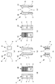
- FIG. 1 It is a three-plane figure which shows the hand tool which concerns on embodiment, (a) is a top view, (b) is a front view, (c) is a side view. (A) is an enlarged view which shows the closed state of a clamping part, (b) is an enlarged view which shows the open state of a clamping part. It is a three-plane figure which shows the state by which the 1st carbon member, the 2nd carbon member, and the axial part were assembled, (a) is a top view, (b) is a front view, (c) is a side view. is there.
- FIG. 1 is a three-view diagram illustrating a hand tool 100 according to an embodiment
- FIG. 1 (a) is a plan view
- FIG. 1 (b) is a front view
- FIG. 1 (c) is a side view.
- FIG. 2A is an enlarged view showing a closed state of the clamping unit 2
- FIG. 2B is an enlarged view showing an opened state of the clamping unit 2.
- the back view of the hand tool 100 is omitted because it is the same as the front view.
- the hand tool 100 is, for example, a pliers, a wrench, a wrench, a nipper, a pliers, etc. that are used by a user by gripping with hands.
- the hand tool 100 used as a pliers will be described as an example.
- the hand tool 100 includes a gripping portion 1 and a clamping portion 2 that swings around the shaft portion 3 in conjunction with the gripping portion 1.
- the user usually operates by holding the grip portion 1 with his / her hand to change from the closed state shown in FIG. 2 (a) to the open state shown in FIG. 2 (b) or shown in FIG. 2 (b).
- the clamping part 2 is swung and operated from the open state to the closed state shown in FIG.
- the sandwiching portion 2 includes sandwiching jaws 12 and 22 made of a carbon reinforced composite material (made of carbon) and a steel attachment 4 that can be attached to and detached from the sandwiching jaws 12 and 22.
- the carbon reinforced composite material may be, for example, a carbon fiber reinforced resin (CFRP) in which carbon fibers are impregnated with an epoxy resin or the like.
- CFRP carbon fiber reinforced resin
- the attachment 4 is detachably fixed to the clamping jaws 12 and 22 by bolts or the like (not shown) penetrating through the mounting holes d provided in the clamping jaws 12 and 22.
- the attachment 4 is detachable, even if the portion that comes into contact with the sandwiched body is damaged, it is possible to return to the hand tool 100 that exhibits the same function as a new product by simply replacing the attachment 4.
- the multifunctional hand tool 100 can be realized by exchanging the attachment 4 with the attachment 4 having a different function while sharing the lightweight grip 1 and the clamping jaws 12 and 22.
- the hand tool 100 can be made lighter than the entire clamping unit 2 made of steel, and the weight balance can be improved without the center of gravity being too biased toward the gripping unit 1.
- the hand tool 100 includes a first carbon member 10 having a first gripping part 11 and a first clamping jaw 12, a second carbon member 20 having a second gripping part 21 and a second clamping jaw 22, A shaft portion 3 that pivotally supports the first carbon member 10 and the second carbon member 20 and an attachment 4 that is detachable with respect to the first clamping jaw 12 and the second clamping jaw 22 are provided.
- the first carbon member 10 and the second carbon member 20 have the same shape, and are combined so that they are pivotally supported by the shaft portion 3 and swingable about the shaft portion 3 with the front and back sides being reversed. Has been.
- FIG. 3 is a three-plane view showing a state in which the first carbon member 10, the second carbon member 20, and the shaft portion 3 are assembled
- FIG. 3 (a) is a plan view
- FIG. 3 (b) is a front view
- FIG. 3C is a side view.
- the first carbon member 10 and the second carbon member 20 are assembled via the shaft portion 3.
- the first carbon member 10 and the second carbon member 20 are made of a carbon reinforced composite material and are lighter than those made of steel. That is, the 1st holding part 11, the 2nd holding part 21, the 1st clamping jaw 12, and the 2nd clamping jaw 22 are a product made from a carbon reinforcement composite material.
- the attachment 4 which is the other part of the clamping part 2 is made of steel.
- part of the gripping portion 1 is also made of carbon reinforced composite material, so that the weight can be reduced and the center of gravity is on the gripping portion 1 side.
- the weight balance can be improved without being too biased.
- first clamping jaw 12 and the second clamping jaw 22 have a bulging portion B that bulges in a swinging direction that is a swinging direction about the shaft portion 3.
- the 1st clamping jaw 12 and the 2nd clamping jaw 22 have the bulging part B, even if a to-be-clamped body is pinched strongly by the clamping part 2 which has the attachment 4, the 1st clamping jaw 12 and the 2nd clamping jaw
- the shear stress acting on 22 can be dispersed and relaxed, and even if the first clamping jaw 12 and the second clamping jaw 22 are made of a carbon reinforced composite material, damage can be avoided.
- the 1st clamping jaw 12 and the 2nd clamping jaw 22 may have the reinforcement rib R which protrudes in the axial direction of the axial part 3. As shown in FIG. As a result, as in the case of having the bulging portion B, even if the sandwiched body 2 is strongly sandwiched by the sandwiching portion 2 having the attachment 4, the shear stress acting on the first sandwiching jaw 12 and the second sandwiching jaw 22 is dispersed. Even if the first clamping jaw 12 and the second clamping jaw 22 are made of a carbon reinforced composite material, damage can be avoided. In addition, the 1st clamping jaw 12 and the 2nd clamping jaw 22 may have both the bulging part B and the reinforcement rib R, in order to improve a reinforcement effect further.
- the first clamping jaw 12 and the second clamping jaw 22 each have a slot S in a shape into which the engagement block T (see FIG. 4) of the attachment 4 is fitted. Thereby, the attachment 4 can be reliably positioned with respect to the first clamping jaw 12 and the second clamping jaw 22.
- the shaft portion 3 includes a first washer 31 (washer) made of gun metal fixed to the first carbon member 10, and a second washer 32 fixed to the second carbon member 20.
- the shaft 33 penetrates the first washer 31 and the second washer 32.
- the second washer 32 may be made of gun metal, steel, other metal or resin.
- the shaft 33 is made of steel, for example.
- the first washer 31 and the second washer 32 are annular thin plates having a center hole, and a shaft 33 is passed through the center hole.
- the 1st washer 31 and the 2nd washer 32 have a seat surface which is orthogonal to the rotating shaft of the axial part 3, respectively, and mutually faces and is in surface contact.
- the seating surface of the first washer 31 and the seating surface of the second washer 32 slide as the first carbon member 10 and the second carbon member 20 swing.
- the shaft portion 3 since the shaft portion 3 has the first washer 31 made of gunmetal, the shaft portion 3 can be prevented from being corroded, and the friction increases due to the progress of corrosion, so that the rotational resistance around the shaft portion 3 is reduced. It can be prevented from becoming large.
- FIG. 4 is a six-sided view showing the attachment 4, FIG. 4 (a) is a plan view, FIG. 4 (b) is a front view, and FIG. 4 (c) is a right side view. (D) is a left side view, FIG. 4 (e) is a rear view, and FIG. 4 (f) is a bottom view.
- 4 (a) to 4 (f) are a combination of the six-sided view of the first attachment 41 and the six-sided view of the second attachment 42, and FIGS. 4 (a) to 4 (f).
- Each of the drawings shows the second attachment 42 on the left side and the first attachment 41 on the right side.
- the attachment 4 includes a first attachment 41 and a second attachment 42.
- the 1st attachment 41 and the 2nd attachment 42 are the shapes into which right and left were reversed.
- the first attachment 41 has a shape in which the L shape of the alphabet is turned upside down in front view
- the second attachment 42 has a shape relative to the shape of the first attachment 41. The shape is reversed left and right.
- Each of the first attachment 41 and the second attachment 42 has a cutter part C having a sharp tip.
- the cutter unit C is positioned so that the tips are in contact with each other in a state of facing each other, and is attached to the clamping unit 2.
- the attachment 4 comes into contact with the first attachment 41 and the second attachment 42 facing each other, and has an alphabetical T shape in front view.
- the attachment 4 since the attachment 4 has the cutter part C, it can be set as the hand tool 100 which has the function to cut
- the 1st attachment 41 and the 2nd attachment 42 have the engagement block T which can be engaged with the slot S (refer FIG. 3) of the 1st clamping jaw 12 and the 2nd clamping jaw 22, respectively.
- the attachment 4 can be reliably positioned with respect to the first clamping jaw 12 and the second clamping jaw 22.
- the first attachment 41 and the second attachment 42 have a screw hole e into which a bolt or the like (not shown) that passes through the mounting hole d (see FIG. 3) is screwed.
- the first attachment 41 and the second attachment 42 are configured so that the first clamping jaw 12 and the second attachment 42 are in a state where the engagement block T is engaged with the slot S (see FIG. 3) of the first clamping jaw 12 and the second clamping jaw 22. It is detachably fixed to the second clamping jaw 22.
- the attachment 4 is not limited to a bolt or the like as long as it is detachable.
- the first attachment 41 and the second attachment 42 have cover portions V that cover the tips of the clamping jaws 12 and 22, respectively.
- the tips of the sandwich jaws 12 and 22 made of carbon reinforced composite material that are easily damaged by an action such as impact or shear force can be covered with the steel attachment 4 that is not easily damaged. It can suppress that the clamping part 2 including it breaks.
- the first attachment 41 and the second attachment 42 each have a grip portion G provided with unevenness for increasing the grip force when the sandwiched body is sandwiched. Thereby, a to-be-clamped body can be clamped firmly.
- a hand tool 100 according to the present invention is a hand tool 100 that includes a gripping portion 1 and a clamping portion 2 that swings around a shaft portion 3 in conjunction with the gripping portion 1.
- the sandwiching part 2 has sandwiching jaws 12 and 22 made of carbon-reinforced composite material, and a steel attachment 4 that is detachable with respect to the sandwiching jaws 12 and 22. Since the bulging portion B bulges in the swinging direction, even if the clamping jaws 12 and 22 that are part of the clamping portion 2 are made of a reinforced composite material, the shear stress acting on the clamping jaws 12 and 22 is dispersed. Even if the clamping jaws 12 and 22 are made of a carbon reinforced composite material, damage to the clamping part 2 can be avoided. Therefore, the hand tool 100 can be made lighter than the entire clamping unit 2 made of steel, and the weight balance can be improved without the center of gravity being too biased toward the gripping unit 1.
- a hand tool 100 according to the present invention is a hand tool 100 that includes a gripping portion 1 and a clamping portion 2 that swings around a shaft portion 3 in conjunction with the gripping portion 1.
- the sandwiching part 2 has sandwiching jaws 12 and 22 made of carbon-reinforced composite material, and a steel attachment 4 that is detachable with respect to the sandwiching jaws 12 and 22. Since the reinforcing ribs R project in the axial direction of the shaft portion 3 are provided, even if the sandwiching jaws 12 and 22 that are part of the sandwiching portion 2 are made of reinforced composite material, the shear stress acting on the sandwiching jaws 12 and 22 is exerted.
- the hand tool 100 can be made lighter than the entire clamping unit 2 made of steel, and the weight balance can be improved without the center of gravity being too biased toward the gripping unit 1.
Landscapes
- Engineering & Computer Science (AREA)
- Mechanical Engineering (AREA)
- Gripping Jigs, Holding Jigs, And Positioning Jigs (AREA)
Abstract
L'invention concerne un outil à main léger. L'outil à main (100) selon l'invention est pourvu d'une partie poignée (1) et d'une partie de préhension (2) qui pivote autour d'une partie arbre (3) en coordination avec la partie poignée (1). La partie poignée (1) est formée à partir d'un matériau composite renforcé de carbone. La partie de préhension (2) comporte des mâchoires de préhension (12, 22) formées à partir d'un matériau composite renforcé de carbone, ainsi qu'une fixation (4) formée à partir d'acier et pouvant être montée amovible sur les mâchoires de préhension (12, 22). Les mâchoires de préhension (12, 22) comportent des nervures de renfort (R) faisant saillie dans le sens axial de la partie arbre (3).
Applications Claiming Priority (2)
| Application Number | Priority Date | Filing Date | Title |
|---|---|---|---|
| JP2018-038006 | 2018-03-02 | ||
| JP2018038006A JP2019150920A (ja) | 2018-03-02 | 2018-03-02 | 手工具 |
Publications (1)
| Publication Number | Publication Date |
|---|---|
| WO2019167529A1 true WO2019167529A1 (fr) | 2019-09-06 |
Family
ID=67805748
Family Applications (1)
| Application Number | Title | Priority Date | Filing Date |
|---|---|---|---|
| PCT/JP2019/003215 Ceased WO2019167529A1 (fr) | 2018-03-02 | 2019-01-30 | Outil à main |
Country Status (2)
| Country | Link |
|---|---|
| JP (1) | JP2019150920A (fr) |
| WO (1) | WO2019167529A1 (fr) |
Cited By (1)
| Publication number | Priority date | Publication date | Assignee | Title |
|---|---|---|---|---|
| EP4197702A1 (fr) | 2021-12-17 | 2023-06-21 | maurerfreund GmbH | Outil manuel pourvu de manche |
Citations (6)
| Publication number | Priority date | Publication date | Assignee | Title |
|---|---|---|---|---|
| JPS598782U (ja) * | 1982-07-09 | 1984-01-20 | 東レ株式会社 | 作業工具 |
| DE19910838A1 (de) * | 1999-03-11 | 2000-09-14 | Rennsteig Werkzeuge Gmbh | Zange zum Verpressen von Hülsenverbindern |
| US20040133989A1 (en) * | 2003-01-13 | 2004-07-15 | The Stanley Works | Tool with inserted blade members |
| JP2016140154A (ja) * | 2015-01-26 | 2016-08-04 | 弘満 土屋 | 線材加工用工具 |
| JP2017007081A (ja) * | 2015-06-16 | 2017-01-12 | ハン キム、イル | 捩れ防止工具用プライヤ |
| JP2017109263A (ja) * | 2015-12-15 | 2017-06-22 | 株式会社東日製作所 | スパナのヘッド構造、スパナおよびヘッド構造の製造方法 |
-
2018
- 2018-03-02 JP JP2018038006A patent/JP2019150920A/ja active Pending
-
2019
- 2019-01-30 WO PCT/JP2019/003215 patent/WO2019167529A1/fr not_active Ceased
Patent Citations (6)
| Publication number | Priority date | Publication date | Assignee | Title |
|---|---|---|---|---|
| JPS598782U (ja) * | 1982-07-09 | 1984-01-20 | 東レ株式会社 | 作業工具 |
| DE19910838A1 (de) * | 1999-03-11 | 2000-09-14 | Rennsteig Werkzeuge Gmbh | Zange zum Verpressen von Hülsenverbindern |
| US20040133989A1 (en) * | 2003-01-13 | 2004-07-15 | The Stanley Works | Tool with inserted blade members |
| JP2016140154A (ja) * | 2015-01-26 | 2016-08-04 | 弘満 土屋 | 線材加工用工具 |
| JP2017007081A (ja) * | 2015-06-16 | 2017-01-12 | ハン キム、イル | 捩れ防止工具用プライヤ |
| JP2017109263A (ja) * | 2015-12-15 | 2017-06-22 | 株式会社東日製作所 | スパナのヘッド構造、スパナおよびヘッド構造の製造方法 |
Cited By (1)
| Publication number | Priority date | Publication date | Assignee | Title |
|---|---|---|---|---|
| EP4197702A1 (fr) | 2021-12-17 | 2023-06-21 | maurerfreund GmbH | Outil manuel pourvu de manche |
Also Published As
| Publication number | Publication date |
|---|---|
| JP2019150920A (ja) | 2019-09-12 |
Similar Documents
| Publication | Publication Date | Title |
|---|---|---|
| JP2013116054A (ja) | 携帯型作業機 | |
| US20040155229A1 (en) | Pry Bar Handle | |
| US20160039078A1 (en) | Hammer | |
| US7346991B1 (en) | Hand tool providing double compound leverage to the jaws | |
| US5197194A (en) | Shears with removable blades | |
| WO2019167529A1 (fr) | Outil à main | |
| CA3206710A1 (fr) | Outil a main combine comprenant un marteau, une hachette et deux types d~arrache-vis et d~arrache-clous | |
| KR101538943B1 (ko) | 비틀림이 적은 광범위 스플릿링 플라이어 | |
| US1334965A (en) | Jawed tool | |
| US8671806B2 (en) | Wrench/tool system with separate handle and interchangeable wrench/tool ends | |
| US2801468A (en) | Metal-cutting shears | |
| US7913400B2 (en) | Compact bolt cutter with improved mechanical advantage | |
| JP6764215B2 (ja) | 理髪用鋏 | |
| US3129737A (en) | Hammer with detachable head | |
| US1685217A (en) | Garden tool | |
| JP3153103U (ja) | 頭髪用レザー | |
| US7526865B2 (en) | Utility knife with rear gyre pivot structure | |
| US20040139616A1 (en) | Snips with removable blades | |
| TWI556920B (zh) | Universal clamp switch structure | |
| US20230249329A1 (en) | Adapter tool with multiple attachments | |
| US1008088A (en) | Hay-knife. | |
| JP2005279801A (ja) | プライヤー | |
| US4869482A (en) | Tool for loosening a seized ball joint in a motor vehicle | |
| US20130104704A1 (en) | Handheld work machine | |
| US299488A (en) | moeeell |
Legal Events
| Date | Code | Title | Description |
|---|---|---|---|
| 121 | Ep: the epo has been informed by wipo that ep was designated in this application |
Ref document number: 19760540 Country of ref document: EP Kind code of ref document: A1 |
|
| NENP | Non-entry into the national phase |
Ref country code: DE |
|
| 122 | Ep: pct application non-entry in european phase |
Ref document number: 19760540 Country of ref document: EP Kind code of ref document: A1 |