WO2019167607A1 - カメラモジュール - Google Patents
カメラモジュール Download PDFInfo
- Publication number
- WO2019167607A1 WO2019167607A1 PCT/JP2019/004932 JP2019004932W WO2019167607A1 WO 2019167607 A1 WO2019167607 A1 WO 2019167607A1 JP 2019004932 W JP2019004932 W JP 2019004932W WO 2019167607 A1 WO2019167607 A1 WO 2019167607A1
- Authority
- WO
- WIPO (PCT)
- Prior art keywords
- lens
- camera module
- support component
- opening
- light
- Prior art date
- Legal status (The legal status is an assumption and is not a legal conclusion. Google has not performed a legal analysis and makes no representation as to the accuracy of the status listed.)
- Ceased
Links
Images


Classifications
-
- G—PHYSICS
- G02—OPTICS
- G02B—OPTICAL ELEMENTS, SYSTEMS OR APPARATUS
- G02B7/00—Mountings, adjusting means, or light-tight connections, for optical elements
- G02B7/02—Mountings, adjusting means, or light-tight connections, for optical elements for lenses
-
- G—PHYSICS
- G03—PHOTOGRAPHY; CINEMATOGRAPHY; ANALOGOUS TECHNIQUES USING WAVES OTHER THAN OPTICAL WAVES; ELECTROGRAPHY; HOLOGRAPHY
- G03B—APPARATUS OR ARRANGEMENTS FOR TAKING PHOTOGRAPHS OR FOR PROJECTING OR VIEWING THEM; APPARATUS OR ARRANGEMENTS EMPLOYING ANALOGOUS TECHNIQUES USING WAVES OTHER THAN OPTICAL WAVES; ACCESSORIES THEREFOR
- G03B17/00—Details of cameras or camera bodies; Accessories therefor
- G03B17/02—Bodies
-
- G—PHYSICS
- G02—OPTICS
- G02B—OPTICAL ELEMENTS, SYSTEMS OR APPARATUS
- G02B1/00—Optical elements characterised by the material of which they are made; Optical coatings for optical elements
- G02B1/10—Optical coatings produced by application to, or surface treatment of, optical elements
- G02B1/11—Anti-reflection coatings
-
- G—PHYSICS
- G02—OPTICS
- G02B—OPTICAL ELEMENTS, SYSTEMS OR APPARATUS
- G02B13/00—Optical objectives specially designed for the purposes specified below
- G02B13/001—Miniaturised objectives for electronic devices, e.g. portable telephones, webcams, PDAs, small digital cameras
-
- G—PHYSICS
- G02—OPTICS
- G02B—OPTICAL ELEMENTS, SYSTEMS OR APPARATUS
- G02B5/00—Optical elements other than lenses
- G02B5/20—Filters
- G02B5/208—Filters for use with infrared or ultraviolet radiation, e.g. for separating visible light from infrared and/or ultraviolet radiation
-
- H—ELECTRICITY
- H04—ELECTRIC COMMUNICATION TECHNIQUE
- H04N—PICTORIAL COMMUNICATION, e.g. TELEVISION
- H04N23/00—Cameras or camera modules comprising electronic image sensors; Control thereof
- H04N23/50—Constructional details
- H04N23/55—Optical parts specially adapted for electronic image sensors; Mounting thereof
-
- H—ELECTRICITY
- H04—ELECTRIC COMMUNICATION TECHNIQUE
- H04N—PICTORIAL COMMUNICATION, e.g. TELEVISION
- H04N23/00—Cameras or camera modules comprising electronic image sensors; Control thereof
- H04N23/57—Mechanical or electrical details of cameras or camera modules specially adapted for being embedded in other devices
-
- G—PHYSICS
- G03—PHOTOGRAPHY; CINEMATOGRAPHY; ANALOGOUS TECHNIQUES USING WAVES OTHER THAN OPTICAL WAVES; ELECTROGRAPHY; HOLOGRAPHY
- G03B—APPARATUS OR ARRANGEMENTS FOR TAKING PHOTOGRAPHS OR FOR PROJECTING OR VIEWING THEM; APPARATUS OR ARRANGEMENTS EMPLOYING ANALOGOUS TECHNIQUES USING WAVES OTHER THAN OPTICAL WAVES; ACCESSORIES THEREFOR
- G03B2205/00—Adjustment of optical system relative to image or object surface other than for focusing
- G03B2205/0053—Driving means for the movement of one or more optical element
- G03B2205/0069—Driving means for the movement of one or more optical element using electromagnetic actuators, e.g. voice coils
Definitions
- This technology relates to a camera module, and in particular, to a camera module that enables the camera module to be reduced in height.
- Patent Document 1 describes a technique for reducing or preventing the occurrence of ghosts in a camera module.
- an opening for allowing light from a lens to pass is provided in a support part that supports IRCF (Infra Red Cut Cut Off Filter), and light that has passed through the opening. Is incident on the image sensor.
- IRCF Infra Red Cut Cut Off Filter
- This technology has been made in view of such a situation, and makes it possible to reduce the height of a camera module.
- the camera module of the present technology has an opening through which the light from a lens that collects light passes, and is disposed so as to cover the opening between the lens and an image sensor that photoelectrically converts the light.
- a support part that supports the optical component on the image sensor side, and a slope part that is inclined in a thickness direction of the support part is provided around the opening, and the support part is provided with the slope part.
- the lens is disposed so that the lens and the lens face each other, and a portion of the lens facing the support component is a second surface of the support component opposite to the first surface on which the optical component is disposed.
- the camera module is configured to be disposed closer to the first surface than the surface.
- the support component includes an opening through which the light from a lens that collects light passes, and the opening is provided between the lens and an image sensor that photoelectrically converts the light.
- An optical component arranged so as to cover is supported on the image sensor side.
- a gradient portion that is inclined in the thickness direction of the support component is provided around the opening, and the support component is disposed so that the inclination of the gradient portion and the lens face each other.
- the portion of the lens that faces the support component is disposed closer to the first surface than the second surface of the support component opposite to the first surface on which the optical component is disposed. .
- the camera module can be reduced in height.
- FIG. 3 is a plan view illustrating a configuration example of an imaging unit 130 in FIG. 2. It is sectional drawing which compares the camera module 10 and the camera module 110.
- FIG. FIG. 6 is a cross-sectional view illustrating a first configuration example of a gradient portion.
- FIG. 6 is a cross-sectional view for explaining the inclination of the first configuration example of the gradient portion.
- FIG. 6 is a cross-sectional view illustrating a second configuration example of a gradient portion 134.
- FIG. 6 is a cross-sectional view illustrating an example of the relationship between the inclination of a gradient portion and a lens 121.
- FIG. 12 is a cross-sectional view illustrating another example of the relationship between the inclination of the gradient portion 134 and the lens 121.
- FIG. It is sectional drawing explaining the example of the relationship between the inclination of the gradient part 134, and the lens 121 in case the gradient part 134 inclines continuously. It is sectional drawing which shows the 3rd structural example of the gradient part. It is sectional drawing which shows the 4th structural example of the gradient part. It is sectional drawing which shows the example of adhesion
- FIG. 1 is a cross-sectional view showing a configuration example of a camera module.
- 1 has a lens unit 20 and an imaging unit 30.
- the lens unit 20 includes a lens 21, a lens barrel (barrel) 22, a lens holder 23, a coil 24, a spring 25, an actuator unit 26, and a magnet 27.
- the imaging unit 30 includes a substrate 31, a support component 32, an IRCF 35, an imaging element 36, and a mounting component 38.
- the lens 21 is incorporated in a lens barrel 22, and the lens barrel 22 is held by a lens holder 23.
- the lens holder 23 is supported in the actuator unit 26 by a spring 25 so that the lens holder 23 can move in the vertical direction in the figure.
- the focus is adjusted by moving the lens holder 23 in the vertical direction.
- All of the cross-sectional views of the camera module of the present specification are cross-sectional views at the “macro mechanical end” state in which the lens 21 is in the lowest direction (image sensor side).
- a coil 24 is provided on the side surface of the lens holder 23.
- a magnet 27 is provided at a position facing the coil 24 of the actuator unit 26.
- the lens unit 20 (the actuator unit 26 thereof) is a support component in a state where the optical axis of the lens 21 and the center of the effective pixel 37 of the image sensor 36 are aligned directly above the image sensor 36 provided on the substrate 31. It is bonded on the top 32 with an adhesive 28.
- the support component 32 has an opening 33 through which light from the lens 21 passes, directly above the image sensor 36 (the effective pixel 37).
- a gradient portion 34 that is inclined in the thickness direction of the support component 32 is provided, and the support component 32 is disposed so that the inclination of the gradient portion 34 and the imaging device 36 face each other. Yes.
- the support component 32 is configured to have a height at which the IRCF 35 can be fixed at an appropriate height from the image sensor 36, and is bonded to the substrate 31 with an adhesive 40.
- an opening lower portion 33D a portion of the opening 33 of the support component 32 on the side facing the imaging element 36 is referred to as an opening lower portion 33D
- a portion of the opening 33 of the support component 32 on the side facing the lens 21 is referred to as an opening upper portion 33U. .
- the IRCF 35 is bonded to the lower surface of the support component 32 (the surface facing the imaging device 36) with an adhesive or the like so as to cover the opening 33 of the support component 32.
- the image sensor 36 is provided on the substrate 31 and is electrically connected to the substrate 31 by a gold wire (wire) 39.
- the mounting component 38 is, for example, a capacitor, a resistor, or an electronic component such as an IC (Integrated Circuit), and is disposed at a predetermined position on the substrate 31 and is electrically connected.
- IC Integrated Circuit
- the lens 21 condenses light, and the light passes through the opening 33 and is further irradiated to the image sensor 36 via the IRCF 35.
- the image sensor 36 the light irradiated to the image sensor 36 is photoelectrically converted in the effective pixels 37, and thereby an image is captured.
- the slope of the slope portion 34 is provided so as to face the image sensor 36.
- the lens 21 has an opening at the (lowermost) portion (the portion facing the support component 32) of the lens 21 so that the (tilted) tip of the gradient portion 34 and the lens 21 do not interfere with each other. It is arranged so as to be the same as or slightly above the upper portion 33U.
- the lens 21 In the camera module 10, it is necessary to arrange the lens 21 so that the inclination does not interfere with the tip of the gradient portion 34 provided so as to face the image sensor 36, and the lens 21 is positioned below the upper opening portion 33U. It is difficult to lower. Therefore, it is difficult to reduce the height of the camera module 10.
- the camera module 10 in order to prevent the tip of the gradient portion 34 and the lens 21 (lower portion) from interfering with each other, it is necessary to form the opening upper portion 33U of the opening portion 33 to a certain size. . Therefore, it is difficult to reduce the size of the opening 33 provided in the support component 32.
- the light from the lens 21 that has passed through the opening 33 is incident on a portion other than the effective pixel 37 of the image sensor 36, for example, the gold wire 39, and the incident light is reflected by the gold wire 39.
- the gold wire 39 there is a high possibility that ghosts and flares (gold wire ghosts and flares) due to the reflection of light at the gold wire 39 occur.
- the slope of the slope portion 34 is provided so as to face the image sensor 36, so that the size of the opening lower portion 33 ⁇ / b> D of the opening portion 33 is necessarily larger than the size of the opening upper portion 33 ⁇ / b> U. Become. Therefore, the size of the IRCF 35 disposed on the lower surface of the support component 32 so as to cover the opening 33 is increased, and the cost of the camera module 10 is increased by the increase in the size of the IRCF 35.
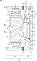
- FIG. 2 is a cross-sectional view showing a configuration example of the first embodiment of the camera module to which the present technology is applied.
- the camera module 110 shown in FIG. 2 includes a lens unit 120 and an imaging unit 130.
- the lens unit 120 includes a lens 121, a lens barrel (barrel) 122, a lens holder 123, a coil 124, a spring 125, an actuator unit 126, and a magnet 127.
- the imaging unit 130 includes a substrate 131, a support component 132, an IRCF 135, an imaging element 136, and a mounting component 138.
- the lens 121, the lens barrel 122, the lens holder 123, the coil 124, the spring 125, the actuator unit 126, and the magnet 127 of the lens unit 120 are the lens 21, lens barrel 22, and lens 127 of the lens unit 20 shown in FIG. It corresponds to the lens holder 23, the coil 24, the spring 25, the actuator unit 26, and the magnet 27, respectively.
- the substrate 131, the support component 132, the IRCF 135, the image sensor 136, and the mounting component 138 of the imaging unit 130 are the substrate 31, the support component 32, the IRCF 35, the image sensor 36, and the mounting component 138 shown in FIG. Each corresponds to the mounting component 38.
- the support component 132 has an opening 133 through which light from the lens 121 passes immediately above the image pickup element 136 (its effective pixel 137).
- a slope portion 134 that is inclined in the thickness direction of the support component 132 is provided, and the support component 132 is disposed so that the slope of the slope portion 134 and the lens 121 face each other. . Therefore, the support component 132 is larger than the support component 32 arranged so that the inclination of the gradient portion 34 faces the image sensor 36 in that the inclination of the gradient portion 134 faces the lens 121.
- the support component 132 is configured to have a height at which the IRCF 135 can be fixed at an appropriate height from the image sensor 136, and is bonded to the substrate 131 with the adhesive 140.
- the tip of the gradient portion 34 is located on the upper surface (surface facing the lens 21) side of the support component 32, whereas in the camera module 110, the lower side of the support component 132
- the tip of the gradient portion 134 is located on the surface (first surface) side. That is, in the camera module 110, the tip of the gradient part 134 is positioned below the tip of the gradient part 34 of the camera module 10. Therefore, in the camera module 110, the lens 121 can be disposed below the lens 21 of the camera module 10.
- a portion of the opening 133 of the support component 132 on the side facing the imaging element 136 is referred to as an opening lower portion 133D
- a portion of the opening 133 of the support component 132 on the side facing the lens 121 is referred to as an opening upper portion 133U. .
- the lens 121 can be disposed below the lens 21 if the upper opening 133U is larger than the upper opening 33U. That is, in the camera module 110, the lower portion of the lens 121 (the portion facing the support component 132) is positioned on the lower surface side of the upper surface (second surface) opposite to the lower surface of the support component 132. Can be arranged. In FIG. 2, the lens 121 is disposed so that the lower portion of the lens 121 is positioned between the upper opening portion 133U (second surface) and the lower opening portion 133D (first surface).
- a transparent plate-like optical component such as a transparent cover film or a transparent cover glass is used instead of the IRCF 135, for example.
- the optical component can be used and supported by the support component 132.
- the focus can be adjusted by moving the lens holder 123 in the vertical direction, but the lens holder 123 can be fixed to the imaging unit 130 so as not to move in the vertical direction.
- the camera module 110 can be configured without providing the spring 125, the actuator unit 126, and the magnet 127.
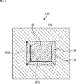
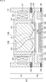
- FIG. 3 is a plan view showing a configuration example of the imaging unit 130 of FIG.
- a substantially rectangular opening 133 is formed at the center of the substantially rectangular support part 132 as viewed from above.
- a slope portion 134 that is inclined in the thickness direction of the support component 132 is provided.
- the slope 134 is formed on the upper surface (surface facing the lens 121) side of the support component 132.
- the IRCF 135 is disposed on the support component 132 by adhering to the lower surface of the support component 132 (the surface facing the image sensor 136) so as to cover (close) the opening 133.
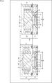
- FIG. 4 is a cross-sectional view comparing the camera module 10 and the camera module 110.
- the tip of the gradient part 134 exists below (the image sensor 136 side) than the tip of the gradient part 34 of the camera module 10.
- the tip of the gradient portion 134 is larger than the distance between the tip of the gradient portion 34 and the lens 21.
- the distance between the lens 121 and the lens 121 increases. Therefore, the camera module 110 is less likely to interfere with the tip of the gradient portion 134 and the lens 121 than the camera module 10.
- the slope of the slope portion 134 is formed on the upper surface (surface facing the lens 121) side of the support component 132, which inevitably increases the size of the opening upper portion 133 U of the opening 133. This is larger than the size A2 of the lower opening 133D.
- the size A2 of the lower opening 133D is smaller than the size of the upper opening 133U.
- the size A2 of the opening lower portion 133D of the module 110 is smaller than the size A1 of the opening upper portion 33U of the camera module 10. Therefore, the size of the opening 133 of the camera module 110 can be made smaller than the size of the opening 33 of the camera module 10.
- the IRCF 35 and the IRCF 135 are arranged on the lower surfaces of the support component 32 and the support component 132 so as to cover the opening 33 and the opening 133, respectively, in the camera module 10, the size of the opening lower portion 33D is larger.
- the IRCF 35 having a large size B1 is required, and the IRCF 135 having a size B2 larger than the size A2 of the lower opening 133D is required in the camera module 110.
- the slope of the slope portion 34 is formed on the lower surface (the surface facing the image sensor 36) of the support component 32, so that the size of the opening lower portion 33 ⁇ / b> D of the opening 33 is inevitably increased. This is larger than the size A1 of the upper opening 33U.
- the size of the lower opening 33D is larger than the size A1 of the upper opening 33U, and therefore the lower opening 133D of the camera module 110. Is larger than A2. That is, the size A2 of the opening lower portion 133D is smaller than the size of the opening lower portion 33D. Therefore, the size B2 of the IRCF 135 arranged so as to cover the lower opening 133D can be made smaller than the size B1 of the IRCF 35 arranged so as to cover the lower opening 33D.
- the lens 121 when the lens 121 is disposed at the same position (height) as the lens 21, the lens 121 is less likely to interfere with the tip of the gradient portion 134 and the lens 121. 121 can be disposed at a position lower than the lens 21 toward the image sensor 136.
- the height C2 of the lens unit 120 of the camera module 110 can be made lower than the height C1 of the lens unit 20 of the camera module 10, and as a result, the overall height (total height) of the lens unit 120 can be reduced. The height of the camera module 110 can be reduced.
- the camera module 110 is reduced in height. It can be realized more effectively.
- the gradient portion 134 can be configured to have a reflection control structure that restricts reflection of light from the lens 121.
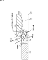
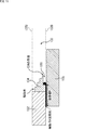
- FIG. 5 is a cross-sectional view showing a first configuration example of the gradient portion 134.
- the gradient part 134 (inclination) of the camera module 110 is configured in a step-like structure as a reflection control structure.
- the gradient portion 134 is configured in a step shape, so that the light incident on the gradient portion 134 from the lens 121 can be obtained more than when the gradient portion 134 is continuously (smoothly) inclined.
- the incident angle is increased, and light incident on the gradient portion 134 from the lens 121 is easily reflected toward the outside of the lens 121. Therefore, it is possible to suppress the light reflected by the gradient portion 134 from returning (reflecting toward the lens 121), and as a result, it is possible to suppress ghost and flare generated by the light reflected by the gradient portion 134. it can.
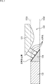
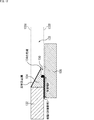
- FIG. 6 is a cross-sectional view illustrating the inclination of the first configuration example of the gradient portion 134.
- the inclination angle of the gradient part 134 with respect to the optical axis of the lens 121 is larger than the angle of the light incident from the lens 121 to the tip of the gradient part 134 with respect to the optical axis of the lens 121 (light incident angle). It can be constituted as follows.
- the incident angle of light incident from the lens 121 to the tip of the gradient portion 134 is 38 degrees
- the inclination angle of the gradient portion 134 with respect to the optical axis of the lens 121 (hereinafter also referred to as the inclination angle) is , which is 60 degrees larger than 38 degrees.
- the stepped portion (standing wall) of the gradient portion 134 (Vertical part) is lowered. Therefore, it is possible to suppress the light reflected by the step board portion (horizontal portion) of the staircase portion 134 from being further reflected by the stepped portion of the staircase. Thereby, generation
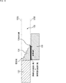
- FIG. 7 is a cross-sectional view showing a second configuration example of the gradient portion 134.
- the gradient portion 134 of the camera module 110 has a structure in which an antireflection film for preventing light reflection is formed on the gradient portion 134 as a reflection control structure.
- the antireflection film can be formed, for example, by applying an antireflection agent or attaching an antireflection sheet.
- the slope portion 134 is continuously inclined.
- the slope portion 134 is configured in a step shape as shown in FIG. 5, and the antireflection film is formed on the step-like slope portion 134. Can be formed.
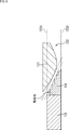
- FIG. 8 is a cross-sectional view for explaining an example of the relationship between the inclination of the gradient portion 134 and the lens 121.
- the inclination of the slope part 134 can be configured in a linear shape substantially parallel to the tangent of the surface of the lower part of the lens 121 (the part facing the support component 132) in cross-sectional view.
- the lens 121 when the slope of the slope portion 134 is configured in a shape substantially parallel to the tangent to the surface of the lower portion of the lens 121, the lens 121 can be further disposed on the lower side (the image sensor 136 side). It can. Thereby, the overall height of the lens unit 120 can be further reduced, and as a result, the camera module 110 can be further reduced in height.
- the gradient part 134 is comprised in step shape, the gradient part 134 can be comprised so that it may incline continuously, for example, as shown in FIG.
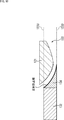
- FIG. 9 is a cross-sectional view for explaining another example of the relationship between the inclination of the gradient portion 134 and the lens 121.
- the slope of the slope part 134 can be configured in a curved shape (non-linear shape) substantially parallel to the surface of the lower part of the lens 121 (the part facing the support component 132) in cross-sectional view.
- the lens 121 when the slope of the slope portion 134 is configured in a shape substantially parallel to the surface of the lower portion of the lens 121, the lens 121 can be further disposed on the lower side. Thereby, the overall height of the lens unit 120 can be further reduced, and as a result, the camera module 110 can be further reduced in height.
- the gradient part 134 is comprised by step shape, the gradient part 134 can be comprised so that it may incline continuously, for example, as shown in FIG.
- FIG. 10 is a cross-sectional view illustrating an example of a relationship between the inclination of the gradient portion 134 and the lens 121 when the gradient portion 134 is continuously inclined.
- the gradient portion 134 is configured to be continuously inclined, and the inclination of the gradient portion 134 is substantially the same as the surface of the lower portion of the lens 121 (the portion facing the support component 132) in a cross-sectional view.
- the curved shape is formed in parallel.
- an antireflection film is formed on the gradient portion 134.
- the lens 121 when the slope of the slope portion 134 is configured in a shape substantially parallel to the surface of the lower portion of the lens 121, the lens 121 can be further disposed on the lower side. Thereby, the overall height of the lens unit 120 can be further reduced, and as a result, the camera module 110 can be further reduced in height.
- FIG. 11 is a cross-sectional view showing a third configuration example of the gradient portion 134.
- the slope portion 134 is configured in a staircase shape as in FIG. 5.
- the slope portion 134 is provided with a resin reservoir 150 which is a groove recessed from the tip of the slope portion 134 on the lower surface side of the support component 132.
- the IRCF 135 is bonded to the lower surface of the support component 132 with a predetermined bonding width W.
- a resin such as a UV (Ultra Violet) adhesive can be employed.
- the IRCF 135 when the resin reservoir 150 is provided in the gradient portion 134, when the IRCF 135 is bonded to the lower surface of the support component 132 with the UV adhesive, the IRCF 135 is disposed on the resin reservoir 150 side.
- the protruding UV adhesive can be stored in the resin reservoir 150. Therefore, it is possible to prevent the UV adhesive from protruding from the tip of the gradient portion 134 of the support component 132.
- FIG. 12 is a cross-sectional view showing a fourth configuration example of the gradient portion 134.
- FIG. 12 similarly to the case of FIG. 11, it is possible to suppress ghosts and flares that are generated when light is reflected by the UV adhesive.
- thermoplastic resin or a thermosetting resin can be employed in addition to the UV adhesive.
- thermoplastic resin or thermosetting resin as the adhesive, a black thermoplastic resin or thermosetting resin can be employed.
- thermoplastic resin or a thermosetting resin When a black thermoplastic resin or a thermosetting resin is used as the adhesive for bonding the IRCF 135 to the support component 132, the thermoplastic resin or the thermosetting resin that protrudes from the bonding portion between the support component 132 and the IRCF 135. Therefore, it is not always necessary to provide the resin reservoir 150 at the tip of the gradient portion 134 as shown in FIGS.
- the gradient portion 134 can be configured without providing the resin reservoir portion 150.
- FIG. 13 and 14 are cross-sectional views showing an example of bonding between the support component 132 and the IRCF 135 when a black thermoplastic resin or thermosetting resin is employed as the adhesive.
- the support component 132 is configured without providing the resin reservoir 150 at the tip of the gradient portion 134, and the support component 132 and the IRCF 135 Can be glued.
- the gradient portion 134 is configured in a staircase shape, and in FIG. 14, the gradient portion 134 is continuously inclined, and an antireflection film is formed on the gradient.
- the black thermoplastic resin or thermosetting resin is attached to the tip of the gradient portion 134 of the support component 132. Even if it protrudes further, when light from the lens 121 enters the protruding black thermoplastic resin or thermosetting resin, reflection of the light can be prevented. Therefore, without providing the resin reservoir 150 shown in FIGS. 11 and 12, ghosts and flares generated by reflection of light from the lens 121 to the protruding black thermoplastic resin or thermosetting resin are suppressed. be able to.
- the bonding width W of the IRCF 135 can be ensured longer than when the resin reservoir 150 is provided. Therefore, when the resin reservoir 150 is not provided, the IRCF 135 can be reduced in size when the same adhesion width W as that when the resin reservoir 150 is provided is ensured.
- the resin pool part 150 can be provided.
- the support component 132 is disposed so that the inclination of the gradient portion 134 and the lens 121 face each other, whereby the lens 121 is positioned at the same position (high height) as the lens 21 of the camera module 10.
- the tip of the gradient part 134 exists on the lower side (image sensor 136 side) than the tip of the gradient part 34 of the camera module 10
- the tip of the gradient part 134 and the lower side of the lens 121 This increases the distance from this portion, and makes it difficult for the tip of the gradient portion 134 and the lower portion of the lens 121 to interfere with each other. Therefore, according to the camera module 110, the physical restriction of the position where the lens 121 is disposed becomes looser than that of the camera module 10.
- the lens 121 can be disposed on the lower side (image sensor 136 side), and the distance between the lens 121 and the image sensor 136 can be shortened. Therefore, a lens having a short BF can be adopted as the lens 121. In addition, the degree of freedom in designing the lens 121 can be improved, and a lens having good characteristics (performance) can be designed and adopted as the lens 121.
- the overall height of the lens 121 can be lowered, and the camera module 110 can be lowered.
- the performance of the lens 121 can be improved by allocating the reduced height to the degree of freedom in lens design.
- the size of the opening 133 can be reduced, that is, in the camera module 110, the size of the lower opening 133D can be made smaller than the size of the lower opening 33D of the camera module 10. Therefore, the size of the IRCF 135 disposed so as to cover the opening 133 (the lower opening 133D thereof) can be made smaller than the size of the IRCF 35 disposed so as to cover the opening 33 (the lower opening 33D thereof). As a result, the cost of the IRCF 135 can be reduced.
- the size of the opening 133 can be reduced in the camera module 110, the light from the lens 121 that has passed through the opening 133 is reflected by the image sensor 136 such as a gold wire 139 or an electrode pad (not shown). Incident light outside the effective pixel 137 can be suppressed. As a result, it is possible to suppress stray light that is generated when light from the lens 121 is reflected outside the effective pixel 137 of the image sensor 136, and to reduce ghost and flare due to such stray light.
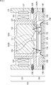
- FIG. 15 is a cross-sectional view showing a configuration example of a second embodiment of a camera module to which the present technology is applied.
- 15 includes a lens unit 120 and an imaging unit 230.
- the camera module 210 is common to the camera module 110 of FIG.
- the camera module 210 is different from the camera module 110 in that an imaging unit 230 is provided instead of the imaging unit 130.
- the imaging unit 230 includes a substrate 131, a support component 132, an IRCF 135, a mounting component 138, and an imaging element 236.
- the imaging unit 230 is common to the imaging unit 130 of FIG. 2 in that the imaging unit 230 includes the substrate 131, the support component 132, the IRCF 135, and the mounting component 138.
- the imaging unit 230 is different from the imaging unit 130 in that an imaging element 236 is provided instead of the imaging element 136.
- the image sensor 236 is a semiconductor device called WLCSP (Wafer Level Chip Size Package), and a protective glass 240 is provided on the light receiving surface side (upper side) that receives light.
- WLCSP Wafer Level Chip Size Package
- An imaging element 236 that is a WLCSP is provided with a solder ball 239 as an electrical contact with the outside.
- the image sensor 236 is mounted on the substrate 131 by flip chip bonding and is electrically connected to the substrate 131 via the solder balls 239.
- a ghost or flare may occur due to reflection of light that has passed through the opening 133 on the side surface of the protective glass 240 provided on the upper side of the image sensor 236 that is a WLCSP.
- the size of the opening 133 can be reduced, the light is reflected from the side surface of the protective glass 240, that is, the light is prevented from entering the side surface of the protective glass 240, ghosts and flare due to light reflection on the side surface of the protective glass 240 can be suppressed.
- FIG. 16 is a cross-sectional view illustrating a configuration example of a third embodiment of a camera module to which the present technology is applied.
- the 16 has a lens unit 120 and an imaging unit 330.
- the camera module 310 is common to the camera module 210 of FIG.
- the camera module 310 is different from the camera module 210 in that an imaging unit 330 is provided instead of the imaging unit 230.
- the imaging unit 330 includes a substrate 131, a support component 132, an IRCF 135, a mounting component 138, an imaging element 236, and a WLL (Wafer Level Lens) 400.
- the imaging unit 330 is common to the imaging unit 230 of FIG. 15 in that it includes the substrate 131, the support component 132, the IRCF 135, the mounting component 138, and the imaging element 236.
- the imaging unit 330 is different from the imaging unit 230 not having the WLL 400 in that the WLL 400 is newly provided.
- WLL 400 is provided on the upper part of imaging element 236 (protective glass 240 provided on the upper side).
- WLCSP with WLL is called WLLCSP (Wafer Level Lens Length Chip Size Package). Therefore, the image sensor 236 provided with the WLL 400 is a WLLCSP.
- a ghost or a flare may occur due to reflection of light that has passed through the opening 133 on the side surface of the protective glass 240 constituting the WLLCSP or the side surface of the WLL 400.
- the size of the opening 133 can be reduced, light is reflected on the side surface of the protective glass 240 or the side surface of the WLL 400, that is, light is incident on the side surface of the protective glass 240 or the WLL 400. It is possible to suppress the ghost and flare caused by the reflection of light on the side surface of the protective glass 240 and the side surface of the WLL 400.
- FIG. 17 is a diagram illustrating a usage example in which the camera modules 110, 210, and 310 to which the present technology is applied are used.
- the camera module 110 can be used in various electronic devices that sense light such as visible light, infrared light, ultraviolet light, and X-ray as follows. The same applies to the camera module 210 of FIG. 15 and the camera module 310 of FIG.
- Electronic devices that capture images for viewing such as digital cameras and mobile devices with camera functions
- Electronic devices used for traffic such as in-vehicle sensors that take pictures of the back, surroundings, inside the car, surveillance cameras that monitor traveling vehicles and roads, and ranging sensors that measure distances between vehicles, etc.
- Electronic devices used in home appliances such as TVs, refrigerators, and air conditioners to capture gestures and perform device operations in accordance with the gestures
- Endoscopes, electron microscopes, and infrared light reception Electronic devices used for medical and healthcare such as angiography devices
- Electronic devices used for security such as surveillance cameras for crime prevention and cameras for personal authentication
- Photographs the skin Photographing skin measuring instrument and scalp Electronic devices used for beauty such as a microscope to perform
- Electronic devices used for sports such as action cameras and wearable cameras for sports applications, etc.
- Embodiments of the present technology are not limited to the above-described embodiments, and various modifications can be made without departing from the gist of the present technology.
- An optical component having an opening through which the light from a lens for condensing light passes, and being disposed so as to cover the opening between the lens and an image sensor that photoelectrically converts the light; Provided with support parts to support the image sensor side, Around the opening is provided a gradient portion that is inclined in the thickness direction of the support component, The support component is disposed so that the inclination of the gradient portion and the lens face each other, The portion of the lens that faces the support component is arranged closer to the first surface than the second surface of the support component opposite to the first surface on which the optical component is arranged.
- Camera module configured to.
- the gradient portion has a step shape as the reflection control structure.
- an inclination angle of the gradient portion with respect to the optical axis of the lens is configured to be larger than an angle with respect to the optical axis of light incident on the tip of the gradient portion from the lens.
Landscapes
- Physics & Mathematics (AREA)
- General Physics & Mathematics (AREA)
- Optics & Photonics (AREA)
- Engineering & Computer Science (AREA)
- Multimedia (AREA)
- Signal Processing (AREA)
- Health & Medical Sciences (AREA)
- Toxicology (AREA)
- Studio Devices (AREA)
- Lens Barrels (AREA)
- Camera Bodies And Camera Details Or Accessories (AREA)
Abstract
本技術は、カメラモジュールを低背化することができるようにするカメラモジュールに関する。 カメラモジュールは、光を集光するレンズからの光が通過する開口部を有し、レンズと光を光電変換する撮像素子との間に、開口部を覆うように配置される光学部品を、撮像素子側に支持する支持部品を備える。また、開口部の周囲には、支持部品の厚さ方向に傾斜する勾配部が設けられ、支持部品は、前記勾配部の傾斜とレンズとが対向するように配置される。さらに、レンズの支持部品と対向する部分が、支持部品の光学部品が配置される第1の面と反対側の第2の面より、前記第1の面側に配置されるように構成される。本技術は、例えば、光を集光し画像を撮像するカメラモジュールに適用できる。
Description
本技術は、カメラモジュールに関し、特に、カメラモジュールを低背化することができるようにするカメラモジュールに関する。
例えば、特許文献1には、カメラモジュールにおけるゴーストの発生を低減又は防止する技術が記載されている。
特許文献1に記載のカメラモジュールでは、IRCF(Infra Red Cut-off Filter)を支持する支持部品に、レンズからの光を通過させるための開口部が設けられており、その開口部を通過した光が、撮像素子に入射する。
カメラモジュールでは、支持部品とレンズとが干渉しないように、支持部品とレンズとの距離を確保する必要がある。このため、レンズと撮像素子との距離を短くすることが困難であり、バックフォーカス(BF:Backfocus)が長いレンズが必要であった。さらに、カメラモジュールの低背化が困難であった。
本技術は、このような状況に鑑みてなされたものであり、カメラモジュールを低背化することができるようにするものである。
本技術のカメラモジュールは、光を集光するレンズからの前記光が通過する開口部を有し、前記レンズと前記光を光電変換する撮像素子との間に、前記開口部を覆うように配置される光学部品を、前記撮像素子側に支持する支持部品を備え、前記開口部の周囲には、前記支持部品の厚さ方向に傾斜する勾配部が設けられ、前記支持部品は、前記勾配部の傾斜と前記レンズとが対向するように配置され、前記レンズの、前記支持部品と対向する部分が、前記支持部品の、前記光学部品が配置される第1の面と反対側の第2の面より、前記第1の面側に配置されるように構成されたカメラモジュールである。
本技術のカメラモジュールにおいては、支持部品は、光を集光するレンズからの前記光が通過する開口部を有し、前記レンズと前記光を光電変換する撮像素子との間に、前記開口部を覆うように配置される光学部品を、前記撮像素子側に支持する。前記開口部の周囲には、前記支持部品の厚さ方向に傾斜する勾配部が設けられており、前記支持部品は、前記勾配部の傾斜と前記レンズとが対向するように配置されている。前記レンズの、前記支持部品と対向する部分は、前記支持部品の、前記光学部品が配置される第1の面と反対側の第2の面より、前記第1の面側に配置されている。
本技術によれば、カメラモジュールを低背化することができる。
なお、ここに記載された効果は必ずしも限定されるものではなく、本開示中に記載されたいずれかの効果であってもよい。
<カメラモジュールの構成例>
図1は、カメラモジュールの構成例を示す断面図である。
図1に示されるカメラモジュール10は、レンズユニット20及び撮像ユニット30を有する。
レンズユニット20は、レンズ21、鏡筒(バレル)22、レンズホルダ23、コイル24、バネ25、アクチュエータユニット26、及び、マグネット27を有する。撮像ユニット30は、基板31、支持部品32、IRCF35、撮像素子36、及び、実装部品38を有する。
レンズユニット20において、レンズ21は、鏡筒22の内部に組み込まれ、鏡筒22は、レンズホルダ23に保持されている。レンズホルダ23は、アクチュエータユニット26内を図中の上下方向に移動することができるように、バネ25によってアクチュエータユニット26内に支持されている。レンズユニット20では、レンズホルダ23が上下方向に移動することで、フォーカスが調整される。本明細書のカメラモジュールの断面図はすべて、レンズ21が最も下方向(撮像素子側)にある状態である「マクロメカ端時」の断面図である。
レンズホルダ23の側面には、コイル24が設けられている。アクチュエータユニット26のコイル24と対向する位置には、マグネット27が設けられている。コイル24に電流が流れると、マグネット27により形成される磁界によって、コイル24が設けられたレンズホルダ23が、上下方向に移動し、すなわち、レンズ21が光軸方向に移動し、フォーカスが調整される。
レンズユニット20(のアクチュエータユニット26)は、基板31上に設けられた撮像素子36の直上に、レンズ21の光軸と、撮像素子36の有効画素37の中心とを合わせた状態で、支持部品32上に接着剤28で接着されている。
支持部品32は、撮像素子36(の有効画素37)の直上部分に、レンズ21からの光が通過する開口部33を有する。開口部33の周囲には、支持部品32の厚さ方向に傾斜する勾配部34が設けられており、支持部品32は、勾配部34の傾斜と撮像素子36とが対向するように配置されている。
支持部品32は、撮像素子36から適切な高さにIRCF35を固定することができる高さに構成され、接着剤40で基板31上に接着されている。
ここで、支持部品32の開口部33の、撮像素子36と対向する側の部分を開口下部33Dといい、支持部品32の開口部33の、レンズ21と対向する側の部分を開口上部33Uという。
IRCF35は、支持部品32の開口部33を覆うように、支持部品32の下側の面(撮像素子36と対向する面)に接着剤等で接着されている。
撮像素子36は、基板31上に設けられ、金線(ワイヤ)39により、基板31と電気的に接続されている。
実装部品38は、例えば、コンデンサ、抵抗、又は、IC(Integrated Circuit)等の電子部品などであり、基板31上の所定の位置に配置され、電気的に接続されている。
以上のように構成されるカメラモジュール10では、レンズ21が光を集光し、その光が、開口部33を通過し、さらに、IRCF35を介して撮像素子36に照射される。撮像素子36では、有効画素37において、撮像素子36に照射される光が光電変換され、これにより、画像が撮像される。
カメラモジュール10では、勾配部34の傾斜が、撮像素子36に対向するように設けられている。そして、カメラモジュール10では、勾配部34の(傾斜の)先端とレンズ21とが干渉しないように、レンズ21は、そのレンズ21の(最)下部(支持部品32と対向する部分)が、開口上部33Uと同じか、やや上部の位置になるように配置されている。
カメラモジュール10では、傾斜が撮像素子36に対向するように設けられた勾配部34の先端と干渉しないように、レンズ21を配置する必要があり、レンズ21を、開口上部33Uより下の位置に下げることが困難である。そのため、カメラモジュール10の低背化が困難である。
また、カメラモジュール10では、勾配部34の先端とレンズ21(の下部)とが干渉することを防止するため、開口部33の開口上部33Uの大きさをある程度の大きさに形成する必要がある。そのため、支持部品32に設けられる開口部33の大きさを小さくすることが困難である。
これにより、カメラモジュール10では、開口部33を通過した、レンズ21からの光が撮像素子36の有効画素37以外の部分、例えば、金線39に入射し、入射した光が金線39で反射して、金線39での光の反射に起因するゴースト及びフレア(金線ゴースト及びフレア)が発生する可能性が高い。
さらに、カメラモジュール10では、勾配部34の傾斜が、撮像素子36に対向するように設けられているので、必然的に、開口部33の開口下部33Dの大きさは開口上部33Uの大きさより大きくなる。したがって、開口部33を覆うように、支持部品32の下側の面に配置されるIRCF35の大きさが大きくなり、IRCF35の大きさが大きくなる分だけ、カメラモジュール10が高コスト化する。
<第1の実施の形態>
図2は、本技術を適用したカメラモジュールの第1の実施の形態の構成例を示す断面図である。
図2に示されるカメラモジュール110は、レンズユニット120及び撮像ユニット130を有する。
レンズユニット120は、レンズ121、鏡筒(バレル)122、レンズホルダ123、コイル124、バネ125、アクチュエータユニット126、及び、マグネット127を有する。撮像ユニット130は、基板131、支持部品132、IRCF135、撮像素子136、及び、実装部品138を有する。
ここで、レンズユニット120のレンズ121、鏡筒122、レンズホルダ123、コイル124、バネ125、アクチュエータユニット126、及び、マグネット127は、図1に示されるレンズユニット20のレンズ21、鏡筒22、レンズホルダ23、コイル24、バネ25、アクチュエータユニット26、及び、マグネット27にそれぞれ対応する。
また、撮像ユニット130の基板131、支持部品132、IRCF135、撮像素子136、及び、実装部品138は、図1に示される撮像ユニット30の基板31、支持部品32、IRCF35、撮像素子36、及び、実装部品38にそれぞれ対応する。
但し、支持部品132は、撮像素子136(の有効画素137)の直上部分に、レンズ121からの光が通過する開口部133を有する。開口部133の周囲には、支持部品132の厚さ方向に傾斜する勾配部134が設けられており、支持部品132は、勾配部134の傾斜とレンズ121とが対向するように配置されている。したがって、支持部品132は、勾配部134の傾斜がレンズ121と対向するように配置されている点で、勾配部34の傾斜が撮像素子36と対向するように配置されている支持部品32と大きく異なる。
支持部品132は、撮像素子136から適切な高さにIRCF135を固定することができる高さに構成され、接着剤140で基板131上に接着されている。
図1のカメラモジュール10では、支持部品32の上側の面(レンズ21と対向する面)側に、勾配部34の先端が位置するのに対して、カメラモジュール110では、支持部品132の下側の面(第1の面)側に、勾配部134の先端が位置する。すなわち、カメラモジュール110では、勾配部134の先端が、カメラモジュール10の勾配部34の先端よりも下側に位置する。そのため、カメラモジュール110では、レンズ121を、カメラモジュール10のレンズ21よりも下側に配置することができる。
ここで、支持部品132の開口部133の、撮像素子136と対向する側の部分を開口下部133Dといい、支持部品132の開口部133の、レンズ121と対向する側の部分を開口上部133Uという。
カメラモジュール110では、傾斜がレンズ121と対向するように勾配部134が形成されているので、開口上部133Uを開口下部33Dよりも小さく、かつ、開口下部133Dを開口上部33Uよりも小さくすることにより、開口部133を開口部33よりも小さく形成しても、開口上部133Uを開口上部33Uより大きくすれば、レンズ121を、レンズ21よりも下側に配置することができる。すなわち、カメラモジュール110では、レンズ121の下部(支持部品132と対向する部分)を、支持部品132の下側の面と反対側の上側の面(第2の面)より、下側の面側に配置することができる。図2では、レンズ121の下部が開口上部133U(第2の面)と開口下部133D(第1の面)との間に位置するように、レンズ121が配置されている。
なお、図2のカメラモジュール110が、IRCF135とは別に、赤外線をカットする機能を有する場合、IRCF135に代えて、例えば、透明カバーフィルム、又は、透明カバーガラス等の透明な板状の光学部品を採用し、その光学部品を支持部品132で支持することができる。
また、図2では、レンズホルダ123が上下方向に移動することで、フォーカスの調整を行うことができるが、レンズホルダ123は、上下方向に移動しないように、撮像ユニット130に固定することができる。この場合、バネ125、アクチュエータユニット126、及び、マグネット127を設けずに、カメラモジュール110を構成することができる。
図3は、図2の撮像ユニット130の構成例を示す平面図である。
図3に示されるように、上から見て略矩形の支持部品132の中央には、略矩形の開口部133が形成されている。開口部133の周囲には、支持部品132の厚さ方向に傾斜する勾配部134が設けられている。勾配部134の傾斜は、支持部品132の上側の面(レンズ121と対向する面)側に形成されている。支持部品132には、開口部133を覆う(塞ぐ)ようにIRCF135が、支持部品132の下側の面(撮像素子136と対向する面)に接着されることにより配置されている。
図4は、カメラモジュール10とカメラモジュール110とを比較する断面図である。
カメラモジュール110では、勾配部134の先端がカメラモジュール10の勾配部34の先端よりも下側(撮像素子136側)に存在する。これにより、例えば、カメラモジュール110のレンズ121の位置が、カメラモジュール10のレンズ21の位置と同一の位置にある場合、勾配部34の先端とレンズ21との距離よりも、勾配部134の先端とレンズ121との距離が遠くなる。したがって、カメラモジュール110では、勾配部134の先端とレンズ121とが干渉する恐れが、カメラモジュール10よりも少ない。
また、カメラモジュール110では、勾配部134の傾斜が支持部品132の上側の面(レンズ121と対向する面)側に形成されていることで、必然的に、開口部133の開口上部133Uの大きさは開口下部133Dの大きさA2より大きくなる。
仮に、カメラモジュール10の開口上部33Uの大きさA1とカメラモジュール110の開口上部133Uの大きさとが同一である場合、開口下部133Dの大きさA2は、開口上部133Uの大きさよりも小さいので、カメラモジュール110の開口下部133Dの大きさA2は、カメラモジュール10の開口上部33Uよりの大きさA1よりも小さくなる。したがって、カメラモジュール110の開口部133の大きさを、カメラモジュール10の開口部33の大きさよりも小さくすることができる。
また、IRCF35及びIRCF135は、支持部品32及び支持部品132の下側の面に、開口部33及び開口部133を覆うようにそれぞれ配置されるので、カメラモジュール10では、開口下部33Dの大きさよりも大きい大きさB1のIRCF35が必要となり、カメラモジュール110では、開口下部133Dの大きさA2よりも大きい大きさB2のIRCF135が必要となる。
カメラモジュール10では、勾配部34の傾斜が支持部品32の下側の面(撮像素子36と対向する面)側に形成されていることで、必然的に、開口部33の開口下部33Dの大きさは開口上部33Uの大きさA1より大きくなる。
仮に、開口下部133Dの大きさA2と開口上部33Uの大きさA1とが同一である場合、開口下部33Dの大きさは、開口上部33Uの大きさA1より大きいので、カメラモジュール110の開口下部133Dの大きさA2よりも大きい。すなわち、開口下部133Dの大きさA2は、開口下部33Dの大きさよりも小さい。したがって、開口下部133Dを覆うように配置されるIRCF135の大きさB2は、開口下部33Dを覆うように配置されるIRCF35の大きさB1よりも小さくすることができる。
また、カメラモジュール110では、レンズ121がレンズ21と同一の位置(高さ)に配置される場合、勾配部134の先端とレンズ121とが干渉する恐れが、カメラモジュール10よりも少ないので、レンズ121を、レンズ21よりも、撮像素子136側に下げた位置に配置することができる。この場合、カメラモジュール110のレンズユニット120の高さC2を、カメラモジュール10のレンズユニット20の高さC1よりも低くすることができ、その結果、レンズユニット120の全体の高さ(全高)を低くし、カメラモジュール110を低背化することができる。
ここで、レンズユニット120において、レンズ121の下側の部分、すなわち、レンズ121の支持部品132と対向する部分が、鏡筒122の下部から出ている場合、カメラモジュール110の低背化を、より効果的に実現することができる。
以上、カメラモジュール110の全体の構成について説明したが、以下では、カメラモジュール110の支持部品132の勾配部134の構成の詳細について説明する。
<勾配部134の構成例>
勾配部134は、レンズ121からの光の反射を制限する反射制御構造を有するように構成することができる。
図5は、勾配部134の第1の構成例を示す断面図である。
図5では、カメラモジュール110の勾配部134(の傾斜)は、反射制御構造としての階段状の構造に構成されている。
以上のように、勾配部134が階段状に構成されていることで、勾配部134が、連続的に(滑らかに)傾斜している場合よりも、レンズ121から勾配部134に入射する光の入射角が大きくなり、レンズ121から勾配部134に入射する光は、レンズ121の外側に向かって反射しやすくなる。したがって、勾配部134で反射した光が、レンズ121に戻る(向かって反射する)ことを抑制することができ、その結果、勾配部134で反射した光により発生するゴースト及びフレアを抑制することができる。
図6は、勾配部134の第1の構成例の傾斜を説明する断面図である。
勾配部134は、レンズ121の光軸に対する勾配部134の傾斜の角度が、レンズ121から勾配部134の先端に入射する光の、レンズ121の光軸に対する角度(光の入射角)より大きくなるように構成することができる。
図6では、レンズ121から勾配部134の先端に入射する光の入射角が、38度になっており、レンズ121の光軸に対する勾配部134の傾斜の角度(以下、傾斜角ともいう)は、38度よりも大きい60度になっている。
以上のように、階段状に構成される勾配部134の傾斜角が、レンズ121から勾配部134の先端に入射する光の入射角より大きい場合、勾配部134の階段の蹴込み(立壁)部分(垂直部分)が低くなる。したがって、勾配部134の階段の踏板部分(水平部分)で反射した光が階段の蹴込み部分でさらに反射することを抑制することができる。これにより、レンズ121から勾配部134に入射した光が階段の蹴込み部分で反射することで発生する2次反射光によるゴースト及びフレアの発生を抑制することができる。
図7は、勾配部134の第2の構成例を示す断面図である。
図7では、カメラモジュール110の勾配部134は、反射制御構造として、光の反射を防止する反射防止膜が勾配部134の傾斜に形成された構造を有している。
反射防止膜は、例えば、反射防止剤の塗布、又は、反射防止シートの貼付等によって形成することができる。
以上のように、勾配部134に反射防止膜が形成されている場合、レンズ121から勾配部134に入射する光の反射を防止することができる。したがって、勾配部134で反射した光により発生するゴースト及びフレアを抑制することができる。
なお、図7では、勾配部134が連続的に傾斜しているが、勾配部134は、図5に示したように、階段状に構成し、その階段状の勾配部134に、反射防止膜を形成することができる。
図8は、勾配部134の傾斜と、レンズ121との関係の例を説明する断面図である。
勾配部134の傾斜は、断面視で、レンズ121の下側の部分(支持部品132と対向する部分)の面の接線と略並行する、直線状の形状に構成することができる。
以上のように、勾配部134の傾斜を、レンズ121の下側の部分の面の接線と略並行する形状に構成する場合、レンズ121をさらに下側(撮像素子136側)に配置することができる。これにより、レンズユニット120の全高をさらに低くすることができ、その結果、カメラモジュール110をさらに低背化することができる。
なお、図8では、勾配部134が階段状に構成されているが、勾配部134は、例えば、図7に示したように、連続的に傾斜するように構成することができる。
図9は、勾配部134の傾斜と、レンズ121との関係の他の例を説明する断面図である。
勾配部134の傾斜は、断面視で、レンズ121の下側の部分(支持部品132と対向する部分)の面と略並行する、曲線状の形状(非線形の形状)に構成することができる。
以上のように、勾配部134の傾斜を、レンズ121の下側の部分の面と略並行する形状に構成する場合、レンズ121をさらに下側に配置することができる。これにより、レンズユニット120の全高をさらに低くすることができ、その結果、カメラモジュール110をさらに低背化することができる。
なお、図9では、勾配部134は、階段状に構成されているが、勾配部134は、例えば、図7に示したように、連続的に傾斜するように構成することができる。
図10は、勾配部134が連続的に傾斜する場合の、勾配部134の傾斜と、レンズ121との関係の例を説明する断面図である。
図10では、勾配部134は、連続的に傾斜するように構成され、勾配部134の傾斜は、断面視で、レンズ121の下側の部分(支持部品132と対向する部分)の面と略並行する、曲線状の形状に構成されている。また、図10では、勾配部134に、反射防止膜が形成されている。
以上のように、勾配部134の傾斜を、レンズ121の下側の部分の面と略並行する形状に構成する場合、レンズ121をさらに下側に配置することができる。これにより、レンズユニット120の全高をさらに低くすることができ、その結果、カメラモジュール110をさらに低背化することができる。
図11は、勾配部134の第3の構成例を示す断面図である。
図11において、勾配部134は、図5と同様に階段状に構成されている。
さらに、図11では、勾配部134には、支持部品132の下側の面側に、勾配部134の先端から凹んだ溝である樹脂溜まり部150が設けられている。
IRCF135は、支持部品132の下側の面に所定の接着幅Wで接着される。IRCF135を接着するための接着剤としては、例えば、UV(Ultra Violet)接着剤等の樹脂を採用することができる。
以上のように、勾配部134に樹脂溜まり部150が設けられている場合、IRCF135が支持部品132の下側の面にUV接着剤で接着されたときに、IRCF135の、樹脂溜まり部150側にはみ出したUV接着剤を、樹脂溜まり部150に溜めることができる。したがって、UV接着剤が、支持部品132の勾配部134の先端よりはみ出すことを防止することができる。
これにより、UV接着剤が、支持部品132の勾配部134の先端よりはみ出した場合に、そのはみ出したUV接着剤でレンズ121からの光が反射すること、並びに、そのUV接着剤で反射した光により発生するゴースト及びフレアを抑制することができる。
図12は、勾配部134の第4の構成例を示す断面図である。
なお、図中、図11と対応する部分については同一の符号を付してあり、以下では、その説明については適宜省略する。
図12の勾配部134は、傾斜が連続的に構成され、反射防止膜が形成されている点を除き、傾斜が階段状に構成される図11の場合と同様に構成される。
したがって、図12でも、図11の場合と同様に、UV接着剤で光が反射することにより発生するゴースト及びフレアを抑制することができる。
IRCF135を、支持部品132に接着する接着剤としては、UV接着剤の他、熱可塑性樹脂又は熱硬化性樹脂を採用することができる。接着剤としての熱可塑性樹脂又は熱硬化性樹脂としては、黒色の熱可塑性樹脂又は熱硬化性樹脂を採用することができる。
IRCF135を、支持部品132に接着する接着剤として、黒色の熱可塑性樹脂又は熱硬化性樹脂を採用する場合には、支持部品132とIRCF135との接着部分からはみ出した熱可塑性樹脂又は熱硬化性樹脂での、レンズ121からの光の反射が防止されるため、図11及び図12のように、勾配部134の先端に、樹脂溜まり部150を設ける必要は、必ずしもない。
すなわち、IRCF135を支持部品132に接着する接着剤として、黒色の熱可塑性樹脂又は熱硬化性樹脂を採用する場合、勾配部134は、樹脂溜まり部150を設けずに構成することができる。
図13及び図14は、接着剤として、黒色の熱可塑性樹脂又は熱硬化性樹脂が採用される場合の、支持部品132とIRCF135との接着例を示す断面図である。
接着剤として、黒色の熱可塑性樹脂又は熱硬化性樹脂が採用される場合には、勾配部134の先端に樹脂溜まり部150を設けずに支持部品132を構成し、その支持部品132とIRCF135とを接着することができる。
なお、図13では、勾配部134は、階段状に構成されており、図14では、勾配部134の傾斜が連続的に構成され、その傾斜には、反射防止膜が形成されている。
IRCF135が、支持部品132の下側の面に黒色の熱可塑性樹脂又は熱硬化性樹脂で接着される場合、その黒色の熱可塑性樹脂又は熱硬化性樹脂が、支持部品132の勾配部134の先端よりはみ出しても、はみ出した黒色の熱可塑性樹脂又は熱硬化性樹脂にレンズ121からの光が入射したときに、その光の反射を防止することができる。したがって、図11及び図12で示した樹脂溜まり部150を設けることなく、はみ出した黒色の熱可塑性樹脂又は熱硬化性樹脂にレンズ121からの光が反射することで発生するゴースト及びフレアを抑制することができる。
また、樹脂溜まり部150を設けない場合、樹脂溜まり部150を設ける場合に比較して、IRCF135の接着幅Wを長く確保することができる。したがって、樹脂溜まり部150を設けない場合において、樹脂溜まり部150を設ける場合と同一の接着幅Wを確保するときには、IRCF135の大きさを小さくすることができる。
なお、接着剤として、黒色の熱可塑性樹脂又は熱硬化性樹脂が採用される場合であっても、樹脂たまり部150を設けることができる。
以上のように、カメラモジュール110において、支持部品132を、勾配部134の傾斜とレンズ121とが対向するように配置することで、レンズ121を、カメラモジュール10のレンズ21と同一の位置(高さ)に配置した場合には、勾配部134の先端がカメラモジュール10の勾配部34の先端よりも下側(撮像素子136側)に存在するので、勾配部134の先端とレンズ121の下側の部分との距離が遠くなり、勾配部134の先端とレンズ121の下側の部分とが干渉しにくくなる。したがって、カメラモジュール110によれば、カメラモジュール10よりも、レンズ121を配置する位置の物理的制約が緩くなる。
これにより、カメラモジュール110では、レンズ121を下側(撮像素子136側)に配置することができ、レンズ121と撮像素子136との距離を短くすることができる。したがって、レンズ121として、BFが短いレンズを採用することができる。また、レンズ121の設計の自由度を向上することができ、レンズ121として、特性(性能)の良いレンズを設計して、採用することができる。
さらに、レンズ121の全高を低くすることや、カメラモジュール110を低背化することができる。
なお、カメラモジュール110の低背化に代えて、その低背化の分をレンズの設計の自由度に充てて、レンズ121の性能を向上させることができる。
また、カメラモジュール110では、開口部133の大きさを小さくすること、すなわち、カメラモジュール110では、開口下部133Dの大きさを、カメラモジュール10の開口下部33Dの大きさよりも小さくすることができる。したがって、開口部133(の開口下部133D)を覆うように配置されるIRCF135の大きさを、開口部33(の開口下部33D)を覆うように配置されるIRCF35の大きさよりも小さくすることができ、その結果、IRCF135のコストを削減することができる。
さらに、カメラモジュール110では、開口部133の大きさを小さくすることができるので、開口部133を通過したレンズ121からの光が、金線139や図示せぬ電極パッド等の、撮像素子136の有効画素137の外側に入射することを抑制することができる。その結果、レンズ121からの光が撮像素子136の有効画素137の外側で反射することにより生じる迷光を抑制し、かかる迷光によるゴースト及びフレアを低減することができる。
<第2の実施の形態>
図15は、本技術を適用したカメラモジュールの第2の実施の形態の構成例を示す断面図である。
なお、図中、図2と対応する部分については同一の符号を付してあり、以下では、その説明については適宜省略する。
図15に示されるカメラモジュール210は、レンズユニット120及び撮像ユニット230を有する。
したがって、カメラモジュール210は、レンズユニット120を有する点で、図2のカメラモジュール110と共通する。
但し、カメラモジュール210は、撮像ユニット130に代えて、撮像ユニット230が設けられている点で、カメラモジュール110と相違する。
撮像ユニット230は、基板131、支持部品132、IRCF135、実装部品138、及び、撮像素子236を有する。
したがって、撮像ユニット230は、基板131、支持部品132、IRCF135、及び、実装部品138を有する点で、図2の撮像ユニット130と共通する。
但し、撮像ユニット230は、撮像素子136に代えて、撮像素子236が設けられている点で、撮像ユニット130と相違する。
撮像素子236は、WLCSP(Wafer Level Chip Size Package)と呼ばれる半導体装置であり、光を受光する受光面側(上側)に保護ガラス240が設けられている。
WLCSPである撮像素子236には、外部との電気的な接点として、はんだボール239が設けられている。撮像素子236は、フリップチップボンディングにより基板131に実装され、はんだボール239を介して、基板131と電気的に接続される。
カメラモジュール210では、WLCSPである撮像素子236の上側に設けられている保護ガラス240の側面で、開口部133を通過した光が反射することによるゴーストやフレアが生じ得る。但し、カメラモジュール210では、開口部133の大きさを小さくすることができるので、保護ガラス240の側面で光が反射すること、すなわち、保護ガラス240の側面に光が入射することを抑制し、保護ガラス240の側面での光の反射に起因するゴースト及びフレアを抑制することができる。
<第3の実施の形態>
図16は、本技術を適用したカメラモジュールの第3の実施の形態の構成例を示す断面図である。
なお、図中、図15と対応する部分については同一の符号を付してあり、以下では、その説明については適宜省略する。
図16に示されるカメラモジュール310は、レンズユニット120及び撮像ユニット330を有する。
したがって、カメラモジュール310は、レンズユニット120を有する点で、図15のカメラモジュール210と共通する。
但し、カメラモジュール310は、撮像ユニット230に代えて、撮像ユニット330が設けられている点で、カメラモジュール210と相違する。
撮像ユニット330は、基板131、支持部品132、IRCF135、実装部品138、撮像素子236、及び、WLL(Wafer Level Lens)400を有する。
したがって、撮像ユニット330は、基板131、支持部品132、IRCF135、実装部品138、及び、撮像素子236を有する点で、図15の撮像ユニット230と共通する。
但し、撮像ユニット330は、WLL400が新たに設けられている点で、WLL400を有していない撮像ユニット230と相違する。
WLL400は、撮像素子236(の上側に設けられている保護ガラス240)の上部に設けられている。
WLLが設けられたWLCSPは、WLLCSP(Wafer Level Lens Chip Size Package)と呼ばれる。したがって、WLL400が設けられた撮像素子236は、WLLCSPである。
カメラモジュール310では、WLLCSPを構成する保護ガラス240の側面やWLL400の側面で、開口部133を通過した光が反射することによるゴーストやフレアが生じ得る。但し、カメラモジュール310では、開口部133の大きさを小さくすることができるので、保護ガラス240の側面やWLL400の側面で光が反射すること、すなわち、保護ガラス240やWLL400の側面に光が入射することを抑制し、保護ガラス240の側面やWLL400の側面での光の反射に起因するゴースト及びフレアを抑制することができる。
<カメラモジュールの使用例>
図17は、本技術を適用したカメラモジュール110、210、及び、310を使用する使用例を示す図である。
カメラモジュール110は、例えば、以下のように、可視光や、赤外光、紫外光、X線等の光をセンシングする様々な電子機器に使用することができる。図15のカメラモジュール210及び図16のカメラモジュール310についても同様である。
・ディジタルカメラや、カメラ機能付きの携帯機器等の、鑑賞の用に供される画像を撮影する電子機器
・自動停止等の安全運転や、運転者の状態の認識等のために、自動車の前方や後方、周囲、車内等を撮影する車載用センサ、走行車両や道路を監視する監視カメラ、車両間等の測距を行う測距センサ等の、交通の用に供される電子機器
・ユーザのジェスチャを撮影して、そのジェスチャに従った機器操作を行うために、TVや、冷蔵庫、エアーコンディショナ等の家電に供される電子機器
・内視鏡や、電子顕微鏡、赤外光の受光による血管撮影を行う装置等の、医療やヘルスケアの用に供される電子機器
・防犯用途の監視カメラや、人物認証用途のカメラ等の、セキュリティの用に供される電子機器
・肌を撮影する肌測定器や、頭皮を撮影するマイクロスコープ等の、美容の用に供される電子機器
・スポーツ用途等向けのアクションカメラやウェアラブルカメラ等の、スポーツの用に供される電子機器
・畑や作物の状態を監視するためのカメラ等の、農業の用に供される電子機器
本技術の実施の形態は、上述した実施の形態に限定されるものではなく、本技術の要旨を逸脱しない範囲において種々の変更が可能である。
なお、本明細書に記載された効果はあくまで例示であって限定されるものではなく、本明細書に記載されたもの以外に効果があってもよい。
<その他>
本技術は、以下のような構成をとることができる。
(1)
光を集光するレンズからの前記光が通過する開口部を有し、前記レンズと前記光を光電変換する撮像素子との間に、前記開口部を覆うように配置される光学部品を、前記撮像素子側に支持する支持部品を備え、
前記開口部の周囲には、前記支持部品の厚さ方向に傾斜する勾配部が設けられ、
前記支持部品は、前記勾配部の傾斜と前記レンズとが対向するように配置され、
前記レンズの、前記支持部品と対向する部分が、前記支持部品の、前記光学部品が配置される第1の面と反対側の第2の面より、前記第1の面側に配置される
ように構成されたカメラモジュール。
(2)
前記勾配部は、前記レンズからの光の反射を制御する反射制御構造を有する
(1)に記載のカメラモジュール。
(3)
前記反射制御構造として、前記勾配部が、階段状になっている
(2)に記載のカメラモジュール。
(4)
前記レンズの光軸に対する前記勾配部の傾斜の角度が、前記レンズから前記勾配部の先端に入射する光の、前記光軸に対する角度より大きい
ように構成された(3)に記載のカメラモジュール。
(5)
前記反射制御構造として、前記勾配部に、光の反射を防止する反射防止膜が形成された
(2)に記載のカメラモジュール。
(6)
前記勾配部が、前記レンズの、前記支持部品と対向する部分の面の接線と並行する形状になっている
(1)ないし(5)のいずれかに記載のカメラモジュール。
(7)
前記勾配部が、前記レンズの、前記支持部品と対向する部分の面と並行する形状になっている
(1)ないし(5)のいずれかに記載のカメラモジュール。
(8)
前記支持部品の前記第1の面に、前記勾配部の先端から凹んだ溝が設けられた
(1)ないし(7)のいずれかに記載のカメラモジュール。
(9)
前記光学部品が、前記支持部品の前記第1の面に、接着剤で接着された
(8)に記載のカメラモジュール。
(10)
前記光学部品が、前記支持部品の前記第1の面に、熱可塑性樹脂又は熱硬化性樹脂で接着された
(1)ないし(9)のいずれかに記載のカメラモジュール。
(11)
前記光学部品は、IRCF(Infrared Cut-off Filter)である
(1)ないし(10)のいずれかに記載のカメラモジュール。
10 カメラモジュール, 20 レンズユニット, 21 レンズ, 22 鏡筒, 23 レンズホルダ, 24 コイル, 25 バネ, 26 アクチュエータユニット, 27 マグネット, 28 接着剤, 30 撮像ユニット, 31 基板, 32 支持部品, 33 開口部, 33U 開口上部, 33D 開口下部, 34 勾配部, 35 IRCF, 36 撮像素子, 37 有効画素, 38 実装部品, 39 金線, 40 接着剤, 110 カメラモジュール, 120 レンズユニット, 121 レンズ, 122 鏡筒, 123 レンズホルダ, 124 コイル, 125 バネ, 126 アクチュエータユニット, 127 マグネット, 128 接着剤, 130 撮像ユニット, 131 基板, 132 支持部品, 133 開口部, 133U 開口上部, 133D 開口下部, 134 勾配部, 135 IRCF, 136 撮像素子, 137 有効画素, 138 実装部品, 139 金線, 140 接着剤, 150 樹脂溜まり部, 210 カメラモジュール, 230 撮像ユニット, 236 撮像素子, 239 はんだボール, 240 保護ガラス, 310 カメラモジュール, 400 WLL
Claims (11)
- 光を集光するレンズからの前記光が通過する開口部を有し、前記レンズと前記光を光電変換する撮像素子との間に、前記開口部を覆うように配置される光学部品を、前記撮像素子側に支持する支持部品を備え、
前記開口部の周囲には、前記支持部品の厚さ方向に傾斜する勾配部が設けられ、
前記支持部品は、前記勾配部の傾斜と前記レンズとが対向するように配置され、
前記レンズの、前記支持部品と対向する部分が、前記支持部品の、前記光学部品が配置される第1の面と反対側の第2の面より、前記第1の面側に配置される
ように構成されたカメラモジュール。 - 前記勾配部は、前記レンズからの光の反射を制御する反射制御構造を有する
請求項1に記載のカメラモジュール。 - 前記反射制御構造として、前記勾配部が、階段状になっている
請求項2に記載のカメラモジュール。 - 前記レンズの光軸に対する前記勾配部の傾斜の角度が、前記レンズから前記勾配部の先端に入射する光の、前記光軸に対する角度より大きい
ように構成された請求項3に記載のカメラモジュール。 - 前記反射制御構造として、前記勾配部に、光の反射を防止する反射防止膜が形成された
請求項2に記載のカメラモジュール。 - 前記勾配部が、前記レンズの、前記支持部品と対向する部分の面の接線と並行する形状になっている
請求項1に記載のカメラモジュール。 - 前記勾配部が、前記レンズの、前記支持部品と対向する部分の面と並行する形状になっている
請求項1に記載のカメラモジュール。 - 前記支持部品の前記第1の面に、前記勾配部の先端から凹んだ溝が設けられた
請求項1に記載のカメラモジュール。 - 前記光学部品が、前記支持部品の前記第1の面に、接着剤で接着された
請求項8に記載のカメラモジュール。 - 前記光学部品が、前記支持部品の前記第1の面に、熱可塑性樹脂又は熱硬化性樹脂で接着された
請求項1に記載のカメラモジュール。 - 前記光学部品は、IRCF(Infrared Cut-off Filter)である
請求項1に記載のカメラモジュール。
Priority Applications (3)
| Application Number | Priority Date | Filing Date | Title |
|---|---|---|---|
| US16/970,773 US11960139B2 (en) | 2018-02-27 | 2019-02-13 | Camera module |
| CN201980010291.3A CN111656239A (zh) | 2018-02-27 | 2019-02-13 | 相机模块 |
| EP19760433.3A EP3761097B1 (en) | 2018-02-27 | 2019-02-13 | Camera module |
Applications Claiming Priority (2)
| Application Number | Priority Date | Filing Date | Title |
|---|---|---|---|
| JP2018033206A JP2019148698A (ja) | 2018-02-27 | 2018-02-27 | カメラモジュール |
| JP2018-033206 | 2018-02-27 |
Publications (1)
| Publication Number | Publication Date |
|---|---|
| WO2019167607A1 true WO2019167607A1 (ja) | 2019-09-06 |
Family
ID=67806111
Family Applications (1)
| Application Number | Title | Priority Date | Filing Date |
|---|---|---|---|
| PCT/JP2019/004932 Ceased WO2019167607A1 (ja) | 2018-02-27 | 2019-02-13 | カメラモジュール |
Country Status (5)
| Country | Link |
|---|---|
| US (1) | US11960139B2 (ja) |
| EP (1) | EP3761097B1 (ja) |
| JP (1) | JP2019148698A (ja) |
| CN (1) | CN111656239A (ja) |
| WO (1) | WO2019167607A1 (ja) |
Families Citing this family (4)
| Publication number | Priority date | Publication date | Assignee | Title |
|---|---|---|---|---|
| JP7277268B2 (ja) * | 2019-06-06 | 2023-05-18 | キヤノン株式会社 | 光学素子、光学機器、撮像装置および光学素子の製造方法 |
| CN113114899B (zh) | 2021-04-15 | 2022-02-25 | 维沃移动通信有限公司 | 摄像装置及电子设备 |
| EP4277244B1 (en) * | 2021-06-04 | 2025-11-12 | Samsung Electronics Co., Ltd. | Electronic device comprising window for optical module |
| US20230411540A1 (en) * | 2022-06-16 | 2023-12-21 | Taiwan Semiconductor Manufacturing Company Limited | Semiconductor device and method of making |
Citations (5)
| Publication number | Priority date | Publication date | Assignee | Title |
|---|---|---|---|---|
| JP2006208865A (ja) | 2005-01-28 | 2006-08-10 | Mitsumi Electric Co Ltd | カメラモジュール |
| JP2007233262A (ja) * | 2006-03-03 | 2007-09-13 | Konica Minolta Opto Inc | 撮像装置及び携帯端末 |
| JP2008233512A (ja) * | 2007-03-20 | 2008-10-02 | Hitachi Maxell Ltd | レンズユニット |
| JP2014096622A (ja) * | 2012-11-07 | 2014-05-22 | Konica Minolta Inc | カメラモジュール及び携帯端末 |
| JP2016080865A (ja) * | 2014-10-16 | 2016-05-16 | 富士フイルム株式会社 | カメラモジュール及び電子機器 |
Family Cites Families (5)
| Publication number | Priority date | Publication date | Assignee | Title |
|---|---|---|---|---|
| JP4365743B2 (ja) | 2004-07-27 | 2009-11-18 | 富士通マイクロエレクトロニクス株式会社 | 撮像装置 |
| US20100225854A1 (en) * | 2006-02-20 | 2010-09-09 | Nitto Denko Corporation | Liquid crystal panel and liquid crystal display apparatus using the panel |
| JP4764942B2 (ja) | 2008-09-25 | 2011-09-07 | シャープ株式会社 | 光学素子、光学素子ウエハ、光学素子ウエハモジュール、光学素子モジュール、光学素子モジュールの製造方法、電子素子ウエハモジュール、電子素子モジュールの製造方法、電子素子モジュールおよび電子情報機器 |
| JP2012247365A (ja) * | 2011-05-30 | 2012-12-13 | Three M Innovative Properties Co | 感圧式指紋センサー用フィルム積層体及びこのフィルム積層体を用いた感圧式指紋センサー |
| JP2015099262A (ja) | 2013-11-19 | 2015-05-28 | ソニー株式会社 | 固体撮像装置およびカメラモジュール、並びに電子機器 |
-
2018
- 2018-02-27 JP JP2018033206A patent/JP2019148698A/ja active Pending
-
2019
- 2019-02-13 EP EP19760433.3A patent/EP3761097B1/en active Active
- 2019-02-13 US US16/970,773 patent/US11960139B2/en active Active
- 2019-02-13 CN CN201980010291.3A patent/CN111656239A/zh active Pending
- 2019-02-13 WO PCT/JP2019/004932 patent/WO2019167607A1/ja not_active Ceased
Patent Citations (5)
| Publication number | Priority date | Publication date | Assignee | Title |
|---|---|---|---|---|
| JP2006208865A (ja) | 2005-01-28 | 2006-08-10 | Mitsumi Electric Co Ltd | カメラモジュール |
| JP2007233262A (ja) * | 2006-03-03 | 2007-09-13 | Konica Minolta Opto Inc | 撮像装置及び携帯端末 |
| JP2008233512A (ja) * | 2007-03-20 | 2008-10-02 | Hitachi Maxell Ltd | レンズユニット |
| JP2014096622A (ja) * | 2012-11-07 | 2014-05-22 | Konica Minolta Inc | カメラモジュール及び携帯端末 |
| JP2016080865A (ja) * | 2014-10-16 | 2016-05-16 | 富士フイルム株式会社 | カメラモジュール及び電子機器 |
Non-Patent Citations (1)
| Title |
|---|
| See also references of EP3761097A4 |
Also Published As
| Publication number | Publication date |
|---|---|
| EP3761097B1 (en) | 2025-09-03 |
| US11960139B2 (en) | 2024-04-16 |
| EP3761097A4 (en) | 2021-04-07 |
| EP3761097A1 (en) | 2021-01-06 |
| CN111656239A (zh) | 2020-09-11 |
| US20210096318A1 (en) | 2021-04-01 |
| JP2019148698A (ja) | 2019-09-05 |
Similar Documents
| Publication | Publication Date | Title |
|---|---|---|
| JP7447165B2 (ja) | カメラモジュール | |
| US10763286B2 (en) | Semiconductor device, manufacturing method thereof, and electronic apparatus | |
| WO2019167607A1 (ja) | カメラモジュール | |
| CN108701696B (zh) | 玻璃中介层模块、成像装置和电子设备 | |
| WO2017135062A1 (ja) | 半導体装置および製造方法、撮像装置、並びに電子機器 | |
| CN108140648A (zh) | 固态成像器件封装和制造方法,及电子装置 | |
| US20180175089A1 (en) | Camera module and electronic apparatus | |
| TW201316756A (zh) | 攝像模組 | |
| KR102354606B1 (ko) | 카메라 모듈 및 광학 기기 | |
| US9077880B2 (en) | Image capturing module and image sensing unit thereof | |
| US11315966B2 (en) | Solid-state imaging element, manufacturing method, and electronic apparatus | |
| JPWO2018056069A1 (ja) | カメラモジュール、製造方法、及び、電子機器 | |
| US9432558B2 (en) | Image capturing module having a built-in dustproof structure | |
| US20150116575A1 (en) | Image capturing module and optical auxiliary unit thereof | |
| KR102072775B1 (ko) | 카메라 모듈 | |
| KR20200012011A (ko) | 렌즈 구동장치 및 이를 포함하는 정보기술 기기 | |
| JP2013005116A (ja) | カメラモジュールおよびそれを備えた電子機器 | |
| CN105025205A (zh) | 具有内建式防尘结构的影像撷取模块 | |
| KR20230088102A (ko) | 카메라 모듈 및 광학기기 | |
| CN105898114B (zh) | 图像获取模块 | |
| KR20210143544A (ko) | 이미지 센서 패키지 및 이를 포함하는 카메라 장치 | |
| KR20100083372A (ko) | 카메라 모듈 | |
| WO2016194577A1 (ja) | 撮像素子、撮像方法、プログラム、並びに電子機器 |
Legal Events
| Date | Code | Title | Description |
|---|---|---|---|
| 121 | Ep: the epo has been informed by wipo that ep was designated in this application |
Ref document number: 19760433 Country of ref document: EP Kind code of ref document: A1 |
|
| NENP | Non-entry into the national phase |
Ref country code: DE |
|
| ENP | Entry into the national phase |
Ref document number: 2019760433 Country of ref document: EP Effective date: 20200928 |
|
| WWG | Wipo information: grant in national office |
Ref document number: 2019760433 Country of ref document: EP |