WO2019167671A1 - マイクロホンアレイ、収録装置および方法、並びにプログラム - Google Patents
マイクロホンアレイ、収録装置および方法、並びにプログラム Download PDFInfo
- Publication number
- WO2019167671A1 WO2019167671A1 PCT/JP2019/005555 JP2019005555W WO2019167671A1 WO 2019167671 A1 WO2019167671 A1 WO 2019167671A1 JP 2019005555 W JP2019005555 W JP 2019005555W WO 2019167671 A1 WO2019167671 A1 WO 2019167671A1
- Authority
- WO
- WIPO (PCT)
- Prior art keywords
- microphone array
- microphone
- array
- spherical harmonic
- recording
- Prior art date
- Legal status (The legal status is an assumption and is not a legal conclusion. Google has not performed a legal analysis and makes no representation as to the accuracy of the status listed.)
- Ceased
Links
Images





Classifications
-
- H—ELECTRICITY
- H04—ELECTRIC COMMUNICATION TECHNIQUE
- H04R—LOUDSPEAKERS, MICROPHONES, GRAMOPHONE PICK-UPS OR LIKE ACOUSTIC ELECTROMECHANICAL TRANSDUCERS; ELECTRIC HEARING AIDS; PUBLIC ADDRESS SYSTEMS
- H04R1/00—Details of transducers, loudspeakers or microphones
- H04R1/20—Arrangements for obtaining desired frequency or directional characteristics
- H04R1/32—Arrangements for obtaining desired frequency or directional characteristics for obtaining desired directional characteristic only
- H04R1/40—Arrangements for obtaining desired frequency or directional characteristics for obtaining desired directional characteristic only by combining a number of identical transducers
-
- H—ELECTRICITY
- H04—ELECTRIC COMMUNICATION TECHNIQUE
- H04R—LOUDSPEAKERS, MICROPHONES, GRAMOPHONE PICK-UPS OR LIKE ACOUSTIC ELECTROMECHANICAL TRANSDUCERS; ELECTRIC HEARING AIDS; PUBLIC ADDRESS SYSTEMS
- H04R1/00—Details of transducers, loudspeakers or microphones
- H04R1/20—Arrangements for obtaining desired frequency or directional characteristics
- H04R1/22—Arrangements for obtaining desired frequency or directional characteristics for obtaining desired frequency characteristic only
- H04R1/222—Arrangements for obtaining desired frequency or directional characteristics for obtaining desired frequency characteristic only for microphones
-
- H—ELECTRICITY
- H04—ELECTRIC COMMUNICATION TECHNIQUE
- H04R—LOUDSPEAKERS, MICROPHONES, GRAMOPHONE PICK-UPS OR LIKE ACOUSTIC ELECTROMECHANICAL TRANSDUCERS; ELECTRIC HEARING AIDS; PUBLIC ADDRESS SYSTEMS
- H04R3/00—Circuits for transducers
- H04R3/005—Circuits for transducers for combining the signals of two or more microphones
-
- H—ELECTRICITY
- H04—ELECTRIC COMMUNICATION TECHNIQUE
- H04R—LOUDSPEAKERS, MICROPHONES, GRAMOPHONE PICK-UPS OR LIKE ACOUSTIC ELECTROMECHANICAL TRANSDUCERS; ELECTRIC HEARING AIDS; PUBLIC ADDRESS SYSTEMS
- H04R1/00—Details of transducers, loudspeakers or microphones
- H04R1/20—Arrangements for obtaining desired frequency or directional characteristics
- H04R1/32—Arrangements for obtaining desired frequency or directional characteristics for obtaining desired directional characteristic only
- H04R1/40—Arrangements for obtaining desired frequency or directional characteristics for obtaining desired directional characteristic only by combining a number of identical transducers
- H04R1/406—Arrangements for obtaining desired frequency or directional characteristics for obtaining desired directional characteristic only by combining a number of identical transducers microphones
-
- H—ELECTRICITY
- H04—ELECTRIC COMMUNICATION TECHNIQUE
- H04R—LOUDSPEAKERS, MICROPHONES, GRAMOPHONE PICK-UPS OR LIKE ACOUSTIC ELECTROMECHANICAL TRANSDUCERS; ELECTRIC HEARING AIDS; PUBLIC ADDRESS SYSTEMS
- H04R2201/00—Details of transducers, loudspeakers or microphones covered by H04R1/00 but not provided for in any of its subgroups
- H04R2201/40—Details of arrangements for obtaining desired directional characteristic by combining a number of identical transducers covered by H04R1/40 but not provided for in any of its subgroups
- H04R2201/401—2D or 3D arrays of transducers
Definitions
- the present technology relates to a microphone array, a recording apparatus and method, and a program, and more particularly, to a microphone array, a recording apparatus and method, and a program that enable low-cost and wide-band sound field recording.
- Wavefront synthesis / restoration technology enables sound image localization and spatial noise cancellation of objects placed in space, providing a more realistic acoustic experience compared to conventional multi-channel playback methods. it can.
- open-type annular microphone arrays composed of omnidirectional microphones are used in various applications.
- such a microphone arrangement design of the annular microphone array is not suitable for recording a wavefront (sound field) of a wide frequency band. This is because, when an annular microphone array is used, a mode function known as a Bessel function for obtaining a spherical harmonic coefficient of a wavefront of recorded sound becomes zero in a predetermined frequency band.
- a plurality of microphones are arranged in a double or more multiple ring, a cardioid directional microphone is used (for example, see Non-Patent Document 1), a rigid baffle is used, and a mode function is used. It is conceivable to reduce the region in which the zero becomes zero.
- Non-Patent Document 2 Non-Patent Document 3
- Patent Documents 1 to 3 there are several array recording methods based on omnidirectional microphones (see, for example, Non-Patent Document 2, Non-Patent Document 3, and Patent Documents 1 to 3).
- an approach that places multiple microphones in multiple rings, uses cardioid directional microphones, or uses a rigid baffle can record sound fields in a sufficiently wide frequency band in many situations. Or it may be difficult to realize due to cost and physical constraints.
- Non-Patent Document 2 and Patent Documents 1 to 3 are for reducing side lobes for beam forming, and the technique described in Non-Patent Document 3 is not intended for sound. is there. Therefore, these array recording methods are not suitable for recording for wavefront reproduction.
- the present technology has been made in view of such a situation, and enables a low-cost and wide-band sound field recording to be performed.
- the microphone array according to the first aspect of the present technology is a microphone array for recording a sound field composed of a plurality of subarrays, and the subarray is composed of a plurality of microphones and is a discrete array having a predetermined radius.
- the radii of the plurality of subarrays are arranged into a number sequence, the number sequence becomes a generalized differential number sequence.
- the microphone array is a microphone array for recording a sound field including a plurality of subarrays, and the subarrays are discrete elements having a predetermined radius and including a plurality of microphones.
- the radii of the plurality of subarrays are arranged into a number sequence, the number sequence becomes a generalized differential number sequence.
- a recording apparatus includes a spherical harmonic that calculates a spherical harmonic coefficient based on a multichannel signal obtained by collecting a microphone array for recording a sound field including a plurality of subarrays.
- a coefficient calculation unit wherein the subarray is formed of a plurality of microphones and has a discrete rotationally symmetric shape having a predetermined radius, and when the radii of the plurality of subarrays are arranged in a sequence, The number sequence becomes a generalized difference sequence.
- the recording method or program according to the second aspect of the present technology is a recording method or program corresponding to the recording device according to the second aspect of the present technology.
- the spherical harmonic coefficient is calculated based on a multichannel signal obtained by collecting a sound from a microphone array for recording a sound field including a plurality of subarrays.
- the subarray is composed of a plurality of microphones and has a discrete rotationally symmetric shape having a predetermined radius.
- the arrangement of each microphone that is, the microphone unit in the microphone array can be determined parametrically.
- positioning parameter which determines arrangement
- a microphone array is composed of a plurality of discrete, rotationally symmetric subarrays composed of a plurality of microphones, and the subarrays have similar shapes.
- the microphone array for sound field recording to which the present technology is applied is basically a substantially circular microphone array in which each microphone is arranged on a two-dimensional plane so as to surround the center of the microphone array.
- the present invention is not limited to this, and a microphone array for recording a three-dimensional sound field in which microphones are arranged in a three-dimensional space may be used.
- a microphone array to which the present technology is applied is a substantially spherical microphone in which each microphone is arranged in a three-dimensional space so as to surround the center of the microphone array. It can be an array or the like.
- the microphone array to which the present technology is applied has a structure obtained by arranging each microphone on a two-dimensional plane.
- the microphone array has a single ring shape or a double ring shape
- the horizontal axis indicates the wave number
- the vertical axis indicates the order of the spherical harmonic region.
- the shading in FIG. 1 indicates the value of the Bessel function, and in particular, the black area indicates the area where the value of the Bessel function is 0 (zero).
- the value of the Bessel function shown in FIG. 1 is the maximum value among the values of the Bessel function for each microphone constituting the microphone array.
- the value of the Bessel function of each microphone varies depending on the distance from the center of the microphone array to the microphone.
- the portion indicated by the arrow Q11 indicates the value of the Bessel function in each region corresponding to the wave number and the order when the microphone array has a single ring shape.
- the Bessel function is zero in many areas such as the area indicated by the arrow A11, and it can be seen that a frequency band in which the wavefront cannot be accurately recorded and reproduced is generated.
- the portion indicated by the arrow Q12 indicates the value of the Bessel function in each region corresponding to the wave number and the order when the microphone array has a double ring shape.
- the Bessel function is zero compared to the example indicated by the arrow A11.
- the area where the Bessel function is zero can be reduced, but the cost is increased.
- the horizontal axis indicates the wave number
- the vertical axis indicates the order of the spherical harmonic region.
- the shading in FIG. 2 indicates the mode function, that is, the value of the Bessel function
- the black area particularly indicates an area where the Bessel function value is 0 (zero). More specifically, the value of the Bessel function shown in FIG. 2 is the maximum value among the values of the Bessel function for each microphone constituting the microphone array.
- the microphones constituting the microphone array are particularly referred to as microphone units.
- recording and reproduction of the sound wavefront can be realized by obtaining the spherical harmonic coefficient of the wavefront.
- the spherical harmonic coefficient a mn (k) is the sound pressure p k (r, ⁇ q , ⁇ q ) of the wavefront. It is obtained by sampling at each of Q points.
- the component depending on the radius r of the annular microphone array included in the sound pressure p k (r, ⁇ q , ⁇ q ) is divided by b n (kr) which is a component dependent on the radius r. Removed.
- the spherical harmonic coefficient a mn (k) can be obtained by the following equation (1).
- the sampling point indicated by the index q is also referred to as a point q.
- K represents the wave number
- r represents the radius of the annular microphone array, that is, the distance from the center position of the annular microphone array to the microphone unit.
- ⁇ q and ⁇ q respectively indicate an elevation angle and an azimuth angle indicating the direction in which the microphone unit located at the point q is directed.
- f represents a frequency
- c s represents a sound velocity
- b n (kr) represents a mode function
- Y * m n ( ⁇ q , ⁇ q ) is A spherical harmonic basis is shown.
- the mode function b n (kr) is a spherical Bessel function.
- b n (kr) is also simply referred to as a Bessel function.
- “*” in the spherical harmonic basis Y * m n ( ⁇ q , ⁇ q ) indicates a complex conjugate.
- annular microphone array is configured by an omnidirectional microphone is described in detail in “B. Rafaely, Fundamentals of Spherical Array Processing, Springer, 2015.” (hereinafter also referred to as Reference 1). Has been.
- the arithmetic processing of the equation (1) particularly the division processing by the Bessel function b n (kr) in the equation (1) may be referred to as mode compensation.
- the mode compensation is described in detail in, for example, “D. P. Jarrett, E. A. Habets and P. A. Naylor, Theory and Applications of Spherical Microphone Array Processing, Springer, 2017” (hereinafter also referred to as Reference 2).
- the spherical harmonic coefficient a mn (k) can be obtained from equation (1) from r, ⁇ q , ⁇ q ). If the spherical harmonic coefficient a mn (k) thus obtained is transmitted to the reproduction system, the reproduction system reproduces the sound wavefront (sound field) using the spherical harmonic coefficient a mn (k). be able to.
- Bessel zero problem occurs when the value of the Bessel function b n (kr) in Equation (1) is close to zero. That is, as described below, when the value of the Bessel function b n (kr) is close to zero, the condition number of the transformation matrix for obtaining the spherical harmonic coefficient a mn (k) increases, and the exact spherical harmonic coefficient a mn (k) cannot be obtained.
- the microphone units constituting the annular microphone array are not on the same ring, that is, if the radii r q of the microphone units arranged at the respective points q are different, the sound pressure p k (r q , sampled at the point q is different.
- ⁇ q , ⁇ q ) is expressed by the following equation (2). Note that the radius r q of the microphone unit is a distance from the center of the annular microphone array to the microphone unit, that is, a distance to the point q.
- the spherical harmonic coefficient a mn (k) of each order and wave number is the distribution of the sound pressure p k (r q , ⁇ q , ⁇ q ) obtained at each point q, that is, the sound pressure p k (r q , It can be obtained by multiplying a vector p k consisting of ⁇ q , ⁇ q ) by B + k which is a generalized inverse matrix (pseudo-inverse matrix) of the transformation matrix B k .
- a vector a (k) composed of spherical harmonic coefficients a mn (k) for the wave number k can be obtained.
- B + k represents a generalized inverse matrix of the transformation matrix B k .
- the transformation matrix B k is a Bessel function b n (kr l ) and a spherical harmonic function Y m for the order n (where 0 ⁇ n ⁇ N) of each point l. It is a matrix whose element is the product of n ( ⁇ l , ⁇ l ).
- Equation (3) in the mode compensation division, Y * m n ( ⁇ q , ⁇ q ) / b n (kr) shown in equation (1) is replaced with the generalized inverse matrix B + k. Yes.
- the transformation matrix B k In order to obtain an accurate spherical harmonic coefficient a mn (k) from the equation (3), the transformation matrix B k must be reversible and an adverse condition must be avoided.
- whether the transformation matrix B k is in good condition or bad condition can be evaluated by, for example, the condition number for the transformation matrix B k .
- the error increases by X (k) times if the condition number is X (k). .
- condition number X (k) of the transformation matrix B k is small, and a small condition number X (k) means that it has strong error tolerance, that is, high robustness to errors.
- the condition number exceeds 100 empirically, the matrix becomes ill-conditioned.
- the error tolerance analysis of the annular microphone array and the spherical microphone array based on the condition number is described in detail, for example, in Reference Document 1 described above.
- the spherical harmonic coefficient a mn (k) for reproducing the wavefront of the sound can be obtained by the calculation of Expression (3).
- the arrangement of the microphone units constituting the microphone array and the spherical harmonic region By appropriately setting the maximum value (maximum order) of the order n, a transformation matrix B k with good conditions can be obtained.
- the recording and reproduction (reproduction) of the wavefront to which the present technology is applied is realized by a parametric microphone array design having the characteristics described below and spatial resolution control depending on frequency.
- a microphone array to which the present technology is applied has the following features F1 to F3. That is, the microphone array to which the present technology is applied is designed based on the following features F1 to F3.
- the microphone array is composed of a plurality of geometrically similar subarrays, and each subarray has discrete rotational symmetry (feature F2).
- the microphone units are distributed at an equal angle when viewed from the center of the microphone array (Feature F3) It becomes a generalized arithmetic sequence when the radii of each subarray are arranged in a sequence
- the microphone array to which this technology is applied is composed of a plurality of subarrays, and each subarray is composed of a plurality of microphone units.
- the microphone array may be composed of one subarray, and the subarray may be composed of one microphone unit.
- the microphone units constituting the microphone array are basically all omnidirectional microphones, but some microphone units may be non-directional microphones.
- the feature F1 described above is that when the microphone array is composed of a plurality of subarrays, all the subarrays have geometrically similar shapes (microphone unit arrangement).
- the fact that the subarrays are geometrically similar means that the arrangement of the microphone units constituting the subarray is similar.
- two subarrays are geometrically similar if they match one subarray when at least one of enlargement, reduction, rotation, and flip is performed. That means.
- Matching means that when an operation such as enlargement is performed on one subarray, the placement position of each microphone unit in the subarray after that operation matches the placement position of each microphone unit constituting the other subarray. It is to be. In this case, the center position of each subarray coincides with the center position of the microphone array.
- each subarray is an array of discrete rotationally symmetric shapes.
- the subarray is not continuously rotationally symmetric, which always has the same shape even if it is rotated by an arbitrary angle, but when it is rotated by a predetermined angle around the center position of the subarray, that is, the center position of the microphone array.
- the subarrays before and after the rotation are in a discrete rotational symmetry.
- the frequency characteristics can be made flat.
- each subarray is an array having a predetermined radius.
- the radii of all microphone units constituting the subarray are the same, and the radius is the radius of the subarray.
- the radius of the microphone unit is the distance from the center position of the subarray, that is, the center position of the microphone array to the microphone unit.
- each of the plurality of microphone units constituting the sub-array is arranged at the position of the radius of the sub-array from the center position of the microphone array, that is, the center position of the sub-array.
- the feature F2 is that when all the microphone units constituting the microphone array are projected radially on one ring centered on the center position of the microphone array, that is, on the circumference, the projected microphone units on the ring. Is uniformly distributed. That is, the projected microphone units are arranged at equal intervals on the ring.
- the projection position on the ring of the microphone unit is the intersection position of the straight line connecting (passing through) the center position of the microphone unit and the microphone array and the ring (circle) as the projection destination.
- the position of the microphone unit on the ring when viewed from the center position of the microphone array is the projection destination position of the microphone unit.
- the feature F3 includes a plurality of sub-arrays constituting the microphone array having different radii.
- the number F I is a generalized difference series.
- the feature F3 is that the microphone units are arranged at intervals corresponding to the tolerance of the generalized differential sequence in the direction from the center of the microphone array to the outside, that is, the direction away from the center.
- the region where the Bessel function value is zero or substantially zero is determined by determining the subarray radius using the generalized differential sequence as in the present technology rather than these methods.
- the reduction effect becomes higher. That is, the condition number X (k) of the transformation matrix B k becomes smaller.
- the microphone array is designed to have the features F1 and F2, the use of several subarrays enables scalable use that meets the requirements.
- the microphone array is configured by three subarrays, and when the number of usable microphone units is small, the microphone array is configured by two subarrays. Can be used.
- the conversion matrix B k of the microphone array depends on the frequency, that is, the wave number k, and the spatial resolution of the conversion is appropriately set for each frequency in the operating frequency band in order to acquire accurate sound field information.
- the harmonic coefficient a mn (k) when trying to obtain the spherical harmonic coefficient a mn (k) by the calculation of Equation (3), in general, if a calculation is performed up to a term of a higher order n, a more accurate spherical surface with higher spatial resolution.
- the harmonic coefficient a mn (k) can be obtained.
- the value of the Bessel function is 0 or a value close to 0.
- the process of excluding (removing) the row corresponding to the order n from the transform matrix B k is performed as spatial resolution control, whereby the transform matrix B Improved the condition number of k .
- the order n used for the calculation is limited, that is, the number of rows of the transformation matrix B k is limited.
- the advantage of this technology is that it can record a wide-band sound field (wavefront) with high error tolerance, especially using the minimum number of omnidirectional microphone units.
- the sampling density in the angular direction can be increased without using a small microphone unit. This is because, for example, by arranging a plurality of sub-arrays, the microphone units are projected radially on the ring centered on the center position of the microphone array, rather than when the microphone units are arranged in a single ring. This is because the density of the projected microphone unit can be increased.
- the microphone array to which this technology is applied has self-similarity, that is, a fractal shape. For this reason, the present technology has scalability capable of configuring a microphone array even when only a small number of microphone units can be used. In other words, as described above, scalable usage is possible.
- FIG. 3 is a diagram illustrating a configuration example of an embodiment of a microphone array to which the present technology is applied.
- the microphone array MA11 shown in FIG. 3 is a vortex-shaped microphone array composed of a plurality of omnidirectional microphone units. In FIG. 3, each point represents one microphone unit.
- the microphone array MA11 is composed of 128 microphone units, and these microphone units are arranged in a vortex shape.
- the microphone array MA11 one subarray is composed of 16 microphone units. That is, the microphone array MA11 includes eight subarrays having different radii, and these eight subarrays are arranged concentrically.
- a portion made up of 16 microphone units arranged in a ring form one subarray SA11, and a portion made up of 16 microphone units arranged in a ring form a single subarray SA12.
- the microphone array MA11 has the above-described features F1 to F3.
- each subarray constituting the microphone array MA11 has a shape that differs only in scale and rotation angle. Specifically, for example, when the subarray SA11 is enlarged and rotated by a predetermined angle, it coincides with the subarray SA12.
- the microphone units are arranged in an annular shape around the center position O11, so that the subarray has a discrete rotationally symmetric shape.
- each circle represents one microphone unit.
- the same numerals are written in circles representing the microphone units constituting the same subarray.
- the microphone unit marked with the number “1” constitutes the subarray SA11 shown in FIG. 3, and the microphone unit marked with the number “8” is shown in FIG. 3.
- Subarray SA12 is configured.
- the subarrays are arranged adjacent to each other, and a sequence of radii of the subarrays is a generalized arithmetic sequence. That is, for any subarray, the difference in radius between adjacent subarrays is one of several predetermined values corresponding to the tolerance.
- the microphone array MA11 shown in FIG. 3 is particularly referred to as a vortex-shaped microphone array.
- the microphone array is composed of eight subarrays, and those subarrays are composed of 16 microphone units.
- the microphone array may be composed of four subarrays, each subarray may be composed of 32 microphone units, or the microphone array may be composed of two subarrays, and each subarray may be 64 in number. You may make it comprise from a single microphone unit.
- the microphone array to which the present technology is applied is not limited to that shown in FIG. 3 as long as it has the features F1 to F3 described above, and may be any type.
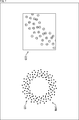
- the microphone array may be configured as shown in FIG.
- a microphone array MA21 in which a plurality of omnidirectional microphone units are arranged in the shape of a flower outline is shown in a portion indicated by an arrow Q31 in FIG.
- each point represents one microphone unit.
- This microphone array MA21 is composed of eight subarrays, and each subarray is composed of 16 microphone units arranged in a ring shape.
- Magnified part of this microphone array MA21 is as shown by arrow Q32.
- each circle represents one microphone unit, and the same numeral is written in the circle representing the microphone unit constituting the same subarray.
- the eight sub-arrays constituting the microphone array MA21 are arranged concentrically and the sub-arrays are arranged adjacent to each other.
- the sub-array consisting of the microphone unit marked with the numeral “2” and the sub-array consisting of the microphone unit marked with the numeral “8” are in the rotation angle with respect to the center position of the microphone array MA21, that is, in the rotation direction.
- the arrangement positions of the microphone units are different, it can be seen that the radii of the subarrays are the same.
- the sub-array consisting of the microphone unit marked with the numeral “3” and the sub-array consisting of the microphone unit marked with the numeral “7” have the same radius but different rotation angles. Also, the sub-array consisting of the microphone unit marked with the numeral “4” and the sub-array consisting of the microphone unit marked with the numeral “6” have the same radius, although the rotation angles are different.
- Such a microphone array MA21 has the above-described features F1 to F3.
- the microphone array MA21 is also referred to as a flower-shaped microphone array.
- the microphone array to which the present technology is applied may be configured as shown in FIGS. 6, 7, and 8, for example.
- a microphone array MA31 formed by arranging a plurality of omnidirectional microphone units so as to have a substantially vortex shape is shown.
- each point represents one microphone unit.
- the microphone array MA31 is composed of eight subarrays, and each subarray has the above-described feature F1.
- Each subarray is composed of 16 microphone units arranged in an annular shape.
- Magnified part of microphone array MA31 is as shown by arrow Q42.
- each circle represents one microphone unit, and the same number is written in the circle representing the microphone unit constituting the same subarray.
- the eight subarrays constituting the microphone array MA31 are arranged concentrically, and the rotation angle of the subarray when each subarray is arranged is randomly determined.
- a portion indicated by an arrow Q51 in FIG. 7 shows a microphone array MA41 formed by arranging a plurality of omnidirectional microphone units in a substantially vortex shape.
- each point represents one microphone unit.
- the microphone array MA41 is composed of eight subarrays, and each subarray is composed of 16 microphone units arranged in a ring shape.
- Magnified part of this microphone array MA41 is as shown by arrow Q52.
- each circle represents one microphone unit, and the same numeral is written in the circle representing the microphone unit constituting the same subarray.
- the eight sub-arrays constituting the microphone array MA41 are arranged concentrically, and the rotation angle of the sub-array when each sub-array is arranged is determined at random.
- the microphone arrays shown in FIGS. 6 and 7 have the above-described features F1 to F3, although the rotation angle of each sub-array is randomly determined.
- a microphone array is also referred to as a random-shaped microphone array.
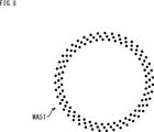
- FIG. 8 shows a microphone array MA51 formed by arranging a plurality of omnidirectional microphone units so as to form a triple ring.
- each point represents one microphone unit.
- the microphone array MA51 is composed of three subarrays, and each subarray is composed of 43 microphone units arranged in a ring shape.
- the three subarrays constituting the microphone array MA51 are arranged concentrically, and when an arbitrary subarray is enlarged or reduced and further rotated, it coincides with other subarrays.
- the region where the value of the Bessel function is zero can be reduced, and the condition number X (k) of the transformation matrix B k can be improved.
- a region where the value of the Bessel function is zero as shown in FIG. 9 can be eliminated.
- the horizontal axis indicates the wave number k
- the vertical axis indicates the order n of the spherical harmonic region.
- the shading in FIG. 9 indicates the value of the Bessel function, and in particular, the black area indicates the area where the value of the Bessel function is 0 (zero). More specifically, the value of the Bessel function shown in FIG. 9 is the maximum value among the values of the Bessel function for each subarray constituting the microphone array.
- the portion indicated by the arrow Q61 indicates the value of the Bessel function in each region corresponding to the wave number k and the order n when the vortex-shaped microphone array is used.
- the part indicated by arrow Q62 indicates the value of the Bessel function in each region corresponding to wave number k and order n when a flower-shaped microphone array is used. Further, the part indicated by the arrow Q63 indicates the value of the Bessel function in each region corresponding to the wave number k and the order n when a random-shaped microphone array is used.
- the conditions of the transformation matrix B k as the distance of the microphone units with each other are projected on the ring closer the better.
- the horizontal axis indicates the frequency
- the vertical axis indicates the condition number X (k) of the transformation matrix B k .
- the condition number X (k) is obtained when the spatial resolution control described later is performed.
- the curves L11 to L14 are the vortex-shaped microphone array MA11 shown in FIG. 3, the flower-shaped microphone array MA21 shown in FIG. 5, the random-shaped microphone array MA31 shown in FIG.
- the condition number X (k) of the flower-shaped microphone array MA21 is the smallest in the entire frequency band.
- the distance between the microphone units is relatively long every 8 microphone units.
- the microphone unit constituting the most central subarray constituting the microphone array MA11 and the microphone unit constituting the farthest subarray are arranged away from each other.
- the distance between the microphone units projected on the ring is longer than in the microphone array MA21, and the condition number X (k) of the vortex-shaped microphone array MA11 is equal to the condition number X ( It is slightly larger than k).
- the condition number X (k) of the microphone array MA31 and the microphone array MA41 is larger than the condition number X (k) of the vortex-shaped microphone array MA11.
- the arrangement of the microphone units in the microphone array can be determined parametrically.
- a parameter indicating the arrangement of each microphone unit of the microphone array is referred to as an arrangement parameter
- a set of a plurality of arrangement parameters is referred to as an arrangement parameter set.
- the arrangement of the microphone units constituting the microphone array is determined by the arrangement parameter set.
- the number S of subarrays is the number of subarrays constituting the microphone array
- the radius r s of the subarray is a distance from the center position of the microphone array to the microphone units constituting the subarray.
- a vector composed of the radius r s of each of the S subarrays is also referred to as a radius vector r sub .
- the sub-array rotation angle ⁇ s is an inclination angle of the sub-array when a predetermined direction viewed from the center position of the microphone array is used as a reference.
- the rotation angle ⁇ s of the subarray is an angle in the rotation direction indicating the position of the subarray in the rotation direction around the center position of the microphone array.
- the center position of the microphone array is set as the center O, and a predetermined reference direction viewed from the center O is set as the reference direction.
- a predetermined reference direction viewed from the center O is set as the reference direction.
- an angle formed between a straight line connecting a microphone unit serving as a predetermined reference constituting the subarray and the center O and the reference direction is set as a rotation angle ⁇ s .
- the reference direction can be the direction of the microphone unit serving as the reference of the subarray closest to the center O.
- the rotation angle ⁇ s of the subarray indicates how much the subarray has rotated the subarray closest to the center O.
- a vector composed of the rotation angle ⁇ s of each of the S subarrays is also referred to as a rotation angle vector ⁇ sub .
- arrangement parameter set P Q opt ⁇ S, r sub , ⁇ sub ⁇ .
- the optimum arrangement parameter depends on the total number Q of microphone units, the operating frequency band [f min , f max ], the diameter D m of the microphone unit, and the upper limit value X max of the condition number X (k).
- the total number Q of microphone units is the number of microphone units constituting the microphone array.
- the total number of microphone units Q determines the number of subarrays constituting the microphone array, that is, the number of subarrays S.
- the value of the number of subarrays S can be 1, 2, 3, 4, 6, 12, or 24.
- the operating frequency band [f min , f max ] is a frequency band from the minimum value f min to the maximum value f max of the frequency of the target sound.
- the number of conditions is considered in this operating frequency band [f min , f max ], and each arrangement parameter is optimized.
- the diameter D m of the microphone unit is the diameter of the microphone unit constituting the microphone array, and this D m is the lower limit of the absolute value of the tolerance of the generalized differential sequence that determines the radius vector r sub .
- radius r s of any two subarrays be radius r i and radius r j (where i ⁇ j).
- the radius r i and the radius r j need to satisfy the following equation (7). This is because, if the condition of Equation (7) is not satisfied, it is impossible to arrange two microphone units having a diameter D m physically side by side even when considering the radius r s and the rotation angle ⁇ s of the subarray. is there.
- the upper limit value X max is the value of the worst (large) condition number X (k) that is allowable within the operating frequency band [f min , f max ].
- condition number X (k) exceeds 100, it becomes ill-conditioned and the inverse matrix becomes unstable.
- the upper limit value Xmax may be about 30 in practice.
- the features F1 to F3 are If the optimum arrangement parameter set P Q opt is determined so as to have the microphone array, a microphone array having an appropriate microphone unit arrangement can be obtained.
- the optimum arrangement parameter set P Q opt is between the operating frequency bands [f min , f max ] under the constraints of the total number of microphone units Q, the diameter D m , and the upper limit value X max . This is obtained by minimizing the average condition number of the transformation matrix B k .
- the search for the placement parameter set P Q opt is guided by an exhaustive search for possible placement parameters. Empirically, a nearly optimal result can be obtained by a metaheuristic optimization method such as differential evolution.
- the order n is always large when the order n is greater than or equal to a certain large order (hereinafter referred to as n 0 (kr)).
- n 0 (kr) a certain large order
- an order n determined with respect to the total number Q of microphone units in the microphone array is N arr .
- the spherical harmonic term up to N arr where the order n is greater than n 0 (kr), that is, the element of the transformation matrix B k does not include reliable information for wavefront reproduction. This is because the value of the Bessel function for the order n is zero or substantially zero for orders n up to N arr greater than n 0 (kr).
- processing for limiting the number of rows (number of rows) of the transformation matrix B k used for calculation to calculate the spherical harmonic coefficient a mn (k) including mode compensation is performed.
- the transformation matrix B n0 k obtained maximum value when the max (r s), the spatial resolution control for the transformation matrix B k of the radius r s of each sub-array, n from first line of the transformation matrix B k It is a matrix including up to 0 (k ⁇ max (r s )) rows.
- the number of rows of the transformation matrix B k used in the calculation is changed to n 0 (k ⁇ max (r s )) by spatial resolution control.
- a transformation matrix B n0 k is obtained as a transformation matrix having a limited number of rows.
- n 0 (k ⁇ max ( r s)) th row of the transformation matrix B k is a row corresponding to the order n 0 (k ⁇ max (r s)).
- n 0 (kr) th ⁇ r
- the value of the threshold th may be 1 or 1.1
- n 0 (kr) th ⁇ r
- the threshold th in Equation (9) may be a real number between 0 and 1, and a value close to 1 is recommended. Specifically, for example, the threshold th is set to 0.95 or the like. Further, in FIGS. 3, 5 to 8, 10 described above, and FIG. 12 described later, the order n 0 (kr s ) defined by the equation (9) is used.
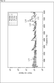
- the horizontal axis indicates the frequency
- the vertical axis indicates the condition number X (k).
- curves L21 to L23 indicate the number of conditions for the annular microphone array, the vortex-shaped microphone array MA11 shown in FIG. 3, and the flower-shaped microphone array MA21 shown in FIG.
- condition number X (k) of the transformation matrix B k is large in the low frequency band for any microphone array.
- This phenomenon is caused by linear dependence due to redundant rows of the transformation matrix B k , and the microphone array to which the present technology is applied can be dealt with by spatial resolution control or appropriate matrix regularization.
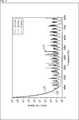
- the condition number X (k) of the transformation matrix B n0 k is as shown in FIG. In FIG. 12, the horizontal axis indicates the frequency, and the vertical axis indicates the condition number X (k).
- curves L31 to L33 indicate the number of conditions for the annular microphone array, the vortex-shaped microphone array MA11 shown in FIG. 3, and the flower-shaped microphone array MA21 shown in FIG.
- condition number X (k) of the transformation matrix B n0 k is kept small in the low frequency band for any microphone array as compared to the example of FIG.
- condition number X (k) is large depending on the frequency.
- Such deterioration of the conditions of the annular microphone array is an inherent property caused by the value of the Bessel function being zero, and cannot be solved by spatial resolution control or matrix regularization.
- condition number X (k) is 30 or less at most frequencies. From this result, it can be seen that better condition number X (k) can be obtained and error tolerance is improved by performing spatial resolution control on a microphone array with an appropriate microphone unit arrangement.
- Such a recording system and playback system are configured as shown in FIG.
- the recording system is constituted by a microphone array 11 and a recording device 12, and the reproduction system is constituted by a reproduction device 13 and a speaker array 14.
- the microphone array 11 may be a part of the recording device 12, and the speaker array 14 may be a part of the playback device 13.
- a sound wavefront is recorded by a microphone array 11 composed of a plurality of microphone units, and a multichannel signal, which is a sound signal obtained as a result, is supplied to the recording device 12. That is, the microphone array 11 records the wavefront of sound by collecting sound by each microphone unit, and outputs a signal composed of a sound signal obtained by collecting sound by each microphone unit as a multi-channel signal.
- the microphone array 11 is for recording a sound field, that is, a sound wavefront, and is composed of a plurality of subarrays. Each subarray is composed of a plurality of microphone units.
- the microphone array 11 is a microphone array having the above-described features F1 to F3 such as those shown in FIGS. 3 and 5 to 8, and the microphone unit constituting the microphone array 11 is an omnidirectional microphone. Is done.
- the recording device 12 calculates a spherical harmonic coefficient a mn (k) based on the multichannel signal supplied from the microphone array 11 and supplies the spherical harmonic coefficient a mn (k) to the playback device 13.
- the recording device 12 includes an input unit 21, a time frequency analysis unit 22, a parameter holding unit 23, a spatial resolution control unit 24, and a spherical harmonic coefficient calculation unit 25.
- the input unit 21 converts the analog multi-channel signal into a digital signal by performing AD (Analog-to-Digital) conversion on the multi-channel signal supplied from the microphone array 11, and sends it to the time-frequency analysis unit 22. Supply.
- AD Analog-to-Digital
- the time-frequency analysis unit 22 performs a short-time Fourier transform (STFT) on the multi-channel signal supplied from the input unit 21 and calculates a spherical harmonic coefficient from the resulting time-frequency spectrum. To the unit 25.
- the time frequency spectrum obtained by the time frequency analysis unit 22 corresponds to the sound pressure p k (r l , ⁇ l , ⁇ l ) shown in the equation (4).
- the parameter holding unit 23 is based on, for example, the total number Q of microphone units given in advance, the operating frequency band [f min , f max ], the diameter D m of the microphone unit, and the upper limit value X max of the condition number X (k). It holds the determined placement parameter set P Q opt .
- the microphone array 11 is a microphone array having a shape determined by the arrangement parameter set P Q opt determined in this way, and the parameter holding unit 23 holds the arrangement parameter set P Q opt for the microphone array 11.
- the arrangement parameter set P Q opt is geometric information indicating the arrangement of the microphone units of the microphone array 11.
- the parameter holding unit 23 supplies the held arrangement parameter set P Q opt to the spatial resolution control unit 24 and the spherical harmonic coefficient calculation unit 25.
- the spatial resolution control unit 24 performs spatial resolution control based on the arrangement parameter set P Q opt supplied from the parameter holding unit 23.
- the spatial resolution control unit 24 performs, for example, the above-described formula (for each frequency, that is, for each wave number k, based on the radius max (r s ) of the subarray constituting the microphone array 11 determined with respect to the arrangement parameter set P Q opt . 9) etc., to calculate (determine) the order n 0 (k ⁇ max (r s )). Then, the spatial resolution control unit 24 supplies the degree n 0 (k ⁇ max (r s )) thus obtained to the spherical harmonic coefficient calculation unit 25, and instructs the limitation of the number of rows of the transformation matrix B k. To do.
- the spherical harmonic coefficient calculation unit 25 includes the time frequency spectrum supplied from the time frequency analysis unit 22, the arrangement parameter set P Q opt supplied from the parameter holding unit 23, and the order n 0 (supplied from the spatial resolution control unit 24.
- the spherical harmonic coefficient a mn (k) is calculated based on k ⁇ max (r s )).
- the spherical harmonic coefficient calculation unit 25 generates a transformation matrix B n0 k with a limited number of rows in accordance with instructions from the spatial resolution control unit 24. Specifically, the spherical harmonic coefficient calculator 25 calculates n 0 (k ⁇ max (r s) from the first row of the transformation parameter B k determined for the arrangement parameter set P Q opt , that is, the microphone unit arrangement of the microphone array 11. )) A matrix including up to the line is generated as a transformation matrix B n0 k which is a final transformation matrix.
- This transformation matrix B n0 k is based on the arrangement parameter set P Q opt which is the geometric information of the microphone array 11 and the order n 0 (k ⁇ max (r s )) which is the output of the spatial resolution control unit 24. For each wave number k, that is, for each STFT bin.
- the spherical harmonic coefficient calculation unit 25 performs a calculation similar to the above-described formula (3) based on the generalized inverse matrix obtained for the transformation matrix B n0 k and the time-frequency spectrum, and the spherical harmonic coefficient a mn ( k) is calculated.
- the spherical harmonic coefficient calculation unit 25 uses a Moore-Penrose pseudo inverse matrix as a generalized inverse matrix of the transformation matrix B n0 k . That, Moore on the transformation matrix B n0 k - pseudo-inverse of Penrose is calculated as the generalized inverse matrix of the transformation matrix B n0 k.
- the spherical harmonic coefficient calculation unit 25 performs a calculation similar to the above-described equation (3). In this calculation, spherical harmonic transformation (SHT (Spherical Harmonic Transform)) and mode compensation are simultaneously performed.
- SHT Spherical Harmonic Transform
- the mode compensation here is a process corresponding to the division of p k (r, ⁇ q , ⁇ q ) Y * m n ( ⁇ q , ⁇ q ) by b n (kr) in equation (1), that is, This is a process of dividing the time-frequency spectrum subjected to spherical harmonic transformation by the mode function (Bessel function).
- the spherical harmonic coefficient calculation unit 25 is provided with a processing block that performs spherical harmonic transformation and a processing block that performs mode compensation. Then, in the processing block that performs spherical harmonic transformation, spherical harmonic transformation is performed on the time frequency spectrum, and in the processing block that performs mode compensation, division by a mode function (Bessel function) is performed on the time frequency spectrum subjected to spherical harmonic transformation. Is called. At this time, in spherical harmonic transformation and mode compensation, calculations up to a term determined by the order n 0 (k ⁇ max (r s )) are performed.
- n 0 k ⁇ max (r s )
- the spherical harmonic coefficient calculation unit 25 outputs (transmits) the calculated spherical harmonic coefficient a mn (k) to the reproduction system.
- a drive signal for driving the speaker array 14 is generated based on the spherical harmonic coefficient a mn (k) output from the spherical harmonic coefficient calculator 25, and the wavefront of the sound is reproduced.
- the generation of the drive signal can be realized by correcting the speaker characteristics of the speaker array 14 or other algorithms.
- the playback device 13 of the playback system includes a speaker arrangement information holding unit 31, a drive signal generation unit 32, a time frequency synthesis unit 33, and an output unit 34.
- the speaker arrangement information holding unit 31 holds speaker arrangement information indicating the arrangement of speakers constituting the speaker array 14 and supplies the held speaker arrangement information to the drive signal generation unit 32.
- the drive signal generator 32 receives the spherical harmonic coefficient a mn (k) transmitted from the spherical harmonic coefficient calculator 25, and supplies the received spherical harmonic coefficient a mn (k) from the speaker arrangement information holding unit 31.
- a drive signal is generated on the basis of the speaker arrangement information and supplied to the time-frequency synthesizer 33.
- the calculation of the above-described equation (2) is performed, and a signal indicating the sound pressure p k (r q , ⁇ q , ⁇ q ) is calculated as a drive signal in the time frequency domain.
- the value of the radius of the reproduction area which is a region for reproducing the sound wavefront, is used as the radius r q .
- the spherical harmonic coefficient a mn (k) is multiplied by the Bessel function, that is, the driving signal of the spherical harmonic region is generated, and the spherical harmonic inverse transform (ISHT (Inverse Spherical Harmonic Transform) )) Is performed at the same time, but after the driving signal of the spherical harmonic region is generated, the spherical harmonic inverse transformation may be performed.
- the drive signal generation unit 32 is provided with a processing block for generating a driving signal for the spherical harmonic region and a processing block for performing spherical harmonic inverse transformation.
- the time-frequency synthesizer 33 performs inverse short-time Fourier transform (ISTFT (Inverse Short Time Fourier Transform)) on the drive signal supplied from the drive signal generator 32, and the resulting time-domain drive signal is obtained. This is supplied to the output unit 34.
- ISTFT Inverse Short Time Fourier Transform
- the output unit 34 performs DA (Digital-to-Analog) conversion on the drive signal supplied from the time-frequency synthesis unit 33 and supplies the resulting analog drive signal to the speaker array 14.
- the speaker array 14 reproduces (reproduces) the wavefront of the sound recorded by the recording system by outputting sound based on the drive signal supplied from the output unit 34.
- the speaker array 14 is obtained by arranging linear speaker arrays obtained by arranging the speakers in a linear shape in a rectangular shape, and the area inside the speaker array 14 is a wavefront reproduction area.
- the speaker array 14 may have any shape, that is, speaker arrangement.
- the arrangement parameter set P Q opt is determined in advance by the parameter holding unit 23 or another processing block, and the obtained arrangement parameter set P Q opt is held by the parameter holding unit 23.
- step S ⁇ b> 11 the spatial resolution control unit 24 performs spatial resolution control based on the arrangement parameter set P Q opt supplied from the parameter holding unit 23.
- the spatial resolution control unit 24 supplies to the spherical harmonic coefficient calculation unit 25 calculates the order n 0 by calculating the like above expression (9) (k ⁇ max ( r s)), the transformation matrix B k Indicates a limit on the number of rows in
- step S ⁇ b> 12 the microphone array 11 collects ambient sounds with the microphone unit, and supplies the resulting multi-channel signal to the input unit 21.
- the input unit 21 performs AD conversion on the multichannel signal supplied from the microphone array 11 and supplies the converted signal to the time-frequency analysis unit 22.
- step S13 the time-frequency analysis unit 22 performs a short-time Fourier transform on the multi-channel signal supplied from the input unit 21, and supplies the resulting time-frequency spectrum to the spherical harmonic coefficient calculation unit 25.
- step S ⁇ b> 14 the spherical harmonic coefficient calculation unit 25 calculates the temporal frequency spectrum from the temporal frequency analysis unit 22, the arrangement parameter set P Q opt from the parameter holding unit 23, and the order n 0 (k ⁇ from the spatial resolution control unit 24).
- the spherical harmonic coefficient a mn (k) is calculated based on max (r s )).
- the spherical harmonic coefficient calculation unit 25 generates a transformation matrix B n0 k based on the order n 0 (k ⁇ max (r s )) in accordance with an instruction from the spatial resolution control unit 24, and the transformation matrix B n0 Compute the generalized inverse of k . Then, the spherical harmonic coefficient calculation unit 25 performs the same calculation as that of Expression (3) based on the obtained generalized inverse matrix and the time-frequency spectrum, and calculates the spherical harmonic coefficient a mn (k).
- the spherical harmonic coefficient calculation unit 25 outputs the spherical harmonic coefficient a mn (k) calculated in this way, and the recording process ends.
- the recording system records a wavefront using the microphone array 11 having a shape (microphone unit arrangement) determined with respect to the arrangement parameter set P Q opt , and uses a transformation matrix obtained by performing spatial resolution control. To calculate the spherical harmonic coefficient a mn (k). In this way, it is possible to record a wide-range sound field at a low cost.
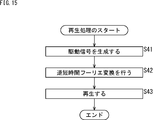
- step S41 the drive signal generation unit 32 generates a drive signal based on the received spherical harmonic coefficient a mn (k) and the speaker arrangement information supplied from the speaker arrangement information holding unit 31, and the time frequency synthesis unit 33.
- the above-described equation (2) is calculated, and a signal indicating the sound pressure p k (r q , ⁇ q , ⁇ q ) is calculated as a drive signal in the time frequency domain.
- step S ⁇ b> 42 the time-frequency synthesis unit 33 performs inverse short-time Fourier transform on the drive signal supplied from the drive signal generation unit 32, and supplies the resulting time-domain drive signal to the output unit 34.
- the output unit 34 performs DA conversion on the drive signal supplied from the time-frequency synthesis unit 33, and supplies the analog drive signal obtained as a result to the speaker array 14.
- step S43 the speaker array 14 reproduces (reproduces) the wavefront of the sound recorded by the recording system by outputting sound based on the drive signal supplied from the output unit 34, and the reproduction process ends.
- the reproduction system generates a drive signal from the received spherical harmonic coefficient a mn (k), and reproduces the sound wavefront based on the drive signal.
- wide-band wavefront reproduction can be realized by reproducing the wavefront based on the spherical harmonic coefficient a mn (k) received from the recording system.
- the above-described series of processing can be executed by hardware or can be executed by software.
- a program constituting the software is installed in the computer.
- the computer includes, for example, a general-purpose personal computer capable of executing various functions by installing a computer incorporated in dedicated hardware and various programs.
- FIG. 16 is a block diagram showing an example of the hardware configuration of a computer that executes the above-described series of processes using a program.
- a CPU Central Processing Unit
- ROM Read Only Memory
- RAM Random Access Memory
- An input / output interface 505 is further connected to the bus 504.
- An input unit 506, an output unit 507, a recording unit 508, a communication unit 509, and a drive 510 are connected to the input / output interface 505.
- the input unit 506 includes a keyboard, a mouse, a microphone array, an image sensor, and the like.
- the output unit 507 includes a display, a speaker array, and the like.
- the recording unit 508 includes a hard disk, a nonvolatile memory, and the like.
- the communication unit 509 includes a network interface or the like.
- the drive 510 drives a removable recording medium 511 such as a magnetic disk, an optical disk, a magneto-optical disk, or a semiconductor memory.
- the CPU 501 loads the program recorded in the recording unit 508 to the RAM 503 via the input / output interface 505 and the bus 504 and executes the program, for example. Is performed.
- the program executed by the computer (CPU 501) can be provided by being recorded in a removable recording medium 511 as a package medium, for example.
- the program can be provided via a wired or wireless transmission medium such as a local area network, the Internet, or digital satellite broadcasting.
- the program can be installed in the recording unit 508 via the input / output interface 505 by attaching the removable recording medium 511 to the drive 510. Further, the program can be received by the communication unit 509 via a wired or wireless transmission medium and installed in the recording unit 508. In addition, the program can be installed in the ROM 502 or the recording unit 508 in advance.
- the program executed by the computer may be a program that is processed in time series in the order described in this specification, or in parallel or at a necessary timing such as when a call is made. It may be a program for processing.
- the present technology can take a cloud computing configuration in which one function is shared by a plurality of devices via a network and is jointly processed.
- each step described in the above flowchart can be executed by one device or can be shared by a plurality of devices.
- the plurality of processes included in the one step can be executed by being shared by a plurality of apparatuses in addition to being executed by one apparatus.
- the present technology can be configured as follows.
- a microphone array for recording a sound field composed of a plurality of subarrays The sub-array is composed of a plurality of microphones and has a discrete rotationally symmetric shape having a predetermined radius, A microphone array in which, when the radii of the plurality of subarrays are arranged into a number sequence, the number sequence becomes a generalized differential number sequence.
- the projected microphones are arranged at equal intervals on the ring.
- the plurality of microphones constituting the microphone array are all omnidirectional microphones, or at least one of the plurality of microphones constituting the microphone array is not an omnidirectional microphone (1) to (4 The microphone array according to any one of the above.
- a spherical harmonic coefficient calculation unit that calculates a spherical harmonic coefficient based on a multichannel signal obtained by collecting a microphone array for sound field recording composed of a plurality of subarrays,
- the sub-array is composed of a plurality of microphones and has a discrete rotationally symmetric shape having a predetermined radius
- a recording apparatus in which, when the radii of the plurality of subarrays are arranged to form a number sequence, the number sequence becomes a generalized differential number sequence.
- the recording apparatus further including a spatial resolution control unit that limits the number of rows of the transformation matrix for mode compensation based on a predetermined order of the spherical harmonic region.
- the spatial resolution control unit determines the predetermined order based on a maximum value of the radius of the plurality of subarrays.
- the spherical harmonic coefficient calculation unit calculates the spherical harmonic coefficient by the mode compensation based on a generalized inverse matrix of the transformation matrix with a limited number of rows and the multichannel signal.
- the recording device A spherical harmonic coefficient is calculated based on a multi-channel signal obtained by collecting sound from a microphone array for recording a sound field composed of a plurality of sub-arrays,
- the sub-array is composed of a plurality of microphones and has a discrete rotationally symmetric shape having a predetermined radius,
- a recording method in which, when the radii of the plurality of subarrays are arranged to form a number sequence, the number sequence becomes a generalized differential number sequence.
Landscapes
- Health & Medical Sciences (AREA)
- Otolaryngology (AREA)
- Physics & Mathematics (AREA)
- Engineering & Computer Science (AREA)
- Acoustics & Sound (AREA)
- Signal Processing (AREA)
- General Health & Medical Sciences (AREA)
- Obtaining Desirable Characteristics In Audible-Bandwidth Transducers (AREA)
- Circuit For Audible Band Transducer (AREA)
Abstract
本技術は、低コストで広帯域な音場収録を行うことができるようにするマイクロホンアレイ、収録装置および方法、並びにプログラムに関する。 マイクロホンアレイは、複数のサブアレイから構成される音場収録のためのものである。また、サブアレイは、複数のマイクロホンから構成されるとともに所定の半径を有する離散的な回転対称の形状であり、複数のサブアレイの半径を並べて数列としたときに、その数列が一般化等差数列となる。本技術はマイクロホンアレイや収録装置などに適用することができる。
Description
本技術は、マイクロホンアレイ、収録装置および方法、並びにプログラムに関し、特に、低コストで広帯域な音場収録を行うことができるようにしたマイクロホンアレイ、収録装置および方法、並びにプログラムに関する。
近年、音の波面の収録や再現はオーディオ産業において一般的になってきている。波面合成・復元技術では、空間に配置されたオブジェクトの音像定位や空間的なノイズキャンセリングが可能であり、従来のマルチチャネル再生手法と比較して、より一層リアルな音響体験を提供することができる。
例えば無指向性マイクロホンによって構成されたオープン型の環状マイクロホンアレイは、様々なアプリケーションで利用されている。
しかし、このような環状マイクロホンアレイのマイクロホン配置のデザインは、広い周波数帯域の波面(音場)を収録するのには適していない。その理由は、環状マイクロホンアレイを用いた場合、収録した音の波面の球面調和係数を得るためのベッセル関数として知られるモード関数が、所定の周波数帯域においてゼロとなることに起因する。
そこで、例えば複数のマイクロホンを二重またはそれ以上の多重の環状に配置したり、カーディオイド指向性マイクロホンを使用したり(例えば、非特許文献1参照)、剛体バッフルを使用したりして、モード関数がゼロとなる領域を少なくすることが考えられる。
また、それ以外にも無指向性マイクロホンに基づくアレイ収録手法もいくつか存在する(例えば、非特許文献2、非特許文献3、および特許文献1乃至特許文献3参照)。
G. Huang, "Design of robust concentric circular differential microphone arrays", The Journal of the Acoustical Society of America, 2017.
Z. Prime and C. Doolan, "A comparison of popular beamforming arrays", Proceedings of Acoustics 2013 Victor Harbor: Science Technology and Amenity, Annual Conference of the Australian Acoustical Society, 2013.
D. Mandal, S. P. Ghoshal and A. K. Bhattacharjee, "Concentric circular antenna array synthesis using Particle Swarm Optimization with Constriction Factor Approach", Indian Antenna Week: A Workshop on Advanced Antenna Technology, 2010.
しかしながら、上述した技術では、低コストで広帯域な音場収録を行うことは困難であった。
例えば複数のマイクロホンを多重の環状に配置したり、カーディオイド指向性マイクロホンを使用したり、剛体バッフルを使用したりするアプローチでは、多くの状況において、十分広い周波数帯域の音場収録を行うことができなかったり、コスト面や物理的な制約によって実現が困難であったりする。
また、非特許文献2や特許文献1乃至特許文献3に記載の技術はビームフォーミング向けにサイドローブを小さくするためのものであり、非特許文献3に記載の技術は音を対象としていないものである。そのため、これらのアレイ収録手法は波面再現のための収録には相応しくない。
本技術は、このような状況に鑑みてなされたものであり、低コストで広帯域な音場収録を行うことができるようにするものである。
本技術の第1の側面のマイクロホンアレイは、複数のサブアレイから構成される音場収録のためのマイクロホンアレイであって、前記サブアレイは、複数のマイクロホンから構成されるとともに所定の半径を有する離散的な回転対称の形状であり、前記複数の前記サブアレイの前記半径を並べて数列としたときに、その前記数列が一般化等差数列となる。
本技術の第1の側面においては、マイクロホンアレイは、複数のサブアレイから構成される音場収録のためのマイクロホンアレイとされ、前記サブアレイは、複数のマイクロホンから構成されるとともに所定の半径を有する離散的な回転対称の形状とされ、前記複数の前記サブアレイの前記半径を並べて数列としたときに、その前記数列が一般化等差数列となるようになされる。
本技術の第2の側面の収録装置は、複数のサブアレイから構成される音場収録のためのマイクロホンアレイが収音することで得られたマルチチャネル信号に基づいて球面調和係数を算出する球面調和係数算出部を備え、前記サブアレイは、複数のマイクロホンから構成されるとともに所定の半径を有する離散的な回転対称の形状であり、前記複数の前記サブアレイの前記半径を並べて数列としたときに、その前記数列が一般化等差数列となる。
本技術の第2の側面の収録方法またはプログラムは、本技術の第2の側面の収録装置に対応する収録方法またはプログラムである。
本技術の第2の側面においては、複数のサブアレイから構成される音場収録のためのマイクロホンアレイが収音することで得られたマルチチャネル信号に基づいて球面調和係数が算出される。また、前記サブアレイは、複数のマイクロホンから構成されるとともに所定の半径を有する離散的な回転対称の形状とされ、前記複数の前記サブアレイの前記半径を並べて数列としたときに、その前記数列が一般化等差数列となるようになされる。
本技術の第1の側面および第2の側面によれば、低コストで広帯域な音場収録を行うことができる。
なお、ここに記載された効果は必ずしも限定されるものではなく、本開示中に記載された何れかの効果であってもよい。
〈第1の実施の形態〉
〈本技術について〉
本技術は、マイクロホンアレイの幾何学的配置により、平面音場の収録および再現を広い周波数帯域にわたって実現することができるようにするものである。
〈本技術について〉
本技術は、マイクロホンアレイの幾何学的配置により、平面音場の収録および再現を広い周波数帯域にわたって実現することができるようにするものである。
本技術では、マイクロホンアレイにおける各マイクロホン、すなわちマイクユニットの配置をパラメトリックに決定することができる。なお、マイクユニットの配置を定める配置パラメータは、様々なユースケースに合わせて適切に決定すればよい。例えばマイクロホンアレイは、複数のマイクロホンからなる、離散的な回転対称形状の複数のサブアレイから構成され、それらのサブアレイの形状は類似したものとされる。
このような本技術によれば、マイクロホンの設置誤差や製造ばらつきなどの誤差に対する頑健性を向上させ、より広い周波数帯域を対象として音場収録と再現、つまり音の波面の収録と再現を行うことができる。また、マイクロホンのコストやSN比(Signal to Noise ratio)などのマイクユニット性能要件も容易に満足することができるようになる。
以下、図面を参照して、本技術を適用した実施の形態について説明する。
本技術を適用した音場収録のためのマイクロホンアレイは、基本的には各マイクロホンがマイクロホンアレイの中心を囲むように2次元平面上に配置された略環状のマイクロホンアレイとされる。しかし、これに限らず、マイクロホンが3次元空間上に配置された、3次元の音場を収録するためのマイクロホンアレイであってもよい。
すなわち、マイクロホンが3次元空間上に配置される場合には、例えば本技術を適用したマイクロホンアレイは、各マイクロホンがマイクロホンアレイの中心を囲むように3次元空間上に配置された、略球状のマイクロホンアレイなどとすることができる。
以下では、本技術を適用したマイクロホンアレイは、各マイクロホンを2次元平面上に配置して得られる構造のものであるとして説明を続ける。
マイクロホンアレイで収録された音の波面(音場)の信号を球面調和領域の信号に変換する際にベッセル関数のゼロ点があると、正確に変換を行うことができない周波数帯域が発生する。
例えばマイクロホンアレイが単一の環状である場合や二重の環状である場合、図1に示すようにモード関数、すなわちベッセル関数の値がゼロとなる周波数帯域が生じる。
なお、図1において横軸は波数を示しており、縦軸は球面調和領域の次数を示している。また、図1における濃淡はベッセル関数の値を示しており、特に黒い部分の領域はベッセル関数の値が0(ゼロ)である領域を示している。
より詳細には、図1で示すベッセル関数の値は、マイクロホンアレイを構成する各マイクロホンについてのベッセル関数の値のうちの最大値となっている。各マイクロホンのベッセル関数の値は、マイクロホンアレイの中心からマイクロホンまでの距離によって変化する。
図1では、矢印Q11に示す部分は、マイクロホンアレイが単一の環状である場合における、波数および次数に対応する各領域におけるベッセル関数の値を示している。この例では、例えば矢印A11に示す領域など、多くの領域においてベッセル関数がゼロとなっており、正確に波面を収録および再現することができない周波数帯域が発生してしまうことが分かる。
これに対して、矢印Q12に示す部分は、マイクロホンアレイが二重の環状である場合における、波数および次数に対応する各領域におけるベッセル関数の値を示している。この例では、矢印A11に示した例と比較するとベッセル関数がゼロとなる領域は少なくなっていることが分かる。しかし、ベッセル関数がゼロに近い小さな値は多数存在しており、これにより波面の収録および再現に悪影響を及ぼすおそれがある。
同様に例えば図2に示すように、マイクロホンアレイを構成するマイクロホンとして、カーディオイド指向性マイクロホンを用いることでベッセル関数がゼロとなる領域を少なくすることができるがコストが高くなってしまう。
なお、図2において横軸は波数を示しており、縦軸は球面調和領域の次数を示している。また、図2における濃淡はモード関数、つまりベッセル関数の値を示しており、特に黒い部分の領域はベッセル関数の値が0(ゼロ)である領域を示している。より詳細には、図2で示すベッセル関数の値は、マイクロホンアレイを構成する各マイクロホンについてのベッセル関数の値のうちの最大値となっている。
図2に示す例では、各波数において、ある次数以下では、図1に示した例と比較してベッセル関数がゼロとなる領域が殆どない状態となっているが、カーディオイド指向性マイクロホンを用いるとコストが高くなってしまう。
また、これまでに無指向性マイクロホンに基づくアレイ収録手法もいくつか提案されているが、それらの手法は、音の波面再現のための収録に相応しいものではなかった。
一方で、単純にベッセル関数のゼロ点を避ける方法もある。例えば二重の環状のマイクロホンアレイを用いる場合に、一方の環状のマイクロホンアレイにおいてはベッセル関数の値がゼロとなるときでも、他方の環状のマイクロホンアレイではベッセル関数の値がゼロでないときには、そのゼロでないベッセル関数の値を用いることもできる。しかし、この方法では十分な精度で球面調和領域の信号を得ることができない。
一般的に、マイクロホン固有のセンサ雑音や環境雑音を避けることはできない。さらに、マイクロホンの設置誤差や製造ばらつきによって、マイクロホンの実際の配置位置と理論的に設計した座標により示される配置位置とを正確に一致させることは難しい。
これらの雑音や設置誤差、製造ばらつき等の誤差は、収録した波面を再現する処理を行う際に、ベッセル関数の小さな値による割り算によって拡大されてしまうため、数値計算に悪影響を及ぼす。したがって、ベッセル関数のゼロ点を避ける手法だけではなく、マイクロホン配置の設計時に誤差耐性の最適化や解析を行うことが重要である。
換言すれば、より正確な波面の収録や再現には、誤差耐性の高さ、つまり誤差に対する頑健性が必要である。特に、コスト面を考えると、物理的制約や信号処理のしやすさも考慮して、必要最小限の無指向性マイクロホンの使用を前提とした、誤差耐性の高いマイクロホン配置のデザインが必要となる。
ここで、音の波面、つまり音場の収録と再現について説明する。なお、以下ではマイクロホンアレイを構成するマイクロホンを、特にマイクユニットとも称することとする。
例えば音の波面の収録と再現は、波面の球面調和係数を得ることにより実現することができる。
具体的には、波面の収録に環状マイクロホンアレイを用いる場合、サンプリング定理の条件を満たすならば、球面調和係数amn(k)は波面の音圧pk(r,θq,φq)をQ個の各点でサンプリングすることによって得られる。
また、音圧pk(r,θq,φq)に含まれている、環状マイクロホンアレイの半径rに依存する成分は、半径rに依存する成分であるbn(kr)での割り算によって除去される。
すなわち、球面調和係数amn(k)は次式(1)により得ることができる。

なお、式(1)においてnおよびmは球面調和領域の次数を示しており、qは音圧のサンプリングを行うQ個の各点を示すインデクス(但し、q=0,…,Q-1)であり、以下ではインデクスqにより示されるサンプリング点を点qとも記すこととする。
また、kは波数を示しており、rは環状マイクロホンアレイの半径、つまり環状マイクロホンアレイの中心位置からマイクユニットまでの距離を示している。θqおよびφqは、それぞれ点qに位置するマイクユニットが向けられた方向を示す仰角および方位角を示している。
さらに、式(1)において、fは周波数を示しており、csは音速を示しており、bn(kr)はモード関数を示しており、Y*m
n(θq,φq)は球面調和基底を示している。特に、環状マイクロホンアレイを無指向性マイクロホンで構成した場合、モード関数であるbn(kr)は球ベッセル関数となる。以下では、bn(kr)を単にベッセル関数とも称することとする。また、球面調和基底Y*m
n(θq,φq)における「*」は複素共役を示している。
なお、環状マイクロホンアレイを無指向性マイクロホンで構成した場合の例については、例えば「B. Rafaely, Fundamentals of Spherical Array Processing, Springer, 2015.」(以下、参照文献1とも称する)などに詳細に記載されている。
また、式(1)の演算処理、特に式(1)におけるベッセル関数bn(kr)による除算処理はモード補償(mode compensation)として引用されることもある。なお、モード補償については、例えば「D. P. Jarrett, E. A. Habets and P. A. Naylor, Theory and Applications of Spherical Microphone Array Processing, Springer, 2017.」(以下、参照文献2とも称する)などに詳細に記載されている。
環状マイクロホンアレイにより各点qにおいて収音を行い、それらの点qにおける音圧pk(r,θq,φq)を得ることで音の波面を収録すると、得られた音圧pk(r,θq,φq)から式(1)により球面調和係数amn(k)を得ることができる。また、このようにして得られた球面調和係数amn(k)を再生システムに伝送すれば、再生システムでは球面調和係数amn(k)を用いて、音の波面(音場)を再現することができる。
ところで、式(1)におけるベッセル関数bn(kr)の値がゼロに近い場合、Bessel zero problemと呼ばれる数値的な問題が発生する。すなわち、以下において説明するように、ベッセル関数bn(kr)の値がゼロに近くなると、球面調和係数amn(k)を得るための変換行列の条件数が大きくなり、正確な球面調和係数amn(k)を得ることができなくなってしまう。
環状マイクロホンアレイを構成する各マイクユニットが同じ環の上にない場合、すなわち各点qに配置されたマイクユニットの半径rqが異なる場合、点qにおいてサンプリングされた音圧pk(rq,θq,φq)は、次式(2)により表される。なお、マイクユニットの半径rqは、環状マイクロホンアレイの中心からそのマイクユニットまでの距離、つまり点qまでの距離である。

この場合、各次数および波数の球面調和係数amn(k)は各点qで得られた音圧pk(rq,θq,φq)の分布、つまり音圧pk(rq,θq,φq)からなるベクトルpkに、変換行列Bkの一般化逆行列(pseudo-inverse matrix)であるB+
kをかけることにより得ることができる。
すなわち、例えば次式(3)の計算を行うことで、波数kについての球面調和係数amn(k)からなるベクトルa(k)を得ることができる。

式(3)においてB+
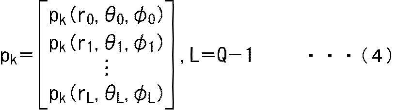
kは変換行列Bkの一般化逆行列を示している。なお、ベクトルpkは、以下の式(4)に示すように各点lの音圧pk(rl,θl,φl)からなるベクトルであり、ここではl=0,…,L,L=Q-1である。つまり、式(4)では音圧のサンプリング点を示すインデクスがlとされており、このlは上述したqに対応する。
また、変換行列Bkは、以下の式(5)に示すように、各点lの次数n(但し、0≦n≦N)についてのベッセル関数bn(krl)と球面調和関数Ym
n(θl,φl)との積を要素とする行列である。

上述した式(3)では、モード補償の割り算では、式(1)に示したY*m
n(θq,φq)/bn(kr)が一般化逆行列B+
kに置き換えられている。この式(3)から正確な球面調和係数amn(k)を得るためには、変換行列Bkは可逆であり、かつ悪条件を避けなければならない。ここで、変換行列Bkが良条件であるか、または悪条件であるかは、例えば変換行列Bkについての条件数により評価することができる。
変換行列Bkの最小特異値および最大特異値を、それぞれσmin(Bk)およびσmax(Bk)とすると、変換行列Bkの条件数X(k)は、次式(6)により得ることができる。

式(3)の計算を行う場合、観測されたベクトル、すなわちここではベクトルpkに誤差が含まれているときには、その誤差は条件数をX(k)とするとX(k)倍だけ増加する。
したがって、変換行列Bkの条件数X(k)は小さい方がよく、条件数X(k)が小さいことは強い誤差耐性を持つこと、すなわち誤差に対する頑健性が高いことを意味する。アプリケーションにもよるが経験的に条件数が100を超える場合、その行列は悪条件となる。なお、条件数に基づく環状マイクロホンアレイや球状マイクロホンアレイの誤差耐性解析については、例えば上述した参照文献1に詳細に記載されている。
以上のように、式(3)の計算によって音の波面を再現するための球面調和係数amn(k)を得ることができるが、マイクロホンアレイを構成する各マイクユニットの配置と、球面調和領域の次数nの最大値(最大次数)とを適切に設定することで、良条件の変換行列Bkを得ることができる。
そこで本技術では、マイクユニットの配置と、球面調和領域の最大次数とを適切に設定することで、少ない本数の無指向性のマイクユニットを用いて、すなわち低コストで、広い周波数帯域において高い雑音耐性(誤差耐性)を実現することができるようにした。
特に、本技術を適用した波面の収録および再現(再生)は、以下において説明する特徴を有するパラメトリックなマイクロホンアレイデザインと、周波数に依存する空間分解能制御とによって実現される。
例えば本技術を適用したマイクロホンアレイは、以下の特徴F1乃至特徴F3を有している。すなわち、本技術を適用したマイクロホンアレイは、以下の特徴F1乃至特徴F3に基づくデザインとされる。
(特徴F1)
マイクロホンアレイは幾何学的に類似した複数のサブアレイにより構成され、各サブアレイは離散的な回転対称となっている
(特徴F2)
マイクロホンアレイ中心から見てマイクユニットが等角度で分布している
(特徴F3)
各サブアレイの半径を並べて数列としたときに一般化等差数列となる
マイクロホンアレイは幾何学的に類似した複数のサブアレイにより構成され、各サブアレイは離散的な回転対称となっている
(特徴F2)
マイクロホンアレイ中心から見てマイクユニットが等角度で分布している
(特徴F3)
各サブアレイの半径を並べて数列としたときに一般化等差数列となる
本技術を適用したマイクロホンアレイは複数のサブアレイから構成され、各サブアレイは複数のマイクユニットから構成される。
なお、マイクロホンアレイが1つのサブアレイから構成されるようにしてもよく、またサブアレイが1つのマイクユニットから構成されるようにしてもよい。
さらに、マイクロホンアレイを構成するマイクユニットは、基本的には全て無指向性マイクロホンとされるが、一部のマイクユニットが無指向性ではないマイクロホンとされるようにしてもよい。
上述した特徴F1は、マイクロホンアレイが複数のサブアレイから構成されるときには、それらの全サブアレイは幾何学的に類似した形状(マイクユニット配置)となることである。ここで、サブアレイが幾何学的に類似しているとは、サブアレイを構成するマイクユニットの配置が類似していることである。
例えば2つのサブアレイが幾何学的に類似しているとは、一方のサブアレイに対して拡大、縮小、回転、および反転のうちの少なくとも何れか1つの操作を行ったときに他方のサブアレイと一致することをいう。
ここでいう一致するとは、拡大等の操作が一方のサブアレイに対してなされると、その操作後のサブアレイの各マイクユニットの配置位置が、他方のサブアレイを構成する各マイクユニットの配置位置と一致することである。この場合、各サブアレイの中心位置は、マイクロホンアレイの中心位置と一致していることになる。
また、各サブアレイは離散的な回転対称の形状のアレイとされる。すなわち、サブアレイは、任意の角度だけ回転させても常に同じ形状となる連続的な回転対称ではないが、サブアレイの中心位置、つまりマイクロホンアレイの中心位置を中心として所定の角度だけ回転させたときに、回転前後のサブアレイが一致する離散的な回転対称となっている。マイクロホンアレイでは、各サブアレイが離散的な回転対称であることから、周波数特性をフラットにすることができる。
さらに、各サブアレイは、所定の半径を有するアレイとなっている。特に、ここではサブアレイを構成する全マイクユニットの半径は同じであり、その半径がサブアレイの半径となるものとする。マイクユニットの半径は、サブアレイの中心位置、すなわちマイクロホンアレイの中心位置からそのマイクユニットまでの距離である。
したがって、サブアレイを構成する複数のマイクユニットのそれぞれは、マイクロホンアレイの中心位置、つまりサブアレイの中心位置から、そのサブアレイの半径の距離の位置に配置されていることになる。
特徴F2は、マイクロホンアレイを構成する全てのマイクユニットを、マイクロホンアレイの中心位置を中心とする1つの環上、つまり円周上に、放射状に射影すると、その環上において、射影されたマイクユニットが均一に分布することである。すなわち環上において、射影されたマイクユニットが等間隔で並ぶようになることである。
ここで、マイクユニットの環上における射影位置は、そのマイクユニット、およびマイクロホンアレイの中心位置を結ぶ(通る)直線と、射影先となる環(円)との交点位置となる。すなわち、マイクロホンアレイの中心位置から見たときの環上におけるマイクユニットの位置が、そのマイクユニットの射影先の位置となる。
このような特徴F2をもたせることで、波面の収録後に複雑な信号処理を行う必要がなくなる。このような性質による複雑な信号処理の省略については、例えば上述した参照文献1に詳細に記載されている。
さらに特徴F3は、マイクロホンアレイを構成する複数のサブアレイのなかに互いに半径の異なるものがあり、マイクロホンアレイを構成する全てのサブアレイの半径の値を昇順または降順に並べて数列とした場合に、その数列が一般化等差数列となることである。
換言すれば、特徴F3はマイクロホンアレイの中心から外側に向かう方向、つまり中心から遠ざかる方向において、マイクユニットが一般化等差数列の公差に対応する間隔で配置されていることである。
例えば「Z. Prime and C. Doolan, "A comparison of popular beamforming arrays", Proceedings of Acoustics 2013 Victor Harbor: Science Technology and Amenity, Annual Conference of the Australian Acoustical Society, 2013.」や米国特許第6205224号明細書には、対数や幾何学的な数列により定まる半径でマイクユニットを配置する手法が開示されている。
しかし、周波数ごとに空間分解能制御を行う場合、これらの手法よりも本技術のように一般化等差数列でサブアレイの半径を決定した方が、ベッセル関数の値がゼロまたは略ゼロとなる領域の低減効果がより高くなる。すなわち、変換行列Bkの条件数X(k)がより小さくなる。
また、マイクロホンアレイを特徴F1と特徴F2を有するデザインとすれば、いくつかのサブアレイを用いることで、要求に合わせたスケーラブルな利用が可能となる。
マイクロホンアレイを構成するサブアレイとして、幾何学的に類似するいくつかのサブアレイを用いるとする。この場合、例えば使用可能なマイクユニットの数が十分多いときには、3つのサブアレイによりマイクロホンアレイを構成し、使用可能なマイクユニットの数が少ないときには、2つのサブアレイによりマイクロホンアレイを構成するといったようにスケーラブルな利用が可能である。
さらに、マイクロホンアレイの変換行列Bkは周波数、すなわち波数kに依存しており、変換の空間分解能は、正確な音場情報を取得するために動作周波数帯域の周波数ごとに適切に設定される。
例えば式(3)の計算により球面調和係数amn(k)を得ようとする場合、一般的には、より大きい次数nの項まで計算を行うと、より高い空間分解能で、より正確な球面調和係数amn(k)を得ることができる。しかし、次数nがマイクユニットの配置等により定まる所定の次数以上である成分については、ベッセル関数の値が0または0に近い値となる。
そこで、本技術では、所定の大きさ以上である各次数nについて、それらの次数nに対応する行を変換行列Bkから除外(除去)させる処理を空間分解能制御として行うことで、変換行列Bkの条件数を向上させるようにした。換言すれば、演算に用いる次数nを制限する、つまり変換行列Bkの行数を制限するようにした。
本技術の利点は、特に、必要最小限の本数の無指向性のマイクユニットを用いて、高い誤差耐性で広帯域の音場(波面)を収録できることである。
空間分解能制御は誤差耐性を向上させるだけでなく計算量も削減することができる。
また、マイクロホンアレイを複数のサブアレイからなる構成とすることで、小さなマイクユニットを使用することなく、角度方向のサンプリング密度を高くすることができる。これは、例えば複数のサブアレイを並べることで、マイクユニットを単一の環状に並べたときよりも、マイクロホンアレイの中心位置を中心とする環上に、放射状にマイクユニットを射影したときの環上における射影されたマイクユニットの密度をより高くすることができるからである。
さらに、本技術を適用したマイクロホンアレイは、自己相似性を持つ、すなわちフラクタルな形状である。そのため、本技術では少ない本数のマイクユニットしか使用できない場合でもマイクロホンアレイを構成可能なスケーラビリティを持つ。換言すれば、上述したようにスケーラブルな利用が可能である。
〈マイクロホンアレイの構成例〉
続いて、本技術を適用したマイクロホンアレイのより具体的な構成例について説明する。図3は、本技術を適用したマイクロホンアレイの一実施の形態の構成例を示す図である。
続いて、本技術を適用したマイクロホンアレイのより具体的な構成例について説明する。図3は、本技術を適用したマイクロホンアレイの一実施の形態の構成例を示す図である。
図3に示すマイクロホンアレイMA11は、複数の無指向性のマイクユニットからなる渦形状のマイクロホンアレイである。なお、図3において各点は1つのマイクユニットを表している。
この例では、マイクロホンアレイMA11は128個のマイクユニットから構成されており、それらのマイクユニットが渦形状に配置されている。
マイクロホンアレイMA11では16個のマイクユニットにより1つのサブアレイが構成されている。すなわち、マイクロホンアレイMA11は互いに半径の異なる8個のサブアレイにより構成されており、それらの8個のサブアレイは同心円状に配置されている。
例えば環状に配置された16個のマイクユニットからなる部分が1つのサブアレイSA11とされており、同様に環状に配置された16個のマイクユニットからなる部分が1つのサブアレイSA12とされている。
また、マイクロホンアレイMA11は、上述した特徴F1乃至特徴F3を有している。
例えばマイクロホンアレイMA11を構成する各サブアレイはスケールと回転角度のみが異なる形状となっている。具体的には、例えばサブアレイSA11を拡大して所定角度だけ回転させると、サブアレイSA12と一致する。
また、各サブアレイでは、中心位置O11を中心としてマイクユニットが円環状に並べられており、これによりサブアレイは離散的な回転対称の形状となっている。
このマイクロホンアレイMA11の一部分を拡大すると、図4に示すようになる。なお、図4において各円は1つのマイクユニットを表している。また、図4では、同じサブアレイを構成するマイクユニットを表す円内には同じ数字が記されている。
図4に示す例では、例えば数字「1」が記されたマイクユニットは、図3に示したサブアレイSA11を構成しており、数字「8」が記されたマイクユニットは、図3に示したサブアレイSA12を構成している。
特に、この例では各サブアレイが互いに隣接して配置されており、それらのサブアレイの半径からなる数列が一般化した等差数列となることが分かる。すなわち、どのサブアレイについても、互いに隣接するサブアレイ同士の半径の差は、公差に対応する予め定められたいくつかの値のうちの何れかの値となる。
なお、以下では図3に示したマイクロホンアレイMA11を、特に渦形状のマイクロホンアレイとも称することとする。
また、ここではマイクロホンアレイが8個のサブアレイから構成され、それらのサブアレイが16個のマイクユニットから構成される例について説明した。しかし、その他、例えばマイクロホンアレイが4個のサブアレイから構成され、各サブアレイが32個のマイクユニットから構成されるようにしてもよいし、マイクロホンアレイが2個のサブアレイから構成され、各サブアレイが64個のマイクユニットから構成されるようにしてもよい。
さらに、本技術を適用したマイクロホンアレイは、上述した特徴F1乃至特徴F3を有していれば図3に示したものに限らず、どのようなものであってもよい。
具体的には、例えばマイクロホンアレイは、図5に示す構成とされてもよい。
すなわち、図5の矢印Q31に示す部分には、複数の無指向性のマイクユニットが花の輪郭の形状に並べられて形成されたマイクロホンアレイMA21が示されている。なお、矢印Q31に示す部分では、各点は1つのマイクユニットを表している。
このマイクロホンアレイMA21は、8個のサブアレイにより構成されており、各サブアレイは環状に配置された16個のマイクユニットから構成されている。
このマイクロホンアレイMA21の一部分を拡大すると、矢印Q32に示すようになっている。なお、矢印Q32に示す部分において各円は1つのマイクユニットを表しており、同じサブアレイを構成するマイクユニットを表す円内には同じ数字が記されている。
この例では、マイクロホンアレイMA21を構成する8個のサブアレイは同心円状に配置され、また各サブアレイが互いに隣接して配置されていることが分かる。
特に、数字「2」が記されたマイクユニットからなるサブアレイと数字「8」が記されたマイクユニットからなるサブアレイは、マイクロホンアレイMA21の中心位置を中心としたときの回転角度、つまり回転方向におけるマイクユニットの配置位置は異なるが、それらのサブアレイの半径は同じとなっていることが分かる。
同様に、数字「3」が記されたマイクユニットからなるサブアレイと数字「7」が記されたマイクユニットからなるサブアレイも回転角度は異なるが同じ半径となっている。また、数字「4」が記されたマイクユニットからなるサブアレイと数字「6」が記されたマイクユニットからなるサブアレイも回転角度は異なるが同じ半径となっている。
このようなマイクロホンアレイMA21は、上述した特徴F1乃至特徴F3を有する構成となっている。なお、以下、マイクロホンアレイMA21を、特に花形状のマイクロホンアレイとも称することとする。
さらに、本技術を適用したマイクロホンアレイは、例えば図6や図7、図8に示す構成とされてもよい。
すなわち、例えば図6の矢印Q41に示す部分には、複数の無指向性のマイクユニットが略渦形状となるように並べられて形成されたマイクロホンアレイMA31が示されている。なお、矢印Q41に示す部分では、各点は1つのマイクユニットを表している。
このマイクロホンアレイMA31は、8個のサブアレイにより構成されており、各サブアレイは上述の特徴F1を有している。また、各サブアレイは環状に配置された16個のマイクユニットから構成されている。
マイクロホンアレイMA31の一部分を拡大すると、矢印Q42に示すようになっている。なお、矢印Q42に示す部分において各円は1つのマイクユニットを表しており、同じサブアレイを構成するマイクユニットを表す円内には同じ数字が記されている。
この例では、マイクロホンアレイMA31を構成する8個のサブアレイは同心円状に配置され、各サブアレイを配置するときのサブアレイの回転角度がランダムに決定されている。
さらに例えば図7の矢印Q51に示す部分には、複数の無指向性のマイクユニットが略渦形状となるように並べられて形成されたマイクロホンアレイMA41が示されている。なお、矢印Q51に示す部分では、各点は1つのマイクユニットを表している。
このマイクロホンアレイMA41は、8個のサブアレイにより構成されており、各サブアレイは環状に配置された16個のマイクユニットから構成されている。
このマイクロホンアレイMA41の一部分を拡大すると、矢印Q52に示すようになっている。なお、矢印Q52に示す部分において各円は1つのマイクユニットを表しており、同じサブアレイを構成するマイクユニットを表す円内には同じ数字が記されている。
この例では、マイクロホンアレイMA41を構成する8個のサブアレイは同心円状に配置され、各サブアレイを配置するときのサブアレイの回転角度がランダムに決定されている。
図6や図7に示したマイクロホンアレイは、各サブアレイの回転角度がランダムに決定されているが、上述した特徴F1乃至特徴F3を有する構成となっている。なお、以下、このようなマイクロホンアレイを、特にランダム形状のマイクロホンアレイとも称することとする。
また、例えば図8には、複数の無指向性のマイクユニットが三重の環状となるように並べられて形成されたマイクロホンアレイMA51が示されている。なお、図8では、各点は1つのマイクユニットを表している。
マイクロホンアレイMA51は、3個のサブアレイにより構成されており、各サブアレイは環状に配置された43個のマイクユニットから構成されている。
特に、この例ではマイクロホンアレイMA51を構成する3個のサブアレイは同心円状に配置されており、任意のサブアレイを拡大または縮小させ、さらに回転させると他のサブアレイと一致するようになっている。
以上において説明した特徴F1乃至特徴F3を有するマイクロホンアレイによれば、ベッセル関数の値がゼロとなる領域を低減させ、変換行列Bkの条件数X(k)を向上させることができる。例えば渦形状のマイクロホンアレイ、花形状のマイクロホンアレイ、およびランダム形状のマイクロホンアレイによれば、図9に示すようにベッセル関数の値がゼロとなる領域をなくすことができる。
なお、図9において横軸は波数kを示しており、縦軸は球面調和領域の次数nを示している。また、図9における濃淡はベッセル関数の値を示しており、特に黒い部分の領域はベッセル関数の値が0(ゼロ)である領域を示している。より詳細には、図9に示すベッセル関数の値は、マイクロホンアレイを構成する各サブアレイについてのベッセル関数の値のうちの最大値となっている。
図9では、矢印Q61に示す部分は渦形状のマイクロホンアレイを用いた場合における、波数kおよび次数nに対応する各領域におけるベッセル関数の値を示している。
また、矢印Q62に示す部分は花形状のマイクロホンアレイを用いた場合における、波数kおよび次数nに対応する各領域におけるベッセル関数の値を示している。さらに、矢印Q63に示す部分はランダム形状のマイクロホンアレイを用いた場合における、波数kおよび次数nに対応する各領域におけるベッセル関数の値を示している。
これらの矢印Q61乃至矢印Q63に示す例では、0kHz乃至8kHzの周波数帯域において、ある次数n以下では、図1に示した例で存在していたベッセル関数の値がゼロとなる領域がなくなっていることが分かる。このようにベッセル関数の値がゼロとなる領域がなくなると、変換行列Bkの条件数X(k)を小さくすることができ、これにより低コストで、広い周波数帯域において誤差耐性を向上させることができる。
さらに、本技術を適用したマイクロホンアレイに空間分解能制御を適用する場合、例えば図10に示すように、環上に射影されたマイクユニット同士の距離が近いほど変換行列Bkの条件はよくなる。
なお、図10において横軸は周波数を示しており、縦軸は変換行列Bkの条件数X(k)を示している。また、図10の例では、後述する空間分解能制御が行われたときの条件数X(k)となっている。
この例では、曲線L11乃至曲線L14は、図3に示した渦形状のマイクロホンアレイMA11、図5に示した花形状のマイクロホンアレイMA21、図6に示したランダム形状のマイクロホンアレイMA31、および図7に示したランダム形状のマイクロホンアレイMA41についての条件数X(k)が示されている。
ここでは、環上に射影されたマイクユニット同士の距離は花形状のマイクロホンアレイMA21が最も短くなるため、周波数帯域全体において、その花形状のマイクロホンアレイMA21の条件数X(k)が最も小さくなっていることが分かる。
一方で、渦形状のマイクロホンアレイMA11では、8マイクユニットごとに、マイクユニット同士の距離が比較的長くなる。すなわち、マイクロホンアレイMA11を構成する最も中心側のサブアレイを構成するマイクユニットと、最も中心から遠い側のサブアレイを構成するマイクユニットとが離れて配置されている。
そのため、環上に射影されたマイクユニット同士の距離はマイクロホンアレイMA21における場合よりも長くなり、渦形状のマイクロホンアレイMA11の条件数X(k)は、花形状のマイクロホンアレイMA21の条件数X(k)と比較してわずかに大きくなっている。
さらに、ランダム形状のマイクロホンアレイMA31やマイクロホンアレイMA41では、環上に射影されたマイクユニット同士の距離が比較的長くなる。そのため、それらのマイクロホンアレイMA31やマイクロホンアレイMA41の条件数X(k)は、渦形状のマイクロホンアレイMA11の条件数X(k)と比較して大きくなっている。
〈マイクロホンアレイの配置パラメータについて〉
ところで、上述したように、本技術ではマイクロホンアレイにおける各マイクユニットの配置をパラメトリックに決定することができる。
ところで、上述したように、本技術ではマイクロホンアレイにおける各マイクユニットの配置をパラメトリックに決定することができる。
ここで、マイクロホンアレイの各マイクユニットの配置を示すパラメータを配置パラメータと称することとし、複数の配置パラメータのセットを配置パラメータセットと称することとする。つまり、マイクロホンアレイを構成する各マイクユニットの配置は、配置パラメータセットにより定まるものとする。
具体的には、例えば配置パラメータとして、サブアレイ数S、各サブアレイの半径rs(但し、s=0,1,…,S-1)、および各サブアレイの回転角度φs(但し、s=0,1,…,S-1)などが考えられる。
ここで、サブアレイ数Sは、マイクロホンアレイを構成するサブアレイの数であり、サブアレイの半径rsは、マイクロホンアレイの中心位置からサブアレイを構成するマイクユニットまでの距離である。以下では、S個の各サブアレイの半径rsからなるベクトルを半径ベクトルrsubとも称することとする。
また、サブアレイの回転角度φsは、マイクロホンアレイの中心位置から見た所定の方向を基準としたときのサブアレイの傾き角度である。換言すれば、サブアレイの回転角度φsは、マイクロホンアレイの中心位置を中心とする回転方向におけるサブアレイの位置を示す回転方向の角度である。
具体的には、例えばマイクロホンアレイの中心位置を中心Oとし、中心Oから見た所定の基準となる方向を基準方向とする。このとき、例えばサブアレイを構成する所定の基準となるマイクユニットおよび中心Oを結ぶ直線と、基準方向とのなす角度が回転角度φsとされる。
例えば基準方向は、最も中心O側にあるサブアレイの基準となるマイクユニットの方向などとすることができる。この場合、サブアレイの回転角度φsは、そのサブアレイが最も中心O側にあるサブアレイをどれだけ回転させたものであるかを示していることになる。
なお、以下では、S個の各サブアレイの回転角度φsからなるベクトルを回転角度ベクトルφsubとも称することとする。
以下では、配置パラメータとしてのサブアレイ数S、半径ベクトルrsub、および回転角度ベクトルφsubを配置パラメータセットPQ
opt={S,rsub,φsub}とも記すこととする。
例えば最適な配置パラメータは、総マイクロホンユニット数Q、動作周波数帯域[fmin,fmax]、マイクユニットの直径Dm、および条件数X(k)の上限値Xmaxに依存する。
ここで、総マイクロホンユニット数Qは、マイクロホンアレイを構成するマイクユニットの数である。この総マイクロホンユニット数Qによって、マイクロホンアレイを構成するサブアレイの個数、すなわちサブアレイ数Sが決定される。
具体的には、例えば総マイクロホンユニット数Qが24である場合、サブアレイ数Sの値を1、2、3、4、6、12、または24とすることが可能である。
また、動作周波数帯域[fmin,fmax]は、対象とする音の周波数の最小値fminから最大値fmaxまでの周波数帯域である。
配置パラメータセットPQ
optの決定にあたっては、この動作周波数帯域[fmin,fmax]において条件数が考慮され、各配置パラメータの最適化が行われる。
マイクユニットの直径Dmはマイクロホンアレイを構成するマイクユニットの直径であり、このDmは半径ベクトルrsubを決定する一般化等差数列の公差の絶対値の下限となる。
例えば任意の2つのサブアレイの半径rsを半径riおよび半径rj(但し、i≠j)とする。この場合、半径riおよび半径rjは次式(7)を満たす必要がある。これは、式(7)の条件が満たされないと、サブアレイの半径rsや回転角度φsを考慮しても物理的に直径Dmである2つのマイクユニットを並べて配置することができないからである。

さらに上限値Xmaxは、動作周波数帯域[fmin,fmax]内で許容可能な最も悪い(大きい)条件数X(k)の値である。
アプリケーションにもよるが、経験的に条件数X(k)が100を超えた場合に悪条件となり逆行列が不安定となる。しかし、多くの場合、多重共線性は望まれないため、現実的には上限値Xmaxは30前後とすればよい。
以上のような総マイクロホンユニット数Q、動作周波数帯域[fmin,fmax]、マイクユニットの直径Dm、および条件数X(k)の上限値Xmaxに基づいて、特徴F1乃至特徴F3を有するように最適な配置パラメータセットPQ
optを決定すれば、適切なマイクユニット配置のマイクロホンアレイを得ることができる。
具体的には、例えば最適な配置パラメータセットPQ
optは、総マイクロホンユニット数Q、直径Dm、および上限値Xmaxの制約のもとで、動作周波数帯域[fmin,fmax]間の変換行列Bkの平均条件数を最小化して得られるものである。
配置パラメータセットPQ
optの探索は、可能な配置パラメータの全数探索によって導かれる。経験的には、差分進化法のようなメタヒューリスティックな最適化手法によって略最適な結果を得ることができる。
なお、差分進化法等の最適化手法については、例えば「R. Storn and K. Price, "Differential Evolution - A Simple and Efficient Heuristic for global Optimization over Continuous Spaces", Journal of Global Optimization, 1997.」(以下、参照文献3とも称する)などに詳細に記載されている。
〈空間分解能制御について〉
次に、マイクロホンアレイにおける空間分解能制御について説明する。
次に、マイクロホンアレイにおける空間分解能制御について説明する。
例えば参照文献1や参照文献2では、周波数帯域ごとに適切な空間分解能を選択し、よりよい頑健性を得ることが推奨されている。これは、空間分解能の適切な選択が条件のよい変換行列を導くことを示唆している。
実際に、波数kとマイクロホンアレイの半径rについて任意のkrが与えられると、常に、次数nがある大きな次数(以下、n0(kr)と記すこととする)以上となると、次数nが大きくなるにつれて、対応するモード関数(ベッセル関数)の値がゼロに近づいていく。
例えば次式(8)に示すように、マイクロホンアレイの総マイクロホンユニット数Qに対して定まる次数nをNarrとする。

この場合、次数nがn0(kr)より大きいNarrまでの間の球面調和項、つまり変換行列Bkの要素には波面再現のための信頼できる情報が含まれていない。これは、n0(kr)よりも大きいNarrまでの間の次数nでは、それらの次数nについてのベッセル関数の値がゼロまたは略ゼロとなるからである。
そこで、本技術では、そのような数値的に小さな球面調和項を除外することで情報損失を最低限に抑え、変換行列Bkの条件を向上させるようにした。
この場合、空間分解能制御として、モード補償を含む、球面調和係数amn(k)を算出するための演算に用いる変換行列Bkの行(行数)を制限する処理が行われる。
すなわち、例えば各サブアレイの半径rsのうちの最大値をmax(rs)とすると、変換行列Bkに対する空間分解能制御により得られる変換行列Bn0
kは、変換行列Bkの一行目からn0(k×max(rs))行目までが含まれる行列である。換言すれば、空間分解能制御により、次数n0(k×max(rs))に基づいて、演算に用いられる変換行列Bkの行数がn0(k×max(rs))行に制限され、行数が制限された変換行列として変換行列Bn0
kが得られる。
ここで、変換行列Bkのn0(k×max(rs))行目は、次数n0(k×max(rs))に対応する行である。次数n0(k×max(rs))は、半径がmax(rs)であるサブアレイについての次数n0(kr)である。つまり、次数n0(k×max(rs))は、半径r=max(rs)であるときの次数n0(kr)である。
半径rについての次数n0(kr)を決定する方法はどのようなものであってもよく、例えば閾値thの値を1または1.1として、n0(kr)=th×rとしてもよいし、次式(9)の計算により決定してもよい。例えばn0(kr)=th×rとする方法については、上述の参照文献1や参照文献2に詳細に記載されている。

なお、式(9)における閾値thは0から1の間の実数であればよく、1に近い値が推奨される。具体的には、例えば閾値thは0.95などとされる。また、以上において説明した図3、図5乃至図8、および図10と、後述する図12では、全て式(9)で定義された次数n0(krs)が用いられている。
このような空間分解能制御を行うことで変換行列の条件を向上させ、誤差耐性を向上させることができる。例えば空間分解能制御を行わない場合、kr=6であるときの各マイクユニット配置のマイクロホンアレイでは、変換行列Bkの条件数X(k)は図11に示すようになる。なお、図11において横軸は周波数を示しており、縦軸は条件数X(k)を示している。
図11では、曲線L21乃至曲線L23は、環状マイクロホンアレイ、図3に示した渦形状のマイクロホンアレイMA11、および図5に示した花形状のマイクロホンアレイMA21についての条件数を示している。
この例においては、どのマイクロホンアレイについても低い周波数帯域において変換行列Bkの条件数X(k)が大きくなっていることが分かる。
この現象は、変換行列Bkの冗長な行による線形依存性に起因しており、本技術を適用したマイクロホンアレイでは、空間分解能制御または適切な行列正則化によって対処することが可能である。
これに対して、空間分解能制御を行ったときの各マイクユニット配置のマイクロホンアレイでは、変換行列Bn0
kの条件数X(k)は図12に示すようになる。なお、図12において横軸は周波数を示しており、縦軸は条件数X(k)を示している。
図12では、曲線L31乃至曲線L33は、環状マイクロホンアレイ、図3に示した渦形状のマイクロホンアレイMA11、および図5に示した花形状のマイクロホンアレイMA21についての条件数を示している。
この例においては、どのマイクロホンアレイについても低い周波数帯域において、図11の例と比較して変換行列Bn0
kの条件数X(k)が小さく抑えられていることが分かる。
また、環状マイクロホンアレイについては、周波数によっては条件数X(k)が大きくなっている。このような環状マイクロホンアレイの条件の悪化は、ベッセル関数の値がゼロとなることに起因する固有の性質であり、空間分解能制御や行列正則化では解決することができない。
これに対して、渦形状のマイクロホンアレイMA11、および花形状のマイクロホンアレイMA21については、殆どの周波数において条件数X(k)が30以下となっている。この結果から、適切なマイクユニット配置のマイクロホンアレイに空間分解能制御を行うことで、よりよい条件数X(k)を得ることができ、誤差耐性が向上していることが分かる。
〈収録システムと再生システムの構成例〉
続いて、以上において説明したマイクロホンアレイを用いて音の波面(音場)を収録する収録システムと、収録システムにおいて得られた球面調和係数amn(k)に基づいて音の波面を再現(再生)する再生システムの構成例について説明する。
続いて、以上において説明したマイクロホンアレイを用いて音の波面(音場)を収録する収録システムと、収録システムにおいて得られた球面調和係数amn(k)に基づいて音の波面を再現(再生)する再生システムの構成例について説明する。
例えば、そのような収録システムと再生システムは、図13に示すように構成される。
図13では、収録システムはマイクロホンアレイ11および収録装置12により構成されており、再生システムは再生装置13およびスピーカアレイ14により構成されている。
なお、マイクロホンアレイ11が収録装置12の一部とされてもよいし、スピーカアレイ14が再生装置13の一部とされてもよい。
収録システムでは、複数のマイクユニットからなるマイクロホンアレイ11により音の波面が収録され、その結果得られた音の信号であるマルチチャネル信号が収録装置12へと供給される。すなわち、マイクロホンアレイ11は、各マイクユニットにより収音することで音の波面を収録し、各マイクユニットでの収音で得られた音声信号からなる信号をマルチチャネル信号として出力する。
マイクロホンアレイ11は、音場、つまり音の波面を収録するためのものであり、複数のサブアレイから構成される。また、各サブアレイは複数のマイクユニットから構成される。特に、マイクロホンアレイ11は、例えば図3や図5乃至図8に示したものなど、上述した特徴F1乃至特徴F3を有するマイクロホンアレイであり、マイクロホンアレイ11を構成するマイクユニットは無指向性マイクロホンとされる。
収録装置12は、マイクロホンアレイ11から供給されたマルチチャネル信号に基づいて球面調和係数amn(k)を算出し、再生装置13に供給する。
この例では、収録装置12は入力部21、時間周波数分析部22、パラメータ保持部23、空間分解能制御部24、および球面調和係数算出部25を有している。
入力部21は、マイクロホンアレイ11から供給されたマルチチャネル信号に対してAD(Analog to Digital)変換を行うことで、アナログのマルチチャネル信号をデジタルの信号へと変換し、時間周波数分析部22に供給する。
時間周波数分析部22は、入力部21から供給されたマルチチャネル信号に対して短時間フーリエ変換(STFT(Short-Time Fourier Transform))を行い、その結果得られた時間周波数スペクトルを球面調和係数算出部25に供給する。時間周波数分析部22で得られる時間周波数スペクトルは、式(4)に示した音圧pk(rl,θl,φl)に対応する。
パラメータ保持部23は、例えば予め与えられた総マイクロホンユニット数Q、動作周波数帯域[fmin,fmax]、マイクユニットの直径Dm、および条件数X(k)の上限値Xmaxに基づいて決定された配置パラメータセットPQ
optを保持している。
例えばマイクロホンアレイ11は、このようにして決定された配置パラメータセットPQ
optにより定まる形状のマイクロホンアレイとなっており、パラメータ保持部23には、マイクロホンアレイ11についての配置パラメータセットPQ
optが保持されている。換言すれば配置パラメータセットPQ
optは、マイクロホンアレイ11のマイクユニット配置を示す幾何学情報である。
パラメータ保持部23は、保持している配置パラメータセットPQ
optを空間分解能制御部24および球面調和係数算出部25に供給する。
空間分解能制御部24は、パラメータ保持部23から供給された配置パラメータセットPQ
optに基づいて空間分解能制御を行う。
すなわち、空間分解能制御部24は、配置パラメータセットPQ
optに対して定まるマイクロホンアレイ11を構成するサブアレイの半径max(rs)に基づいて、周波数ごと、つまり波数kごとに例えば上述した式(9)などを計算することで次数n0(k×max(rs))を算出(決定)する。そして、空間分解能制御部24は、そのようにして得られた次数n0(k×max(rs))を球面調和係数算出部25に供給し、変換行列Bkの行数の制限を指示する。
球面調和係数算出部25は、時間周波数分析部22から供給された時間周波数スペクトル、パラメータ保持部23から供給された配置パラメータセットPQ
opt、および空間分解能制御部24から供給された次数n0(k×max(rs))に基づいて球面調和係数amn(k)を算出する。
例えば球面調和係数算出部25は、空間分解能制御部24の指示に従って、行数が制限された変換行列Bn0
kを生成する。具体的には球面調和係数算出部25は、配置パラメータセットPQ
opt、つまりマイクロホンアレイ11のマイクユニット配置に対して定まる変換行列Bkのうちの一行目からn0(k×max(rs))行目までからなる行列を、最終的な変換行列である変換行列Bn0
kとして生成する。
この変換行列Bn0
kは、マイクロホンアレイ11の幾何学情報である配置パラメータセットPQ
optと、空間分解能制御部24の出力である次数n0(k×max(rs))とに基づいて、波数kごと、すなわちSTFTビンごとに生成される。
球面調和係数算出部25は、変換行列Bn0
kに対して得られる一般化逆行列と、時間周波数スペクトルとに基づいて上述した式(3)と同様の計算を行い、球面調和係数amn(k)を算出する。例えば、一例として球面調和係数算出部25は、変換行列Bn0
kの一般化逆行列として、ムーア-ペンローズの擬似逆行列を用いる。すなわち、変換行列Bn0
kについてのムーア-ペンローズの擬似逆行列が、変換行列Bn0
kの一般化逆行列として算出される。
球面調和係数算出部25では、上述した式(3)と同様の計算が行われるが、この計算では球面調和変換(SHT(Spherical Harmonic Transform))とモード補償とが同時に行われる。ここでいうモード補償とは、式(1)におけるpk(r,θq,φq)Y*m
n(θq,φq)のbn(kr)での除算に対応する処理、すなわち球面調和変換された時間周波数スペクトルをモード関数(ベッセル関数)で除算する処理である。
なお、ここでは球面調和係数amn(k)を求める際に、球面調和変換とモード補償とが同時に行われる例について説明するが、これらの球面調和変換とモード補償は、別々に行われるようにしてもよい。
そのような場合、球面調和係数算出部25には、球面調和変換を行う処理ブロックと、モード補償を行う処理ブロックとが設けられる。そして、球面調和変換を行う処理ブロックでは、時間周波数スペクトルに対する球面調和変換が行われ、モード補償を行う処理ブロックでは、球面調和変換された時間周波数スペクトルに対するモード関数(ベッセル関数)での除算が行われる。このとき、球面調和変換やモード補償では、次数n0(k×max(rs))により定まる項までの演算が行われる。
また、球面調和係数算出部25は、算出した球面調和係数amn(k)を再生システムに出力(送信)する。
再生システムでは、球面調和係数算出部25から出力された球面調和係数amn(k)に基づいてスピーカアレイ14を駆動させるための駆動信号が生成され、音の波面が再現される。駆動信号の生成は、スピーカアレイ14のスピーカ特性の補正やその他のアルゴリズムにより実現することができる。
例えば再生システムの再生装置13は、スピーカ配置情報保持部31、駆動信号生成部32、時間周波数合成部33、および出力部34を有している。
スピーカ配置情報保持部31は、スピーカアレイ14を構成するスピーカの配置を示すスピーカ配置情報を保持しており、保持しているスピーカ配置情報を駆動信号生成部32に供給する。
駆動信号生成部32は、球面調和係数算出部25から送信された球面調和係数amn(k)を受信するとともに、受信した球面調和係数amn(k)と、スピーカ配置情報保持部31から供給されたスピーカ配置情報とに基づいて駆動信号を生成し、時間周波数合成部33に供給する。
例えば駆動信号生成部32では、上述した式(2)の計算が行われ、音圧pk(rq,θq,φq)を示す信号が時間周波数領域の駆動信号として算出される。なお、式(2)の計算にあたっては、音の波面を再現する領域である再現エリアの半径の値が半径rqとして用いられる。
また、式(2)の計算では、球面調和係数amn(k)に対するベッセル関数の乗算、つまり球面調和領域の駆動信号の生成と、その駆動信号に対する球面調和逆変換(ISHT(Inverse Spherical Harmonic Transform))とが同時に行われるが、球面調和領域の駆動信号が生成された後、球面調和逆変換が行われるようにしてもよい。そのような場合、駆動信号生成部32には、球面調和領域の駆動信号を生成する処理ブロックと、球面調和逆変換を行う処理ブロックとが設けられる。
時間周波数合成部33は、駆動信号生成部32から供給された駆動信号に対して逆短時間フーリエ変換(ISTFT(Inverse Short Time Fourier Transform))を行い、その結果得られた時間領域の駆動信号を出力部34に供給する。
出力部34は、時間周波数合成部33から供給された駆動信号に対してDA(Digital to Analog)変換を行い、その結果得られたアナログの駆動信号をスピーカアレイ14に供給する。スピーカアレイ14は、出力部34から供給された駆動信号に基づいて音を出力することで収録システムで収録された音の波面を再現(再生)する。
例えばスピーカアレイ14は、スピーカを直線状に並べて得られる直線スピーカアレイを矩形状に並べて得られるものとされ、そのスピーカアレイ14の内側の領域が波面の再現エリアとされる。なお、スピーカアレイ14の形状、すなわちスピーカ配置はどのようなものであってもよい。
〈収録処理の説明〉
次に、図13に示した収録システムと再生システムの動作について説明する。
次に、図13に示した収録システムと再生システムの動作について説明する。
まず、図14のフローチャートを参照して、収録システムによる収録処理について説明する。なお、収録処理の開始前には、予めパラメータ保持部23または他の処理ブロックによって配置パラメータセットPQ
optが決定され、その結果得られた配置パラメータセットPQ
optがパラメータ保持部23で保持される。
ステップS11において、空間分解能制御部24は、パラメータ保持部23から供給された配置パラメータセットPQ
optに基づいて空間分解能制御を行う。
例えば空間分解能制御部24は、上述した式(9)などを計算することで次数n0(k×max(rs))を算出して球面調和係数算出部25に供給し、変換行列Bkの行数の制限を指示する。
ステップS12において、マイクロホンアレイ11は、マイクユニットにより周囲の音を収音し、その結果得られたマルチチャネル信号を入力部21に供給する。入力部21は、マイクロホンアレイ11から供給されたマルチチャネル信号をAD変換し、時間周波数分析部22に供給する。
ステップS13において、時間周波数分析部22は、入力部21から供給されたマルチチャネル信号に対して短時間フーリエ変換を行い、その結果得られた時間周波数スペクトルを球面調和係数算出部25に供給する。
ステップS14において、球面調和係数算出部25は、時間周波数分析部22からの時間周波数スペクトル、パラメータ保持部23からの配置パラメータセットPQ
opt、および空間分解能制御部24からの次数n0(k×max(rs))に基づいて球面調和係数amn(k)を算出する。
すなわち、球面調和係数算出部25は、空間分解能制御部24の指示に応じて、次数n0(k×max(rs))に基づき変換行列Bn0
kを生成するとともに、その変換行列Bn0
kの一般化逆行列を算出する。そして、球面調和係数算出部25は、得られた一般化逆行列と時間周波数スペクトルとに基づいて式(3)と同様の計算を行い、球面調和係数amn(k)を算出する。
球面調和係数算出部25は、このようにして算出した球面調和係数amn(k)を出力し、収録処理は終了する。
以上のようにして収録システムは、配置パラメータセットPQ
optに対して定まる形状(マイクユニット配置)のマイクロホンアレイ11を用いて波面を収録し、空間分解能制御を行って得られた変換行列を用いて球面調和係数amn(k)を算出する。このようにすることで、低コストで広帯域な音場収録を行うことができる。
〈再生処理の説明〉
続いて、図15のフローチャートを参照して、再生システムにより行われる再生処理について説明する。この再生処理は、再生装置13の駆動信号生成部32が、収録システムにより送信された球面調和係数amn(k)を受信すると開始される。
続いて、図15のフローチャートを参照して、再生システムにより行われる再生処理について説明する。この再生処理は、再生装置13の駆動信号生成部32が、収録システムにより送信された球面調和係数amn(k)を受信すると開始される。
ステップS41において、駆動信号生成部32は、受信した球面調和係数amn(k)と、スピーカ配置情報保持部31から供給されたスピーカ配置情報とに基づいて駆動信号を生成し、時間周波数合成部33に供給する。例えばステップS41では、上述した式(2)の計算が行われ、音圧pk(rq,θq,φq)を示す信号が時間周波数領域の駆動信号として算出される。
ステップS42において、時間周波数合成部33は、駆動信号生成部32から供給された駆動信号に対して逆短時間フーリエ変換を行い、その結果得られた時間領域の駆動信号を出力部34に供給する。また、出力部34は、時間周波数合成部33から供給された駆動信号に対してDA変換を行い、その結果得られたアナログの駆動信号をスピーカアレイ14に供給する。
ステップS43において、スピーカアレイ14は、出力部34から供給された駆動信号に基づいて音を出力することで収録システムで収録された音の波面を再生(再現)し、再生処理は終了する。
以上のようにして再生システムは、受信した球面調和係数amn(k)から駆動信号を生成し、その駆動信号に基づいて音の波面を再現する。再生システムでは、収録システムから受信した球面調和係数amn(k)に基づいて波面を再現することで、広帯域な波面再現を実現することができる。
〈コンピュータの構成例〉
ところで、上述した一連の処理は、ハードウェアにより実行することもできるし、ソフトウェアにより実行することもできる。一連の処理をソフトウェアにより実行する場合には、そのソフトウェアを構成するプログラムが、コンピュータにインストールされる。ここで、コンピュータには、専用のハードウェアに組み込まれているコンピュータや、各種のプログラムをインストールすることで、各種の機能を実行することが可能な、例えば汎用のパーソナルコンピュータなどが含まれる。
ところで、上述した一連の処理は、ハードウェアにより実行することもできるし、ソフトウェアにより実行することもできる。一連の処理をソフトウェアにより実行する場合には、そのソフトウェアを構成するプログラムが、コンピュータにインストールされる。ここで、コンピュータには、専用のハードウェアに組み込まれているコンピュータや、各種のプログラムをインストールすることで、各種の機能を実行することが可能な、例えば汎用のパーソナルコンピュータなどが含まれる。
図16は、上述した一連の処理をプログラムにより実行するコンピュータのハードウェアの構成例を示すブロック図である。
コンピュータにおいて、CPU(Central Processing Unit)501,ROM(Read Only Memory)502,RAM(Random Access Memory)503は、バス504により相互に接続されている。
バス504には、さらに、入出力インターフェース505が接続されている。入出力インターフェース505には、入力部506、出力部507、記録部508、通信部509、及びドライブ510が接続されている。
入力部506は、キーボード、マウス、マイクロホンアレイ、撮像素子などよりなる。出力部507は、ディスプレイ、スピーカアレイなどよりなる。記録部508は、ハードディスクや不揮発性のメモリなどよりなる。通信部509は、ネットワークインターフェースなどよりなる。ドライブ510は、磁気ディスク、光ディスク、光磁気ディスク、又は半導体メモリなどのリムーバブル記録媒体511を駆動する。
以上のように構成されるコンピュータでは、CPU501が、例えば、記録部508に記録されているプログラムを、入出力インターフェース505及びバス504を介して、RAM503にロードして実行することにより、上述した一連の処理が行われる。
コンピュータ(CPU501)が実行するプログラムは、例えば、パッケージメディア等としてのリムーバブル記録媒体511に記録して提供することができる。また、プログラムは、ローカルエリアネットワーク、インターネット、デジタル衛星放送といった、有線または無線の伝送媒体を介して提供することができる。
コンピュータでは、プログラムは、リムーバブル記録媒体511をドライブ510に装着することにより、入出力インターフェース505を介して、記録部508にインストールすることができる。また、プログラムは、有線または無線の伝送媒体を介して、通信部509で受信し、記録部508にインストールすることができる。その他、プログラムは、ROM502や記録部508に、あらかじめインストールしておくことができる。
なお、コンピュータが実行するプログラムは、本明細書で説明する順序に沿って時系列に処理が行われるプログラムであっても良いし、並列に、あるいは呼び出しが行われたとき等の必要なタイミングで処理が行われるプログラムであっても良い。
また、本技術の実施の形態は、上述した実施の形態に限定されるものではなく、本技術の要旨を逸脱しない範囲において種々の変更が可能である。
例えば、本技術は、1つの機能をネットワークを介して複数の装置で分担、共同して処理するクラウドコンピューティングの構成をとることができる。
また、上述のフローチャートで説明した各ステップは、1つの装置で実行する他、複数の装置で分担して実行することができる。
さらに、1つのステップに複数の処理が含まれる場合には、その1つのステップに含まれる複数の処理は、1つの装置で実行する他、複数の装置で分担して実行することができる。
さらに、本技術は、以下の構成とすることも可能である。
(1)
複数のサブアレイから構成される音場収録のためのマイクロホンアレイであって、
前記サブアレイは、複数のマイクロホンから構成されるとともに所定の半径を有する離散的な回転対称の形状であり、
前記複数の前記サブアレイの前記半径を並べて数列としたときに、その前記数列が一般化等差数列となる
マイクロホンアレイ。
(2)
前記サブアレイを構成する前記複数の前記マイクロホンのそれぞれは、前記マイクロホンアレイの中心位置から、前記サブアレイの前記半径の距離の位置に配置されている
(1)に記載のマイクロホンアレイ。
(3)
前記サブアレイは、その前記サブアレイに対して拡大、縮小、回転、および反転のうちの少なくとも何れか1つの操作を行うと他の前記サブアレイと一致する
(1)または(2)に記載のマイクロホンアレイ。
(4)
前記マイクロホンアレイを構成する全ての前記マイクロホンを、前記マイクロホンアレイの中心位置を中心とする環上に放射状に射影したときに、射影された前記マイクロホンが前記環上において等間隔に並ぶように、前記マイクロホンが配置されている
(1)乃至(3)の何れか一項に記載のマイクロホンアレイ。
(5)
前記マイクロホンアレイを構成する複数の前記マイクロホンは全て無指向性マイクロホンであるか、または前記マイクロホンアレイを構成する複数の前記マイクロホンのうちの少なくとも1つは無指向性マイクロホンではない
(1)乃至(4)の何れか一項に記載のマイクロホンアレイ。
(6)
複数のサブアレイから構成される音場収録のためのマイクロホンアレイが収音することで得られたマルチチャネル信号に基づいて球面調和係数を算出する球面調和係数算出部を備え、
前記サブアレイは、複数のマイクロホンから構成されるとともに所定の半径を有する離散的な回転対称の形状であり、
前記複数の前記サブアレイの前記半径を並べて数列としたときに、その前記数列が一般化等差数列となる
収録装置。
(7)
前記球面調和係数算出部は、モード補償を行うことで前記球面調和係数を算出する
(6)に記載の収録装置。
(8)
球面調和領域の所定の次数に基づいて、前記モード補償のための変換行列の行数を制限させる空間分解能制御部をさらに備える
(7)に記載の収録装置。
(9)
前記空間分解能制御部は、前記複数の前記サブアレイの前記半径の最大値に基づいて、前記所定の次数を決定する
(8)に記載の収録装置。
(10)
前記球面調和係数算出部は、行数が制限された前記変換行列の一般化逆行列、および前記マルチチャネル信号に基づいて、前記モード補償により前記球面調和係数を算出する
(8)または(9)に記載の収録装置。
(11)
収録装置が、
複数のサブアレイから構成される音場収録のためのマイクロホンアレイが収音することで得られたマルチチャネル信号に基づいて球面調和係数を算出し、
前記サブアレイは、複数のマイクロホンから構成されるとともに所定の半径を有する離散的な回転対称の形状であり、
前記複数の前記サブアレイの前記半径を並べて数列としたときに、その前記数列が一般化等差数列となる
収録方法。
(12)
複数のサブアレイから構成される音場収録のためのマイクロホンアレイが収音することで得られたマルチチャネル信号に基づいて球面調和係数を算出する
ステップを含む処理をコンピュータに実行させ、
前記サブアレイは、複数のマイクロホンから構成されるとともに所定の半径を有する離散的な回転対称の形状であり、
前記複数の前記サブアレイの前記半径を並べて数列としたときに、その前記数列が一般化等差数列となる
プログラム。
複数のサブアレイから構成される音場収録のためのマイクロホンアレイであって、
前記サブアレイは、複数のマイクロホンから構成されるとともに所定の半径を有する離散的な回転対称の形状であり、
前記複数の前記サブアレイの前記半径を並べて数列としたときに、その前記数列が一般化等差数列となる
マイクロホンアレイ。
(2)
前記サブアレイを構成する前記複数の前記マイクロホンのそれぞれは、前記マイクロホンアレイの中心位置から、前記サブアレイの前記半径の距離の位置に配置されている
(1)に記載のマイクロホンアレイ。
(3)
前記サブアレイは、その前記サブアレイに対して拡大、縮小、回転、および反転のうちの少なくとも何れか1つの操作を行うと他の前記サブアレイと一致する
(1)または(2)に記載のマイクロホンアレイ。
(4)
前記マイクロホンアレイを構成する全ての前記マイクロホンを、前記マイクロホンアレイの中心位置を中心とする環上に放射状に射影したときに、射影された前記マイクロホンが前記環上において等間隔に並ぶように、前記マイクロホンが配置されている
(1)乃至(3)の何れか一項に記載のマイクロホンアレイ。
(5)
前記マイクロホンアレイを構成する複数の前記マイクロホンは全て無指向性マイクロホンであるか、または前記マイクロホンアレイを構成する複数の前記マイクロホンのうちの少なくとも1つは無指向性マイクロホンではない
(1)乃至(4)の何れか一項に記載のマイクロホンアレイ。
(6)
複数のサブアレイから構成される音場収録のためのマイクロホンアレイが収音することで得られたマルチチャネル信号に基づいて球面調和係数を算出する球面調和係数算出部を備え、
前記サブアレイは、複数のマイクロホンから構成されるとともに所定の半径を有する離散的な回転対称の形状であり、
前記複数の前記サブアレイの前記半径を並べて数列としたときに、その前記数列が一般化等差数列となる
収録装置。
(7)
前記球面調和係数算出部は、モード補償を行うことで前記球面調和係数を算出する
(6)に記載の収録装置。
(8)
球面調和領域の所定の次数に基づいて、前記モード補償のための変換行列の行数を制限させる空間分解能制御部をさらに備える
(7)に記載の収録装置。
(9)
前記空間分解能制御部は、前記複数の前記サブアレイの前記半径の最大値に基づいて、前記所定の次数を決定する
(8)に記載の収録装置。
(10)
前記球面調和係数算出部は、行数が制限された前記変換行列の一般化逆行列、および前記マルチチャネル信号に基づいて、前記モード補償により前記球面調和係数を算出する
(8)または(9)に記載の収録装置。
(11)
収録装置が、
複数のサブアレイから構成される音場収録のためのマイクロホンアレイが収音することで得られたマルチチャネル信号に基づいて球面調和係数を算出し、
前記サブアレイは、複数のマイクロホンから構成されるとともに所定の半径を有する離散的な回転対称の形状であり、
前記複数の前記サブアレイの前記半径を並べて数列としたときに、その前記数列が一般化等差数列となる
収録方法。
(12)
複数のサブアレイから構成される音場収録のためのマイクロホンアレイが収音することで得られたマルチチャネル信号に基づいて球面調和係数を算出する
ステップを含む処理をコンピュータに実行させ、
前記サブアレイは、複数のマイクロホンから構成されるとともに所定の半径を有する離散的な回転対称の形状であり、
前記複数の前記サブアレイの前記半径を並べて数列としたときに、その前記数列が一般化等差数列となる
プログラム。
11 マイクロホンアレイ, 12 収録装置, 22 時間周波数分析部, 23 パラメータ保持部, 24 空間分解能制御部, 25 球面調和係数算出部
Claims (12)
- 複数のサブアレイから構成される音場収録のためのマイクロホンアレイであって、
前記サブアレイは、複数のマイクロホンから構成されるとともに所定の半径を有する離散的な回転対称の形状であり、
前記複数の前記サブアレイの前記半径を並べて数列としたときに、その前記数列が一般化等差数列となる
マイクロホンアレイ。 - 前記サブアレイを構成する前記複数の前記マイクロホンのそれぞれは、前記マイクロホンアレイの中心位置から、前記サブアレイの前記半径の距離の位置に配置されている
請求項1に記載のマイクロホンアレイ。 - 前記サブアレイは、その前記サブアレイに対して拡大、縮小、回転、および反転のうちの少なくとも何れか1つの操作を行うと他の前記サブアレイと一致する
請求項1に記載のマイクロホンアレイ。 - 前記マイクロホンアレイを構成する全ての前記マイクロホンを、前記マイクロホンアレイの中心位置を中心とする環上に放射状に射影したときに、射影された前記マイクロホンが前記環上において等間隔に並ぶように、前記マイクロホンが配置されている
請求項1に記載のマイクロホンアレイ。 - 前記マイクロホンアレイを構成する複数の前記マイクロホンは全て無指向性マイクロホンであるか、または前記マイクロホンアレイを構成する複数の前記マイクロホンのうちの少なくとも1つは無指向性マイクロホンではない
請求項1に記載のマイクロホンアレイ。 - 複数のサブアレイから構成される音場収録のためのマイクロホンアレイが収音することで得られたマルチチャネル信号に基づいて球面調和係数を算出する球面調和係数算出部を備え、
前記サブアレイは、複数のマイクロホンから構成されるとともに所定の半径を有する離散的な回転対称の形状であり、
前記複数の前記サブアレイの前記半径を並べて数列としたときに、その前記数列が一般化等差数列となる
収録装置。 - 前記球面調和係数算出部は、モード補償を行うことで前記球面調和係数を算出する
請求項6に記載の収録装置。 - 球面調和領域の所定の次数に基づいて、前記モード補償のための変換行列の行数を制限させる空間分解能制御部をさらに備える
請求項7に記載の収録装置。 - 前記空間分解能制御部は、前記複数の前記サブアレイの前記半径の最大値に基づいて、前記所定の次数を決定する
請求項8に記載の収録装置。 - 前記球面調和係数算出部は、行数が制限された前記変換行列の一般化逆行列、および前記マルチチャネル信号に基づいて、前記モード補償により前記球面調和係数を算出する
請求項8に記載の収録装置。 - 収録装置が、
複数のサブアレイから構成される音場収録のためのマイクロホンアレイが収音することで得られたマルチチャネル信号に基づいて球面調和係数を算出し、
前記サブアレイは、複数のマイクロホンから構成されるとともに所定の半径を有する離散的な回転対称の形状であり、
前記複数の前記サブアレイの前記半径を並べて数列としたときに、その前記数列が一般化等差数列となる
収録方法。 - 複数のサブアレイから構成される音場収録のためのマイクロホンアレイが収音することで得られたマルチチャネル信号に基づいて球面調和係数を算出する
ステップを含む処理をコンピュータに実行させ、
前記サブアレイは、複数のマイクロホンから構成されるとともに所定の半径を有する離散的な回転対称の形状であり、
前記複数の前記サブアレイの前記半径を並べて数列としたときに、その前記数列が一般化等差数列となる
プログラム。
Priority Applications (4)
| Application Number | Priority Date | Filing Date | Title |
|---|---|---|---|
| EP19761590.9A EP3761663A4 (en) | 2018-03-02 | 2019-02-15 | MICROPHONE ARRANGEMENT, RECORDING DEVICE AND METHOD, AND PROGRAM |
| JP2020503393A JPWO2019167671A1 (ja) | 2018-03-02 | 2019-02-15 | マイクロホンアレイ、収録装置および方法、並びにプログラム |
| CN201980007111.6A CN111543066A (zh) | 2018-03-02 | 2019-02-15 | 麦克风阵列、记录装置和方法以及程序 |
| US16/976,044 US20200413187A1 (en) | 2018-03-02 | 2019-02-15 | Microphone array, recording apparatus, recording method, and program |
Applications Claiming Priority (2)
| Application Number | Priority Date | Filing Date | Title |
|---|---|---|---|
| JP2018-037373 | 2018-03-02 | ||
| JP2018037373 | 2018-03-02 |
Publications (1)
| Publication Number | Publication Date |
|---|---|
| WO2019167671A1 true WO2019167671A1 (ja) | 2019-09-06 |
Family
ID=67806102
Family Applications (1)
| Application Number | Title | Priority Date | Filing Date |
|---|---|---|---|
| PCT/JP2019/005555 Ceased WO2019167671A1 (ja) | 2018-03-02 | 2019-02-15 | マイクロホンアレイ、収録装置および方法、並びにプログラム |
Country Status (5)
| Country | Link |
|---|---|
| US (1) | US20200413187A1 (ja) |
| EP (1) | EP3761663A4 (ja) |
| JP (1) | JPWO2019167671A1 (ja) |
| CN (1) | CN111543066A (ja) |
| WO (1) | WO2019167671A1 (ja) |
Families Citing this family (4)
| Publication number | Priority date | Publication date | Assignee | Title |
|---|---|---|---|---|
| US12010483B2 (en) * | 2021-08-06 | 2024-06-11 | Qsc, Llc | Acoustic microphone arrays |
| CN114623984A (zh) * | 2022-05-16 | 2022-06-14 | 之江实验室 | 一种基于异构麦克风阵列的声学成像仪 |
| CN115086607B (zh) * | 2022-06-14 | 2024-12-24 | 国网山东省电力公司电力科学研究院 | 一种电力施工监控系统、监控方法、计算机设备 |
| CN116437259B (zh) * | 2023-03-29 | 2025-12-09 | 苏州图灵检测科技有限公司 | 声场重建方法、装置、系统、电子设备和存储介质 |
Citations (6)
| Publication number | Priority date | Publication date | Assignee | Title |
|---|---|---|---|---|
| US6205224B1 (en) | 1996-05-17 | 2001-03-20 | The Boeing Company | Circularly symmetric, zero redundancy, planar array having broad frequency range applications |
| JP2005521283A (ja) | 2002-03-15 | 2005-07-14 | ブリュエル アンド ケアー サウンド アンド ヴァイブレーション メジャーメント エー/エス | トランスデューサのビーム形成アレイ |
| JP2010245737A (ja) * | 2009-04-03 | 2010-10-28 | Nippon Hoso Kyokai <Nhk> | 収音装置 |
| JP2011015050A (ja) | 2009-06-30 | 2011-01-20 | Nittobo Acoustic Engineering Co Ltd | ビームフォーミング用のアレイ、及びそれを用いた音源探査測定システム |
| JP2014171163A (ja) * | 2013-03-05 | 2014-09-18 | Nippon Telegr & Teleph Corp <Ntt> | 音場収音再生装置、方法及びプログラム |
| JP2017055156A (ja) * | 2015-09-07 | 2017-03-16 | 日本電信電話株式会社 | 音場測定装置、音場測定方法、プログラム |
Family Cites Families (4)
| Publication number | Priority date | Publication date | Assignee | Title |
|---|---|---|---|---|
| GB2438259B (en) * | 2006-05-15 | 2008-04-23 | Roke Manor Research | An audio recording system |
| US8077540B2 (en) * | 2008-06-13 | 2011-12-13 | The United States Of America As Represented By The Secretary Of The Navy | System and method for determining vector acoustic intensity external to a spherical array of transducers and an acoustically reflective spherical surface |
| US9191741B1 (en) * | 2009-08-05 | 2015-11-17 | The Boeing Company | Variable aperture phased array |
| CN107155344A (zh) * | 2014-07-23 | 2017-09-12 | 澳大利亚国立大学 | 平面传感器阵列 |
-
2019
- 2019-02-15 US US16/976,044 patent/US20200413187A1/en not_active Abandoned
- 2019-02-15 CN CN201980007111.6A patent/CN111543066A/zh not_active Withdrawn
- 2019-02-15 JP JP2020503393A patent/JPWO2019167671A1/ja not_active Abandoned
- 2019-02-15 WO PCT/JP2019/005555 patent/WO2019167671A1/ja not_active Ceased
- 2019-02-15 EP EP19761590.9A patent/EP3761663A4/en not_active Withdrawn
Patent Citations (6)
| Publication number | Priority date | Publication date | Assignee | Title |
|---|---|---|---|---|
| US6205224B1 (en) | 1996-05-17 | 2001-03-20 | The Boeing Company | Circularly symmetric, zero redundancy, planar array having broad frequency range applications |
| JP2005521283A (ja) | 2002-03-15 | 2005-07-14 | ブリュエル アンド ケアー サウンド アンド ヴァイブレーション メジャーメント エー/エス | トランスデューサのビーム形成アレイ |
| JP2010245737A (ja) * | 2009-04-03 | 2010-10-28 | Nippon Hoso Kyokai <Nhk> | 収音装置 |
| JP2011015050A (ja) | 2009-06-30 | 2011-01-20 | Nittobo Acoustic Engineering Co Ltd | ビームフォーミング用のアレイ、及びそれを用いた音源探査測定システム |
| JP2014171163A (ja) * | 2013-03-05 | 2014-09-18 | Nippon Telegr & Teleph Corp <Ntt> | 音場収音再生装置、方法及びプログラム |
| JP2017055156A (ja) * | 2015-09-07 | 2017-03-16 | 日本電信電話株式会社 | 音場測定装置、音場測定方法、プログラム |
Non-Patent Citations (3)
| Title |
|---|
| G. HUANG: "Design of robust concentric circular differential microphone arrays", THE JOURNAL OF THE ACOUSTICAL SOCIETY OF AMERICA, 2017 |
| R. STORNK. PRICE: "Differential Evolution - A Simple and Efficient Heuristic for global Optimization over Continuous Spaces", JOURNAL OF GLOBAL OPTIMIZATION, 1997 |
| Z. PRIMEC. DOOLAN: "A comparison of popular beamforming arrays", PROCEEDINGS OF ACOUSTICS 2013 VICTOR HARBOR: SCIENCE TECHNOLOGY AND AMENITY, ANNUAL CONFERENCE OF THE AUSTRALIAN ACOUSTICAL SOCIETY, 2013 |
Also Published As
| Publication number | Publication date |
|---|---|
| CN111543066A (zh) | 2020-08-14 |
| US20200413187A1 (en) | 2020-12-31 |
| EP3761663A4 (en) | 2021-05-05 |
| JPWO2019167671A1 (ja) | 2021-03-04 |
| EP3761663A1 (en) | 2021-01-06 |
Similar Documents
| Publication | Publication Date | Title |
|---|---|---|
| US8903106B2 (en) | Augmented elliptical microphone array | |
| Ueno et al. | Sound field recording using distributed microphones based on harmonic analysis of infinite order | |
| JP6620140B2 (ja) | 2次元センサーアレイを用いて3次元波動場の3次元波動場表現を構築するための方法、コンピューター可読記憶媒体及び装置 | |
| JPWO2019167671A1 (ja) | マイクロホンアレイ、収録装置および方法、並びにプログラム | |
| CN104769968A (zh) | 音频呈现系统 | |
| CN115547354A (zh) | 波束形成方法、装置及设备 | |
| JP2019075616A (ja) | 音場収録装置及び音場収録方法 | |
| Alon et al. | Spherical microphone array with optimal aliasing cancellation | |
| WO2024108515A1 (en) | Concentric circular microphone arrays with 3d steerable beamformers | |
| JP2019050492A (ja) | フィルタ係数決定装置、フィルタ係数決定方法、プログラム、および音響システム | |
| JP2011179896A (ja) | ビーム合成装置、ビーム合成方法及び円筒アレイ受信システム | |
| WO2019168083A1 (ja) | 音響信号処理装置、音響信号処理方法および音響信号処理プログラム | |
| CN110637466B (zh) | 扬声器阵列与信号处理装置 | |
| JP6345633B2 (ja) | 音場再生装置およびその方法 | |
| Pan et al. | Loudspeaker array beamforming for sound projection in a half-space with an impedance boundary | |
| CN113491137A (zh) | 具有分数阶的灵活差分麦克风阵列 | |
| JP6345634B2 (ja) | 音場再生装置およびその方法 | |
| JP2020522189A (ja) | インコヒーレント冪等アンビソニックスレンダリング | |
| CN116033329B (zh) | 基于声场重放设备指向性补偿的空间声场重放方法及系统 | |
| Holmes | Circular harmonics beamforming with spheroidal baffles | |
| Parthy et al. | Measured and theoretical performance comparison of a co-centred rigid and open spherical microphone array | |
| CN112995841B (zh) | 基于几何形状优化的线性差分传声器阵列 | |
| CN121477124A (zh) | 一种基于圆环互质阵列的声源定位仿真方法 | |
| CN120091248A (zh) | 一种麦克风组合阵列波束形成方法、系统及设备 | |
| Torres et al. | Implementation of Phase Mode Beamforming Using Two Proposed Spherical Arrays |
Legal Events
| Date | Code | Title | Description |
|---|---|---|---|
| 121 | Ep: the epo has been informed by wipo that ep was designated in this application |
Ref document number: 19761590 Country of ref document: EP Kind code of ref document: A1 |
|
| ENP | Entry into the national phase |
Ref document number: 2020503393 Country of ref document: JP Kind code of ref document: A |
|
| NENP | Non-entry into the national phase |
Ref country code: DE |
|
| WWE | Wipo information: entry into national phase |
Ref document number: 2019761590 Country of ref document: EP |