WO2019167795A1 - 防音構造体 - Google Patents
防音構造体 Download PDFInfo
- Publication number
- WO2019167795A1 WO2019167795A1 PCT/JP2019/006561 JP2019006561W WO2019167795A1 WO 2019167795 A1 WO2019167795 A1 WO 2019167795A1 JP 2019006561 W JP2019006561 W JP 2019006561W WO 2019167795 A1 WO2019167795 A1 WO 2019167795A1
- Authority
- WO
- WIPO (PCT)
- Prior art keywords
- sound
- film
- frequency
- sound absorption
- membrane
- Prior art date
- Legal status (The legal status is an assumption and is not a legal conclusion. Google has not performed a legal analysis and makes no representation as to the accuracy of the status listed.)
- Ceased
Links
Images


Classifications
-
- B—PERFORMING OPERATIONS; TRANSPORTING
- B32—LAYERED PRODUCTS
- B32B—LAYERED PRODUCTS, i.e. PRODUCTS BUILT-UP OF STRATA OF FLAT OR NON-FLAT, e.g. CELLULAR OR HONEYCOMB, FORM
- B32B7/00—Layered products characterised by the relation between layers; Layered products characterised by the relative orientation of features between layers, or by the relative values of a measurable parameter between layers, i.e. products comprising layers having different physical, chemical or physicochemical properties; Layered products characterised by the interconnection of layers
- B32B7/04—Interconnection of layers
- B32B7/12—Interconnection of layers using interposed adhesives or interposed materials with bonding properties
-
- B—PERFORMING OPERATIONS; TRANSPORTING
- B32—LAYERED PRODUCTS
- B32B—LAYERED PRODUCTS, i.e. PRODUCTS BUILT-UP OF STRATA OF FLAT OR NON-FLAT, e.g. CELLULAR OR HONEYCOMB, FORM
- B32B1/00—Layered products having a non-planar shape
-
- B—PERFORMING OPERATIONS; TRANSPORTING
- B32—LAYERED PRODUCTS
- B32B—LAYERED PRODUCTS, i.e. PRODUCTS BUILT-UP OF STRATA OF FLAT OR NON-FLAT, e.g. CELLULAR OR HONEYCOMB, FORM
- B32B15/00—Layered products comprising a layer of metal
- B32B15/04—Layered products comprising a layer of metal comprising metal as the main or only constituent of a layer, which is next to another layer of the same or of a different material
- B32B15/043—Layered products comprising a layer of metal comprising metal as the main or only constituent of a layer, which is next to another layer of the same or of a different material of metal
-
- B—PERFORMING OPERATIONS; TRANSPORTING
- B32—LAYERED PRODUCTS
- B32B—LAYERED PRODUCTS, i.e. PRODUCTS BUILT-UP OF STRATA OF FLAT OR NON-FLAT, e.g. CELLULAR OR HONEYCOMB, FORM
- B32B15/00—Layered products comprising a layer of metal
- B32B15/04—Layered products comprising a layer of metal comprising metal as the main or only constituent of a layer, which is next to another layer of the same or of a different material
- B32B15/046—Layered products comprising a layer of metal comprising metal as the main or only constituent of a layer, which is next to another layer of the same or of a different material of foam
-
- B—PERFORMING OPERATIONS; TRANSPORTING
- B32—LAYERED PRODUCTS
- B32B—LAYERED PRODUCTS, i.e. PRODUCTS BUILT-UP OF STRATA OF FLAT OR NON-FLAT, e.g. CELLULAR OR HONEYCOMB, FORM
- B32B15/00—Layered products comprising a layer of metal
- B32B15/04—Layered products comprising a layer of metal comprising metal as the main or only constituent of a layer, which is next to another layer of the same or of a different material
- B32B15/06—Layered products comprising a layer of metal comprising metal as the main or only constituent of a layer, which is next to another layer of the same or of a different material of natural rubber or synthetic rubber
-
- B—PERFORMING OPERATIONS; TRANSPORTING
- B32—LAYERED PRODUCTS
- B32B—LAYERED PRODUCTS, i.e. PRODUCTS BUILT-UP OF STRATA OF FLAT OR NON-FLAT, e.g. CELLULAR OR HONEYCOMB, FORM
- B32B15/00—Layered products comprising a layer of metal
- B32B15/04—Layered products comprising a layer of metal comprising metal as the main or only constituent of a layer, which is next to another layer of the same or of a different material
- B32B15/08—Layered products comprising a layer of metal comprising metal as the main or only constituent of a layer, which is next to another layer of the same or of a different material of synthetic resin
- B32B15/082—Layered products comprising a layer of metal comprising metal as the main or only constituent of a layer, which is next to another layer of the same or of a different material of synthetic resin comprising vinyl resins; comprising acrylic resins
-
- B—PERFORMING OPERATIONS; TRANSPORTING
- B32—LAYERED PRODUCTS
- B32B—LAYERED PRODUCTS, i.e. PRODUCTS BUILT-UP OF STRATA OF FLAT OR NON-FLAT, e.g. CELLULAR OR HONEYCOMB, FORM
- B32B15/00—Layered products comprising a layer of metal
- B32B15/04—Layered products comprising a layer of metal comprising metal as the main or only constituent of a layer, which is next to another layer of the same or of a different material
- B32B15/08—Layered products comprising a layer of metal comprising metal as the main or only constituent of a layer, which is next to another layer of the same or of a different material of synthetic resin
- B32B15/085—Layered products comprising a layer of metal comprising metal as the main or only constituent of a layer, which is next to another layer of the same or of a different material of synthetic resin comprising polyolefins
-
- B—PERFORMING OPERATIONS; TRANSPORTING
- B32—LAYERED PRODUCTS
- B32B—LAYERED PRODUCTS, i.e. PRODUCTS BUILT-UP OF STRATA OF FLAT OR NON-FLAT, e.g. CELLULAR OR HONEYCOMB, FORM
- B32B15/00—Layered products comprising a layer of metal
- B32B15/04—Layered products comprising a layer of metal comprising metal as the main or only constituent of a layer, which is next to another layer of the same or of a different material
- B32B15/08—Layered products comprising a layer of metal comprising metal as the main or only constituent of a layer, which is next to another layer of the same or of a different material of synthetic resin
- B32B15/088—Layered products comprising a layer of metal comprising metal as the main or only constituent of a layer, which is next to another layer of the same or of a different material of synthetic resin comprising polyamides
-
- B—PERFORMING OPERATIONS; TRANSPORTING
- B32—LAYERED PRODUCTS
- B32B—LAYERED PRODUCTS, i.e. PRODUCTS BUILT-UP OF STRATA OF FLAT OR NON-FLAT, e.g. CELLULAR OR HONEYCOMB, FORM
- B32B15/00—Layered products comprising a layer of metal
- B32B15/04—Layered products comprising a layer of metal comprising metal as the main or only constituent of a layer, which is next to another layer of the same or of a different material
- B32B15/08—Layered products comprising a layer of metal comprising metal as the main or only constituent of a layer, which is next to another layer of the same or of a different material of synthetic resin
- B32B15/09—Layered products comprising a layer of metal comprising metal as the main or only constituent of a layer, which is next to another layer of the same or of a different material of synthetic resin comprising polyesters
-
- B—PERFORMING OPERATIONS; TRANSPORTING
- B32—LAYERED PRODUCTS
- B32B—LAYERED PRODUCTS, i.e. PRODUCTS BUILT-UP OF STRATA OF FLAT OR NON-FLAT, e.g. CELLULAR OR HONEYCOMB, FORM
- B32B15/00—Layered products comprising a layer of metal
- B32B15/18—Layered products comprising a layer of metal comprising iron or steel
-
- B—PERFORMING OPERATIONS; TRANSPORTING
- B32—LAYERED PRODUCTS
- B32B—LAYERED PRODUCTS, i.e. PRODUCTS BUILT-UP OF STRATA OF FLAT OR NON-FLAT, e.g. CELLULAR OR HONEYCOMB, FORM
- B32B15/00—Layered products comprising a layer of metal
- B32B15/20—Layered products comprising a layer of metal comprising aluminium or copper
-
- B—PERFORMING OPERATIONS; TRANSPORTING
- B32—LAYERED PRODUCTS
- B32B—LAYERED PRODUCTS, i.e. PRODUCTS BUILT-UP OF STRATA OF FLAT OR NON-FLAT, e.g. CELLULAR OR HONEYCOMB, FORM
- B32B23/00—Layered products comprising a layer of cellulosic plastic substances, i.e. substances obtained by chemical modification of cellulose, e.g. cellulose ethers, cellulose esters, viscose
- B32B23/04—Layered products comprising a layer of cellulosic plastic substances, i.e. substances obtained by chemical modification of cellulose, e.g. cellulose ethers, cellulose esters, viscose comprising such cellulosic plastic substance as the main or only constituent of a layer, which is next to another layer of the same or of a different material
- B32B23/042—Layered products comprising a layer of cellulosic plastic substances, i.e. substances obtained by chemical modification of cellulose, e.g. cellulose ethers, cellulose esters, viscose comprising such cellulosic plastic substance as the main or only constituent of a layer, which is next to another layer of the same or of a different material of metal
-
- B—PERFORMING OPERATIONS; TRANSPORTING
- B32—LAYERED PRODUCTS
- B32B—LAYERED PRODUCTS, i.e. PRODUCTS BUILT-UP OF STRATA OF FLAT OR NON-FLAT, e.g. CELLULAR OR HONEYCOMB, FORM
- B32B23/00—Layered products comprising a layer of cellulosic plastic substances, i.e. substances obtained by chemical modification of cellulose, e.g. cellulose ethers, cellulose esters, viscose
- B32B23/04—Layered products comprising a layer of cellulosic plastic substances, i.e. substances obtained by chemical modification of cellulose, e.g. cellulose ethers, cellulose esters, viscose comprising such cellulosic plastic substance as the main or only constituent of a layer, which is next to another layer of the same or of a different material
- B32B23/046—Layered products comprising a layer of cellulosic plastic substances, i.e. substances obtained by chemical modification of cellulose, e.g. cellulose ethers, cellulose esters, viscose comprising such cellulosic plastic substance as the main or only constituent of a layer, which is next to another layer of the same or of a different material of natural rubber or synthetic rubber
-
- B—PERFORMING OPERATIONS; TRANSPORTING
- B32—LAYERED PRODUCTS
- B32B—LAYERED PRODUCTS, i.e. PRODUCTS BUILT-UP OF STRATA OF FLAT OR NON-FLAT, e.g. CELLULAR OR HONEYCOMB, FORM
- B32B23/00—Layered products comprising a layer of cellulosic plastic substances, i.e. substances obtained by chemical modification of cellulose, e.g. cellulose ethers, cellulose esters, viscose
- B32B23/04—Layered products comprising a layer of cellulosic plastic substances, i.e. substances obtained by chemical modification of cellulose, e.g. cellulose ethers, cellulose esters, viscose comprising such cellulosic plastic substance as the main or only constituent of a layer, which is next to another layer of the same or of a different material
- B32B23/048—Layered products comprising a layer of cellulosic plastic substances, i.e. substances obtained by chemical modification of cellulose, e.g. cellulose ethers, cellulose esters, viscose comprising such cellulosic plastic substance as the main or only constituent of a layer, which is next to another layer of the same or of a different material of foam
-
- B—PERFORMING OPERATIONS; TRANSPORTING
- B32—LAYERED PRODUCTS
- B32B—LAYERED PRODUCTS, i.e. PRODUCTS BUILT-UP OF STRATA OF FLAT OR NON-FLAT, e.g. CELLULAR OR HONEYCOMB, FORM
- B32B23/00—Layered products comprising a layer of cellulosic plastic substances, i.e. substances obtained by chemical modification of cellulose, e.g. cellulose ethers, cellulose esters, viscose
- B32B23/04—Layered products comprising a layer of cellulosic plastic substances, i.e. substances obtained by chemical modification of cellulose, e.g. cellulose ethers, cellulose esters, viscose comprising such cellulosic plastic substance as the main or only constituent of a layer, which is next to another layer of the same or of a different material
- B32B23/08—Layered products comprising a layer of cellulosic plastic substances, i.e. substances obtained by chemical modification of cellulose, e.g. cellulose ethers, cellulose esters, viscose comprising such cellulosic plastic substance as the main or only constituent of a layer, which is next to another layer of the same or of a different material of synthetic resin
-
- B—PERFORMING OPERATIONS; TRANSPORTING
- B32—LAYERED PRODUCTS
- B32B—LAYERED PRODUCTS, i.e. PRODUCTS BUILT-UP OF STRATA OF FLAT OR NON-FLAT, e.g. CELLULAR OR HONEYCOMB, FORM
- B32B23/00—Layered products comprising a layer of cellulosic plastic substances, i.e. substances obtained by chemical modification of cellulose, e.g. cellulose ethers, cellulose esters, viscose
- B32B23/10—Layered products comprising a layer of cellulosic plastic substances, i.e. substances obtained by chemical modification of cellulose, e.g. cellulose ethers, cellulose esters, viscose next to a fibrous or filamentary layer
-
- B—PERFORMING OPERATIONS; TRANSPORTING
- B32—LAYERED PRODUCTS
- B32B—LAYERED PRODUCTS, i.e. PRODUCTS BUILT-UP OF STRATA OF FLAT OR NON-FLAT, e.g. CELLULAR OR HONEYCOMB, FORM
- B32B25/00—Layered products comprising a layer of natural or synthetic rubber
- B32B25/04—Layered products comprising a layer of natural or synthetic rubber comprising rubber as the main or only constituent of a layer, which is next to another layer of the same or of a different material
- B32B25/042—Layered products comprising a layer of natural or synthetic rubber comprising rubber as the main or only constituent of a layer, which is next to another layer of the same or of a different material of natural rubber or synthetic rubber
-
- B—PERFORMING OPERATIONS; TRANSPORTING
- B32—LAYERED PRODUCTS
- B32B—LAYERED PRODUCTS, i.e. PRODUCTS BUILT-UP OF STRATA OF FLAT OR NON-FLAT, e.g. CELLULAR OR HONEYCOMB, FORM
- B32B25/00—Layered products comprising a layer of natural or synthetic rubber
- B32B25/04—Layered products comprising a layer of natural or synthetic rubber comprising rubber as the main or only constituent of a layer, which is next to another layer of the same or of a different material
- B32B25/08—Layered products comprising a layer of natural or synthetic rubber comprising rubber as the main or only constituent of a layer, which is next to another layer of the same or of a different material of synthetic resin
-
- B—PERFORMING OPERATIONS; TRANSPORTING
- B32—LAYERED PRODUCTS
- B32B—LAYERED PRODUCTS, i.e. PRODUCTS BUILT-UP OF STRATA OF FLAT OR NON-FLAT, e.g. CELLULAR OR HONEYCOMB, FORM
- B32B25/00—Layered products comprising a layer of natural or synthetic rubber
- B32B25/10—Layered products comprising a layer of natural or synthetic rubber next to a fibrous or filamentary layer
-
- B—PERFORMING OPERATIONS; TRANSPORTING
- B32—LAYERED PRODUCTS
- B32B—LAYERED PRODUCTS, i.e. PRODUCTS BUILT-UP OF STRATA OF FLAT OR NON-FLAT, e.g. CELLULAR OR HONEYCOMB, FORM
- B32B25/00—Layered products comprising a layer of natural or synthetic rubber
- B32B25/12—Layered products comprising a layer of natural or synthetic rubber comprising natural rubber
-
- B—PERFORMING OPERATIONS; TRANSPORTING
- B32—LAYERED PRODUCTS
- B32B—LAYERED PRODUCTS, i.e. PRODUCTS BUILT-UP OF STRATA OF FLAT OR NON-FLAT, e.g. CELLULAR OR HONEYCOMB, FORM
- B32B25/00—Layered products comprising a layer of natural or synthetic rubber
- B32B25/16—Layered products comprising a layer of natural or synthetic rubber comprising polydienes homopolymers or poly-halodienes homopolymers
-
- B—PERFORMING OPERATIONS; TRANSPORTING
- B32—LAYERED PRODUCTS
- B32B—LAYERED PRODUCTS, i.e. PRODUCTS BUILT-UP OF STRATA OF FLAT OR NON-FLAT, e.g. CELLULAR OR HONEYCOMB, FORM
- B32B25/00—Layered products comprising a layer of natural or synthetic rubber
- B32B25/18—Layered products comprising a layer of natural or synthetic rubber comprising butyl or halobutyl rubber
-
- B—PERFORMING OPERATIONS; TRANSPORTING
- B32—LAYERED PRODUCTS
- B32B—LAYERED PRODUCTS, i.e. PRODUCTS BUILT-UP OF STRATA OF FLAT OR NON-FLAT, e.g. CELLULAR OR HONEYCOMB, FORM
- B32B25/00—Layered products comprising a layer of natural or synthetic rubber
- B32B25/20—Layered products comprising a layer of natural or synthetic rubber comprising silicone rubber
-
- B—PERFORMING OPERATIONS; TRANSPORTING
- B32—LAYERED PRODUCTS
- B32B—LAYERED PRODUCTS, i.e. PRODUCTS BUILT-UP OF STRATA OF FLAT OR NON-FLAT, e.g. CELLULAR OR HONEYCOMB, FORM
- B32B27/00—Layered products comprising a layer of synthetic resin
- B32B27/06—Layered products comprising a layer of synthetic resin as the main or only constituent of a layer, which is next to another layer of the same or of a different material
- B32B27/065—Layered products comprising a layer of synthetic resin as the main or only constituent of a layer, which is next to another layer of the same or of a different material of foam
-
- B—PERFORMING OPERATIONS; TRANSPORTING
- B32—LAYERED PRODUCTS
- B32B—LAYERED PRODUCTS, i.e. PRODUCTS BUILT-UP OF STRATA OF FLAT OR NON-FLAT, e.g. CELLULAR OR HONEYCOMB, FORM
- B32B27/00—Layered products comprising a layer of synthetic resin
- B32B27/06—Layered products comprising a layer of synthetic resin as the main or only constituent of a layer, which is next to another layer of the same or of a different material
- B32B27/08—Layered products comprising a layer of synthetic resin as the main or only constituent of a layer, which is next to another layer of the same or of a different material of synthetic resin
-
- B—PERFORMING OPERATIONS; TRANSPORTING
- B32—LAYERED PRODUCTS
- B32B—LAYERED PRODUCTS, i.e. PRODUCTS BUILT-UP OF STRATA OF FLAT OR NON-FLAT, e.g. CELLULAR OR HONEYCOMB, FORM
- B32B27/00—Layered products comprising a layer of synthetic resin
- B32B27/12—Layered products comprising a layer of synthetic resin next to a fibrous or filamentary layer
-
- B—PERFORMING OPERATIONS; TRANSPORTING
- B32—LAYERED PRODUCTS
- B32B—LAYERED PRODUCTS, i.e. PRODUCTS BUILT-UP OF STRATA OF FLAT OR NON-FLAT, e.g. CELLULAR OR HONEYCOMB, FORM
- B32B27/00—Layered products comprising a layer of synthetic resin
- B32B27/28—Layered products comprising a layer of synthetic resin comprising synthetic resins not wholly covered by any one of the sub-groups B32B27/30 - B32B27/42
- B32B27/281—Layered products comprising a layer of synthetic resin comprising synthetic resins not wholly covered by any one of the sub-groups B32B27/30 - B32B27/42 comprising polyimides
-
- B—PERFORMING OPERATIONS; TRANSPORTING
- B32—LAYERED PRODUCTS
- B32B—LAYERED PRODUCTS, i.e. PRODUCTS BUILT-UP OF STRATA OF FLAT OR NON-FLAT, e.g. CELLULAR OR HONEYCOMB, FORM
- B32B27/00—Layered products comprising a layer of synthetic resin
- B32B27/28—Layered products comprising a layer of synthetic resin comprising synthetic resins not wholly covered by any one of the sub-groups B32B27/30 - B32B27/42
- B32B27/285—Layered products comprising a layer of synthetic resin comprising synthetic resins not wholly covered by any one of the sub-groups B32B27/30 - B32B27/42 comprising polyethers
-
- B—PERFORMING OPERATIONS; TRANSPORTING
- B32—LAYERED PRODUCTS
- B32B—LAYERED PRODUCTS, i.e. PRODUCTS BUILT-UP OF STRATA OF FLAT OR NON-FLAT, e.g. CELLULAR OR HONEYCOMB, FORM
- B32B27/00—Layered products comprising a layer of synthetic resin
- B32B27/28—Layered products comprising a layer of synthetic resin comprising synthetic resins not wholly covered by any one of the sub-groups B32B27/30 - B32B27/42
- B32B27/286—Layered products comprising a layer of synthetic resin comprising synthetic resins not wholly covered by any one of the sub-groups B32B27/30 - B32B27/42 comprising polysulphones; polysulfides
-
- B—PERFORMING OPERATIONS; TRANSPORTING
- B32—LAYERED PRODUCTS
- B32B—LAYERED PRODUCTS, i.e. PRODUCTS BUILT-UP OF STRATA OF FLAT OR NON-FLAT, e.g. CELLULAR OR HONEYCOMB, FORM
- B32B27/00—Layered products comprising a layer of synthetic resin
- B32B27/28—Layered products comprising a layer of synthetic resin comprising synthetic resins not wholly covered by any one of the sub-groups B32B27/30 - B32B27/42
- B32B27/288—Layered products comprising a layer of synthetic resin comprising synthetic resins not wholly covered by any one of the sub-groups B32B27/30 - B32B27/42 comprising polyketones
-
- B—PERFORMING OPERATIONS; TRANSPORTING
- B32—LAYERED PRODUCTS
- B32B—LAYERED PRODUCTS, i.e. PRODUCTS BUILT-UP OF STRATA OF FLAT OR NON-FLAT, e.g. CELLULAR OR HONEYCOMB, FORM
- B32B27/00—Layered products comprising a layer of synthetic resin
- B32B27/30—Layered products comprising a layer of synthetic resin comprising vinyl (co)polymers; comprising acrylic (co)polymers
- B32B27/302—Layered products comprising a layer of synthetic resin comprising vinyl (co)polymers; comprising acrylic (co)polymers comprising aromatic vinyl (co)polymers, e.g. styrenic (co)polymers
-
- B—PERFORMING OPERATIONS; TRANSPORTING
- B32—LAYERED PRODUCTS
- B32B—LAYERED PRODUCTS, i.e. PRODUCTS BUILT-UP OF STRATA OF FLAT OR NON-FLAT, e.g. CELLULAR OR HONEYCOMB, FORM
- B32B27/00—Layered products comprising a layer of synthetic resin
- B32B27/30—Layered products comprising a layer of synthetic resin comprising vinyl (co)polymers; comprising acrylic (co)polymers
- B32B27/304—Layered products comprising a layer of synthetic resin comprising vinyl (co)polymers; comprising acrylic (co)polymers comprising vinyl halide (co)polymers, e.g. PVC, PVDC, PVF, PVDF
-
- B—PERFORMING OPERATIONS; TRANSPORTING
- B32—LAYERED PRODUCTS
- B32B—LAYERED PRODUCTS, i.e. PRODUCTS BUILT-UP OF STRATA OF FLAT OR NON-FLAT, e.g. CELLULAR OR HONEYCOMB, FORM
- B32B27/00—Layered products comprising a layer of synthetic resin
- B32B27/30—Layered products comprising a layer of synthetic resin comprising vinyl (co)polymers; comprising acrylic (co)polymers
- B32B27/308—Layered products comprising a layer of synthetic resin comprising vinyl (co)polymers; comprising acrylic (co)polymers comprising acrylic (co)polymers
-
- B—PERFORMING OPERATIONS; TRANSPORTING
- B32—LAYERED PRODUCTS
- B32B—LAYERED PRODUCTS, i.e. PRODUCTS BUILT-UP OF STRATA OF FLAT OR NON-FLAT, e.g. CELLULAR OR HONEYCOMB, FORM
- B32B27/00—Layered products comprising a layer of synthetic resin
- B32B27/32—Layered products comprising a layer of synthetic resin comprising polyolefins
- B32B27/322—Layered products comprising a layer of synthetic resin comprising polyolefins comprising halogenated polyolefins, e.g. PTFE
-
- B—PERFORMING OPERATIONS; TRANSPORTING
- B32—LAYERED PRODUCTS
- B32B—LAYERED PRODUCTS, i.e. PRODUCTS BUILT-UP OF STRATA OF FLAT OR NON-FLAT, e.g. CELLULAR OR HONEYCOMB, FORM
- B32B27/00—Layered products comprising a layer of synthetic resin
- B32B27/34—Layered products comprising a layer of synthetic resin comprising polyamides
-
- B—PERFORMING OPERATIONS; TRANSPORTING
- B32—LAYERED PRODUCTS
- B32B—LAYERED PRODUCTS, i.e. PRODUCTS BUILT-UP OF STRATA OF FLAT OR NON-FLAT, e.g. CELLULAR OR HONEYCOMB, FORM
- B32B27/00—Layered products comprising a layer of synthetic resin
- B32B27/36—Layered products comprising a layer of synthetic resin comprising polyesters
- B32B27/365—Layered products comprising a layer of synthetic resin comprising polyesters comprising polycarbonates
-
- B—PERFORMING OPERATIONS; TRANSPORTING
- B32—LAYERED PRODUCTS
- B32B—LAYERED PRODUCTS, i.e. PRODUCTS BUILT-UP OF STRATA OF FLAT OR NON-FLAT, e.g. CELLULAR OR HONEYCOMB, FORM
- B32B3/00—Layered products comprising a layer with external or internal discontinuities or unevennesses, or a layer of non-planar shape; Layered products comprising a layer having particular features of form
- B32B3/10—Layered products comprising a layer with external or internal discontinuities or unevennesses, or a layer of non-planar shape; Layered products comprising a layer having particular features of form characterised by a discontinuous layer, i.e. formed of separate pieces of material
- B32B3/12—Layered products comprising a layer with external or internal discontinuities or unevennesses, or a layer of non-planar shape; Layered products comprising a layer having particular features of form characterised by a discontinuous layer, i.e. formed of separate pieces of material characterised by a layer of regularly- arranged cells, e.g. a honeycomb structure
-
- B—PERFORMING OPERATIONS; TRANSPORTING
- B32—LAYERED PRODUCTS
- B32B—LAYERED PRODUCTS, i.e. PRODUCTS BUILT-UP OF STRATA OF FLAT OR NON-FLAT, e.g. CELLULAR OR HONEYCOMB, FORM
- B32B3/00—Layered products comprising a layer with external or internal discontinuities or unevennesses, or a layer of non-planar shape; Layered products comprising a layer having particular features of form
- B32B3/10—Layered products comprising a layer with external or internal discontinuities or unevennesses, or a layer of non-planar shape; Layered products comprising a layer having particular features of form characterised by a discontinuous layer, i.e. formed of separate pieces of material
- B32B3/18—Layered products comprising a layer with external or internal discontinuities or unevennesses, or a layer of non-planar shape; Layered products comprising a layer having particular features of form characterised by a discontinuous layer, i.e. formed of separate pieces of material characterised by an internal layer formed of separate pieces of material which are juxtaposed side-by-side
- B32B3/20—Layered products comprising a layer with external or internal discontinuities or unevennesses, or a layer of non-planar shape; Layered products comprising a layer having particular features of form characterised by a discontinuous layer, i.e. formed of separate pieces of material characterised by an internal layer formed of separate pieces of material which are juxtaposed side-by-side of hollow pieces, e.g. tubes; of pieces with channels or cavities
-
- B—PERFORMING OPERATIONS; TRANSPORTING
- B32—LAYERED PRODUCTS
- B32B—LAYERED PRODUCTS, i.e. PRODUCTS BUILT-UP OF STRATA OF FLAT OR NON-FLAT, e.g. CELLULAR OR HONEYCOMB, FORM
- B32B3/00—Layered products comprising a layer with external or internal discontinuities or unevennesses, or a layer of non-planar shape; Layered products comprising a layer having particular features of form
- B32B3/26—Layered products comprising a layer with external or internal discontinuities or unevennesses, or a layer of non-planar shape; Layered products comprising a layer having particular features of form characterised by a particular shape of the outline of the cross-section of a continuous layer; characterised by a layer with cavities or internal voids ; characterised by an apertured layer
- B32B3/266—Layered products comprising a layer with external or internal discontinuities or unevennesses, or a layer of non-planar shape; Layered products comprising a layer having particular features of form characterised by a particular shape of the outline of the cross-section of a continuous layer; characterised by a layer with cavities or internal voids ; characterised by an apertured layer characterised by an apertured layer, the apertures going through the whole thickness of the layer, e.g. expanded metal, perforated layer, slit layer regular cells B32B3/12
-
- B—PERFORMING OPERATIONS; TRANSPORTING
- B32—LAYERED PRODUCTS
- B32B—LAYERED PRODUCTS, i.e. PRODUCTS BUILT-UP OF STRATA OF FLAT OR NON-FLAT, e.g. CELLULAR OR HONEYCOMB, FORM
- B32B5/00—Layered products characterised by the non- homogeneity or physical structure, i.e. comprising a fibrous, filamentary, particulate or foam layer; Layered products characterised by having a layer differing constitutionally or physically in different parts
- B32B5/02—Layered products characterised by the non- homogeneity or physical structure, i.e. comprising a fibrous, filamentary, particulate or foam layer; Layered products characterised by having a layer differing constitutionally or physically in different parts characterised by structural features of a fibrous or filamentary layer
- B32B5/022—Non-woven fabric
-
- B—PERFORMING OPERATIONS; TRANSPORTING
- B32—LAYERED PRODUCTS
- B32B—LAYERED PRODUCTS, i.e. PRODUCTS BUILT-UP OF STRATA OF FLAT OR NON-FLAT, e.g. CELLULAR OR HONEYCOMB, FORM
- B32B5/00—Layered products characterised by the non- homogeneity or physical structure, i.e. comprising a fibrous, filamentary, particulate or foam layer; Layered products characterised by having a layer differing constitutionally or physically in different parts
- B32B5/02—Layered products characterised by the non- homogeneity or physical structure, i.e. comprising a fibrous, filamentary, particulate or foam layer; Layered products characterised by having a layer differing constitutionally or physically in different parts characterised by structural features of a fibrous or filamentary layer
- B32B5/028—Net structure, e.g. spaced apart filaments bonded at the crossing points
-
- B—PERFORMING OPERATIONS; TRANSPORTING
- B32—LAYERED PRODUCTS
- B32B—LAYERED PRODUCTS, i.e. PRODUCTS BUILT-UP OF STRATA OF FLAT OR NON-FLAT, e.g. CELLULAR OR HONEYCOMB, FORM
- B32B5/00—Layered products characterised by the non- homogeneity or physical structure, i.e. comprising a fibrous, filamentary, particulate or foam layer; Layered products characterised by having a layer differing constitutionally or physically in different parts
- B32B5/18—Layered products characterised by the non- homogeneity or physical structure, i.e. comprising a fibrous, filamentary, particulate or foam layer; Layered products characterised by having a layer differing constitutionally or physically in different parts characterised by features of a layer of foamed material
-
- B—PERFORMING OPERATIONS; TRANSPORTING
- B32—LAYERED PRODUCTS
- B32B—LAYERED PRODUCTS, i.e. PRODUCTS BUILT-UP OF STRATA OF FLAT OR NON-FLAT, e.g. CELLULAR OR HONEYCOMB, FORM
- B32B5/00—Layered products characterised by the non- homogeneity or physical structure, i.e. comprising a fibrous, filamentary, particulate or foam layer; Layered products characterised by having a layer differing constitutionally or physically in different parts
- B32B5/22—Layered products characterised by the non- homogeneity or physical structure, i.e. comprising a fibrous, filamentary, particulate or foam layer; Layered products characterised by having a layer differing constitutionally or physically in different parts characterised by the presence of two or more layers which are next to each other and are fibrous, filamentary, formed of particles or foamed
- B32B5/24—Layered products characterised by the non- homogeneity or physical structure, i.e. comprising a fibrous, filamentary, particulate or foam layer; Layered products characterised by having a layer differing constitutionally or physically in different parts characterised by the presence of two or more layers which are next to each other and are fibrous, filamentary, formed of particles or foamed one layer being a fibrous or filamentary layer
- B32B5/245—Layered products characterised by the non- homogeneity or physical structure, i.e. comprising a fibrous, filamentary, particulate or foam layer; Layered products characterised by having a layer differing constitutionally or physically in different parts characterised by the presence of two or more layers which are next to each other and are fibrous, filamentary, formed of particles or foamed one layer being a fibrous or filamentary layer another layer next to it being a foam layer
-
- B—PERFORMING OPERATIONS; TRANSPORTING
- B32—LAYERED PRODUCTS
- B32B—LAYERED PRODUCTS, i.e. PRODUCTS BUILT-UP OF STRATA OF FLAT OR NON-FLAT, e.g. CELLULAR OR HONEYCOMB, FORM
- B32B5/00—Layered products characterised by the non- homogeneity or physical structure, i.e. comprising a fibrous, filamentary, particulate or foam layer; Layered products characterised by having a layer differing constitutionally or physically in different parts
- B32B5/22—Layered products characterised by the non- homogeneity or physical structure, i.e. comprising a fibrous, filamentary, particulate or foam layer; Layered products characterised by having a layer differing constitutionally or physically in different parts characterised by the presence of two or more layers which are next to each other and are fibrous, filamentary, formed of particles or foamed
- B32B5/24—Layered products characterised by the non- homogeneity or physical structure, i.e. comprising a fibrous, filamentary, particulate or foam layer; Layered products characterised by having a layer differing constitutionally or physically in different parts characterised by the presence of two or more layers which are next to each other and are fibrous, filamentary, formed of particles or foamed one layer being a fibrous or filamentary layer
- B32B5/26—Layered products characterised by the non- homogeneity or physical structure, i.e. comprising a fibrous, filamentary, particulate or foam layer; Layered products characterised by having a layer differing constitutionally or physically in different parts characterised by the presence of two or more layers which are next to each other and are fibrous, filamentary, formed of particles or foamed one layer being a fibrous or filamentary layer another layer next to it also being fibrous or filamentary
-
- B—PERFORMING OPERATIONS; TRANSPORTING
- B32—LAYERED PRODUCTS
- B32B—LAYERED PRODUCTS, i.e. PRODUCTS BUILT-UP OF STRATA OF FLAT OR NON-FLAT, e.g. CELLULAR OR HONEYCOMB, FORM
- B32B7/00—Layered products characterised by the relation between layers; Layered products characterised by the relative orientation of features between layers, or by the relative values of a measurable parameter between layers, i.e. products comprising layers having different physical, chemical or physicochemical properties; Layered products characterised by the interconnection of layers
- B32B7/04—Interconnection of layers
- B32B7/08—Interconnection of layers by mechanical means
-
- G—PHYSICS
- G10—MUSICAL INSTRUMENTS; ACOUSTICS
- G10K—SOUND-PRODUCING DEVICES; METHODS OR DEVICES FOR PROTECTING AGAINST, OR FOR DAMPING, NOISE OR OTHER ACOUSTIC WAVES IN GENERAL; ACOUSTICS NOT OTHERWISE PROVIDED FOR
- G10K11/00—Methods or devices for transmitting, conducting or directing sound in general; Methods or devices for protecting against, or for damping, noise or other acoustic waves in general
- G10K11/16—Methods or devices for protecting against, or for damping, noise or other acoustic waves in general
- G10K11/162—Selection of materials
- G10K11/168—Plural layers of different materials, e.g. sandwiches
-
- G—PHYSICS
- G10—MUSICAL INSTRUMENTS; ACOUSTICS
- G10K—SOUND-PRODUCING DEVICES; METHODS OR DEVICES FOR PROTECTING AGAINST, OR FOR DAMPING, NOISE OR OTHER ACOUSTIC WAVES IN GENERAL; ACOUSTICS NOT OTHERWISE PROVIDED FOR
- G10K11/00—Methods or devices for transmitting, conducting or directing sound in general; Methods or devices for protecting against, or for damping, noise or other acoustic waves in general
- G10K11/16—Methods or devices for protecting against, or for damping, noise or other acoustic waves in general
- G10K11/172—Methods or devices for protecting against, or for damping, noise or other acoustic waves in general using resonance effects
-
- B—PERFORMING OPERATIONS; TRANSPORTING
- B32—LAYERED PRODUCTS
- B32B—LAYERED PRODUCTS, i.e. PRODUCTS BUILT-UP OF STRATA OF FLAT OR NON-FLAT, e.g. CELLULAR OR HONEYCOMB, FORM
- B32B2255/00—Coating on the layer surface
- B32B2255/02—Coating on the layer surface on fibrous or filamentary layer
-
- B—PERFORMING OPERATIONS; TRANSPORTING
- B32—LAYERED PRODUCTS
- B32B—LAYERED PRODUCTS, i.e. PRODUCTS BUILT-UP OF STRATA OF FLAT OR NON-FLAT, e.g. CELLULAR OR HONEYCOMB, FORM
- B32B2255/00—Coating on the layer surface
- B32B2255/06—Coating on the layer surface on metal layer
-
- B—PERFORMING OPERATIONS; TRANSPORTING
- B32—LAYERED PRODUCTS
- B32B—LAYERED PRODUCTS, i.e. PRODUCTS BUILT-UP OF STRATA OF FLAT OR NON-FLAT, e.g. CELLULAR OR HONEYCOMB, FORM
- B32B2255/00—Coating on the layer surface
- B32B2255/10—Coating on the layer surface on synthetic resin layer or on natural or synthetic rubber layer
-
- B—PERFORMING OPERATIONS; TRANSPORTING
- B32—LAYERED PRODUCTS
- B32B—LAYERED PRODUCTS, i.e. PRODUCTS BUILT-UP OF STRATA OF FLAT OR NON-FLAT, e.g. CELLULAR OR HONEYCOMB, FORM
- B32B2260/00—Layered product comprising an impregnated, embedded, or bonded layer wherein the layer comprises an impregnation, embedding, or binder material
- B32B2260/02—Composition of the impregnated, bonded or embedded layer
- B32B2260/021—Fibrous or filamentary layer
-
- B—PERFORMING OPERATIONS; TRANSPORTING
- B32—LAYERED PRODUCTS
- B32B—LAYERED PRODUCTS, i.e. PRODUCTS BUILT-UP OF STRATA OF FLAT OR NON-FLAT, e.g. CELLULAR OR HONEYCOMB, FORM
- B32B2260/00—Layered product comprising an impregnated, embedded, or bonded layer wherein the layer comprises an impregnation, embedding, or binder material
- B32B2260/04—Impregnation, embedding, or binder material
- B32B2260/046—Synthetic resin
-
- B—PERFORMING OPERATIONS; TRANSPORTING
- B32—LAYERED PRODUCTS
- B32B—LAYERED PRODUCTS, i.e. PRODUCTS BUILT-UP OF STRATA OF FLAT OR NON-FLAT, e.g. CELLULAR OR HONEYCOMB, FORM
- B32B2262/00—Composition or structural features of fibres which form a fibrous or filamentary layer or are present as additives
- B32B2262/02—Synthetic macromolecular fibres
- B32B2262/0276—Polyester fibres
-
- B—PERFORMING OPERATIONS; TRANSPORTING
- B32—LAYERED PRODUCTS
- B32B—LAYERED PRODUCTS, i.e. PRODUCTS BUILT-UP OF STRATA OF FLAT OR NON-FLAT, e.g. CELLULAR OR HONEYCOMB, FORM
- B32B2262/00—Composition or structural features of fibres which form a fibrous or filamentary layer or are present as additives
- B32B2262/10—Inorganic fibres
- B32B2262/101—Glass fibres
-
- B—PERFORMING OPERATIONS; TRANSPORTING
- B32—LAYERED PRODUCTS
- B32B—LAYERED PRODUCTS, i.e. PRODUCTS BUILT-UP OF STRATA OF FLAT OR NON-FLAT, e.g. CELLULAR OR HONEYCOMB, FORM
- B32B2262/00—Composition or structural features of fibres which form a fibrous or filamentary layer or are present as additives
- B32B2262/10—Inorganic fibres
- B32B2262/103—Metal fibres
-
- B—PERFORMING OPERATIONS; TRANSPORTING
- B32—LAYERED PRODUCTS
- B32B—LAYERED PRODUCTS, i.e. PRODUCTS BUILT-UP OF STRATA OF FLAT OR NON-FLAT, e.g. CELLULAR OR HONEYCOMB, FORM
- B32B2262/00—Composition or structural features of fibres which form a fibrous or filamentary layer or are present as additives
- B32B2262/10—Inorganic fibres
- B32B2262/106—Carbon fibres, e.g. graphite fibres
-
- B—PERFORMING OPERATIONS; TRANSPORTING
- B32—LAYERED PRODUCTS
- B32B—LAYERED PRODUCTS, i.e. PRODUCTS BUILT-UP OF STRATA OF FLAT OR NON-FLAT, e.g. CELLULAR OR HONEYCOMB, FORM
- B32B2266/00—Composition of foam
- B32B2266/02—Organic
- B32B2266/0207—Materials belonging to B32B25/00
-
- B—PERFORMING OPERATIONS; TRANSPORTING
- B32—LAYERED PRODUCTS
- B32B—LAYERED PRODUCTS, i.e. PRODUCTS BUILT-UP OF STRATA OF FLAT OR NON-FLAT, e.g. CELLULAR OR HONEYCOMB, FORM
- B32B2266/00—Composition of foam
- B32B2266/02—Organic
- B32B2266/0214—Materials belonging to B32B27/00
- B32B2266/0221—Vinyl resin
- B32B2266/0228—Aromatic vinyl resin, e.g. styrenic (co)polymers
-
- B—PERFORMING OPERATIONS; TRANSPORTING
- B32—LAYERED PRODUCTS
- B32B—LAYERED PRODUCTS, i.e. PRODUCTS BUILT-UP OF STRATA OF FLAT OR NON-FLAT, e.g. CELLULAR OR HONEYCOMB, FORM
- B32B2266/00—Composition of foam
- B32B2266/02—Organic
- B32B2266/0214—Materials belonging to B32B27/00
- B32B2266/025—Polyolefin
-
- B—PERFORMING OPERATIONS; TRANSPORTING
- B32—LAYERED PRODUCTS
- B32B—LAYERED PRODUCTS, i.e. PRODUCTS BUILT-UP OF STRATA OF FLAT OR NON-FLAT, e.g. CELLULAR OR HONEYCOMB, FORM
- B32B2266/00—Composition of foam
- B32B2266/02—Organic
- B32B2266/0214—Materials belonging to B32B27/00
- B32B2266/0278—Polyurethane
-
- B—PERFORMING OPERATIONS; TRANSPORTING
- B32—LAYERED PRODUCTS
- B32B—LAYERED PRODUCTS, i.e. PRODUCTS BUILT-UP OF STRATA OF FLAT OR NON-FLAT, e.g. CELLULAR OR HONEYCOMB, FORM
- B32B2266/00—Composition of foam
- B32B2266/02—Organic
- B32B2266/0214—Materials belonging to B32B27/00
- B32B2266/0285—Condensation resins of aldehydes, e.g. with phenols, ureas, melamines
-
- B—PERFORMING OPERATIONS; TRANSPORTING
- B32—LAYERED PRODUCTS
- B32B—LAYERED PRODUCTS, i.e. PRODUCTS BUILT-UP OF STRATA OF FLAT OR NON-FLAT, e.g. CELLULAR OR HONEYCOMB, FORM
- B32B2266/00—Composition of foam
- B32B2266/04—Inorganic
-
- B—PERFORMING OPERATIONS; TRANSPORTING
- B32—LAYERED PRODUCTS
- B32B—LAYERED PRODUCTS, i.e. PRODUCTS BUILT-UP OF STRATA OF FLAT OR NON-FLAT, e.g. CELLULAR OR HONEYCOMB, FORM
- B32B2266/00—Composition of foam
- B32B2266/08—Closed cell foam
-
- B—PERFORMING OPERATIONS; TRANSPORTING
- B32—LAYERED PRODUCTS
- B32B—LAYERED PRODUCTS, i.e. PRODUCTS BUILT-UP OF STRATA OF FLAT OR NON-FLAT, e.g. CELLULAR OR HONEYCOMB, FORM
- B32B2307/00—Properties of the layers or laminate
- B32B2307/10—Properties of the layers or laminate having particular acoustical properties
- B32B2307/102—Insulating
-
- B—PERFORMING OPERATIONS; TRANSPORTING
- B32—LAYERED PRODUCTS
- B32B—LAYERED PRODUCTS, i.e. PRODUCTS BUILT-UP OF STRATA OF FLAT OR NON-FLAT, e.g. CELLULAR OR HONEYCOMB, FORM
- B32B2307/00—Properties of the layers or laminate
- B32B2307/30—Properties of the layers or laminate having particular thermal properties
- B32B2307/306—Resistant to heat
- B32B2307/3065—Flame resistant or retardant, fire resistant or retardant
-
- B—PERFORMING OPERATIONS; TRANSPORTING
- B32—LAYERED PRODUCTS
- B32B—LAYERED PRODUCTS, i.e. PRODUCTS BUILT-UP OF STRATA OF FLAT OR NON-FLAT, e.g. CELLULAR OR HONEYCOMB, FORM
- B32B2307/00—Properties of the layers or laminate
- B32B2307/40—Properties of the layers or laminate having particular optical properties
- B32B2307/412—Transparent
-
- B—PERFORMING OPERATIONS; TRANSPORTING
- B32—LAYERED PRODUCTS
- B32B—LAYERED PRODUCTS, i.e. PRODUCTS BUILT-UP OF STRATA OF FLAT OR NON-FLAT, e.g. CELLULAR OR HONEYCOMB, FORM
- B32B2307/00—Properties of the layers or laminate
- B32B2307/50—Properties of the layers or laminate having particular mechanical properties
- B32B2307/51—Elastic
-
- B—PERFORMING OPERATIONS; TRANSPORTING
- B32—LAYERED PRODUCTS
- B32B—LAYERED PRODUCTS, i.e. PRODUCTS BUILT-UP OF STRATA OF FLAT OR NON-FLAT, e.g. CELLULAR OR HONEYCOMB, FORM
- B32B2307/00—Properties of the layers or laminate
- B32B2307/50—Properties of the layers or laminate having particular mechanical properties
- B32B2307/536—Hardness
-
- B—PERFORMING OPERATIONS; TRANSPORTING
- B32—LAYERED PRODUCTS
- B32B—LAYERED PRODUCTS, i.e. PRODUCTS BUILT-UP OF STRATA OF FLAT OR NON-FLAT, e.g. CELLULAR OR HONEYCOMB, FORM
- B32B2307/00—Properties of the layers or laminate
- B32B2307/70—Other properties
- B32B2307/71—Resistive to light or to UV
-
- B—PERFORMING OPERATIONS; TRANSPORTING
- B32—LAYERED PRODUCTS
- B32B—LAYERED PRODUCTS, i.e. PRODUCTS BUILT-UP OF STRATA OF FLAT OR NON-FLAT, e.g. CELLULAR OR HONEYCOMB, FORM
- B32B2307/00—Properties of the layers or laminate
- B32B2307/70—Other properties
- B32B2307/72—Density
-
- B—PERFORMING OPERATIONS; TRANSPORTING
- B32—LAYERED PRODUCTS
- B32B—LAYERED PRODUCTS, i.e. PRODUCTS BUILT-UP OF STRATA OF FLAT OR NON-FLAT, e.g. CELLULAR OR HONEYCOMB, FORM
- B32B2307/00—Properties of the layers or laminate
- B32B2307/70—Other properties
- B32B2307/724—Permeability to gases, adsorption
- B32B2307/7242—Non-permeable
- B32B2307/7246—Water vapor barrier
-
- B—PERFORMING OPERATIONS; TRANSPORTING
- B32—LAYERED PRODUCTS
- B32B—LAYERED PRODUCTS, i.e. PRODUCTS BUILT-UP OF STRATA OF FLAT OR NON-FLAT, e.g. CELLULAR OR HONEYCOMB, FORM
- B32B2307/00—Properties of the layers or laminate
- B32B2307/70—Other properties
- B32B2307/726—Permeability to liquids, absorption
- B32B2307/7265—Non-permeable
-
- B—PERFORMING OPERATIONS; TRANSPORTING
- B32—LAYERED PRODUCTS
- B32B—LAYERED PRODUCTS, i.e. PRODUCTS BUILT-UP OF STRATA OF FLAT OR NON-FLAT, e.g. CELLULAR OR HONEYCOMB, FORM
- B32B2307/00—Properties of the layers or laminate
- B32B2307/70—Other properties
- B32B2307/732—Dimensional properties
-
- B—PERFORMING OPERATIONS; TRANSPORTING
- B32—LAYERED PRODUCTS
- B32B—LAYERED PRODUCTS, i.e. PRODUCTS BUILT-UP OF STRATA OF FLAT OR NON-FLAT, e.g. CELLULAR OR HONEYCOMB, FORM
- B32B2307/00—Properties of the layers or laminate
- B32B2307/70—Other properties
- B32B2307/744—Non-slip, anti-slip
-
- B—PERFORMING OPERATIONS; TRANSPORTING
- B32—LAYERED PRODUCTS
- B32B—LAYERED PRODUCTS, i.e. PRODUCTS BUILT-UP OF STRATA OF FLAT OR NON-FLAT, e.g. CELLULAR OR HONEYCOMB, FORM
- B32B2419/00—Buildings or parts thereof
-
- B—PERFORMING OPERATIONS; TRANSPORTING
- B32—LAYERED PRODUCTS
- B32B—LAYERED PRODUCTS, i.e. PRODUCTS BUILT-UP OF STRATA OF FLAT OR NON-FLAT, e.g. CELLULAR OR HONEYCOMB, FORM
- B32B2457/00—Electrical equipment
-
- B—PERFORMING OPERATIONS; TRANSPORTING
- B32—LAYERED PRODUCTS
- B32B—LAYERED PRODUCTS, i.e. PRODUCTS BUILT-UP OF STRATA OF FLAT OR NON-FLAT, e.g. CELLULAR OR HONEYCOMB, FORM
- B32B2509/00—Household appliances
- B32B2509/10—Refrigerators or refrigerating equipment
-
- B—PERFORMING OPERATIONS; TRANSPORTING
- B32—LAYERED PRODUCTS
- B32B—LAYERED PRODUCTS, i.e. PRODUCTS BUILT-UP OF STRATA OF FLAT OR NON-FLAT, e.g. CELLULAR OR HONEYCOMB, FORM
- B32B2605/00—Vehicles
- B32B2605/10—Trains
-
- B—PERFORMING OPERATIONS; TRANSPORTING
- B32—LAYERED PRODUCTS
- B32B—LAYERED PRODUCTS, i.e. PRODUCTS BUILT-UP OF STRATA OF FLAT OR NON-FLAT, e.g. CELLULAR OR HONEYCOMB, FORM
- B32B2605/00—Vehicles
- B32B2605/12—Ships
-
- B—PERFORMING OPERATIONS; TRANSPORTING
- B32—LAYERED PRODUCTS
- B32B—LAYERED PRODUCTS, i.e. PRODUCTS BUILT-UP OF STRATA OF FLAT OR NON-FLAT, e.g. CELLULAR OR HONEYCOMB, FORM
- B32B2605/00—Vehicles
- B32B2605/18—Aircraft
Definitions
- the present invention relates to a soundproof structure.
- noise electromagnetic noise
- inverter noise (switching noise) corresponding to the carrier frequency is generated.
- switching noise switching noise
- inverter noise (switching noise) corresponding to the carrier frequency is generated.
- inverter noise (switching noise) corresponding to the carrier frequency is generated.
- inverter noise (switching noise) corresponding to the carrier frequency is generated.
- inverter noise (switching noise) corresponding to the carrier frequency is generated.
- noise with a frequency corresponding to the rotational speed is generated.
- porous sound absorbers such as foamed urethane and felt are often used as a sound deadening means.
- a porous sound absorber When a porous sound absorber is used, a silencing effect can be obtained at a wide frequency. Therefore, a suitable silencing effect can be obtained if the noise has no frequency dependency such as white noise.
- the sound sources of various electronic devices each generate a loud sound with a unique frequency. In particular, as the speed and output of various electronic devices increase, the sound with a specific frequency becomes very high and loud.
- porous sound absorber In order to reduce the louder sound using the porous sound absorber, it is necessary to use a large amount of the porous sound absorber.
- Electronic devices and the like are often required to be small and light, and it is difficult to secure a space for arranging a large amount of porous sound absorber around an electronic circuit such as an electronic device and an electric motor.
- a silencing means using Helmholtz resonance As means for greatly muting a sound of a specific frequency, a silencing means using Helmholtz resonance, a silencing means using membrane vibration, and the like are known.
- Patent Document 1 has a frame body in which a through hole is formed and a sound absorbing material that covers one opening of the through hole, and the first storage elastic modulus E1 of the sound absorbing material is 9.7 ⁇ 10 6 or more.
- a sound absorber having a second storage elastic modulus E2 of 346 or less is described. It is described that this sound-absorbing material is plate-shaped or film-shaped, and when sound waves are incident on the sound-absorbing body, resonance (film vibration) is generated to absorb the sound (Patent Document 1, paragraph [0009], FIG. 1 and the like).
- Patent Document 2 discloses a housing having an opening and forming an internal space, a plate-like or film-like vibrating body that closes the opening and separates the internal space from the external space, and a plurality of internal spaces.
- a sound-absorbing structure is described that includes a partition wall that is divided into partial spaces and has a partition wall that allows a gas flow from one partial space to another partial space.
- the sound absorbing structure described in Patent Document 2 is a structure capable of obtaining a high sound absorbing effect in a low sound range.
- the frequency of noise generated by the electronic circuit and the electric motor described above has become higher. Since the silencer using Helmholtz resonance is sound absorption by the fundamental vibration mode, it is difficult to silence a higher frequency sound.
- the membrane vibration of the fundamental vibration mode mainly contributes to the sound absorption, but the frequency of the fundamental vibration mode is It was found that the higher the value, the lower the sound absorption rate due to the membrane vibration because the sound is reflected by the membrane.
- Patent Document 2 describes a combination of noise reduction caused by membrane vibration and noise reduction caused by Helmholtz resonance (paragraph [0051] of Patent Document 2).
- the sound absorption structure described in Patent Document 2 is a configuration for obtaining a high sound absorption effect in a low sound range, and does not consider the silencing of sounds in a plurality of frequency bands at a higher frequency.
- An object of the present invention is to provide a soundproof structure that solves the above-described problems of the prior art, is small and light, and can simultaneously mute high-frequency noise inherent to a sound source at a plurality of frequencies.
- the present inventors have found a film-shaped member and a plate-shaped member that is disposed facing one surface of the film-shaped member and has at least one through hole formed therein.
- a back space and a first space provided on the opposite side of the back space across the plate-like member, and the membrane-like member, the support, the plate-like member, and the back space are sound-absorbing by membrane vibration
- the plate-shaped member, the support, and the first space having the through-holes constituting the first sound-absorbing portion constitute the second sound-absorbing portion that absorbs the sound by Helmholtz resonance.
- Fundamental frequency of membrane vibration of membrane-like member in case of rigid body without through hole and f m1 if the fundamental frequency of Helmholtz resonance of the second sound absorbing part and f h1, by satisfying f m1 ⁇ f h1, can solve the above problems, and completed the present invention.
- the support includes a cylindrical outer frame, An inner frame having an opening, The film-shaped member, the outer frame, the plate-shaped member, and the inner frame are stacked in this order, The membrane member is fixed to one opening surface of the outer frame, The plate member is fixed to the opening surface in which the opening of the inner frame is formed, The back space is a space surrounded by the membrane member, the outer frame, and the plate member, The soundproof structure according to any one of [1] to [5], wherein the first space is a space surrounded by the plate-like member and the inner frame.
- the fundamental frequency f h1 of the Helmholtz resonance of the second sound absorbing part and the fundamental frequency f m1 of the membrane vibration of the first sound absorbing part satisfy 1.3 ⁇ f m1 ⁇ f h1 ⁇ 12 ⁇ f m1 [1] to [6]
- the soundproof structure according to any one of [1] to [17] which is arranged in a direction in which a film-like member and a plate-like member having a through hole are arranged in order with respect to a sound source to be sound-absorbed.
- the present invention it is possible to provide a soundproof structure that is compact and lightweight and can mute high-frequency noise inherent to a sound source simultaneously at a plurality of frequencies.
- a numerical range expressed using “to” means a range including numerical values described before and after “to” as a lower limit value and an upper limit value.
- an angle such as “45 °”, “parallel”, “vertical” or “orthogonal” is within a range where the difference from the exact angle is less than 5 degrees, unless otherwise specified. It means that there is.
- the difference from the exact angle is preferably less than 4 degrees, and more preferably less than 3 degrees.
- “same” and “same” include error ranges generally allowed in the technical field.
- thickness means a length in a direction (hereinafter referred to as a thickness direction) in which a plate-like member and a film-like member described later are arranged.
- outer and inside are located on opposite sides in the thickness direction, and “outside” is closer to the sound source, that is, the sound emitted from the sound source is within the soundproof structure. It means the side that passes when entering.
- inside means the side farther away from the sound source, that is, the side toward which the sound that has entered the soundproof structure is directed.
- the soundproof structure of the present invention is A membrane member; A plate-like member having at least one through-hole formed to face one surface of the membrane-like member; It is composed of a rigid body, and has a support member that supports the plate member and the film member, The membrane member is supported by the support so that the membrane can vibrate, A back space between the membrane member and the plate member; A first space provided on the opposite side of the back space across the plate-like member, The film-shaped member, the support, the plate-shaped member, and the back space constitute a first sound absorbing portion that absorbs sound by film vibration, The plate-like member having the through hole, the support, and the first space constitute a second sound absorbing portion that absorbs sound by Helmholtz resonance, In the first sound absorbing part, the fundamental frequency of the membrane vibration of the film member in the case of a rigid body is not formed a plate-like member through holes and f m1, the fundamental frequency of Helmholtz resonance of the second sound absorbing part and f h1 Then,
- the plate-like member and the film-like member are stacked so that the normal directions of the surfaces of the film-like member (plate-like member) are aligned in a state of being separated from each other.
- the support is formed of a rigid body, supports the plate-like member and the film-like member in a predetermined positional relationship, and supports the film-like member so that the film can vibrate.
- the soundproof structure of the present invention can be suitably used as a silencer that silences sounds generated by various electronic devices, transportation devices, and the like.
- Electronic devices include air conditioners (air conditioners), air conditioner outdoor units, water heaters, ventilation fans, refrigerators, vacuum cleaners, air purifiers, electric fans, dishwashers, microwave ovens, washing machines, TVs, mobile phones, smartphones, printers, etc.
- Home appliances copiers, projectors, desktop PCs (personal computers), notebook PCs, monitors, shredders and other office equipment, servers, supercomputers and other computer equipment using high power, thermostats, environmental testing machines, Scientific laboratory equipment such as dryers, ultrasonic cleaners, centrifuges, cleaners, spin coaters, bar coaters, and transporters.
- Examples of transportation equipment include automobiles, motorcycles, trains, airplanes, ships, bicycles (particularly electric bicycles), personal mobility, and the like.
- Examples of the moving body include consumer robots (communication applications such as cleaning applications, pet applications and guidance applications, and movement assistance applications such as automobile chairs) and industrial robots.
- it can also be used for a device that is set to emit at least one specific single frequency sound as a notification sound or a warning sound in the sense of issuing a notification or warning to the user.
- a metal body or machine resonates and vibrates at a frequency corresponding to its size, at least one single frequency sound emitted at a relatively large volume is a problem as a noise.
- the soundproof structure of the present invention can be applied to noise.
- the soundproof structure of the present invention can also be applied to rooms, factories, garages, and the like that contain the above-described devices.
- Examples of sound sources to be silenced by the soundproof structure of the present invention include inverters, power supplies, boosters, large-capacity capacitors, ceramic capacitors, inductors, coils, switching power supplies, transformers, etc. These include electronic parts or power electronics parts including electrical control devices, rotating parts such as electric motors and fans, mechanical parts such as gears and moving mechanisms using actuators, and metal bodies such as metal bars.
- the sound source is an electronic component such as an inverter, a sound (switching noise) corresponding to the carrier frequency is generated.
- the sound source is an electric motor, a sound (electromagnetic noise) having a frequency corresponding to the rotation speed is generated.
- the sound source is a metal body, a sound having a frequency (single frequency noise) corresponding to the resonance vibration mode (primary resonance mode) is generated. That is, each sound source generates a sound having a frequency unique to the sound source.
- a sound source having a specific frequency often has a physical or electrical mechanism that oscillates a specific frequency.
- a rotating system fan, motor, etc.
- the number of rotations and a multiple thereof are emitted as sound.
- a strong peak sound is generated at a fundamental frequency determined according to the number of blades and the rotational speed thereof, and an integer multiple of the fundamental frequency.
- the motor generates a strong peak sound in a mode corresponding to its rotational speed and in its higher order mode.
- a portion that receives an alternating current electric signal such as an inverter often oscillates a sound corresponding to the alternating frequency.
- the rotating system, the AC circuit system, and the metal body can be said to be sound sources having a frequency unique to the sound source. More generally, the following experiment can be performed to determine whether a sound source has a specific frequency. Place the sound source in an anechoic room or semi-anechoic room, or in a situation surrounded by sound absorbers such as urethane. By using a sound absorber around, the influence of reflection interference in the room or measurement system is eliminated. Then, the sound source is sounded, and the frequency information is obtained by measuring with a microphone from a remote position.
- the distance between the sound source and the microphone can be selected as appropriate depending on the size of the measurement system, but it is desirable to measure at a distance of about 30 cm or more.
- the maximum value is called a peak, and the frequency is called a peak frequency.
- the peak frequency sound can be sufficiently recognized by humans, so that it can be said that the sound source has a specific frequency. If it is 5 dB or more, it can be recognized more, and if it is 10 dB or more, it can be further recognized.
- the comparison with the surrounding frequency is evaluated by the difference between the minimum value and the maximum value at the closest frequency among the minimum values excluding noise and fluctuation of the signal.
- the white noise and pink noise that are often present as environmental sounds in the natural world, the sound that only a specific frequency component sounds strongly is likely to stand out and give an unpleasant impression. It becomes important.
- the sound emitted from the sound source may resonate in the casings of various devices, and the volume of the resonance frequency or its harmonic frequency may increase.
- the sound emitted from the sound source may resonate in the room, factory, garage, etc. containing the various devices described above, and the volume of the resonance frequency or its harmonic frequency may increase.
- resonance occurs due to the space inside the tire and the cavity inside the sports use ball, etc., and when vibration is applied, the sound corresponding to the cavity resonance and its higher order vibration mode oscillates and is generated. In some cases.
- the sound emitted from the sound source is oscillated at the resonance frequency of the mechanical structure such as the casing of various devices or the members disposed in the casing, and the volume of the resonance frequency or its harmonic frequency is increased. Sometimes it grows. For example, even when the sound source is a fan, resonance sound may be generated at a rotational speed much higher than the rotational speed of the fan due to resonance of the mechanical structure.
- the structure of the present invention can be used by directly attaching to a noise-generating electronic component or motor. Moreover, it can also arrange
- a box having an opening a box for storing various electronic devices or a room
- a silencer structure for noise emitted from the box.
- It can also be used to suppress noise inside the room by attaching it to the wall of the room.
- it is possible to use without being limited thereto.
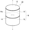
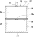
- FIG. 1 is a schematic perspective view showing an example of a soundproof structure (hereinafter referred to as a soundproof structure 10) according to the present invention.
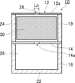
- FIG. 2 is an exploded view of the soundproof structure 10.
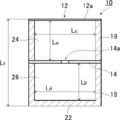
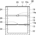
- FIG. 3 is a cross-sectional view taken along line II of the soundproof structure 10 illustrated in FIG.
- the soundproof structure 10 uses a membrane vibration and Helmholtz resonance to exhibit a sound absorbing function and selectively mute a sound having a specific frequency (frequency band).
- the soundproof structure 10 includes a film-like member 12, a plate-like member 14 having a through hole 14 a that is disposed to face one surface of the plate-like member 14, and a plate And a support 16 that supports the film-like member 14 and the film-like member 12.
- a back space 24 is formed between the plate member 14 and the film member 12, and a first space 26 is formed on the opposite side of the back space 24 with the plate member 14 interposed therebetween.
- the support body 16 is composed of a plurality of frames, and in the soundproof structure 10 shown in FIGS. 1 to 3, the support body 16 includes two inner frames 18 and an outer frame 19. Become.
- the outer frame body 19 is a cylindrical frame body having an opening 40 penetrating in the thickness direction.
- the membrane member 12 is disposed on one opening surface 41 of the outer frame body 19, and the plate member 14 is disposed on the other opening surface 42.
- the inner frame 18 is a bottomed cylindrical frame having a bottom wall 22.
- a plate-like member 14 is disposed on the opening surface 21 of the inner frame 18. That is, the plate-like member 14 is supported by being sandwiched between the outer frame body 19 and the inner frame body 18.
- the inner frame body 18 and the outer frame body 19 are made of a rigid body, and support the edge of the plate-like member 14 by being fixed. I support it as possible.
- the “rigid body” can be regarded as a substantially rigid body. Specifically, the rigidity is sufficiently larger than the rigidity of the film-like member 12 and is stationary without vibrating while the film-like member 12 is vibrating. On the other hand, it is overwhelmingly thick and has extremely high bending rigidity. If the hardness is sufficiently large with respect to the film member 12, the vibration of the rigid body can be substantially ignored with respect to the vibration of the film member 12 when sound is incident.
- the edge of the membrane member 12 is a fixed end and is not vibrated because it is fixed to the outer frame 19 that is a rigid body. Whether or not the edge portion of the film-like member 12 (that is, the outer frame body 19) does not vibrate (is stationary) can be confirmed by measurement using laser interference. Specifically, if the amount of displacement of the edge of the film-like member 12 is about 1/100 or less of the amplitude of the vibrating part (film part 12a) of the film-like member 12, it is regarded as a rigid body. The amount of displacement is inversely proportional to the product of Young's modulus (longitudinal elastic modulus) and the moment of inertia of the section.
- the cross-sectional second moment is proportional to the third power of the thickness and the first power of the width. Therefore, the displacement amount is proportional to 1 / (E ⁇ w ⁇ h 3 ) when Young's modulus E, thickness h, and width w are set. Therefore, in order to set the displacement amount to 1/100 or less, it is only necessary that (E ⁇ w ⁇ h 3 ) of the outer frame body 19 is 100 times or more that of the film member 12.
- the film-like member 12 is vibrated by applying salt or white fine particles to the film-like member 12, it is visually observed by observing that the above-mentioned fine particles are still standing at the edge of the film-like member 12. Can be confirmed.
- the inner frame 18 is a bottomed cylindrical frame as shown in FIG. 2, and an opening 20 formed of a circular cavity is provided at the center portion in the radial direction.
- One end surface (outer end portion) of the inner frame 18 in the thickness direction is an opening surface 21.
- An edge (outer edge) of the plate-like member 14 is fixed to the opening surface 21 of the inner frame 18.
- the inner frame 18 is provided with a bottom wall 22 that closes the surface of the opening 20 opposite to the opening surface 21 on which the film-like member 12 is disposed. That is, the opening 20 of the inner frame 18 has a bottom surface at a position opposite to the opening surface 21.
- FIG. 2 In the example shown in FIG.
- the bottom wall 22 is formed integrally with the inner frame body 18 is shown, but the present invention is not limited to this. Yes, it may be joined for integration.
- the bottom wall 22 may be comprised by the plate-shaped member, or may be comprised by thin members, such as a film.
- the outer frame body 19 corresponds to a cylindrical frame body, and is a cylindrical frame body as shown in FIG.
- the outer frame body 19 is formed with an opening 40 formed of a circular cavity that penetrates from one end of the outer frame body 19 to the other end in the thickness direction.
- the opening 40 of the outer frame 19 has the same diameter as the opening 20 of the inner frame 18.
- the edge of the plate-like member 14 is fixed to the opening surface 42 of the outer frame 19 on the inner frame 18 side.
- the edge (outer edge) of the film-like member 12 is fixed to the opening surface 41 located on the opposite side of the outer frame 19 from the inner frame 18.
- the membrane member 12 is supported by the outer frame 19 in a state in which the membrane portion 12a can vibrate.
- the membrane portion 12a is a membrane body portion of the membrane-like member 12 that faces the opening 40 inside the fixed outer edge and vibrates.
- the film-like member 12 is a circular thin film body whose outer shape is approximately the same as the opening surface 41 of the outer frame body 19.
- the edge (outer edge) of the film-like member 12 is fixed to the opening surface 41 of the outer frame body 19. Thereby, the film-like member 12 is supported by the outer frame 19 in a state in which the film portion 12a can vibrate.
- the film-like member 12 is disposed at the outer end in the thickness direction of the soundproof structure 10 and is exposed to the sound source. That is, the soundproof structure 10 is arranged in the order of the film-like member 12 and the plate-like member 14 with respect to the sound source to be sound-absorbed.
- the plate-like member 14 is a circular plate-like member having an outer diameter that is substantially the same as the opening surface 21 of the inner frame 18.
- the edge of the plate member 14 (outer edge) is fixed by being sandwiched between the opening surface 21 of the inner frame 18 and the opening surface 42 of the outer frame 19. Further, a through hole 14 a is formed in a substantially central portion of the plate-like member 14.
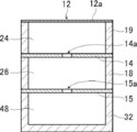
- the soundproof structure 10 is configured by stacking the inner frame 18, the plate-like member 14, the outer frame 19, and the film-like member 12 in order from the inner side in the thickness direction. ing. As shown in FIG. 3, the film-like member 12 and the plate-like member 14 face each other via the outer frame 19 in the thickness direction.
- a back space 24 is formed between the plate-like member 14 and the film-like member 12 in the soundproof structure 10.
- the back space 24 is sandwiched between the plate-like member 14 and the film-like member 12 in the thickness direction, and the periphery thereof is surrounded by the outer frame body 19.
- the plate-like member 14 and the film-like member 12 sandwiching the back space 24 are opposed to each other with the outer frame body 19 interposed therebetween.
- a first space 26 is formed inside the soundproof structure 10 on the side opposite to the back space 24 (that is, inside) with the plate-like member 14 interposed therebetween.
- the first space 26 is a space surrounded by the plate-like member 14 fixed to the opening surface 21 of the inner frame 18 and the inner frame 18.
- the film-shaped member 12 is arrange
- the film-like member 12 closes one end face (opening face 41) of the opening 40 of the outer frame 19.
- a plate-like member 14 is disposed between the outer frame body 19 and the inner frame body 18, and this plate-like member 14 closes the other end surface (opening surface 42) of the opening 20 of the outer frame body 19. It is out. That is, the back space 24 and the first space 26 are communicated with each other through the through hole 14 a formed in the plate-like member 14.
- each sound absorbing portion absorbs a sound having a specific frequency. Specifically, it has a first sound absorbing portion that absorbs sound when the membrane member vibrates, and a second sound absorbing portion that resonates by Helmholtz resonance.
- a soundproof structure 10 of the present invention there are a plurality of frequency bands in which sound can be absorbed. Among them, sound absorption is caused by the interaction between the film-like member and the plate-like member. A sound absorption frequency band in which the resonance is in the same direction and a sound absorption frequency band in which the membrane vibration and the Helmholtz resonance are in the opposite directions are included.
- the first sound absorbing part is a sound absorbing part constituted by the film-like member 12, the outer frame body 19, the plate-like member 14, and the back space 24.
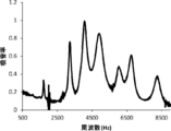
- the first sound absorbing portion absorbs sound at a relatively high frequency (for example, 3 kHz to 5 kHz) by the membrane vibration of the film-like member 12. That is, the frequency band of sound absorption mainly contributed by the first sound absorbing portion corresponds to the frequency band of sound absorption mainly due to the membrane vibration of the film-like member 12 adjacent to the back space 24.
- the second sound absorbing part is a sound absorbing part constituted by the plate-like member 14, the inner frame 18 and the first space 26.
- the second sound absorbing portion absorbs sound by generating Helmholtz resonance by the through hole 14 a formed in the plate-like member 14 and the first space 26. That is, the frequency band of sound absorption mainly contributed by the second sound absorbing portion corresponds to the frequency band of sound absorption mainly caused by Helmholtz resonance generated by the through hole 14a formed in the plate-like member 14 and the first space 26. .
- the soundproof structure 10 has a mode in which the membrane vibration of the first sound absorbing portion and the Helmholtz resonance of the second sound absorbing portion act simultaneously.
- the soundproof structure 10 has a mode in which the membrane vibration and the Helmholtz resonance are in the same direction as a mode in which the membrane vibration and the Helmholtz resonance interact, and a mode in which the membrane vibration and the Helmholtz resonance are in the opposite directions.
- the sound absorption by the membrane vibration alone of the membrane member 12 of the first sound absorbing portion and the frequency band higher than the sound absorption by the Helmholtz resonance alone of the second sound absorbing portion for example, , 8 kHz to 9 kHz.
- each sound absorbing part will be described in detail.
- the first sound absorbing unit selectively absorbs sound in a predetermined frequency band by the membrane vibration of the film-like member 12.
- the frequency of membrane vibration is determined by the thickness, hardness, size, fixing method, and the like of the membrane member 12.
- the membrane vibration has a fundamental vibration mode and a higher-order vibration mode.
- the frequency of at least one higher-order vibration mode existing at 1 kHz or more of the membrane vibration of the membrane member 12 adjacent to the back space 24 is obtained. It is preferable that the sound absorption coefficient at is higher than the sound absorption coefficient at the frequency of the fundamental vibration mode. Details of how this configuration has been achieved are described below.
- Various electronic devices such as copiers have a sound source such as an electronic circuit and an electric motor that are sources of noise, and each of these sound sources generates a loud sound with a specific frequency.
- a porous sound absorber generally used as a silencer means that the sound is silenced at a wide frequency, so that the noise of the frequency inherent to the sound source cannot be sufficiently silenced and becomes relatively easy to hear than other frequencies. was there.
- a silencer using a membrane vibration is known as a means for greatly muting a specific frequency sound.
- the frequency of noise generated by the electronic circuit and the electric motor described above has become higher.
- a silencing means using membrane vibration it is conceivable to increase the natural frequency of the membrane vibration by adjusting the hardness and size of the membrane member.
- the film-like member is too hard (or thick), the sound is likely to be reflected by the film. Therefore, as shown in FIG. 4, the higher the frequency of the fundamental vibration mode, the smaller the sound absorption (sound absorption rate) due to the membrane vibration.
- the membrane member needs to be hardened for higher frequency. Hardening the film-like member leads to an increase in reflection on the film surface. It is considered that the absorption is reduced because most of the sound is reflected from the surface of the film instead of being absorbed by the resonance vibration because a harder film-like member is required for resonance as the high-frequency sound is resonated. Therefore, it has been clarified that it is difficult to absorb a large amount of sound at a high frequency with a silencer using a membrane vibration using a fundamental vibration mode based on a conventional design theory. This characteristic is unsuitable for use in silencing high frequency specific sounds.
- the graph shown in FIG. 4 is a result of simulation using the finite element method calculation software COMSOLCOMver.5.3 (COMSOL Inc.).
- the calculation model was a two-dimensional axisymmetric structure calculation model, the frame was cylindrical, the diameter of the opening was 10 mm, and the thickness of the back space was 20 mm.
- the film-like member was 250 ⁇ m in thickness, and the Young's modulus, which is a parameter representing the hardness of the film-like member, was variously changed in the range of 0.2 GPa to 10 GPa.
- the evaluation was performed with the normal incident sound absorption coefficient arrangement, and the maximum value of the sound absorption coefficient and the frequency at that time were calculated.
- the sound absorption coefficient at the frequency of at least one higher-order vibration mode existing at 1 kHz or more of the membrane vibration of the membrane member 12 is set.
- the structure has a higher sound absorption rate than the fundamental vibration mode frequency.
- the first sound absorbing portion is made to increase the sound absorption coefficient at the higher order natural frequency such as the second order and third order natural frequencies, and the membrane vibration of the higher order vibration mode. Since it is not necessary to harden (or thicken) the film-like member, the sound can be suppressed from being reflected by the film surface, and a high sound absorption effect can be obtained even at a high frequency. Can do.
- the 1st sound absorption part which is a single layer film structure absorbs sound using a membrane vibration, it can mute suitably the sound of a specific frequency with a small light weight.
- the present inventors estimated the mechanism by which the higher-order vibration mode is excited as follows. There are frequency bands of fundamental vibration mode and higher-order vibration mode determined by the conditions (thickness, hardness, size, fixing method, etc.) of the film-like member. Which mode is strongly excited to contribute to sound absorption? Is determined by the distance of the back space. This will be described below.
- the resonance of the sound absorbing structure using the film-like member is considered separately, there are a part involving the film-like member and a part involving the back space. Therefore, sound absorption occurs due to these interactions.
- a resonance phenomenon occurs when this total acoustic impedance matches the acoustic impedance of the medium fluid (such as air).
- the acoustic impedance Zm of the membrane member is determined by the specification of the membrane member.
- the component (mass law) according to the equation of motion by the mass of the membrane member and the membrane member are fixed. Therefore, resonance occurs when components (stiffness law) governed by tension such as a spring coincide with each other.
- the higher-order vibration mode is resonance due to the shape of the membrane vibration that is more complicated than the fundamental vibration.
- the band for the fundamental vibration mode becomes wide.
- the sound absorption is reduced because the film-like member is hard and easily reflected.
- the film member has a condition where the higher vibration mode is likely to occur, such as by reducing the thickness of the film member, the frequency bandwidth in which the fundamental vibration mode is generated becomes smaller, and the higher vibration mode exists in the high frequency region. It becomes.
- the acoustic impedance Zb in the back space is different from the impedance in the open space because the flow of air-propagating sound is restricted by the closed space or the through-hole portion, and the back space becomes harder as the thickness of the back space becomes smaller.
- the resonance of the lower frequency sound becomes smaller because the back space is too small for the wavelength. That is, the frequency of the sound that can resonate is determined by the change in the back distance.
- the frequency of the fundamental vibration and the higher-order vibration in another band are determined depending on the specifications of the membrane member.
- the simulation was performed using the acoustic module of the finite element method calculation software COMSOL ver.5.3 (COMSOL Inc.).
- the calculation model of the soundproof structure 10 will be described.
- the frame body has a cylindrical shape, the opening has a diameter of 20 mm, the film member has a thickness of 50 ⁇ m, and the Young's modulus of the film member has a Young's modulus of a PET (polyethylene terephthalate) film. It was set to 4.5 GPa.
- the calculation model was a two-dimensional axisymmetric structure calculation model.
- FIG. 5 is a graph plotting the frequency at which the sound absorption rate is maximum in each calculation model (hereinafter referred to as peak frequency) and the sound absorption rate at the peak frequency.
- peak frequency the frequency at which the sound absorption rate is maximum in each calculation model
- FIG. 6 shows a graph in which the relationship between the peak frequency of each calculation model and the thickness of the back space is plotted as a logarithm, and a line is drawn for each order of the vibration mode.
- 7 and 8 are graphs showing the relationship between the frequency and the sound absorption coefficient in each calculation model when the thickness of the back space is 7 mm, 5 mm, 3 mm, 2 mm, 1 mm, and 0.5 mm.
- the peak frequency of the sound absorption rate is increased by reducing the thickness of the back space.
- the peak frequency does not increase continuously on the logarithmic axis, but a plurality of discontinuous changes occur on the logarithmic axis. .
- This characteristic indicates that the vibration mode in which the sound absorption coefficient is maximum is shifted from the fundamental vibration mode to a higher-order vibration mode or a vibration mode having a higher order of the higher-order vibration mode. That is, it was found that the high-order vibration mode is easily excited by the thin film-like member, and that the sound absorption effect by the high-order vibration mode rather than the fundamental vibration mode appears greatly by reducing the thickness of the back space.
- a large sound absorption coefficient in the high frequency range is not caused by the fundamental vibration mode but caused by resonance by the higher order vibration mode. From the line drawn for each order of the vibration mode shown in FIG. 6, the thinner the back space, the higher the frequency in the vibration mode, that is, the frequency at which the sound absorption coefficient is the highest. I understand.
- the film thickness of the film-like member is as thin as 50 ⁇ m.
- the higher-order vibration mode has a complicated vibration pattern on the film as compared with the fundamental vibration mode. That is, it has a plurality of antinodes on the membrane. Therefore, compared with the fundamental vibration mode, bending with a smaller plane size is necessary, and there are many vibration modes that require bending near the membrane fixing portion (the edge of the membrane member). It is important to reduce the film thickness in order to use the higher-order vibration mode because the smaller the film thickness is, the easier it is to bend.
- a structure with a thin film thickness is a system in which the hardness of the film-like member is small. In such a system, reflection with respect to high-frequency sound is small, and it is considered that a large sound absorption rate can be obtained even on the high-frequency side.
- the sound absorption coefficient has a maximum value (peak) at a plurality of frequencies.
- the frequency at which the sound absorption coefficient is a maximum value is the frequency of a certain vibration mode.
- the lowest frequency of about 1500 Hz is the frequency of the fundamental vibration mode. That is, in any calculation model, the frequency of the fundamental vibration mode is about 1500 Hz.
- the frequency which becomes the maximum value existing in the frequency higher than 1500 Hz that is the fundamental vibration mode is the frequency of the higher-order vibration mode.
- the sound absorption rate at the frequency of the higher-order vibration mode is higher than the sound absorption rate at the frequency of the fundamental vibration mode.
- the fundamental vibration mode is a vibration mode that appears on the lowest frequency side
- the higher-order vibration mode is a vibration mode other than the fundamental vibration mode.
- Whether the vibration mode is the fundamental vibration mode or the higher-order vibration mode can be determined from the state of the film member 12.
- the center of gravity of the film-like member 12 has the largest amplitude, and the amplitude in the vicinity of the peripheral fixed end (edge) is small.
- the film member 12 has a speed in the same direction in all the regions.
- the membrane vibration in the higher-order vibration mode the film-like member 12 has a portion having a speed in the reverse direction depending on the position.
- the edge of the fixed film member 12 becomes a vibration node, and no node exists on the film portion 12a.
- the high-order vibration mode in addition to the edge portion (fixed end portion) according to the above definition, there is a portion serving as a vibration node on the membrane portion 12a. it can.
- vibration mode analysis vibration mode can be directly observed by measuring membrane vibration using laser interference.
- the position of the node can be visualized by oscillating the salt or white fine particles on the membrane surface, and this method can be used for direct observation. This visualization of the vibration mode is known as a Cladoni figure.
- the frequency in each vibration mode can also be obtained analytically.
- the frequency in each vibration mode can be obtained for an arbitrary film shape.
- the sound absorption coefficient can be obtained by sound absorption coefficient evaluation using an acoustic tube.
- a measurement system for normal incidence sound absorption coefficient according to JIS A 1405-2 is prepared and evaluated.
- WinZacMTX manufactured by Nippon Acoustic Engineering can be used.
- the internal diameter of the acoustic tube is 20 mm, and the soundproof structure to be measured is arranged at the end of the acoustic tube with the outer end surface facing the front side (acoustic incident side), and the reflectance is measured.
- the sound absorption coefficient is evaluated by obtaining the reflectance. It is possible to measure up to high frequency as the diameter of the acoustic tube is reduced. Since it is necessary to measure the sound absorption characteristics up to high frequencies this time, an acoustic tube having a diameter of 20 mm is selected.
- the thickness of the back space 24 the film shape
- the size, thickness, hardness, density, etc. of the member 12 may be adjusted.
- the thickness of the back space 24 (La in FIG. 3) is preferably 10 mm or less, more preferably 5 mm or less, further preferably 2 mm or less, and particularly preferably 1 mm or less. If the thickness of the back space 24 is not uniform, the average value may be in the above range.
- the thickness of the film-like member 12 is preferably less than 100 ⁇ m, more preferably 70 ⁇ m or less, and further preferably 50 ⁇ m or less. In addition, when the thickness of the film-shaped member 12 is not uniform, an average value should just be the said range.
- the Young's modulus of the membrane member 12 is preferably 1 MPa to 100 GPa, more preferably 10 MPa to 50 GPa, and most preferably 100 MPa to 30 GPa.
- the density of the film member 12, it is preferably, more preferably from 100kg / m 3 ⁇ 20000kg / m 3, 500kg / m 3 ⁇ 10000kg / m 3 is 10kg / m 3 ⁇ 30000kg / m 3 Most preferred.
- the shape of the membrane portion 12a of the membrane member 12 (the shape of the membrane vibrating region), in other words, the shape of the opening cross section of the frame (the inner frame 18 and the outer frame 19) is not particularly limited.
- Other quadrilaterals such as squares, rectangles, rhombuses or parallelograms, polygons including regular triangles such as regular triangles, isosceles triangles, right triangles, regular pentagons, regular hexagons, circles, ellipses It may be a shape or the like, or may be indefinite.
- the size of the membrane portion 12a of the membrane-like member 12 (the size of the membrane vibrating region), in other words, the size of the opening cross section of the frame is preferably 1 mm to 100 mm in terms of the equivalent circle diameter (Lc in FIG. 3). 3 mm to 70 mm is more preferable, and 5 mm to 50 mm is further preferable.
- the sound absorption rate is higher than the sound absorption rate at the frequency of the fundamental vibration mode, and the sound absorption rate at the frequency of at least one higher-order vibration mode is preferably 20% or more, more preferably 30% or more, It is more preferably 50% or more, particularly preferably 70% or more, and most preferably 90% or more.
- a higher-order vibration mode having a higher sound absorption rate than the sound absorption rate at the frequency of the fundamental vibration mode is also simply referred to as “high-order vibration mode”, and the frequency is also simply referred to as “high-order vibration mode frequency”. .
- the sound absorption rate in the frequency of two or more higher-order vibration modes is 20% or more, respectively.
- the sound absorption rate is 20% or more at a plurality of higher-order vibration mode frequencies, sound can be absorbed at a plurality of frequencies.
- the high-order vibration mode in which the sound absorption coefficient is 20% or more is continuously present. That is, for example, it is preferable that the sound absorption coefficient at the frequency of the secondary vibration mode and the sound absorption coefficient at the frequency of the tertiary vibration mode are each 20% or more. Furthermore, when there is a continuous high-order vibration mode in which the sound absorption coefficient is 20% or more, the sound absorption coefficient is preferably 20% or more over the entire band between the frequencies of these high-order vibration modes. Thereby, a sound absorption effect can be obtained in a wide band.
- the second sound absorbing part is a sound absorbing part constituted by the plate-like member 14, the inner frame 18 and the first space 26.
- the second sound absorbing portion absorbs sound by generating Helmholtz resonance by the through hole 14 a formed in the plate-like member 14 and the first space 26.
- the fundamental frequency of Helmholtz resonance is determined by the opening area of the through hole, the length of the through hole, and the volume of the first space.
- the structure basically absorbs sound in a band centered on one frequency by the frequency of the fundamental resonance mode, and no higher-order resonance mode is generated.
- the interaction between the first sound absorbing portion and the second sound absorbing portion is such that both the membrane vibration of the film-like member 12 in the first sound absorbing portion and the air vibration due to Helmholtz resonance in the second sound absorbing portion are sandwiched across the back space 24. Interaction is obtained by vibration.
- the mode that absorbs sound by giving the phase change in the same direction between the membrane vibration and the Helmholtz resonance that is, the vibration direction of the membrane and the phase of the sound passing through the Helmholtz part are the same direction
- the membrane vibration and the Helmholtz resonance There is a mode in which sound is absorbed by applying a phase change in the reverse direction (that is, the vibration direction of the film and the phase of the sound passing through the Helmholtz-bi portion are reverse).
- the mode that absorbs sound when the membrane vibration and Helmholtz resonance give a phase change in the same direction absorbs sound at the low frequency side
- the mode that absorbs sound when the membrane vibration and Helmholtz resonance gives a phase change in the opposite direction Absorb sound.
- the mode of absorbing sound on the high-frequency side by applying phase changes in opposite directions between the membrane vibration and the Helmholtz resonance is the sound absorption by the membrane vibration alone of the membrane member 12 of the first sound absorbing portion and the Helmholtz resonance alone of the second sound absorbing portion. Sound is absorbed in a frequency band higher than the sound absorption (for example, 8 kHz to 9 kHz).
- FIGS. 9 and 10 show a soundproof structure having a configuration in which the fundamental frequency of membrane vibration in the first sound absorbing unit alone is 1.7 kHz and the fundamental frequency of Helmholtz resonance in the second sound absorbing unit alone is 4.5 kHz. It is the figure which showed distribution of the sound pressure in a soundproof structure when the sound of sound pressure 1Pa injects from the upper side in a figure with frequency 2.7kHz and 7.4kHz, respectively. As is well known, the sound pressure is the fluctuation of the pressure due to sound from the atmospheric pressure.
- the sound pressure increases due to an increase in the horizontal sound component.
- the cancellation of the phase relationship in the reverse direction results in vibration equivalent to that the thickness of the back space 24 is reduced, and the membrane member 12 vibrates in a higher order vibration mode. Absorbs the high frequency side.
- FIG. 9 and FIG. 10 show the results of simulation using the acoustic module of the finite element method calculation software COMSOL ver.5.3 (COMSOL Inc.). Specifically, a soundproof structure in which the circular film-shaped member 12, the outer frame body 19, the plate-shaped member 14, and the inner frame body 18 are stacked in this order is modeled, and a coupled analysis calculation of sound and structure is performed. It was. At this time, the structural calculation was performed for the membrane member 12, and the simulation was performed by calculating the air propagation of sound for the back space 24 and the first space 26.
- the calculation model was a two-dimensional axisymmetric structure calculation model.
- FIG. 9 and FIG. 10 show the axisymmetric diagrams connected to the left and right.
- thermoviscous acoustic calculation was performed in the through hole where Helmholtz resonance occurred, and the calculation including the frictional heat absorption due to viscous friction was performed accurately. These physical modes were coupled and calculated.
- the calculation model of the soundproof structure 10 will be described.
- the inner frame 18 and the outer frame 19 are cylindrical, and the diameters of the opening 20 and the opening 40 are 20 mm.
- the film-like member 12 had a thickness of 50 ⁇ m, and the Young's modulus was 4.5 GPa, which is the Young's modulus of a PET (polyethylene terephthalate) film.
- the plate-like member 14 had a thickness of 2 mm, and a through hole 14a having a diameter of 6 mm was formed at the center.
- the thickness of each of the back space 24 and the first space 26 was 2 mm.
- the evaluation was performed with the normal incident sound absorption coefficient arrangement, and the maximum value of the sound absorption coefficient and the frequency at that time were calculated.
- the first sound absorbing portion and the second sound absorbing portion are overlapped, and the membrane vibration of the membrane member 12 and the air vibration due to Helmholtz resonance are in opposite phases.
- the soundproof structure 10 of the present invention has a low frequency side sound absorption region that absorbs sound when the membrane vibration and Helmholtz resonance give the same phase change, and the membrane vibration and Helmholtz resonance give the phase change in the opposite direction. Since sound can be absorbed simultaneously in the high frequency side sound absorption region that absorbs sound, it is possible to absorb sound over a wider band.
- the effectiveness of the soundproof structure 10 of the present invention will be described in detail with reference to FIGS.
- FIG. 11 is a reference example 1, which is a soundproof structure having only a first sound absorbing portion (that is, a soundproof structure having only a single-layer film structure without the inner frame 18 and the first space 26, 6 is a graph showing the relationship between the frequency and the sound absorption coefficient when the plate-like member 14 is a rigid body in which no through-hole is formed.
- FIG. 12 is a reference example 2, which is a soundproof structure including only the second sound absorbing portion (ie, a Helmholtz resonator alone without the membrane member 12, the outer frame 19, and the back space 24, hereinafter referred to as “Helmholtz”. It is also a graph showing the relationship between the frequency and the sound absorption coefficient in a “resonance unit soundproof structure”.
- FIGS. 13 to 15 are graphs showing the relationship between the frequency and the sound absorption coefficient in Examples 1 to 3 of the soundproof structure 10 according to an example of the present invention, respectively.
- the graphs shown in FIGS. 11 to 15 are in accordance with the acoustic tube measurement method described above, with a soundproof structure at the end of the soundtube having a plate-like member (a membrane-like member for a soundproof structure with a single membrane vibration) on the front side. It arrange
- the outer frame 19 is a cylindrical acrylic plate, the outer frame 19 has an outer diameter of 40 mm, the opening 40 has a diameter of 20 mm, and the membrane member 12 has a thickness.
- a 50 ⁇ m PET (polyethylene terephthalate) film is used.
- the soundproof structure of the membrane vibration alone has a structure in which a back plate made of a rigid body (aluminum plate having a thickness of 100 mm) is pressed against the bottom surface of the back space 24. That is, in the soundproof structure with a single membrane vibration, the back space 24 is a closed space. Moreover, the thickness of the back space 24 is 2 mm.
- the outer frame body 19 was produced by processing an acrylic plate (manufactured by Hikari Co., Ltd.) having a thickness of 2 mm using a laser cutter. Further, the outer frame 19 and the film-like member 12 were bonded to each other with a double-sided tape (the power of ASKUL's site) with the outer edge of the donut-shaped acrylic plate and the outer edge of the PET film aligned. . Therefore, the range in which the membrane member can vibrate is 20 mm in diameter, and the vibration is fixed at the end.
- the normal incident sound absorption coefficient was measured in the same manner as described below. Using a laser cutter, make one circular plate with an outer diameter of 40 mm, and double-sided tape (ASKUL) with the outer diameter of the outer edge of the doughnut-shaped plate and the outer edge of the circular plate matched. A frame was prepared by bonding a circular plate to the surface of the donut-shaped plate opposite to the membrane member using the power of the manufacturing site. Even in the above configuration, the same measurement result as that obtained by pressing a rigid body made of an aluminum plate having a thickness of 100 mm on the back surface of the soundproof structure was obtained.
- ASKUL double-sided tape
- the soundproof structure of the Helmholtz resonance unit is an acrylic plate in which the inner frame 18 is a cylindrical acrylic plate, the inner frame 18 has an outer diameter of 40 mm, the opening 20 has a diameter of 20 mm, and the plate member 14 has a thickness of 2 mm. It is said. Further, a through hole 14 a having a diameter of 6 mm was provided at the center position of the plate-like member 14.
- the soundproof structure of the membrane vibration alone has a structure in which a back plate made of a rigid body (a 100 mm thick aluminum plate) is pressed against the bottom surface of the back space 24. The thickness of the first space 26 is 2 mm.
- Reference Example 3 a case where the diameter of the through hole 14a formed in the plate-like member 14 is 4 mm is referred to as Reference Example 3, and a case where the diameter of the through hole 14a is 8 mm is referred to as Reference Example 4.
- the soundproof structure 10 is provided with an inner frame 18, a plate-like member 14, an outer frame 19 and a film-like member 12 in order from the inside.
- the inner frame 18 and the outer frame 19 are made of a cylindrical acrylic plate, each having an outer diameter of 40 mm and an opening having a diameter of 20 mm.
- the film member 12 is a PET (polyethylene terephthalate) film having a thickness of 50 ⁇ m.
- the plate member 14 is an acrylic plate having a thickness of 2 mm, and a through hole 14 a is provided at the center position of the plate member 14.
- the soundproof structure 10 according to an example of the present invention is provided with a bottom wall 22 at the bottom of the opening 20 of the inner frame 18.
- a space (hereinafter, also referred to as an internal space of the soundproof structure) that combines the back space 24 and the first space 26 is a closed space.
- the thickness of each of the back space 24 and the 1st space 26 is 2 mm.
- FIG. 13 shows the frequency and sound absorption coefficient when the diameter of the through-hole 14a formed in the plate-like member 14 is 6 mm, that is, when the configuration of Reference Example 1 and Reference Example 2 is combined (referred to as Example 1). It is the graph which measured the relationship.
- FIG. 13 shows the frequency and sound absorption coefficient when the diameter of the through-hole 14a formed in the plate-like member 14 is 6 mm, that is, when the configuration of Reference Example 1 and Reference Example 2 is combined (referred to as Example 1). It is the graph which measured the relationship.
- FIG. 14 shows the frequency and sound absorption coefficient when the diameter of the through-hole 14a formed in the plate-like member 14 is 4 mm, that is, when the configuration of Reference Example 1 and Reference Example 3 is combined (referred to as Example 2).
- FIG. 15 is a graph showing a case where the diameter of the through hole 14a formed in the plate-like member 14 is 8 mm, that is, a configuration in which Reference Example 1 and Reference Example 4 are combined (implemented). It is the graph which measured the relationship between the frequency of (example 3) and a sound absorption rate.
- FIG. 11 that the soundproof structure of the membrane vibration alone has a structure that absorbs sound at a plurality of frequencies by vibrations of the fundamental vibration mode and the higher-order vibration mode of the membrane member 12 adjacent to the back space 24.
- FIG. 11 shows that the frequency of the fundamental vibration mode is 1.7 kHz.
- a plurality of high sound absorption peaks appear in a band of 3 kHz to 5 kHz, and each peak shows a high sound absorption coefficient.
- the sound absorption rate is less than 50%.
- a high sound absorption coefficient can be obtained by the membrane vibration in the fundamental vibration mode or the higher order vibration mode of the membrane in a specific frequency band. In the vibration mode, the sound absorption rate tends to be low.
- the soundproof structure of the single Helmholtz resonance absorbs sound in a band centered on one frequency by the frequency of the fundamental vibration mode of the Helmholtz resonance.
- the frequency of the fundamental vibration mode is 4.5 kHz. From FIG. 12, it can be seen that the peak of the sound absorption coefficient is gentle compared to the case of the membrane vibration alone. It can also be seen that no peaks other than the fundamental vibration mode appear.
- each of the plurality of sound absorption peaks appearing in the band of 2.0 kHz to 4.5 kHz exhibits a high sound absorption rate.
- the sound absorption peak that appears in the vicinity of 7.0 kHz to 8.5 kHz shows a sound absorption rate of 60% or more.
- Table 2 also shows the value of the ratio f h1 / f m1 between the fundamental frequency f m1 of the membrane vibration and the fundamental frequency f h1 of the Helmholtz resonance.
- the ratio f h1 / f m1 between the fundamental frequency f m1 of the membrane vibration and the fundamental frequency f h1 of the Helmholtz resonance is larger than 1.
- the sound absorption characteristics of Examples 1 to 3 having a configuration in which a membrane vibration resonator and a Helmholtz resonator are stacked have a high-frequency peak on the side larger than the fundamental frequency of either the Helmholtz resonator alone or the membrane vibration alone. The frequency appears and has a large sound absorption coefficient.
- the low frequency side sound absorption region that absorbs sound when the membrane vibration and Helmholtz resonance change in the same direction is, for example, 2.0 kHz
- the high-frequency side sound absorption region that absorbs sound when the membrane vibration and Helmholtz resonance give a phase change in the opposite direction is, for example, 7.0 kHz to 8.5 kHz. Therefore, the soundproof structure 10 according to an example of the present invention can simultaneously absorb a plurality of relatively high frequency sounds such as motor sounds and inverter sounds.
- the frequency band that absorbs sound when the membrane vibration and Helmholtz resonance change in the same direction is referred to as the “low frequency side sound absorption frequency band” or the “low frequency side sound absorption region”.
- the frequency band in which sound is absorbed when Helmholtz resonance gives a phase change in the opposite direction is referred to as a “high frequency side sound absorption frequency band” or a “high frequency side sound absorption region”.
- the sound absorption peak that appears in the sound absorption frequency band on the low frequency side is referred to as “the sound absorption peak on the low frequency side”
- the sound absorption peak that appears in the sound absorption frequency band on the high frequency side is referred to as “the sound absorption peak on the high frequency side”.
- the frequency of the sound absorption peak on the low frequency side is the thickness of the membrane member 12, the thickness of the back space 24, the thickness of the first space 26, the thickness of the plate member 14, and the plate shape. It can be changed by adjusting the size or the like of the through hole 14a formed in the member 14.
- the frequency of the sound absorption peak on the high frequency side is the thickness of the membrane member 12, the thickness of the back space 24, the thickness of the first space 26, the thickness of the plate member 14, and the through hole 14a formed in the plate member 14. It can be changed by adjusting the size etc.
- the frequencies of the sound absorption peaks on the low frequency side and the high frequency side can be independently controlled. That is, since the pressure distribution varies depending on the sound absorption region, independent control can be performed. Specifically, in the low frequency side sound absorption region, the pressure increases to the low wall side, so the influence of the thickness and volume of the first space is large, while in the high frequency side sound absorption region, the pressure in the back space increases, so And the effect of volume is large. Therefore, for example, if the thicknesses of the first space and the back space are changed, the low frequency region and the high frequency region can be changed independently. As a result, the frequency of each sound absorption peak can be appropriately controlled in accordance with the frequency of the noise to be absorbed, and as a result, sound absorption is efficiently performed.
- the ability to independently change the frequency of the sound absorption peak on the low frequency side and the high frequency side is also effective for simple noise caused by vibration of a metal rod or the like. That is, in the conventional sound absorbing device using membrane vibration, the vibration mode of the membrane (resonance based on two-dimensional vibration) and the vibration mode of a metal rod or the like (resonance based on one-dimensional vibration) have frequency intervals for respective orders. Because of the difference, it is difficult to match the resonance peak of the membrane vibration at a plurality of frequencies with respect to simple noise derived from a metal rod, and it is difficult to suitably absorb such simple noise. The same was true for motor, inverter, and fan noises, where peak noise appears at integer multiples.
- the soundproof structure 10 of the present invention can appropriately change the frequency of the sound absorption peak in each sound absorption frequency band as described above. By setting a peak frequency suitable for absorbing simple noise due to vibration, simple noise can be appropriately absorbed.
- the soundproof structure of the present invention has a configuration in which a plate-like member having a through-hole and a film-like member are arranged at a predetermined distance from each other, the soundproofing structure can be made small, light, and thin, and the installation space for the silencer can be reduced. It can be suitably used for limited electronic devices.
- the fundamental frequency of membrane vibration when the plate-like member is a rigid body in which no through-hole is formed in the first sound-absorbing part is fm1
- the configuration satisfies f m1 ⁇ f h1 .
- the outer frame was cylindrical, the diameter of the opening was 20 mm, and the thickness of the first space was 2 mm.
- the plate member 14 had a thickness of 2 mm, and a through hole 14a having a diameter of 6 mm was provided at the center position.
- coupled calculation of sound and structure was performed, structural mechanics calculation was performed on the membrane member, and the back space was numerically calculated by calculating sound air propagation.
- the evaluation was performed with a normal incident sound absorption coefficient arrangement, and the relationship between the frequency and the sound absorption coefficient was calculated.
- the inside of the aperture hole where Helmholtz resonance is generated is accurately calculated including frictional heat absorption due to viscous friction by performing thermoviscous acoustic calculation.
- FIG. 16 shows the result of the simulation (relationship between the calculated frequency and the sound absorption coefficient).
- the simulation result is indicated by a solid line
- the actual measurement result is indicated by a dotted line as contrast information.
- the actual measurement result has a larger number of sound absorption peaks than the simulation result, and the degree of change in the sound absorption rate at each peak is large, but the overall trend is the difference between the actual measurement result and the simulation result.
- FIG. 17 is a graph showing the relationship between the frequency and the sound absorption coefficient when the through-hole diameters are 8 mm, 10 mm, and 12 mm.
- FIG. 18 is a graph showing the relationship between the frequency and the sound absorption coefficient when the through hole diameter is 1 mm, 2 mm, and 3 mm.
- the calculation is performed by simulation of the frequency and the sound absorption coefficient at each through-hole diameter from 1 mm to 19 mm as described above. From the simulation result, the maximum sound absorption coefficient in the low frequency side sound absorption region (hereinafter referred to as the low frequency side maximum sound absorption coefficient). And the frequency at which the sound absorption coefficient is maximum (hereinafter also referred to as the maximum sound absorption frequency on the low frequency side), the sound absorption coefficient at which the maximum is achieved in the high frequency side sound absorption region (hereinafter also referred to as the maximum sound absorption coefficient on the high frequency side), and the sound absorption coefficient are maximum. (Hereinafter also referred to as the high frequency side maximum sound absorption frequency). The results are shown in FIG. 19 and FIG.
- Table 3 shows the through-hole diameter, the low frequency side maximum sound absorption rate, the low frequency side maximum sound absorption frequency, the high frequency side maximum sound absorption rate, the high frequency side maximum sound absorption frequency, the Helmholtz simple fundamental frequency f h1 , and the membrane vibration in each simulation result.
- a table summarizing a single fundamental frequency f m1 and a frequency ratio f h1 / f m1 is shown.
- FIG. 21 shows the relationship between the sound absorption frequency and the high frequency side maximum sound absorption frequency of the Helmholtz resonance alone and the through-hole diameter.
- the low frequency side sound absorption region was a frequency region of 4 kHz or less, and the high frequency side sound absorption region was a frequency region of 4.8 kHz or more.
- the high frequency side sound absorption region extends to 12 kHz or more.
- the low frequency side sound absorption region hardly changes. From the above results, it can be seen that the low frequency side sound absorption region and the high frequency side sound absorption region can be controlled independently.
- the frequency change of the sound absorption region on the low frequency side is small when the through-hole diameter is about 5 mm or more.
- the sound absorption region on the high frequency side shifts to a high frequency as the through hole diameter increases.
- the plate-like member 14 is a rigid body having no through-holes 14a
- the fundamental frequency of membrane vibration of the membrane-like member 12 is 1.5 kHz. Therefore, only when the through-hole diameter is 1 mm, the fundamental frequency f h1 of Helmholtz resonance is lower than the fundamental frequency f m1 of membrane vibration.
- the maximum frequency is shifted to a higher frequency side than the fundamental frequency of the Helmholtz resonance alone by adopting a configuration in which the membrane-like member capable of vibrating membranes is arranged on the upper part of the Helmholtz resonator. .
- the fundamental frequency of the membrane vibration in the case of a rigid body is not formed a plate-like member through holes and f m1, Helmholtz second sound absorbing unit
- the fundamental frequency of the resonance and f h1 by satisfying f m1 ⁇ f h1, it is possible to obtain a sound absorbing effect at higher frequencies by the interaction of the membrane vibration and Helmholtz resonance of the film member 12, also, a plurality The sound absorption effect can be obtained in the frequency band.
- Each fundamental frequency may be appropriately selected according to the target noise.
- the frequency ratio f h1 / f m1 is 1.3 ⁇ f h1 / f. m1 ⁇ 12 is preferably satisfied, 1.5 ⁇ f h1 / f m1 ⁇ 8 is more preferable, and 2 ⁇ f h1 / f m1 ⁇ 5 is further more preferable. If the fundamental frequency ratio is too large, the sound absorption coefficient on the high frequency side tends to be small.
- the fundamental frequency of the Helmholtz resonance of the second sound absorbing portion may be adjusted by adjusting the size of the through hole 14a, the thickness of the plate-like member 14 and the like in the first space 26.
- the fundamental frequency of Helmholtz resonance is determined by the opening area of the through hole, the length of the through hole, and the volume of the first space.
- c is the speed of sound
- V is the volume of the first space
- S is the cross-sectional area of the through hole
- L is the length of the through hole (more precisely, the length considering the opening end correction distance).
- the length of the through hole is not necessarily the same as the thickness of the plate member.
- the length of the through hole can be increased while the plate member remains thin. This configuration is advantageous when it is necessary to reduce the weight of the entire sound absorbing structure.
- punching or the like is used so that a burr-like structure generated when punching can be functioned as the above-described cylindrical member.
- the thickness of the first space 26 (Lb in FIG. 3) is preferably 10 mm or less, more preferably 5 mm or less, further preferably 2 mm or less, and particularly preferably 1 mm or less.
- the size of the through hole 14a is preferably 0.5 mm to 10 mm in terms of equivalent circle diameter, more preferably 1 mm to 7 mm, and even more preferably 2 mm to 5 mm. If the diameter of the through-hole is too small, viscous friction generated in the through-hole increases, and resistance when sound passes through the through-hole of the plate-like member increases, so that reflection tends to increase.
- the thickness of the plate member 14 is preferably 0.5 mm to 10 mm, more preferably 1 mm to 7 mm, and even more preferably 2 mm to 5 mm.
- the thickness of the plate-shaped member 14 is a thickness in a through-hole part.
- the frequency band in which the sound absorption rate is 20% or more is present in the range of 1 kHz to 20 kHz as the frequency band in which the soundproof structure 10 can absorb sound. More preferably, it exists in the range of 15 kHz, more preferably in the range of 1 kHz to 12 kHz, and particularly preferably in the range of 1 kHz to 10 kHz. In the present invention, the audible range is 20 Hz to 20000 Hz.
- the frequency at which the sound absorption coefficient is maximum is preferably 2 kHz or more, and more preferably 4 kHz or more.
- the total thickness of the soundproof structure 10 (the length from one end to the other end of the soundproof structure 10 in the thickness direction, strictly speaking, the thickness of the thickest portion in the soundproof structure 10 Lt) in FIG. 3 is preferably 10 mm or less, more preferably 7 mm or less, and even more preferably 5 mm or less.
- the lower limit of the thickness of the soundproof structure 10 is not particularly limited as long as it can properly support the film-like member 12 and the plate-like member 14, but is preferably 0.1 mm or more, More preferably, it is 0.3 mm or more.
- the present inventors have examined in detail the mechanism by which the higher-order vibration mode is excited in the membrane vibration of the film-like member of the soundproof structure 10.
- the Young's modulus of the membrane member 12 is E (Pa)
- the thickness of the membrane member is t (m)
- the thickness of the back space is d (m)
- the membrane member vibrates. If the equivalent circular diameter of the region, that is, the film-like member is fixed to the frame (for example, the inner frame 18), the equivalent circular diameter of the opening of the frame is ⁇ (m).
- the hardness E ⁇ t 3 (Pa ⁇ m 3 ) of the shaped member is preferably 21.6 ⁇ d ⁇ 1.25 ⁇ ⁇ 4.15 or less. Furthermore, when expressed as a ⁇ d ⁇ 1.25 ⁇ ⁇ 4.15 using the coefficient a, the coefficient a is 11.1 or lower, 8.4 or lower, 7.4 or lower, 6.3 or lower, 5.0 or lower, 4 It was found that the smaller the coefficient a, the smaller the.
- the hardness E ⁇ t 3 (Pa ⁇ m 3 ) of the membrane member is preferably 2.49 ⁇ 10 ⁇ 7 or more, more preferably 7.03 ⁇ 10 ⁇ 7 or more, and 4 More preferably, it is 1.98 ⁇ 10 ⁇ 6 or more, even more preferably 1.11 ⁇ 10 ⁇ 5 or more, particularly preferably 3.52 ⁇ 10 ⁇ 5 or more, and 1.40 ⁇ 10. It was found that a value of ⁇ 4 or more is most preferable.
- the hardness of the film-shaped member within the above range, it is possible to suitably excite a higher-order vibration mode in the film vibration of the film-shaped member of the soundproof structure 10. This point will be described in detail below.
- the hardness of the film member is a physical property represented by (Young's modulus of the film member) ⁇ (thickness of the film member) 3 .
- the weight of the membrane member is a physical property proportional to (density of the membrane member) ⁇ (thickness of the membrane member).
- the hardness of the film-like member applies when the tension is zero tension, that is, when the film-like member is not stretched, for example, when the film-like member is simply mounted on the base.
- the simulation was performed using the acoustic module of the finite element method calculation software COMSOL ver.5.3 (COMSOL Inc.).
- the thickness Young's modulus and density of the film-like member were changed according to the thickness of the film-like member on the basis of the thickness 50 ⁇ m, Young's modulus 4.5 GPa, and density 1.4 g / cm 3 (corresponding to PET film).
- the diameter of the opening of the frame was 20 mm.
- FIG. 35 shows the result when the back distance is 2 mm
- FIG. 36 shows the result when the back distance is 5 mm.
- the thickness of the membrane member is 50 ⁇ m
- the density is 1.4 g / cm 3
- the diameter of the opening of the frame is 20 mm
- the back distance is 2 mm
- the Young's modulus of the membrane member is changed from 100 MPa to 1000 GPa.
- Each was simulated to determine the sound absorption rate.
- the calculation was performed from 10 8 Pa to 10 12 Pa by increasing the index in 0.05 steps.
- the results are shown in FIG.
- FIG. 37 is a graph showing the relationship between the Young's modulus, frequency, and sound absorption coefficient of the film-like member. This condition can be converted so as to have the same hardness even for different thicknesses based on the result of the simulation.
- the band-like region in which the sound absorption coefficient is high on the right side that is, the side where the Young's modulus is high
- the fundamental vibration mode means that no lower-order mode appears, and the fundamental vibration mode can be confirmed by visualizing the membrane vibration in the simulation. The fundamental vibration mode can be confirmed experimentally by measuring the membrane vibration.
- the band-like region where the sound absorption coefficient is high on the left side that is, on the side where the Young's modulus of the film-like member is small, is the sound absorption caused by the secondary vibration mode.
- the band-like region where the sound absorption coefficient is high on the left side is where sound absorption caused by the tertiary vibration mode occurs.
- the simulation is performed by variously changing the Young's modulus of the film-like member, and the results of obtaining the sound absorption coefficient are shown in FIG. 38 and FIG. 38 and 39, it can be seen that if the film-like member is hard, the sound absorption by the fundamental vibration mode becomes dominant, and the sound absorption by the higher-order vibration mode becomes dominant as the film-like member becomes softer.
- the frequency (peak frequency) at which the sound absorption coefficient is highest is likely to change with respect to the change in the Young's modulus of the film member. It can also be seen that as the order increases, the change in peak frequency decreases even if the Young's modulus of the film-like member changes. Further, it can be seen that, on the soft side of the membrane member (in the range of 100 MPa to 5 GPa), the sound absorption frequency hardly changes even when the hardness of the membrane member changes, and the vibration mode is switched to a different order. Therefore, even if the softness of the film changes greatly due to environmental changes or the like, the sound absorption frequency can be used without substantially changing.
- the peak sound absorption coefficient is small in the region where the membrane member is soft. This is because the sound absorption due to the bending of the film member is reduced, and only the mass (weight) of the film member becomes important. Furthermore, it can be seen from the comparison of FIGS. 37 to 39 that the peak frequency decreases as the back surface distance increases. That is, it can be seen that the peak frequency can be adjusted by the back distance.
- FIG. 40 is a graph plotting the back distance and Young's modulus values at which the sound absorption coefficient in the higher-order vibration mode is higher than the sound absorption coefficient in the fundamental vibration mode.
- the sound absorption coefficient in the fundamental vibration mode decreases as the Young's modulus of the film-like member decreases, but there is a region where the sound absorption coefficient once increases when it further decreases. Therefore, there is a region where the sound absorption coefficient in the higher-order vibration mode and the sound absorption coefficient in the fundamental vibration mode are reversed again in a region where the Young's modulus of the film-like member is low.
- the area on the lower left side of the line connecting the plotted points is an area where the sound absorption by the higher order vibration mode is higher (higher order vibration absorption dominant area), and the upper right area is the sound absorption by the fundamental vibration mode. Is a region (basic vibration sound absorption superiority region) in which the frequency becomes high.
- y 86.733 ⁇ x ⁇ 1.25 .
- the graph shown in FIG. 40 is converted into the relationship between the hardness ((Young's modulus) ⁇ (thickness) 3 (Pa ⁇ m 3 )) of the film-like member and the back surface distance (m). .
- y 1.926 ⁇ 10 ⁇ 6 ⁇ x ⁇ 1.25 . That is, in order to obtain a configuration in which the sound absorption coefficient at the higher-order vibration mode frequency is higher than the sound absorption coefficient at the fundamental vibration mode frequency, it is necessary to satisfy y ⁇ 1.926 ⁇ 10 ⁇ 6 ⁇ x ⁇ 1.25 .
- the influence of the diameter of the opening of the frame (hereinafter also referred to as the frame diameter) was examined.
- the simulation is performed by changing the Young's modulus of the film-like member in the same manner as described above, and calculating the sound absorption rate Then, a graph as shown in FIG. 37 was obtained.
- the Young's modulus at which the sound absorption coefficient in the higher-order vibration mode is higher than the sound absorption coefficient in the fundamental vibration mode was read from the obtained graph.
- the Young's modulus is converted to the hardness (Pa ⁇ m 3 ) of the film-like member, and the sound absorption coefficient in the higher-order vibration mode is converted into the sound absorption coefficient in the fundamental vibration mode in the graph of the frame diameter (m) and the hardness of the film-like member.
- E ⁇ t 3 (Pa ⁇ m 3 ) 21.6 ⁇ d ⁇ 1.25 ⁇ ⁇ 4.15 . That is, by setting the hardness E ⁇ t 3 (Pa ⁇ m 3 ) of the membrane member to 21.6 ⁇ d ⁇ 1.25 ⁇ ⁇ 4.15 or less, the sound absorption coefficient in the higher-order vibration mode is higher than the sound absorption coefficient in the fundamental vibration mode. Can also be high.
- the frame diameter ⁇ is the diameter of the opening of the frame body, that is, the diameter of the region where the membrane member vibrates.
- the equivalent circle diameter may be used as ⁇ .
- the equivalent circle diameter can be obtained by obtaining the area of the membrane vibration part region and calculating the diameter of the circle having the same area.
- the resonance frequency (sound absorption peak frequency) is almost determined by the size of the membrane-like member and the back surface distance. It can be seen that even if the thickness (Young's modulus) changes, the change width of the resonance frequency is small, and the robustness is high against environmental changes.
- the density of the film-like member was examined.
- the density of the membrane member is 2.8 g / cm 3
- the thickness of the membrane member is 50 ⁇ m
- the diameter of the opening of the frame is 20 mm
- the back distance is 2 mm
- the Young's modulus of the membrane member is 100 MPa to 1000 GPa.
- the sound absorption coefficient was obtained by performing a simulation up to The results are shown in FIG.
- the Young's modulus at which the sound absorption coefficient in the higher-order vibration mode is higher than the sound absorption coefficient in the fundamental vibration mode was determined to be 31.6 GPa. This value is the same as the result of FIG. 37 in which only the density of the film-like member is different. Therefore, although the frequency changes according to the mass of the membrane member, it has been found that the hardness of the membrane in which the sound absorption in the higher-order vibration mode exceeds the sound absorption in the fundamental vibration mode does not depend on the mass of the membrane.
- the simulation was performed in the same manner as the simulation shown in FIG. 44 except that the back distance was changed to 3 mm, 4 mm, and 5 mm, and the Young's modulus at which the sound absorption coefficient in the higher-order vibration mode was higher than the sound absorption coefficient in the fundamental vibration mode was determined. The results are shown in Table 5.
- the density of the membrane member is 4.2 g / cm 3
- the membrane member thickness is 50 ⁇ m
- the diameter of the opening of the frame is 20 mm
- the back surface distance is 2 mm
- the Young's modulus of the membrane member is from 100 MPa.
- the simulation was performed with the pressure changed to 1000 GPa, and the sound absorption coefficient was obtained. The results are shown in FIG.
- FIG. 49 shows the relationship between the Young's modulus and the sound absorption coefficient.
- FIG. 49 shows that the sound absorption coefficient changes for each vibration mode by changing the hardness (Young's modulus) of the film. It can also be seen that the sound absorption coefficient of the higher-order vibration mode increases as the hardness of the film becomes softer. That is, it can be seen that when the film becomes soft, the sound absorption of the higher-order vibration mode is changed.
- FIG. 50 shows the relationship between each Young's modulus and sound absorption coefficient.
- the hardness of the film in which the sound absorption coefficient in the fundamental vibration mode and the sound absorption coefficient in the secondary vibration mode are reversed corresponds to 21.6 ⁇ d ⁇ 1.25 ⁇ ⁇ 4.15 .
- the relational expression E ⁇ t 3 ⁇ 21.6 ⁇ d ⁇ 1.25 ⁇ ⁇ 4.15 was obtained with respect to the sound absorption rate of the fundamental vibration mode sound absorption and the secondary vibration mode sound absorption.
- the coefficient on the right side can be obtained with respect to the hardness of the film (Young's modulus x cube of thickness).
- the ratio of the peak sound absorption coefficient in the secondary vibration mode to the peak sound absorption coefficient in the fundamental vibration mode with respect to the Young's modulus (the sound absorption coefficient in the secondary vibration mode / the sound absorption coefficient in the fundamental vibration mode, Hereinafter, it was also referred to as sound absorption magnification.
- the relationship between the sound absorption magnification and the Young's modulus was determined for each of the back distance 2 mm and the back distance 3 mm. From the relationship between the coefficient a and the Young's modulus determined above and the relationship between the Young's modulus and the sound absorption ratio, the relationship between the coefficient a and the sound absorption ratio was determined for each of the back distance 2 mm and the back distance 3 mm. The results are shown in FIG.
- the coefficient a is 11.1 or less, 8.4 or less, 7.4 or less, 6.3 or less, 5.0 or less, 4.2 or less, 3.2 or less. It is preferable. From another viewpoint, when the coefficient a is 9.3 or less, the tertiary vibrational sound absorption exceeds the basic vibrational sound absorption coefficient. Therefore, it is also preferable that the coefficient a is 9.3 or less.
- FIG. 46 is a graph showing the relationship between the back surface distance and the sound absorption peak frequency at a Young's modulus of 100 MPa.
- the sound absorption peak frequency becomes the low frequency side as the back distance increases.
- a comparison is made with a simple columnar resonance tube without a membrane.
- an antifouling structure with a back distance of 2 mm is compared with air column resonance when the length of the air column resonance tube is 2 mm.
- the resonance frequency in the air column resonance tube is around 10600 Hz even if aperture end correction is applied.
- the resonance frequency of the air column resonance is also plotted in FIG.
- the sound absorption peak frequency converges to a certain frequency with robustness, but the frequency is not the air column resonance frequency but the sound absorption peak on the lower frequency side. .
- the film is extremely soft, the sound absorption rate is lowered. This is due to the fact that the pitch between the antinodes and nodes of the membrane vibration becomes finer as the membrane vibration changes in higher order, and the sound absorption effect is reduced by reducing the bending due to the vibration.
- the sound absorption peak frequency when the Young's modulus is 100 MPa is read from FIG. 44 and the like.
- the results are shown in FIG. From FIG. 47, since the sound absorption peak frequency is smaller than that of the air column resonance tube, a compact sound absorption structure with a small back distance can be realized.
- the sound absorption peak frequency is well proportional to the 0.5th power of the back distance in the soft film region.
- FIG. 48 shows the maximum sound absorption coefficient with respect to Young's modulus.
- the waveform of the maximum sound absorption rate vibrates in the vicinity of the hardness at which the vibration mode for absorbing sound is switched. It can also be seen that the sound absorption coefficient decreases when the film-like member is a soft film of about 100 MPa or less with a thickness of 50 ⁇ m.
- the hardness E ⁇ t 3 (Pa ⁇ m 3 ) of the membrane member is preferably 2.49 ⁇ 10 ⁇ 7 or more, and more preferably 7.03 ⁇ 10 ⁇ 7 or more. It is more preferably 4.98 ⁇ 10 ⁇ 6 or more, still more preferably 1.11 ⁇ 10 ⁇ 5 or more, particularly preferably 3.52 ⁇ 10 ⁇ 5 or more, and 1.40. It turns out that it is the most preferable that it is x10-4 or more.
- the material which comprises each part of the sound-insulation structure 10 (namely, the plate-shaped member 14, the film-shaped member 12, the inner side frame 18, and the outer side frame 19) is demonstrated.
- frame body material is a material that does not vibrate (resonate) together with the membrane member 12, that is, a rigid body.
- carbon fiber examples of the metal material include metal materials such as aluminum, titanium, magnesium, tungsten, iron, steel, chromium, chromium molybdenum, nichrome molybdenum, copper, and alloys thereof.
- the resin material examples include acrylic resin, polymethyl methacrylate, polycarbonate, polyamideimide, polyarylate, polyetherimide, polyacetal, polyetheretherketone, polyphenylene sulfide, polysulfone, polyethylene terephthalate, polybutylene terephthalate, Examples thereof include resin materials such as polyimide, ABS resin (Acrylonitrile, butadiene (Butadiene), styrene (Styrene) copolymer synthetic resin), polypropylene, and triacetylcellulose.
- the reinforced plastic material examples include carbon fiber reinforced plastic (CFRP) and glass fiber reinforced plastic (GFRP).
- honeycomb core materials can also be used as the frame material. Since the honeycomb core material is lightweight and used as a highly rigid material, it is easy to obtain ready-made products.
- Aluminum honeycomb core, FRP honeycomb core, paper honeycomb core manufactured by Nippon Steel Core Co., Ltd., Showa Aircraft Industry Co., Ltd.
- thermoplastic resin specifically, PP (polypropylene), PET (polyethylene terephthalate), PE (Polyethylene), PC (polycarbonate), etc.
- honeycomb core materials such as TECCCELL manufactured by Gifu Plastic Industry Co., Ltd.
- a structure containing air that is, a foam material, a hollow material, a porous material, or the like can be used as the frame material.
- a frame can be formed using, for example, a closed cell foam material.
- a closed cell foam material For example, various materials such as closed cell polyurethane, closed cell polystyrene, closed cell polypropylene, closed cell polyethylene, and closed cell rubber sponge can be selected.
- a closed cell body By using a closed cell body, it is suitable for use as a frame material because it does not pass sound, water, gas, or the like and has high structural strength as compared to an open cell body.
- the frame may be formed only of the porous sound absorber, and the materials listed as the material of the porous sound absorber and the frame may be mixed, for example. They may be used in combination by kneading. In this way, the device can be reduced in weight by using a material system containing air inside. Moreover, heat insulation can be provided.
- the frame material is preferably a material having higher heat resistance than the flame retardant material.
- the heat resistance can be defined, for example, by the time that satisfies each item of Article 108-2 of the Building Standard Law Enforcement Order.
- Article 108-2 of the Building Standards Law Enforcement Ordinance when the time to satisfy each item is 5 minutes or more and less than 10 minutes is a flame-retardant material, and when it is 10 minutes or more and less than 20 minutes is a quasi-incombustible material, 20 minutes
- heat resistance is often defined by application field. Therefore, the frame material may be made of a material having heat resistance equivalent to or higher than the flame retardancy defined in the field in accordance with the field in which the soundproof structure is used.
- the film-like member 12 can be reliably secured with respect to the thickness of the frame (the difference between the outer diameter and the inner diameter in the case of a cylindrical frame) and the thickness.
- the thickness of the frame the difference between the outer diameter and the inner diameter in the case of a cylindrical frame
- the thickness it is not particularly limited.
- it can be appropriately set according to the size (inner diameter) of the opening 20 formed in the frame.
- the material of the film-like member 12 includes aluminum, titanium, nickel, permalloy, 42 alloy, kovar, nichrome, copper, beryllium, phosphor bronze, brass, white, tin, zinc, iron, tantalum, Various metals such as niobium, molybdenum, zirconium, gold, silver, platinum, palladium, steel, tungsten, lead, and iridium, or PET (polyethylene terephthalate), TAC (triacetyl cellulose), PVDC (polyvinylidene chloride), PE (Polyethylene), PVC (polyvinyl chloride), PMP (polymethylpentene), COP (cycloolefin polymer), zeonore, polycarbonate, PEN (polyethylene naphthalate), PP (polypropylene), PS (polystyrene), PAR (polyarylate) ), Ar
- glass materials such as thin film glass, and fiber reinforced plastic materials such as CFRP (carbon fiber reinforced plastic) and GFRP (glass fiber reinforced plastic) can also be used.
- CFRP carbon fiber reinforced plastic
- GFRP glass fiber reinforced plastic
- natural rubber, chloroprene rubber, butyl rubber, EPDM, silicone rubber, etc., and rubbers containing these crosslinked structures can be used.
- a combination of these materials may be used as the film material.
- a metal material it is preferable to use a metal material as a film material in applications requiring durability.
- the method for fixing the film-like member 12 to the frame is not particularly limited, and a method using a double-sided tape or an adhesive, a mechanical fixing method such as screwing, a pressure bonding, or the like can be used as appropriate.
- the fixing means from the viewpoints of heat resistance, durability, and water resistance, similarly to the frame material and the film material.
- Cemedine's "Super X” series, ThreeBond's "3700 series (heat resistant)", Taiyo Wire Mesh's heat resistant epoxy adhesive "Duralco series”, etc. are used as fixing means. It is good to choose.
- a 3M high heat-resistant double-sided adhesive tape 9077 or the like may be selected as the fixing means. In this way, various fixing means can be selected for the required characteristics.
- ⁇ Material of plate member> As the material of the plate member, as with the film material, aluminum, titanium, nickel, permalloy, 42 alloy, kovar, nichrome, copper, beryllium, phosphor bronze, brass, white, tin, zinc, iron, tantalum, niobium, Various metals such as molybdenum, zirconium, gold, silver, platinum, palladium, steel, tungsten, lead, and iridium, or PET (polyethylene terephthalate), TAC (triacetylcellulose), PVDC (polyvinylidene chloride), PE (polyethylene) ), PVC (polyvinyl chloride), PMP (polymethylpentene), COP (cycloolefin polymer), zeonore, polycarbonate, PEN (polyethylene naphthalate), PP (polypropylene), PS (polystyrene), PAR (polyarylate), Aramid, PS (poly
- glass materials fiber reinforced plastic materials such as CFRP (carbon fiber reinforced plastic) and GFRP (glass fiber reinforced plastic) can also be used.
- CFRP carbon fiber reinforced plastic
- GFRP glass fiber reinforced plastic
- natural rubber, chloroprene rubber, butyl rubber, EPDM, silicone rubber, etc., and rubbers containing these crosslinked structures can be used.
- a combination of these materials may be used as the film material.
- the soundproof structure 10 itself can be made transparent by selecting a transparent member such as a resin material or glass for the inner frame 18 and the outer frame 19 and the film-like member 12 and the plate-like member 14 together. It can.
- a transparent resin such as PET, acrylic, or polycarbonate may be selected.
- a commonly used porous sound-absorbing material scatters visible light and cannot prevent the generation of scattered light. Therefore, it is unique in that a transparent soundproof structure can be realized.
- the inner frame 18 and the outer frame 19 and / or the film-like member 12 and the plate-like member 14 may be provided with an antireflection coating or an antireflection structure. For example, an antireflection coating using optical interference by a dielectric multilayer film can be applied.
- a transparent soundproof structure can be attached to, for example, a window member or used as an alternative.
- the inner frame 18 and the outer frame 19 or the film-like member 12 and the plate-like member 14 can have a heat shielding function. If it is a metal material, generally near-infrared rays and far-infrared rays are reflected, so that radiant heat conduction can be suppressed. Moreover, even if it is a transparent resin material etc., only near-infrared rays can be reflected by giving a heat-shielding structure on the surface, still transparent. For example, near infrared rays can be selectively reflected while allowing visible light to pass through the dielectric multilayer structure.
- the multi-layer Nano series such as 3M Nano90s has a layer structure of more than 200 layers and transmits visible light while selectively reflecting near infrared rays by optical interference.
- it can also be used as a frame or a film-like member by bonding, or this member itself may be used as the film-like member 12.
- this member itself may be used as the film-like member 12.
- it can be set as the structure which has a sound absorption property and heat insulation as a substitute of a window member.
- the material of the inner frame 18 and the outer frame 19 and the film-like member 12 and the plate-like member 14 have small changes in physical properties with respect to the environmental temperature.
- the material of the inner frame 18 and the outer frame 19 and the film-like member 12 and the plate-like member 14 have small changes in physical properties with respect to the environmental temperature.
- a resin material it is desirable to use a material that has a point (glass transition temperature, melting point, etc.) that causes a large change in physical properties outside the environmental temperature range.
- the thermal expansion coefficient (linear thermal expansion coefficient) at the ambient temperature is approximately the same.
- the coefficient of thermal expansion differs greatly between the frame and the film-like member, the amount of displacement between the frame and the film-like member differs when the environmental temperature changes, so that the film is likely to be distorted. Since strain and tension change affect the resonance frequency of the membrane, the noise reduction frequency is likely to change with changes in temperature, and even if the temperature returns to the original temperature, the noise reduction frequency changes without relaxation. May remain.
- the thermal expansion coefficients are about the same, the frame and the film-like material are similarly expanded and contracted with respect to the temperature change, so that it is difficult for distortion to occur. Stable sound deadening characteristics can be expressed.
- the linear expansion coefficient is known as an index of the thermal expansion coefficient, and can be measured by a known method such as JIS K 7197.
- the difference in coefficient of linear expansion between the frame and the film-like material is preferably 9 ppm / K or less, more preferably 5 ppm / K or less, and more preferably 3 ppm / K or less in the environmental temperature range to be used. It is particularly preferred. By selecting a member from such a range, it is possible to develop a sound-deadening characteristic that is stable at the ambient temperature to be used.
- the plate member is preferably a flame-retardant material, a non-flammable material, or a material having high heat resistance.
- the support 16 that supports the film-like member 12 is configured by a plurality of cylindrical frames.
- the support 16 supports the film-like member 12 so that the film can be vibrated and supports the plate-like member 14, for example, it may be a part of a casing of various electronic devices.
- a frame body as the support body 16 may be integrally formed in advance on the housing side. By doing so, it becomes possible to attach the film-like member 12 and the plate-like member 14 later.
- the support 16 is not limited to a frame, and may be a flat plate (base plate).
- a curved plate is used as the plate-like member 14, the end thereof is fixed to the support 16, and the film-like member 12 is bent so that the end thereof is the end of the plate-like member 14.
- the membrane member 12 By fixing to the part, it is possible to support the membrane member 12 so as to be capable of membrane vibration while securing the back space 24 and the first space 26.
- pressure is applied from the back side (inside in the thickness direction) to inflate the membrane portion 12a of the membrane member 12, and then the back side is It is good also as a structure closed with a board etc.
- the plate-shaped member 14 after fixing the plate-shaped member 14 to a bottomed cylindrical frame, it is good also as a structure which fixes the film-shaped member 12 curved to the edge.
- the frame constituting the support 16 is not limited to a cylindrical shape, and various shapes can be used as long as the film-like member 12 can be supported so as to vibrate.
- a frame having a rectangular tube shape (a shape in which the opening 20 is formed in a rectangular parallelepiped outer shape) may be used.
- the back space 24 and the first space 26 communicate with each other through the through hole 14a formed in the plate member 14, but the back space 24 and the first space 26 (soundproof).
- the internal space of the structure is completely isolated from the space outside the soundproof structure 10.
- the present invention is not limited to this, and the internal space of the soundproof structure may be partitioned so that the air flow into the interior is inhibited, and is not necessarily a completely closed space. That is, a hole or a slit may be formed in a part of the membrane member 12, the outer frame body 19, and the inner frame body 18 surrounding the space.
- the peak frequency can be adjusted by forming the through hole 28 in the membrane member 12 as in the configuration of the soundproof structure 10 shown in FIG. More specifically, when the through hole 28 is formed in the membrane portion 12a of the membrane member 12, the acoustic impedance of the membrane member 12 changes. Further, the mass of the membrane member 12 is reduced by the through hole 28. It is considered that the resonance frequency of the film-like member 12 changes due to these events, and as a result, the peak frequency changes.
- FIG. 22 is a view showing a modification of the soundproof structure 10 of the present invention, and is a schematic view showing a cross section at the same position as the cross section shown in FIG.
- the soundproof structure shown in FIG. 22 has the same configuration as that of the soundproof structure shown in FIG. 3 except that it has a porous sound absorber 30. Therefore, the same portions are denoted by the same reference numerals, and description of the different portions is mainly performed. Do. The same applies to the modification examples shown in FIGS. 23 to 28.
- the peak frequency after the through hole 28 is formed can be controlled by adjusting the size of the through hole 28 (Ln in FIG. 22).
- the size of the through hole 28 is not particularly limited as long as the air flow is inhibited, but it is larger than the size of the membrane portion 12a of the membrane member 12 (the size of the vibrating region).
- the equivalent circle diameter is preferably 0.1 mm to 10 mm, more preferably 0.5 mm to 7 mm, and even more preferably 1 mm to 5 mm.
- the ratio of the area of the through hole 28 to the area of the membrane portion 12a is preferably 50% or less, more preferably 30% or less, and still more preferably 10% or less.
- the porous sound absorber 30 is disposed in the back space 24. It may be a configuration. Moreover, the structure by which a porous sound-absorbing body is arrange
- the porous sound absorber 30 is not particularly limited, and a known porous sound absorber can be appropriately used.
- foamed materials such as urethane foam, flexible urethane foam, wood, ceramic particle sintered material, phenol foam, and materials containing minute air; glass wool, rock wool, microfiber (such as 3M synthalate), floor mat, carpet
- Various known materials such as melt blown nonwoven fabric, metal nonwoven fabric, polyester nonwoven fabric, metal wool, felt, insulation board, and fiber and nonwoven fabric materials such as glass nonwoven fabric, wood fiber cement board, nanofiber materials such as silica nanofiber, and gypsum board Porous sound absorbers can be used.
- the flow resistance ⁇ 1 of the porous sound absorber is not particularly limited, but is preferably 1000 to 100,000 (Pa ⁇ s / m 2 ), more preferably 5000 to 80,000 (Pa ⁇ s / m 2 ), and 10,000 to 50000 (Pa ⁇ s / m 2 ) is more preferable.
- the flow resistance of the porous sound absorber was determined by measuring the normal incident sound absorption coefficient of a 1 cm thick porous sound absorber, and using the Miki model (J. Acost. Soc. Jpn., 11 (1) pp. 19-24 (1990)). It can be evaluated by fitting with. Alternatively, evaluation may be performed according to “ISO 9053”.
- the soundproof structure of the present invention may further have a second film member.
- both ends of the opening 20 formed in the inner frame 18 are open ends, and the second film-like member is attached to the other opening surface (inner opening surface) of the inner frame 18. It may be a configuration.
- the film member 12, the outer frame body 19, the plate member 14, the inner frame body 18, the second film member 13, and the third frame body 32 It is good also as a structure laminated
- the inner frame 18 has both ends of the opening 20 as open ends. 13 is attached, and a third frame 32 is attached to the surface of the second membrane member 13 opposite to the inner frame 18.
- the third frame 32 is a bottomed cylindrical frame made of a rigid body. An opening made of a circular cavity is provided in the central portion in the radial direction. Moreover, the one end surface (outer edge part) of the 3rd frame 32 in the thickness direction is an opening surface.
- the edge (outer edge) of the second film member 13 is fixed to the opening surface of the third frame 32. That is, the second film-like member 13 is supported so that the membrane vibration can be performed by sandwiching the edge between the inner frame 18 and the third frame 32.
- a back space 34 surrounded by the third frame 32 and the second film member 13 is formed on the surface of the second film member 13 opposite to the first space 26. .
- the second film-like member 13 is arranged on the inner side (opposite side of the film-like member 12) than the plate-like member 14, but is not limited thereto.
- the fourth frame body 44 is a cylindrical frame body having an opening that penetrates in the thickness direction made of a rigid body.
- One opening surface of the fourth frame body 44 is attached to the surface of the membrane member 12 opposite to the outer frame body 19, and the other opening surface of the fourth frame body 44 is attached to the second opening surface.
- a film-like member 13 is attached.
- the second film-like member 13 has an edge (outer edge) fixed to the opening surface of the fourth frame body 44 and is supported so as to vibrate.
- a back space 46 of the second membrane member 13 is formed between the second membrane member 13 and the membrane member 12. Further, in the example shown in FIGS. 24 and 25, the second film-like member 13 is configured as one sheet. However, the present invention is not limited to this. Good.
- the soundproof structure of the present invention further includes one or more second plate-like members having at least one through hole on the surface of the plate-like member opposite to the film-like member side. Also good.
- the film-like member 12, the outer frame body 19, the plate-like member 14, the inner frame body 18, the second plate-like member 15, and the third frame body 32 is good also as a structure laminated
- the second plate-like member 15 is a circular plate-like member whose outer diameter is approximately the same as the opening surface of the third frame 32.
- the edge part (outer edge part) of the one surface is being fixed to the opening surface of the 3rd frame 32, and the edge part of the other surface is the opening surface of the inner side frame 18. It is fixed to. That is, the edge of the second plate member 15 is sandwiched between the inner frame 18 and the third frame 32.
- a through hole 15 a is formed in a substantially central portion of the second plate-like member 15.
- a second space 48 surrounded by the second plate member 15 and the third frame 32 is formed between the second plate member 15 and the third frame 32. Helmholtz resonance is generated by the through-hole 15 a formed in the second plate-like member 15 and the second space 48.
- the material of the second film member the same material as that of the film member 12 described above can be used.
- the thickness, hardness, density, and the like of the second film member are preferably in the same range as the material, thickness, hardness, density, and the like of the film member 12 described above.
- the material of the second plate member the same material as that of the plate member 14 described above can be used.
- the thickness of the second plate member, the size of the through hole, and the like are preferably in the same range as the thickness of the plate member 14 and the size of the through hole described above.
- the through-hole 36 may be formed in the film portion 13 a of the second film-like member 13.
- the through-holes 36 are formed in at least one second film-like member 13, but all the second film-like members 13 have through-holes. It may be formed.
- FIG. 28 it is good also as a structure by which the through-hole (28, 36) was formed in the film-shaped member 12 and the 2nd film-shaped member 13, respectively.
- the through-hole was formed in each of the membranous member 12 and all the 2nd membranous members 13.
- the entire structure has a completely closed space. For example, even when an external temperature, humidity change, or the like occurs, the air is circulated throughout the structure, so that the structure is not easily affected by pressure change.
- a through hole is formed in the membrane member (second membrane member) disposed outside.
- the film-like member in which the through holes are formed has a small average surface density (a value obtained by dividing the mass of the film-like member by the outer area of the film-like member). Since the film-like member having a smaller average surface density is disposed at a position near the outer end in the soundproof structure 10, air-borne sound can easily pass through the film-like member, and a through hole is formed. It becomes easier for sound to pass. As a result, the sound wave easily reaches the inside of the soundproof structure, and the effect of sound absorption by the film-like member disposed on the inside can be enhanced.
- a plurality of through holes 28 and 36 may be formed, and in that case, the size of each through hole can be adjusted in the same manner as described above.
- a mesh member having a mesh size that does not allow dust to pass through may be disposed in the portion of the through hole 14a of the plate-like member 14.
- a metal or plastic mesh, nonwoven fabric, urethane, airgel, porous film, or the like can be used as the mesh member.
- Examples 1 to 3 which are soundproof structures of the present invention, have a region having a large sound absorption rate in the vicinity of 2.0 kHz to 4.5 kHz (low frequency side sound absorption region), It has a region (high frequency side sound absorption region) having a large sound absorption coefficient in the vicinity of 7.0 kHz to 8.5 kHz. In either region, the maximum sound absorption rate exceeds 60%.
- the high frequency side peak frequency appears on the side larger than the fundamental frequency of either the Helmholtz resonator alone or the membrane vibration alone, and has a large sound absorption coefficient.
- the soundproof structure of the present invention can perform very large sound absorption over a plurality of high frequency regions by laminating a plate-like member having a through hole and a film-like member.
- the sound absorption in the high frequency side sound absorption region was not found in Reference Examples 1 and 2 (FIGS. 11 and 12), and this structure is not an addition of a simple sound absorption structure, but a high frequency region due to two interactions. Indicates that sound is absorbed. That is, in the high frequency side sound absorption region, the sound transmitted through the upper film member 12 and the sound due to Helmholtz resonance of the lower plate member 14 are transmitted in the back space 24 between the film member 12 and the plate member 14. This is a sound absorption mode that appears only when two elements are connected, in which a new sound absorption peak appears due to near-field interference with each other.
- Simulation 3 The simulation was performed in the same manner as in Simulation 1 with the thickness of the film-like member 12 being 25 ⁇ m.
- the Young's modulus of the film member was 4.5 GPa, which is the Young's modulus of the PET film.
- the inner frame was cylindrical, the diameter of the opening was 20 mm, and the thickness of the back space was 2 mm.
- the plate member 14 had a thickness of 2 mm, and a through hole 14a having a diameter of 6 mm was provided at the center position.
- the outer frame was cylindrical, the diameter of the opening was 20 mm, and the thickness of the first space was 2 mm.
- FIG. 29 shows the result of the simulation (relationship between the calculated frequency and the sound absorption coefficient).
- the lowest resonance frequency corresponding to the fundamental frequency of membrane vibration exists at 1850 Hz, but the sound absorption coefficient is small.
- large sound absorption peaks are shown at 3450 Hz and 8500 Hz. This is considered that the low frequency side sound absorption region and the high frequency side sound absorption region appeared due to the interaction between the higher-order vibration of the membrane vibration and the Helmholtz resonance.
- FIG. 30 shows the relationship between the through-hole diameter, the low frequency side maximum sound absorption frequency, and the high frequency side maximum sound absorption frequency.
- FIG. 31 shows the relationship between the through hole diameter, the low frequency side maximum sound absorption rate, and the high frequency side maximum sound absorption rate.
- the sound absorption coefficient in the high frequency side sound absorption region is kept large compared to the case where the thickness of the film-shaped member is 50 ⁇ m. This is because the thin film member on the upper surface makes the sound easy to transmit as a whole, and even for high-frequency sound, the sound reaches the space (back space) between the film member and the plate member. It is thought that sound is absorbed by.
- the fundamental frequency f h1 of Helmholtz resonance is smaller than the fundamental frequency f m1 of membrane vibration.
- the peak of the resonance frequency is one and the band is narrowed.
- Example 4 A soundproof structure having the same configuration as in Example 1 was prepared except that the through-hole 28 having a diameter of 4 mm was formed in the film-like member 12, and the sound absorption coefficient was measured. The through hole 28 was formed using a punch at the center of the membrane member 12. The results are shown in FIG.
- Example 4 Sound absorption peaks appear in both the low frequency side and high frequency side regions.
- the through-holes are formed in both the outer vibrating membrane structure (membrane member 12) and the inner Helmholtz structure (plate member 14), so that the entire structure does not have a completely closed space. For example, even when an external temperature, humidity change, or the like occurs, the air is circulated throughout the structure, so that the structure is not easily affected by pressure change.
- Example 4 was simulated by the same method as described above.
- FIG. 33 shows the result of the simulation with a solid line.
- the actual measurement result is indicated by a broken line. From the comparison between the simulation result and the actual measurement result, it can be seen that the simulation can reproduce the two sound absorption regions well.
- Example 5 Except that the diameter of the through hole 14a of the plate-like member 14 was set to 4 mm, a soundproof structure similar to that of Example 4 was produced and the sound absorption coefficient was measured. That is, a soundproof structure having the same configuration as in Example 3 was prepared except that the membrane member 12 was formed with a through hole 28 having a diameter of 4 mm, and the sound absorption coefficient was measured. The results are shown in FIG. As shown in FIG. 34, it can be seen that also in Example 5, sound absorption peaks appear in both the low frequency side and high frequency side regions. From the above results, the effect of the present invention is clear.
Landscapes
- Engineering & Computer Science (AREA)
- Physics & Mathematics (AREA)
- Acoustics & Sound (AREA)
- Multimedia (AREA)
- Mechanical Engineering (AREA)
- Textile Engineering (AREA)
- Soundproofing, Sound Blocking, And Sound Damping (AREA)
Abstract
Description
電子機器等は、騒音の発生源となる電子回路、パワーエレクトロニクスおよび電気モーター等を有しており、電子回路、パワーエレクトロニクスおよび電気モーター等(以下、音源ともいう)は、それぞれ固有の周波数で大きな音量の音を発生する。電気系の出力を大きくすると、この周波数の音量がさらに大きくなるため騒音として問題となる。
例えば、電気モーターの場合には、回転数に応じた周波数の騒音(電磁騒音)が生じる。インバーターの場合には、キャリア周波数に応じた騒音(スイッチングノイズ)が生じる。ファンの場合には、回転数に応じた周波数の騒音が生じる。これらの騒音は近い周波数の音と比べて音量が大きくなる。
しかしながら、各種電子機器の音源は、それぞれ固有の周波数で大きな音量の音を発生する。特に、各種電子機器の高速化や大出力化で、固有の周波数の音が非常に高くなり大きくなる。
ヘルムホルツ共鳴を利用した消音手段は、基本振動モードによる吸音であるため、より高い周波数の音を消音するのが難しい。
しかしながら、本発明者らの検討によれば、膜振動を利用した消音手段において、膜の硬さや大きさ等を調整して膜振動の固有振動数を高くすると、高い周波数では吸音率が低くなることが分かった。
より詳しく説明すると、膜の硬さや大きさ等を変えたときの膜振動を利用して吸音する場合、基本振動モードの膜振動が主として吸音に寄与することになるが、基本振動モードの周波数が高くなるほど、音が膜によって反射されるために膜振動による吸音率が小さくなることが判明した。
しかしながら、電子機器等では消音手段の設置スペースが限られていることが多い。このため、複数の周波数の音を吸音する構造としては、各周波数別に消音手段を配置するのではなく、同じ設置スペースのままで各周波数の音を吸音可能な構造が求められている。
膜状部材の一方の面に対面して配置される、少なくとも1つの貫通孔が形成された板状部材と、
剛体により構成され、板状部材および膜状部材を支持する支持体とを有し、
膜状部材は支持体によって膜振動可能に支持されており、
膜状部材と板状部材との間の背面空間と、
板状部材を挟んで背面空間とは反対側に設けられた第一空間と、を有し、
膜状部材、支持体、板状部材、および、背面空間は、膜振動によって吸音する第一吸音部を構成し、
貫通孔を有する板状部材、支持体、および、第一空間は、ヘルムホルツ共鳴によって吸音する第二吸音部を構成し、
第一吸音部において、板状部材を貫通孔が形成されていない剛体とした場合の膜状部材の膜振動の基本周波数をfm1とし、第二吸音部のヘルムホルツ共鳴の基本周波数をfh1とすると、fm1<fh1を満たす防音構造体。
[2] 膜状部材の振動の、1kHz以上に存在する少なくとも1つの高次振動モードの周波数における吸音率が、基本振動モードの周波数における吸音率よりも高い[1]に記載の防音構造体。
[3] 膜状部材のヤング率をE(Pa)とし、厚みをt(m)とし、背面空間の厚みをd(m)とし、膜状部材が振動する領域の円相当直径をΦ(m)とすると、
膜状部材の硬さE×t3(Pa・m3)が、21.6×d-1.25×Φ4.15以下である[1]または[2]に記載の防音構造体。
[4] 膜状部材の硬さE×t3(Pa・m3)が、2.49×10⁻⁷以上である[3]に記載の防音構造体。
[5] 防音構造体が吸音可能な周波数帯域は、複数存在し、
防音構造体が吸音可能な複数の周波数帯域の中には、
膜振動とヘルムホルツ共鳴が同方向の位相変化を与えることにより吸音する低周波側吸音領域と、
膜振動とヘルムホルツ共鳴が逆方向の位相変化を与えることにより吸音する高周波側吸音領域が存在する[1]~[4]のいずれか一項に記載の防音構造体。
[6] 支持体は、筒状の外側枠体と、
開口部を有する内側枠体と、を備え、
膜状部材、外側枠体、板状部材、および、内側枠体の順に積層され、
膜状部材は、外側枠体の一方の開口面に固定され、
板状部材は、内側枠体の開口部が形成された開口面に固定され、
背面空間は、膜状部材、外側枠体、および、板状部材に囲まれた空間であり、
第一空間は、板状部材と内側枠体とに囲まれた空間である[1]~[5]のいずれかに記載の防音構造体。
[7] 第二吸音部のヘルムホルツ共鳴の基本周波数fh1と第一吸音部の膜振動の基本周波数fm1とが1.3×fm1≦fh1≦12×fm1を満たす[1]~[6]のいずれかに記載の防音構造体。
[8] 第一空間及び背面空間のそれぞれの厚みが10mm以下である[1]~[7]のいずれかに記載の防音構造体。
[9] 防音構造体の合計厚みが10mm以下である[1]~[8]のいずれかに記載の防音構造体。
[10] 膜状部材の厚みが100μm以下である[1]~[9]のいずれかに記載の防音構造体。
[11] 支持体もしくは底面の少なくとも一方に貫通孔を有する[1]~[10]のいずれかに記載の防音構造体。
[12] 膜状部材には、貫通孔が形成されている[1]~[11]のいずれかに記載の防音構造体。
[13] さらに、膜状部材の板状部材側とは反対側の面側に、1以上の第二の膜状部材を有する[1]~[12]のいずれかに記載の防音構造体。
[14] 第二の膜状部材のすべてに貫通孔が形成されている[13]に記載の防音構造体。
[15] さらに、板状部材の膜状部材側とは反対側の面側に、少なくとも1つの貫通孔を有する第二の板状部材を1枚以上有する[1]~[14]のいずれかに記載の防音構造体。
[16] さらに、背面空間の少なくとも一部に配置された多孔質吸音体を有する[1]~[15]のいずれかに記載の防音構造体。
[17] 板状部材の貫通孔を覆うメッシュ部材を有する[1]~[16]のいずれかに記載の防音構造体。
[18] 吸音対象とする音源に対して、膜状部材、貫通孔を有する板状部材の順になる向きに配置される[1]~[17]のいずれかに記載の防音構造体。
以下に記載する構成要件の説明は、本発明の代表的な実施態様に基づいてなされることがあるが、本発明は、そのような実施態様に限定されるものではない。すなわち、以下では、本発明の防音構造体についての種々の実施形態を挙げて説明するが、本発明は、これらの実施形態に限定されるものではなく、また、本発明の主旨を逸脱しない範囲において、種々の改良又は変更をしてもよいのは勿論である。
また、本明細書において、例えば、「45°」、「平行」、「垂直」あるいは「直交」等の角度は、特に断る場合を除き、厳密な角度との差異が5度未満の範囲内であることを意味する。厳密な角度との差異は、4度未満であることが好ましく、3度未満であることがより好ましい。
また、本明細書において、「同じ」、「同一」は、技術分野で一般的に許容される誤差範囲を含むものとする。
また、本明細書において、「全部」、「いずれも」または「全面」などというとき、100%である場合のほか、技術分野で一般的に許容される誤差範囲を含み、例えば99%以上、95%以上、または90%以上である場合を含むものとする。
本発明の防音構造体は、
膜状部材と、
前記膜状部材の一方の面に対面して配置される、少なくとも1つの貫通孔が形成された板状部材と、
剛体により構成され、板状部材および膜状部材を支持する支持体とを有し、
膜状部材は支持体によって膜振動可能に支持されており、
膜状部材と板状部材との間の背面空間と、
板状部材を挟んで背面空間とは反対側に設けられた第一空間と、を有し、
膜状部材、支持体、板状部材、および、背面空間は、膜振動によって吸音する第一吸音部を構成し、
貫通孔を有する板状部材、支持体、および、第一空間は、ヘルムホルツ共鳴によって吸音する第二吸音部を構成し、
第一吸音部において、板状部材を貫通孔が形成されていない剛体とした場合の膜状部材の膜振動の基本周波数をfm1とし、第二吸音部のヘルムホルツ共鳴の基本周波数をfh1とすると、fm1<fh1を満たす防音構造体である。
ここで、板状部材および膜状部材は、互いに離間した状態で、膜状部材(板状部材)の表面の法線方向が揃うように重ねられている。支持体は、剛体により構成され、板状部材および膜状部材を所定の位置関係で支持すると共に、膜状部材を膜振動可能に支持している。
電子機器としては、空調機(エアコン)、エアコン室外機、給湯器、換気扇、冷蔵庫、掃除機、空気清浄機、扇風機、食洗機、電子レンジ、洗濯機、テレビ、携帯電話、スマートフォン、プリンター等の家庭用電気機器;複写機、プロジェクター、デスクトップPC(パーソナルコンピューター)、ノートPC、モニター、シュレッダー等のオフィス機器、サーバー、スーパーコンピューター等の大電力を使用するコンピューター機器、恒温槽、環境試験機、乾燥機、超音波洗浄機、遠心分離機、洗浄機、スピンコーター、バーコーター、搬送機などの科学実験機器が挙げられる。
輸送機器としては、自動車、バイク、電車、飛行機、船舶、自転車(特に電気自転車)、パーソナルモビリティー等が挙げられる。
移動体としては、民生用ロボット(掃除用途、愛玩用途や案内用途などのコミュニケーション用途、自動車椅子等の移動補助用途など)や工業用ロボット等が挙げられる。
また、使用者への通知や警告を発する意味で、特定の少なくとも一つ以上の単周波音を通知音、警告音として発するように設定された機器にも用いることができる。また、金属体や機械がそのサイズに応じた周波数にて共振振動したとき、それに起因して比較的大きな音量で発せられる少なくとも一つ以上の単周波音が騒音として問題となるが、このような騒音に対しても本発明の防音構造体は適用可能である。
また、上述した機器が入っている部屋、工場、および、車庫等にも本発明の防音構造体が適用可能である。
音源が、インバーター等の電子部品の場合には、キャリア周波数に応じた音(スイッチングノイズ)を発生する。
音源が、電気モーターの場合には、回転数に応じた周波数の音(電磁騒音)を発生する。
音源が、金属体の場合には、共振振動モード(1次共鳴モード)に応じた周波数の音(単周波数騒音)を発生する。
すなわち、音源はそれぞれ、音源に固有の周波数の音を発生する。
また、インバーター等の交流電気信号を受ける部分は、その交流の周波数に対応する音を発振する場合が多い。また、金属棒等の金属体では、そのサイズに応じた共振振動が生じ、その結果として単一周波数の音が強く発せられる。よって、回転系、交流回路系及び金属体は、音源に固有の周波数を有する音源といえる。
より一般的に、音源が固有の周波数を有するかは下記のような実験を行うことができる。
音源を無響室もしくは半無響室内、もしくはウレタン等の吸音体で囲んだ状況に配置する。周辺を吸音体とすることで、部屋や測定系の反射干渉による影響を排除する。その上で、音源を鳴らし、離れた位置からマイクで測定を行い周波数情報を取得する。音源と測定系のサイズによりマイクとの距離は適宜選択できるが、30cm程度以上離れて測定することが望ましい。
音源の周波数情報において、極大値をピークと呼び、その周波数をピーク周波数と呼ぶ。その極大値が周辺の周波数での音と比較して3dB以上大きい場合には、そのピーク周波数音が十分に人間に認識できるため、固有の周波数を有する音源といえる。5dB以上であればより認識でき、10dB以上であればさらに認識できる。周辺の周波数との比較は、信号のノイズや揺らぎを除いて極小となるなかで最も近い周波数における極小値と、極大値の差分で評価する。
また、自然界に環境音としてよく存在するホワイトノイズやピンクノイズに対して、特定の周波数成分のみが強く鳴る音は目立ちやすく、不快な印象を与えるとされるため、それらの音を除去することは重要となる。
他にもタイヤ内部の空間、および、スポーツ用途ボールの内部の空洞などによって共鳴が生じることで、振動が加えられたときに空洞共鳴やその高次振動モードに対応する音が大きく発振して生じる場合もある。
本発明の構造は、騒音を発する電子部品あるいはモーターに直接取り付けることで用いることができる。また、ダクト部およびスリーブなどの通風部に配置して透過音の消音に用いることもできる。また、開口のある箱体(各種電子機器を入れる箱や、部屋など)の壁部に取り付けて、箱体から放射して出てくる騒音に対する消音構造として用いることもできる。また、部屋の壁に取り付けて部屋内部の騒音を抑制するなどに用いることもできる。これに限定されずに用いることももちろん可能である。
本発明の防音構造体の一例について、図1、図2及び図3を参照しながら説明する。
図1は、本発明の防音構造体の一例(以下、防音構造体10)を示す模式的な斜視図である。図2は、防音構造体10の分解図である。図3は、図1に図示した防音構造体10のI-I線断面図である。
防音構造体10は、図1~図3に示すように、膜状部材12と、板状部材14の一方の面に対面して配置される、貫通孔14aを有する板状部材14と、板状部材14と膜状部材12とを支持する支持体16と、を有する。また、板状部材14と膜状部材12との間には背面空間24が形成されており、板状部材14を挟んで背面空間24の反対側には第一空間26が形成されている。
外側枠体19は、厚み方向に貫通する開口部40を有する筒状の枠体である。外側枠体19の一方の開口面41には膜状部材12が配置されており、他方の開口面42には板状部材14が配置されている。
内側枠体18は、底壁22を有する有底筒状の枠体である。内側枠体18の開口面21には板状部材14が配置されている。すなわち、板状部材14は、外側枠体19および内側枠体18に挟まれて支持されている。
ここで、本発明において「剛体」とは、実質的に剛体とみなすことができるものである。具体的には、膜状部材12の剛性よりも十分に大きい剛性であって、膜状部材12が膜振動している間に振動せずに静止している物であり、膜状部材12に対して圧倒的に厚みがあり、曲げ剛性が格段に高い物である。硬さが膜状部材12に対して十分に大きければ、実質的に、音が入射した際の膜状部材12の揺れに対して、剛体の揺れが無視できる。
あるいは、膜状部材12に塩や白色の微粒子を撒いて膜状部材12を振動させた際に膜状部材12の縁部では上記の微粒子が静置していることを観測することで視覚的に確認することができる。
また、内側枠体18には、開口部20の、膜状部材12が配置される開口面21とは反対側の面塞ぐ底壁22が設けられている。つまり、内側枠体18の開口部20は、開口面21とは反対側の位置に底面を有している。なお、図3に示す例では、底壁22は内側枠体18と一体に形成された例を示したが、これに限定はされず、内側枠体18及び底壁22は、それぞれ別体であり、一体化のために接合されたものであってもよい。また、底壁22は、板状部材によって構成されてもよく、あるいはフィルムのような薄厚の部材によって構成されてもよい。
外側枠体19の、内側枠体18側の開口面42には、板状部材14の縁部が固定される。また、外側枠体19の、内側枠体18とは反対側に位置する開口面41には、膜状部材12の縁部(外縁部)が固定されている。これにより、膜状部材12は、その膜部分12aが膜振動可能な状態で外側枠体19に支持されることとなる。ここで、膜部分12aとは、膜状部材12のうち、固定された外縁部よりも内側で開口部40に面しており、膜振動する膜本体部分のことである。
膜状部材12は、図1に示すように、防音構造体10の厚み方向外側の端に配置されており、音源に対して露出している。すなわち、防音構造体10は、吸音対象とする音源に対して、膜状部材12、板状部材14の順になる向きに配置される。
さらに、図3に示すように、防音構造体10の内部において板状部材14を挟んで背面空間24とは反対側(すなわち、内側)には、第一空間26が形成されている。第一空間26は、内側枠体18の開口面21に固定された板状部材14と、内側枠体18とによって囲まれた空間である。
つまり、背面空間24と第一空間26とは、板状部材14に形成された貫通孔14aによって連通している。
膜振動とヘルムホルツ共鳴が逆方向の位相となるモードでは、第一吸音部の膜状部材12の膜振動単体による吸音、および、第二吸音部のヘルムホルツ共鳴単体による吸音よりも高い周波数帯域(例えば、8kHz~9kHz)で吸音する。
以下、各吸音部について詳しく説明する。
第一吸音部は、膜状部材12の膜振動によって、所定の周波数帯域の音を選択的に吸音する。
膜振動の周波数は、膜状部材12の厚み、硬さ、大きさ、固定方法等によって決定される。
また、膜振動には、基本振動モードと高次振動モードがある。
消音手段として一般的に用いられる多孔質吸音体では、広い周波数で消音するため、音源に固有の周波数の騒音を十分に消音できずに他の周波数よりも相対的に聞こえ易くなってしまうという問題があった。また、多孔質吸音体を用いてより大きな音を小さくするためには、多量の多孔質吸音体を用いる必要があり、小型軽量化するのが難しくなるという問題があった。
ここで、各種電子機器のさらなる高速化や大出力化に伴い、上述した電子回路および電気モーター等が発生する騒音の周波数は、より高い周波数となっている。膜振動を利用する消音手段で高い周波数の音を消音する場合には、膜状部材の硬さや大きさ等を調整して膜振動の固有振動数を高くすることが考えられる。
具体的には、高い周波数の音を吸音するためには、膜振動の固有振動数を高くする必要がある。ここで、従来の膜振動を利用する消音手段においては、主に基本振動モードの膜振動を利用して吸音するものであった。基本振動モードの膜振動を利用する場合には、膜状部材をより硬く(または厚く)して基本振動モードにおける周波数(第1次固有振動数)を高くする必要がある。
しかしながら、本発明者らの検討によれば、膜状部材を硬く(または厚く)し過ぎると膜によって音が反射され易くなってしまう。そのため、図4に示すように、基本振動モードの周波数が高くなるほど、膜振動による音の吸収(吸音率)が小さくなってしまう。
よって、従来の設計理論に基づいた基本振動モードを用いた膜振動を利用した消音手段では、高周波で大きな吸音は難しいことが明らかになった。この特性は、高周波特定音の消音に用いるには不向きな特性である。
つまり、第一吸音部を、高次振動モードの周波数、すなわち、第2次、第3次固有振動数等の高次の固有振動数における吸音率を高くして、高次振動モードの膜振動によって音を吸収する構成とすることで、膜状部材を硬く(または厚く)する必要がないため、音が膜面にて反射されるのを抑制でき、高い周波数においても高い吸音効果を得ることができる。
また、単層膜構造である第一吸音部は、膜振動を利用して吸音するものであるため、小型軽量で特定の周波数の音を好適に消音できる。
膜状部材の条件(厚み、硬さ、大きさ、固定方法等)によって決定される基本振動モードと高次振動モードの周波数帯域があり、どのモードによる周波数が強く励起されて吸音に寄与するかが背面空間の距離等によって決定される。これを以下に説明する。
数式で表現すると、膜状部材の音響インピーダンスをZmとし、背面空間の音響インピーダンスをZbとすると、合計の音響インピーダンスZt=Zm+Zbとして記述される。この合計の音響インピーダンスが媒質の流体(空気など)の音響インピーダンスに一致するときに共鳴現象が生じる。ここで、膜状部材の音響インピーダンスZmについては、膜状部材の仕様によって決定され、例えば基本振動モードについては膜状部材の質量による運動方程式に従う成分(質量則)と、膜状部材が固定されていることによってばねのような引っ張りに支配される成分(剛性則)が一致した時に共鳴が生じる。高次振動モードも同様に、基本振動より複雑な膜振動の形状による共鳴である。
膜状部材の厚みが大きいなど、膜状部材に高次振動モードが発生し難い場合は、基本振動モードとなる帯域は広くなる。しかし、膜状部材が硬く反射され易いために吸音が小さくなることは、上述のとおりである。膜状部材の厚みを薄くするなど、膜状部材にとって高次振動モードが発生し易い条件とすると、基本振動モードが発生する周波数帯域幅が小さくなり、高次振動モードが高周波域に存在する状態となる。
これらをまとめると、膜状部材の仕様によってどの周波数領域で基本振動となり、別の帯域では高次振動となるかが決まる。そして、背面空間によってどの周波数帯の音を励起し易いかが決まるためにそれを高次振動に対応する周波数とすることで、高次振動モードに起因する吸音率を大きくすることができるというのが、第一の吸音部による吸音のメカニズムである。
よって、高次振動モードを励起するように膜状部材及び背面空間をともに決定する必要がある。
防音構造体10の計算モデルに関して説明すると、枠体を円筒形状とし、開口部の直径を20mmとし、膜状部材を厚み50μmとし、膜状部材のヤング率をPET(ポリエチレンテレフタレート)フィルムのヤング率である4.5GPaとした。なお、計算モデルは二次元軸対称構造計算モデルとした。
結果を図5に示す。図5は、各計算モデルにおいて吸音率が最大となる周波数(以下、ピーク周波数という)と、このピーク周波数における吸音率とをプロットしたグラフである。図5中、最も左にプロットされた点が背面空間の厚み10mmの場合であり、最も右側にプロットされた点が背面空間の厚み0.5mmの場合である。
図5に示すように、高い周波数でも高い吸収率が得られることが分かった。
図6に、各計算モデルのピーク周波数と背面空間の厚みとの関係を両対数でプロットし、振動モードの次数ごとにラインを引いたグラフを示す。また、図7及び図8には、背面空間の厚みが7mm、5mm、3mm、2mm、1mm、0.5mmの場合の各計算モデルにおける周波数と吸音率との関係を表すグラフを示す。
また、膜厚が薄い構成は、膜状部材の硬さが小さい系となる。こうした系では、高周波の音に対する反射が小さくなるため、高周波側でも大きな吸音率が得られるようになると考えられる。
また、図7及び図8から、背面空間の厚みが小さいほど基本振動モードにおける周波数での吸音率が低くなり、高次の振動モードにおける周波数での吸音率が高くなっていることが分かる。
また、図8の背面空間の厚みが0.5mmの場合では、9kHz以上の非常に高い周波数領域でほぼ100%という大きな吸音率が得られることが分かる。
また、図7及び図8から、高次振動モードは複数存在し、それぞれの周波数において高い吸音ピーク(吸音率の極大値)を示すことが分かる。よって、高い吸音ピークが重なって、比較的広帯域に渡って吸音効果を示すことも分かる。
振動モードが基本振動モードであるか高次振動モードであるかは、膜状部材12の状態から判別することができる。基本振動モードにおける膜振動では、膜状部材12の重心部が最も大きな振幅を持ち、周辺の固定端部(縁部)付近の振幅が小さい。また、膜状部材12は全ての領域において同じ方向に速度を持つ。一方、高次振動モードにおける膜振動では、膜状部材12は、位置によって逆方向に速度を持つ部分が存在する。
または、基本振動モードは、固定されている膜状部材12の縁部が振動の節となり、膜部分12a上には節が存在しない。一方、高次振動モードでは上記の定義により縁部(固定端部)のほかに膜部分12a上にも振動の節となる部分が存在するため、下記に示した手法で実際に計測することができる。
振動モードの解析は、レーザー干渉を用いて膜振動を測定することで、振動モードの直接観測が可能である。もしくは、膜面状に塩や白色の微粒子をまいて振動させることで節の位置が可視化されるので、この手法を用いても直接観測が可能である。この振動モードの可視化はクラドニ図形として知られている。
また、円形膜あるいは矩形膜については、各振動モードにおける周波数を解析的に周波数を求めることもできる。さらに、有限要素法計算などの数値計算法を用いれば、任意の膜の形状について各振動モードにおける周波数を求めることができる。
音響管の直径を細くするほど高周波まで測定することが可能である。今回は高周波まで吸音率特性を測定する必要があるために、直径20mmの音響管を選択する。
なお、背面空間24の厚みが一様でない場合には、平均値が上記範囲であればよい。
膜状部材12のヤング率は、1MPa~100GPaであることが好ましく、10MPa~50GPaであることがより好ましく、100MPa~30GPaであることが最も好ましい。
膜状部材12の密度は、10kg/m3~30000kg/m3であることが好ましく、100kg/m3~20000kg/m3であることがより好ましく、500kg/m3~10000kg/m3であることが最も好ましい。
膜状部材12の膜部分12aの大きさ(膜振動する領域の大きさ)、換言すると、枠体の開口断面の大きさは、円相当直径(図3中のLc)で1mm~100mmが好ましく、3mm~70mmがより好ましく、5mm~50mmがさらに好ましい。
なお、以下の説明において、基本振動モードの周波数における吸音率よりも吸音率が高い高次振動モードを単に「高次振動モード」とも言い、その周波数を単に「高次振動モードの周波数」とも言う。
複数の高次振動モードの周波数で吸音率が20%以上とすることで、複数の周波数で吸音することができる。
さらに、吸音率が20%以上となる高次振動モードが連続して存在する場合に、これら高次振動モードの周波数の間の帯域全域で吸音率が20%以上となるのが好ましい。
これによって、広帯域に吸音効果を得ることができる。
前述のとおり、第二吸音部は、板状部材14、内側枠体18及び第一空間26によって構成される吸音部である。第二吸音部は、板状部材14に形成された貫通孔14aと、第一空間26とによってヘルムホルツ共鳴が発生して吸音する。
周知のとおり、ヘルムホルツ共鳴の基本周波数は貫通孔の開口面積と貫通孔の長さと第一空間の体積で決まる。また、ヘルムホルツ共鳴単体の場合には、基本的に、基本共鳴モードの周波数によって1つの周波数を中心とした帯域で吸音する構造であり、高次共鳴モードは発生しない。
第一吸音部と第二吸音部との相互作用は、第一吸音部における膜状部材12の膜振動と、第二吸音部におけるヘルムホルツ共鳴による空気振動との双方が背面空間24を挟んで同時に振動することによって相互作用が得られる。その際、膜振動とヘルムホルツ共鳴が同方向の位相変化を与えることにより吸音するモード(すなわち、膜の振動方向とヘルムホルツクビ部を通過する音の位相が同方向)と、膜振動とヘルムホルツ共鳴が逆方向の位相変化を与えることにより吸音するモード(すなわち、膜の振動方向とヘルムホルツクビ部を通過する音の位相が逆方向)が存在する。膜振動とヘルムホルツ共鳴が同方向の位相変化を与えることにより吸音するモードは、低周波側を吸音し、膜振動とヘルムホルツ共鳴が逆方向の位相変化を与えることにより吸音するモードは、高周波側を吸音する。膜振動とヘルムホルツ共鳴が逆方向の位相変化を与えることにより高周波側を吸音するモードは、第一吸音部の膜状部材12の膜振動単体による吸音、および、第二吸音部のヘルムホルツ共鳴単体による吸音よりも高い周波数帯域(例えば、8kHz~9kHz)で吸音する。
図9および図10は、第一吸音部単体での膜振動の基本周波数が1.7kHzで、第二吸音部単体でのヘルムホルツ共鳴の基本周波数が4.5kHzの構成を有する防音構造体に、それぞれ周波数2.7kHz、7.4kHzで、音圧1Paの音が図中上側から入射した際の、防音構造体内の音圧の分布を示した図である。周知のとおり、音圧とは音による圧力の大気圧からの変動分である。
これは、第一吸音部の膜状部材12の膜振動と、第二吸音部のヘルムホルツ共鳴による空気の振動とが互いに逆方向の位相となるように振動するためである。これによって、二つの中間領域の空間で垂直方向の音については打消し合いの関係になる。この結果、背面空間24内では水平方向の音成分が多くなることで音圧が高くなる。このように、逆方向の位相関係の打ち消し合いは背面空間24の厚みが薄くなったことと等価である振動となり、膜状部材12がより高次振動モードにて振動するようになることで、高周波側を吸音する。
また、防音構造体10の計算モデルに関して説明すると、内側枠体18及び外側枠体19を円筒形状とし、開口部20および開口部40の直径を20mmとした。また、膜状部材12は、厚み50μmとし、ヤング率をPET(ポリエチレンテレフタレート)フィルムのヤング率である4.5GPaとした。また、板状部材14は、厚み2mmとし、中央部に直径6mmの貫通孔14aが形成されたものとした。
また、背面空間24及び第一空間26の各々の厚みは、2mmとした。
評価は、垂直入射吸音率配置で行い、吸音率の最大値とその時の周波数を計算した。
図12は、参考例2であり、第2吸音部のみを備える防音構造体(すなわち、膜状部材12、外側枠体19および背面空間24を備えないヘルムホルツ共鳴器単体であり、以下、「ヘルムホルツ共鳴単体の防音構造体」ともいう)における周波数と吸音率との関係を示すグラフである。
図13~図15は、それぞれ本発明の一例に係る防音構造体10の実施例1~3における周波数と吸音率との関係を示すグラフである。
図11~図15の各図に示すグラフは、前述の音響管測定法に則り、音響管端部に防音構造体を板状部材(膜振動単体の防音構造体に関しては膜状部材)が表側(音響入射側)に向いた状態で配置して、垂直入射吸音率及びその周波数を測定することで得られる。
参考例1の膜振動単体の防音構造体は、外側枠体19を円筒形状のアクリル板とし、外側枠体19の外径を40mm、開口部40の直径を20mmとし、膜状部材12を厚み50μmのPET(ポリエチレンテレフタレート)フィルムとしている。また、膜振動単体の防音構造体は、背面空間24の底面に剛体(厚み100mmのアルミニウム板)からなる背面板を押し付けた構造となっている。つまり、膜振動単体の防音構造体では、背面空間24が閉空間となっている。また、背面空間24の厚みは、2mmとなっている。
外側枠体19は、厚み2mmのアクリル板(株式会社光製)を、レーザーカッターを用いて加工して作製した。
また、外側枠体19と膜状部材12とは、ドーナツ状のアクリル板の外縁とPETフィルムの外縁とを一致させた状態で、PETフィルムを両面テープ(アスクル製現場のチカラ)で貼り合わせた。
よって、膜状部材が振動可能な範囲は直径20mmであり、その端部を固定された振動となる。
レーザーカッターを用いて、外径40mmの円形状の板を1枚作製し、前述したドーナツ状の板の外縁と円形状の板の外縁とを外径を一致させた状態で、両面テープ(アスクル製現場のチカラ)を用いて、ドーナツ状の板の、膜状部材とは反対側の面に円形状の板を貼り合わせて枠体を作製した。
上記の構成においても、防音構造体の背面に厚み100mmのアルミニウム板からなる剛体を押し付けた構造と同じ測定結果が得られた。
ヘルムホルツ共鳴単体の防音構造体は、内側枠体18を円筒形状のアクリル板とし、内側枠体18の外径を40mm、開口部20の直径を20mmとし、板状部材14を厚み2mmのアクリル板としている。また、板状部材14の中央位置には直径6mmの貫通孔14aを設けた。また、膜振動単体の防音構造体は、背面空間24の底面に剛体(厚み100mmのアルミ板)からなる背面板を押し付けた構造となっている。また、第一空間26の厚みは2mmとなっている。
また、図示は省略するが板状部材14に形成される貫通孔14aの直径が4mmの場合を参考例3、貫通孔14aの直径が8mmの場合を参考例4とする。
本発明の一例に係る防音構造体10は、内側から順に内側枠体18、板状部材14、外側枠体19及び膜状部材12が配設されている。内側枠体18及び外側枠体19は、円筒形状のアクリル板からなり、各々の外径は40mm、開口部の直径は20mmである。膜状部材12は、厚み50μmのPET(ポリエチレンテレフタレート)フィルムである。板状部材14は厚み2mmのアクリル板であり、板状部材14の中央位置には貫通孔14aが設けられている。また、本発明の一例に係る防音構造体10は、内側枠体18の開口部20の底部に底壁22が設けられている。つまり、本発明の一例に係る防音構造体10では、背面空間24と第一空間26とを合わせた空間(以下、防音構造体の内部空間ともいう)が閉空間となっている。また、本発明の一例に係る防音構造体10では、背面空間24及び第一空間26の各々の厚みが2mmとなっている。
図13は、板状部材14に形成される貫通孔14aの直径が6mmの場合、すなわち、参考例1と参考例2とを組み合わせた構成の場合(実施例1とする)の周波数と吸音率との関係を測定したグラフである。図14は、板状部材14に形成される貫通孔14aの直径が4mmの場合、すなわち、参考例1と参考例3とを組み合わせた構成の場合(実施例2とする)の周波数と吸音率との関係を測定したグラフであり、図15は、板状部材14に形成される貫通孔14aの直径が8mmの場合、すなわち、参考例1と参考例4とを組み合わせた構成の場合(実施例3とする)の周波数と吸音率との関係を測定したグラフである。
つまり、ヘルムホルツ共鳴単体の構成である参考例に係る防音構造体の場合、ヘルムホルツ共鳴の基本振動モードの周波数を中心とした帯域ではヘルムホルツ共鳴の基本振動モードによって高い吸音率が得られるものの、それ以外の周波数帯域では振動モードが現れないため、吸音率が低くなることがわかる。
以上の結果を表1および表2にまとめて示す。なお、表2には、膜振動の基本周波数fm1とヘルムホルツ共鳴の基本周波数fh1の比fh1/fm1の値も示した。上記実施例1~3では、膜振動の基本周波数fm1とヘルムホルツ共鳴の基本周波数fh1の比率fh1/fm1は1より大きい。また、膜振動の共鳴器とヘルムホルツ共鳴器とを積層した構成の実施例1~3の吸音特性は、ヘルムホルツ共鳴器単体、および、膜振動単体のいずれの基本周波数よりも大きい側に高周波側ピーク周波数が現れて大きな吸音率を有する。


なお、以下では、膜振動とヘルムホルツ共鳴が同方向の位相変化を与えることにより吸音する周波数帯域を、「低周波側の吸音周波数帯域」または「低周波側吸音領域」と呼ぶこととし、膜振動とヘルムホルツ共鳴が逆方向の位相変化を与えることにより吸音する周波数帯域を、「高周波側の吸音周波数帯域」または「高周波側吸音領域」と呼ぶこととする。また、低周波側の吸音周波数帯域に現れる吸音ピークを、「低周波側の吸音ピーク」と呼ぶこととし、高周波側の吸音周波数帯域に現れる吸音ピークを、「高周波側の吸音ピーク」と呼ぶことする。
これにより、それぞれの吸音ピークの周波数を吸音すべき騒音の周波数に応じて適宜制御することが可能となり、結果として吸音が効率よく行われるようになる。
すなわち、膜振動を利用した従来の吸音装置では、膜の振動モード(2次元振動に基づく共鳴)と金属棒等の振動モード(1次元振動に基づく共鳴)は、それぞれの次数ごとの周波数間隔が相違するため、金属棒由来の単純騒音に対して膜振動の共鳴ピークを複数周波数で合わせることが困難であり、そのような単純騒音を好適に吸音することが困難であった。同様のことは、同じくピーク騒音が整数倍ごとに現れる、モーター、インバーター、ファン騒音に対しても同様の問題点があった。
これに対して、本発明の防音構造体10であれば、上述のように各吸音周波数帯域で吸音ピークの周波数を適宜変更することができるため、金属棒由来の騒音、モーター騒音などの1次元振動による単純騒音を吸音するのに好適なピーク周波数を設定することで適切に単純騒音を吸音することが可能となる。
この点について、以下シミュレーションの結果を用いて説明する。
まず、図13で吸音率の測定結果を示した構成について、上述した有限要素法計算ソフトCOMSOL ver.5.3(COMSOL Inc.)を用いたシミュレーションを行なった。計算モデルは二次元軸対称構造計算モデルとし、内側枠体は円筒形状で開口部の直径が20mmとし、背面空間の厚みは2mmとした。膜状部材は厚み50μmとし、膜状部材の硬さを表すパラメータであるヤング率をPET(ポリエチレンテレフタレート)フィルムのヤング率である4.5GPaとした。外側枠体は円筒形状で開口部の直径が20mmとし、第一空間の厚みは2mmとした。板状部材14は厚み2mmとし、中央位置には直径6mmの貫通孔14aが設けられている構成とした。
以上の計算モデルにおいて、音響と構造の連成計算を行い、構造力学計算は膜状部材に関して行い、背面空間は音の空気伝搬を計算することで数値計算を行った。評価は垂直入射吸音率配置で行い、周波数と吸音率との関係を計算した。また、ヘルムホルツ共鳴を生じる開口孔内は熱粘性音響計算を行うことで、粘性摩擦による摩擦熱吸音も含めて正確に計算を行った。
シミュレーションの結果(計算した周波数と吸音率との関係)を図16に示す。なお、図16では、シミュレーション結果を実線にて示すとともに、対比情報として、実測結果(図13の測定結果)を点線にて示している。
板状部材14に形成される貫通孔14aの直径(貫通孔径)を1mmから16mmまで1mm刻みで変更した以外はシミュレーション1と同様にしてシミュレーションを行なった。
図17に、貫通孔径8mm、10mm、12mmの場合の周波数と吸音率との関係を表すグラフを示す。図18に貫通孔径1mm、2mm、3mmの場合の周波数と吸音率との関係を表すグラフを示す。
結果を図19および図20に示す。また、表3に、各シミュレーション結果における、貫通孔径、低周波側最大吸音率、低周波側最大吸音周波数、高周波側最大吸音率、高周波側最大吸音周波数、ヘルムホルツ単体の基本周波数fh1、膜振動単体の基本周波数fm1、周波数の比率fh1/fm1をまとめた表を示す。また、図21には、ヘルムホルツ共鳴単体の吸音周波数および高周波側最大吸音周波数と貫通孔径との関係を表す。
なお、低周波側吸音領域は4kHz以下の周波数領域とし、高周波側吸音領域は4.8kHz以上の周波数領域とした。
シミュレーションを用いることで、実験的には困難であった平面波を作り出せるため、高周波まで吸音率を求めることができる。

板状部材14を貫通孔14aが形成されていない剛体とした場合の膜状部材12の膜振動の基本周波数は1.5kHzである。よって、貫通孔径が1mmの場合のみ、ヘルムホルツ共鳴の基本周波数fh1が膜振動の基本周波数fm1を下回る。
低周波側の吸音特性は膜振動とヘルムホルツ共鳴との両方の特性の影響を受ける。ヘルムホルツ共鳴の基本周波数fh1が膜振動の基本周波数fm1より小さくなる場合、上部にある膜状部材の基本振動のみしか相互作用できず、したがって低周波側領域では吸音ピークが一つしか現れない。一方で、ヘルムホルツ共鳴の基本周波数fh1が膜振動の基本周波数fm1を上回る場合、膜振動の基本振動だけでなく、より高周波側に存在する膜振動の高次振動も相互作用し、複数の吸音ピークが現れる。
よって、膜振動可能な膜状部材がヘルムホルツ共鳴器の上部に配置されている構成において、広帯域化のためにはfm1<fh1が必要な条件となる。
また、fm1>fh1の場合、積層した構造の低周波側領域での共鳴周波数がfm1、fh1のどちらよりも小さく、低周波化してしまっていることがわかる。
基本周波数の比が大きすぎると、高周波側の吸音率が小さくなる傾向にある。
周知のとおり、ヘルムホルツ共鳴の基本周波数は貫通孔の開口面積と貫通孔の長さと第一空間の体積で決まる。具体的には、ヘルムホルツ共鳴の基本周波数fh1は、fh1=c/(2π)×√(S/(V×L))で与えられる。ここで、cは音速、Vは第一空間の体積、Sは貫通孔の断面積、Lは貫通孔の長さ(より正確には開口端補正距離が考慮された長さ)である。このなかで貫通孔の長さに関しては必ずしも板状部材の厚みと同一である必要はない。例えば、貫通孔部から延長するように筒状部材を取り付ければ板状部材は薄いままで貫通孔の長さを長くすることができる。この構成は、吸音構造全体の軽量化を行う必要がある場合に有利な構成である。また、たとえば貫通孔を形成する際にパンチング等を用いて、打ち抜いた際に生じるバリ状の構造を上述した筒状部材として機能させることもできる。
貫通孔14aの大きさは、円相当直径で0.5mm~10mmが好ましく、1mm~7mmがより好ましく、2mm~5mmがさらに好ましい。
貫通孔の径が小さすぎると、貫通孔内に生じる粘性摩擦が大きくなり、板状部材の貫通孔を音が通過する際の抵抗が大きくなるため、反射が大きくなる傾向にある。一方で貫通孔の径が大きくなりすぎると、同じ周波数を吸音するために背面体積もしくは貫通孔の長さを大きくする必要があり、吸音構造全体が大きくなる傾向にある。
板状部材14の厚みは、0.5mm~10mmが好ましく、1mm~7mmがより好ましく、2mm~5mmがさらに好ましい。なお、板状部材14の厚みは、貫通孔部分における厚みである。
なお、本発明において可聴域とは、20Hz~20000Hzである。
なお、防音構造体10の厚みの下限値については、膜状部材12および板状部材14を適切に支持し得る以上、特に限定されるものではないが、0.1mm以上であるのが好ましく、0.3mm以上であるのがさらに好ましい。
その結果、膜状部材12のヤング率をE(Pa)とし、膜状部材の厚みをt(m)とし、背面空間の厚み(背面距離)をd(m)とし、膜状部材が振動する領域の円相当直径、すなわち、膜状部材が枠体(例えば、内側枠体18)に固定されている場合には枠体の開口部の円相当直径をΦ(m)とすると、1つの膜状部材の硬さE×t3(Pa・m3)を、21.6×d-1.25×Φ4.15以下とすることが好ましいことが分かった。さらに、係数aを用いて、a×d-1.25×Φ4.15と表すと、係数aが、11.1以下、8.4以下、7.4以下、6.3以下、5.0以下、4.2以下、3.2以下と係数aが小さくなるほど好ましいことが分かった。
また、膜状部材の硬さE×t3(Pa・m3)は、2.49×10⁻⁷以上であることが好ましく、7.03×10⁻⁷以上であることがより好ましく、4.98×10⁻⁶以上であることがさらに好ましく、1.11×10⁻⁵以上であることがよりさらに好ましく、3.52×10⁻⁵以上であることが特に好ましく、1.40×10⁻⁴以上であることが最も好ましいことがわかった。
膜状部材の硬さを上記範囲とすることで、防音構造体10の膜状部材の膜振動において高次振動モードを好適に励起することができる。この点について、以下詳細に説明する。
膜状部材の硬さは、(膜状部材のヤング率)×(膜状部材の厚み)3で表される物性である。また、膜状部材の重さは、(膜状部材の密度)×(膜状部材の厚み)に比例する物性である。
ここで、膜状部材の硬さは、ゼロテンションとした場合、すなわち、伸ばされることなく、例えば、膜状部材を台にただ乗せた状態で枠体に取り付けた場合に当てはまる。張力をかけながら膜状部材を枠体に取り付けた場合は、上記の膜状部材のヤング率に対して張力込の補正をすれば同様に扱うことができる。
膜状部材の厚みヤング率及び密度は、厚み50μm、ヤング率4.5GPa、密度1.4g/cm3(PET膜に相当)を基準として膜状部材の厚みに合わせて変更した。枠体の開口部の直径は20mmとした。
図35には、背面距離が2mmの場合の結果を示し、図36には、背面距離が5mmの場合の結果を示す。
また、その左側、すなわち膜状部材のヤング率が小さい側で吸音率が高くなっている帯状の領域は、二次振動モードに起因する吸音が生じたものである。さらに、その左側で吸音率が高くなっている帯状の領域は、三次振動モードに起因する吸音が生じたものである。さらに、左側に行くにしたがって、すなわち膜状部材が柔らかくなるにしたがって、高次の振動モードに起因する吸音が生じている。
図37から、膜状部材のヤング率が高い、すなわち膜状部材が硬いと、基本振動モードによる吸音が支配的になり、膜状部材が柔らかくなるほど高次振動モードによる吸音が支配的になることが分かる。
図38及び図39からも、膜状部材が硬いと、基本振動モードによる吸音が支配的になり、膜状部材が柔らかくなるほど高次振動モードによる吸音が支配的になることが分かる。
また、膜状部材の硬さが柔らかい側(100MPa~5GPaの範囲)では膜状部材の硬さが変わっても吸音周波数がほとんど変化せず、異なる次数の振動モードに切り替わることが分かる。よって、環境の変化等で膜の柔らかさが大きく変化しても吸音周波数をほぼ変化せずに用いることができる。
また、膜状部材が柔らかい領域ではピークの吸音率が小さくなることが分かる。これは、膜状部材の屈曲による吸音が小さくなり膜状部材のマス(重さ)のみが重要になってしまうためである。
さらに、図37~図39の対比から、背面距離が大きくなるほど、ピーク周波数が低くなることが分かる。すなわち、背面距離によってピーク周波数を調整できることが分かる。
さらに、背面距離4mm、5mm、6mm、8mm、12mmの場合についても、上記と同様にして膜状部材のヤング率を種々変更してシミュレーションを行い、吸音率を求めて、高次(二次)振動モードによる吸音率が基本振動モードによる吸音率よりも高くなるヤング率を読み取った。結果を図40及び表4に示す。
図40は、高次振動モードにおける吸音率が基本振動モードにおける吸音率よりも高くなる背面距離とヤング率の値をプロットしたグラフである。なお、背面距離が8mm、10mm、12mmの場合には、基本振動モードの吸音率は膜状部材のヤング率が低くなるにつれて下がるが、さらに低くなると吸音率が一旦高くなる領域が存在する。そのため、膜状部材のヤング率が低い領域で、高次振動モードにおける吸音率と基本振動モードにおける吸音率とが再逆転する領域が存在する。

高次振動吸音優位領域と基本振動吸音優位領域との境界線を近似式で表すと、y=86.733×x-1.25であった。
膜状部材のヤング率をE(Pa)とし、膜状部材の厚みをt(m)とし、背面空間の厚み(背面距離)をd(m)とすると、上記式は、E×t3(Pa・m3)≦1.926×10⁻⁶×d-1.25となる。
背面距離を3mmとし、枠体の開口部の直径を15mm、20mm、25mm、30mmとした場合それぞれで、上記と同様に膜状部材のヤング率を種々変更してシミュレーションを行い、吸音率を算出し、図37に示すようなグラフを求めた。求めたグラフから高次振動モードによる吸音率が基本振動モードによる吸音率よりも高くなるヤング率を読み取った。
ヤング率を膜状部材の硬さ(Pa・m3)に変換して、枠直径(m)と膜状部材の硬さのグラフに、高次振動モードにおける吸音率が基本振動モードにおける吸音率よりも高くなる点をプロットした。結果を図42に示す。図42において、プロットされた点を結ぶ線を近似式で表すと、y=31917×x4.15であった。
他の背面距離についても同様のシミュレーションを行って高次振動吸音優位領域と基本振動吸音優位領域との境界線を表す近似式を求めたところ、係数は異なるものの、変数xにかかる指数は、4.15で一定であった。
すなわち、膜状部材の硬さE×t3(Pa・m3)を21.6×d-1.25×Φ4.15以下とすることで、高次振動モードにおける吸音率が基本振動モードにおける吸音率よりも高くすることができる。
なお、枠直径Φは枠体の開口部の直径であり、すなわち、膜状部材が振動する領域の直径である。なお、開口部の形状が円形以外の場合には、円相当直径をΦとして用いればよい。
ここで、円相当直径とは、膜振動部領域の面積を求めて、それと等しい面積となる円の直径を算出することで求めることができる。
膜状部材の密度を2.8g/cm3とし、膜状部材の厚みを50μmとし、枠体の開口部の直径を20mmとし、背面距離を2mmとして、膜状部材のヤング率を100MPaから1000GPaまで変更してシミュレーションを行い、吸音率を求めた。結果を図44に示す。
図44と、膜状部材の密度のみが異なる図37との対比から、膜状部材の密度が大きくなることで、すなわち膜状部材の質量が大きくなることで、膜が柔らかい領域での周波数が低周波側にシフトしていることが分かる。なお、図37に示したシミュレーションの場合が3.4kHzであり、図44に示したシミュレーションの場合が4.9kHzである。

したがって、膜状部材の密度に対して吸音ピーク周波数は依存するが、基本振動モードにおける吸音率より高次振動モードにおける吸音率が大きくなるヤング率と背面距離との関係は、変わらないことが分かった。
以上から、上記で求めた関係式E×t3(Pa・m3)≦21.6×d-1.25×Φ4.15は、膜状部材の密度が変化しても適用できることが分かる。
ここでは、基本振動モード吸音と2次振動モード吸音の吸音率に関して、関係式E×t3≦21.6×d-1.25×Φ4.15という関係式を求めた。同様にして、右辺の係数を膜の硬さ(ヤング率×厚みの3乗)に対して求めることができる。すなわち、右辺の係数をaとして、E×t3=a×d-1.25×Φ4.15から、ある条件を満たすヤング率Eおよび膜の厚みtに対応する係数aは、a=(E×t3)/(d-1.25×Φ4.15)から求めることができる。
この係数aとヤング率との関係を背面距離2mm、背面距離3mmのそれぞれについて求めた。
吸音倍率とヤング率との関係を背面距離2mm、背面距離3mmのそれぞれについて求めた。
上記で求めた係数aとヤング率との関係と、ヤング率と吸音倍率との関係から、係数aと吸音倍率との関係を、背面距離2mm、背面距離3mmのそれぞれについて求めた。結果を図51に示す。

ここで、表6から分かるように、係数aは、11.1以下、8.4以下、7.4以下、6.3以下、5.0以下、4.2以下、3.2以下となることが好ましい。
また、別の観点で係数aが9.3以下の場合に、3次振動吸音が基本振動吸音率を上回る。よって、係数aが9.3以下であることも好ましい。
まず、上述した膜状部材の密度が1.4g/cm3の場合のシミュレーション結果において、図37等からヤング率が100MPaの場合の吸音ピーク周波数を読み取った。結果を図46に示す。図46は背面距離とヤング率100MPaでの吸音ピーク周波数との関係を表すグラフである。
ここで、膜のない単純な気柱共鳴管との比較を行う。例えば、背面距離2mmの防汚構造体を、気柱共鳴管の長さ2mmの場合の気柱共鳴と比較する。背面距離2mmの場合、気柱共鳴管での共鳴周波数は開口端補正を加えても10600Hz付近となる。なお、気柱共鳴の共鳴周波数も図46にプロットした。
一方で、膜を極端に柔らかくすると吸音率が低下する。これは、膜振動が高次に移り変わる中で膜振動の腹と節のピッチが細かくなっていき、振動による曲がりが小さくなることで吸音効果が小さくなっていることが原因である。
図47から、気柱共鳴管と比較して吸音ピーク周波数が小さくなるため、背面距離が小さいコンパクトな吸音構造を実現することができる。
また、図47に示すグラフから近似式を求めると、膜が柔らかい領域では、吸音ピーク周波数は背面距離の0.5乗によく比例することが分かる。
表7に、最大吸音率が40%、50%、70%、80%、90%を超えるヤング率と対応する膜の硬さ、さらに膜の最大吸音の振動モード次数が移り変わっても吸音率が90%を超えたままとなる硬さも示した。
表7から、膜状部材の硬さE×t3(Pa・m3)は、2.49×10⁻⁷以上であることが好ましく、7.03×10⁻⁷以上であることがより好ましく、4.98×10⁻⁶以上であることがさらに好ましく、1.11×10⁻⁵以上であることがよりさらに好ましく、3.52×10⁻⁵以上であることが特に好ましく、1.40×10⁻⁴以上であることが最も好ましいことが分かる。

<枠体材料>
内側枠体18及び外側枠体19の材料(以下、枠体材料)は、膜状部材12とともに振動(共振)しないもの、すなわち剛体であり、具体的には金属材料、樹脂材料、強化プラスチック材料、および、カーボンファイバ等を挙げることができる。金属材料としては、例えば、アルミニウム、チタン、マグネシウム、タングステン、鉄、スチール、クロム、クロムモリブデン、ニクロムモリブデン、銅および、これらの合金等の金属材料を挙げることができる。また、樹脂材料としては、例えば、アクリル樹脂、ポリメタクリル酸メチル、ポリカーボネート、ポリアミドイミド、ポリアリレート、ポリエーテルイミド、ポリアセタール、ポリエーテルエーテルケトン、ポリフェニレンサルファイド、ポリサルフォン、ポリエチレンテレフタラート、ポリブチレンテレフタラート、ポリイミド、ABS樹脂(アクリロニトリル(Acrylonitrile)、ブタジエン(Butadiene)、スチレン(Styrene)共重合合成樹脂)、ポリプロピレン、および、トリアセチルセルロース等の樹脂材料を挙げることができる。また、強化プラスチック材料としては、炭素繊維強化プラスチック(CFRP:Carbon Fiber Reinforced Plastics)、および、ガラス繊維強化プラスチック(GFRP:Glass Fiber Reinforced Plastics)を挙げることができる。また、天然ゴム、クロロプレンゴム、ブチルゴム、EPDM(エチレン・プロピレン・ジエンゴム)、シリコーンゴム等ならびにこれらの架橋構造体を含むゴム類を挙げることができる。
また、枠体材料として各種ハニカムコア材料を用いることもできる。ハニカムコア材料は軽量で高剛性材料として用いられているため、既製品の入手が容易である。アルミハニカムコア、FRPハニカムコア、ペーパーハニカムコア(新日本フエザーコア株式会社製、昭和飛行機工業株式会社製など)、熱可塑性樹脂(具体的には、PP(ポリプロピレン)、PET(ポリエチレンテレフタラート)、PE(ポリエチレン)、PC(ポリカーボネート)など)、ハニカムコア(岐阜プラスチック工業株式会社製TECCELLなど)など様々な素材で形成されたハニカムコア材料を枠体材料として使用することが可能である。
また、枠材料として、空気を含む構造体、すなわち、発泡材料、中空材料、多孔質材料等を用いることもできる。多数の膜型の防音構造体を用いる場合に各セル間で通気しないためにはたとえば独立気泡の発泡材料などを用いて枠を形成することができる。例えば、独立気泡ポリウレタン、独立気泡ポリスチレン、独立気泡ポリプロピレン、独立気泡ポリエチレン、独立気泡ゴムスポンジなど様々な素材を選ぶことができる。独立気泡体を用いることで、連続気泡体と比較すると音、水、気体等を通さず、また構造強度が大きいため、枠材料として用いるには適している。また、上述した多孔質吸音体が十分な支持性を有する場合は、枠体を多孔質吸音体のみで形成しても良く、多孔質吸音体と枠体の材料として挙げたものを、例えば混合、混錬等により組み合わせて用いても良い。このように、内部に空気を含む材料系を用いることでデバイスを軽量化することができる。また、断熱性を付与することができる。
膜状部材12の材料(以下、膜材料)としては、アルミニウム、チタン、ニッケル、パーマロイ、42アロイ、コバール、ニクロム、銅、ベリリウム、リン青銅、黄銅、洋白、錫、亜鉛、鉄、タンタル、ニオブ、モリブデン、ジルコニウム、金、銀、白金、パラジウム、鋼鉄、タングステン、鉛、および、イリジウム等の各種金属、あるいはPET(ポリエチレンテレフタレート)、TAC(トリアセチルセルロース)、PVDC(ポリ塩化ビニリデン)、PE(ポリエチレン)、PVC(ポリ塩化ビニル)、PMP(ポリメチルペンテン)、COP(シクロオレフィンポリマー)、ゼオノア、ポリカーボネート、PEN(ポリエチレンナフタレート)、PP(ポリプロピレン)、PS(ポリスチレン)、PAR(ポリアリレート)、アラミド、PPS(ポリフェニレンサルファイド)、PES(ポリエーテルサルフォン)、ナイロン、PEs(ポリエステル)、COC(環状オレフィン・コポリマー)、ジアセチルセルロース、ニトロセルロース、セルロース誘導体、ポリアミド、ポリアミドイミド、POM(ポリオキシメチレン)、PEI(ポリエーテルイミド)、ポリロタキサン(スライドリングマテリアルなど)およびポリイミド等の樹脂材料等が利用可能である。さらに、薄膜ガラスなどのガラス材料、CFRP(炭素繊維強化プラスチック)およびGFRP(ガラス繊維強化プラスチック)のような繊維強化プラスチック材料を用いることもできる。また、天然ゴム、クロロプレンゴム、ブチルゴム、EPDM、シリコーンゴム等ならびにこれらの架橋構造体を含むゴム類を用いることができる。あるいは、これらを組合せた材料を膜材料として用いてもよい。
なお、熱、紫外線、外部振動等に対する耐久性が優れている観点から、耐久性を要求される用途においては金属材料を膜材料として用いるのが好ましい。また、金属材料を用いる場合には、錆びの抑制等の観点から、表面に金属めっきを施してもよい。
板状部材の材料としては、膜材料と同じく、アルミニウム、チタン、ニッケル、パーマロイ、42アロイ、コバール、ニクロム、銅、ベリリウム、リン青銅、黄銅、洋白、錫、亜鉛、鉄、タンタル、ニオブ、モリブデン、ジルコニウム、金、銀、白金、パラジウム、鋼鉄、タングステン、鉛、および、イリジウム等の各種金属、あるいはPET(ポリエチレンテレフタレート)、TAC(トリアセチルセルロース)、PVDC(ポリ塩化ビニリデン)、PE(ポリエチレン)、PVC(ポリ塩化ビニル)、PMP(ポリメチルペンテン)、COP(シクロオレフィンポリマー)、ゼオノア、ポリカーボネート、PEN(ポリエチレンナフタレート)、PP(ポリプロピレン)、PS(ポリスチレン)、PAR(ポリアリレート)、アラミド、PPS(ポリフェニレンサルファイド)、PES(ポリエーテルサルフォン)、ナイロン、PEs(ポリエステル)、COC(環状オレフィン・コポリマー)、ジアセチルセルロース、ニトロセルロース、セルロース誘導体、ポリアミド、ポリアミドイミド、POM(ポリオキシメチレン)、PEI(ポリエーテルイミド)、ポリロタキサン(スライドリングマテリアルなど)およびポリイミド等の樹脂材料等が利用可能である。さらに、ガラス材料、CFRP(炭素繊維強化プラスチック)およびGFRP(ガラス繊維強化プラスチック)のような繊維強化プラスチック材料を用いることもできる。また、天然ゴム、クロロプレンゴム、ブチルゴム、EPDM、シリコーンゴム等ならびにこれらの架橋構造体を含むゴム類を用いることができる。あるいは、これらを組合せた材料を膜材料として用いてもよい。
さらに、内側枠体18及び外側枠体19および/または膜状部材12及び板状部材14に反射防止コートあるいは反射防止構造をつけても良い。例えば、誘電体多層膜による光学干渉を用いた反射防止コートをすることができる。可視光を反射防止することで、内側枠体18及び外側枠体19および/または膜状部材12及び板状部材14の視認性がさらに下げて目立たなくすることができる。
このようにして透明な防音構造体を例えば窓部材に取り付けたり、代替として用いることができる。
例えば樹脂材料を用いる場合には、大きな物性の変化をもたらす点(ガラス転移温度、融点等)が環境温度域外にあるものを用いることが望ましい。
さらに、枠体と膜状部材とで異質の部材を用いる場合には、環境温度に於ける熱膨張係数(線熱膨張係数)が同程度であることが望ましい。
枠体及び膜状部材との間で熱膨張係数が大きく異なると、環境温度が変化した場合に枠体と膜状部材の変位量が異なるため、膜に歪みが生じ易くなる。歪み及び張力変化は、膜の共鳴周波数に影響を与えるため、温度変化に伴って消音周波数が変化し易くなり、また温度が元の温度に戻っても歪みが緩和せずに消音周波数が変化したままになる場合がある。
これに対して、熱膨張係数が同程度である場合には、温度変化に対して枠体と膜状材料が同様に伸び縮みするために歪みが生じ難くなる結果、環境温度の変化に対して安定した消音特性を発現できる。
熱膨張係数の指標として線膨張率が知られており、例えばJIS K 7197等公知の方法で測定することができる。枠体と膜状材料との線膨張係数の差は、使用する環境温度域に於いて9ppm/K以下であることが好ましく、5ppm/K以下であることがより好ましく、3ppm/K以下であることが特に好ましい。このような範囲から部材を選定することで、使用する環境温度で安定した消音特性を発現できる。
以上までに本発明の一例に係る防音構造体(すなわち、防音構造体10)の構成について説明してきたが、その内容は、あくまでも本発明の防音構造体の構成例の一つに過ぎず、他の構成も考えられる。以下では、本発明の防音構造体の変形例について説明する。
また、支持体16は、枠体に限定されず、平板(ベース板)からなるものであってもよい。かかる構成を採用する場合、板状部材14として湾曲した板を用いてその端部を支持体16に固定し、また、膜状部材12を湾曲させて、その端部を板状部材14の端部に固定することで、背面空間24および第一空間26を確保しつつ、膜状部材12を膜振動可能に支持することが可能となる。
また、膜状部材12の縁部を接着剤等で部材に固定した後に、その背面側(厚み方向における内側)より圧力を掛けて膜状部材12の膜部分12aを膨らませ、その後に背面側を板等で塞ぐ構成としてもよい。あるいは、有底筒状の枠体に板状部材14を固定したあと、縁部に湾曲させた膜状部材12を固定する構成としてもよい。
具体的に説明すると、図22に図示した防音構造体10の構成のように膜状部材12に貫通孔28を穿設すると、ピーク周波数を調整することができる。より詳しく説明すると、膜状部材12の膜部分12aに貫通孔28を形成すると、膜状部材12の音響インピーダンスが変化する。また、貫通孔28によって膜状部材12の質量が減少する。これらの事象に起因して膜状部材12の共鳴周波数が変化するものと考えられ、結果としてピーク周波数が変化することになる。
なお、図22は、本発明の防音構造体10の変形例を示す図であり、図3に図示の断面と同位置の断面を示す模式図である。図22に示す防音構造体は、多孔質吸音体30を有する以外は、図3に示す防音構造体と同じ構成を有するので、同じ部位には同じ符号を付し、異なる部位の説明を主に行なう。この点については、図23~図28に示す変形例についても同様である。
また、膜部分12aの面積に対する貫通孔28の面積の割合は、50%以下が好ましく、30%以下がより好ましく、10%以下がさらに好ましい。
背面空間24あるいは第一空間26内に多孔質吸音体30を配置することで、吸音ピークでの吸音率が小さくなる代わりに低周波側に広帯域化することが可能となる。
多孔質吸音体の流れ抵抗は、1cm厚の多孔質吸音体の垂直入射吸音率を測定し、Mikiモデル(J. Acoust. Soc. Jpn., 11(1) pp.19-24 (1990))でフィッティングすることで評価することができる。または「ISO 9053」に従って評価してもよい。
例えば、内側枠体18に形成された開口部20の両端が開口端となっており、内側枠体18におけるもう一方の開口面(内側の開口面)に第二の膜状部材が取り付けられている構成であってもよい。
図24の防音構造体10は、内側枠体18が開口部20の両端が開口端となっており、内側枠体18におけるもう一方の開口面(内側の開口面)に第二の膜状部材13の縁部が取り付けられており、第二の膜状部材13の内側枠体18とは反対側の面に第三の枠体32が取り付けられている。第三の枠体32は、剛体からなる有底の円筒型の枠体である。その径方向中央部分には円形の空洞からなる開口部が設けられている。また、厚み方向における第三の枠体32の一端面(外側の端部)は、開口面となっている。第三の枠体32の開口面には、第二の膜状部材13の縁部(外縁部)が固定される。すなわち、第二の膜状部材13は、縁部を内側枠体18と第三の枠体32に挟持されて、膜振動可能に支持される。第二の膜状部材13の、第一空間26とは反対側の面側には、第三の枠体32と第二の膜状部材13とに囲まれた背面空間34が形成されている。
すなわち、図25に示す防音構造体10のように、第二の膜状部材13、第四の枠体44、膜状部材12、外側枠体19、板状部材14、および、内側枠体18の順に積層される構成としてもよい。
第四の枠体44は、剛体からなる厚み方向に貫通する開口部を有する円筒型の枠体である。膜状部材12の、外側枠体19とは反対側の面に、第四の枠体44の一方の開口面が取り付けられており、第四の枠体44の他方の開口面には第二の膜状部材13が取り付けられている。第二の膜状部材13は、その縁部(外縁部)が第四の枠体44の開口面に固定されて、振動可能に支持されている。第二の膜状部材13と膜状部材12との間には、第二の膜状部材13の背面空間46が形成されている。
また、図24および図25に示す例では、第二の膜状部材13を1枚有する構成としたが、これに限定はされず、第二の膜状部材13を2枚以上有する構成としてもよい。
第二の板状部材15は、外径が、第三の枠体32の開口面と略同じ大きさの円形の板状の部材である。第二の板状部材15は、その一方の面の縁部(外縁部)が第三の枠体32の開口面に固定されており、他方の面の縁部が内側枠体18の開口面に固定されている。すなわち、第二の板状部材15は、縁部を内側枠体18と第三の枠体32に挟持されている。また、第二の板状部材15の略中央部には、貫通孔15aが形成されている。第二の板状部材15と第三の枠体32との間には、第二の板状部材15と第三の枠体32とに囲まれた第二空間48が形成されている。第二の板状部材15に形成された貫通孔15aと、第二空間48とによってヘルムホルツ共鳴が発生する。
例えば、図27に示す防音構造体10のように、第二の膜状部材13、第四の枠体44、膜状部材12、外側枠体19、板状部材14、内側枠体18、第二の板状部材15、および、第三の枠体32の順に積層される構成としてもよい。
第二の板状部材の材料としては、上述した板状部材14の材料と同様のものが利用可能である。また、第二の板状部材の厚み、貫通孔の大きさ等は、上述した板状部材14の厚み、貫通孔の大きさ等と同様の範囲とするのが好ましい。
第二の膜状部材13を複数有する場合には、少なくとも1つの第二の膜状部材13に貫通孔36が形成されていればよいが、全ての第二の膜状部材13に貫通孔が形成されていてもよい。
また、図28に示すように、膜状部材12および第二の膜状部材13それぞれに貫通孔(28、36)が形成された構成としてもよい。
さらに、膜状部材12および全ての第二の膜状部材13それぞれに貫通孔が形成された構成としてもよい。膜状部材12および全ての第二の膜状部材13に貫通孔が形成された構成とすることで、構造全体に完全な閉空間がない構造となる。たとえば外部温度や湿度変化などが生じた場合においても、構造全体に空気が循環しているために圧力が変わる等の影響を受けにくい構造となる。
なお、貫通孔28および36は、複数穿設されていてもよく、その場合には、それぞれの貫通孔のサイズを上記と同様に調整をすることが可能である。
なお、以下の実施例で挙げる材料、使用量、割合、処理内容、処理手順等については、本発明の趣旨を逸脱しない限り適宜変更することができる。したがって、本発明の範囲は以下に示す実施例により限定的に解釈されるべきものではない。
膜状部材12の厚みを25μmとしてシミュレーション1と同様の方法でシミュレーションを行った。
膜状部材のヤング率はPETフィルムのヤング率である4.5GPaとした。内側枠体は円筒形状で開口部の直径が20mmとし、背面空間の厚みは2mmとした。板状部材14は厚み2mmとし、中央位置には直径6mmの貫通孔14aが設けられている構成とした。外側枠体は円筒形状で開口部の直径が20mmとし、第一空間の厚みは2mmとした。
シミュレーションの結果(計算した周波数と吸音率との関係)を図29に示す。
次に、板状部材14に形成される貫通孔14aの直径(貫通孔径)を1mmから15mmまで1mm刻みで変更した以外はシミュレーション3と同様にしてシミュレーションを行なった。
図30に貫通孔径と低周波側最大吸音周波数および高周波側最大吸音周波数との関係を示す。図31に貫通孔径と低周波側最大吸音率および高周波側最大吸音率との関係を示す。
膜状部材の厚みが25μmの場合も、厚み50μmの場合と同様に、高周波側最大吸音周波数は、各貫通孔径のヘルムホルツ共鳴単体の場合の基本周波数よりも高い周波数での共鳴を示す。一方で、吸音率に関しては、膜状部材の厚みが50μmの場合と比べて、高周波側吸音領域での吸音率が大きく保たれる。これは、上面の膜状部材が薄くなることによって音が全体的に透過しやすくなり、高周波音であっても膜状部材と板状部材の間の空間(背面空間)まで音が到達することによって吸音していると考えられる。
特許文献2(特開2010-097145号公報)に記載された構造の分析を行なった。特許文献2にはヘルムホルツ共鳴単体の場合の基本周波数は示されていなかったため、その基本周波数の決定も行なった。結果を表8に示す。

膜状部材12に直径4mmの貫通孔28が形成された構成とした以外は、実施例1と同様の構成とした防音構造体を作製し、吸音率を測定した。
貫通孔28は、膜状部材12の中央部にポンチを用いて形成した。
結果を図32に示す。
外側の振動膜構造(膜状部材12)、および、内側のヘルムホルツ構造(板状部材14)の双方に貫通孔が形成されていることで、構造全体に完全な閉空間がない構造となる。たとえば外部温度や湿度変化などが生じた場合においても、構造全体に空気が循環しているために圧力が変わる等の影響を受けにくい構造となる。
板状部材14の貫通孔14aの直径を4mmとした以外は、実施例4と同様の防音構造体を作製して吸音率を測定した。すなわち、膜状部材12に直径4mmの貫通孔28が形成された構成とした以外は、実施例3と同様の構成とした防音構造体を作製して吸音率を測定した。
結果を図34に示す。
図34に示すとおり、実施例5においても、低周波側と高周波側の両領域において吸音ピークが現れることがわかる。
以上の結果から、本発明の効果は明らかである。
12 膜状部材
12a 膜部分
13 第二の膜状部材
13a 膜部分
14 板状部材
14a 貫通孔
15 第二の板状部材
15a 貫通孔
16 支持体
18 内側枠体
19 外側枠体
20 開口部
21 開口面
22 底壁
24 背面空間
26 第一空間
28 貫通孔
30 多孔質吸音体
32 第三の枠体
34 背面空間
36 貫通孔
40 開口部
41、42 開口面
44 第四の枠体
46 背面空間
48 第二空間
Claims (18)
- 膜状部材と、
前記膜状部材の一方の面に対面して配置される、少なくとも1つの貫通孔が形成された板状部材と、
剛体により構成され、前記板状部材および前記膜状部材を支持する支持体とを有し、
前記膜状部材は前記支持体によって膜振動可能に支持されており、
前記膜状部材と前記板状部材との間の背面空間と、
前記板状部材を挟んで前記背面空間とは反対側に設けられた第一空間と、を有し、
前記膜状部材、前記支持体、前記板状部材、および、前記背面空間は、膜振動によって吸音する第一吸音部を構成し、
前記貫通孔を有する前記板状部材、前記支持体、および、前記第一空間は、ヘルムホルツ共鳴によって吸音する第二吸音部を構成し、
前記第一吸音部において、前記板状部材を前記貫通孔が形成されていない剛体とした場合の膜状部材の膜振動の基本周波数をfm1とし、前記第二吸音部のヘルムホルツ共鳴の基本周波数をfh1とすると、fm1<fh1を満たす防音構造体。 - 前記膜状部材の振動の、1kHz以上に存在する少なくとも1つの高次振動モードの周波数における吸音率が、基本振動モードの周波数における吸音率よりも高い請求項1に記載の防音構造体。
- 前記膜状部材のヤング率をE(Pa)とし、厚みをt(m)とし、前記背面空間の厚みをd(m)とし、前記膜状部材が振動する領域の円相当直径をΦ(m)とすると、
前記膜状部材の硬さE×t3(Pa・m3)が、21.6×d-1.25×Φ4.15以下である請求項1または2に記載の防音構造体。 - 前記膜状部材の硬さE×t3(Pa・m3)が、2.49×10⁻⁷以上である請求項3に記載の防音構造体。
- 前記防音構造体が吸音可能な周波数帯域は、複数存在し、
前記防音構造体が吸音可能な複数の周波数帯域の中には、
膜振動とヘルムホルツ共鳴が同方向の位相変化を与えることにより吸音する低周波側吸音領域と、
膜振動とヘルムホルツ共鳴が逆方向の位相変化を与えることにより吸音する高周波側吸音領域が存在する請求項1~4のいずれか一項に記載の防音構造体。 - 前記支持体は、筒状の外側枠体と、
開口部を有する内側枠体と、を備え、
前記膜状部材、前記外側枠体、前記板状部材、および、前記内側枠体の順に積層され、
前記膜状部材は、前記外側枠体の一方の開口面に固定され、
前記板状部材は、前記内側枠体の前記開口部が形成された開口面に固定され、
前記背面空間は、前記膜状部材、前記外側枠体、および、前記板状部材に囲まれた空間であり、
前記第一空間は、前記板状部材と前記内側枠体とに囲まれた空間である請求項1~5のいずれか一項に記載の防音構造体。 - 前記第二吸音部のヘルムホルツ共鳴の基本周波数fh1と前記第一吸音部の膜振動の基本周波数fm1とが1.3×fm1≦fh1≦12×fm1を満たす請求項1~6のいずれか一項に記載の防音構造体。
- 前記第一空間及び前記背面空間のそれぞれの厚みが10mm以下である請求項1~7のいずれか一項に記載の防音構造体。
- 前記防音構造体の合計厚みが10mm以下である請求項1~8のいずれか一項に記載の防音構造体。
- 前記膜状部材の厚みが100μm以下である請求項1~9のいずれか一項に記載の防音構造体。
- 前記支持体もしくは底面の少なくとも一方に貫通孔を有する請求項1~10のいずれか一項に記載の防音構造体。
- 前記膜状部材には、貫通孔が形成されている請求項1~11のいずれか一項に記載の防音構造体。
- さらに、前記膜状部材の前記板状部材側とは反対側の面側に、1以上の第二の膜状部材を有する請求項1~12のいずれか一項に記載の防音構造体。
- 前記第二の膜状部材のすべてに貫通孔が形成されている請求項13に記載の防音構造体。
- さらに、前記板状部材の前記膜状部材側とは反対側の面側に、少なくとも1つの貫通孔を有する第二の板状部材を1枚以上有する請求項1~14のいずれか一項に記載の防音構造体。
- さらに、前記背面空間の少なくとも一部に配置された多孔質吸音体を有する請求項1~15のいずれか一項に記載の防音構造体。
- 前記板状部材の前記貫通孔を覆うメッシュ部材を有する請求項1~16のいずれか一項に記載の防音構造体。
- 吸音対象とする音源に対して、前記膜状部材、前記貫通孔を有する前記板状部材の順になる向きに配置される請求項1~17のいずれか一項に記載の防音構造体。
Priority Applications (3)
| Application Number | Priority Date | Filing Date | Title |
|---|---|---|---|
| JP2020503453A JP6960040B2 (ja) | 2018-02-27 | 2019-02-21 | 防音構造体 |
| EP19759978.0A EP3761304A4 (en) | 2018-02-27 | 2019-02-21 | SOUND PROOF STRUCTURE |
| US16/929,464 US11741928B2 (en) | 2018-02-27 | 2020-07-15 | Soundproof structure |
Applications Claiming Priority (2)
| Application Number | Priority Date | Filing Date | Title |
|---|---|---|---|
| JP2018032949 | 2018-02-27 | ||
| JP2018-032949 | 2018-02-27 |
Related Child Applications (1)
| Application Number | Title | Priority Date | Filing Date |
|---|---|---|---|
| US16/929,464 Continuation US11741928B2 (en) | 2018-02-27 | 2020-07-15 | Soundproof structure |
Publications (1)
| Publication Number | Publication Date |
|---|---|
| WO2019167795A1 true WO2019167795A1 (ja) | 2019-09-06 |
Family
ID=67804938
Family Applications (1)
| Application Number | Title | Priority Date | Filing Date |
|---|---|---|---|
| PCT/JP2019/006561 Ceased WO2019167795A1 (ja) | 2018-02-27 | 2019-02-21 | 防音構造体 |
Country Status (4)
| Country | Link |
|---|---|
| US (1) | US11741928B2 (ja) |
| EP (1) | EP3761304A4 (ja) |
| JP (1) | JP6960040B2 (ja) |
| WO (1) | WO2019167795A1 (ja) |
Cited By (3)
| Publication number | Priority date | Publication date | Assignee | Title |
|---|---|---|---|---|
| JP2019217065A (ja) * | 2018-06-21 | 2019-12-26 | 学校法人 関西大学 | 微小共鳴体及び微小共鳴装置 |
| CN112863469A (zh) * | 2020-12-19 | 2021-05-28 | 重庆大学 | 低频超开放通风自适应高效吸声器 |
| CN114170993A (zh) * | 2021-12-21 | 2022-03-11 | 鲲腾技术有限公司 | 吸声结构及吸声装置 |
Families Citing this family (4)
| Publication number | Priority date | Publication date | Assignee | Title |
|---|---|---|---|---|
| EP3858680B1 (en) * | 2018-09-25 | 2024-04-17 | Kasai Kogyo Co., Ltd. | Automobile sound insulation panel |
| CN114802043B (zh) * | 2022-06-27 | 2022-09-23 | 质子汽车科技有限公司 | 车辆驾乘室及车辆 |
| CN116045414B (zh) * | 2022-12-15 | 2023-06-20 | 南京林业大学 | 基于Fano共振的连续可调频通风隔声结构及调频方法 |
| CN115635925A (zh) * | 2022-12-26 | 2023-01-24 | 质子汽车科技有限公司 | 车辆驾乘室及车辆 |
Citations (3)
| Publication number | Priority date | Publication date | Assignee | Title |
|---|---|---|---|---|
| JPS4832245B1 (ja) | 1969-12-31 | 1973-10-04 | ||
| JP2009227227A (ja) * | 2008-03-25 | 2009-10-08 | Kumi Kasei Kk | 吸音材および車両の吸音構造 |
| JP2010097145A (ja) | 2008-10-20 | 2010-04-30 | Yamaha Corp | 吸音構造、吸音構造群及び音響室 |
Family Cites Families (13)
| Publication number | Priority date | Publication date | Assignee | Title |
|---|---|---|---|---|
| US4301890A (en) * | 1979-12-06 | 1981-11-24 | Lord Corporation | Sound-absorbing panel |
| DE3412432A1 (de) * | 1984-04-03 | 1985-10-10 | Fraunhofer-Gesellschaft zur Förderung der angewandten Forschung e.V., 8000 München | Schallabsorbierendes bauelement |
| DE3504208A1 (de) * | 1985-02-07 | 1986-08-07 | Fraunhofer-Gesellschaft zur Förderung der angewandten Forschung e.V., 8000 München | Schalldaempfer-box |
| DE19506511C2 (de) * | 1995-02-24 | 1998-08-27 | Fraunhofer Ges Forschung | Plattenresonator |
| DE19804567C2 (de) * | 1998-02-05 | 2003-12-11 | Woco Franz Josef Wolf & Co Gmbh | Flächenabsorber für Schallwellen und Verwendung |
| EP1662480A4 (en) * | 2003-09-05 | 2013-01-23 | Kobe Steel Ltd | SOUND ABSORPTION STRUCTURE AND METHOD FOR THE PRODUCTION THEREOF |
| EP1742201A4 (en) * | 2004-04-30 | 2017-07-19 | Kabushiki Kaisha Kobe Seiko Sho | Porous sound absorbing structure |
| JP4832245B2 (ja) | 2006-10-13 | 2011-12-07 | リケンテクノス株式会社 | 吸音体 |
| US7870929B2 (en) * | 2008-04-29 | 2011-01-18 | The Boeing Company | Engine assembly, acoustical liner and associated method of fabrication |
| FI122523B (fi) * | 2008-04-30 | 2012-03-15 | Metso Paper Inc | Matalien taajuksien äänenvaimennin, menetelmä matalien taajuuksien äänenvaimentimen valmistamiseksi ja järjestelmä matalien taajuuksien vaimentamiseksi esimerkiksi paperitehtaiden ilmastointikanavissa |
| JP5446134B2 (ja) * | 2008-06-04 | 2014-03-19 | ヤマハ株式会社 | 吸音構造体 |
| JP6043407B2 (ja) * | 2015-02-27 | 2016-12-14 | 富士フイルム株式会社 | 防音構造、及び防音構造の製造方法 |
| US9697817B2 (en) * | 2015-05-14 | 2017-07-04 | Zin Technologies, Inc. | Tunable acoustic attenuation |
-
2019
- 2019-02-21 EP EP19759978.0A patent/EP3761304A4/en not_active Withdrawn
- 2019-02-21 JP JP2020503453A patent/JP6960040B2/ja active Active
- 2019-02-21 WO PCT/JP2019/006561 patent/WO2019167795A1/ja not_active Ceased
-
2020
- 2020-07-15 US US16/929,464 patent/US11741928B2/en active Active
Patent Citations (3)
| Publication number | Priority date | Publication date | Assignee | Title |
|---|---|---|---|---|
| JPS4832245B1 (ja) | 1969-12-31 | 1973-10-04 | ||
| JP2009227227A (ja) * | 2008-03-25 | 2009-10-08 | Kumi Kasei Kk | 吸音材および車両の吸音構造 |
| JP2010097145A (ja) | 2008-10-20 | 2010-04-30 | Yamaha Corp | 吸音構造、吸音構造群及び音響室 |
Non-Patent Citations (2)
| Title |
|---|
| J. ACOUSTIC. SOC. JPN., vol. 11, no. 1, 1990, pages 19 - 24 |
| See also references of EP3761304A4 |
Cited By (4)
| Publication number | Priority date | Publication date | Assignee | Title |
|---|---|---|---|---|
| JP2019217065A (ja) * | 2018-06-21 | 2019-12-26 | 学校法人 関西大学 | 微小共鳴体及び微小共鳴装置 |
| CN112863469A (zh) * | 2020-12-19 | 2021-05-28 | 重庆大学 | 低频超开放通风自适应高效吸声器 |
| CN112863469B (zh) * | 2020-12-19 | 2022-07-15 | 重庆大学 | 低频超开放通风自适应高效吸声器 |
| CN114170993A (zh) * | 2021-12-21 | 2022-03-11 | 鲲腾技术有限公司 | 吸声结构及吸声装置 |
Also Published As
| Publication number | Publication date |
|---|---|
| EP3761304A4 (en) | 2021-04-21 |
| US20200349914A1 (en) | 2020-11-05 |
| EP3761304A1 (en) | 2021-01-06 |
| JPWO2019167795A1 (ja) | 2021-01-14 |
| US11741928B2 (en) | 2023-08-29 |
| JP6960040B2 (ja) | 2021-11-05 |
Similar Documents
| Publication | Publication Date | Title |
|---|---|---|
| JP6960038B2 (ja) | 防音構造体 | |
| JP6960040B2 (ja) | 防音構造体 | |
| JP7127073B2 (ja) | 防音構造体 | |
| JP7090712B2 (ja) | 区画部材、乗物、及び電子機器 | |
| US11654841B2 (en) | Box-shaped soundproof structure and transportation apparatus | |
| JP6591697B2 (ja) | 防音構造 | |
| US11551656B2 (en) | Soundproof structure | |
| WO2020036027A1 (ja) | 防音構造体および防音ユニット | |
| JP6932252B2 (ja) | 防音構造体 | |
| JP7127134B2 (ja) | 区画部材、乗物、及び電子機器 | |
| JP6577681B2 (ja) | 防音構造 | |
| JP7141473B2 (ja) | 電動車用消音部材 |
Legal Events
| Date | Code | Title | Description |
|---|---|---|---|
| 121 | Ep: the epo has been informed by wipo that ep was designated in this application |
Ref document number: 19759978 Country of ref document: EP Kind code of ref document: A1 |
|
| ENP | Entry into the national phase |
Ref document number: 2020503453 Country of ref document: JP Kind code of ref document: A |
|
| NENP | Non-entry into the national phase |
Ref country code: DE |
|
| ENP | Entry into the national phase |
Ref document number: 2019759978 Country of ref document: EP Effective date: 20200928 |
|
| WWW | Wipo information: withdrawn in national office |
Ref document number: 2019759978 Country of ref document: EP |