WO2019167912A1 - 容量制御弁 - Google Patents
容量制御弁 Download PDFInfo
- Publication number
- WO2019167912A1 WO2019167912A1 PCT/JP2019/007187 JP2019007187W WO2019167912A1 WO 2019167912 A1 WO2019167912 A1 WO 2019167912A1 JP 2019007187 W JP2019007187 W JP 2019007187W WO 2019167912 A1 WO2019167912 A1 WO 2019167912A1
- Authority
- WO
- WIPO (PCT)
- Prior art keywords
- valve
- pressure
- valve body
- sensitive
- main valve
- Prior art date
- Legal status (The legal status is an assumption and is not a legal conclusion. Google has not performed a legal analysis and makes no representation as to the accuracy of the status listed.)
- Ceased
Links
Images


Classifications
-
- F—MECHANICAL ENGINEERING; LIGHTING; HEATING; WEAPONS; BLASTING
- F04—POSITIVE - DISPLACEMENT MACHINES FOR LIQUIDS; PUMPS FOR LIQUIDS OR ELASTIC FLUIDS
- F04B—POSITIVE-DISPLACEMENT MACHINES FOR LIQUIDS; PUMPS
- F04B27/00—Multi-cylinder pumps specially adapted for elastic fluids and characterised by number or arrangement of cylinders
- F04B27/08—Multi-cylinder pumps specially adapted for elastic fluids and characterised by number or arrangement of cylinders having cylinders coaxial with, or parallel or inclined to, main shaft axis
- F04B27/14—Control
- F04B27/16—Control of pumps with stationary cylinders
- F04B27/18—Control of pumps with stationary cylinders by varying the relative positions of a swash plate and a cylinder block
- F04B27/1804—Controlled by crankcase pressure
-
- B—PERFORMING OPERATIONS; TRANSPORTING
- B60—VEHICLES IN GENERAL
- B60H—ARRANGEMENTS OF HEATING, COOLING, VENTILATING OR OTHER AIR-TREATING DEVICES SPECIALLY ADAPTED FOR PASSENGER OR GOODS SPACES OF VEHICLES
- B60H1/00—Heating, cooling or ventilating devices
- B60H1/32—Cooling devices
- B60H1/3204—Cooling devices using compression
- B60H1/3205—Control means therefor
-
- F—MECHANICAL ENGINEERING; LIGHTING; HEATING; WEAPONS; BLASTING
- F16—ENGINEERING ELEMENTS AND UNITS; GENERAL MEASURES FOR PRODUCING AND MAINTAINING EFFECTIVE FUNCTIONING OF MACHINES OR INSTALLATIONS; THERMAL INSULATION IN GENERAL
- F16K—VALVES; TAPS; COCKS; ACTUATING-FLOATS; DEVICES FOR VENTING OR AERATING
- F16K17/00—Safety valves; Equalising valves, e.g. pressure relief valves
- F16K17/02—Safety valves; Equalising valves, e.g. pressure relief valves opening on surplus pressure on one side; closing on insufficient pressure on one side
- F16K17/04—Safety valves; Equalising valves, e.g. pressure relief valves opening on surplus pressure on one side; closing on insufficient pressure on one side spring-loaded
-
- F—MECHANICAL ENGINEERING; LIGHTING; HEATING; WEAPONS; BLASTING
- F16—ENGINEERING ELEMENTS AND UNITS; GENERAL MEASURES FOR PRODUCING AND MAINTAINING EFFECTIVE FUNCTIONING OF MACHINES OR INSTALLATIONS; THERMAL INSULATION IN GENERAL
- F16K—VALVES; TAPS; COCKS; ACTUATING-FLOATS; DEVICES FOR VENTING OR AERATING
- F16K27/00—Construction of housing; Use of materials therefor
- F16K27/003—Housing formed from a plurality of the same valve elements
-
- F—MECHANICAL ENGINEERING; LIGHTING; HEATING; WEAPONS; BLASTING
- F16—ENGINEERING ELEMENTS AND UNITS; GENERAL MEASURES FOR PRODUCING AND MAINTAINING EFFECTIVE FUNCTIONING OF MACHINES OR INSTALLATIONS; THERMAL INSULATION IN GENERAL
- F16K—VALVES; TAPS; COCKS; ACTUATING-FLOATS; DEVICES FOR VENTING OR AERATING
- F16K31/00—Actuating devices; Operating means; Releasing devices
- F16K31/02—Actuating devices; Operating means; Releasing devices electric; magnetic
- F16K31/06—Actuating devices; Operating means; Releasing devices electric; magnetic using a magnet, e.g. diaphragm valves, cutting off by means of a liquid
- F16K31/0603—Multiple-way valves
-
- F—MECHANICAL ENGINEERING; LIGHTING; HEATING; WEAPONS; BLASTING
- F04—POSITIVE - DISPLACEMENT MACHINES FOR LIQUIDS; PUMPS FOR LIQUIDS OR ELASTIC FLUIDS
- F04B—POSITIVE-DISPLACEMENT MACHINES FOR LIQUIDS; PUMPS
- F04B27/00—Multi-cylinder pumps specially adapted for elastic fluids and characterised by number or arrangement of cylinders
- F04B27/08—Multi-cylinder pumps specially adapted for elastic fluids and characterised by number or arrangement of cylinders having cylinders coaxial with, or parallel or inclined to, main shaft axis
- F04B27/14—Control
- F04B27/16—Control of pumps with stationary cylinders
- F04B27/18—Control of pumps with stationary cylinders by varying the relative positions of a swash plate and a cylinder block
- F04B27/1804—Controlled by crankcase pressure
- F04B2027/1809—Controlled pressure
- F04B2027/1813—Crankcase pressure
-
- F—MECHANICAL ENGINEERING; LIGHTING; HEATING; WEAPONS; BLASTING
- F04—POSITIVE - DISPLACEMENT MACHINES FOR LIQUIDS; PUMPS FOR LIQUIDS OR ELASTIC FLUIDS
- F04B—POSITIVE-DISPLACEMENT MACHINES FOR LIQUIDS; PUMPS
- F04B27/00—Multi-cylinder pumps specially adapted for elastic fluids and characterised by number or arrangement of cylinders
- F04B27/08—Multi-cylinder pumps specially adapted for elastic fluids and characterised by number or arrangement of cylinders having cylinders coaxial with, or parallel or inclined to, main shaft axis
- F04B27/14—Control
- F04B27/16—Control of pumps with stationary cylinders
- F04B27/18—Control of pumps with stationary cylinders by varying the relative positions of a swash plate and a cylinder block
- F04B27/1804—Controlled by crankcase pressure
- F04B2027/1822—Valve-controlled fluid connection
- F04B2027/1827—Valve-controlled fluid connection between crankcase and discharge chamber
-
- F—MECHANICAL ENGINEERING; LIGHTING; HEATING; WEAPONS; BLASTING
- F04—POSITIVE - DISPLACEMENT MACHINES FOR LIQUIDS; PUMPS FOR LIQUIDS OR ELASTIC FLUIDS
- F04B—POSITIVE-DISPLACEMENT MACHINES FOR LIQUIDS; PUMPS
- F04B27/00—Multi-cylinder pumps specially adapted for elastic fluids and characterised by number or arrangement of cylinders
- F04B27/08—Multi-cylinder pumps specially adapted for elastic fluids and characterised by number or arrangement of cylinders having cylinders coaxial with, or parallel or inclined to, main shaft axis
- F04B27/14—Control
- F04B27/16—Control of pumps with stationary cylinders
- F04B27/18—Control of pumps with stationary cylinders by varying the relative positions of a swash plate and a cylinder block
- F04B27/1804—Controlled by crankcase pressure
- F04B2027/184—Valve controlling parameter
- F04B2027/1854—External parameters
-
- F—MECHANICAL ENGINEERING; LIGHTING; HEATING; WEAPONS; BLASTING
- F04—POSITIVE - DISPLACEMENT MACHINES FOR LIQUIDS; PUMPS FOR LIQUIDS OR ELASTIC FLUIDS
- F04B—POSITIVE-DISPLACEMENT MACHINES FOR LIQUIDS; PUMPS
- F04B27/00—Multi-cylinder pumps specially adapted for elastic fluids and characterised by number or arrangement of cylinders
- F04B27/08—Multi-cylinder pumps specially adapted for elastic fluids and characterised by number or arrangement of cylinders having cylinders coaxial with, or parallel or inclined to, main shaft axis
- F04B27/14—Control
- F04B27/16—Control of pumps with stationary cylinders
- F04B27/18—Control of pumps with stationary cylinders by varying the relative positions of a swash plate and a cylinder block
- F04B27/1804—Controlled by crankcase pressure
- F04B2027/184—Valve controlling parameter
- F04B2027/1859—Suction pressure
-
- F—MECHANICAL ENGINEERING; LIGHTING; HEATING; WEAPONS; BLASTING
- F04—POSITIVE - DISPLACEMENT MACHINES FOR LIQUIDS; PUMPS FOR LIQUIDS OR ELASTIC FLUIDS
- F04B—POSITIVE-DISPLACEMENT MACHINES FOR LIQUIDS; PUMPS
- F04B27/00—Multi-cylinder pumps specially adapted for elastic fluids and characterised by number or arrangement of cylinders
- F04B27/08—Multi-cylinder pumps specially adapted for elastic fluids and characterised by number or arrangement of cylinders having cylinders coaxial with, or parallel or inclined to, main shaft axis
- F04B27/14—Control
- F04B27/16—Control of pumps with stationary cylinders
- F04B27/18—Control of pumps with stationary cylinders by varying the relative positions of a swash plate and a cylinder block
- F04B27/1804—Controlled by crankcase pressure
- F04B2027/1863—Controlled by crankcase pressure with an auxiliary valve, controlled by
- F04B2027/1868—Crankcase pressure
-
- F—MECHANICAL ENGINEERING; LIGHTING; HEATING; WEAPONS; BLASTING
- F04—POSITIVE - DISPLACEMENT MACHINES FOR LIQUIDS; PUMPS FOR LIQUIDS OR ELASTIC FLUIDS
- F04B—POSITIVE-DISPLACEMENT MACHINES FOR LIQUIDS; PUMPS
- F04B27/00—Multi-cylinder pumps specially adapted for elastic fluids and characterised by number or arrangement of cylinders
- F04B27/08—Multi-cylinder pumps specially adapted for elastic fluids and characterised by number or arrangement of cylinders having cylinders coaxial with, or parallel or inclined to, main shaft axis
- F04B27/14—Control
- F04B27/16—Control of pumps with stationary cylinders
- F04B27/18—Control of pumps with stationary cylinders by varying the relative positions of a swash plate and a cylinder block
- F04B27/1804—Controlled by crankcase pressure
- F04B2027/1863—Controlled by crankcase pressure with an auxiliary valve, controlled by
- F04B2027/1877—External parameters
-
- F—MECHANICAL ENGINEERING; LIGHTING; HEATING; WEAPONS; BLASTING
- F04—POSITIVE - DISPLACEMENT MACHINES FOR LIQUIDS; PUMPS FOR LIQUIDS OR ELASTIC FLUIDS
- F04B—POSITIVE-DISPLACEMENT MACHINES FOR LIQUIDS; PUMPS
- F04B27/00—Multi-cylinder pumps specially adapted for elastic fluids and characterised by number or arrangement of cylinders
- F04B27/08—Multi-cylinder pumps specially adapted for elastic fluids and characterised by number or arrangement of cylinders having cylinders coaxial with, or parallel or inclined to, main shaft axis
- F04B27/14—Control
- F04B27/16—Control of pumps with stationary cylinders
- F04B27/18—Control of pumps with stationary cylinders by varying the relative positions of a swash plate and a cylinder block
- F04B27/1804—Controlled by crankcase pressure
- F04B2027/1886—Open (not controlling) fluid passage
- F04B2027/1895—Open (not controlling) fluid passage between crankcase and suction chamber
Definitions
- the present invention relates to a capacity control valve that variably controls the capacity or pressure of a working fluid, for example, a capacity control valve that controls the discharge amount of a variable capacity compressor used in an air conditioning system of an automobile according to the pressure.
- a variable capacity compressor used in an air conditioning system of an automobile or the like includes a rotating shaft driven to rotate by an engine, a swash plate variably connected to the rotating shaft, and a compression piston connected to the swash plate Etc., and by changing the tilt angle of the swash plate, the stroke amount of the piston is changed to control the fluid discharge amount.
- the inclination angle of the swash plate is determined by the suction pressure Ps of the suction chamber for sucking fluid, the discharge pressure Pd of the discharge chamber for discharging the fluid pressurized by the piston, using a capacity control valve driven to open and close by electromagnetic force, While using the control pressure Pc of the control chamber in which the swash plate is accommodated, the pressure in the control chamber can be appropriately controlled to change continuously.
- variable capacity compressor When the variable capacity compressor is continuously driven (hereinafter sometimes simply referred to as “continuous drive”), the capacity control valve is energized and controlled by the control computer, and the main valve body is moved by the electromagnetic force generated by the solenoid. Normal control is performed in which the main valve is moved in the axial direction to open and close the main valve to adjust the control pressure Pc of the control chamber.
- the pressure in the control chamber of the variable capacity compressor is appropriately controlled, and the stroke amount of the piston is changed by continuously changing the inclination angle of the swash plate with respect to the rotating shaft.
- the amount of fluid discharged into the discharge chamber is controlled to adjust the air conditioning system to have a desired cooling capacity.
- the capacity control valve 100 disclosed in Patent Document 1 includes a first communication that communicates a first valve chamber 120 in which a first valve seat 110 a is formed and a discharge chamber of a variable displacement compressor.
- the second valve chamber with reference to the passage 112, the second valve chamber 130 in which the second valve seat 182a is formed and the suction chamber of the variable capacity compressor, and the first valve chamber 120.
- a valve housing 110 including a third valve chamber 140 formed on the opposite side of the axial direction 130 and a control chamber of the variable capacity compressor, and a first valve chamber 120.
- the first valve portion 151a that contacts / separates the valve seat 110a and opens / closes the communication between the discharge chamber and the control chamber and the second valve chamber 130 contacts / separates the second valve seat 182a and opens / closes the communication between the control chamber and the suction chamber.
- the second valve portion 151b that is integrated with each other, and reciprocally move in opposite directions.
- a main valve body 151 that opens and closes, an intermediate communication passage 155 that connects the second valve chamber 130 and the third valve chamber 140, and a main valve that is disposed in the third valve chamber 140 according to the surrounding fluid pressure.
- a pressure-sensitive body 160 that applies a biasing force in the valve opening direction of the main valve to the body 151; and a pressure-sensitive valve seat 152a provided integrally with the main valve body 151 at a free end of the pressure-sensitive body 160 in the expansion / contraction direction.
- An adapter 170 having an annular pressure-sensitive valve 170a that opens and closes communication between the three-valve chamber 140 and the intermediate communication passage 155, and an auxiliary communication that is formed in the adapter 170 and allows the inside of the third valve chamber 140 and the intermediate communication passage 155 to always communicate with each other.
- a passage 190 and a solenoid 180 that exerts a driving force on the main valve body 151 are provided.
- the solenoid 180 of the displacement control valve 100 is energized and the main valve body 151 moves in the axial direction when the variable displacement compressor is started, the first valve portion 151a closes the main valve and the second valve portion 151b is second.
- a passage communicating from the third valve chamber 140 to the second valve chamber 130 is formed in the valve housing 110 by the auxiliary communication passage 190 and the intermediate communication passage 155.
- the suction pressure Ps of the suction chamber decreases with the start of the variable displacement compressor, the fluid in the high pressure state of the control chamber moves due to the pressure difference from the suction chamber and is formed in the valve housing 110. It is discharged in a short time through the flow path.
- Patent Document 1 has a structure in which the inside of the third valve chamber 140 and the intermediate communication path 155 always communicate with each other through the auxiliary communication path 190 formed in the adapter 170 during normal control of the capacity control valve 100. Therefore, the fluid in the control chamber easily flows into the suction chamber through the auxiliary communication passage 190 and the intermediate communication passage 155 in a state where the main valve is closed. Therefore, even when the main valve is closed, there is a problem that the control accuracy of the control pressure Pc by the displacement control valve 100 is deteriorated.
- the present invention has been made paying attention to such problems, and an object of the present invention is to provide a displacement control valve that has good responsiveness at startup and good control accuracy during normal control.
- the capacity control valve of the present invention is: A capacity control valve for controlling the volume of fluid, A valve housing; Opening and closing between the Pc port through which the control fluid of the control pressure passes and the Pd port through which the discharge fluid of the discharge pressure passes due to contact and separation between the main valve seat and the main valve portion of the main valve body driven by the driving force of the solenoid
- the main valve to A pressure sensitive valve that opens with ambient pressure, A hollow tube that forms part of the pressure-sensitive valve and communicates the Pc port with a Ps port through which a suction fluid of suction pressure passes through a hollow communication path by opening the pressure-sensitive valve;
- an auxiliary communication path that connects the Pc port and the Ps port is formed, and the auxiliary communication path is characterized in that the flow passage cross-sectional area can be widened after the main valve is closed. According to this feature, the flow passage area of the auxiliary communication passage can be widened when the variable capacity compressor is started to quickly discharge the fluid, and
- the cross-sectional area of the flow path is 1 ⁇ 2 or less of the fully opened state when the main valve is closed. According to this, the controllability is good by reducing the flow rate of the Pc port and the Ps port during normal control.
- the auxiliary communication path is a communication hole communicating with the hollow communication path of the hollow tube.
- the auxiliary communication path can be formed with a simple structure.
- the main valve body is externally fitted to the hollow tube so as to be movable via a spring, and the main valve body moves relative to the hollow tube so as to move to the communication hole.
- the cross-sectional area of the auxiliary communication passage can be changed by the cooperation of the main valve body and the communication hole, the structure is simple, and the movement of the main valve body is smooth.
- the main valve body is fitted in the valve housing. According to this, the movement of the main valve body is smoother.
- the main valve body and the hollow tube are formed with an engaging portion that engages with each other in the relative movement direction.
- the main valve body has a simple structure because the engagement portion restricts the movement position of the communication hole in the closing direction and the opening direction with respect to the hollow tube.
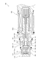
- FIG. 3 is an enlarged cross-sectional view of FIG. 2 illustrating a state in which the first valve is opened in a non-energized state of the capacity control valve of the first embodiment. It is sectional drawing which shows a mode that the 1st valve was obstruct
- FIG. 5 is a cross-sectional view showing a state in which the flow path cross-sectional area of the communication hole is expanded from the state of FIG. 4 in the energized state of the capacity control valve of Example 1. It is sectional drawing which shows a mode that the pressure sensitive valve was obstruct
- FIG. (A)-(c) is an expanded sectional view which shows the mode of engagement of the restriction
- FIG. is there.
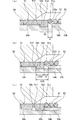
- FIG. 1 is an expanded sectional view which shows the mode of opening and closing of the communicating hole in the capacity
- FIG. 2 is an expanded sectional view which shows the opening / closing structure of the communicating hole in the capacity
- It is sectional drawing which shows a mode that the main valve was obstruct
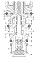
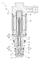
- the capacity control valve according to the first embodiment will be described with reference to FIGS.
- the left and right sides as viewed from the front side of FIG. 2 will be described as the left and right sides of the capacity control valve.
- the capacity control valve V of the present invention is incorporated in a variable capacity compressor M used in an air conditioning system of an automobile or the like, and variably controls the pressure of a working fluid (hereinafter simply referred to as “fluid”) as a refrigerant.
- a working fluid hereinafter simply referred to as “fluid”
- the discharge amount of the variable capacity compressor M is controlled to adjust the air conditioning system to have a desired cooling capacity.
- variable capacity compressor M includes a casing 1 including a discharge chamber 2, a suction chamber 3, a control chamber 4, and a plurality of cylinders 4a.
- the variable capacity compressor M is provided with a communication path (not shown) that directly communicates the control chamber 4 and the suction chamber 3, and the pressure in the suction chamber 3 and the control chamber 4 is balanced in this communication path.
- a fixed orifice is provided for adjustment.
- variable capacity compressor M is connected to a rotating shaft 5 that is rotationally driven by an engine (not shown) installed outside the casing 1 and is eccentrically connected to the rotating shaft 5 in the control chamber 4 by a hinge mechanism 8. And a displacement control valve V which is connected to the swash plate 6 and is connected to the swash plate 6 so as to be reciprocally movable in each cylinder 4a.
- the displacement control valve V is opened and closed by electromagnetic force.
- the swash plate 6 is in a substantially vertical state with respect to the shaft 5, that is, in a state slightly inclined from the vertical.
- the stroke amount of the piston 7 is minimized, the pressure applied to the fluid in the cylinder 4a by the piston 7 is minimized, the amount of fluid discharged into the discharge chamber 2 is reduced, and the cooling capacity of the air conditioning system is minimized. It becomes.
- the capacity control valve V incorporated in the variable capacity compressor M adjusts the current supplied to the coil 86 constituting the solenoid 80, and is the first valve as the main valve in the capacity control valve V. 50.
- the control pressure Pc in 4 is variably controlled.
- the first valve 50 is constituted by a main valve body 51 and a first valve seat 10 a as a main valve seat formed on the inner peripheral surface of the valve housing 10.
- the 1st valve part 51a as a main valve part formed in the direction left end contacts / separates the 1st valve seat 10a.
- the second valve 53 includes a second valve body 52 as a hollow tube and a second valve seat 82 a formed on the left end surface in the axial direction that is the opening end surface of the fixed iron core 82.
- the second valve portion 52a formed on the end surface on the right side in the axial direction of the annular flange portion 52c extending in the outer diameter direction from the substantially outer peripheral surface in the axial direction is in contact with and away from the second valve seat 82a.
- the pressure-sensitive valve 55 includes an adapter 70 of the pressure-sensitive body 60 and a pressure-sensitive valve seat 54a formed at the left end in the axial direction of the pressure-sensitive valve member 54 as a hollow tube. The pressure sensitive valve seat 54a is contacted and separated.
- the capacity control valve V includes a valve housing 10 formed of a metal material or a resin material, and a main valve disposed (internally fitted) inside the valve housing 10 so as to be capable of reciprocating in the axial direction.
- the pressure body 60 mainly includes a main valve body 51, a second valve body 52, and a solenoid 80 that drives the pressure-sensitive valve member 54 and is connected to the valve housing 10.
- the solenoid 80 has a casing 81 having an opening 81 a that opens to the left in the axial direction, and is inserted from the left in the axial direction with respect to the opening 81 a of the casing 81.
- the casing 81 is formed with a concave portion 81b that is recessed from the radial center at the left end in the axial direction to the right in the axial direction, and the axial right end portion of the valve housing 10 is fitted and fixed to the concave portion 81b.
- the fixed iron core 82 is formed of a rigid body made of a magnetic material such as iron or silicon steel, and extends in the axial direction and has a cylindrical portion 82b in which an insertion hole 82c is inserted, and a left end in the axial direction of the cylindrical portion 82b. And an annular flange portion 82d extending in the outer radial direction from the outer peripheral surface of the portion, and a concave portion 82e is formed that is recessed axially rightward from the radial center of the axial left end of the cylindrical portion 82b.
- the valve housing 10 has a bottomed substantially cylindrical shape by press-fitting a partition adjusting member 11 at the left end in the axial direction.
- a main valve body 51, a second valve body 52, and a pressure-sensitive valve member 54 are disposed so as to be capable of reciprocating in the axial direction, and a part of the inner peripheral surface of the valve housing 10 has a main valve body.
- a small-diameter guide surface 10b on which the outer peripheral surface of 51 can slide is formed.
- the partition adjusting member 11 can adjust the urging force of the pressure sensitive body 60 by adjusting the installation position of the valve housing 10 in the axial direction.
- a first valve chamber 20 in which the left side in the axial direction, which is the first valve portion 51 a side of the main valve body 51, is arranged, and a right side in the axial direction, which is the back pressure side of the main valve body 51.
- a second valve chamber 30 is formed, and a pressure sensitive chamber 40 is formed at a position opposite to the second valve chamber 30 in the axial direction with respect to the first valve chamber 20.
- the second valve chamber 30 includes an outer peripheral surface on the back pressure side of the main valve body 51, an outer peripheral surface of the second valve body 52, an axial left end surface that is an opening end surface of the fixed iron core 82, a recess 82e, a valve housing And an inner peripheral surface on the right side in the axial direction of the ten guide surfaces 10b.
- the valve housing 10 includes a Pd port 12 that communicates the first valve chamber 20 and the discharge chamber 2 of the variable displacement compressor M, a second valve chamber 30 and the suction chamber 3 of the variable displacement compressor M. And a Ps port 14 that communicates the pressure sensing chamber 40 and the control chamber 4 of the variable displacement compressor M.
- the main valve body 51 is configured in a cylindrical shape, and includes a cylindrical portion 51b, a first valve portion 51a formed on the left outer diameter side in the axial direction of the cylindrical portion 51b, and a cylindrical portion.
- a sliding contact portion 51c that projects annularly from the inner peripheral surface of the left end portion in the axial direction of 51b in the inner diameter direction and has a smaller inner diameter than the cylindrical portion 51b, and an inner diameter direction from the inner peripheral surface of the right end portion in the axial direction of the cylindrical portion 51b
- a regulating portion 51d that protrudes in an annular shape and has an inner diameter that is smaller than the sliding contact portion 51c, and is externally fitted to the pressure-sensitive valve member 54 so as to be movable in the axial direction.
- the main valve body 51 is formed so that the inner diameter of the sliding contact portion 51c is small, so that the inner peripheral surface of the cylindrical portion 51b and the pressure sensitive valve member 54 are in a state of being externally fitted to the pressure sensitive valve member 54.
- An annular gap that is radially separated is formed between the outer peripheral surface of the cylindrical portion 54 b and the main valve body 51 is easy to move relative to the pressure-sensitive valve member 54 in the axial direction.
- the pressure-sensitive valve member 54 has a substantially cylindrical shape and a substantially turret shape in a side view, and extends from the outer peripheral surface of the cylindrical portion 54 b and the axial left end of the cylindrical portion 54 b in the outer diameter direction.
- a flange portion 54c having a pressure-sensitive valve seat 54a at the left end in the axial direction, and a mounting portion 54d formed at the right end portion in the axial direction of the cylindrical portion 54b and having a smaller diameter than the cylindrical portion 54b.
- the cylindrical portion 54b has a main valve body.
- the outer diameter is slightly smaller than the inner diameter of the sliding contact portion 51c of 51.
- the mounting portion 54d is formed so that the outer diameter is slightly smaller than the inner diameter of the restricting portion 51d of the main valve body 51, and the axial dimension is longer than the restricting portion 51d of the main valve body 51. Yes.
- the mounting portion 54d of the pressure-sensitive valve member 54 is movable in the axial direction toward the inner diameter side of the regulating portion 51d of the main valve body 51.
- the axially right end portion of the mounting portion 54d is inserted from the opening portion on the right side in the axial direction of the restricting portion 51d of the main valve body 51, and the engaging portion on the right side in the axial direction of the cylindrical portion 54b of the pressure-sensitive valve member 54 is inserted.
- the end surface 54e of the main valve body 51 can be engaged with a regulating end surface 51f as an engaging portion on the left side in the axial direction of the regulating portion 51d of the main valve body 51.
- the second valve body 52 is configured in a substantially cylindrical shape with a flange, and has an annular shape extending in the outer diameter direction from the outer peripheral surface of the cylindrical portion 52 b and the substantially central portion in the axial direction of the cylindrical portion 52 b. And a mounting recess 52d that is recessed axially rightward from the radial center of the left end in the axial direction of the cylindrical portion 52b, and the right end in the axial direction of the mounting portion 54d of the pressure sensitive valve member 54 with respect to the mounting recess 52d.
- the part is inserted and fixed, and the second valve body 52 and the pressure-sensitive valve member 54 are integrally connected.
- a drive rod 83 is connected and fixed to the right end of the second valve body 52 in the axial direction, so that the main valve body 51, the second valve body 52, and the pressure-sensitive valve member 54 can move together in the axial direction. ing.
- a coil spring 57 as a spring is fitted on the cylindrical portion 52b on the left side in the axial direction of the flange portion 52c of the second valve body 52, and the left end in the axial direction of the coil spring 57 is the restricting portion of the main valve body 51.
- 51d is in contact with the outer diameter side of the regulating end surface 51g as the engagement portion on the right side in the axial direction, and the axial right end of the coil spring 57 is in contact with the end surface on the left in the axial direction of the flange portion 52c of the second valve body 52.
- the coil spring 57 is axially leftward so that the axially restricted left end surface 51f of the restricting portion 51d of the main valve body 51 is engaged with the axially right end surface 54e of the cylindrical portion 54b of the pressure sensitive valve member 54.
- the urging power of is granted.
- the coil spring 57 is set to have a smaller spring constant than the coil spring 62 provided in the pressure sensitive body 60.
- the second valve body 52 and the pressure-sensitive valve member 54 are integrally connected, so that the outer periphery of the mounting portion 54d of the pressure-sensitive valve member 54 to which the regulating portion 51d of the main valve body 51 is fitted is annular.
- a concave groove 58 (see FIG. 7) is formed.
- the concave groove 58 includes an outer peripheral surface of the mounting portion 54d of the pressure-sensitive valve member 54, an axially right end surface 54e of the cylindrical portion 54b of the pressure-sensitive valve member 54, and an axially left end surface of the cylindrical portion 52b of the second valve body 52.
- the axial position of the main valve body 51 that moves relative to the second valve body 52 and the pressure-sensitive valve member 54 in the axial direction, that is, the restricting portion 51d, is determined by the recessed groove 58.
- the main valve is in a state where the restriction end surface 51f on the left side in the axial direction of the restriction portion 51d of the main valve body 51 is in contact with the end surface 54e on the right side in the axial direction of the cylindrical portion 54b of the pressure sensitive valve member 54 by the biasing force of the coil spring 57
- the right end of the body 51 in the axial direction that is, the restriction end surface 51g on the right in the axial direction of the restriction 51d of the main valve body 51
- the left end of the second valve body 52 in the axial direction that is, the left side in the axial direction of the cylindrical portion 52b of the second valve body 52.
- the axial separation dimension A between the regulating end surface 51g of the main valve body 51 and the end surface 52e of the second valve body 52 is the axis of the opening of the communication hole 90 as an auxiliary communication path described later.
- the dimension is set to approximately half of the right side of the direction. That is, after the first valve 50 is closed, the pressure-sensitive valve member 54 is further movable in the axial direction by the separation dimension A.
- a hollow communication passage 56 penetrating in the axial direction is formed in the second valve body 52 and the pressure-sensitive valve member 54 by connecting a hollow hole.
- the hollow communication passage 56 communicates with the inside of the recess 82e of the fixed core 82 through a plurality of through holes 52f that penetrate in the radial direction in the cylindrical portion 52b on the right side in the axial direction of the flange portion 52c of the second valve body 52. ing.
- the hollow communication passage 56 communicates with the first valve chamber 20 and / or the pressure sensitive chamber 40 via a plurality of communication holes 90 penetrating in the radial direction at the left end in the axial direction of the cylindrical portion 54 b of the pressure sensitive valve member 54. ing.
- the restriction end surface 51 f on the left side in the axial direction of the restriction portion 51 d of the main valve body 51 becomes the end surface 54 e on the right side in the axial direction of the cylindrical portion 54 b of the pressure sensitive valve member 54.
- the communication hole 90 is closed approximately half on the right side in the axial direction of the opening, preferably more than 1/2 of the opening, by the sliding contact portion 51c of the main valve body 51 fitted on the pressure-sensitive valve member 54. (See FIG. 8A).
- the pressure sensitive body 60 is mainly composed of a bellows core 61 in which a coil spring 62 is incorporated, and an adapter 70 formed at the right end of the bellows core 61 in the axial direction.
- the left end in the axial direction of 61 is fixed to the partition adjusting member 11.
- the pressure sensitive body 60 is disposed in the pressure sensitive chamber 40, and the axial right end 70 a of the adapter 70 is seated on the pressure sensitive valve seat 54 a of the pressure sensitive valve member 54 by the biasing force of the coil spring 62 and the bellows core 61. It is supposed to be.
- the suction pressure Ps in the hollow communication passage 56 is high, the pressure-sensitive body 60 contracts due to the surrounding fluid pressure, and the axial right end 70a of the adapter 70 is separated from the pressure-sensitive valve seat 54a of the pressure-sensitive valve member 54.
- the pressure sensitive valve 55 is opened (see FIGS. 4 and 5).
- the control pressure Pc is quickly released to the second valve chamber 30 through the hollow communication passage 56 and the through hole 52f of the second valve body 52. be able to.
- the capacity control valve V in the non-energized state, the capacity control valve V is axially rightward due to the urging force of the coil spring 85 and the urging force of the coil spring 62 and the bellows core 61 with the movable core 84 constituting the solenoid 80.
- the drive rod 83, the main valve body 51, the second valve body 52, and the pressure-sensitive valve member 54 move to the right in the axial direction, and the second valve portion 52a of the second valve body 52 is fixed iron core.
- the second valve seat 82 is seated on the second valve seat 82a, and the second valve 53 is closed.
- the first valve portion 51a of the main valve body 51 is separated from the first valve seat 10a formed on the inner peripheral surface of the valve housing 10, and the first valve 50 is opened.
- the axially left restricting end surface 51f of the restricting portion 51d of the main valve body 51 is moved to the right side in the axial direction of the cylindrical portion 54b of the pressure sensitive valve member 54 by the urging force of the coil spring 57.
- the communication hole 90 is substantially the right side in the axial direction of the opening by the sliding contact portion 51c of the main valve body 51 fitted on the pressure sensitive valve member 54. Half is closed (see FIG. 8A).
- the fluid in the discharge chamber 2 of the variable displacement compressor M passes through the displacement control valve V from the discharge chamber 2 when the first valve 50 is opened. Then, it flows into the control room 4. This is because the discharge pressure Pd is higher than the control pressure Pc.
- the control pressure Pc is higher than the control pressure Pc before the non-energized state due to the discharge pressure Pd flowing into the control chamber 4, and is higher than the suction pressure Ps.
- the capacity control valve V is energized to generate a magnetic force by energizing the coil 86 of the solenoid 80 from the non-energized state (the state where the first valve 50 is opened) shown in FIGS. 51, the second valve body 52, and the pressure-sensitive valve member 54 move leftward in the axial direction, whereby the first valve seat 51a of the main valve body 51 is formed on the inner peripheral surface of the valve housing 10. 10a is seated and the first valve 50 is closed (see FIG. 4). At this time, the second valve portion 52a of the second valve body 52 is separated from the second valve seat 82a formed on the opening end surface of the fixed iron core 82, and the second valve 53 is opened.
- the main valve body 51 is moved against the second valve body 52 and the pressure-sensitive valve member 54 by the urging force of the coil spring 57 until the first valve 50 is closed from the non-energized state to the energized state.
- they move integrally leftward in the axial direction without relative movement in the axial direction (see FIGS. 7B and 8B).
- the second valve body 52 and the pressure-sensitive valve member 54 move to the left in the axial direction against the urging force of the coil spring 57 (see FIG. 5). Not only the driving force by the solenoid 80, but also when the force by the suction pressure Ps that moves the second valve body 52 and the pressure-sensitive valve member 54 to the right in the axial direction exceeds the urging force of the coil spring 57, the second The valve body 52 and the pressure sensitive valve member 54 move to the left in the axial direction.
- the shaft of the cylindrical portion 54b of the pressure-sensitive valve member 54 extends from the restriction end surface 51f on the left side in the axial direction of the restriction portion 51d of the main valve body 51.
- the right end face 54e is spaced apart in the axial direction and disengaged, and the right restricting end face 51g of the restricting part 51d of the main valve body 51 is the end face 52e on the left side in the axial direction of the cylindrical part 52b of the second valve body 52.
- the main valve body 51 moves relative to the second valve body 52 and the pressure-sensitive valve member 54 relative to the second valve body 52 and the pressure-sensitive valve member 54 to the right in the axial direction by the dimension A (see FIG. 7C).
- the dimension A that is, the axial right side of the opening of the communication hole 90 is reached until the axial left end of the sliding contact portion 51c of the main valve body 51 does not overlap the communication hole 90 formed in the cylindrical portion 54b of the pressure sensitive valve member 54.
- the entire opening of the communication hole 90 of the pressure-sensitive valve member 54 is opened by the relative movement to the right in the axial direction by approximately half (see FIG. 8C).
- the suction pressure Ps of the suction chamber 3 slightly decreases due to the stroke of the piston 7, so that the control pressure Pc of the control chamber 4 and the suction pressure Ps of the suction chamber 3 are reduced. Due to the pressure difference, the flow of fluid from the Pc port 14 through the communication hole 90 to the Ps port 13 through the hollow communication passage 56 (shown by solid arrows in FIGS. 5 and 6), and from the pressure sensing chamber 40 A fluid flow toward the Ps port 13 through the hollow communication passage 56 via the pressure sensitive valve 55 is generated (indicated by solid arrows in FIGS. 4 and 5).
- the capacity control valve V of the present embodiment opens the pressure-sensitive valve 55 communicating with the hollow communication path 56 and starts the second valve body 52 and the pressure-sensitive valve member 54 when the variable displacement compressor M is started.
- the main valve body 51 is relatively moved in the axial direction to widen the flow passage cross-sectional area of the communication hole 90 communicating with the hollow communication passage 56, thereby discharging the liquefied fluid in a short time and responsiveness at start-up. Can be increased.
- the pressure sensing body 60 is extended, so that the right end 70a in the axial direction of the adapter 70 is seated on the pressure sensing valve seat 54a of the pressure sensing valve member 54, and the suction pressure is increased. Even when Ps is low and the pressure-sensitive valve 55 does not open, the state in which the cross-sectional area of the communication hole 90 is expanded can be maintained, so that the liquefied fluid can be reliably discharged (see FIG. 6). ).
- the mode of normal control of the capacity control valve V when the variable capacity compressor M is continuously driven will be described.
- the case where normal control is performed from the state where the control pressure Pc and the suction pressure Ps are balanced and the control chamber 4 reaches the maximum capacity will be described.
- the capacity control valve V closes the first valve 50 in the maximum capacity state, and moves the main valve body 51 in the axial direction with respect to the second valve body 52 and the pressure-sensitive valve member 54.
- the Ps port 13 By maintaining the state in which the flow passage cross-sectional area of the communication hole 90 is expanded by relative movement, the Ps port 13 can be communicated with the Pc port 14 by the hollow communication path 56 through the communication hole 90, so that the control pressure It is easy to maintain Pc and suction pressure Ps at equal pressure (same pressure). Therefore, the stroke of the piston 7 in the cylinder 4a of the control chamber 4 can be stabilized, the maximum capacity state can be maintained, and the operation efficiency can be improved.
- the current supplied to the coil 86 of the solenoid 80 is controlled to be small, and the first valve 50 is kept closed.
- the main valve body 51 is relatively moved in the axial direction relative to the second valve body 52 and the pressure-sensitive valve member 54 to narrow the flow passage cross-sectional area of the communication hole 90 (see FIG. 8B). Since the flow rate from the Pc port 14 to the Ps port 13 is reduced and the control pressure Pc can be set to a pressure (Pc> Ps) higher than the suction pressure Ps, the control pressure Pc in the control chamber 4 is increased, and the variable capacity type The compressor M can be reduced to a desired output, and controllability is high.
- the auxiliary communication passage for communicating the Pc port 14 and the Ps port 13 is constituted by the communication hole 90 of the pressure sensitive valve member 54 communicating with the hollow communication passage 56.
- An auxiliary communication path can be formed in the control valve V. Furthermore, since the communication hole 90 is provided in the small-diameter cylindrical portion 54b of the pressure-sensitive valve member 54, the main valve body 51 to be externally fitted can be reduced in size.
- the main valve body 51 is externally fitted to the second valve body 52 and the pressure sensitive valve member 54 via a coil spring 57 so as to be movable in the axial direction. Therefore, the flow passage cross-sectional area of the communication hole 90 can be changed by the cooperation of the main valve body 51 and the communication hole 90.
- the structure is simple. Furthermore, since the main valve body 51 is fitted to the cylindrical portion 54b of the pressure-sensitive valve member 54 and is fitted to the guide surface 10b of the valve housing 10, the main valve body 51 is moved in the axial direction. It can be made smoother.
- the main valve body 51 is configured such that the regulating portion 51d of the main valve body 51 is externally fitted to the concave groove 58 formed on the outer periphery of the mounting portion 54d of the pressure-sensitive valve member 54, whereby the second valve is engaged by the engaging portion. Since the position in the axial direction when the communication hole 90 is opened and closed with respect to the body 52 and the pressure sensitive valve member 54 is restricted, the structure is simple.
- the communication hole 290 as an auxiliary communication path is provided on the outer periphery of the cylindrical portion 254b of the pressure-sensitive valve member 254 to which the sliding contact portion 251c of the main valve body 251 is fitted.
- the annular groove portion 291 By forming the annular groove portion 291 corresponding to the axial position, the open / close structure of the communication hole 290 by the main valve body 251 forms a so-called spool valve structure.
- the capacity control valve V includes the communication hole 90 formed in the cylindrical portion 54 b of the pressure-sensitive valve member 54, by the sliding contact portion 51 c of the main valve body 51 that is externally fitted to the pressure-sensitive valve member 54.
- the present invention is not limited thereto, and the opening of the communication hole 90 is fully closed by the sliding contact portion 51c of the main valve body 51. May be.
- the restricting portion 51 d of the main valve body 51 is fitted in the recessed groove 58, and the respective engaging portions engage with each other, so that the second valve body 52 and the pressure-sensitive valve member 54 are pivoted.
- the axial position of the main valve body 51 that moves relative to the direction has been described as being determined.
- the present invention is not limited to this.
- the axial position of the main valve body in a non-energized state may It may be configured to be determined by engaging the engaging portion of the restricting portion extending in the outer diameter direction from the engaging portion with the engaging portion provided on the inner peripheral surface of the valve housing 10.
- the second valve body 52 and the pressure-sensitive valve member 54 constituting the hollow tube may be integrally formed.
- the auxiliary communication passage is formed after the first valve portion 51a of the main valve body 51 is seated on the first valve seat 10a formed on the inner peripheral surface of the valve housing 10 and the first valve 50 is closed.
- the cross-sectional area may be a through hole provided in the adapter 70 constituting the pressure sensitive valve 55 or an axial hole provided in the valve housing 10.
- the 2nd valve does not need to be provided and the 2nd valve part 52a of the 2nd valve body 52 should just function as a support member which receives the load of an axial direction, and does not necessarily require a sealing function. .
- the second valve chamber 30 may be provided on the side opposite to the solenoid 80 in the axial direction, and the pressure sensitive chamber 40 may be provided on the solenoid 80 side.
- the coil spring 57 is not limited to a compression spring, and may be a tension spring or other than a coil shape.
- the pressure-sensitive body 60 may not use a coil spring inside.
Landscapes
- Engineering & Computer Science (AREA)
- General Engineering & Computer Science (AREA)
- Mechanical Engineering (AREA)
- Physics & Mathematics (AREA)
- Thermal Sciences (AREA)
- Compressors, Vaccum Pumps And Other Relevant Systems (AREA)
- Control Of Positive-Displacement Pumps (AREA)
- Magnetically Actuated Valves (AREA)
Abstract
Description
流体の容量を制御する容量制御弁であって、
バルブハウジングと、
主弁座とソレノイドの駆動力により駆動される主弁体の主弁部との接離により制御圧の制御流体が通過するPcポートと吐出圧の吐出流体が通過するPdポートとの間を開閉する主弁と、
周囲の圧力により開放する感圧弁と、
前記感圧弁の一部を成し該感圧弁の開放により中空連通路を介して前記Pcポートと吸入圧の吸入流体が通過するPsポートとを連通させる中空管と、
前記感圧弁とは別に前記Pcポートと前記Psポートとを連通させる補助連通路が形成されており、該補助連通路は、前記主弁の閉塞後に流路断面積を広くできることを特徴としている。
この特徴によれば、容量可変型圧縮機の起動時に補助連通路の流路断面積を広くして流体を迅速に排出できるとともに、通常制御時に補助連通路の流路断面積を狭くして制御性を高めることができる。
これによれば、通常制御時にPcポートとPsポートとの流量が絞られることにより制御性が良い。
これによれば、簡単な構造により補助連通路を形成できる。
これによれば、主弁体と連通孔の協動により補助連通路の流路断面積を変更でき構造が簡単であるとともに、主弁体の移動が円滑である。
これによれば、主弁体の移動がより円滑である。
これによれば、主弁体は、係合部によって中空管に対して連通孔の閉塞方向および開放方向への移動位置が規制されるため構造が簡単である。
2 吐出室
3 吸入室
4 制御室
10 バルブハウジング
10a 第1弁座(主弁座)
10b ガイド面
11 仕切調整部材
12 Pdポート
13 Psポート
14 Pcポート
20 第1弁室
30 第2弁室
40 感圧室
50 第1弁
51 主弁体
51a 第1弁部(主弁部)
51b 円筒部
51c 摺接部
51d 規制部
51f 規制端面(係合部)
51g 規制端面(係合部)
52 第2弁体(中空管)
52a 第2弁部
52b 円筒部
52c フランジ部
52d 取付凹部
52e 端面(係合部)
52f 貫通孔
53 第2弁
54 感圧弁部材(中空管)
54a 感圧弁座
54b 円筒部
54c フランジ部
54d 取付部
54e 端面(係合部)
55 感圧弁
56 中空連通路
57 コイルスプリング(バネ)
58 凹溝
60 感圧体
61 ベローズコア
62 コイルスプリング
70 アダプタ
70a 軸方向右端
82 固定鉄心
82a 第2弁座
90 連通孔(補助連通路)
251 主弁体
254 感圧弁部材(中空管)
254b 円筒部
290 連通孔(補助連通路)
291 環状溝部
Pc 制御圧力
Pd 吐出圧力
Ps 吸入圧力
V 容量制御弁
Claims (6)
- 流体の容量を制御する容量制御弁であって、
バルブハウジングと、
主弁座とソレノイドの駆動力により駆動される主弁体の主弁部との接離によりPcポートとPdポートとの間を開閉する主弁と、
周囲の圧力により開放する感圧弁と、
前記感圧弁の一部を成し該感圧弁の開放により中空連通路を介して前記PcポートとPsポートとを連通させる中空管と、
前記感圧弁とは別に前記Pcポートと前記Psポートとを連通させる補助連通路が形成されており、該補助連通路は、前記主弁の閉塞後に流路断面積を広くできることを特徴とする容量制御弁。 - 前記流路断面積は、前記主弁の閉塞時に全開時の1/2以下となる請求項1に記載の容量制御弁。
- 前記補助連通路は、前記中空管の前記中空連通路に連通する連通孔である請求項1または2に記載の容量制御弁。
- 前記主弁体は、前記中空管に対してバネを介して移動可能に外嵌されており、該主弁体は、前記中空管に対して相対移動して前記連通孔の開口の少なくとも一部を塞いでいる請求項3に記載の容量制御弁。
- 前記主弁体は、前記バルブハウジングに内嵌されている請求項1ないし4のいずれかに記載の容量制御弁。
- 前記主弁体と前記中空管には、互いの相対移動方向に係合する係合部が形成されている請求項1ないし5のいずれかに記載の容量制御弁。
Priority Applications (5)
| Application Number | Priority Date | Filing Date | Title |
|---|---|---|---|
| KR1020207024987A KR102352195B1 (ko) | 2018-02-27 | 2019-02-26 | 용량 제어 밸브 |
| JP2020503506A JP7139084B2 (ja) | 2018-02-27 | 2019-02-26 | 容量制御弁 |
| EP19760096.8A EP3760864B1 (en) | 2018-02-27 | 2019-02-26 | Capacity control valve |
| US16/969,175 US11873804B2 (en) | 2018-02-27 | 2019-02-26 | Capacity control valve |
| CN201980012733.8A CN111742141B (zh) | 2018-02-27 | 2019-02-26 | 容量控制阀 |
Applications Claiming Priority (2)
| Application Number | Priority Date | Filing Date | Title |
|---|---|---|---|
| JP2018033902 | 2018-02-27 | ||
| JP2018-033902 | 2018-02-27 |
Publications (1)
| Publication Number | Publication Date |
|---|---|
| WO2019167912A1 true WO2019167912A1 (ja) | 2019-09-06 |
Family
ID=67805767
Family Applications (1)
| Application Number | Title | Priority Date | Filing Date |
|---|---|---|---|
| PCT/JP2019/007187 Ceased WO2019167912A1 (ja) | 2018-02-27 | 2019-02-26 | 容量制御弁 |
Country Status (6)
| Country | Link |
|---|---|
| US (1) | US11873804B2 (ja) |
| EP (1) | EP3760864B1 (ja) |
| JP (1) | JP7139084B2 (ja) |
| KR (1) | KR102352195B1 (ja) |
| CN (1) | CN111742141B (ja) |
| WO (1) | WO2019167912A1 (ja) |
Cited By (21)
| Publication number | Priority date | Publication date | Assignee | Title |
|---|---|---|---|---|
| WO2020116436A1 (ja) * | 2018-12-04 | 2020-06-11 | イーグル工業株式会社 | 容量制御弁 |
| WO2020116435A1 (ja) * | 2018-12-04 | 2020-06-11 | イーグル工業株式会社 | 容量制御弁 |
| WO2020121764A1 (en) * | 2018-12-13 | 2020-06-18 | Eagle Industry Co., Ltd. | Displacement control valve |
| WO2021215345A1 (ja) * | 2020-04-23 | 2021-10-28 | イーグル工業株式会社 | 容量制御弁 |
| JPWO2021241478A1 (ja) * | 2020-05-25 | 2021-12-02 | ||
| JPWO2021241477A1 (ja) * | 2020-05-25 | 2021-12-02 | ||
| US11225962B2 (en) | 2018-05-23 | 2022-01-18 | Eagle Industry Co., Ltd. | Capacity control valve |
| US11378194B2 (en) | 2018-11-07 | 2022-07-05 | Eagle Industry Co., Ltd. | Capacity control valve |
| US11473683B2 (en) | 2018-08-08 | 2022-10-18 | Eagle Industry Co., Ltd. | Capacity control valve |
| US11480166B2 (en) | 2018-07-13 | 2022-10-25 | Eagle Industry Co., Ltd. | Capacity control valve |
| US11536257B2 (en) | 2018-07-12 | 2022-12-27 | Eagle Industry Co., Ltd. | Capacity control valve |
| US11555489B2 (en) | 2018-07-12 | 2023-01-17 | Eagle Industry Co., Ltd. | Capacity control valve |
| US11598437B2 (en) | 2019-03-01 | 2023-03-07 | Eagle Industry Co., Ltd. | Capacity control valve |
| US11802552B2 (en) | 2019-07-12 | 2023-10-31 | Eagle Industry Co., Ltd. | Capacity control valve |
| US11841090B2 (en) | 2019-04-03 | 2023-12-12 | Eagle Industry Co., Ltd. | Capacity control valve |
| US11873805B2 (en) | 2018-08-08 | 2024-01-16 | Eagle Industry Co., Ltd. | Capacity control valve |
| US11927275B2 (en) | 2019-04-03 | 2024-03-12 | Eagle Industry Co., Ltd. | Capacity control valve |
| US11994120B2 (en) | 2018-07-12 | 2024-05-28 | Eagle Industry Co., Ltd. | Capacity control valve |
| US12012948B2 (en) | 2018-08-08 | 2024-06-18 | Eagle Industry Co., Ltd. | Capacity control valve |
| US12129840B2 (en) | 2019-10-28 | 2024-10-29 | Eagle Industry Co., Ltd. | Capacity control valve |
| US12292130B2 (en) | 2019-01-21 | 2025-05-06 | Eagle Industry Co., Ltd. | Capacity control valve |
Citations (5)
| Publication number | Priority date | Publication date | Assignee | Title |
|---|---|---|---|---|
| WO2007119380A1 (ja) * | 2006-03-15 | 2007-10-25 | Eagle Industry Co., Ltd. | 容量制御弁 |
| WO2014119594A1 (ja) * | 2013-01-31 | 2014-08-07 | イーグル工業株式会社 | 容量制御弁 |
| JP2014190247A (ja) * | 2013-03-27 | 2014-10-06 | Tgk Co Ltd | 可変容量圧縮機用制御弁 |
| WO2017057160A1 (ja) * | 2015-09-29 | 2017-04-06 | 株式会社ヴァレオジャパン | 可変容量型圧縮機の制御弁 |
| WO2017159553A1 (ja) * | 2016-03-17 | 2017-09-21 | イーグル工業株式会社 | 容量制御弁 |
Family Cites Families (41)
| Publication number | Priority date | Publication date | Assignee | Title |
|---|---|---|---|---|
| US3297048A (en) | 1963-10-10 | 1967-01-10 | Imhof Augustin | Safety valve |
| AU615200B2 (en) | 1987-06-30 | 1991-09-26 | Sanden Corporation | Refrigerant circuit with passageway control mechanism |
| CH681384A5 (ja) | 1989-07-13 | 1993-03-15 | Balzers Hochvakuum | |
| JP3089816B2 (ja) | 1992-04-28 | 2000-09-18 | 株式会社豊田自動織機製作所 | 斜板式可変容量圧縮機 |
| JPH06200875A (ja) | 1993-01-08 | 1994-07-19 | Toyota Autom Loom Works Ltd | 揺動斜板式可変容量圧縮機 |
| JP3175536B2 (ja) * | 1995-06-13 | 2001-06-11 | 株式会社豊田自動織機製作所 | クラッチレス可変容量型圧縮機における容量制御構造 |
| JP3490557B2 (ja) * | 1995-10-31 | 2004-01-26 | 株式会社テージーケー | 容量可変圧縮機の容量制御装置 |
| US6010312A (en) | 1996-07-31 | 2000-01-04 | Kabushiki Kaisha Toyoda Jidoshokki Seiksakusho | Control valve unit with independently operable valve mechanisms for variable displacement compressor |
| JP2000064957A (ja) | 1998-08-17 | 2000-03-03 | Toyota Autom Loom Works Ltd | 容量可変型斜板式圧縮機および抜き側制御弁 |
| JP3583951B2 (ja) | 1999-06-07 | 2004-11-04 | 株式会社豊田自動織機 | 容量制御弁 |
| JP2001073939A (ja) | 1999-08-31 | 2001-03-21 | Toyota Autom Loom Works Ltd | 容量可変型圧縮機の制御弁及び容量可変型圧縮機 |
| JP2001099060A (ja) | 1999-10-04 | 2001-04-10 | Fuji Koki Corp | 可変容量型圧縮機用制御弁 |
| JP2001132632A (ja) * | 1999-11-10 | 2001-05-18 | Toyota Autom Loom Works Ltd | 容量可変型圧縮機の制御弁 |
| JP3941303B2 (ja) | 1999-11-17 | 2007-07-04 | 株式会社豊田自動織機 | 空調装置 |
| JP3780784B2 (ja) | 1999-11-25 | 2006-05-31 | 株式会社豊田自動織機 | 空調装置および容量可変型圧縮機の制御弁 |
| JP4242624B2 (ja) | 2002-09-26 | 2009-03-25 | イーグル工業株式会社 | 容量制御弁及びその制御方法 |
| JP2005069072A (ja) | 2003-08-22 | 2005-03-17 | Eagle Ind Co Ltd | 容量制御弁 |
| JP2005291142A (ja) | 2004-04-02 | 2005-10-20 | Zexel Valeo Climate Control Corp | 可変容量型圧縮機の制御装置及び圧力制御弁 |
| JP4431462B2 (ja) | 2004-08-10 | 2010-03-17 | 株式会社鷺宮製作所 | 斜板式容量可変型圧縮機および電磁制御弁 |
| US8021124B2 (en) | 2005-02-24 | 2011-09-20 | Eagle Industry Co., Ltd. | Capacity control valve |
| JP2006307828A (ja) | 2005-03-31 | 2006-11-09 | Tgk Co Ltd | 可変容量圧縮機用制御弁 |
| EP1895162B9 (en) | 2005-06-22 | 2013-05-29 | Eagle Industry Co., Ltd. | Capacity control valve |
| CN102792025B (zh) | 2010-03-16 | 2015-03-04 | 伊格尔工业股份有限公司 | 容量控制阀 |
| JP5878703B2 (ja) | 2010-09-06 | 2016-03-08 | 株式会社不二工機 | 可変容量型圧縮機用制御弁 |
| KR101375294B1 (ko) | 2010-12-09 | 2014-03-17 | 이구루코교 가부시기가이샤 | 용량 제어 밸브 |
| JP5665722B2 (ja) | 2011-11-17 | 2015-02-04 | 株式会社豊田自動織機 | 容量制御弁 |
| JP6064132B2 (ja) | 2012-10-09 | 2017-01-25 | 株式会社テージーケー | 複合弁 |
| JP6216950B2 (ja) * | 2012-12-11 | 2017-10-25 | 株式会社テージーケー | 可変容量圧縮機用制御弁および制御弁 |
| KR101689241B1 (ko) | 2012-12-12 | 2016-12-23 | 이구루코교 가부시기가이샤 | 용량 제어 밸브 |
| JP6206274B2 (ja) | 2014-03-19 | 2017-10-04 | 株式会社豊田自動織機 | 容量制御弁 |
| JP6383720B2 (ja) * | 2015-12-16 | 2018-08-29 | 株式会社不二工機 | 可変容量型圧縮機用制御弁 |
| JP6663227B2 (ja) | 2016-01-19 | 2020-03-11 | サンデン・オートモーティブコンポーネント株式会社 | 可変容量圧縮機の容量制御弁 |
| KR20170093349A (ko) * | 2016-02-05 | 2017-08-16 | 주식회사 뉴로스 | 가변용량 압축기의 전자제어밸브 |
| US10612534B2 (en) | 2016-02-22 | 2020-04-07 | Kabushiki Kaisha Toyota Jidoshokki | Variable displacement swash plate type compressor |
| JP6714274B2 (ja) * | 2016-06-13 | 2020-06-24 | 株式会社テージーケー | 可変容量圧縮機用制御弁 |
| JP6626789B2 (ja) * | 2016-06-28 | 2019-12-25 | 株式会社不二工機 | 可変容量型圧縮機用制御弁 |
| JP6647156B2 (ja) * | 2016-06-28 | 2020-02-14 | 株式会社不二工機 | 可変容量型圧縮機用制御弁 |
| JP2018040385A (ja) | 2016-09-05 | 2018-03-15 | 株式会社テージーケー | 電磁弁 |
| WO2019146674A1 (ja) | 2018-01-26 | 2019-08-01 | イーグル工業株式会社 | 容量制御弁 |
| CN111712638B (zh) | 2018-02-15 | 2022-05-03 | 伊格尔工业股份有限公司 | 容量控制阀 |
| CN111684157B (zh) | 2018-02-15 | 2022-05-03 | 伊格尔工业股份有限公司 | 容量控制阀 |
-
2019
- 2019-02-26 JP JP2020503506A patent/JP7139084B2/ja active Active
- 2019-02-26 KR KR1020207024987A patent/KR102352195B1/ko active Active
- 2019-02-26 US US16/969,175 patent/US11873804B2/en active Active
- 2019-02-26 EP EP19760096.8A patent/EP3760864B1/en active Active
- 2019-02-26 WO PCT/JP2019/007187 patent/WO2019167912A1/ja not_active Ceased
- 2019-02-26 CN CN201980012733.8A patent/CN111742141B/zh active Active
Patent Citations (6)
| Publication number | Priority date | Publication date | Assignee | Title |
|---|---|---|---|---|
| WO2007119380A1 (ja) * | 2006-03-15 | 2007-10-25 | Eagle Industry Co., Ltd. | 容量制御弁 |
| JP5167121B2 (ja) | 2006-03-15 | 2013-03-21 | イーグル工業株式会社 | 容量制御弁 |
| WO2014119594A1 (ja) * | 2013-01-31 | 2014-08-07 | イーグル工業株式会社 | 容量制御弁 |
| JP2014190247A (ja) * | 2013-03-27 | 2014-10-06 | Tgk Co Ltd | 可変容量圧縮機用制御弁 |
| WO2017057160A1 (ja) * | 2015-09-29 | 2017-04-06 | 株式会社ヴァレオジャパン | 可変容量型圧縮機の制御弁 |
| WO2017159553A1 (ja) * | 2016-03-17 | 2017-09-21 | イーグル工業株式会社 | 容量制御弁 |
Non-Patent Citations (1)
| Title |
|---|
| See also references of EP3760864A4 |
Cited By (44)
| Publication number | Priority date | Publication date | Assignee | Title |
|---|---|---|---|---|
| US11225962B2 (en) | 2018-05-23 | 2022-01-18 | Eagle Industry Co., Ltd. | Capacity control valve |
| US11555489B2 (en) | 2018-07-12 | 2023-01-17 | Eagle Industry Co., Ltd. | Capacity control valve |
| US11994120B2 (en) | 2018-07-12 | 2024-05-28 | Eagle Industry Co., Ltd. | Capacity control valve |
| US11536257B2 (en) | 2018-07-12 | 2022-12-27 | Eagle Industry Co., Ltd. | Capacity control valve |
| US11480166B2 (en) | 2018-07-13 | 2022-10-25 | Eagle Industry Co., Ltd. | Capacity control valve |
| US11473683B2 (en) | 2018-08-08 | 2022-10-18 | Eagle Industry Co., Ltd. | Capacity control valve |
| US12012948B2 (en) | 2018-08-08 | 2024-06-18 | Eagle Industry Co., Ltd. | Capacity control valve |
| US11873805B2 (en) | 2018-08-08 | 2024-01-16 | Eagle Industry Co., Ltd. | Capacity control valve |
| US11378194B2 (en) | 2018-11-07 | 2022-07-05 | Eagle Industry Co., Ltd. | Capacity control valve |
| JP7326329B2 (ja) | 2018-12-04 | 2023-08-15 | イーグル工業株式会社 | 容量制御弁 |
| JP7326330B2 (ja) | 2018-12-04 | 2023-08-15 | イーグル工業株式会社 | 容量制御弁 |
| WO2020116435A1 (ja) * | 2018-12-04 | 2020-06-11 | イーグル工業株式会社 | 容量制御弁 |
| US11473684B2 (en) | 2018-12-04 | 2022-10-18 | Eagle Industry Co., Ltd. | Capacity control valve |
| WO2020116436A1 (ja) * | 2018-12-04 | 2020-06-11 | イーグル工業株式会社 | 容量制御弁 |
| JPWO2020116436A1 (ja) * | 2018-12-04 | 2021-10-21 | イーグル工業株式会社 | 容量制御弁 |
| US11391388B2 (en) | 2018-12-04 | 2022-07-19 | Eagle Industry Co., Ltd. | Capacity control valve |
| JPWO2020116435A1 (ja) * | 2018-12-04 | 2021-10-21 | イーグル工業株式会社 | 容量制御弁 |
| JP2022510232A (ja) * | 2018-12-13 | 2022-01-26 | イーグル工業株式会社 | 容量制御弁 |
| JP7066063B2 (ja) | 2018-12-13 | 2022-05-12 | イーグル工業株式会社 | 容量制御弁 |
| WO2020121764A1 (en) * | 2018-12-13 | 2020-06-18 | Eagle Industry Co., Ltd. | Displacement control valve |
| US12292130B2 (en) | 2019-01-21 | 2025-05-06 | Eagle Industry Co., Ltd. | Capacity control valve |
| US11598437B2 (en) | 2019-03-01 | 2023-03-07 | Eagle Industry Co., Ltd. | Capacity control valve |
| US11927275B2 (en) | 2019-04-03 | 2024-03-12 | Eagle Industry Co., Ltd. | Capacity control valve |
| US11841090B2 (en) | 2019-04-03 | 2023-12-12 | Eagle Industry Co., Ltd. | Capacity control valve |
| US11802552B2 (en) | 2019-07-12 | 2023-10-31 | Eagle Industry Co., Ltd. | Capacity control valve |
| US12129840B2 (en) | 2019-10-28 | 2024-10-29 | Eagle Industry Co., Ltd. | Capacity control valve |
| JP7504989B2 (ja) | 2020-04-23 | 2024-06-24 | イーグル工業株式会社 | 容量制御弁 |
| WO2021215345A1 (ja) * | 2020-04-23 | 2021-10-28 | イーグル工業株式会社 | 容量制御弁 |
| KR20220159471A (ko) * | 2020-04-23 | 2022-12-02 | 이구루코교 가부시기가이샤 | 용량 제어 밸브 |
| KR102765934B1 (ko) | 2020-04-23 | 2025-02-12 | 이구루코교 가부시기가이샤 | 용량 제어 밸브 |
| US12018663B2 (en) | 2020-04-23 | 2024-06-25 | Eagle Industry Co., Ltd. | Capacity control valve |
| JPWO2021215345A1 (ja) * | 2020-04-23 | 2021-10-28 | ||
| US12025237B2 (en) | 2020-05-25 | 2024-07-02 | Eagle Industry Co., Ltd. | Capacity control valve |
| WO2021241478A1 (ja) * | 2020-05-25 | 2021-12-02 | イーグル工業株式会社 | 容量制御弁 |
| KR20230003564A (ko) * | 2020-05-25 | 2023-01-06 | 이구루코교 가부시기가이샤 | 용량 제어 밸브 |
| JPWO2021241477A1 (ja) * | 2020-05-25 | 2021-12-02 | ||
| EP4160016A4 (en) * | 2020-05-25 | 2024-07-03 | Eagle Industry Co., Ltd. | Capacity control valve |
| KR102683753B1 (ko) | 2020-05-25 | 2024-07-11 | 이구루코교 가부시기가이샤 | 용량 제어 밸브 |
| JP7515996B2 (ja) | 2020-05-25 | 2024-07-16 | イーグル工業株式会社 | 容量制御弁 |
| JP7515997B2 (ja) | 2020-05-25 | 2024-07-16 | イーグル工業株式会社 | 容量制御弁 |
| US12110882B2 (en) | 2020-05-25 | 2024-10-08 | Eagle Industry Co., Ltd. | Capacity control valve |
| CN115667718A (zh) * | 2020-05-25 | 2023-01-31 | 伊格尔工业股份有限公司 | 容量控制阀 |
| JPWO2021241478A1 (ja) * | 2020-05-25 | 2021-12-02 | ||
| WO2021241477A1 (ja) * | 2020-05-25 | 2021-12-02 | イーグル工業株式会社 | 容量制御弁 |
Also Published As
| Publication number | Publication date |
|---|---|
| KR102352195B1 (ko) | 2022-01-17 |
| JPWO2019167912A1 (ja) | 2021-02-04 |
| CN111742141B (zh) | 2022-05-10 |
| EP3760864B1 (en) | 2022-11-16 |
| KR20200112965A (ko) | 2020-10-05 |
| EP3760864A4 (en) | 2021-11-03 |
| JP7139084B2 (ja) | 2022-09-20 |
| CN111742141A (zh) | 2020-10-02 |
| US11873804B2 (en) | 2024-01-16 |
| EP3760864A1 (en) | 2021-01-06 |
| US20200400134A1 (en) | 2020-12-24 |
Similar Documents
| Publication | Publication Date | Title |
|---|---|---|
| JP7139084B2 (ja) | 容量制御弁 | |
| JP7167067B2 (ja) | 容量制御弁 | |
| WO2019225628A1 (ja) | 容量制御弁 | |
| JP7387237B2 (ja) | 容量制御弁 | |
| WO2020013169A1 (ja) | 容量制御弁 | |
| JP7162995B2 (ja) | 容量制御弁 | |
| JP7438643B2 (ja) | 容量制御弁 | |
| WO2020013155A1 (ja) | 容量制御弁 | |
| JPWO2020013154A1 (ja) | 容量制御弁 | |
| WO2020116435A1 (ja) | 容量制御弁 | |
| JP7286672B2 (ja) | 容量制御弁 | |
| JP7237919B2 (ja) | 容量制御弁 | |
| WO2020116436A1 (ja) | 容量制御弁 | |
| WO2020032089A1 (ja) | 容量制御弁 | |
| WO2020032088A1 (ja) | 容量制御弁 | |
| JP7358022B2 (ja) | 容量制御弁 | |
| WO2023002887A1 (ja) | 容量制御弁 |
Legal Events
| Date | Code | Title | Description |
|---|---|---|---|
| 121 | Ep: the epo has been informed by wipo that ep was designated in this application |
Ref document number: 19760096 Country of ref document: EP Kind code of ref document: A1 |
|
| ENP | Entry into the national phase |
Ref document number: 2020503506 Country of ref document: JP Kind code of ref document: A |
|
| ENP | Entry into the national phase |
Ref document number: 20207024987 Country of ref document: KR Kind code of ref document: A |
|
| NENP | Non-entry into the national phase |
Ref country code: DE |
|
| ENP | Entry into the national phase |
Ref document number: 2019760096 Country of ref document: EP Effective date: 20200928 |