WO2019170096A1 - 衣物处理设备 - Google Patents
衣物处理设备 Download PDFInfo
- Publication number
- WO2019170096A1 WO2019170096A1 PCT/CN2019/077121 CN2019077121W WO2019170096A1 WO 2019170096 A1 WO2019170096 A1 WO 2019170096A1 CN 2019077121 W CN2019077121 W CN 2019077121W WO 2019170096 A1 WO2019170096 A1 WO 2019170096A1
- Authority
- WO
- WIPO (PCT)
- Prior art keywords
- cleaning
- laundry treating
- detecting
- filtering device
- wire
- Prior art date
- Legal status (The legal status is an assumption and is not a legal conclusion. Google has not performed a legal analysis and makes no representation as to the accuracy of the status listed.)
- Ceased
Links
Images
Classifications
-
- D—TEXTILES; PAPER
- D06—TREATMENT OF TEXTILES OR THE LIKE; LAUNDERING; FLEXIBLE MATERIALS NOT OTHERWISE PROVIDED FOR
- D06F—LAUNDERING, DRYING, IRONING, PRESSING OR FOLDING TEXTILE ARTICLES
- D06F39/00—Details of washing machines not specific to a single type of machines covered by groups D06F9/00 - D06F27/00
- D06F39/10—Filtering arrangements
-
- A—HUMAN NECESSITIES
- A47—FURNITURE; DOMESTIC ARTICLES OR APPLIANCES; COFFEE MILLS; SPICE MILLS; SUCTION CLEANERS IN GENERAL
- A47L—DOMESTIC WASHING OR CLEANING; SUCTION CLEANERS IN GENERAL
- A47L15/00—Washing or rinsing machines for crockery or tableware
- A47L15/42—Details
- A47L15/4202—Water filter means or strainers
-
- A—HUMAN NECESSITIES
- A47—FURNITURE; DOMESTIC ARTICLES OR APPLIANCES; COFFEE MILLS; SPICE MILLS; SUCTION CLEANERS IN GENERAL
- A47L—DOMESTIC WASHING OR CLEANING; SUCTION CLEANERS IN GENERAL
- A47L15/00—Washing or rinsing machines for crockery or tableware
- A47L15/42—Details
- A47L15/48—Drying arrangements
-
- B—PERFORMING OPERATIONS; TRANSPORTING
- B01—PHYSICAL OR CHEMICAL PROCESSES OR APPARATUS IN GENERAL
- B01D—SEPARATION
- B01D46/00—Filters or filtering processes specially modified for separating dispersed particles from gases or vapours
- B01D46/0002—Casings; Housings; Frame constructions
- B01D46/0005—Mounting of filtering elements within casings, housings or frames
-
- B—PERFORMING OPERATIONS; TRANSPORTING
- B01—PHYSICAL OR CHEMICAL PROCESSES OR APPARATUS IN GENERAL
- B01D—SEPARATION
- B01D46/00—Filters or filtering processes specially modified for separating dispersed particles from gases or vapours
- B01D46/0002—Casings; Housings; Frame constructions
- B01D46/0012—In-line filters
-
- B—PERFORMING OPERATIONS; TRANSPORTING
- B01—PHYSICAL OR CHEMICAL PROCESSES OR APPARATUS IN GENERAL
- B01D—SEPARATION
- B01D46/00—Filters or filtering processes specially modified for separating dispersed particles from gases or vapours
- B01D46/42—Auxiliary equipment or operation thereof
- B01D46/4227—Manipulating filters or filter elements, e.g. handles or extracting tools
-
- B—PERFORMING OPERATIONS; TRANSPORTING
- B01—PHYSICAL OR CHEMICAL PROCESSES OR APPARATUS IN GENERAL
- B01D—SEPARATION
- B01D46/00—Filters or filtering processes specially modified for separating dispersed particles from gases or vapours
- B01D46/42—Auxiliary equipment or operation thereof
- B01D46/4236—Reducing noise or vibration emissions
-
- B—PERFORMING OPERATIONS; TRANSPORTING
- B01—PHYSICAL OR CHEMICAL PROCESSES OR APPARATUS IN GENERAL
- B01D—SEPARATION
- B01D46/00—Filters or filtering processes specially modified for separating dispersed particles from gases or vapours
- B01D46/66—Regeneration of the filtering material or filter elements inside the filter
- B01D46/69—Regeneration of the filtering material or filter elements inside the filter by means acting on the cake side without movement with respect to the filter elements, e.g. fixed nozzles
-
- D—TEXTILES; PAPER
- D06—TREATMENT OF TEXTILES OR THE LIKE; LAUNDERING; FLEXIBLE MATERIALS NOT OTHERWISE PROVIDED FOR
- D06F—LAUNDERING, DRYING, IRONING, PRESSING OR FOLDING TEXTILE ARTICLES
- D06F58/00—Domestic laundry dryers
- D06F58/20—General details of domestic laundry dryers
- D06F58/22—Lint collecting arrangements
-
- D—TEXTILES; PAPER
- D06—TREATMENT OF TEXTILES OR THE LIKE; LAUNDERING; FLEXIBLE MATERIALS NOT OTHERWISE PROVIDED FOR
- D06F—LAUNDERING, DRYING, IRONING, PRESSING OR FOLDING TEXTILE ARTICLES
- D06F58/00—Domestic laundry dryers
- D06F58/32—Control of operations performed in domestic laundry dryers
- D06F58/34—Control of operations performed in domestic laundry dryers characterised by the purpose or target of the control
- D06F58/45—Cleaning or disinfection of machine parts, e.g. of heat exchangers or filters
-
- D—TEXTILES; PAPER
- D06—TREATMENT OF TEXTILES OR THE LIKE; LAUNDERING; FLEXIBLE MATERIALS NOT OTHERWISE PROVIDED FOR
- D06F—LAUNDERING, DRYING, IRONING, PRESSING OR FOLDING TEXTILE ARTICLES
- D06F58/00—Domestic laundry dryers
- D06F58/32—Control of operations performed in domestic laundry dryers
- D06F58/34—Control of operations performed in domestic laundry dryers characterised by the purpose or target of the control
- D06F58/46—Control of the operating time
-
- G—PHYSICS
- G01—MEASURING; TESTING
- G01H—MEASUREMENT OF MECHANICAL VIBRATIONS OR ULTRASONIC, SONIC OR INFRASONIC WAVES
- G01H11/00—Measuring mechanical vibrations or ultrasonic, sonic or infrasonic waves by detecting changes in electric or magnetic properties
- G01H11/02—Measuring mechanical vibrations or ultrasonic, sonic or infrasonic waves by detecting changes in electric or magnetic properties by magnetic means, e.g. reluctance
-
- B—PERFORMING OPERATIONS; TRANSPORTING
- B01—PHYSICAL OR CHEMICAL PROCESSES OR APPARATUS IN GENERAL
- B01D—SEPARATION
- B01D2279/00—Filters adapted for separating dispersed particles from gases or vapours specially modified for specific uses
- B01D2279/35—Filters adapted for separating dispersed particles from gases or vapours specially modified for specific uses for venting arrangements
-
- D—TEXTILES; PAPER
- D06—TREATMENT OF TEXTILES OR THE LIKE; LAUNDERING; FLEXIBLE MATERIALS NOT OTHERWISE PROVIDED FOR
- D06F—LAUNDERING, DRYING, IRONING, PRESSING OR FOLDING TEXTILE ARTICLES
- D06F2103/00—Parameters monitored or detected for the control of domestic laundry washing machines, washer-dryers or laundry dryers
- D06F2103/26—Imbalance; Noise level
-
- D—TEXTILES; PAPER
- D06—TREATMENT OF TEXTILES OR THE LIKE; LAUNDERING; FLEXIBLE MATERIALS NOT OTHERWISE PROVIDED FOR
- D06F—LAUNDERING, DRYING, IRONING, PRESSING OR FOLDING TEXTILE ARTICLES
- D06F2105/00—Systems or parameters controlled or affected by the control systems of washing machines, washer-dryers or laundry dryers
- D06F2105/34—Filtering, e.g. control of lint removal devices
-
- D—TEXTILES; PAPER
- D06—TREATMENT OF TEXTILES OR THE LIKE; LAUNDERING; FLEXIBLE MATERIALS NOT OTHERWISE PROVIDED FOR
- D06F—LAUNDERING, DRYING, IRONING, PRESSING OR FOLDING TEXTILE ARTICLES
- D06F2105/00—Systems or parameters controlled or affected by the control systems of washing machines, washer-dryers or laundry dryers
- D06F2105/54—Changing between normal operation mode and special operation modes, e.g. service mode, component cleaning mode or stand-by mode
-
- D—TEXTILES; PAPER
- D06—TREATMENT OF TEXTILES OR THE LIKE; LAUNDERING; FLEXIBLE MATERIALS NOT OTHERWISE PROVIDED FOR
- D06F—LAUNDERING, DRYING, IRONING, PRESSING OR FOLDING TEXTILE ARTICLES
- D06F2105/00—Systems or parameters controlled or affected by the control systems of washing machines, washer-dryers or laundry dryers
- D06F2105/58—Indications or alarms to the control system or to the user
Definitions
- the present invention belongs to the field of laundry treatment, and in particular to a laundry treating apparatus.
- Prior art laundry treating devices are typically provided with means for removing the lint from the air path inside the device. If there is no such device, the wire will directly adhere to the condenser with the air flow, affecting the condensation effect of the condenser, and the wire attached to the condenser is not easy to collect, which is inconvenient for the user's use. Therefore, the setting of the wire filter device is very necessary.
- the chip filter device must face the problem of removing the wire scraps attached to it after intercepting the wire chips. It is the most direct method to remove the wire dust filter device from the clothes processing device, and the wire dust filter is installed. The device and the removal of the wire filter device are two opposite operations.
- the amount of gas flow through the wire filtering device during use of the laundry treating device is different, and the impact on the wire filtering device is different, so that the possibility of the wire filtering device being loosened is different, and how to properly handle the situation Further, further utilizing the means and degree of processing of such a situation to characterize other aspects of the laundry treatment situation brings a deeper challenge to the performance of the laundry treatment equipment.
- the present invention has been made in view of the above.
- the technical problem to be solved by the present invention is to overcome the deficiencies of the prior art, and to provide a laundry treating device capable of enabling the laundry treating device by the structural mounting principle, the mounting method and the design of the control system matched with the wire filtering device According to the operation condition of the equipment, the combination of the combination of the wire filter device and the device is adjusted, and the installation and disassembly control mode of the wire filter device is increased, so that the user can cooperate with the installation and disassembly of the wire filter device in the control system. It is more flexible and more convenient.
- a laundry treating apparatus includes a wire filtering device; the control system adjusts a connection relationship between the wire filtering device and the laundry treating device mainly according to an operating condition of the laundry treating device.
- the laundry treating apparatus comprises a cleaning device for cleaning the chip filtering device
- control system adjusts the connection relationship between the wire filtering device and the laundry treating device mainly according to the operating condition of the laundry treating device and/or the operating condition of the cleaning device.
- the present invention is further configured to: the cleaning device cleans the wire filtering device when the device performs a laundry processing program;
- the cleaning device sprays and/or jets the wire filtering device while cleaning the wire filtering device;
- the cleaning device comprises a first cleaning unit and a second cleaning unit, the cleaning medium of the first cleaning unit is a liquid, and the cleaning medium of the second cleaning unit is a gas.
- the cleaning device comprises a shower portion and a guiding portion penetrating inside, such that the shower portion and the guiding portion form a passage for conducting fluid flow;
- the cleaning device further comprises a control device a control unit for turning on and off the channel;
- the shower portion, the guiding portion and the control portion are connected in sequence;
- the cleaning device is disposed above the wire filtering device
- the shower portion is a tubular structure having a plurality of spray holes on one side thereof;
- the plurality of shower holes are distributed along an extending direction of the shower portion
- control portion is capable of controlling the flow rate of the cleaning medium passing through the passage.
- the cleaning device further comprises an adjustment portion for controlling a spray direction of the shower portion, such that the cleaning device is capable of adjusting a cleaning angle thereof to the chip filter device;
- the adjusting portion is capable of adjusting a rotation angle of the shower portion such that the shower portion is rotatable about an axial direction thereof or a direction parallel to the axial direction thereof, and changing a spray angle of the shower portion Simultaneously changing the spray distance;
- the adjustment portion is disposed at one end of the shower portion
- the adjusting portion is disposed at the other end of the shower portion opposite to the guiding portion;
- the adjustment portion is a motor.
- the chip filtering device comprises a structural portion and a filtering portion disposed thereon, the structural portion mainly achieving structural support, and the filtering portion mainly implements a filtering function;
- the cleaning device is connected to the chip filtering device
- the shower portion is connected to the structural portion
- the shower portion extends in the same direction as the extension of the structural portion
- the structural portion is provided with an operation portion for realizing installation and disassembly operations of the wire dust filtering device by the user;
- the operating portion is in the shape of a handle.
- the present invention is further configured to: the wire filtering device is disposed on the laundry treating device through a mounting portion;
- the mounting portion includes a first member disposed on the chip filtering device and a second member disposed on the laundry treating device, the first member and the second member being capable of being matedly coupled;
- first piece and the second piece are connected by a concave-convex fit.
- control system adjusts the connection relationship between the wire filtering device and the laundry treating device mainly through the mounting portion;
- the mounting portion adjusts the connection strength between the wire filtering device and the laundry treating device mainly by changing the control condition
- control condition comprises a current intensity
- first piece and/or the second piece comprise an electromagnet
- the number of the mounting portions is at least two;
- a plurality of the mounting portions are respectively disposed at different positions;
- At least one of the plurality of mounting portions is capable of adjusting a connection relationship between the chip filter device and the laundry treating device.
- the present invention is further provided that: when the control system of the laundry treating apparatus issues an instruction to start running the laundry processing program, the connection strength between the wire filtering device and the laundry treating device is enhanced; and the wire is preferably reinforced by the mounting portion The strength of the connection between the filter device and the laundry treatment device;
- control system of the laundry treating apparatus issues a connection strength between the first piece and the second piece when an instruction to start running the laundry processing program is issued;
- the mounting portion adjusts the control condition accordingly, thereby adjusting the connection strength between the wire filtering device and the laundry treating device;
- the control system of the laundry treating apparatus issues an instruction to start running the laundry processing program, the current intensity is increased, thereby adjusting the connection strength between the wire filtering device and the laundry treating device.
- connection strength between the wire filtering device and the laundry treating device is weakened
- the control system of the laundry treating apparatus issues an instruction to stop the running laundry processing program, the current intensity is weakened/returned to zero, thereby adjusting the connection strength between the wire filtering device and the laundry treating device.
- the present invention is further configured to: when the control system of the laundry treating apparatus issues an instruction to execute a program for cleaning the chip filtering device, strengthen the connection strength between the wire filtering device and the laundry treating device;
- connection strength between the first member and the second member is strengthened
- the mounting portion adjusts the control condition accordingly, thereby adjusting between the wire filtering device and the laundry treating device.
- the control system of the laundry treating apparatus issues an instruction to execute a program for cleaning the chip filtering device, the current intensity is increased, thereby adjusting the connection strength between the wire filtering device and the laundry treating device.
- control system of the device obtains the cleanliness of the wire filtering device according to the position adjustment of the wire filtering device;
- control system presents the cleanliness of the lint filter device to the user after the laundry treatment device completes the laundry treatment operation.
- the laundry treating apparatus includes a humidity detecting device for detecting the humidity of the intake air of the device; preferably, when the humidity detecting device detects that the intake air humidity exceeds a corresponding threshold, the control system adjusts the wire scraping a connection relationship between the filtering device and the laundry treating device;
- the control system enhances the connection relationship between the chip filtering device and the laundry treating device.
- the invention provides a structure for installing the wire dust filtering device, a mounting method and a control system design thereof, so that the laundry treating device can adopt a corresponding and appropriate cleaning mode according to the vibration condition of the wire dust filtering device.
- the cleaning efficiency and cleaning effect are ensured while avoiding the cleaning operation affecting the realization of the function of the thread filter device.
- the laundry treating apparatus further includes vibration detecting means for detecting a vibration condition of the swarf filtering device during operation of the laundry treating apparatus, the cleaning means adjusting the line according to a detection result of the vibration detecting means Cleaning operation mode of the chip filter device;
- the cleaning device determines a cleaning angle and/or a cleaning force and/or a cleaning medium for the chip filtering device based on the detection result of the vibration detecting device.
- the invention enables the laundry treating equipment to adopt a corresponding and appropriate cleaning method according to the vibration condition of the wire dust filtering device to ensure the cleaning efficiency by the structural installation principle, the mounting method and the design of the control system matched with the wire filtering device.
- the cleaning effect is avoided while the cleaning operation is affected by the function of the thread filter device.
- the present invention is further configured to: the wire filtering device is disposed on the laundry treating device through a mounting portion;
- the vibration detecting device detects a vibration condition of the wire filtering device through a mounting portion
- the vibration detecting device includes a switching member for controlling an operating state thereof.
- the present invention is further configured to: when the laundry processing device performs the cleaning operation, the vibration detecting device detects the vibration condition of the wire dust filtering device; when the detection result of the vibration detecting device meets the corresponding adjustment condition of the cleaning operation mode, Then the cleaning device adjusts the corresponding cleaning operation mode;
- the cleaning mode of operation comprises a cleaning angle and/or a cleaning force and/or a cleaning medium.
- the present invention is further configured to: the vibration detecting device includes a corresponding detecting first piece and a detecting second piece; the detecting first piece acquires a vibration condition of the wire dust filtering device, and the detecting second piece can sense The detecting the change of the first piece and generating a corresponding detection result;
- the detecting first piece is disposed on the wire filtering device, and can generate a corresponding change according to the vibration condition of the wire filtering device;
- the number of the vibration detecting devices is at least two, and the different vibration detecting devices respectively detect vibrations of different portions of the chip filtering device.
- the present invention is further configured to: the second detecting component of the vibration detecting device includes at least two levels of detecting the second component, and each of the second detecting components respectively detects vibration conditions of different intensities, and respectively generate corresponding signals;
- the detecting first piece comprises a magnet; the detecting second piece is a reed switch; the distance between the different levels of detecting the second piece and the corresponding detecting first piece is different;
- the detecting first member comprises a magnet; the detecting second member is a reed switch; the different levels of detecting the second member are different in magnetic sensing capability.
- the invention provides a structure for installing the wire dust filtering device, a mounting method and a control system design thereof, so that the laundry treating device can judge the cleaning timing according to the position change of the wire dust filtering device, and ensure the wire At the same time as the use effect of the chip filter device, the data generated by the wire filter device is collected and utilized.
- the laundry treating apparatus further includes position detecting means for detecting a position state of the wire dust filtering device during operation of the laundry treating device, the cleaning device determining to start performing cleaning according to a detection result of the position detecting device Timing of operation;
- the cleaning device determines the timing of adjusting the cleaning mode and/or ending the cleaning operation based on the detection result of the position detecting device.
- the present invention is further configured to: the position detecting device detects a relative position state between the wire filtering device and the laundry treating device, and generates a corresponding signal; the control system adjusts the operation of the cleaning device according to the signal;
- the position detecting device includes a detecting communication member, a detecting point, and a controller that cooperate with each other; the detecting connecting member acquires a relative positional relationship between the chip filtering device and the laundry treating device, and mainly uses According to the control relationship between the detection point and the controller, to generate a corresponding signal, thereby realizing the detection of the position state of the wire dust filtering device;
- the relative position between the detection point and the controller is fixed, and the connection of the connection between the two is controlled by the detection communication member;
- the number of the detection points is at least two, and the different detection points respectively correspond to different detection values, and when different detection points are connected to the controller, different detection signals are generated; a relative positional relationship between the wire filtering device and the laundry treating device connects the corresponding detecting point to the controller;
- the detecting communication member is coupled to the chip filtering device.
- the present invention is further configured to: the position detecting device includes means for restoring the detecting communication member to the position resetting member, thereby disconnecting the detecting point from the controller, and generating a corresponding signal, so that the cleaning device adjusts the cleaning mode/end cleaning operation ;
- the cleaning means comprises a cleaning angle and/or a cleaning force and/or a selection of cleaning medium
- the recovery position includes a recovery initial position.
- the present invention is further configured to: the wire filtering device is disposed on the laundry treating device through a mounting portion;
- the number of the mounting portions is at least two;
- the different mounting portions are respectively disposed at different positions.
- the present invention is further configured to: the position detecting device detects a position state of the wire filtering device mainly by detecting a position change of the mounting portion;
- the position detecting device is connected to the mounting portion;
- the detecting communication member is coupled to the mounting portion.
- the invention is further provided that the number of the cleaning devices is at least two, and the position of each of the cleaning devices is different with respect to the chip filtering device;
- At least one of the cleaning devices is disposed above the wire filtering device;
- At least two of the cleaning devices determine that the timing and/or manner of starting the execution and/or adjusting and/or ending the cleaning operation is different according to the detection result of the position detecting device, so that at least the cleaning device has The two performed cleaning operations are out of sync;
- control system of the device obtains the cleanliness of the chip filtering device according to the detection result of the position detecting device and/or the working state of the cleaning device;
- control system presents the cleanliness of the lint filter device to the user after the laundry treatment device completes the laundry treatment operation.
- the laundry treating apparatus includes a humidity detecting device for detecting the humidity of the intake air of the device; preferably, when the humidity detecting device detects that the intake air humidity exceeds a corresponding threshold, the control system decreases the determination that the cleaning device is turned on. Threshold of timing;
- the control system increases a threshold for determining a timing of stopping the cleaning device
- the cleaning device is more sensitive to the induction of the wire dust filtering device.
- the wire dust filtering device has hidden troubles of wire dust accumulation, it is cleaned to avoid the high humidity wire dust attached by the humid air.
- the chip filter device is not easy to remove for a long time.
- the design prolongs the cleaning time of the cleaning chip filter device, on the other hand, the cleaning frequency for the wire filter device is improved, and the wire dust attached to the wire filter device can be kept in time under the condition of high humidity. Clear.
- the present invention is further configured to: when the humidity detecting device detects that the intake air humidity exceeds a corresponding threshold, then filter the wire after each cleaning device performs the cleaning operation on the wire filtering device The device injects gas for a certain period of time.
- the cleaning device is dried after the cleaning of the wire attached to the wire filtering device, so that the wire dust filtering device is not easily removed due to the increase of the humidity of the air. Clean up.
- the laundry treating apparatus comprises a washer/dryer/washing and drying machine.
- the present invention has the following advantageous effects compared with the prior art.
- the control function for the installation and/or disassembly operation of the wire dust filtering device is added, so that the device does not need to increase the locking control switch that needs to be manually controlled during use.
- the locking device is more convenient and quicker for the user to perform the installation and/or disassembly operation without any hindrance.
- the laundry treatment device introduced by the present invention does not need to add any auxiliary components for the installation and/or disassembly operation and positioning on the basis of the original laundry treatment equipment, such as the prior art for placing the wire dust filtering device.
- the drawers, turnstiles, etc. greatly simplify the structural design of the equipment, avoiding the cooperation between the components, increasing the design burden, structural burden and maintenance burden of the equipment, and avoiding the addition of additional auxiliary components for the wire filtering device. Hidden dangers caused by installation stability.
- the laundry treatment device introduced by the present invention makes the device unnecessary to add an additional operation timing judgment program to the installation and/or disassembly operation, and the technical solution of the present invention uses the operation state of the device as the basis for judging the timing, after all, during the operation of the device If it is inconvenient to install and/or disassemble the wire filter device, the operation of the device/the corresponding program is used as the basis for timing judgment. It only needs to borrow the original monitoring program of the device, for example, the power switch.
- the monitoring system for controlling the operation of the program (for example, the drying program, the washing program, and the rinsing program), the power supply switch, and the start command of the program operation as the basis for determining whether the operating condition of the device changes;
- the data collected by the unit's monitoring program determines the health of the device.
- connection function between the wire filtering device and the laundry treating device is realized by a multi-point mounting portion, so that the control of the wire dust filtering device of the device is controlled by multiple points, which enables The device is more evenly and firmly connected from multiple locations to ensure that the position of the wire filter device is more stable when the device is in operation; and the device can obtain data generated by the position change of the wire filter device through system control to characterize the adhesion thereon.
- the amount of wire shavings is realized by a multi-point mounting portion, so that the control of the wire dust filtering device of the device is controlled by multiple points, which enables The device is more evenly and firmly connected from multiple locations to ensure that the position of the wire filter device is more stable when the device is in operation; and the device can obtain data generated by the position change of the wire filter device through system control to characterize the adhesion thereon. The amount of wire shavings.
- the laundry treating device introduced by the present invention is further provided with a cleaning device.
- the wire filtering device is closely combined with the device, and the cleaning operation of the process does not affect the connection between the device and the device, and
- the wire dust filter device has better effect in cleaning the position while maintaining the position stable; the cleaning device has a reasonable structure and a reasonable installation position, and is sprayed from above the wire filter device, which is beneficial to make full use of the sprayed
- the cleaning medium is better for flushing the wire filter.
- the spray media is variously selected, and a plurality of media can be selectively used or alternately used.
- the operation of the spray liquid can be performed at the beginning of the operation of the online dust filter device.
- the cleaning device adjusts the spray medium to The gas makes it necessary to clean the chip filter device to meet the filtering function of the chip filter device itself, and to avoid the influence of the cleaning process on the cleaning function of the wire filter device.
- the laundry treating apparatus introduced by the present invention can enhance the connection between the wire filtering device and the device when performing the cleaning operation on the wire filtering device, further ensuring the cleaning effect, and between the wire filtering device and the device
- the degree of connection and the connection condition characterize the cleaning effect of the wire filter device.
- the laundry treatment device introduced by the invention improves the structure of the wire filtering device, increases the design of the handle, and cooperates with the installation position of the device for the wire filtering device, so that the user only uses a simple lifting operation.
- the wire filter device can be taken out of the device.
- the user can simply put the wire filter device into the device through a simple push-in operation, which simplifies the overall structure of the device and simplifies the other.
- the structural design of the chip filter device can not affect the performance of the wire filter device.
- the wire filter device can realize stable, firm and in place installation without auxiliary structures such as drawers.
- the cleaning device is connected with the wire filtering device, so that when the spraying device cleans the wire filtering device, the relative positional relationship between the spraying device and the wire filtering device can be ensured, so that The medium sprayed by the spray device is accurately sprayed onto the wire filter device; further, when the position generated by the wire filter device changes, the spray device is brought together to generate a position, so that the positions of the two are synchronized, thereby ensuring the spray direction, The effectiveness of the spray position; this solution can be made by setting the medium guiding member of the shower device to a soft, elastic structure, for example, as a rubber tube.
- the cleaning device performs a cleaning operation using different cleaning devices for different cleaning media, preferably, the number of the first cleaning unit and/or the second cleaning unit is plural, both Interval settings; different cleaning devices are responsible for different media sprays, which simplifies the way the control system works, and, in this way, adds a third set of cleaning devices for spraying special cleaners.
- the laundry treatment device provides an adjustment portion on the shower device, so that the spray device can adjust the angle of the spray.
- the adjustment portion can drive the spray portion to rotate, thereby adjusting the spray angle;
- the rotation axis of the adjustment portion is in a parallel relationship with the axial direction of the shower portion, and the two are not the same straight line, so that the adjustment of the shower portion by the adjustment portion is not limited to the angle, and It is possible to adjust the spray distance of the sprinkler filter device to the shower unit.
- a vibration detecting device or a position detecting device is added to the device configuration, and the vibration state or the position state of the wire filtering device is detected during the running of the device, so that the control system can obtain the wire scraping at any time.
- Vibration information or position information of the filter device provides data support for other applications.
- a vibration detecting device is added to the device configuration, and the vibration state of the wire filtering device is monitored in real time during the operation of the device, so that the control system can obtain the vibration information of the wire filtering device at any time.
- Other applications provide data support to determine the best way to work with the cleaning device.
- the wire dust filter device has a corresponding change in the vibration condition due to the difference in the amount and adhesion of the wire dust attached thereto. When the vibration condition of the swarf filter device satisfies certain conditions, it can be determined that there is too much swarf accumulated thereon, and the cleaning operation should be performed. Further, the control system controls the cleaning device to start cleaning the swarf filter device.
- the amount of wire dust attached to the wire filter device becomes less and less, and the manner of cleaning it should be further adjusted to ensure that the cleaning operation mode satisfies the cleaning operation at each stage.
- the adhesion of the wire filter device is determined according to the vibration condition of the wire filter device.
- the amount of wire dust and the adhesion of the wire can be used to judge the manner of the cleaning operation, so that the operation of the cleaning device is based on the specific condition of the wire filtering device, instead of the abstraction of "continuous use time" in the prior art.
- the concept further ensures the timeliness of the cleaning of the chip filter and avoids frequent cleaning operations affecting the use of the chip filter or increasing the control burden on the system.
- a position detecting device is added to the device configuration, and the position state of the wire filtering device is monitored in real time during the operation of the device, so that the control system can obtain the position information of the wire filtering device at any time,
- Other applications provide data support to determine when the cleaning device is starting to work.
- the wire dust filter device may change its position due to the amount of wire dust attached to it, and the position of the wire dust filter device may be preset for the wire chip filter device and/or the structural design of the mounting portion.
- the positional change of the filtering device provides a certain amount of components, so that the wire filtering device can generate a corresponding position change according to the amount of wire dust attached thereto and the position of the wire dust distribution, thereby characterizing the adhesion of the wire dust.
- the control system controls the cleaning device to begin cleaning the thread filter device.
- the amount of wire dust attached to the wire dust filter device and the adhesion of the wire dust are determined according to the position state of the wire dust filter device, so that the timing of the cleaning operation can be judged, so that the operation of the cleaning device is based on the specific condition of the wire dust filter device.
- the timeliness of cleaning of the chip filter device is further ensured, and frequent cleaning operations are prevented from affecting the use of the wire filter device or increasing the control load of the system.
- the laundry treating apparatus obtains the cleanliness of the swarf filtering device according to the detection result of the vibration detecting device or the position detecting device and/or the working state of the cleaning device, and feeds the cleanliness to the user, so that The user can intuitively feel the cleaning condition of the thread filter device, and ensure that the user can master the working condition of the thread filter device and the working condition of the cleaning device.
- the laundry treatment device introduced by the present invention can realize the adjustment of the connection strength between the wire dust filtering device and the device.
- the technical solution has a wide application range and can be applied to laundry treatments such as a washing machine, a clothes dryer, a washing and drying machine. device. Since the impact of the water flow or the air blow on the thread filter device is large when the washing machine is executed, the wire filter device is easily loosened, and the technical solution in the present invention completely solves the technical problem.
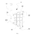
- FIG. 1 is a schematic view showing the structure of a wire dust filtering device in an embodiment of the present invention.
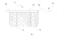
- FIG. 2 is a partial structural schematic view of a laundry treating apparatus in an embodiment of the present invention.
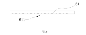
- FIG. 3 is a partial structural schematic view of a laundry treating apparatus in an embodiment of the present invention.
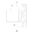
- FIG. 4 is a partial structural schematic view of a laundry treating apparatus in an embodiment of the present invention.
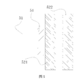
- Figure 5 is a partial structural view of a laundry treating apparatus in an embodiment of the present invention.
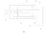
- Figure 6 is a partial structural view of a laundry treating apparatus in an embodiment of the present invention.
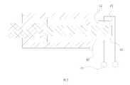
- Figure 7 is a partial structural view of a laundry treating apparatus in an embodiment of the present invention.
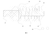
- Figure 8 is a partial structural view of a laundry treating apparatus in an embodiment of the present invention.
- Figure 9 is a partial structural schematic view of a laundry treating apparatus in an embodiment of the present invention.
- connection In the description of the present invention, it should be noted that the terms “installation”, “connected”, and “connected” are to be understood broadly, and may be fixed or detachable, for example, unless otherwise explicitly defined and defined. Connected, or integrally connected; can be mechanical or electrical; can be directly connected or indirectly connected through an intermediate medium. The specific meaning of the above terms in the present invention can be understood in a specific case by those skilled in the art.
- the present invention relates to a laundry treating apparatus comprising a wire filtering device; the control system adjusts a connection relationship between the wire filtering device and the laundry treating device mainly according to an operating condition of the laundry treating device.
- the control function for the installation and/or disassembly operation of the wire dust filter device is added during the operation, so that the device does not need to add a lock control switch that needs to be manually controlled during use, such as a buckle device in the prior art, the user
- the installation and/or disassembly operation carried out thereon is more convenient and quick, without any hindrance; further, the technical solution introduced by the invention makes it unnecessary to add any installation and/or disassembly operations on the basis of the original laundry treatment equipment.
- auxiliary components such as drawers and swing doors for placing the wire filtering device in the prior art, greatly simplifying the structural design of the device, avoiding the cooperation between the components, increasing the design burden and structure of the device. Burden and maintenance burden, and avoid the hidden dangers of adding additional auxiliary components to the installation stability of the chip filter device; further, the technical solution introduced by the present invention makes the device unnecessary to add additional to the installation and/or disassembly operation.
- Operation timing judging program the technical situation of the present invention, the operating condition of the device as an opportunity
- the monitoring of the power switch, the switch of the power source is used as a basis for judging whether the operating condition of the device changes; and the operation status of the device is determined, for example, by the data collected by the monitoring program of the air pump.
- the laundry treating device introduced by the invention also adds a vibration detecting device or a position detecting device to the device configuration, detects the vibration state or the position state of the wire filtering device during the operation of the device, and ensures that the control system can obtain the wire filtering device at any time. Vibration information or location information to provide data support for other applications.
- the wire filtering device is disposed on the laundry treating apparatus through a mounting portion.
- the mounting portion in this embodiment may be a separate component that is detachably connectable to at least one of the laundry treating device and the lint filtering device. Further, the mounting portion in this embodiment may be a set of interfitting components. The mounting portion is designed to achieve a connection between the chip filter device and the device while avoiding the burden on the structural design of the chip filter device.
- the mounting portion of the laundry treating apparatus in the embodiment includes a first member of the mounting portion provided on the chip filtering device and a second member of the mounting portion provided on the laundry treating device, the mounting portion The first piece of the mounting portion and the second piece of the mounting portion are engageable; the first piece of the mounting portion is a protrusion, and the second piece of the mounting portion is a groove that cooperates with the protrusion.
- one of the first member of the mounting portion or the second member of the mounting portion is a magnet
- the other is a material that can be attracted by the magnet, so that the two are connected by magnetic attraction during installation.
- the laundry treating apparatus of the present embodiment is different from the above embodiment in that the control system can adjust the connection relationship between the chip filtering device and the laundry treating device through the mounting portion.
- the control system can adjust the connection strength between the wire filtering device and the laundry treating device by adjusting the control condition when adjusting the connection relationship between the wire filtering device and the laundry treating device.
- the control condition may be current intensity
- the first piece of the mounting portion and/or the second part of the mounting portion includes an electromagnet.
- the first piece of the mounting portion disposed thereon is connected to the current conducting device of the laundry treating device, and when the device detects that the device starts to operate, the device passes the current conducting device.
- the through device transmits current to the first member of the mounting portion such that the first member of the mounting portion is magnetic, thereby causing the first member of the mounting portion to be attracted to the second member of the mounting portion.
- the current that is turned on on the current conducting device can be adjusted to change the bonding strength between the two.
- the laundry treating apparatus in this embodiment can adjust the magnetic force generated by the second piece of the mounting portion such that after the first piece of the mounting portion is mounted in place, the second piece of the mounting portion generates magnetism so that the two can be attracted together. .
- the laundry treating apparatus is different from the above embodiment in that the second member of the first member/mounting portion of the mounting portion itself has magnetic properties, and the magnetic poles on the opposite sides are the same. This allows a certain gap to be maintained between the two when the wire filter unit is installed.
- the first part of the mounting portion is provided on the laundry treating apparatus with a second member that can be coupled to the first member/mounting portion of the mounting portion and introduces a current thereon so that its magnetic properties disappear or become reverse magnetic. It can be firmly connected together with the second piece of the mounting portion by the action of magnetism.
- the control system cuts off the current, so that the first piece of the mounting portion and the second piece of the mounting portion are restored to the same polarity again, and the two are mutually exclusive, and a gap is generated between the two, so that the user can easily
- the chip filter is detached from the device.
- the number of the mounting portions in the embodiment is plural, and the plurality of the mounting portions are respectively disposed at different positions, and at least one of the plurality of mounting portions can adjust the wire filtering device and the laundry treating device. Connection relationship.
- the design enables the plurality of mounting portions to collectively function to mount and position the wire filtering device, thereby making the mounting effect of the wire filtering device more stable.
- the other mounting portions are configured to be engaged with each other, so that the bonding force generated by the mounting portion having the joint strength adjusting function is uniformly transmitted to all the wire filtering devices.
- connection function between the wire filtering device and the laundry treating device is realized by the mounting portion provided at multiple points, so that the control of the wire filtering device of the device is controlled by multiple points, which enables The device is more evenly and firmly connected from multiple locations to ensure that the position of the wire filter device is more stable when the device is in operation; and the device can obtain data generated by the position change of the wire filter device through system control to characterize the adhesion thereon.
- the amount of wire shavings is realized by the mounting portion provided at multiple points, so that the control of the wire filtering device of the device is controlled by multiple points, which enables The device is more evenly and firmly connected from multiple locations to ensure that the position of the wire filter device is more stable when the device is in operation; and the device can obtain data generated by the position change of the wire filter device through system control to characterize the adhesion thereon. The amount of wire shavings.
- the laundry treating apparatus of the present embodiment is different from the above embodiment in that the control system of the laundry treating apparatus issues a connection strength between the thread filtering device and the laundry treating apparatus when an instruction to start the laundry processing program is issued; It is preferable to strengthen the connection strength between the wire filtering device and the laundry treating apparatus by the mounting portion. It can be seen that the laundry treating apparatus in the embodiment does not start the program for adjusting the installation strength of the chip filtering device after the power is turned on, but the program for opening the bonding strength when the laundry treating device starts running the program. Make the adjustment of the device more suitable for the operation of the device.
- control system of the laundry treating device detects in real time whether the device starts to run the laundry processing program; if so, strengthens the connection strength between the first member of the mounting portion and the second member of the mounting portion;
- the mounting portion adjusts the control condition accordingly, thereby adjusting the connection strength between the wire filtering device and the laundry treating device;
- control system of the laundry treating apparatus detects in real time whether the apparatus starts to operate the laundry processing program; if so, increases the current intensity, thereby adjusting the connection strength between the wire filtering device and the laundry treating device.
- the laundry treating apparatus of the present embodiment is different from the above embodiment in that the laundry treating apparatus of the present embodiment includes a cleaning device for cleaning the thread filtering device.
- the swarf filtering device adjusts its connection relationship with the laundry treating device mainly according to the operating condition of the laundry treating device and/or the operating condition of the cleaning device.
- the second piece of the first part/mounting part of the mounting portion in the embodiment has magnetic properties, and the two pieces can be adsorbed together when installed, and the bonding strength is to some extent meet the impact requirement of the wire filtering. of.
- the bonding strength between the two is strengthened, so that even if the water flow/air flow impacts the wire filtering device, the wire filtering device is not detached, and the wire can be realized. Stable filtration of the chip filter unit.
- the second piece of the first piece/mounting portion of the mounting portion in the embodiment does not have magnetism itself, and can generate magnetism under the control of the device to achieve the connection.
- the installation strength of the wire filtering device is enhanced; when the device detects the start of the cleaning process of the wire filtering device, the installation strength of the wire filtering device is further enhanced.
- the wire filtering device is tightly integrated with the device, and the cleaning operation thereof does not affect the connection between the wire and the device, and the wire filtering device is kept in a stable position.
- the effect of cleaning is also better.
- the laundry treating apparatus in the embodiment may have an operation of alternately spraying a mixture of water spray, air jet, water spray and gas, water and gas during the cleaning operation of the thread filter device, according to the specificity of the thread filter device The situation is more appropriate for cleaning methods.
- the laundry treating apparatus of the present embodiment is different from the above embodiment in that the thread filtering device 1 of the present embodiment includes a structural portion 12 and a filtering portion 13 provided thereon, the structure
- the portion 12 is mainly used for the structural support
- the filter portion 13 is mainly used for realizing the filtering function.
- the structural portion 12 is provided with an operation portion 11 for realizing the installation and disassembly operation of the wire dust filtering device 1 by the user.
- the operation unit 11 is in the shape of a handle.
- the chip filter device 1 of the present embodiment has a plate shape as a whole, and one side of the operation portion 11 is provided so that the structure design does not affect the function of the wire filter function of the wire filter device itself.
- the mounting portion in this embodiment includes a first mounting portion, a second mounting portion, and a third mounting portion that are disposed in a distributed manner.
- the mounting portions are all disposed on the edges of the mechanism portion 12 such that the bonding and positioning of the mounting are achieved at a plurality of positions and does not affect the performance of the filtering function of the chip filtering device 1.
- the first pieces of the plurality of mounting portions in the embodiment are all disposed on and integrated with the wire dust filtering device 1.
- the plurality of mounting portions are arranged in an asymmetrical manner, so that the installed chip filter device remains stable under the impact of multiple angles.
- the size of the first mounting portion in this embodiment is smaller than the size of the second mounting portion and the third mounting portion.
- the first mounting portion, the second mounting portion, and the third mounting portion are all cylindrical.
- the first member 21 of the first mounting portion is disposed on the operating portion 11, the first member of the second mounting portion is disposed at the lowermost end of the structural portion 12, and the first member 23 of the third mounting portion is disposed at the most of the structural portion 12.
- the upper end (the upper and lower sides in this embodiment are the directions shown in Fig. 1, which are not actually used).
- first piece 23 of the third mounting portion and the first piece 22 of the second mounting portion are not in a straight line so that there is no installation error, preferably the first piece of the third mounting portion
- the size of the first piece 22 of the 23 and the second mounting portion is also different.
- the size of the first member of the first mounting portion is designed to be the smallest and is disposed on the operation portion 11, so that when the mounting/dismounting operation is performed, the position is first mounted/detached, and the bonding strength at that place The lowest and more user-friendly.
- the structural portion 12 in this embodiment has a two-layer structure, and the middle portion of the structural portion is a hollow structure, and a cavity is formed between the two layers, and the filter portion 13 is disposed in the cavity.
- the two-layer structure of the structural portion 12 is connected by the buckle 121; preferably, the buckle 121 is disposed around the structural portion 12 in a plurality of numbers.
- the cleaning device determines a cleaning angle and/or a cleaning force and/or a cleaning medium selection of the wire filtering device according to a detection result of the vibration detecting device.
- the cleaning medium includes a gas and/or a liquid.
- the cleaning device in this embodiment includes a first cleaning unit and a second cleaning unit, the cleaning medium of the first cleaning unit is a liquid, and the cleaning medium of the second cleaning unit is a gas.
- the spray medium is variously selected, and a plurality of kinds of mediums can be selectively used or alternately used.
- the operation of the spray liquid can be performed at the beginning of the operation of the online dust filter device.
- the cleaning device adjusts the spray medium to The gas makes it necessary to clean the chip filter device to meet the filtering function of the chip filter device itself, and to avoid the influence of the cleaning process on the cleaning function of the wire filter device.
- the cleaning device performs a cleaning operation with different cleaning devices for different cleaning media.
- the number of the first cleaning unit and/or the second cleaning unit is plural, and the two are spaced apart; then the different cleaning devices are responsible for different
- the medium spray simplifies the way the control system works, and, in a similar way, adds a third set of cleaning devices for spraying special cleaners.
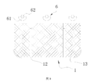
- the laundry treating apparatus is different from the above-described eighth embodiment in that the cleaning device 6 includes a shower portion 61 and a guiding portion 62 that penetrate inside, so that the shower portion A guide passage for guiding the fluid flow is formed inside the guide portion 61 and the guide portion 62; the cleaning device 6 further includes a control portion 63 for controlling the passage of the passage.
- the cleaning device in this embodiment is disposed above the wire filtering device; the spraying direction of the cleaning device is mainly downward.
- the cleaning device has a reasonable structure and a reasonable setting position, and is sprayed from above the wire filtering device, which is beneficial to fully utilizing the sprayed cleaning medium to better wash the wire dust filtering device;
- the shower portion, the guiding portion and the control portion in the embodiment are sequentially connected; the shower portion is a tubular structure, and a plurality of shower holes are provided on a side of the chip filter device.
- the plurality of shower holes are distributed along an extending direction of the shower portion.
- the control portion is capable of controlling the flow rate of the cleaning medium passing through the passage
- the cleaning device in this embodiment further includes an adjustment portion for controlling a spray direction of the shower portion such that the cleaning device is capable of adjusting a cleaning angle thereof to the chip filter device.
- the cleaning device is connected with the wire filtering device, so that when the spraying device cleans the wire filtering device, the relative positional relationship between the spraying device and the wire filtering device can be ensured, so that the spraying The medium sprayed by the shower device is accurately sprayed onto the wire filter device; further, the vibration generated by the wire filter device will cause the spray device to vibrate together, so that the vibrations of the two are synchronized, thereby ensuring the spray direction and the spray position.
- the adjusting portion is a motor for adjusting a rotation angle of the shower portion such that the shower portion is rotatable about an axial direction thereof or a direction parallel to the axial direction thereof, The spray angle of the shower is changed at the same time as the spray distance.
- the laundry treatment device introduced in the embodiment provides an adjustment portion on the shower device, so that the spray device can adjust the angle of the spray.
- the adjustment portion can drive the spray portion to rotate, thereby adjusting the spray angle;
- the rotation axis of the adjustment portion is in a parallel relationship with the axial direction of the shower portion, and the two are not the same straight line, so that the adjustment of the shower portion by the adjustment portion is not limited to the angle, but also The spray distance of the sprinkler filter device is adjusted to the spray portion.
- the vibration detecting device detects a vibration condition of the wire filtering device through a mounting portion.
- the vibration detecting device in this embodiment includes a switching member for controlling the operating state thereof.
- a switch member is added to the vibration detecting device so that the user can control whether the vibration detecting device is turned on.
- the vibration detecting device is turned on, the device can be adjusted according to the vibration condition of the wire filtering device during operation; if the switch member is closed, the device does not perform the detection of the vibration condition of the wire filtering device, so that the operation of the device is mainly based on the user's
- the setting rather than the actual operation of the device, allows the user to select the operational target of the device.
- the wire filtering device includes a structural portion 12 and a filtering portion 13 disposed thereon, the structural portion 12 is mainly used for structural support, and the filtering The section 13 is mainly used to implement the filtering function.
- the cleaning device in the embodiment is connected to the structural portion of the wire filtering device, and the shower portion extends in the same direction as the extending direction of the structural portion.
- the vibration detecting device is configured to detect a vibration condition of the wire dust filtering device when the cleaning device performs a cleaning operation; and when the detection result of the vibration detecting device meets a corresponding adjustment condition of the cleaning operation mode, the The cleaning device adjusts the corresponding cleaning operation.
- the cleaning mode of operation includes cleaning angles and/or cleaning forces and/or cleaning media. For example, in actual use, if the vibration of the wire filter device is obvious, the spray cleaning angle of the cleaning device is appropriately increased, and the cleaning medium is selected as water. Compared with air, the cleaning ability of water is stronger, the cleaning effect of more accumulated swarf is more obvious, and the wider cleaning range can achieve cleaning purpose to a greater extent.
- the lint attached to the lint filter device is gradually reduced.
- the cleaning medium is adjusted to a gas, so that the cleaning operation has an effect on the realization of the function of the lint filter device; further, The cleaning angle is correspondingly reduced to reduce the cleaning area, so that the part of the wire filtering device that has not been cleaned at this time strictly performs the filtering operation, and continues to clean the other parts, further ensuring the filtration function of the wire filtering device.
- the cleaning device is connected with the wire filtering device, so that when the spraying device cleans the wire filtering device, the relative positional relationship between the spraying device and the wire filtering device can be ensured, so that the spraying
- the medium sprayed by the shower device is accurately sprayed onto the wire filter device; further, the vibration generated by the wire filter device will cause the spray device to vibrate together, so that the vibrations of the two are synchronized, thereby ensuring the spray direction and the spray position. Effectiveness.
- the vibration detecting device of the laundry treating apparatus of the present embodiment includes a corresponding detecting first piece 51 and a detecting second piece 52; the detecting first piece 51 is for acquiring the wire dust filtering
- the detecting second member 52 can sense the change of the detecting first member 51 and generate a corresponding detection result.
- the detecting second member 52 can be disposed on the laundry treating device by maintaining a relatively stable positional relationship between the detecting second member 52 and the laundry treating device at the time of designing the device structure.
- the detecting first piece 51 is connected to the wire filtering device, and can generate a corresponding signal according to the vibration condition of the wire filtering device.
- the number of the vibration detecting devices in the embodiment is plural, and the plurality of vibration detecting devices respectively detect the vibration of different portions of the wire filtering device.
- the laundry treating apparatus in the embodiment realizes that the connection function of the wire filtering device and the laundry treating device is realized by the mounting portion provided at multiple points, so that the control of the wire filtering device of the device is controlled by multiple points, which enables Further, the vibration detecting device of the present invention detects the vibration condition of the wire filtering device through the mounting portion, that is, the vibration position of the wire dust filtering device and the device is detected by the mounting portion. To ensure the accuracy of the test results, and to accurately and timely characterize the vibration of the wire filter device.
- the vibration detecting device has a simple and reasonable structure, high sensitivity between components, and the vibration of the moving component (detecting the first component) reacts to the wire filtering device, and the stationary component (detecting the second component) is characterized.
- the vibration of the wire filter device ensures the accuracy and effectiveness of the test.
- the wire dust filtering device generates vibration
- the mounting portion vibrates together under the driving of the wire dust filtering device, thereby driving the detecting of the vibration of the first member 51, and changing the relative positional relationship between the detecting first member 51 and the detecting second member 52,
- the person continuously generates a signal capable of characterizing the position change, and achieves the purpose of detecting the vibration detection of the wire dust filtering device.
- the second detecting part of the fixed vibration detecting device comprises a plurality of levels of detecting the second piece, and each level detecting the second piece respectively detects vibrations of different intensities and respectively generates corresponding signals.
- the detecting second member in this embodiment includes a first-level detecting second member 521 and a second-level detecting second member 522 respectively disposed opposite to the detecting first member.
- the vibration detecting device in the present embodiment is for detecting a vibration condition when the laundry treating device executes the laundry treating program, and the vibration detecting device detects that there is an abnormality in the vibration condition of the wire filtering device, and the laundry treating device adjusts the corresponding device The operating state, in turn, adjusts the vibration of the wire filter device.
- the vibration detecting device comprises a multi-stage detecting mechanism, and corresponding data is generated for the vibration degree of the wire dust filtering device, so that the device can perform corresponding processing.
- the vibration detecting device with a lower detection level when the vibration detecting device with a lower detection level generates a corresponding signal, the device continues to operate and allows the corresponding device to continue to improve the operating efficiency; when the vibration detecting device with a higher detection level generates a corresponding signal, the device The corresponding device is prohibited from continuing to improve the operating efficiency; when the vibration detecting device with a higher detection level generates a corresponding signal, the device lowers the corresponding device to continue to improve the operating efficiency.
- the detecting first part in the embodiment comprises a magnet; the detecting second part is a reed switch; the distance between the different levels of detecting the second piece and the corresponding detecting first piece is different.
- the detecting the first piece in the embodiment comprises a magnet; the detecting the second piece is a reed switch; the different levels of detecting the second piece are different in magnetic sensing capability.
- the laundry treating apparatus differs from the above embodiment in that the control system of the apparatus obtains the cleanliness of the swarf filtering device according to the detection result of the vibration detecting device and/or the operating state of the corresponding device; The system displays the cleanliness of the lint filter device to the user after the laundry treatment device completes the laundry treatment operation.
- the cleanliness of the lint filter device is obtained based on the detection result of the vibration detecting device and/or the operating state of the corresponding device, and when the cleanliness reaches a certain level, the system begins to perform an automatic cleaning operation of the lint filter device.
- the cleanliness of the swarf filtering device is obtained according to the detection result of the vibration detecting device and/or the working state of the cleaning device, and the cleanliness is fed back to the user, so that the user can filter the swarf
- the cleaning condition of the device has an intuitive feeling, ensuring the user's working condition of the wire filter device and the working condition of the cleaning device.
- the cleaning device cleans the cleaning medium by spraying the cleaning medium to the thread filtering device.
- the position detecting device is configured to detect a relative position state between the wire filtering device and the laundry treating device, and generate a corresponding signal for adjusting the operation of the cleaning device;
- the position detecting device includes a detecting communication member 41, a first detecting point 42, and a controller 43 that cooperate with each other; the detecting communication member 41 acquires a relative positional relationship between the chip filtering device and the laundry treating device, and mainly Taking this as a basis for controlling the communication relationship between the first detection point 42 and the controller 43 to generate a corresponding signal, thereby realizing the detection of the position state of the chip filtering device, the detecting communication member being disposed at the mounting portion A piece is connected to the second piece of the mounting portion and is movable in the direction of the second piece of the mounting portion by the pushing of the first piece of the mounting portion, thereby turning on the connection between the detecting point and the controller.
- the detecting communication member 41 is made of a material that allows current to pass therethrough.
- the circuit formed by the first detecting point 42 and the controller 43 is communicated to generate a signal.
- the first piece 31 of the mounting portion is moved to the left side to the position shown as 2, it indicates that the wire filtering device is away from the device, so that the detecting communication member 41 is also moved to the left side of FIG. 7, thereby turning off the first detection.
- the circuit formed by point 42 and controller 43 produces a signal.
- the relative position between the first detection point 42 and the controller 43 in the present embodiment is fixed, and the connection of the connection relationship between the two is controlled by the detection communication member 41.
- the number of detection points of the position detecting device in the embodiment is multiple, and the plurality of detection points respectively correspond to different detection values, and different detection signals are generated when different detection points are connected to the controller.
- the detecting communication member connects the corresponding detecting point to the controller according to a relative positional relationship between the wire filtering device and the laundry treating device. Further, the detecting communication member is connected to the chip filtering device.
- the detection point in this embodiment includes at least a first detection point 42 and a second detection point 45. When detecting that the moving distance of the connecting member is different, the connection situation of the plurality of detecting points is different, thereby generating different signals to characterize the wire filtering device. The amount of change in different positions.
- the first detection point 42 when the first detection point 42 is turned "on", it indicates that the chip filtering device begins the filtering operation.
- the second detection point 45 when the second detection point 45 is turned on, it indicates that there are already many swarf attached to the swarf filter device, and the swarf filter device should be cleaned.
- the cleaning device is activated and the cleaning of the thread filter is started.
- the swarf on the swarf filter device is gradually removed, and the second detection point 45 is broken, indicating that the swarf filter device has recovered the cleaning ability.
- the cleaning device stops cleaning the thread filter device.
- the position detecting device of the embodiment includes a resetting member for returning the detecting communication member to the initial position, thereby disconnecting the detecting point from the controller, and generating a corresponding signal, so that the cleaning device is adjusted and cleaned.
- the cleaning means includes a cleaning angle and/or a cleaning force and/or a choice of cleaning medium.
- a resetting device is provided, so that the position detecting device can be reset after the detection is completed or after the laundry treating device stops working, and the precision of the next detection is ensured, so that the wire filtering device is reset, thereby making Users can easily remove it.
- the cleaning method in this embodiment includes a cleaning angle and/or a cleaning force and/or a selection of a cleaning medium including a gas and/or a liquid.
- the spray media is variously selected, and a plurality of media can be selectively used or alternately used.
- the operation of the spray liquid can be performed on the initial stage of the online dust filter device, and when the position state change degree of the wire dust filter device is alleviated, and the position state change amount is reduced to a certain value, the cleaning device will spray again.
- the leaching medium is adjusted to a gas, so that the cleaning of the swarf filtering device is satisfied to meet the filtering function of the swarf filtering device itself, and the cleaning process is prevented from affecting the cleaning function of the swarf filtering device.
- the position detecting device in this embodiment detects the positional state of the wire filtering device by detecting a change in position of the mounting portion.
- a position detecting device is coupled to the mounting portion.
- the mounting portion is rationally designed, and the mounting portion includes a plurality of mutually cooperating portions, so that it can generate a corresponding signal according to the position of the wire filtering device, and can detect the wire filtering device. Whether the position change is generated or not, the position change amount of the chip filter device can be detected, and the qualitative and quantitative detection can be realized, so that the device can adjust to different degrees according to different position offsets.
- the laundry treating apparatus of the present embodiment is different from the above embodiment in that the number of the cleaning devices 6 is plural, and the plurality of cleaning devices 6 are opposed to the wire filtering device 1 The location is different. At least one of the plurality of cleaning devices 6 is disposed above the lint filter device 1.
- the cleaning device includes a guide portion 62 that guides the cleaning medium and a shower portion 61 that sprays the cleaning medium. At least two of the plurality of cleaning devices determine that the timing of starting execution and/or adjusting and/or ending the cleaning operation is different according to the detection result of the position detecting device, so that at least two of the plurality of cleaning devices are executed The cleaning operation is not synchronized.
- the order of opening of the plurality of cleaning devices can be adjusted. Due to the different cleaning ranges of each cleaning device, cleaning of different regions of the chip filtering device at different times is achieved. Therefore, at the time of cleaning the chip filtering device, at least one portion of the wire filtering device is in a state that does not need to be cleaned, and the wire filtering function of the portion is complete, and the filtering effect of the wire filtering device can be ensured even if This part can also fully exert the filtering effect when cleaning in other areas.
- the laundry treating apparatus of the present embodiment is different from the above embodiment in that the control system of the apparatus obtains the cleanliness of the swarf filtering device based on the detection result of the position detecting device and/or the operating state of the cleaning device.
- the control system displays the cleanliness of the lint filter device to the user after the laundry treatment device completes the laundry treatment operation.
- the cleanliness of the swarf filtering device is obtained according to the detection result of the vibration detecting device and/or the working state of the cleaning device, and the cleanliness is fed back to the user, so that the user can filter the swarf
- the cleaning condition of the device has an intuitive feeling, ensuring the user's working condition of the wire filter device and the working condition of the cleaning device.
Landscapes
- Engineering & Computer Science (AREA)
- Textile Engineering (AREA)
- Chemical & Material Sciences (AREA)
- Chemical Kinetics & Catalysis (AREA)
- Physics & Mathematics (AREA)
- General Physics & Mathematics (AREA)
- Control Of Washing Machine And Dryer (AREA)
- Detail Structures Of Washing Machines And Dryers (AREA)
- Accessory Of Washing/Drying Machine, Commercial Washing/Drying Machine, Other Washing/Drying Machine (AREA)
Abstract
一种衣物处理设备,包括线屑过滤装置(1);控制系统主要根据衣物处理设备的运行状况调整所述线屑过滤装置(1)与衣物处理设备的连接关系;还包括用于对所述线屑过滤装置(1)进行清洁的清洁装置(6),所述控制系统还可以主要根据衣物处理设备的运行状况和/或清洁装置(6)的运行状况调整线屑过滤装置(1)与衣物处理设备的连接关系。另外,在设备构成上还增加了振动检测装置或者位置检测装置,在设备运行过程中检测线屑过滤装置(1)的振动状态或位置状态,保证控制系统能够时刻获得线屑过滤装置(1)的振动信息或位置信息,为其它应用提供数据支持,所述衣物处理设备使得用户对线屑过滤装置(1)的安装、拆卸及线屑清洗状况在控制系统的配合下更加灵活,更加方便。
Description
本发明属于衣物处理领域,具体地说,涉及一种衣物处理设备。
现有技术中的衣物处理设备,特别是干衣设备,通常设有用于去除设备内部风路中的线屑的装置。若无此装置,则线屑随空气流动直接附着在冷凝器上,影响冷凝器发挥冷凝效果,并且附着在冷凝器的线屑也不易收集,为用户的使用带来不便。因此,线屑过滤装置的设置是十分必要的。而线屑过滤装置拦截线屑后必然面临将附着其上的线屑去除的问题,将线屑过滤装置从衣物处理设备上取下在对其进行清洁是最为直接的方法,而安装线屑过滤装置和拆除线屑过滤装置是对立的两个操作,如何实现两种操作之间的协调,使之不会互相影响,同时保证两者各自的执行效果,成为亟待解决的问题。为解决此问题,现有技术中存在为线屑过滤装置单独设置安装翻斗,安装翻斗通过旋转轴可卡扣的配合改变线屑过滤装置的延伸方向,使得用户能够将其取出。但是,安装翻斗本身为一活动件,其自身的安装、使用就面临翻转是否到位、定位是否牢固、受到震动是否会松懈的问题,可见,此种解决问题的方式将会带来其他方面的问题,存在影响线屑过滤装置使用性能的隐患。并且,衣物处理设备使用过程中通过线屑过滤装置的气流量大小不同,对线屑过滤装置的冲击作用不同,使得线屑过滤装置发生松脱的可能性不同,如何对此种情况适当的处理,或者进一步地将对此种情况处理的手段、程度进行更加深入的利用,用于表征其他方面的衣物处理情况,则对衣物处理设备使用性能的发挥带来更深层次的挑战。
有鉴于此特提出本发明。
发明内容
本发明要解决的技术问题在于克服现有技术的不足,提供一种衣物处理设备,通过对线屑过滤装置的结构安装原理、安装方式以及与之配合的控制系统的设计,使得衣物处理设备能够根据设备的运行情况对线屑过滤装置与设备的结合方式结合强度做出调整,增加了线屑过滤装置的安装、拆卸控制方式,使得用户对线屑过滤装置的安装、拆卸在控制系统的配合下更加灵活,更加方便。
为解决上述技术问题,本发明采用技术方案的基本构思是:
一种衣物处理设备,包括线屑过滤装置;控制系统主要根据衣物处理设备的运行状况调整所述线屑过滤装置与衣物处理设备的连接关系。
本发明进一步设置为:所述衣物处理设备包括用于对所述线屑过滤装置进行清洁的清洁装置;
优选地,所述控制系统主要根据衣物处理设备的运行状况和/或清洁装置的运行状况调整线屑过滤装置与衣物处理设备的连接关系。
本发明进一步设置为:所述清洁装置在设备执行衣物处理程序时对所述线屑过滤装置进行清洁;
优选地,所述清洁装置对线屑过滤装置进行清洁时对线屑过滤装置进行喷水和/或喷气;
进一步优选地,所述清洁装置包括第一清洁单元和第二清洁单元,所述第一清洁单元的清洁介质为液体,所述第二清洁单元的清洁介质为气体。
本发明进一步设置为:所述清洁装置包括在内部贯通的喷淋部和引导部,使得喷淋部和引导部内部形成用于导通流体流动的通道;所述清洁装置还包括用于控制所述通道通断的控制部;
优选地,所述喷淋部、引导部和控制部依次连接;
进一步优选地,所述清洁装置设置于所述线屑过滤装置的上方;
更进一步优选地,所述喷淋部为管状结构,其一侧设有多个喷淋孔;
更进一步优选地,所述多个喷淋孔沿所述喷淋部的延伸方向分布;
更进一步优选地,所述控制部能够控制通过所述通道中的清洁介质的流量大小。
本发明进一步设置为:所述清洁装置还包括用于控制所述喷淋部的喷淋方向的调整部,使得所述清洁装置能够调整其对所述线屑过滤装置的清洁角度;
优选地,所述调整部能够调整所述喷淋部的旋转角度,使得所述喷淋部能够绕其轴向/与其轴向平行的方向旋转,在改变所述喷淋部的喷淋角度的同时改变喷淋距离;
进一步优选地,所述调整部设置于所述喷淋部的一端;
更进一步优选地,所述调整部设置于所述喷淋部与所述引导部相对的另一端;
优选地,所述调整部为电机。
本发明进一步设置为:所述线屑过滤装置包括结构部以及设置于其上的过滤部,所述结构部主要实现结构支撑,所述过滤部主要实现过滤功能;
优选地,所述清洁装置与所述线屑过滤装置连接;
进一步优选地,所述喷淋部与所述结构部连接;
进一步优选地,所述喷淋部的延伸方向与所述结构部的延伸方向相同;
进一步优选地,所述结构部上设有操作部,用于实现用户对线屑过滤装置的安装、拆卸操作;
更进一步优选地,所述操作部为提手状。
本发明进一步设置为:所述线屑过滤装置通过安装部设置于所述衣物处理设备上;
优选地,所述安装部包括设置于所述线屑过滤装置上的第一件和设置于衣物处理设备上的第二件,所述第一件和第二件能够配合连接;
进一步优选地,所述第一件和所述第二件之间凹凸配合连接。
本发明进一步设置为:控制系统主要通过安装部调整所述线屑过滤装置与衣物处理设备的连接关系;
优选地,所述安装部主要通过控制条件的改变进而调整线屑过滤装置与衣物处理设备之间的连接强度;
进一步优选地,所述控制条件包括电流强度,所述第一件和/或第二件包括电磁铁;
优选地,所述安装部的数量为至少两个;
进一步优选地,多个所述安装部分别设置于不同位置上;
更进一步优选地,多个所述安装部中至少一个能够调整线屑过滤装置与衣物处理设备的连接关系。
本发明进一步设置为:衣物处理设备的控制系统发出开始运行衣物处理程序的指令时,加强所述线屑 过滤装置与衣物处理设备之间的连接强度;优选通过所述安装部加强所述线屑过滤装置与衣物处理设备之间的连接强度;
优选地,衣物处理设备的控制系统发出开始运行衣物处理程序的指令时,加强所述第一件和第二件之间的连接强度;
进一步地优选地,衣物处理设备的控制系统发出开始运行衣物处理程序的指令时,安装部对所述控制条件进行相应的调整,进而调整线屑过滤装置与衣物处理设备之间的连接强度;
更进一步优选地,衣物处理设备的控制系统发出开始运行衣物处理程序的指令时,增加所述电流强度,进而调整线屑过滤装置与衣物处理设备之间的连接强度。
更进一步优选地,衣物处理设备的控制系统发出停止运行衣物处理程序的指令时,减弱所述线屑过滤装置与衣物处理设备之间的连接强度;
更进一步优选地,衣物处理设备的控制系统发出停止运行衣物处理程序的指令时,减弱/归零所述电流强度,进而调整线屑过滤装置与衣物处理设备之间的连接强度。
本发明进一步设置为:衣物处理设备的控制系统发出执行对线屑过滤装置进行清洁的程序的指令时,加强所述线屑过滤装置与衣物处理设备之间的连接强度;
优选地,衣物处理设备的控制系统发出执行对线屑过滤装置进行清洁的程序的指令时,加强所述第一件和第二件之间的连接强度;
进一步优选地,衣物处理设备的控制系统发出执行对线屑过滤装置进行清洁的程序的指令时,安装部对所述控制条件进行相应的调整,进而调整线屑过滤装置与衣物处理设备之间的连接强度;
进一步优选地,衣物处理设备的控制系统发出执行对线屑过滤装置进行清洁的程序的指令时,增加电流强度,进而调整线屑过滤装置与衣物处理设备之间的连接强度。
本发明进一步设置为:所述设备的控制系统根据对所述线屑过滤装置的位置调整情况获得所述线屑过滤装置的清洁度;
优选地,所述控制系统在衣物处理设备完成衣物处理操作后将所述线屑过滤装置的清洁度展示给用户。
本发明进一步设置为:衣物处理设备包括用于检测设备进气湿度的湿度检测装置;优选地,当所述湿度检测装置检测到进气湿度超过相应的阈值时,则控制系统调整所述线屑过滤装置与衣物处理设备的连接关系;
进一步优选地,当所述湿度检测装置检测到进气湿度超过相应的阈值时,则控制系统加强所述线屑过滤装置与衣物处理设备的连接关系。
本发明提供一种通过对线屑过滤装置的结构安装原理、安装方式以及与之配合的控制系统的设计,使得衣物处理设备能够根据线屑过滤装置的振动情况采取相应的、适当的清洁方式,保证清洁效率、清洁效果的同时避免清洁操作对线屑过滤装置的功能的实现造成影响。
本发明所述的衣物处理设备还包括用于检测衣物处理设备运行过程中所述线屑过滤装置振动情况的振动检测装置,所述清洁装置根据所述振动检测装置的检测结果调整对所述线屑过滤装置的清洁操作方式;
优选地,所述清洁装置根据所述振动检测装置的检测结果确定对所述线屑过滤装置的清洁角度和/或 清洁力度和/或清洁介质的选择。
本发明通过对线屑过滤装置的结构安装原理、安装方式以及与之配合的控制系统的设计,使得衣物处理设备能够根据线屑过滤装置的振动情况采取相应的、适当的清洁方式,保证清洁效率、清洁效果的同时避免清洁操作对线屑过滤装置的功能的实现造成影响。
本发明进一步设置为:所述线屑过滤装置通过安装部设置于所述衣物处理设备上;
优选地,所述振动检测装置通过安装部检测所述线屑过滤装置的振动情况;
所述振动检测装置包括用于控制其工作状态的开关件。
本发明进一步设置为:衣物处理设备在执行清洁操作时,所述振动检测装置检测所述线屑过滤装置的振动情况;所述振动检测装置的检测结果满足清洁操作方式的相应的调整条件时,则所述清洁装置调整相应的清洁操作方式;
优选地,所述清洁操作方式包括清洁角度和/或清洁力度和/或清洁介质。
本发明进一步设置为:所述振动检测装置包括对应设置的检测第一件和检测第二件;所述检测第一件获取所述线屑过滤装置的振动情况,所述检测第二件能够感应所述检测第一件的变化,并生成相应的检测结果;
优选地,所述检测第一件设置于所述线屑过滤装置上,能够根据线屑过滤装置的振动情况产生相应的变化;
进一步优选地,所述振动检测装置的数量为至少两个,不同振动检测装置分别检测所述线屑过滤装置不同部位的振动情况。
本发明进一步设置为:所述振动检测装置的检测第二件包括至少两个级别的检测第二件,每级检测第二件分别检测不同强度的振动情况,并分别生成相应的信号;
优选地,所述检测第一件包括磁铁;所述检测第二件为干簧管;不同级别的检测第二件和与之对应的检测第一件之间的距离不同;
进一步优选地,所述检测第一件包括磁铁;所述检测第二件为干簧管;不同级别的检测第二件对磁性的感应能力不同。
本发明提供一种通过对线屑过滤装置的结构安装原理、安装方式以及与之配合的控制系统的设计,使得衣物处理设备能够根据线屑过滤装置的位置变化情况对清洁时机进行判断,保证线屑过滤装置的使用效果的同时,采集线屑过滤装置产生的数据加以利用。
本发明所述的衣物处理设备还包括用于检测衣物处理设备运行过程中所述线屑过滤装置的位置状态的位置检测装置,所述清洁装置根据所述位置检测装置的检测结果确定开始执行清洁操作的时机;
优选地,所述清洁装置根据所述位置检测装置的检测结果确定调整清洁方式和/或结束清洁操作的时机。
本发明进一步设置为:所述位置检测装置检测所述线屑过滤装置与所述衣物处理设备之间相对位置状态,并生成相应的信号;控制系统根据所述信号调整清洁装置的运行;
优选地,所述位置检测装置包括相互配合的检测连通件、检测点、控制器;所述检测连通件获取所述线屑过滤装置与衣物处理设备之间的相对位置关系,并主要以此为据控制检测点与控制器之间的连通关 系,以产生相应的信号,进而实现对线屑过滤装置的位置状态的检测;
进一步优选地,所述检测点与控制器之间相对位置固定,并由所述检测连通件控制两者之间连接的通断;
更进一步优选地,所述检测点的数量为至少两个,不同所述检测点分别对应不同的检测值,当不同的检测点与控制器连接时产生不同的检测信号;所述检测连通件根据线屑过滤装置与衣物处理设备之间的相对位置关系将相应的检测点与控制器连接;
更进一步优选地,所述检测连通件与所述线屑过滤装置连接。
本发明进一步设置为:所述位置检测装置包括用于使检测连通件恢复位置复位件,进而使得检测点与控制器之间断开,并产生相应的信号,使得清洁装置调整清洁方式/结束清洁操作;
优选地,所述清洁方式包括清洁角度和/或清洁力度和/或清洁介质的选择;
优选的,所述恢复位置包括恢复初始位置。
本发明进一步设置为:所述线屑过滤装置通过安装部设置于所述衣物处理设备上;
进一步优选地,所述安装部的数量为至少两个;
更进一步优选地,不同的所述安装部分别设置于不同位置上。
本发明进一步设置为:所述位置检测装置主要通过检测所述安装部的位置变化检测所述线屑过滤装置的位置状态;
优选地,所述位置检测装置与所述安装部连接;
进一步优选地,所述检测连通件与所述安装部连接。
本发明进一步设置为:所述清洁装置的数量为至少两个,每个所述清洁装置相对于所述线屑过滤装置的位置不同;
优选地,所述清洁装置中至少一个设置于所述线屑过滤装置的上方;
进一步地,所述清洁装置中至少有两个根据所述位置检测装置的检测结果确定开始执行和/或调整和/或结束清洁操作的时机和/或方式不同,使得所述清洁装置中至少有两个执行的清洁操作不同步;
优选地,所述设备的控制系统根据位置检测装置的检测结果和/或清洁装置的工作状态获得所述线屑过滤装置的清洁度;
优选地,所述控制系统在衣物处理设备完成衣物处理操作后将所述线屑过滤装置的清洁度展示给用户。
本发明进一步设置为:衣物处理设备包括用于检测设备进气湿度的湿度检测装置;优选地,当所述湿度检测装置检测到进气湿度超过相应的阈值时,则控制系统降低判断清洁装置开启时机的阈值;
优选地,当所述湿度检测装置检测到进气湿度超过相应的阈值时,则控制系统提高判断清洁装置停止时机的阈值;
通过上述设计,使得清洁装置对线屑过滤装置的感应更加敏感,当线屑过滤装置存在线屑积累的隐患时,就对其进行清理,避免潮湿空气带来的湿度较大的线屑附着在线屑过滤装置上时间久了不易去除。该设计一方面延长了清洁线屑过滤装置的清洁时间,另一方面提高了针对线屑过滤装置的清洁频率,有利于 在湿度较大的条件下保持线屑过滤装置上附着的线屑能够及时清除。
本发明进一步设置为:当所述湿度检测装置检测到进气湿度超过相应的阈值时,则在每次清洁装置执行完对所述线屑过滤装置的清洁操作之后,再对所述线屑过滤装置喷射气体并保持一定时间。
通过上述设计,使得清洁装置在对所述线屑过滤装置上附着的线屑完成清理后对线屑过滤装置进行干燥,使得其上不会因为空气湿度的增加而使得后续附着的线屑不易于清理。
本发明进一步设置为:所述衣物处理设备包括洗衣机/干衣机/洗干一体机。
采用上述技术方案后,本发明与现有技术相比具有以下有益效果。
1、通过本发明介绍的衣物处理设备,在线屑过滤装置的安装和/或拆卸操作的实施过程中增加了针对其的控制功能,使得设备在使用过程中无需增加需人为控制的锁定控制开关,例如现有技术中的卡扣装置,用户对其实施的安装和/或拆卸操作更加方便快捷,不会受到任何阻碍。
2、通过本发明介绍的衣物处理设备,在原有的衣物处理设备的基础上无需增加任何为配合安装和/或拆卸操作以及定位的辅助部件,例如现有技术中的用于放置线屑过滤装置的抽屉、转门等,极大程度的简化了设备的结构设计,避免部件之间的配合增加设备的设计负担、结构负担及维护负担,并且避免了增加额外的辅助部件为线屑过滤装置的安装稳定性带来的隐患。
3、通过本发明介绍的衣物处理设备,使得设备无需对安装和/或拆卸操作增加额外的操作时机判断程序,本发明的技术方案以设备的运行状况作为时机判断的依据,毕竟设备运行过程中对线屑过滤装置实施安装和/或拆卸操作时较为不便的,则将设备是否运行/相应程序是否运行作为时机判断的依据,仅需借用设备的原有监视程序即可完成,例如对电源开关的监视、对程序运行(例如干衣程序、洗涤程序、漂洗程序)进行控制的控制系统,通过电源的开关、程序运行的启动指令作为设备运行状况是否发生变化的判断依据;再例如通过对吹风单元的监视程序采集的数据判断设备的运行状况。
4、通过本发明介绍的衣物处理设备,实现线屑过滤装置与衣物处理设备的连接功能通过多点设置的安装部实现,使得设备对线屑过滤装置的控制为多点的控制,能够使得其从多个位置更加均匀、牢固的与设备连接,保证设备工作时线屑过滤装置的位置更加稳定;并且,设备通过系统控制能够获得线屑过滤装置的位置变化产生的数据,以表征其上附着的线屑的量。
5、通过本发明介绍的衣物处理设备,还设置有清洁装置,设备运行过程中,线屑过滤装置与设备结合紧密,该过程对其进行清洁操作不会影响其与设备之间的连接,并且线屑过滤装置保持位置稳定的状态下对其进行清洁的效果也更好;清洁装置结构合理、设置位置合理,从线屑过滤装置的上方对其进行喷淋,有利于充分利用喷淋出的清洁介质更好的冲刷线屑过滤装置。
6、通过本发明介绍的衣物处理设备,喷淋介质选择多样,并且,多种介质可以有选择的使用或者交替使用。例如,可在线屑过滤装置开始工作的初期对其执行喷淋液体的操作,当线屑过滤装置的振动情况有所缓解,并且振动强度降低到一定值时,清洁装置再将喷淋介质调整为气体,使得对线屑过滤装置的清洁以满足线屑过滤装置自身的过滤功能为前提,避免清洁过程对线屑过滤装置的清洁功能造成影响。
7、通过本发明介绍的衣物处理设备,能够在对线屑过滤装置执行清洁操作时加强线屑过滤装置与设备之间的连接,进一步保证清洁效果的同时,通过线屑过滤装置与设备之间的连接程度、连接情况表征线屑过滤装置的清洁效果。
8、通过本发明介绍的衣物处理设备,对线屑过滤装置的结构进行改进,增加提手的设计,再配合设备对线屑过滤装置设计的安装位置,使得用户仅通过简单的提拉操作就能将线屑过滤装置从设备中取出, 同理,用户仅需通过简单的推入操作就能将线屑过滤装置放入设备中,一方面简化了设备的整机结构,另一方面简化了线屑过滤装置的结构设计还能不影响线屑过滤装置的使用性能,再一方面线屑过滤装置无需抽屉等辅助结构就实现稳定、牢固、到位的安装。
9、通过本发明介绍的衣物处理设备,将清洁装置与线屑过滤装置连接,使得喷淋装置对线屑过滤装置进行清洁时,能够保证喷淋装置与线屑过滤装置的相对位置关系,使得喷淋装置喷出的介质准确的喷到线屑过滤装置上;进一步地,线屑过滤装置产生的位置变化时会带动喷淋装置一起产生位置,使得两者位置同步,进而保证喷淋方向、喷淋位置的有效性;此技术方案可通过将所述喷淋装置的介质疏导部件设为柔软的、弹性的结构即可,例如,设置为橡胶管。
10、通过本发明介绍的衣物处理设备,将清洁装置针对不同的清洁介质采用不同的清洁装置执行清洁操作,优选地,第一清洁单元和/或第二清洁单元的数量为多个,两者间隔设置;则不同的清洁装置负责不同的介质喷淋,能够简化控制系统的工作方式,并且,还可以以此类推,增加第三套清洁装置,用于喷淋特殊的清洁剂。
11、通过本发明介绍的衣物处理设备,在喷淋装置上设置调整部,使得喷淋装置能够实现对喷淋的角度的调整,优选调整部能够带动喷淋部旋转,进而调整喷淋角度;进一步优选地,调整部的旋转轴向为与所述喷淋部的轴向为平行的关系,并且两者并非为同一条直线,使得调整部对喷淋部的调整不仅仅局限于角度,还能够对喷淋部对线屑过滤装置的喷淋距离进行调整。
12、通过本发明介绍的衣物处理设备,在设备构成上增加了振动检测装置或者位置检测装置,在设备运行过程中检测线屑过滤装置的振动状态或位置状态,保证控制系统能够时刻获得线屑过滤装置的振动信息或位置信息,为其它应用提供数据支持。
13、通过本发明介绍的衣物处理设备,在设备构成上增加了振动检测装置,在设备运行时实时监测线屑过滤装置的振动状态,保证控制系统能够时刻获得线屑过滤装置的振动信息,为其它应用提供数据支持,以此判断清洁装置工作的最佳工作方式。线屑过滤装置由于其上附着的线屑的量、附着情况不同,其振动情况会发生相应的变化。当线屑过滤装置的振动情况满足一定条件时,则可以判定其上积累的线屑过多,应当执行清洁操作,进一步地,控制系统控制清洁装置开始对线屑过滤装置进行清洁。并且,随着线屑清理的进行,线屑过滤装置上附着的线屑的量越来越少,对其进行的清洁的方式也应进一步的进行调整,保证清洁操作方式满足各个阶段的清洁操作,针对各个阶级的清洁操作的单独对待,充分考虑其特殊情况的同时,避免清洁操作对线屑过滤装置的过滤功能的实现造成影响;可见,根据线屑过滤装置的振动情况判断其上附着的线屑的量、线屑的附着情况,能够实现对清洁操作的方式进行判断,使得清洁装置的工作依据为线屑过滤装置的具体情况,而不是现有技术中的“连续使用时间”等抽象的概念,进一步保证线屑过滤装置的清洁的及时性,并且避免频繁的清洁操作影响线屑过滤装置的使用或增加系统的控制负担。
14、通过本发明介绍的衣物处理设备,在设备构成上增加了位置检测装置,在设备运行时实时监测线屑过滤装置的位置状态,保证控制系统能够时刻获得线屑过滤装置的位置信息,为其它应用提供数据支持,以此判断清洁装置开始工作的时机。线屑过滤装置由于其上附着的线屑的量、附着情况不同,其位置情况会发生相应的变化,或者,可在线屑过滤装置和/或安装部的结构设计上预设用于给线屑过滤装置的位置变化提供一定余量的部件,使得线屑过滤装置能够根据其上附着的线屑的量、线屑分布的位置产生相应的位置变化,进而表征线屑的附着情况。当线屑过滤装置的位置状态满足一定条件时,则可以判定其上积累的线屑过多,应当执行清洁操作。进一步地,控制系统控制清洁装置开始对线屑过滤装置进行清洁。可见,根据线屑过滤装置的位置状态判断其上附着的线屑的量、线屑的附着情况,能够实现对清洁操作的时机的 判断,使得清洁装置的工作依据为线屑过滤装置的具体情况,而不是现有技术中的“连续使用时间”等抽象的概念,进一步保证线屑过滤装置的清洁的及时性,并且避免频繁的清洁操作影响线屑过滤装置的使用或增加系统的控制负担。
15、通过本发明介绍的衣物处理设备,根据振动检测装置或位置检测装置的检测结果和/或清洁装置的工作状态获得所述线屑过滤装置的清洁度,并将清洁度反馈给用户,使得用户能够对线屑过滤装置的清洁情况具有直观的感受,保证用户对线屑过滤装置的工作情况以及清洁装置的工作情况掌握。
16、通过本发明介绍的衣物处理设备,能够实现对线屑过滤装置与设备之间连接强度的调整,该技术方案适用范围广泛,可应用于洗衣机、干衣机、洗干一体机等衣物处理设备。由于洗衣机在执行衣物处理程序时,水流或吹风对线屑过滤装置的冲击作用较大,容易使线屑过滤装置松动脱落,本发明中的技术方案则完全解决了该技术问题。
下面结合附图对本发明的具体实施方式作进一步详细的描述。
附图作为本发明的一部分,用来提供对本发明的进一步的理解,本发明的示意性实施例及其说明用于解释本发明,但不构成对本发明的不当限定。显然,下面描述中的附图仅仅是一些实施例,对于本领域普通技术人员来说,在不付出创造性劳动的前提下,还可以根据这些附图获得其他附图。在附图中:
图1是本发明一个实施例中的线屑过滤装置的结构示意图。
图2是本发明一个实施例中的衣物处理设备部分结构示意图;
图3是本发明一个实施例中的衣物处理设备部分结构示意图;
图4是本发明一个实施例中的衣物处理设备部分结构示意图;
图5是本发明一个实施例中的衣物处理设备部分结构示意图;
图6是本发明一个实施例中的衣物处理设备部分结构示意图;
图7是本发明一个实施例中的衣物处理设备部分结构示意图;
图8是本发明一个实施例中的衣物处理设备部分结构示意图;
图9是本发明一个实施例中的衣物处理设备部分结构示意图。
图中:1、线屑过滤装置;11、操作部;12、结构部;121、卡扣;13、过滤部;21、第一安装部的第一件;22、第二安装部的第一件;23、第三安装部的第一件;31、安装部的第一件;32、安装部的第二件;33、安装部调整件;41、检测连通件;42、第一检测点;43、控制器;44、复位件;45、第二检测点;6、清洁装置;61、喷淋部;611、喷淋孔;62、引导部;63、控制部;64、调整部。
需要说明的是,这些附图和文字描述并不旨在以任何方式限制本发明的构思范围,而是通过参考特定实施例为本领域技术人员说明本发明的概念。
为使本发明实施例的目的、技术方案和优点更加清楚,下面将结合本发明实施例中的附图,对实施例中的技术方案进行清楚、完整地描述,以下实施例用于说明本发明,但不用来限制本发明的范围。
在本发明的描述中,需要说明的是,术语“上”、“下”、“前”、“后”、“左”、“右”、“竖 直”、“内”、“外”等指示的方位或位置关系为基于附图所示的方位或位置关系,仅是为了便于描述本发明和简化描述,而不是指示或暗示所指的装置或元件必须具有特定的方位、以特定的方位构造和操作,因此不能理解为对本发明的限制。
在本发明的描述中,需要说明的是,除非另有明确的规定和限定,术语“安装”、“相连”、“连接”应做广义理解,例如,可以是固定连接,也可以是可拆卸连接,或一体地连接;可以是机械连接,也可以是电连接;可以是直接相连,也可以通过中间媒介间接相连。对于本领域的普通技术人员而言,可以具体情况理解上述术语在本发明中的具体含义。
本发明介绍一种衣物处理设备,包括线屑过滤装置;控制系统主要根据衣物处理设备的运行状况调整所述线屑过滤装置与衣物处理设备的连接关系。在线屑过滤装置的安装和/或拆卸操作的实施过程中增加了针对其的控制功能,使得设备在使用过程中无需增加需人为控制的锁定控制开关,例如现有技术中的卡扣装置,用户对其实施的安装和/或拆卸操作更加方便快捷,不会受到任何阻碍;进一步地,本发明介绍的技术方案使得在原有的衣物处理设备的基础上无需增加任何为配合安装和/或拆卸操作以及定位的辅助部件,例如现有技术中的用于放置线屑过滤装置的抽屉、转门等,极大程度的简化了设备的结构设计,避免部件之间的配合增加设备的设计负担、结构负担及维护负担,并且避免了增加额外的辅助部件为线屑过滤装置的安装稳定性带来的隐患;更进一步地,本发明介绍的技术方案使得设备无需对安装和/或拆卸操作增加额外的操作时机判断程序,本发明的技术方案一设备的运行状况作为时机判断的依据,毕竟设备运行过程中对线屑过滤装置实施安装和/或拆卸操作时较为有害的,则将设备是否运行作为时机判断的依据,仅需借用设备的原有监视程序即可完成,例如对电源开关的监视,通过电源的开关作为设备运行状况是否发生变化的判断依据;再例如通过对气泵的监视程序采集的数据判断设备的运行状况。
本发明介绍的衣物处理设备,还在设备构成上增加了振动检测装置或者位置检测装置,在设备运行过程中检测线屑过滤装置的振动状态或位置状态,保证控制系统能够时刻获得线屑过滤装置的振动信息或位置信息,为其它应用提供数据支持。
实施例一
本实施例所述的衣物处理设备,所述线屑过滤装置通过安装部设置于所述衣物处理设备上。本实施例中的安装部可为独立的一个部件,能够与衣物处理设备和线屑过滤装置两者中的至少一个可拆卸的连接。进一步地,本实施例中的安装部可为一组互相配合的部件。该安装部的设计能够实现线屑过滤装置与设备之间的连接的同时,避免为线屑过滤装置的结构设计造成负担。
进一步地,本实施例中的衣物处理设备的安装部包括设置于所述线屑过滤装置上的安装部的第一件和设置于衣物处理设备上的安装部的第二件,所述安装部的第一件和安装部的第二件能够配合连接;所述安装部的第一件为凸起,所述安装部的第二件为与所述凸起配合的凹槽。通过上述设计使得线屑过滤装置能够更加快捷、方便的安装于设备上。
优选地,所述安装部的第一件或安装部的第二件中一个为磁铁,另一个为能够被所述磁铁吸引的材质,使得安装时两者通过磁性的吸引完成连接。
实施例二
本实施例所述的衣物处理设备与上述实施例的区别在于:控制系统能够通过安装部调整所述线屑过滤装置与衣物处理设备的连接关系。控制系统在调整线屑过滤装置与衣物处理设备的连接关系时可以通过控制条件的改变进而调整线屑过滤装置与衣物处理设备之间的连接强度。其中,控制条件可以为电流强度, 所述安装部的第一件和/或安装部的第二件包括电磁铁。
优选地,本实施例中的线屑过滤装置安装完成后,其上设置的安装部的第一件与衣物处理设备的电流导通装置连接,当设备检测到设备开始运行时,设备通过电流导通装置将电流传递到安装部的第一件上,使得安装部的第一件带有磁性,进而使得安装部的第一件与安装部的第二件吸附在一起。并且实施时,可对电流导通装置上接通的电流进行调整,改变两者之间的结合强度。
或者,本实施例中的衣物处理设备可对安装部的第二件产生的磁性进行调整,使得安装部的第一件安装到位后,安装部的第二件产生磁性使得两者能吸附在一起。
实施例三
本实施例所述的衣物处理设备与上述实施例的区别在于:所述安装部的第一件/安装部的第二件本身具有磁性,且两者相对的一侧的磁极相同。使得在安装线屑过滤装置时,两者之间保持一定的间隙。同时,衣物处理设备上设有能够与安装部的第一件/安装部的第二件连接并将电流导入其上的,使得其磁性消失或者变为反向磁性,则安装部的第一件和安装部的第二件之间能够在磁性的作用下牢固的连接在一起。当衣物处理程序结束时,控制系统将电流切断,使得安装部的第一件和安装部的第二件再次恢复同极磁性,两者互斥,两者之间产生间隙,用户能够轻易的将线屑过滤装置从设备上拆卸下来。
进一步地,本实施例中的所述安装部的数量为多个,多个所述安装部分别设置于不同位置上,多个所述安装部中至少一个能够调整线屑过滤装置与衣物处理设备的连接关系。该设计使得,多个安装部共同发挥安装、定位线屑过滤装置的功能,则使得线屑过滤装置的安装效果更加稳定。但多个安装部仅有一部分具有结合强度调整功能时,其他安装部为配合定位的结构,使得具有结合强度调整功能的安装部产生的结合力均匀的传递到线屑过滤装置各处。
可见,通过本发明介绍的衣物处理设备,实现线屑过滤装置与衣物处理设备的连接功能通过多点设置的安装部实现,使得设备对线屑过滤装置的控制为多点的控制,能够使得其从多个位置更加均匀、牢固的与设备连接,保证设备工作时线屑过滤装置的位置更加稳定;并且,设备通过系统控制能够获得线屑过滤装置的位置变化产生的数据,以表征其上附着的线屑的量。
实施例四
本实施例所述的衣物处理设备与上述实施例的区别在于:衣物处理设备的控制系统发出开始运行衣物处理程序的指令时,加强所述线屑过滤装置与衣物处理设备之间的连接强度;优选通过所述安装部加强所述线屑过滤装置与衣物处理设备之间的连接强度。可见,本实施例中的衣物处理设备在开机之后并未启动调整线屑过滤装置安装强度的程序,而是在衣物处理设备开始运行程序时开启结合强度的程序。使得设备的调整更加适合设备的运行。
优选地,衣物处理设备的控制系统实时检测设备是否开始运行衣物处理程序;若是,则加强所述安装部的第一件和安装部的第二件之间的连接强度;
进一步地优选地,衣物处理设备的控制系统发出开始运行衣物处理程序的指令时,安装部对所述控制条件进行相应的调整,进而调整线屑过滤装置与衣物处理设备之间的连接强度;
更进一步优选地,衣物处理设备的控制系统实时检测设备是否开始运行衣物处理程序;若是,则增加电流强度,进而调整线屑过滤装置与衣物处理设备之间的连接强度。
实施例五
本实施例所述的衣物处理设备与上述实施例的区别在于:本实施例中的衣物处理设备包括用于对所述线屑过滤装置进行清洁的清洁装置。所述线屑过滤装置主要根据衣物处理设备的运行状况和/或清洁装置的运行状况调整其与衣物处理设备的连接关系。
优选地,本实施例中的安装部的第一件/安装部的第二件本身具有磁性,两者安装时即能吸附在一起,此种结合强度一定程度上是满足线屑过滤的冲击要求的。当设备检测到开始执行线屑清理操作时,则加强两者之间的结合强度,使得即使水流/气流对线屑过滤装置产生冲击,也不会造成线屑过滤装置的脱离,也能够实现线屑过滤装置的稳定过滤。
或者,本实施例中的安装部的第一件/安装部的第二件本身不具有磁性,能够在设备的控制下产生磁性以实现连接,则在实际使用时,当设备检测到设备开机时,则加强线屑过滤装置的安装强度;当设备检测到开始执行线屑过滤装置清洗程序时,则进一步加强线屑过滤装置的安装强度。
通过本发明介绍的衣物处理设备,线屑过滤装置与设备结合紧密,该过程对其进行清洁操作不会影响其与设备之间的连接,并且线屑过滤装置保持位置稳定的状态下对其进行清洁的效果也更好。
进一步地,本实施例中的衣物处理设备在对线屑过滤装置进行清洁操作时可以有选择进行喷水、喷气、喷水和气的混合物、水和气交替喷洒的操作,根据线屑过滤装置的具体情况对其实施更加恰当的清洁方式。
实施例六
如图1所示,本实施例所述的衣物处理设备与上述实施例的区别在于:本实施例中的线屑过滤装置1包括结构部12以及设置于其上的过滤部13,所述结构部12主要用于结构支撑,所述过滤部13主要用于实现过滤功能;进一步地,所述结构部12上设有操作部11,用于实现用户对线屑过滤装置1的安装、拆卸操作;所述操作部11为提手状。本实施例中的线屑过滤装置1整体呈板状,操作部11设置的其一侧,使得该结构设计不会影响线屑过滤装置本身线屑过滤功能的发挥。
优选的,本实施例中的安装部包括分布设置的第一安装部、第二安装部、第三安装部。所述安装部均设置在机构部12的边沿上,使得安装的结合、定位在多个位置实现,并且不影响线屑过滤装置1过滤功能的发挥。进一步地,本实施例中的多个安装部的第一件均设置在线屑过滤装置1上,并与之为一体。并且,多个安装部呈非对称的排列,使得安装后的线屑过滤装置在多角度的冲击下仍然保持稳定。
进一步地,本实施例中的第一安装部的尺寸小于第二安装部、第三安装部的尺寸。并且第一安装部、第二安装部、第三安装部均为圆柱形。其中第一安装部的第一件21设置于操作部11上,第二安装部的第一件设置于结构部12的最下端,第三安装部的第一件23设置于结构部12的最上端(本实施例中的上下为图1中所示方向,非实际使用方向)。对线屑过滤装置进行安装操作时,由于尺寸不配合,第二安装部的第一件22和第三安装部的第一件不会与第一安装部的第二件连接。避免安装错误,并且,第三安装部的第一件23和第二安装部的第一件22不在一条直线上,使得两者不会出现安装错误,优选地,第三安装部的第一件23和第二安装部的第一件22的尺寸亦不相同。
并且,将第一安装部的第一件的尺寸设计为最小,并且将其设置在操作部11上,使得执行安装/拆卸操作时,该位置最先实现安装/拆卸,并且该处的结合强度最低,也更方便用户操作。
实施例七
本实施例所述的衣物处理设备与上述实施例的区别在于:本实施例中的第一安装部、第二安装部、第三安装部的断面形状不同,则安装过程中不会出现安装部的第一件和与之不匹配的安装部的第二件连接的问题。如图1所示,本实施例中的结构部12为两层的结构,结构部中间部分为镂空结构,两层之间形成 一空腔,过滤部13设置于该空腔内。结构部12的两层结构通过卡扣121实现连接;优选,卡扣121设置在结构部12四周,数量为多个。
实施例八
本实施例所述的衣物处理设备,所述清洁装置根据所述振动检测装置的检测结果确定对所述线屑过滤装置的清洁角度和/或清洁力度和/或清洁介质的选择。所述清洁介质包括气体和/或液体。
进一步地,本实施例中的清洁装置包括第一清洁单元和第二清洁单元,所述第一清洁单元的清洁介质为液体,所述第二清洁单元的清洁介质为气体。
通过本实施例介绍的衣物处理设备,喷淋介质选择多样,并且,多种介质可以有选择的使用或者交替使用。例如,可在线屑过滤装置开始工作的初期对其执行喷淋液体的操作,当线屑过滤装置的振动情况有所缓解,并且振动强度降低到一定值时,清洁装置再将喷淋介质调整为气体,使得对线屑过滤装置的清洁以满足线屑过滤装置自身的过滤功能为前提,避免清洁过程对线屑过滤装置的清洁功能造成影响。将清洁装置针对不同的清洁介质采用不同的清洁装置执行清洁操作,优选地,第一清洁单元和/或第二清洁单元的数量为多个,两者间隔设置;则不同的清洁装置负责不同的介质喷淋,能够简化控制系统的工作方式,并且,还可以以此类推,增加第三套清洁装置,用于喷淋特殊的清洁剂。
实施例九
如图2、图3所示,本实施例所述的衣物处理设备与上述实施例八的区别在于:所述清洁装置6包括在内部贯通的喷淋部61和引导部62,使得喷淋部61和引导部62内部形成用于导通流体流动的通道;所述清洁装置6还包括用于控制所述通道通断的控制部63。
进一步地,本实施例中的清洁装置设置于所述线屑过滤装置的上方;所述清洁装置的喷淋方向主要向下。
通过本发明介绍的衣物处理设备,清洁装置结构合理、设置位置合理,从线屑过滤装置的上方对其进行喷淋,有利于充分利用喷淋出的清洁介质更好的冲刷线屑过滤装置;
进一步地,本实施例中的喷淋部、引导部和控制部依次连接;所述喷淋部为管状结构,其朝向所述线屑过滤装置的一侧设有多个喷淋孔。所述多个喷淋孔沿所述喷淋部的延伸方向分布。所述控制部能够控制通过所述通道中的清洁介质的流量大小
进一步地,本实施例中的清洁装置还包括用于控制所述喷淋部的喷淋方向的调整部,使得所述清洁装置能够调整其对所述线屑过滤装置的清洁角度。通过本实施例介绍的衣物处理设备,将清洁装置与线屑过滤装置连接,使得喷淋装置对线屑过滤装置进行清洁时,能够保证喷淋装置与线屑过滤装置的相对位置关系,使得喷淋装置喷出的介质准确的喷到线屑过滤装置上;进一步地,线屑过滤装置产生的振动会带动喷淋装置一起振动,使得两者振动同步,进而保证喷淋方向、喷淋位置的有效性;更进一步地,所述调整部为电机,用于调整所述喷淋部的旋转角度,使得所述喷淋部能够绕其轴向/与其轴向平行的方向旋转,在改变所述喷淋部的喷淋角度的同时改变喷淋距离。通过本实施例介绍的衣物处理设备,在喷淋装置上设置调整部,使得喷淋装置能够实现对喷淋的角度的调整,优选调整部能够带动喷淋部旋转,进而调整喷淋角度;进一步优选地,调整部的旋转轴向为与所述喷淋部的轴向为平行的关系,并且两者并非为同一条直线,使得调整部对喷淋部的调整不仅仅局限于角度,还能够对喷淋部对线屑过滤装置的喷淋距离进行调整。
实施例十
本实施例所述的衣物处理设备,所述振动检测装置通过安装部检测所述线屑过滤装置的振动情况。
进一步地,本实施例中的振动检测装置包括用于控制其工作状态的开关件。通过本实施例介绍的衣物处理设备,在所述振动检测装置上增设开关件,使得用户能够控制振动检测装置是否开启。振动检测装置开启则设备能够在运行时根据线屑过滤装置的振动情况进行调整;若开关件关闭,则设备不会执行对线屑过滤装置的振动情况的检测,使得设备的运行主要根据用户的设定,而不是设备的实际运行情况,使得用户能够对设备的运行目标进行选择。
实施例十一
如图2所示,本实施例所述的衣物处理设备,所述线屑过滤装置包括结构部12以及设置于其上的过滤部13,所述结构部12主要用于结构支撑,所述过滤部13主要用于实现过滤功能。
进一步地,本实施例中的清洁装置与所述线屑过滤装置的结构部连接,所述喷淋部的延伸方向与所述结构部的延伸方向相同。
更进一步地,振动检测装置用于检测所述清洁装置执行清洁操作时所述线屑过滤装置的振动情况;所述振动检测装置的检测结果满足清洁操作方式的相应的调整条件时,则所述清洁装置调整相应的清洁操作方式。所述清洁操作方式包括清洁角度和/或清洁力度和/或清洁介质。例如,实际使用时,若线屑过滤装置的振动明显,则适当增加清洁装置的喷淋清洁角度,并将清洁介质选择为水。相对于空气,水的清洁能力更强,对于积累的较多的线屑的清洁效果更加明显,而较宽广的清洁范围则能够较大程度的实现清洁目的。随着清洁操作的进行,线屑过滤装置上附着的线屑逐渐减少,此时,将清洁介质调整为气体,使得清洁操作对线屑过滤装置的功能的实现造成影响减小;进一步地,将清洁角度相应的减小,以缩小清洁面积,使得此时未被清洁的部分线屑过滤装置严格的执行过滤操作,而对其他部分继续清洁,进一步保证线屑过滤装置的过滤功能的发挥。
通过本实施例介绍的衣物处理设备,将清洁装置与线屑过滤装置连接,使得喷淋装置对线屑过滤装置进行清洁时,能够保证喷淋装置与线屑过滤装置的相对位置关系,使得喷淋装置喷出的介质准确的喷到线屑过滤装置上;进一步地,线屑过滤装置产生的振动会带动喷淋装置一起振动,使得两者振动同步,进而保证喷淋方向、喷淋位置的有效性。
实施例十二
如图4所示,本实施例所述的衣物处理设备的振动检测装置包括对应设置的检测第一件51和检测第二件52;所述检测第一件51用于获取所述线屑过滤装置的振动情况,所述检测第二件52能够感应所述检测第一件51的变化,并生成相应的检测结果。可在设备结构设计时,使检测第二件52与衣物处理设备之间保持相对稳定的位置关系,可将检测第二件52设置于衣物处理设备上。而检测第一件51与所述线屑过滤装置连接,能够根据线屑过滤装置的振动情况产生相应的信号。
进一步地,本实施例中的振动检测装置的数量为多个,多个振动检测装置分别检测所述线屑过滤装置不同部位的振动情况。进一步地,本实施例中的衣物处理设备实现线屑过滤装置与衣物处理设备的连接功能通过多点设置的安装部实现,使得设备对线屑过滤装置的控制为多点的控制,能够使得其从多个位置更加均匀、牢固的与设备连接;进一步地,本发明中的振动检测装置通过安装部检测所述线屑过滤装置的振动情况,即在线屑过滤装置与设备的连接位置检测振动情况,保证检测结果的精准度,并能真实的、及时的表征线屑过滤装置的振动情况。
通过本发明介绍的衣物处理设备,振动检测装置结构简单合理,部件之间的配合灵敏度高,运动部件(检测第一件)反应线屑过滤装置的振动情况,静止部件(检测第二件)表征线屑过滤装置的振动情况,保证了检测的准确性和有效性。当线屑过滤装置产生振动时,安装部在线屑过滤装置的带动下一起振动, 进而带动检测第一件51振动,改变检测第一件51和检测第二件52之间的相对位置关系,两者不断的产生能够表征位置变化的信号,实现检测线屑过滤装置的振动检测的目的。
实施例十三
本实施例中固定振动检测装置的检测第二件包括多个级别的检测第二件,每级检测第二件分别检测不同强度的振动情况,并分别生成相应的信号。如图5所示,本实施例中的检测第二件包括与检测第一件分别相对设置的一级检测第二件521和二级检测第二件522。当线屑过滤装置振动的范围仅能感应一级检测第二件521时,则仅产生相应的信号;当线屑过滤装置振动的范围能够感应二级检测第二件522时,则产生与仅感应一级检测第二件521不同的信号。
进一步地,本实施例中的振动检测装置用于检测衣物处理设备执行衣物处理程序时的振动情况,所述振动检测装置检测到线屑过滤装置的振动情况存在异常时,衣物处理设备调整相应装置的运行状态,进而调整线屑过滤装置的振动情况。可见,通过本发明介绍的衣物处理设备,振动检测装置包括多级检测机构,对线屑过滤装置的振动程度产生相应的数据,便于设备进行相应的处理。例如,当检测级别较低的振动检测装置产生相应的信号时,则设备继续运行,并允许所述相应装置继续提高运行效率;当检测级别较高的振动检测装置产生相应的信号时,则设备禁止所述相应装置继续提高运行效率;当检测级别更高的振动检测装置产生相应的信号时,则设备降低所述相应装置继续提高运行效率。
进一步地,本实施例中的检测第一件包括磁铁;所述检测第二件为干簧管;不同级别的检测第二件和与之对应的检测第一件之间的距离不同。
或者,更进一步地,本实施例中的检测第一件包括磁铁;所述检测第二件为干簧管;不同级别的检测第二件对磁性的感应能力不同。
实施例十四
本实施例所述的衣物处理设备与上述实施例的区别在于:设备的控制系统根据振动检测装置的检测结果和/或相应装置的运行状态获得所述线屑过滤装置的清洁度;所述控制系统在衣物处理设备完成衣物处理操作后将所述线屑过滤装置的清洁度展示给用户。
根据振动检测装置的检测结果和/或相应装置的运行状态获得所述线屑过滤装置的清洁度,当所述清洁度达到一定程度时,系统开始执行线屑过滤装置的自动清理操作。
通过本发明介绍的衣物处理设备,根据振动检测装置的检测结果和/或清洁装置的工作状态获得所述线屑过滤装置的清洁度,并将清洁度反馈给用户,使得用户能够对线屑过滤装置的清洁情况具有直观的感受,保证用户对线屑过滤装置的工作情况以及清洁装置的工作情况掌握。
实施例十五
如图6所示,本实施例所述的衣物处理设备,所述清洁装置通过向所述线屑过滤装置喷淋清洁介质的方式对其进行清洁。所述位置检测装置用于检测所述线屑过滤装置与所述衣物处理设备之间相对位置状态,并生成相应的信号,用于调整清洁装置的运行;
所述位置检测装置包括相互配合的检测连通件41、第一检测点42、控制器43;所述检测连通件41获取所述线屑过滤装置与衣物处理设备之间的相对位置关系,并主要以此为据控制第一检测点42与控制器43之间的连通关系,以产生相应的信号,进而实现对线屑过滤装置的位置状态的检测,所述检测连通件设置于安装部的第一件与安装部的第二件之间,并能够在安装部的第一件的推动下向安装部的第二件的方向移动,进而接通检测点与控制器之间的连接。图7中所示结构为检测连通件41将第一检测点42和控制器 43连通的状态。检测连通件41为允许电流通过的材料制得,当其运动到图7所示位置时,则将第一检测点42和控制器43构成的电路连通,进而产生信号。当安装部的第一件31向如2所示的位置向左侧移动时,则表明线屑过滤装置远离设备,使得检测连通件41也向图7的左侧移动,进而断开第一检测点42和控制器43构成的电路,进而产生信号。
优选地,本实施例中的第一检测点42与控制器43之间相对位置固定,并由所述检测连通件41控制两者之间连接关系的通断。
实施例十六
如图7所示,本实施例所述位置检测装置的检测点数量为多个,多个所述检测点分别对应不同的检测值,当不同的检测点与控制器连接时产生不同的检测信号;所述检测连通件根据线屑过滤装置与衣物处理设备之间的相对位置关系将相应的检测点与控制器连接。进一步地,所述检测连通件与所述线屑过滤装置连接。则本实施中的检测点至少包括第一检测点42和第二检测点45,检测连通件移动距离不同时,对多个检测点的连通情况不同,进而产生不同信号,以表征线屑过滤装置的不同位置变化量。在实施时,当第一检测点42被接通时,则表明线屑过滤装置开始过滤工作。随着衣物处理的进行,当第二检测点45被接通后,则表明线屑过滤装置上附着的线屑已经较多,应该对线屑过滤装置进行清洁。此时清洁装置启动,开始对线屑过滤装置进行清洁。随着清洁的进行,线屑过滤装置上的线屑逐渐被去除,则第二检测点45被断开,此时表明线屑过滤装置已经恢复清洁能力。此时,清洁装置停止对线屑过滤装置的清洁。
实施例十七
如图8所示,本实施例所述位置检测装置包括复位件,用于使检测连通件恢复初始位置,进而使得检测点与控制器之间断开,并产生相应的信号,使得清洁装置调整清洁方式/结束清洁操作。所述清洁方式包括清洁角度和/或清洁力度和/或清洁介质的选择。
通过本发明介绍的衣物处理设备,设置复位装置,使得检测完成后或者衣物处理设备停止工作以后能够将位置检测装置复位,保证下次检测的精准度的同时,使得线屑过滤装置复位,进而使得用户能够便捷的将其拆下。
进一步地,本实施例中的清洁方式包括清洁角度和/或清洁力度和/或清洁介质的选择,所述清洁介质包括气体和/或液体。
通过本发明介绍的衣物处理设备,喷淋介质选择多样,并且,多种介质可以有选择的使用或者交替使用。例如,可在线屑过滤装置开始工作的初期对其执行喷淋液体的操作,当线屑过滤装置的位置状态变化程度有所缓解,并且位置状态变化量降低到一定值时,清洁装置再将喷淋介质调整为气体,使得对线屑过滤装置的清洁以满足线屑过滤装置自身的过滤功能为前提,避免清洁过程对线屑过滤装置的清洁功能造成影响。
实施例十八
本实施例中的位置检测装置通过检测所述安装部的位置变化检测所述线屑过滤装置的位置状态。位置检测装置与所述安装部连接。
通过本发明介绍的衣物处理设备,对安装部进行了合理的设计,安装部包括多个相互配合的部分,使得其能够根据线屑过滤装置的位置产生相应的信号,既能检测线屑过滤装置是否产生了位置变化,也能检测到线屑过滤装置的位置变化量,同时实现定性、定量的检测,使得设备能够根据不同的位置偏移量进行不同程度的调整。
实施例十九
如图9所示,本实施例所述的衣物处理设备与上述实施例的区别在于:所述清洁装置6的数量为多个,多个所述清洁装置6相对于所述线屑过滤装置1的位置不同。多个所述清洁装置6中至少一个设置于所述线屑过滤装置1的上方。清洁装置包括引导清洁介质的引导部62和用于喷洒清洁介质的喷淋部61。多个所述清洁装置中至少有两个根据所述位置检测装置的检测结果确定开始执行和/或调整和/或结束清洁操作的时机不同,使得多个所述清洁装置中至少有两个执行的清洁操作不同步。
实际使用时,可通过对多个清洁装置的开启次序进行调整。由于每个清洁装置的清洁范围不同,进而实现对线屑过滤装置的不同区域的不同时刻的清洁。从而在对线屑过滤装置进行清洁时,线屑过滤装置的至少一个部分处于不需要被清洁的状态,该部分的线屑过滤功能是完整的,能够保证线屑过滤装置的过滤效果即使在对其它区域进行清洁操作时该部分也能够充分发挥过滤作用。
实施例二十
本实施例所述的衣物处理设备与上述实施例的区别在于:所述设备的控制系统根据位置检测装置的检测结果和/或清洁装置的工作状态获得所述线屑过滤装置的清洁度。所述控制系统在衣物处理设备完成衣物处理操作后将所述线屑过滤装置的清洁度展示给用户。
通过本发明介绍的衣物处理设备,根据振动检测装置的检测结果和/或清洁装置的工作状态获得所述线屑过滤装置的清洁度,并将清洁度反馈给用户,使得用户能够对线屑过滤装置的清洁情况具有直观的感受,保证用户对线屑过滤装置的工作情况以及清洁装置的工作情况掌握。
以上所述仅是本发明的较佳实施例而已,并非对本发明作任何形式上的限制,虽然本发明已以较佳实施例揭露如上,然而并非用以限定本发明,任何熟悉本专利的技术人员在不脱离本发明技术方案范围内,当可利用上述提示的技术内容作出些许更动或修饰为等同变化的等效实施例,但凡是未脱离本发明技术方案的内容,依据本发明的技术实质对以上实施例所作的任何简单修改、等同变化与修饰,均仍属于本发明方案的范围内。
Claims (23)
- 一种衣物处理设备,其特征在于,包括线屑过滤装置;控制系统主要根据衣物处理设备的运行状况调整所述线屑过滤装置与衣物处理设备的连接关系。
- 根据权利要求1所述的衣物处理设备,其特征在于,包括用于对所述线屑过滤装置进行清洁的清洁装置;优选地,所述控制系统主要根据衣物处理设备的运行状况和/或清洁装置的运行状况调整线屑过滤装置与衣物处理设备的连接关系;优选地,所述衣物处理设备的控制系统发出执行对线屑过滤装置进行清洁的程序的指令时,加强所述线屑过滤装置与衣物处理设备之间的连接强度。
- 根据权利要求2所述的衣物处理设备,其特征在于,所述清洁装置在设备执行衣物处理程序时对所述线屑过滤装置进行清洁;优选地,所述清洁装置对线屑过滤装置进行清洁时对线屑过滤装置进行喷水和/或喷气。
- 根据权利要求2所述的衣物处理设备,其特征在于,所述清洁装置主要通过向所述线屑过滤装置喷淋清洁介质的方式对其进行清洁;优选地,所述清洁介质包括气体和/或液体;进一步优选地,所述清洁装置包括第一清洁单元和第二清洁单元,所述第一清洁单元的清洁介质为液体,所述第二清洁单元的清洁介质为气体。
- 根据权利要求2或4所述的衣物处理设备,其特征在于,所述清洁装置包括在内部贯通的喷淋部和引导部,使得喷淋部和引导部内部形成用于导通流体流动的通道;所述清洁装置还包括用于控制所述通道通断的控制部;优选地,所述喷淋部、引导部和控制部依次连接;进一步优选地,所述清洁装置设置于所述线屑过滤装置的上方;更进一步优选地,所述喷淋部为管状结构,其一侧设有多个喷淋孔;更进一步优选地,所述多个喷淋孔沿所述喷淋部的延伸方向分布;更进一步优选地,所述控制部能够控制通过所述通道中的清洁介质的流量大小。
- 根据权利要求5所述的衣物处理设备,其特征在于,所述清洁装置还包括用于控制所述喷淋部的喷淋方向的调整部,使得所述清洁装置能够调整其对所述线屑过滤装置的清洁角度;优选地,所述调整部能够调整所述喷淋部的旋转角度,使得所述喷淋部能够绕其轴向/与其轴向平行的方向旋转,在改变所述喷淋部的喷淋角度的同时改变喷淋距离;进一步优选地,所述调整部设置于所述喷淋部的一端;更进一步优选地,所述调整部设置于所述喷淋部与所述引导部相对的另一端;优选地,所述调整部为电机。
- 根据权利要求2至6任一项所述的衣物处理设备,其特征在于,所述线屑过滤装置包括结构部以及设置于其上的过滤部,所述结构部主要实现结构支撑,所述过滤部主要实现过滤功能;优选地,所述清洁装置与所述线屑过滤装置连接;进一步优选地,所述喷淋部与所述结构部连接;进一步优选地,所述喷淋部的延伸方向与所述结构部的延伸方向相同;进一步优选地,所述结构部上设有操作部,用于实现用户对线屑过滤装置的安装、拆卸操作;更进一步优选地,所述操作部为提手状。
- 根据权利要求1至7任一项所述的衣物处理设备,其特征在于,所述线屑过滤装置通过安装部设置于所述衣物处理设备上;优选地,所述安装部包括设置于所述线屑过滤装置上的第一件和设置于衣物处理设备上的第二件,所述第一件和第二件能够配合连接;进一步优选地,所述第一件和所述第二件之间凹凸配合连接。
- 根据权利要求8所述的衣物处理设备,其特征在于,控制系统主要通过安装部调整所述线屑过滤装置与衣物处理设备的连接关系;优选地,所述安装部主要通过控制条件的改变进而调整线屑过滤装置与衣物处理设备之间的连接强度;进一步优选地,所述控制条件包括电流强度,所述第一件和/或第二件包括电磁铁;优选地,所述安装部的数量为至少两个;进一步优选地,多个所述安装部分别设置于不同位置上;更进一步优选地,多个所述安装部中至少一个能够调整线屑过滤装置与衣物处理设备的连接关系。
- 根据权利要求8或9所述的衣物处理设备,其特征在于,衣物处理设备的控制系统发出开始运行衣物处理程序的指令时,加强所述线屑过滤装置与衣物处理设备之间的连接强度;优选地,通过所述安装部加强所述线屑过滤装置与衣物处理设备之间的连接强度;进一步优选地,衣物处理设备的控制系统发出开始运行衣物处理程序的指令时,加强所述第一件和第二件之间的连接强度;进一步优选地,衣物处理设备的控制系统发出开始运行衣物处理程序的指令时,安装部对所述控制条件进行相应的调整,进而调整线屑过滤装置与衣物处理设备之间的连接强度;更进一步优选地,衣物处理设备的控制系统发出开始运行衣物处理程序的指令时,增加所述电流强度,进而调整线屑过滤装置与衣物处理设备之间的连接强度。
- 根据权利要求8或9所述的衣物处理设备,其特征在于,衣物处理设备的控制系统发出执行对线屑过滤装置进行清洁的程序的指令时,加强所述第一件和第二件之间的连接强度;优选地,衣物处理设备的控制系统发出执行对线屑过滤装置进行清洁的程序的指令时,安装部对所述控制条件进行相应的调整,进而调整线屑过滤装置与衣物处理设备之间的连接强度;进一步优选地,衣物处理设备的控制系统发出执行对线屑过滤装置进行清洁的程序的指令时,增加电流强度,进而调整线屑过滤装置与衣物处理设备之间的连接强度。
- 根据权利要求2-7任一项所述的衣物处理设备,其特征在于,还包括用于检测衣物处理设备运行过程中所述线屑过滤装置振动情况的振动检测装置,所述清洁装置根据所述振动检测装置的检测结果调整对所述线屑过滤装置的清洁操作方式;优选地,所述清洁装置根据所述振动检测装置的检测结果确定对所述线屑过滤装置的清洁角度和/或清洁力度和/或清洁介质的选择。
- 根据权利要求12所述的衣物处理设备,其特征在于,所述线屑过滤装置通过安装部设置于所述衣物处理设备上;优选地,所述振动检测装置通过安装部检测所述线屑过滤装置的振动情况;所述振动检测装置包括用于控制其工作状态的开关件。
- 根据权利要求12所述的衣物处理设备,其特征在于,衣物处理设备在执行清洁操作时,所述振动检测装置检测所述线屑过滤装置的振动情况;所述振动检测装置的检测结果满足清洁操作方式的相应的调整条件时,则所述清洁装置调整相应的清洁操作方式;优选地,所述清洁操作方式包括清洁角度和/或清洁力度和/或清洁介质。
- 根据权利要求12至14任一项所述的衣物处理设备,其特征在于,所述振动检测装置包括对应设置的检测第一件和检测第二件;所述检测第一件获取所述线屑过滤装置的振动情况,所述检测第二件能够感应所述检测第一件的变化,并生成相应的检测结果;优选地,所述检测第一件设置于所述线屑过滤装置上,能够根据线屑过滤装置的振动情况产生相应的变化;进一步优选地,所述振动检测装置的数量为至少两个,不同振动检测装置分别检测所述线屑过滤装置不同部位的振动情况。
- 根据权利要求12所述的衣物处理设备,其特征在于,所述振动检测装置的检测第二件包括至少两个级别的检测第二件,每级检测第二件分别检测不同强度的振动情况,并分别生成相应的信号;优选地,所述检测第一件包括磁铁;所述检测第二件为干簧管;不同级别的检测第二件和与之对应的检测第一件之间的距离不同;进一步优选地,所述检测第一件包括磁铁;所述检测第二件为干簧管;不同级别的检测第二件对磁性的感应能力不同。
- 根据权利要求2-7任一项所述的衣物处理设备,其特征在于,还包括用于检测衣物处理设备运行过程中所述线屑过滤装置的位置状态的位置检测装置,所述清洁装置根据所述位置检测装置的检测结果确定开始执行清洁操作的时机;优选地,所述清洁装置根据所述位置检测装置的检测结果确定调整清洁方式和/或结束清洁操作的时机。
- 根据权利要求17所述的衣物处理设备,其特征在于,所述位置检测装置检测所述线屑过滤装置与所述衣物处理设备之间相对位置状态,并生成相应的信号;控制系统根据所述信号调整清洁装置的运行;优选地,所述位置检测装置包括相互配合的检测连通件、检测点、控制器;所述检测连通件获取所述 线屑过滤装置与衣物处理设备之间的相对位置关系,并主要以此为据控制检测点与控制器之间的连通关系,以产生相应的信号,进而实现对线屑过滤装置的位置状态的检测;进一步优选地,所述检测点与控制器之间相对位置固定,并由所述检测连通件控制两者之间连接的通断;更进一步优选地,所述检测点的数量为至少两个,不同所述检测点分别对应不同的检测值,当不同的检测点与控制器连接时产生不同的检测信号;所述检测连通件根据线屑过滤装置与衣物处理设备之间的相对位置关系将相应的检测点与控制器连接;更进一步优选地,所述检测连通件与所述线屑过滤装置连接。
- 根据权利要求18所述的衣物处理设备,其特征在于,所述位置检测装置包括用于使检测连通件恢复位置复位件,进而使得检测点与控制器之间断开,并产生相应的信号,使得清洁装置调整清洁方式/结束清洁操作;优选地,所述清洁方式包括清洁角度和/或清洁力度和/或清洁介质的选择;优选的,所述恢复位置包括恢复初始位置。
- 根据权利要求19所述的衣物处理设备,其特征在于,所述线屑过滤装置通过安装部设置于所述衣物处理设备上;进一步优选地,所述安装部的数量为至少两个;更进一步优选地,不同的所述安装部分别设置于不同位置上。
- 根据权利要求20所述的衣物处理设备,其特征在于,所述位置检测装置主要通过检测所述安装部的位置变化检测所述线屑过滤装置的位置状态;优选地,所述位置检测装置与所述安装部连接;进一步优选地,所述检测连通件与所述安装部连接。
- 根据权利要求17至21任一项所述的衣物处理设备,其特征在于,所述清洁装置的数量为至少两个,每个所述清洁装置相对于所述线屑过滤装置的位置不同;优选地,所述清洁装置中至少一个设置于所述线屑过滤装置的上方;进一步地,所述清洁装置中至少有两个根据所述位置检测装置的检测结果确定开始执行和/或调整和/或结束清洁操作的时机和/或方式不同,使得所述清洁装置中至少有两个执行的清洁操作不同步;优选地,所述设备的控制系统根据位置检测装置的检测结果和/或清洁装置的工作状态获得所述线屑过滤装置的清洁度;优选地,所述控制系统在衣物处理设备完成衣物处理操作后将所述线屑过滤装置的清洁度展示给用户。
- 根据权利要求1所述的衣物处理设备,其特征在于,所述衣物处理设备包括洗衣机/干衣机/洗干一体机。
Priority Applications (3)
| Application Number | Priority Date | Filing Date | Title |
|---|---|---|---|
| US16/979,387 US20210079586A1 (en) | 2018-03-09 | 2019-03-06 | Laundry processing device |
| EP19764171.5A EP3763870A4 (en) | 2018-03-09 | 2019-03-06 | LAUNDRY TREATMENT DEVICE |
| JP2020570621A JP7258055B2 (ja) | 2018-03-09 | 2019-03-06 | 衣類処理機 |
Applications Claiming Priority (6)
| Application Number | Priority Date | Filing Date | Title |
|---|---|---|---|
| CN201810194957.2 | 2018-03-09 | ||
| CN201810194957.2A CN110241573B (zh) | 2018-03-09 | 2018-03-09 | 衣物处理设备 |
| CN201810195625.6 | 2018-03-09 | ||
| CN201810195629.4 | 2018-03-09 | ||
| CN201810195625.6A CN110241588B (zh) | 2018-03-09 | 2018-03-09 | 衣物处理设备 |
| CN201810195629.4A CN110241589B (zh) | 2018-03-09 | 2018-03-09 | 衣物处理设备 |
Publications (1)
| Publication Number | Publication Date |
|---|---|
| WO2019170096A1 true WO2019170096A1 (zh) | 2019-09-12 |
Family
ID=67846917
Family Applications (1)
| Application Number | Title | Priority Date | Filing Date |
|---|---|---|---|
| PCT/CN2019/077121 Ceased WO2019170096A1 (zh) | 2018-03-09 | 2019-03-06 | 衣物处理设备 |
Country Status (4)
| Country | Link |
|---|---|
| US (1) | US20210079586A1 (zh) |
| EP (1) | EP3763870A4 (zh) |
| JP (1) | JP7258055B2 (zh) |
| WO (1) | WO2019170096A1 (zh) |
Citations (8)
| Publication number | Priority date | Publication date | Assignee | Title |
|---|---|---|---|---|
| JPH04200499A (ja) * | 1990-11-30 | 1992-07-21 | Hitachi Ltd | 衣類乾燥機 |
| CA2028377C (en) * | 1990-08-23 | 1994-03-15 | Gregory K. Harmelink | Lint filter signal for automatic clothes dryer |
| US6971186B1 (en) * | 2004-02-11 | 2005-12-06 | Chin Tj | Lint filter assembly for use in a dryer |
| WO2009133023A1 (en) * | 2008-05-02 | 2009-11-05 | Arcelik Anonim Sirketi | A dryer having a self cleaning lint filter |
| DE102012223436A1 (de) * | 2012-12-17 | 2014-06-18 | BSH Bosch und Siemens Hausgeräte GmbH | Haushalts-Wäschetrocknungsgerät mit Reinigungseinrichtung für Flusenfilter |
| CN208151697U (zh) * | 2018-03-09 | 2018-11-27 | 青岛海尔滚筒洗衣机有限公司 | 衣物处理设备 |
| CN208151727U (zh) * | 2018-03-09 | 2018-11-27 | 青岛海尔滚筒洗衣机有限公司 | 衣物处理设备 |
| CN208151698U (zh) * | 2018-03-09 | 2018-11-27 | 青岛海尔滚筒洗衣机有限公司 | 衣物处理设备 |
Family Cites Families (21)
| Publication number | Priority date | Publication date | Assignee | Title |
|---|---|---|---|---|
| JPS4999056U (zh) * | 1972-12-18 | 1974-08-27 | ||
| JPH0338044U (zh) * | 1989-08-25 | 1991-04-12 | ||
| US5667683A (en) * | 1992-06-17 | 1997-09-16 | Benian Filter Company, Inc. | Backwashable liquid filter system using rotating spray |
| KR100212301B1 (ko) * | 1996-07-10 | 1999-08-02 | 박문찬 | 오염공기 및 배기가스의 정화방법과 그 장치 및 이에 사용되는 환형필터 |
| JP2006006539A (ja) | 2004-06-24 | 2006-01-12 | Taiko:Kk | 商品陳列補助ブロック及び商品陳列補助用具 |
| JP2006149615A (ja) | 2004-11-29 | 2006-06-15 | Toshiba Corp | 洗濯機 |
| KR20070075596A (ko) * | 2006-01-13 | 2007-07-24 | 삼성전자주식회사 | 건조장치 |
| JP2007275116A (ja) | 2006-04-03 | 2007-10-25 | Tosen Machinery Corp | 乾燥機のヒータスクリーン自動清掃装置 |
| ITPN20070056A1 (it) * | 2007-08-01 | 2009-02-02 | Imat S P A | "sistema di pulitura automatico di filtri ad aria e applicazione in una macchina asciugatrice" |
| DE102007060196A1 (de) * | 2007-12-14 | 2009-06-18 | BSH Bosch und Siemens Hausgeräte GmbH | Geschirrspülmaschine |
| JP4905443B2 (ja) | 2008-12-09 | 2012-03-28 | パナソニック株式会社 | 洗濯機 |
| JP5396086B2 (ja) | 2009-01-05 | 2014-01-22 | 株式会社稲本製作所 | 洗濯物乾燥機のリント除去方法および装置 |
| WO2011042345A1 (en) | 2009-10-08 | 2011-04-14 | Arcelik Anonim Sirketi | A laundry dryer having a self cleaning lint filter |
| CN103080410B (zh) * | 2010-08-19 | 2015-10-14 | Lg电子株式会社 | 具有干燥功能的衣物处理装置及其控制方法 |
| KR101882275B1 (ko) * | 2012-02-22 | 2018-07-26 | 엘지전자 주식회사 | 의류 처리장치 |
| WO2013151344A2 (en) | 2012-04-06 | 2013-10-10 | Lg Electronics Inc. | Laundry treating machine |
| KR101461979B1 (ko) * | 2012-04-06 | 2014-11-14 | 엘지전자 주식회사 | 의류 처리장치 |
| CN104711824B (zh) | 2013-12-12 | 2018-09-04 | 青岛海尔洗衣机有限公司 | 一种节水洗衣机及控制方法 |
| KR101748257B1 (ko) * | 2015-08-18 | 2017-06-16 | 엘지전자 주식회사 | 세탁물 처리장치 |
| CN106592184B (zh) * | 2015-10-20 | 2020-04-03 | 浙江三花智能控制股份有限公司 | 烘干系统及烘干系统的制造方法 |
| US10280552B2 (en) * | 2016-08-01 | 2019-05-07 | Haier Us Appliance Solutions, Inc. | Filter assembly for a dryer appliance |
-
2019
- 2019-03-06 US US16/979,387 patent/US20210079586A1/en not_active Abandoned
- 2019-03-06 WO PCT/CN2019/077121 patent/WO2019170096A1/zh not_active Ceased
- 2019-03-06 EP EP19764171.5A patent/EP3763870A4/en active Pending
- 2019-03-06 JP JP2020570621A patent/JP7258055B2/ja active Active
Patent Citations (8)
| Publication number | Priority date | Publication date | Assignee | Title |
|---|---|---|---|---|
| CA2028377C (en) * | 1990-08-23 | 1994-03-15 | Gregory K. Harmelink | Lint filter signal for automatic clothes dryer |
| JPH04200499A (ja) * | 1990-11-30 | 1992-07-21 | Hitachi Ltd | 衣類乾燥機 |
| US6971186B1 (en) * | 2004-02-11 | 2005-12-06 | Chin Tj | Lint filter assembly for use in a dryer |
| WO2009133023A1 (en) * | 2008-05-02 | 2009-11-05 | Arcelik Anonim Sirketi | A dryer having a self cleaning lint filter |
| DE102012223436A1 (de) * | 2012-12-17 | 2014-06-18 | BSH Bosch und Siemens Hausgeräte GmbH | Haushalts-Wäschetrocknungsgerät mit Reinigungseinrichtung für Flusenfilter |
| CN208151697U (zh) * | 2018-03-09 | 2018-11-27 | 青岛海尔滚筒洗衣机有限公司 | 衣物处理设备 |
| CN208151727U (zh) * | 2018-03-09 | 2018-11-27 | 青岛海尔滚筒洗衣机有限公司 | 衣物处理设备 |
| CN208151698U (zh) * | 2018-03-09 | 2018-11-27 | 青岛海尔滚筒洗衣机有限公司 | 衣物处理设备 |
Non-Patent Citations (1)
| Title |
|---|
| See also references of EP3763870A4 * |
Also Published As
| Publication number | Publication date |
|---|---|
| JP7258055B2 (ja) | 2023-04-14 |
| EP3763870A4 (en) | 2021-07-28 |
| EP3763870A1 (en) | 2021-01-13 |
| US20210079586A1 (en) | 2021-03-18 |
| JP2021516145A (ja) | 2021-07-01 |
Similar Documents
| Publication | Publication Date | Title |
|---|---|---|
| CN101348992B (zh) | 全自动洗衣机的自我清洁方法 | |
| CN105755742A (zh) | 洗衣机及其控制方法 | |
| JP2005124979A (ja) | 食器洗い機 | |
| CN109518439B (zh) | 洗干一体机用冷凝器线屑冲洗方法、装置及洗干一体机 | |
| CN103748278B (zh) | 衣物烘干设备及其控制方法 | |
| KR102442968B1 (ko) | 세탁기 | |
| CN102817209B (zh) | 一种洗衣机套桶装置 | |
| CN110241588B (zh) | 衣物处理设备 | |
| CN208151698U (zh) | 衣物处理设备 | |
| CN208151697U (zh) | 衣物处理设备 | |
| CN208151727U (zh) | 衣物处理设备 | |
| CN110241573B (zh) | 衣物处理设备 | |
| US20210079586A1 (en) | Laundry processing device | |
| CN102031664B (zh) | 滚筒式洗衣机 | |
| CN208151719U (zh) | 衣物处理设备 | |
| CN104740918B (zh) | 一种回转式滤布截污设备 | |
| CN110870734A (zh) | 可清洗的喷淋器及洗碗机 | |
| CN208151730U (zh) | 衣物处理设备 | |
| CN110241589B (zh) | 衣物处理设备 | |
| CN112555935B (zh) | 一种吸油烟机及其控制方法 | |
| KR20100003016A (ko) | 회전식 분사장치 | |
| CN205081102U (zh) | 一种用于基板显影的清洗装置 | |
| CN109706682B (zh) | 一种滚筒洗衣机 | |
| CN110952263B (zh) | 洗衣机及其控制方法 | |
| CN111304889B (zh) | 一种衣物处理设备 |
Legal Events
| Date | Code | Title | Description |
|---|---|---|---|
| 121 | Ep: the epo has been informed by wipo that ep was designated in this application |
Ref document number: 19764171 Country of ref document: EP Kind code of ref document: A1 |
|
| ENP | Entry into the national phase |
Ref document number: 2020570621 Country of ref document: JP Kind code of ref document: A |
|
| NENP | Non-entry into the national phase |
Ref country code: DE |
|
| ENP | Entry into the national phase |
Ref document number: 2019764171 Country of ref document: EP Effective date: 20201009 |