WO2019171099A1 - 回転電機のロータおよび回転電機の口一タコア支持構造 - Google Patents
回転電機のロータおよび回転電機の口一タコア支持構造 Download PDFInfo
- Publication number
- WO2019171099A1 WO2019171099A1 PCT/IB2018/000373 IB2018000373W WO2019171099A1 WO 2019171099 A1 WO2019171099 A1 WO 2019171099A1 IB 2018000373 W IB2018000373 W IB 2018000373W WO 2019171099 A1 WO2019171099 A1 WO 2019171099A1
- Authority
- WO
- WIPO (PCT)
- Prior art keywords
- rotor
- shaft
- rotor core
- rotating electrical
- core
- Prior art date
- Legal status (The legal status is an assumption and is not a legal conclusion. Google has not performed a legal analysis and makes no representation as to the accuracy of the status listed.)
- Ceased
Links
Images



Classifications
-
- H—ELECTRICITY
- H02—GENERATION; CONVERSION OR DISTRIBUTION OF ELECTRIC POWER
- H02K—DYNAMO-ELECTRIC MACHINES
- H02K7/00—Arrangements for handling mechanical energy structurally associated with dynamo-electric machines, e.g. structural association with mechanical driving motors or auxiliary dynamo-electric machines
- H02K7/003—Couplings; Details of shafts
-
- H—ELECTRICITY
- H02—GENERATION; CONVERSION OR DISTRIBUTION OF ELECTRIC POWER
- H02K—DYNAMO-ELECTRIC MACHINES
- H02K1/00—Details of the magnetic circuit
- H02K1/06—Details of the magnetic circuit characterised by the shape, form or construction
- H02K1/22—Rotating parts of the magnetic circuit
- H02K1/27—Rotor cores with permanent magnets
- H02K1/2706—Inner rotors
- H02K1/272—Inner rotors the magnetisation axis of the magnets being perpendicular to the rotor axis
- H02K1/274—Inner rotors the magnetisation axis of the magnets being perpendicular to the rotor axis the rotor consisting of two or more circumferentially positioned magnets
- H02K1/2753—Inner rotors the magnetisation axis of the magnets being perpendicular to the rotor axis the rotor consisting of two or more circumferentially positioned magnets the rotor consisting of magnets or groups of magnets arranged with alternating polarity
- H02K1/276—Magnets embedded in the magnetic core, e.g. interior permanent magnets [IPM]
-
- H—ELECTRICITY
- H02—GENERATION; CONVERSION OR DISTRIBUTION OF ELECTRIC POWER
- H02K—DYNAMO-ELECTRIC MACHINES
- H02K1/00—Details of the magnetic circuit
- H02K1/06—Details of the magnetic circuit characterised by the shape, form or construction
- H02K1/22—Rotating parts of the magnetic circuit
- H02K1/28—Means for mounting or fastening rotating magnetic parts on to, or to, the rotor structures
-
- H—ELECTRICITY
- H02—GENERATION; CONVERSION OR DISTRIBUTION OF ELECTRIC POWER
- H02K—DYNAMO-ELECTRIC MACHINES
- H02K1/00—Details of the magnetic circuit
- H02K1/06—Details of the magnetic circuit characterised by the shape, form or construction
- H02K1/22—Rotating parts of the magnetic circuit
- H02K1/27—Rotor cores with permanent magnets
- H02K1/2706—Inner rotors
- H02K1/272—Inner rotors the magnetisation axis of the magnets being perpendicular to the rotor axis
- H02K1/274—Inner rotors the magnetisation axis of the magnets being perpendicular to the rotor axis the rotor consisting of two or more circumferentially positioned magnets
- H02K1/2753—Inner rotors the magnetisation axis of the magnets being perpendicular to the rotor axis the rotor consisting of two or more circumferentially positioned magnets the rotor consisting of magnets or groups of magnets arranged with alternating polarity
- H02K1/276—Magnets embedded in the magnetic core, e.g. interior permanent magnets [IPM]
- H02K1/2766—Magnets embedded in the magnetic core, e.g. interior permanent magnets [IPM] having a flux concentration effect
Definitions
- the present invention relates to a rotor of a rotating electrical machine in which a rotor core is fixedly supported on the outer periphery of a rotor shaft, and a rotor core support structure of the rotating electrical machine.
- JP 5025258B describes the following technology regarding a rotor of a rotating electrical machine in which a rotor core having a plurality of permanent magnets is fixedly supported on the outer periphery of a rotor shaft or rotor hub separate from the rotor core.
- a plurality of ribs are provided in the middle portion between the core inner peripheral portion that forms the hub insertion hole and the core outer peripheral portion that forms the permanent magnet support hole, separating the thinning holes in the circumferential direction. is there.
- the rib is formed such that one end of the rib connected to the inner peripheral portion of the core and the other end of the rib connected to the outer peripheral portion of the core are shifted from each other in the circumferential direction of the rotor core, and between the one end of the rib and the other end of the rib. Have two bends (paragraph 0016).
- a permanent magnet support hole is formed by concentration of stress generated in the outer periphery of the core when the rotor core is fixed on the outer periphery of the rotor hub, specifically, by annular press-fitting or contraction fastening of the rotor core. It is possible to alleviate the stress concentration generated at the corners of the outer peripheral part of the core and enhance the durability of the rotor core.
- the rotor core is fixed to the rotor hub by contraction fastening, and the holding force of the rotor core when torque is transmitted between the rotor hub and the rotor core is formed only by this contraction fastening. In this case, the rotor hub needs to have a large diameter, and the entire rotor tends to be large.
- An object of the present invention is to provide a rotor of a rotating electrical machine and a rotor core support structure of the rotating electrical machine in consideration of the above problems.
- a rotor of a rotating electrical machine including a rotor shaft and a rotor core fixedly supported on the outer periphery of the rotor shaft.
- the rotor shaft has a first outer edge projecting in the radial direction of the rotor shaft and a circumferential direction of the rotor shaft with respect to the first outer edge in a cross section perpendicular to the rotation axis, and alternately with the first outer edge.
- the rotor core has a core insertion hole into which the rotor shaft is inserted, and the first outer edge portion is disposed in the circumferential direction of the rotor shaft.
- the shaft holding part which is hold
- a rotor core support structure for a rotating electrical machine is provided.
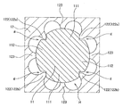
- FIG. 1 is a perspective view showing an appearance of a rotor of a rotating electrical machine according to an embodiment of the present invention.
- FIG. 2 is a cross-sectional view schematically showing the overall configuration of the rotor.
- FIG. 3 is a partial cross-sectional view schematically showing the configuration of the rotor shaft of the rotor and the periphery thereof.
- FIG. 4 is a partial cross-sectional view schematically showing a configuration between different shaft holding portions of the rotor.
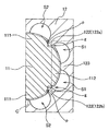
- FIG. 5 is a partial cross-sectional view schematically showing a configuration between a pair of inward protruding portions provided as a shaft holding portion in the rotor.
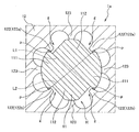
- FIG. 6 is a partial cross-sectional view similar to FIG.
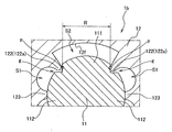
- FIG. 7 is a partial cross-sectional view similar to FIG. 5 schematically showing features of a rotor of a rotating electrical machine according to still another embodiment of the present invention.
- FIG. 1 shows the appearance of a rotor 1 of a rotating electrical machine according to an embodiment of the present invention when the rotor 1 is viewed obliquely from above.
- the rotor 1 includes a rotor shaft 11, a rotor core 12, and a pair of end plates 13.
- the rotor shaft 11 forms a rotating shaft of a rotating electric machine or motor to which the rotor 1 is applied.
- the rotor core 12 is fixedly supported on the outer periphery of the rotor shaft 11 and is composed of a plurality of electromagnetic steel plates stacked on each other in this embodiment.
- the number of layers of the electromagnetic steel sheets constituting the rotor core 12 is not limited to a plurality, and may be one.
- the electromagnetic steel sheets of the respective layers constituting the rotor core 12 do not have to be an annular single body, and may be configured by combining arc-shaped parts divided in the circumferential direction into an annular shape.
- the end plate 13 is made of a non-magnetic material, and is disposed on both sides of the rotor core 12 in the axial direction.
- the end plate 13 is clamped by bolts and nuts 14 to sandwich a plurality of electromagnetic steel plates constituting the rotor core 12.
- the rotor 1 has a plurality of permanent magnets and is disposed radially inward of a stator (not shown) provided with an electromagnetic coil to constitute a permanent magnet type synchronous motor.
- the rotating electrical machine or motor to which the rotor 1 is applied may be an electric motor that operates only as a motor, or may be a motor generator that has both functions of a motor and a generator.
- drive sources such as an electric vehicle or a hybrid vehicle, can be illustrated. It is possible to transmit the torque of the motor to the driving wheels of the vehicle and to propel the vehicle forward or backward.
- the rotor 1 constitutes a permanent magnet type synchronous motor.
- the motor to which the rotor 1 can be applied is not limited to this, and may be a winding field type synchronous motor or an induction motor. Also good.
- the arrangement of the permanent magnets in the case of a permanent magnet type synchronous motor may be an embedded type or a surface type. That is, the rotor 1 can be applied to all types of rotating electrical machines in which the rotor core 12 is fixedly supported on the outer periphery of the rotor shaft 11.
- FIG. 2 shows a configuration of a portion of the rotor 1 provided with the rotor core 12 by a cross section perpendicular to the rotation axis of the motor (hereinafter simply referred to as “rotation axis”).
- the rotor shaft 11 has a columnar shape or an elongated shape as a whole, and is inserted into the shaft insertion hole H of the rotor core 12 concentrically with the rotor core 12.
- the rotor core 12 has an annular shape as a whole, and has a plurality of permanent magnet insertion holes 12h formed on the outer periphery thereof so as to be arranged in the circumferential direction of the rotor core 12.
- the plurality of permanent magnets 121 provided in the rotor core 12 are inserted into the permanent magnet insertion holes 12 h and are fixed to the rotor core 12.
- the rotor core 12 is fixedly supported on the outer periphery of the rotor shaft 11 by engaging the shaft holding portion 122 provided on the inner peripheral portion thereof with the outer peripheral portion (first outer edge portion 111) of the rotor shaft 11.
- the rotor 1 constitutes an 8-pole motor
- the rotor core 12 has a total of 16 permanent magnets 121.
- the permanent magnets 121 are paired to form one pole and are arranged in a V-shape that spreads outward with respect to the radial direction of the rotor core 12.
- the total number of permanent magnets 121 and the number per one pole and the arrangement in the rotor core 12 are not limited to this, and the number of poles is four or the number of permanent magnets 121 per one is one. It is possible to
- FIG. 3 is a partially enlarged view of FIG. 2 and schematically shows the configuration of the rotor shaft 11 and its periphery in the rotor 1.
- the rotor shaft 11 has a first outer edge portion 111 projecting in the radial direction of the rotor shaft 11 on the outer peripheral portion thereof in a cross section perpendicular to the rotation axis, and is arranged in the circumferential direction of the rotor shaft 11 with respect to the first outer edge portion 111.
- first outer edge portions 111 and second outer edge portions 112 provided alternately.
- the term “projecting” of the first outer edge portion 111 means that the surface that engages the shaft holding portion 122 of the rotor core 12 when the rotor core 12 is fixed on the outer periphery of the rotor shaft 11 is formed.
- the first outer edge portion 111 is not particularly limited with respect to its height, and can take various forms such as a protruding portion, a huge portion, a raised portion, an enlarged diameter portion, a stepped portion, and a protruding portion. Is possible. Further, the first outer edge portion 111 may form a notch extending in the axial direction of the rotor shaft 11 rather than a protruding portion in a cross section perpendicular to the rotation axis. This is because the surface defining the notch can be the “engaging surface”.
- first outer edge portions are provided in total, one at each axially symmetric position with respect to the rotation axis, and one between each of the two first outer edge portions 111, Again, a total of two “second outer edges” 112 are provided alternately with the first outer edges 111 in the circumferential direction.
- first outer edge portion 111 is considered in consideration of the manufacturing convenience of the rotor core 12, specifically, the rollover of the electromagnetic steel sheet produced with variations in dimensions and magnetic properties according to the roll material part.
- the second outer edge 112 also has the same “projection” as the first outer edge 111.
- the rotor shaft 11 is provided with a total of four identical protruding portions every 90 degrees, but the rotor core 12 is fixed to the first outer edge portion 111 and the second outer edge portion 112.
- the first outer edge portion 111 and the second outer edge portion 112 is not only configured by one protrusion, but may be configured by a plurality of protrusions in appearance, in other words, as a set of a plurality of protrusions. Is possible.
- first outer edge portion 111 and the second outer edge portion 112 are configured by a plurality of protruding portions, respectively, protrude in the radial direction of the rotor shaft 11 as a whole, and are alternately arranged in the circumferential direction.
- the rotor core 12 has an annular shape as a whole, and includes one or one set of shaft holding portions 122 for each first outer edge portion 111 of the rotor shaft 11 on the inner peripheral portion where the shaft insertion hole H is formed.
- the rotor core 12 is fixed on the outer periphery of the rotor shaft 11 by holding the first outer edge portion 111 from both sides in the circumferential direction of the rotor shaft 11 by the shaft holding portion 122.
- the shaft holding portion 122 includes a pair of inwardly protruding portions 122a and 122b extending inward with respect to the radial direction of the rotor core 12 for each first outer edge portion 111, and the shaft holding portion 122, That is, in a state where the pair of inward protruding portions 122 a and 122 b are engaged with the first outer edge portion 111 and the rotor core 12 is fixed to the rotor shaft 11, the shaft holding portion 122 is the second outer edge portion of the rotor shaft 11. No contact with 112.
- the shaft holding portion 122 is “non-contact” with respect to the second outer edge portion 112.
- the shaft holding portion 122 is engaged with the first outer edge portion 111 of the rotor shaft 11 and protrudes inward in each pair.
- the deformation of the shaft holding part 122 by the first outer edge part 111 is not restricted by the second outer edge part 112 when the parts 122a and 122b are pressed in the direction away from each other by the first outer edge part 111.
- the shaft holding portion 122 is not restricted to the second outer edge portion 112, and the shaft holding portion 122 is not restricted to the second outer edge portion 112. This includes the case of being in a substantially non-contact state in which contact is made to such an extent that it is not affected.
- the shaft holding portion 122 of the rotor core 12 is paired for each first outer edge portion 111, for a total of two pairs ( That is, four inward projecting portions 122a and 122b are provided.
- the numbers of the first outer edge portions 111 and the shaft holding portions 122 are not limited to this, and can be set to appropriate numbers in consideration of the manufacturing convenience of the rotor core 12. Further, the number of the shaft holding portions 122 and the number of the first outer edge portions 111 do not need to match or correspond to each other, and a smaller number of shaft holding portions 122 than the first outer edge portions 111 may be provided.
- the number of the shaft holding portions 122 (the logarithm of the inward projecting portions 122a and 122b) is one, and four outer edge portions (two first outer edge portions 111 and two first Of the two outer edge portions 112), any one of the outer edge portions and the shaft holding portion 122 can be engaged with each other.
- FIG. 4 is a partially enlarged view of FIG. 3, and mainly shows the configuration of the rotor core 12 between the different shaft holding portions 122.
- FIG. 5 is a partially enlarged view of FIG. 3 and mainly shows the configuration of the rotor core 12 between the inwardly protruding portions 122a (122b) in each pair.
- the rotor core 12 includes a shaft holding portion 122 (one pair of inward projecting portions 122 a) that engages with one of the two first outer edge portions 111 of the rotor shaft 11, and the other.
- a recess S1 is provided in the inner peripheral portion between the shaft holding portion 122 (the other pair of inward protruding portions 122b) to be joined.
- FIG. 4 shows a portion where the recess S1 is provided by a dotted line. Due to the recess S ⁇ b> 1, a gap is formed between the rotor shaft 11 and the rotor core 12 between the different shaft holding portions 122.
- the rotor core 12 includes inwardly protruding portions in each pair (FIG. 5 shows one pair of the shaft holding portions 122 that engage with the first outer edge portion 111 of the rotor shaft 11.
- a recess S2 is provided in the inner peripheral portion between the inner projecting portions 122a.
- FIG. 5 shows a portion where the recess S2 is provided by a dotted line. Due to the recess S ⁇ b> 2, a gap is formed between the rotor shaft 11 and the rotor core 12 between the pair of inwardly protruding portions 122 a and 122 b provided as the shaft holding portion 122.
- the recesses S1 and S2 of the rotor core 12 are concentric with the rotor shaft 11 connecting the contact point p with the first outer edge portion 111 of the shaft holding portion 122 (inward protruding portions 122a and 122b) in a cross section perpendicular to the rotation axis. Is defined as an imaginary circle C, and extends outward from the imaginary circle C in the radial direction of the rotor core 12. In other words, the distance between the deepest part of the recesses S1 and S2 and the center of the rotor shaft 11 is longer than the radius of the virtual circle C.
- a gap formed by the recesses S1 and S2 is formed between the different shaft holding portions 122 (FIG. 4) and between the inwardly protruding portions 122a and 122b in each pair (FIG. 5).
- a core positioning portion 123 extending inward with respect to the radial direction is provided so as to be separated in the circumferential direction. The core positioning portion 123 determines the radial position of the rotor core 12 with respect to the rotor shaft 11.
- the core positioning portions 123 are provided every 45 degrees in the circumferential direction, and the positioning of the rotor shaft 11 is performed by the four core positioning portions 123 in total.
- the number of the core positioning portions 123 is not limited to this, and for example, the core positioning portions 123 are provided at axially symmetric positions with respect to the center of the rotor shaft 11, and the two core positioning portions 123 are used.
- the rotor shaft 11 may be positioned.
- the rotor 1 of the rotating electrical machine according to the present embodiment is configured as described above, and effects that can be obtained by the present embodiment will be described below.
- the shaft holding portion 122 is not in contact with the second outer edge portion 112 of the rotor shaft 11, so that the rotor core 12 is fixed to the rotor shaft 11. It is possible to suppress the above stress from extending in the radial direction of the rotor core 12 through the shaft holding portion 122. Thereby, the stress of the rotor core 12 outer periphery at the time of the high rotation of the rotor 1 can be reduced. For example, it is possible to reduce the stress acting on the permanent magnet insertion hole 12h, in particular, the corner of the outer periphery of the rotor core 12 that forms the flux barrier, and to increase the durability of the rotor core 12.
- recesses S1 and S2 are formed in the rotor core 12 between the different shaft holding portions 122 (FIG. 4) and between the inwardly protruding portions 122a and 122b in each pair (FIG. 5).
- the deformation of the shaft holding portion 122 (inward protruding portions 122a and 122b) when the rotor core 12 is fixed to the rotor shaft 11 is urged in the circumferential direction of the rotor core 12, and the stress is more surely applied in the radial direction. It is possible to suppress and further reduce the stress on the outer periphery of the rotor core 12 at the time of high rotation.
- the recesses S1 and S2 are extended to the outside in the radial direction with respect to the virtual circle C connecting the contact point p with the first outer edge portion 111 of the inward projecting portions 122a and 122b in a cross section perpendicular to the rotation axis. By doing so, the above effect becomes more remarkable.
- the core positioning portion 123 is provided separately from the shaft holding portion 122, thereby reducing the influence of the deformation of the shaft holding portion 122 on the positioning of the rotor core 12 and imbalance in the rotation of the rotor 1. Can be suppressed.
- FIG. 6 schematically shows a configuration of a rotor 1a of a rotating electrical machine according to another embodiment of the present invention by an enlarged cross section similar to FIG.
- FIG. 6 shows the tangent lines L1 and L2 with dotted lines.
- the configuration of the rotor core 12 is rotationally symmetric so that the tangent lines defined for the inwardly projecting portions 122a and 122b on the diagonal with respect to the center of the rotor shaft 11 coincide with each other. Duplicate.
- the rotor shaft 11 has a shape in which the tangents L1 and L2 on the rotor shaft 11 at the contact point p with respect to the first outer edge portion 111 of the inward projecting portions 122a and 122b in each pair intersect each other. It is possible to positively cause deformation of the inward projecting portions 122 a and 122 b when fixing the shaft to the rotor shaft 11 in the circumferential direction of the rotor core 12. Thereby, it can suppress that the stress at the time of fixing reaches the radial direction of the rotor core 12, and can reduce the stress of the outer periphery of the rotor core 12 at the time of high rotation.
- the direction in which the inward projecting portions 122a and 122b are deformed that is, the direction perpendicular to the tangents L1 and L2) and the direction of the centrifugal force generated in the inward projecting portions 122a and 122b (in this embodiment).
- the directions of the tangents L1 and L2) are orthogonal to each other, so that it is possible to secure an engagement margin with respect to the first outer edge portion 111 of the inward projecting portions 122a and 122b even under high rotation. It is possible to suppress a decrease in the holding force of the rotor core 12 above.
- FIG. 7 schematically shows a configuration of a rotor 1b of a rotating electrical machine according to still another embodiment of the present invention by an enlarged cross section similar to FIG.
- the core positioning portion 123 exists between the inwardly protruding portions 122a and 122b in each pair.
- the inner peripheral surface of the rotor core 12 between the inward projecting portions 122a and 122b has a relatively large curvature.
- the shape of the rotor core 12, particularly the inner peripheral surface 12 f thereof, is different from the previous embodiment, and the inner peripheral surface 12 f of the rotor core 12 is inwardly projecting in each pair (see FIG. , One pair of inwardly projecting portions 122a is formed in an arc shape protruding outward with respect to the radial direction of the rotor core 12.
- the inner peripheral surface 12f of the rotor core 12 between the inward protruding portions 122a (122b) is a contact point with respect to the first outer edge portion 111 of the inward protruding portion 122a (122b) in the cross section shown in FIG.
- a range R defined in the circumferential direction of the rotor core 12 by a pair of tangents at p extends beyond both sides in the circumferential direction.
- the length of the inner peripheral surface 12f is expanded in the circumferential direction, and the inner surface is fixed when the rotor core 12 is fixed. It is possible to disperse the stress (tensile stress) generated at the base of the protrusions 122a and 122b.
- the length of the inner peripheral surface 12f can be further increased, and the stress of the inward projecting portions 122a and 122b can be further increased. Can be dispersed.
- the configuration of the rotor shaft 11 and the rotor core 12, specifically, the first outer edge portion 111, the second outer edge portion 112, the shaft holding portion 122, and the core are considered in consideration of the manufacturing convenience of the rotor core 12.
- the arrangement of the positioning portion 123 has rotational symmetry or periodicity. That is, in the manufacture of the rotor core 12, the electromagnetic steel sheets are rotated by an appropriate number of sheets when laminating the electromagnetic steel sheets in consideration of the variation in dimensions and magnetic properties depending on the portion of the roll material from which the electromagnetic steel sheets are punched.
- the configuration of the rotor shaft 11 and the like is not limited to this, and may have no rotational symmetry.
- the first outer edge portion 111 and the second outer edge portion 112 have different ranges extending in the circumferential direction, or in the rotor core 12, the inner peripheral surface between different shaft holding portions 122 (FIG. 4).
- the inner peripheral surface between the inward projecting portions 122a and 122b in each pair (FIG. 5), the cross-sectional shape is different.
- the shaft holding portion 122 is provided on the rotor core 12, and the engagement portions (that is, the first outer edge portion 111) on the outer periphery of the rotor shaft 11 are formed by the pair of inward protruding portions 122 a and 122 b provided as the shaft holding portion 122. ).
- the relationship between the holding portion and the engaging portion is not limited to this, and it is also possible to replace the relationship between the two and provide the holding portion on the rotor shaft 11 side and the engaging portion on the rotor core 12 side. It is.
- the core holding portion including at least a pair of outward projecting portions is provided on the outer peripheral portion of the rotor shaft, and the core holding portion is engaged with the inner peripheral portion of the rotor core forming the shaft insertion hole.
- a part is provided.
- the outward projecting portions in each pair are provided at intervals in the circumferential direction of the rotor shaft, and the engaging portion on the inner periphery of the rotor core is engaged between the outward projecting portions in each pair.
- each of the outward projecting portions in each pair is in contact with the rotor core on the side opposite to the engaging portion in the circumferential direction.
Landscapes
- Engineering & Computer Science (AREA)
- Power Engineering (AREA)
- Iron Core Of Rotating Electric Machines (AREA)
- Connection Of Motors, Electrical Generators, Mechanical Devices, And The Like (AREA)
Abstract
回転電機のロータは、ロータシャフトと、ロータシャフトの外周上に固定支持されたロータコアと、を備える。ロータシャフトは、回転軸に垂直な断面において、当該口一タシャフ卜の径方向に突出する第1外縁部と、第1外縁部に対して当該ロータシャフ卜の周方向に並び、第1外縁部と交互に設けられた第2外縁部と、を有する。口ータコアは、ロータシャフトが挿入されるコア揷入孔を有し、コア揷入孔を形成する内周部に、第1外縁部を口一タシャフ卜の周方向の両側から保持するシャフ卜保持部を備える。シャフト保持部は、第2外縁部に対して非接触である。
Description
本発明は、ロータコアがロータシャフトの外周上に固定支持された回転電機のロータおよび回転電機のロータコア支持構造に関する。
JP5025258Bには、複数の永久磁石を有するロータコアが、ロータコアとは別体のロータシャフトまたはロータハブの外周上に固定支持された回転電機のロータに関し、次のような技術が記載されている。ロータコアのうち、ハブ挿入孔を形成するコア内周部と、永久磁石支持孔を形成するコア外周部と、の間の中間部に、肉抜き孔を周方向に隔てる複数のリブを設けるものである。リブは、コア内周部に接続するリブ一端部と、コア外周部に接続するリブ他端部と、がロータコアの周方向に互いにずらして形成され、リブ一端部とリブ他端部との間に、2つの湾曲部を有する(段落0016)。
上記文献に記載の技術によれば、ロータコアをロータハブの外周上に固定する際にコア外周部に生じる応力集中、具体的には、ロータコアの円環圧入ないし収縮締結により永久磁石支持孔を形成するコア外周部の隅部に生じる応力集中を緩和し、ロータコアの耐久性を高めることが可能である。しかし、ロータハブに対してロータコアが収縮締結により固定され、ロータハブとロータコアとの間でトルクを伝達させる際のロータコアの保持力がこの収縮締結のみにより形成されることから、所要の保持力を得るためには、ロータハブを大径にする必要があり、ロータ全体が大型となりがちである。
本発明は、以上の問題を考慮した回転電機のロータおよび回転電機のロータコア支持構造を提供することを目的とする。
—態様では、ロータシャフトと、ロータシャフトの外周上に固定支持されたロータコアと、を備える回転電機のロータが提供される。ロータシャフトは、回転軸に垂直な断面において、当該ロータシャフトの径方向に突出する第1外縁部と、第1外縁部に対して当該ロータシャフトの周方向に並び、第1外縁部と交互に設けられた第2外縁部と、を有し、ロータコアは、ロータシャフトが挿入されるコア挿入孔を有し、コア挿入孔を形成する内周部に、第1外縁部をロータシャフトの周方向の両側から保持し、第2外縁部に対して非接触であるシャフト保持部を備える。
他の態様では、回転電機のロータコア支持構造が提供される。
以下、図面を参照して、本発明の実施形態について説明する。
図1は、本発明の一実施形態に係る回転電機のロータ1の外観を、ロータ1を斜め上方からみた状態で示している。
ロータ1は、ロータシャフト11と、ロータコア12と、一対のエンドプレート13と、を備える。ロータシャフト11は、ロータ1が適用される回転電機ないしモータの回転軸を形成する。ロータコア12は、ロータシャフト11の外周上に固定支持され、本実施形態では、互いに積層された複数の電磁鋼板からなる。ロータコア12を構成する電磁鋼板の層数は、複数に限らず、1つであってもよい。さらに、ロータコア12を構成する各層の電磁鋼板は、円環状の単体である必要はなく、周方向に分割された円弧状の各部を円環状に組み合わせて構成されたものであってもよい。エンドプレート13は、非磁性材からなり、ロータコア12に対してその軸方向の両側に配置され、ボルトおよびナット14により締め付けられることで、ロータコア12を構成する複数の電磁鋼板を挟持する。
本実施形態において、ロータ1は、複数の永久磁石を有し、電磁コイルが備わるステータ(図示せず)に対し、その径方向の内側に配置されて、永久磁石型同期モータを構成する。ロータ1が適用される回転電機ないしモータは、発動機としてのみ動作する電動モータであってもよく、発動機および発電機の機能を併せ持つモータジェネレータであってもよい。そして、その用途として、電気自動車またはハイブリッド車等の駆動源を例示することができる。モータのトルクを車両の駆動輪に伝達させ、車両を前方または後方に推進することが可能である。本実施形態では、ロータ1により永久磁石型同期モータを構成するが、ロータ1が適用可能なモータは、これに限らず、巻線界磁型同期モータであってもよく、誘導モータであってもよい。そして、永久磁石型同期モータである場合の永久磁石の配置は、埋込型であってもよく、表面型であってもよい。つまり、ロータ1は、ロータコア12がロータシャフト11の外周上に固定支持される、あらゆる形態の回転電機に適応することが可能である。
図2は、ロータ1のうち、ロータコア12が備わる部分の構成を、モータの回転軸(以下単に「回転軸」という)に垂直な断面により示している。
ロータシャフト11は、全体として円柱状ないし長尺状をなし、ロータコア12のシャフト挿入孔Hに、ロータコア12と同心に挿入された状態にある。ロータコア12は、全体として円環状であり、その外周部にロータコア12の周方向に並べて形成された複数の永久磁石挿入孔12hを有する。ロータコア12に備わる複数の永久磁石121は、永久磁石挿入孔12hのそれぞれに挿入され、ロータコア12に対して固定された状態にある。ロータコア12は、その内周部に備わるシャフト保持部122がロータシャフト11の外周部(第1外縁部111)と係合することで、ロータシャフト11の外周上に固定支持されている。
本実施形態において、永久磁石121は、1極当たりに2個ずつ設けられ、ロータ1は、8極モータを構成し、ロータコア12は、合計で16個の永久磁石121を有する。永久磁石121は、一対で1つの極を形成し、ロータコア12の径方向に対して外向きに広がるV字をなす状態で配置されている。しかし、永久磁石121の合計および1極当たりの個数、ロータコア12における配置は、これに限定されるものではなく、極数を4極としたり、1極当たりの永久磁石121の個数を1個としたりすることが可能である。
図3は、図2の部分拡大図であり、ロータ1のうち、ロータシャフト11およびその周辺の構成を概略的に示している。
ロータシャフト11は、回転軸に垂直な断面において、その外周部に、ロータシャフト11の径方向に突出する第1外縁部111と、第1外縁部111に対してロータシャフト11の周方向に並び、第1外縁部111と交互に設けられた第2外縁部112と、を有する。ここで、第1外縁部111が「突出する」とは、ロータコア12をロータシャフト11の外周上に固定する際にロータコア12のシャフト保持部122が係合する面を形成する、という程度の意味であり、外周部の他の部位(例えば、第2外縁部112)と比べて径方向の外側にまで明確に延伸することを要するものではない。この意味で、第1外縁部111は、その高さに関して特に制限を受けず、突出部のほか、膨大部、隆起部、拡径部、段差部および突起部等、種々の形態をとることが可能である。さらに、第1外縁部111は、回転軸に垂直な断面において、突出部というよりも、むしろ、ロータシャフト11の軸方向に延在する切欠きを形成するものであってもよい。この切欠きを画定する面が上記「係合する面」となり得るからである。
本実施形態では、回転軸を基準とする軸対称の位置に1つずつ、合計で2つの「第1外縁部」111が設けられ、これら2つの第1外縁部111の間に1つずつ、やはり、合計で2つの「第2外縁部」112が、周方向に対して第1外縁部111と交互に設けられている。本実施形態では、ロータコア12の製造上の都合、具体的には、ロール材の部位に応じた寸法および磁気特性のばらつきをもって作製された電磁鋼板の転積を考慮して、第1外縁部111だけでなく、第2外縁部112もまた第1外縁部111と同様の「突出部」の形態をなす。つまり、本実施形態では、ロータシャフト11において、合計で4つの同形の突出部が90度毎に備わることになるが、第1外縁部111と第2外縁部112とは、ロータコア12が固定された状態でのシャフト保持部122との接触または非接触の関係により、異なる性質の「突出部」として区別される。さらに、第1外縁部111および第2外縁部112は、夫々1つの突出部により構成するばかりでなく、見かけ上複数の突出部により、換言すれば、複数の突出部の集合として構成することも可能である。これは、例えば、ロータシャフト11を軸方向にみた図3の断面において、第1外縁部111および第2外縁部112の外周に溝または切欠きを設けることなどによる。第1外縁部111および第2外縁部112は、夫々複数の突出部により構成されて、全体としてロータシャフト11の径方向に突出し、周方向に交互に並んだ状態にあるものとして理解される。
ロータコア12は、全体として円環状をなし、シャフト挿入孔Hを形成する内周部に、ロータシャフト11の第1外縁部111毎に1つないし1組のシャフト保持部122を備える。ロータコア12は、シャフト保持部122により第1外縁部111をロータシャフト11の周方向の両側から保持することで、ロータシャフト11の外周上に固定されている。本実施形態において、シャフト保持部122は、第1外縁部111毎に、ロータコア12の径方向に対して内向きに延びる1対の内方突出部122a、122bにより構成され、シャフト保持部122、つまり、1対の内方突出部122a、122bが第1外縁部111と係合し、ロータコア12がロータシャフト11に固定された状態で、シャフト保持部122は、ロータシャフト11の第2外縁部112に対して非接触である。ここで、シャフト保持部122が第2外縁部112に対して「非接触である」とは、シャフト保持部122がロータシャフト11の第1外縁部111と係合し、各対における内方突出部122a、122bが第1外縁部111により互いに離間する方向に押圧されたときに、第1外縁部111によるシャフト保持部122の変形が第2外縁部112による拘束を受けないことをいい、図3に示すように、シャフト保持部122と第2外縁部112との間に目視可能なほどの明確な隙間9が存在する場合に限らず、シャフト保持部122が第2外縁部112に上記拘束を受けない程度に接触した実質的な非接触状態にある場合を含む意味である。
本実施形態では、ロータシャフト111に2つの第1外縁部111を設けたこととの関係で、ロータコア12のシャフト保持部122として、第1外縁部111毎に1対ずつ、合計で2対(つまり、4つ)の内方突出部122a、122bが設けられている。しかし、第1外縁部111およびシャフト保持部122の個数は、これに限定されるものではなく、ロータコア12の製造上の都合等を考慮して適宜の個数に設定することが可能である。さらに、シャフト保持部122の個数と第1外縁部111の個数とが一致ないし対応する必要もなく、第1外縁部111よりも少ない個数のシャフト保持部122が設けられてもよい。例えば、図3に示すロータシャフト11に対し、シャフト保持部122の個数(内方突出部122a、122bの対数)を1つとし、4つの外縁部(2つの第1外縁部111および2つの第2外縁部112)のうち、いずれか1つの外縁部とシャフト保持部122が係合するように構成することも可能である。
図4は、図3の部分拡大図であり、異なるシャフト保持部122の間におけるロータコア12の構成を中心に示している。
図5は、図3の部分拡大図であり、各対における内方突出部122a(122b)の間におけるロータコア12の構成を中心に示している。
ロータコア12は、図4に示すように、ロータシャフト11に備わる2つの第1外縁部111のうち一方と係合するシャフト保持部122(一方の対の内方突出部122a)と、他方と係合するシャフト保持部122(他方の対の内方突出部122b)と、の間の内周部に凹所S1を有する。図4は、凹所S1が設けられる箇所を点線で示す。凹所S1により、異なるシャフト保持部122の間で、ロータシャフト11とロータコア12との間に空隙が形成される。
さらに、ロータコア12は、図5に示すように、ロータシャフト11の第1外縁部111と係合するシャフト保持部122のそれぞれにおいて、各対における内方突出部(図5は、一方の対の内方突出部122aを示す)の間の内周部に凹所S2を有する。図5は、凹所S2が設けられる箇所を点線で示す。凹所S2により、シャフト保持部122として備わる各対の内方突出部122a、122bの間で、ロータシャフト11とロータコア12との間に空隙が形成される。
ロータコア12の凹所S1、S2は、回転軸に垂直な断面において、シャフト保持部122(内方突出部122a、122b)の第1外縁部111に対する接点pを結んだロータシャフト11と同心の円を仮想円Cとして、ロータコア12の径方向に関して仮想円Cよりも外側にまで延設されている。換言すれば、凹所S1、S2のうち最も深い部位とロータシャフト11の中心との間の距離は、仮想円Cの半径よりも長い。
さらに、異なるシャフト保持部122の間(図4)と、各対における内方突出部122a、122bの間(図5)と、のそれぞれにおいて、凹所S1、S2により形成される空隙をロータコア12の周方向に隔てるように、径方向に対して内向きに延びるコア位置決め部123が設けられている。コア位置決め部123により、ロータコア12のロータシャフト11に対する径方向の位置が定められる。
本実施形態では、コア位置決め部123が周方向に45度毎に設けられ、ロータシャフト11の位置決めが合計で4つのコア位置決め部123により実施される。しかし、コア位置決め部123の個数は、これに限定されるものではなく、例えば、コア位置決め部123をロータシャフト11の中心を基準とする軸対称の位置に夫々設け、2つのコア位置決め部123によりロータシャフト11の位置決めを行うようにしてもよい。
本実施形態に係る回転電機のロータ1は、以上のように構成され、本実施形態により得ることのできる効果について、以下に説明する。
第1に、ロータコア12の内周部に形成されたシャフト保持部122により、ロータシャフト11の第1外縁部111を周方向の両側から保持することで、ロータシャフト11とロータコア12との間でのトルクの伝達が、シャフト保持部122の剛性により達成される。これにより、トルクの伝達がロータコアの収縮締結のみにより達成される場合と比較して、ロータシャフト11の小径化が可能となり、ロータ1全体の小型化を促進することができる。
さらに、ロータコア12がロータシャフト11の外周上に固定された状態で、シャフト保持部122がロータシャフト11の第2外縁部112と非接触であることで、ロータコア12をロータシャフト11に固定する際の応力がシャフト保持部122を通じてロータコア12の径方向に及ぶのを抑制することが可能となる。これにより、ロータ1の高回転時におけるロータコア12外周の応力を低減することができる。例えば、永久磁石挿入孔12h、特にそのフラックスバリアを形成するロータコア12外周の隅部に作用する応力を低減し、ロータコア12の耐久性を高めることができる。
第2に、異なるシャフト保持部122の間(図4)と、各対における内方突出部122a、122bの間(図5)と、のそれぞれにおいて、ロータコア12に凹所S1、S2を形成することで、ロータコア12をロータシャフト11に固定する際のシャフト保持部122(内方突出部122a、122b)の変形がロータコア12の周方向に促され、応力が径方向に及ぶのをより確実に抑制し、高回転時におけるロータコア12外周の応力を一層低減することが可能となる。ここで、凹所S1、S2を、回転軸に垂直な断面において、内方突出部122a、122bの第1外縁部111に対する接点pを結んだ仮想円Cよりも径方向の外側にまで延設することで、上記効果がより顕著となる。
第3に、ロータコア12において、コア位置決め部123をシャフト保持部122とは別に設けたことで、シャフト保持部122の変形がロータコア12の位置決めに及ぼす影響を軽減し、ロータ1の回転に不均衡が生じるのを抑制することができる。
本発明の他の実施形態について、以下に説明する。
図6は、本発明の他の実施形態に係る回転電機のロータ1aの構成を、その特徴を中心として図3と同様の拡大断面により概略的に示している。
先の実施形態(図3)との相違点を中心に説明すると、先の実施形態では、回転軸に垂直な断面において、各対における内方突出部122a、122bの第1外縁部111に対する接点pにおけるロータシャフト11上の接線(シャフト保持部122毎に一対の接線L1、L2が定められる)が互いに平行である。これに対し、本実施形態では、先の実施形態とはロータシャフト11の形状が相違し、同様にして定められる一対の接線L1、L2が互いに交差し、特にロータシャフト11の中心を通過する。図6は、接線L1、L2を点線で示す。本実施形態では、ロータコア12の構成に回転対称性を持たせており、これにより、ロータシャフト11の中心を基準とした対角上にある内方突出部122a、122bについて定められる接線が一致または重複する。
このように、ロータシャフト11を、各対における内方突出部122a、122bの第1外縁部111に対する接点pにおけるロータシャフト11上の接線L1、L2が互いに交差する形状としたことで、ロータコア12をロータシャフト11に固定する際の内方突出部122a、122bの変形を、ロータコア12の周方向に積極的に生じさせることが可能となる。これにより、固定する際の応力がロータコア12の径方向に及ぶのを抑制し、高回転時におけるロータコア12外周の応力を低減することができる。
さらに、ロータコア12の固定に際して内方突出部122a、122bが変形する方向(つまり、接線L1、L2に垂直な方向)と、内方突出部122a、122bに生じる遠心力の方向(本実施形態では、接線L1、L2の方向)と、が直交するため、高回転下にあっても内方突出部122a、122bの第1外縁部111に対する係合代を確保することが可能となり、ロータシャフト11上でのロータコア12の保持力の低下を抑制することができる。
図7は、本発明の更に別の実施形態に係る回転電機のロータ1bの構成を、その特徴を中心として図5と同様の拡大断面により概略的に示している。
先の実施形態(図5)との相違点を中心に説明すると、先の実施形態では、各対における内方突出部122a、122bの間にコア位置決め部123が存在し、このことも相俟って、回転軸に垂直な断面において、内方突出部122a、122bの間におけるロータコア12の内周面が比較的大きな曲率を有する。これに対し、本実施形態では、先の実施形態とはロータコア12、特にその内周面12fの形状が相違し、ロータコア12の内周面12fが、各対における内方突出部(図7は、一方の対の内方突出部122aを示す)の間で、ロータコア12の径方向に対して外向きに凸となる円弧状をなす。
さらに、本実施形態では、内方突出部122a(122b)の間におけるロータコア12の内周面12fが、図7に示す断面において、内方突出部122a(122b)の第1外縁部111に対する接点pにおける一対の接線によりロータコア12の周方向に定められる範囲Rを、周方向の両側に超えて延在する。
このように、ロータコア12の内方突出部122a、122bの間における内周面12fを円弧状とすることで、内周面12fの長さを周方向に拡大し、ロータコア12の固定に際して内方突出部122a、122bの根本に生じる応力(引張応力)を分散させることが可能となる。
さらに、ロータコア12の内周面12fを、範囲Rを超えて延在させることで、内周面12fの長さをさらに拡大することが可能となり、内方突出部122a、122bの応力をより広く分散させることができる。
以上の説明では、ロータコア12の製造上の都合等を考慮して、ロータシャフト11およびロータコア12の構成、具体的には、第1外縁部111、第2外縁部112、シャフト保持部122およびコア位置決め部123の配置に、回転対称性または周期性を持たせるようにした。つまり、ロータコア12の製造では、電磁鋼板を打ち抜くロール材の部位に応じて寸法および磁気特性に生じるバラツキを考慮し、電磁鋼板の積層に際し、適宜の枚数毎に電磁鋼板を回転させるが(これを「転積」という場合がある)、ロータシャフト11等の構成に回転対称性を持たせることで、積層時の向きないし回転位置に拘らず共通の電磁鋼板の使用を可能とするものである。しかし、ロータシャフト11等の構成は、これに限定されるものではなく、回転対称性のないものであってもよい。例えば、ロータシャフト11において、第1外縁部111と第2外縁部112とで、周方向に及ぶ範囲を異ならせたり、ロータコア12において、異なるシャフト保持部122の間(図4)の内周面と各対における内方突出部122a、122bの間(図5)の内周面とで、断面の形状を異ならせたりする。
さらに、以上の説明では、ロータコア12にシャフト保持部122を設け、シャフト保持部122として備わる一対の内方突出部122a、122bにより、ロータシャフト11外周の係合部(つまり、第1外縁部111)を保持する構成とした。しかし、保持部と係合部との関係は、これに限定されるものではなく、両者の関係を入れ替えて、保持部をロータシャフト11側に、係合部をロータコア12側に設けることも可能である。
具体的には、ロータシャフトの外周部に、少なくとも一対の外方突出部からなるコア保持部を設ける一方、シャフト挿入孔を形成するロータコアの内周部に、コア保持部が係合する係合部を設けるのである。各対における外方突出部は、ロータシャフトの周方向に互いに間隔を空けて設けられ、各対における外方突出部の間に、ロータコア内周の係合部が係合する。ここで、各対における外方突出部のそれぞれは、係合部とは周方向の反対側で、ロータコアに対して非接触である。
以上、本発明の実施形態について説明したが、上記実施形態は、本発明の適用例の一部を示したに過ぎず、本発明の技術的範囲を、上記実施形態の具体的構成に限定する趣旨ではない。上記実施形態に対し、請求の範囲に記載した事項の範囲内で様々な変更および修正が可能である。
Claims (10)
- ロータシャフトと、
前記ロータシャフトの外周上に固定支持されたロータコアと、
を備え、
前記ロータシャフトは、回転軸に垂直な断面において、当該ロータシャフトの径方向に突出する第1外縁部と、前記第1外縁部に対して当該ロータシャフトの周方向に並び、前記第1外縁部と交互に設けられた第2外縁部と、を有し、
前記ロータコアは、前記ロータシャフトが挿入されるコア挿入孔を有し、前記コア挿入孔を形成する内周部に、前記第1外縁部を前記ロータシャフトの周方向の両側から保持するシャフト保持部を備え、
前記シャフト保持部は、前記第2外縁部に対して非接触である、
回転電機のロータ。 - 請求項1に記載の回転電機のロータであって、
前記ロータシャフトは、複数の前記第1外縁部を有し、
前記シャフト保持部は、前記ロータコアの内周部の内方突出部として構成され、周方向に隣り合う前記第1外縁部を保持するシャフト保持部の間に、前記ロータコアの凹所を形成する、
回転電機のロータ。 - 請求項1または2に記載の回転電機のロータであって、
前記シャフト保持部は、前記ロータコアの内周部に設けられた一対の内方突出部からなり、前記一対の内方突出部の間に、前記ロータコアの凹所を形成する、
回転電機のロータ。 - 請求項2または3に記載の回転電機のロータであって、
前記凹所は、前記回転軸に垂直な断面において、前記内方突出部の前記第1外縁部に対する接点を結んだ前記ロータシャフトと同心の仮想円よりも前記ロータコアの径方向に関して外側にまで延在する、
回転電機のロータ。 - 請求項2~4のいずれか一項に記載の回転電機のロータであって、
前記ロータコアは、前記凹所により前記ロータシャフトとの間に空隙を形成し、さらに、前記空隙を当該ロータコアの周方向に隔てるように延伸し、当該ロータコアの前記ロータシャフトに対する径方向の位置を定めるコア位置決め部を備える、
回転電機のロータ。 - 請求項2~5のいずれか一項に記載の回転電機のロータであって、
前記ロータシャフトは、前記回転軸に垂直な断面において、前記内方突出部の前記第1外縁部に対する接点における当該ロータシャフト上の接線が互いに交差する形状である、
回転電機のロータ。 - 請求項1に記載の回転電機のロータであって、
前記シャフト保持部は、前記ロータコアの内周部に設けられた一対の内方突出部からなり、
前記一対の内方突出部の間における前記ロータコアの内周面は、前記回転軸に垂直な断面において、前記ロータコアの径方向に対して外向きに凸となる円弧状をなす、
回転電機のロータ。 - 請求項7に記載の回転電機のロータであって、
前記ロータコアの内周面は、前記回転軸に垂直な断面において、前記一対の内方突出部の前記第1外縁部に対する接点における接線により周方向に定められる範囲を超えて延在する、
回転電機のロータ。 - ロータコアをロータシャフトの外周上に固定支持する、回転電機のロータコア支持構造であって、
前記ロータコアは、前記ロータシャフトが挿入されるシャフト挿入孔を有し、前記シャフト挿入孔を形成する内周部に、少なくとも一対の内方突出部からなるシャフト保持部を備え、前記各対における前記内方突出部は、周方向に互いに間隔を空けて設けられ、
前記ロータシャフトは、その外周部に、前記各対における前記内方突出部の間に係合する係合部を備え、
前記各対における前記内方突出部のそれぞれは、前記係合部とは周方向の反対側で、前記ロータシャフトに対して非接触である、
回転電機のロータコア支持構造。 - ロータコアをロータシャフトの外周上に固定支持する、回転電機のロータコア支持構造であって、
前記ロータコアは、前記ロータシャフトが挿入されるシャフト挿入孔を有し、
前記ロータシャフトは、その外周部に、少なくとも一対の外方突出部からなるコア保持部を備え、前記各対における前記外方突出部は、周方向に互いに間隔を空けて設けられ、
前記ロータコアは、前記シャフト挿入孔を形成する内周部に、前記各対における前記外方突出部の間に係合する係合部を備え、
前記各対における前記外方突出部のそれぞれは、前記係合部とは周方向の反対側で、前記ロータコアに対して非接触である、
回転電機のロータコア支持構造。
Priority Applications (5)
| Application Number | Priority Date | Filing Date | Title |
|---|---|---|---|
| EP18908571.5A EP3764520B1 (en) | 2018-03-09 | 2018-03-09 | Rotor for dynamo-electric machine, and rotor core support structure for dynamo-electric machine |
| US16/979,011 US11303172B2 (en) | 2018-03-09 | 2018-03-09 | Rotor for rotating electrical machine and rotor core support structure for rotating electrical machine |
| PCT/IB2018/000373 WO2019171099A1 (ja) | 2018-03-09 | 2018-03-09 | 回転電機のロータおよび回転電機の口一タコア支持構造 |
| CN201880090986.2A CN112119572B (zh) | 2018-03-09 | 2018-03-09 | 旋转电机的转子以及旋转电机的转子芯支承构造 |
| JP2020504460A JP6947284B2 (ja) | 2018-03-09 | 2018-03-09 | 回転電機のロータおよび回転電機のロータコア支持構造 |
Applications Claiming Priority (1)
| Application Number | Priority Date | Filing Date | Title |
|---|---|---|---|
| PCT/IB2018/000373 WO2019171099A1 (ja) | 2018-03-09 | 2018-03-09 | 回転電機のロータおよび回転電機の口一タコア支持構造 |
Publications (1)
| Publication Number | Publication Date |
|---|---|
| WO2019171099A1 true WO2019171099A1 (ja) | 2019-09-12 |
Family
ID=67845889
Family Applications (1)
| Application Number | Title | Priority Date | Filing Date |
|---|---|---|---|
| PCT/IB2018/000373 Ceased WO2019171099A1 (ja) | 2018-03-09 | 2018-03-09 | 回転電機のロータおよび回転電機の口一タコア支持構造 |
Country Status (5)
| Country | Link |
|---|---|
| US (1) | US11303172B2 (ja) |
| EP (1) | EP3764520B1 (ja) |
| JP (1) | JP6947284B2 (ja) |
| CN (1) | CN112119572B (ja) |
| WO (1) | WO2019171099A1 (ja) |
Cited By (6)
| Publication number | Priority date | Publication date | Assignee | Title |
|---|---|---|---|---|
| CN111769668A (zh) * | 2020-07-09 | 2020-10-13 | 精进电动科技股份有限公司 | 一种内置式永磁体电机转子结构 |
| JP2021045007A (ja) * | 2019-09-13 | 2021-03-18 | アイシン・エィ・ダブリュ株式会社 | ロータ |
| FR3101491A1 (fr) * | 2019-10-01 | 2021-04-02 | Nidec Psa Emotors | Rotor de machine electrique tournante |
| FR3103651A1 (fr) | 2019-11-26 | 2021-05-28 | Renault Sas | Procédé de montage d’un rotor de machine électrique |
| JP2024004983A (ja) * | 2022-06-29 | 2024-01-17 | トヨタ自動車株式会社 | ロータ |
| WO2025105130A1 (ja) * | 2023-11-14 | 2025-05-22 | 株式会社エフ・シー・シー | モータの回転子 |
Families Citing this family (1)
| Publication number | Priority date | Publication date | Assignee | Title |
|---|---|---|---|---|
| CN118199296B (zh) * | 2024-05-15 | 2024-08-06 | 库卡机器人(广东)有限公司 | 电机转子、伺服电机及工业机器人 |
Citations (4)
| Publication number | Priority date | Publication date | Assignee | Title |
|---|---|---|---|---|
| JPS5025258B1 (ja) | 1969-10-20 | 1975-08-22 | ||
| JPS55145847U (ja) * | 1979-04-09 | 1980-10-20 | ||
| JP2009060738A (ja) * | 2007-08-31 | 2009-03-19 | Honda Motor Co Ltd | 回転電機 |
| JP2014176218A (ja) * | 2013-03-11 | 2014-09-22 | Mitsubishi Electric Corp | 回転子および当該回転子を有する回転電機、更には当該回転子の製造方法 |
Family Cites Families (10)
| Publication number | Priority date | Publication date | Assignee | Title |
|---|---|---|---|---|
| US4987330A (en) * | 1990-01-16 | 1991-01-22 | General Motors Corporation | Rotor lamination assembly for a dynamoelectric machine |
| JP5025258B2 (ja) | 2006-12-27 | 2012-09-12 | 本田技研工業株式会社 | 回転電機のロータ |
| JP2008187804A (ja) * | 2007-01-29 | 2008-08-14 | Toyota Motor Corp | 回転子およびこの回転子を備えた回転電機 |
| JP2011239612A (ja) * | 2010-05-12 | 2011-11-24 | Denso Corp | 回転電機の回転子 |
| JP5707863B2 (ja) * | 2010-10-29 | 2015-04-30 | 株式会社明電舎 | 電動機のロータ構造 |
| JP5423738B2 (ja) * | 2011-08-03 | 2014-02-19 | 株式会社安川電機 | 回転電機 |
| JP5817675B2 (ja) | 2012-08-06 | 2015-11-18 | トヨタ自動車株式会社 | ロータシャフトの固定構造 |
| JP5728038B2 (ja) * | 2013-01-29 | 2015-06-03 | 株式会社豊田自動織機 | 回転電機の回転子およびその製造方法 |
| JP2014173585A (ja) * | 2013-03-13 | 2014-09-22 | Hitachi Automotive Systems Ltd | 電動流体ポンプ |
| JP6278333B2 (ja) * | 2013-09-03 | 2018-02-14 | アイシン精機株式会社 | 電動モータ |
-
2018
- 2018-03-09 CN CN201880090986.2A patent/CN112119572B/zh active Active
- 2018-03-09 US US16/979,011 patent/US11303172B2/en active Active
- 2018-03-09 JP JP2020504460A patent/JP6947284B2/ja active Active
- 2018-03-09 EP EP18908571.5A patent/EP3764520B1/en active Active
- 2018-03-09 WO PCT/IB2018/000373 patent/WO2019171099A1/ja not_active Ceased
Patent Citations (4)
| Publication number | Priority date | Publication date | Assignee | Title |
|---|---|---|---|---|
| JPS5025258B1 (ja) | 1969-10-20 | 1975-08-22 | ||
| JPS55145847U (ja) * | 1979-04-09 | 1980-10-20 | ||
| JP2009060738A (ja) * | 2007-08-31 | 2009-03-19 | Honda Motor Co Ltd | 回転電機 |
| JP2014176218A (ja) * | 2013-03-11 | 2014-09-22 | Mitsubishi Electric Corp | 回転子および当該回転子を有する回転電機、更には当該回転子の製造方法 |
Non-Patent Citations (1)
| Title |
|---|
| See also references of EP3764520A4 |
Cited By (10)
| Publication number | Priority date | Publication date | Assignee | Title |
|---|---|---|---|---|
| JP2021045007A (ja) * | 2019-09-13 | 2021-03-18 | アイシン・エィ・ダブリュ株式会社 | ロータ |
| FR3101491A1 (fr) * | 2019-10-01 | 2021-04-02 | Nidec Psa Emotors | Rotor de machine electrique tournante |
| WO2021064315A1 (fr) * | 2019-10-01 | 2021-04-08 | Nidec Psa Emotors | Rotor de machine electrique tournante |
| FR3103651A1 (fr) | 2019-11-26 | 2021-05-28 | Renault Sas | Procédé de montage d’un rotor de machine électrique |
| CN111769668A (zh) * | 2020-07-09 | 2020-10-13 | 精进电动科技股份有限公司 | 一种内置式永磁体电机转子结构 |
| EP3937351A1 (en) * | 2020-07-09 | 2022-01-12 | Jing-Jin Electric Technologies Co., Ltd. | Rotor structure of interior permanent magnet motor |
| US11699931B2 (en) | 2020-07-09 | 2023-07-11 | Jing-Jin Electric Technologies Co., Ltd. | Rotor structure of interior permanent magnet motor |
| JP2024004983A (ja) * | 2022-06-29 | 2024-01-17 | トヨタ自動車株式会社 | ロータ |
| US12341383B2 (en) | 2022-06-29 | 2025-06-24 | Toyota Jidosha Kabushiki Kaisha | Rotor |
| WO2025105130A1 (ja) * | 2023-11-14 | 2025-05-22 | 株式会社エフ・シー・シー | モータの回転子 |
Also Published As
| Publication number | Publication date |
|---|---|
| CN112119572A (zh) | 2020-12-22 |
| EP3764520B1 (en) | 2022-08-31 |
| JP6947284B2 (ja) | 2021-10-13 |
| US20200412191A1 (en) | 2020-12-31 |
| US11303172B2 (en) | 2022-04-12 |
| EP3764520A4 (en) | 2021-03-10 |
| EP3764520A1 (en) | 2021-01-13 |
| JPWO2019171099A1 (ja) | 2021-03-11 |
| CN112119572B (zh) | 2023-02-28 |
Similar Documents
| Publication | Publication Date | Title |
|---|---|---|
| JP6947284B2 (ja) | 回転電機のロータおよび回転電機のロータコア支持構造 | |
| US11056934B2 (en) | Rotary electric machine with a stator core with teeth having different protrusion portions heights | |
| JP6806352B2 (ja) | 回転電機、回転子鉄心の製造方法 | |
| US9407116B2 (en) | Multi-gap rotary machine with dual stator and one rotor with dual permanent magnets and salient poles with dimensions and ratios for torque maximization | |
| JP5722301B2 (ja) | 埋込磁石型同期電動機の回転子および埋込磁石型同期電動機 | |
| US20130285500A1 (en) | Rotor for a motor and a motor | |
| JPWO2014115436A1 (ja) | 永久磁石式回転電機 | |
| JP2018153047A (ja) | 回転電機のロータ | |
| JPWO2017141361A1 (ja) | 回転電機及び回転電機の製造方法 | |
| WO2017195498A1 (ja) | 回転子および回転電機 | |
| JP2017055560A (ja) | 永久磁石式回転電機 | |
| US11611251B2 (en) | Motor having asymmetric rotor core | |
| WO2020100675A1 (ja) | 回転子およびそれを備えた回転電気機械 | |
| JP7615913B2 (ja) | 回転電機 | |
| JP6117608B2 (ja) | 回転電機の積層鉄心 | |
| JP2005051929A (ja) | 電動機 | |
| JP7124247B1 (ja) | 回転電機の回転子 | |
| JP2020014336A (ja) | 回転電気機械 | |
| JP2015056911A (ja) | ロータ及びこのロータを備える回転電機 | |
| JP2015162980A (ja) | 回転電機の永久磁石埋設型回転子、及び回転電機 | |
| KR20160057766A (ko) | 계자권선형 구동모터의 회전자 | |
| WO2019189599A1 (ja) | ロータ、モータおよび電動パワーステアリング装置 | |
| JP5303907B2 (ja) | アキシャルギャップ型回転電機及び界磁子用コア | |
| WO2024057837A1 (ja) | 回転電機のコア及び回転電機 | |
| JP2025067124A (ja) | 回転電機の回転子 |
Legal Events
| Date | Code | Title | Description |
|---|---|---|---|
| 121 | Ep: the epo has been informed by wipo that ep was designated in this application |
Ref document number: 18908571 Country of ref document: EP Kind code of ref document: A1 |
|
| ENP | Entry into the national phase |
Ref document number: 2020504460 Country of ref document: JP Kind code of ref document: A |
|
| NENP | Non-entry into the national phase |
Ref country code: DE |
|
| WWE | Wipo information: entry into national phase |
Ref document number: 2018908571 Country of ref document: EP |