WO2019171549A1 - 電動機駆動装置および空気調和機 - Google Patents
電動機駆動装置および空気調和機 Download PDFInfo
- Publication number
- WO2019171549A1 WO2019171549A1 PCT/JP2018/009060 JP2018009060W WO2019171549A1 WO 2019171549 A1 WO2019171549 A1 WO 2019171549A1 JP 2018009060 W JP2018009060 W JP 2018009060W WO 2019171549 A1 WO2019171549 A1 WO 2019171549A1
- Authority
- WO
- WIPO (PCT)
- Prior art keywords
- connection state
- electric motor
- voltage
- inverter
- drive device
- Prior art date
- Legal status (The legal status is an assumption and is not a legal conclusion. Google has not performed a legal analysis and makes no representation as to the accuracy of the status listed.)
- Ceased
Links
Images



Classifications
-
- H—ELECTRICITY
- H02—GENERATION; CONVERSION OR DISTRIBUTION OF ELECTRIC POWER
- H02P—CONTROL OR REGULATION OF ELECTRIC MOTORS, ELECTRIC GENERATORS OR DYNAMO-ELECTRIC CONVERTERS; CONTROLLING TRANSFORMERS, REACTORS OR CHOKE COILS
- H02P25/00—Arrangements or methods for the control of AC motors characterised by the kind of AC motor or by structural details
- H02P25/16—Arrangements or methods for the control of AC motors characterised by the kind of AC motor or by structural details characterised by the circuit arrangement or by the kind of wiring
- H02P25/18—Arrangements or methods for the control of AC motors characterised by the kind of AC motor or by structural details characterised by the circuit arrangement or by the kind of wiring with arrangements for switching the windings, e.g. with mechanical switches or relays
- H02P25/184—Arrangements or methods for the control of AC motors characterised by the kind of AC motor or by structural details characterised by the circuit arrangement or by the kind of wiring with arrangements for switching the windings, e.g. with mechanical switches or relays wherein the motor speed is changed by switching from a delta to a star, e.g. wye, connection of its windings, or vice versa
-
- H—ELECTRICITY
- H02—GENERATION; CONVERSION OR DISTRIBUTION OF ELECTRIC POWER
- H02P—CONTROL OR REGULATION OF ELECTRIC MOTORS, ELECTRIC GENERATORS OR DYNAMO-ELECTRIC CONVERTERS; CONTROLLING TRANSFORMERS, REACTORS OR CHOKE COILS
- H02P27/00—Arrangements or methods for the control of AC motors characterised by the kind of supply voltage
- H02P27/04—Arrangements or methods for the control of AC motors characterised by the kind of supply voltage using variable-frequency supply voltage, e.g. inverter or converter supply voltage
- H02P27/06—Arrangements or methods for the control of AC motors characterised by the kind of supply voltage using variable-frequency supply voltage, e.g. inverter or converter supply voltage using DC to AC converters or inverters
-
- H—ELECTRICITY
- H02—GENERATION; CONVERSION OR DISTRIBUTION OF ELECTRIC POWER
- H02P—CONTROL OR REGULATION OF ELECTRIC MOTORS, ELECTRIC GENERATORS OR DYNAMO-ELECTRIC CONVERTERS; CONTROLLING TRANSFORMERS, REACTORS OR CHOKE COILS
- H02P27/00—Arrangements or methods for the control of AC motors characterised by the kind of supply voltage
- H02P27/04—Arrangements or methods for the control of AC motors characterised by the kind of supply voltage using variable-frequency supply voltage, e.g. inverter or converter supply voltage
- H02P27/06—Arrangements or methods for the control of AC motors characterised by the kind of supply voltage using variable-frequency supply voltage, e.g. inverter or converter supply voltage using DC to AC converters or inverters
- H02P27/08—Arrangements or methods for the control of AC motors characterised by the kind of supply voltage using variable-frequency supply voltage, e.g. inverter or converter supply voltage using DC to AC converters or inverters with pulse width modulation
-
- H—ELECTRICITY
- H02—GENERATION; CONVERSION OR DISTRIBUTION OF ELECTRIC POWER
- H02P—CONTROL OR REGULATION OF ELECTRIC MOTORS, ELECTRIC GENERATORS OR DYNAMO-ELECTRIC CONVERTERS; CONTROLLING TRANSFORMERS, REACTORS OR CHOKE COILS
- H02P29/00—Arrangements for regulating or controlling electric motors, appropriate for both AC and DC motors
- H02P29/02—Providing protection against overload without automatic interruption of supply
- H02P29/024—Detecting a fault condition, e.g. short circuit, locked rotor, open circuit or loss of load
- H02P29/027—Detecting a fault condition, e.g. short circuit, locked rotor, open circuit or loss of load the fault being an over-current
-
- H—ELECTRICITY
- H02—GENERATION; CONVERSION OR DISTRIBUTION OF ELECTRIC POWER
- H02P—CONTROL OR REGULATION OF ELECTRIC MOTORS, ELECTRIC GENERATORS OR DYNAMO-ELECTRIC CONVERTERS; CONTROLLING TRANSFORMERS, REACTORS OR CHOKE COILS
- H02P29/00—Arrangements for regulating or controlling electric motors, appropriate for both AC and DC motors
- H02P29/02—Providing protection against overload without automatic interruption of supply
- H02P29/032—Preventing damage to the motor, e.g. setting individual current limits for different drive conditions
Definitions
- the present invention relates to an electric motor drive device and an air conditioner for driving an electric motor configured to be capable of switching the connection state of a stator winding.
- the delta connection state as the stator winding connection state has a smaller back electromotive force than the star connection state. It is possible to make it.
- the back electromotive force of the motor is larger in the star connection state than in the delta connection state, the rotation speed cannot be increased as in the case of the delta connection state.
- the current flowing through the motor is larger in the delta connection state than in the star connection state, resulting in a large power loss.
- the power loss is small in the star connection state because the current flowing through the motor is smaller than in the delta connection state.
- a conventional motor driving apparatus for driving an electric motor configured to be able to switch the connection state of a stator winding between a star connection state and a delta connection state includes an inverter and a relay for switching the connection state (for example, see Patent Document 1).
- the conventional motor drive device operates the motor in the delta connection state when the motor rotation speed is high and the high load, and operates the motor in the star connection state when the motor rotation speed is lower than the high load. I'm driving. As a result, the motor is operated at a high rotational speed when the load is high, and the motor is efficiently operated with less power loss when the load is low.
- the motor when the load is high, the motor is operated in a delta connection state, and when the load is low, the motor is operated with a star connection.
- the value of the current that flows to the motor may be demagnetized in the star connection state and the delta connection state, different current values are used in the star connection state and the delta connection state. Therefore, it is necessary to control to cut off the overcurrent.
- the magnet of a motor in a star connection state may lead to demagnetization, and the value of the current flowing through the motor may cause the magnet of a motor in a delta connection state to demagnetize. Therefore, the current value used for controlling the overcurrent in the star connection state (hereinafter referred to as the “star connection state overcurrent cutoff value”) is the delta connection state overcurrent. It is necessary to make it smaller than the value of the current used for the control to cut off (hereinafter referred to as “the overcurrent cutoff value in the delta connection state”).
- the inverter power supply and the relay power supply for switching the connection state are generated from a common AC power supply.
- the relay When the relay is turned on, the stator winding connection state is changed to the delta connection state, and when the relay is turned off, the star power supply is switched on.
- the inverter power supply voltage drops due to an unexpected voltage drop of the AC power supply in the delta connection state in the configuration that results in a connection state, the relay power supply voltage also decreases, maintaining the relay on, that is, maintaining the delta connection state It may disappear. In this case, even when the relay is turned off and switched to the star connection state, the inverter supplies a current similar to that supplied in the delta connection state to the electric motor.
- control for interrupting overcurrent in the delta connection state that is, control for interrupting overcurrent using an overcurrent cutoff value in the delta connection state having a value larger than the overcurrent cutoff value in the star connection state is performed. For this reason, there is a possibility that the value of the current supplied to the electric motor may exceed the overcurrent cutoff value in the star connection state, and there is a possibility that the magnet of the electric motor may be demagnetized.
- the present invention has been made in view of the above, and provides an electric motor drive device that can prevent a magnet of an electric motor from demagnetizing even when a power supply voltage is reduced due to an unexpected voltage drop or the like. For the purpose.
- an electric motor driving device sets the connection state of a stator winding of an electric motor to one of a first connection state and a second connection state.
- a switching unit that switches, an inverter unit that drives an electric motor, and a first power source voltage that is a power source voltage of the switching unit is detected, and when the first power source voltage falls below a threshold value, a power source voltage detection that stops the inverter unit A part.
- the motor drive device has an effect that the magnet of the motor can be prevented from demagnetizing even when the power supply voltage is lowered due to an unexpected voltage drop or the like.
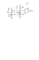
- the figure which shows the structural example of the relay voltage detection circuit shown in FIG. The figure for demonstrating the delta connection state of the electric motor drive device concerning Embodiment 1 of this invention.
- the flowchart of the process which detects the fall of the relay voltage which the motor drive device shown in FIG. 1 performs, and stops an inverter The figure for demonstrating the flow in which the magnet of the motor shown in FIG. 1 does not reach demagnetization.
- Functional block diagram which shows the structure of the air conditioner concerning Embodiment 2 of this invention.
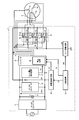
- FIG. 1 is a diagram illustrating a configuration example of an electric motor drive device according to a first embodiment of the present invention.
- the motor drive device 1 according to the present embodiment shown in FIG. 1 generates power for driving the motor 3 from AC power supplied from the AC power supply 2.
- the motor drive device 1 includes an AC (Alternating Current) / DC (Direct Current) converter 11, a smoothing capacitor 12, an inverter 13, a connection state switching unit 14, a DC / A DC converter 19, a relay drive circuit 20, a relay voltage detection circuit 21, an overcurrent cutoff circuit 22, and a control circuit 23 are provided.
- the AC power supply 2 is connected to the input side of the AC / DC converter 11, and the electric motor 3 is connected to the output side of the inverter 13.
- the electric motor 3 is a permanent magnet synchronous motor whose rotor includes a permanent magnet, and is driven by the supply of three-phase AC power from the inverter 13.
- the AC / DC converter 11 converts AC power supplied from the AC power source 2 into DC power.
- the AC / DC converter 11 corresponds to a first voltage converter.
- Smoothing capacitor 12 causes the DC voltage supplied from AC / DC converter 11 to be a constant DC voltage (hereinafter referred to as “smoothing capacitor voltage VDC”).
- the smoothing capacitor voltage VDC is a power supply voltage for the inverter 13.
- the inverter 13 converts the smoothing capacitor voltage VDC into an AC voltage by pulse width modulation, and applies the AC voltage to the electric motor 3 to be driven.
- the inverter 13 includes a stop circuit 24 that stops the inverter 13.
- the inverter 13 corresponds to an inverter unit.
- the electric motor 3 is configured such that both ends of the three stator windings 3u, 3v, 3w are in an open state and the connection state can be changed.
- the connection state switching unit 14 includes relays 15, 16, and 17, and switches the connection state of the stator windings 3 u, 3 v, and 3 w of the electric motor 3 between a star connection state and a delta connection state.
- the delta connection state corresponds to the first connection state.
- the star connection state corresponds to the second connection state.
- the connection state switching unit 14 corresponds to a switching unit.
- Relays 15, 16, and 17 are C contact relays. One terminal is connected to the stator winding, and the other terminal is connected to the first contact or the second contact, and the contact plate is operated. And a coil.
- the relay 15 includes a contact plate 25, contacts 45 and 55, and a coil 35.
- the contact plate 25 is connected to a contact 45 that is a first contact when a current greater than a certain value is not flowing through the coil 35, and is a second contact when a current that is greater than a certain value is flowing through the coil 35. Connected to a certain contact 55.
- the relay 15 is turned off when the contact plate 25 is connected to the contact 45, and the relay 15 is turned on when the contact plate 25 is connected to the contact 55. Since the configuration of the relay 16 and the configuration of the relay 17 are the same as the configuration of the relay 15, description thereof is omitted.
- One terminal of the three stator windings 3u, 3v, 3w of the motor 3 is the three output terminals of the inverter 13, and the other terminal is a contact plate 25, 26, three of the relays 15, 16, 17, 27, respectively.
- the contacts 45, 46 and 47 are each connected to the neutral point terminal 18.
- the contacts 55, 56 and 57 are connected to the three output terminals of the inverter 13, respectively.
- the neutral point terminal 18 is a neutral point when the stator windings 3u, 3v, 3w of the electric motor 3 are star-connected.
- FIG. 1 shows a star connection state.
- the DC / DC converter 19 converts the smoothing capacitor voltage VDC into voltage, and applies the voltage after voltage conversion (hereinafter referred to as “relay voltage VR”) to the coils 35, 36, and 37 included in the relays 15, 16, and 17. .
- the relay voltage VR is a power supply voltage of the connection state switching unit 14 and corresponds to the first power supply voltage.
- the DC / DC converter 19 corresponds to a second voltage conversion unit.
- the relay drive circuit 20 includes a switch, and performs an opening / closing operation of the switch according to the relay drive signal DR received from the control circuit 23. When the switch of the relay drive circuit 20 is closed, current flows through the coils 35, 36, and 37 of the relays 15, 16, and 17.
- the relay voltage detection circuit 21 is connected to the output side of the DC / DC converter 19.
- the relay voltage detection circuit 21 detects the relay voltage VR, and transmits a stop signal D1 for stopping the inverter 13 to the stop circuit 24 when the value of the relay voltage VR is lower than a predetermined threshold value C.
- the threshold value C is set to a voltage value slightly larger than the relay voltage VR at which the relays 15, 16, and 17 cannot be kept on.
- the value of the relay voltage VR at which the relays 15, 16, and 17 cannot be kept on corresponds to the first value.
- the relay voltage detection circuit 21 corresponds to a power supply voltage detection unit.
- FIG. 2 is a diagram showing a configuration example of the relay voltage detection circuit shown in FIG.
- the relay voltage detection circuit 21 divides the relay voltage VR by the resistor 101 and the resistor 102 and inputs the divided voltage V 1 to the negative terminal of the comparator 105.
- the relay voltage detection circuit 21 divides, for example, a voltage V different from the relay voltage VR generated by the DC / DC converter 19 by the resistor 103 and the resistor 104 to generate the reference voltage V2, and the generated reference voltage V2 is compared with the comparator 105. Input to the positive terminal.
- the relay voltage detection circuit 21 configured as described above transmits a Hi signal as the stop signal D1 to the stop circuit 24 when the value of the relay voltage VR is lower than the threshold value C.
- the overcurrent cutoff circuit 22 is branched and connected from the point N between the AC / DC converter 11 and the inverter 13.
- the overcurrent cutoff circuit 22 detects when an excessive current flows in the stator windings 3u, 3v, 3w of the electric motor 3 based on the current I1 flowing through the inverter 13, and detects the stator winding of the electric motor 3. The state where an excessive current flows through the lines 3u, 3v, 3w is eliminated.
- the overcurrent interruption circuit 22 is a permanent magnet that constitutes the rotor when an excessive current exceeding a predetermined value continues to flow in the stator windings 3 u, 3 v, 3 w of the electric motor 3. Prevents demagnetization.
- the overcurrent cut-off circuit 22 performs control to cut off the overcurrent using different current values in the star connection state and the delta connection state.
- the current value at which the magnet of the motor 3 in the star connection state may be demagnetized is greater than the current value at which the magnet of the motor 3 in the delta connection state may be demagnetized. Therefore, the overcurrent cutoff value IS1 in the star connection state is made smaller than the overcurrent cutoff value IS2 in the delta connection.
- the overcurrent cutoff value IS2 corresponds to the first cutoff value.
- the overcurrent cutoff value IS1 corresponds to the second cutoff value.
- the overcurrent cutoff circuit 22 detects that a current larger than the overcurrent cutoff value IS1 or the overcurrent cutoff value IS2 is flowing based on the current flowing through the inverter 13, the overcurrent cutoff circuit 22 A stop signal D2 for stopping 13 is transmitted to the stop circuit 24.
- the control circuit 23 transmits an inverter drive signal DI to the inverter 13 to control each switching element constituting the inverter 13.
- the control circuit 23 transmits a relay drive signal DR to the relay drive circuit 20 in order to switch the connection state of the stator windings 3u, 3v, 3w, and controls on / off of the switch of the relay drive circuit 20.
- the control circuit 23 transmits a cutoff value switching signal DS for switching the overcurrent cutoff value to the overcurrent cutoff circuit 22 in accordance with the connection state of the stator windings 3u, 3v, 3w, and the overcurrent cutoff circuit 22 Controls the switching of the overcurrent cutoff value used for the control to cut off the overcurrent.
- FIG. 3 is a diagram for explaining a delta connection state of the electric motor drive device according to the first exemplary embodiment of the present invention.
- FIG. 4 is a diagram for explaining a flow in which the magnet of the motor shown in FIG. 1 reaches demagnetization.
- the relay voltage VR In the delta connection state shown in FIG. 3, when the smoothing capacitor voltage VDC decreases due to the voltage drop of the AC power supply 2 or the like, the relay voltage VR also decreases, so that a current greater than a certain value does not flow in the coils 35, 36, and 37. There are cases where 15, 16 and 17 are kept on, that is, the delta connection state cannot be maintained.
- the inverter 13 supplies the current supplied in the delta connection state to the electric motor 3 as it is, and the overcurrent cutoff circuit 22 further performs the delta Control is performed to cut off the overcurrent using the overcurrent cut-off value IS2 in the connected state.
- the control circuit 23 can recognize the current connection state, it is possible to transmit the cutoff value switching signal DS for switching the overcurrent cutoff value from the control circuit 23 to the overcurrent cutoff circuit 22.
- the overcurrent cutoff circuit 22 continues to hold the overcurrent cutoff value IS2 in the delta connection state. Therefore, as shown in FIG. 4, the value of the current I1 supplied to the motor 3 may exceed the overcurrent cutoff value IS1 in the star connection state, and the magnet of the motor 3 may be demagnetized. .
- FIG. 5 is a flowchart of a process for detecting a drop in the relay voltage executed by the motor drive device shown in FIG. 1 and stopping the inverter.
- FIG. 6 is a diagram for explaining a flow in which the magnet of the motor shown in FIG. 1 does not reach demagnetization.
- control circuit 23 determines to operate the electric motor 3 in the delta connection state (step S101).
- control circuit 23 transmits a cutoff value switching signal DS for switching the overcurrent cutoff value held by the overcurrent cutoff circuit 22 to the overcurrent cutoff value IS2 in the delta connection state to the overcurrent cutoff circuit 22 ( Step S102).
- the overcurrent cutoff circuit 22 that has received the cutoff value switching signal DS transmitted in step S102 holds the overcurrent cutoff value IS2 in the delta connection state as the overcurrent cutoff value.
- the control circuit 23 transmits a relay drive signal DR for switching the connection state of the stator windings 3u, 3v, 3w to the delta connection state to the relay drive circuit 20 (step S103).
- the relay drive circuit 20 that has received the relay drive signal DR transmitted in step S103 closes the switch, energizes the coils 35, 36, and 37 of the relays 15, 16, and 17, and turns on the relays 15, 16, and 17 Let me.
- control circuit 23 transmits an inverter drive signal DI to the inverter 13 (step S104).
- the inverter 13 that has received the inverter drive signal DI transmitted in step S104 controls each switching element in accordance with the inverter drive signal DI.
- the relay voltage detection circuit 21 detects the relay voltage VR (step S105), and determines whether or not the relay voltage VR is lower than a predetermined threshold C (step S106).
- step S106 If it is determined in step S106 that the relay voltage VR is not lower than the threshold value C (No in step S106), the process returns to step S105.
- step S106 when the relay voltage VR is lower than the threshold value C (Yes in step S106), the relay voltage detection circuit 21 transmits a stop signal D1 to the stop circuit 24 (step S107). .
- the inverter 13 stops and the electric current is supplied to the motor 3 before the delta connection state is switched to the star connection state due to an unexpected voltage drop of the AC power supply 2. It will not be supplied. Thereby, even when the power supply voltage is lowered due to an unexpected voltage drop or the like, the magnet of the electric motor 3 can be prevented from demagnetizing.
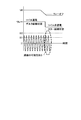
- FIG. 7 is a diagram for explaining a time lag between the smoothing capacitor voltage and the relay voltage in the electric motor driving device shown in FIG.
- the relay voltage VR is detected, it is determined whether or not the relay voltage VR is lower than the threshold value C, and the inverter 13 is stopped.
- the relay voltage VR is generated by converting the smoothing capacitor voltage VDC by the DC / DC converter 19. As shown in FIG. 7, when the smoothing capacitor voltage VDC decreases due to a voltage decrease of the AC power supply 2 or the like, the relay voltage VR does not decrease immediately because it passes through the DC / DC converter 19.
- the relay voltage VR is a detection target, the AC power supply 2 is quickly restored due to an instantaneous voltage drop or the like as compared with the case where the smoothing capacitor voltage VDC is the detection target and the same threshold C is used. In this case, it is possible to increase the possibility that the inverter 13 need not be stopped unnecessarily.
- Embodiment 2 The electric motor drive apparatus according to the first embodiment described above can be applied to an electric motor that operates a compressor or a fan of an air conditioner.
- an air conditioner to which the electric motor drive device described in the first embodiment is applied will be described.
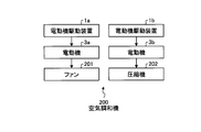
- FIG. 8 is a functional block diagram showing the configuration of the air conditioner according to the second embodiment of the present invention.
- An air conditioner 200 shown in FIG. 8 includes motor drive devices 1a and 1b, a motor 3a driven by the motor drive device 1a, a fan 201 operated by the motor 3a, and a motor 3b driven by the motor drive device 1b. And a compressor 202 operated by the electric motor 3b.
- Electric motor drive devices 1a and 1b are the same as electric motor drive device 1 in the first embodiment, and electric motors 3a and 3b are the same as electric motor 3 in the first embodiment.
- the fan 201 operates by the electric motor 3a to blow air to the air-conditioned space of the air conditioner 200.
- the compressor 202 circulates refrigerant in a refrigerant circuit (not shown) by operating with the electric motor 3b.
- FIG. 8 shows an air conditioner 200 including an electric motor drive device 1a and an electric motor drive device 1b
- the present invention is not limited to this, and the air conditioner 200 may be an electric motor drive device 1a or an electric motor drive.
- the configuration may include only one of the devices 1b.
- the configuration described in the above embodiment shows an example of the contents of the present invention, and can be combined with another known technique, and can be combined with other configurations without departing from the gist of the present invention. It is also possible to omit and change the part.
Landscapes
- Engineering & Computer Science (AREA)
- Power Engineering (AREA)
- Control Of Ac Motors In General (AREA)
- Control Of Electric Motors In General (AREA)
Abstract
Description
まず、本発明の実施の形態1にかかる電動機駆動装置について説明する。図1は、本発明の実施の形態1にかかる電動機駆動装置の構成例を示す図である。図1に示す、本実施の形態にかかる電動機駆動装置1は、交流電源2から供給される交流電力から電動機3を駆動するための電力を生成する。
上述した実施の形態1にかかる電動機駆動装置は、空気調和機の圧縮機またはファンを動作させる電動機に適用することが可能である。本実施の形態では、実施の形態1にて説明した電動機駆動装置を適用した空気調和機について説明する。
Claims (7)
- 電動機の固定子巻線の結線状態を第1の結線状態および第2の結線状態のうちのいずれかに切り替える切替部と、
前記電動機を駆動するインバータ部と、
前記切替部の電源電圧である第1の電源電圧を検知し、前記第1の電源電圧が閾値より低下したときは、前記インバータ部を停止する電源電圧検知部とを備える
電動機駆動装置。 - 前記切替部は、
前記第1の電源電圧が第1の値より小さいときに、前記第2の結線状態側に切り替え、
前記第1の電源電圧が第1の値より大きいときに、前記第1の結線状態側に切り替え、
前記閾値は、前記第1の値より大きい値である
請求項1に記載の電動機駆動装置。 - 前記第1の結線状態は、デルタ結線状態であり、
前記第2の結線状態は、スター結線状態である
請求項1または2に記載の電動機駆動装置。 - 前記固定子巻線が前記第1の結線状態にあるとき、前記インバータ部を流れる電流が第1の遮断値を越えると、前記インバータ部を停止し、
前記固定子巻線が前記第2の結線状態にあるとき、前記インバータ部を流れる電流が、第1の遮断値よりも小さな第2の遮断値を越えると、前記インバータ部を停止する過電流遮断部をさらに備える
請求項1から3のいずれか1項に記載の電動機駆動装置。 - 交流電源から供給される交流電圧を直流電圧に変換して前記インバータ部の電源電圧を生成する第1の電圧変換部と、
前記インバータ部の前記電源電圧を電圧変換して前記第1の電源電圧を生成する第2の電圧変換部とをさらに備える
請求項1から4のいずれか1項に記載の電動機駆動装置。 - 前記インバータ部は、
前記電動機に供給する電力を生成するインバータと、
外部からの停止信号を受信し、前記インバータを停止させる停止回路とを備える
請求項1から5のいずれか1項に記載の電動機駆動装置。 - 請求項1から6のいずれか1項に記載の電動機駆動装置と、
前記電動機駆動装置によって駆動される電動機とを備える
空気調和機。
Priority Applications (5)
| Application Number | Priority Date | Filing Date | Title |
|---|---|---|---|
| US16/955,266 US11177756B2 (en) | 2018-03-08 | 2018-03-08 | Electric motor drive device and air conditioner |
| CN201880090605.0A CN111837332A (zh) | 2018-03-08 | 2018-03-08 | 电动机驱动装置以及空调机 |
| PCT/JP2018/009060 WO2019171549A1 (ja) | 2018-03-08 | 2018-03-08 | 電動機駆動装置および空気調和機 |
| EP18908336.3A EP3764538A4 (en) | 2018-03-08 | 2018-03-08 | ELECTRIC MOTOR AND AIR CONDITIONER DRIVE DEVICE |
| JP2020504599A JP6877627B2 (ja) | 2018-03-08 | 2018-03-08 | 電動機駆動装置および空気調和機 |
Applications Claiming Priority (1)
| Application Number | Priority Date | Filing Date | Title |
|---|---|---|---|
| PCT/JP2018/009060 WO2019171549A1 (ja) | 2018-03-08 | 2018-03-08 | 電動機駆動装置および空気調和機 |
Publications (1)
| Publication Number | Publication Date |
|---|---|
| WO2019171549A1 true WO2019171549A1 (ja) | 2019-09-12 |
Family
ID=67845635
Family Applications (1)
| Application Number | Title | Priority Date | Filing Date |
|---|---|---|---|
| PCT/JP2018/009060 Ceased WO2019171549A1 (ja) | 2018-03-08 | 2018-03-08 | 電動機駆動装置および空気調和機 |
Country Status (5)
| Country | Link |
|---|---|
| US (1) | US11177756B2 (ja) |
| EP (1) | EP3764538A4 (ja) |
| JP (1) | JP6877627B2 (ja) |
| CN (1) | CN111837332A (ja) |
| WO (1) | WO2019171549A1 (ja) |
Families Citing this family (3)
| Publication number | Priority date | Publication date | Assignee | Title |
|---|---|---|---|---|
| US20240128917A1 (en) * | 2021-05-11 | 2024-04-18 | Mitsubishi Electric Corporation | Motor drive device and outdoor unit of air-conditioning apparatus, which includes the same |
| CN115723594A (zh) * | 2021-08-31 | 2023-03-03 | 华为数字能源技术有限公司 | 发射端、接收端、动态无线供电系统及电动汽车 |
| AU2023296082A1 (en) * | 2022-06-17 | 2025-01-02 | Koki Holdings Co., Ltd. | Work machine |
Citations (4)
| Publication number | Priority date | Publication date | Assignee | Title |
|---|---|---|---|---|
| JP2008228513A (ja) * | 2007-03-15 | 2008-09-25 | Mitsubishi Electric Corp | 電動機駆動装置および電動機駆動方法並びに冷凍空調装置 |
| JP2009216324A (ja) | 2008-03-11 | 2009-09-24 | Toshiba Carrier Corp | 空気調和機 |
| JP2014124062A (ja) * | 2012-12-21 | 2014-07-03 | Tsubaki E&M Co | 過負荷検知装置及び過負荷検知方法 |
| JP2015065754A (ja) * | 2013-09-25 | 2015-04-09 | ダイキン工業株式会社 | モータシステム |
Family Cites Families (14)
| Publication number | Priority date | Publication date | Assignee | Title |
|---|---|---|---|---|
| JPS60102893A (ja) * | 1983-11-08 | 1985-06-07 | Hitachi Ltd | 電圧応動形回路自動切替式電動ポンプ |
| EP0528102B1 (en) | 1991-08-20 | 1995-11-08 | Tecumseh Products Company | Protection circuit in inverter for refrigerators |
| US6894455B2 (en) * | 2003-04-30 | 2005-05-17 | Remy Inc. | Performance improvement of integrated starter alternator by changing stator winding connection |
| JP2008022665A (ja) * | 2006-07-14 | 2008-01-31 | Sharp Corp | モータ駆動装置、圧縮機駆動装置及び空調・冷凍装置 |
| US8981696B2 (en) * | 2009-01-16 | 2015-03-17 | International Business Machines Corporation | Dynamic reconfiguration-switching of windings in an electric motor in an electric vehicle |
| JP2010200439A (ja) * | 2009-02-24 | 2010-09-09 | Panasonic Corp | 洗濯機用モータ駆動装置およびこれを用いた洗濯機 |
| CN101718804B (zh) * | 2009-12-04 | 2012-05-23 | 中国电力科学研究院 | 一种用于特高压变压器的局部放电试验电源系统 |
| US8638059B2 (en) | 2010-08-11 | 2014-01-28 | Dayton-Phoenix Group, Inc. | Control for multi-phase induction motor |
| DE102010060380B3 (de) * | 2010-11-05 | 2012-02-02 | Lti Drives Gmbh | Notbetriebsfähige Pitchmotor-Antriebsschaltung |
| JP5565757B2 (ja) * | 2011-04-14 | 2014-08-06 | 株式会社安川電機 | 交流電動機の巻線切替装置及び交流電動機駆動システム |
| CN103863932B (zh) * | 2012-12-17 | 2017-09-05 | 通力股份公司 | 变频器和具有变频器的扶梯控制装置 |
| JP5569606B1 (ja) * | 2013-02-01 | 2014-08-13 | 株式会社安川電機 | インバータ装置および電動機ドライブシステム |
| EP3001548B1 (en) * | 2014-09-29 | 2019-07-03 | Airbus Operations GmbH | Emergency power supply system, aircraft having such an emergency power supply system and a method for providing at least electric power and hydraulic power in case of an emergency in an aircraft |
| US11070157B2 (en) * | 2017-07-21 | 2021-07-20 | Mitsubishi Electric Corporation | Motor drive unit, compressor, and air conditioner |
-
2018
- 2018-03-08 WO PCT/JP2018/009060 patent/WO2019171549A1/ja not_active Ceased
- 2018-03-08 US US16/955,266 patent/US11177756B2/en not_active Expired - Fee Related
- 2018-03-08 CN CN201880090605.0A patent/CN111837332A/zh active Pending
- 2018-03-08 EP EP18908336.3A patent/EP3764538A4/en not_active Withdrawn
- 2018-03-08 JP JP2020504599A patent/JP6877627B2/ja not_active Expired - Fee Related
Patent Citations (4)
| Publication number | Priority date | Publication date | Assignee | Title |
|---|---|---|---|---|
| JP2008228513A (ja) * | 2007-03-15 | 2008-09-25 | Mitsubishi Electric Corp | 電動機駆動装置および電動機駆動方法並びに冷凍空調装置 |
| JP2009216324A (ja) | 2008-03-11 | 2009-09-24 | Toshiba Carrier Corp | 空気調和機 |
| JP2014124062A (ja) * | 2012-12-21 | 2014-07-03 | Tsubaki E&M Co | 過負荷検知装置及び過負荷検知方法 |
| JP2015065754A (ja) * | 2013-09-25 | 2015-04-09 | ダイキン工業株式会社 | モータシステム |
Non-Patent Citations (1)
| Title |
|---|
| See also references of EP3764538A4 * |
Also Published As
| Publication number | Publication date |
|---|---|
| EP3764538A1 (en) | 2021-01-13 |
| JP6877627B2 (ja) | 2021-05-26 |
| US11177756B2 (en) | 2021-11-16 |
| US20210226569A1 (en) | 2021-07-22 |
| EP3764538A4 (en) | 2021-03-03 |
| JPWO2019171549A1 (ja) | 2020-07-02 |
| CN111837332A (zh) | 2020-10-27 |
Similar Documents
| Publication | Publication Date | Title |
|---|---|---|
| JP6636207B2 (ja) | 電動機の駆動装置および冷凍サイクル適用機器 | |
| US10630223B2 (en) | Power tool | |
| CN103296942B (zh) | 具备动态制动控制单元的电动机驱动装置 | |
| JP6622764B2 (ja) | モータの駆動制御装置およびモータの駆動制御方法 | |
| KR20130025921A (ko) | 전력 변환 장치 | |
| JP2009136054A (ja) | 空気調和機の圧縮機用ブラシレスモータ駆動装置 | |
| US20070090783A1 (en) | Method for braking a synchronous machine | |
| JP6704948B2 (ja) | モータの駆動制御装置およびモータの駆動制御方法 | |
| JPWO2019026125A1 (ja) | 電動機駆動装置及び冷凍サイクル適用機器 | |
| JP6877627B2 (ja) | 電動機駆動装置および空気調和機 | |
| JP6727455B2 (ja) | 電動機駆動装置 | |
| JP2011087399A (ja) | 電動機の巻線切替え装置 | |
| WO2019016955A1 (ja) | 電動機駆動装置、圧縮機および空気調和機 | |
| JP2018042297A (ja) | モータ制御装置および空気調和機 | |
| JP2001218476A (ja) | 電動機の制御装置 | |
| KR102564593B1 (ko) | 모터 구동 장치 및 공기 조화기 | |
| JP6012211B2 (ja) | モータ駆動装置とこれを備える空気調和機 | |
| CN111771329B (zh) | 电机的驱动控制装置和电机的驱动控制方法 | |
| JP2018139491A (ja) | 直流電動機駆動装置とそれを搭載した天井埋込型換気装置 | |
| JP6357649B2 (ja) | 直流電動機駆動装置とそれを搭載した天井埋込型換気装置 | |
| KR20110035115A (ko) | 단상 유도 전동기 제어 장치 및 방법 | |
| JP6851495B2 (ja) | 電動機制御装置 |
Legal Events
| Date | Code | Title | Description |
|---|---|---|---|
| 121 | Ep: the epo has been informed by wipo that ep was designated in this application |
Ref document number: 18908336 Country of ref document: EP Kind code of ref document: A1 |
|
| ENP | Entry into the national phase |
Ref document number: 2020504599 Country of ref document: JP Kind code of ref document: A |
|
| NENP | Non-entry into the national phase |
Ref country code: DE |
|
| WWE | Wipo information: entry into national phase |
Ref document number: 2018908336 Country of ref document: EP |
|
| ENP | Entry into the national phase |
Ref document number: 2018908336 Country of ref document: EP Effective date: 20201008 |