WO2019171648A1 - 表面被覆切削工具及びその製造方法 - Google Patents
表面被覆切削工具及びその製造方法 Download PDFInfo
- Publication number
- WO2019171648A1 WO2019171648A1 PCT/JP2018/038491 JP2018038491W WO2019171648A1 WO 2019171648 A1 WO2019171648 A1 WO 2019171648A1 JP 2018038491 W JP2018038491 W JP 2018038491W WO 2019171648 A1 WO2019171648 A1 WO 2019171648A1
- Authority
- WO
- WIPO (PCT)
- Prior art keywords
- layer
- unit layer
- unit
- cutting tool
- coated cutting
- Prior art date
- Legal status (The legal status is an assumption and is not a legal conclusion. Google has not performed a legal analysis and makes no representation as to the accuracy of the status listed.)
- Ceased
Links
Images
Classifications
-
- B—PERFORMING OPERATIONS; TRANSPORTING
- B23—MACHINE TOOLS; METAL-WORKING NOT OTHERWISE PROVIDED FOR
- B23B—TURNING; BORING
- B23B27/00—Tools for turning or boring machines; Tools of a similar kind in general; Accessories therefor
- B23B27/14—Cutting tools of which the bits or tips or cutting inserts are of special material
-
- C—CHEMISTRY; METALLURGY
- C23—COATING METALLIC MATERIAL; COATING MATERIAL WITH METALLIC MATERIAL; CHEMICAL SURFACE TREATMENT; DIFFUSION TREATMENT OF METALLIC MATERIAL; COATING BY VACUUM EVAPORATION, BY SPUTTERING, BY ION IMPLANTATION OR BY CHEMICAL VAPOUR DEPOSITION, IN GENERAL; INHIBITING CORROSION OF METALLIC MATERIAL OR INCRUSTATION IN GENERAL
- C23C—COATING METALLIC MATERIAL; COATING MATERIAL WITH METALLIC MATERIAL; SURFACE TREATMENT OF METALLIC MATERIAL BY DIFFUSION INTO THE SURFACE, BY CHEMICAL CONVERSION OR SUBSTITUTION; COATING BY VACUUM EVAPORATION, BY SPUTTERING, BY ION IMPLANTATION OR BY CHEMICAL VAPOUR DEPOSITION, IN GENERAL
- C23C28/00—Coating for obtaining at least two superposed coatings either by methods not provided for in a single one of groups C23C2/00 - C23C26/00 or by combinations of methods provided for in subclasses C23C and C25C or C25D
- C23C28/04—Coating for obtaining at least two superposed coatings either by methods not provided for in a single one of groups C23C2/00 - C23C26/00 or by combinations of methods provided for in subclasses C23C and C25C or C25D only coatings of inorganic non-metallic material
- C23C28/044—Coating for obtaining at least two superposed coatings either by methods not provided for in a single one of groups C23C2/00 - C23C26/00 or by combinations of methods provided for in subclasses C23C and C25C or C25D only coatings of inorganic non-metallic material coatings specially adapted for cutting tools or wear applications
-
- C—CHEMISTRY; METALLURGY
- C23—COATING METALLIC MATERIAL; COATING MATERIAL WITH METALLIC MATERIAL; CHEMICAL SURFACE TREATMENT; DIFFUSION TREATMENT OF METALLIC MATERIAL; COATING BY VACUUM EVAPORATION, BY SPUTTERING, BY ION IMPLANTATION OR BY CHEMICAL VAPOUR DEPOSITION, IN GENERAL; INHIBITING CORROSION OF METALLIC MATERIAL OR INCRUSTATION IN GENERAL
- C23C—COATING METALLIC MATERIAL; COATING MATERIAL WITH METALLIC MATERIAL; SURFACE TREATMENT OF METALLIC MATERIAL BY DIFFUSION INTO THE SURFACE, BY CHEMICAL CONVERSION OR SUBSTITUTION; COATING BY VACUUM EVAPORATION, BY SPUTTERING, BY ION IMPLANTATION OR BY CHEMICAL VAPOUR DEPOSITION, IN GENERAL
- C23C14/00—Coating by vacuum evaporation, by sputtering or by ion implantation of the coating forming material
- C23C14/02—Pretreatment of the material to be coated
- C23C14/024—Deposition of sublayers, e.g. to promote adhesion of the coating
-
- C—CHEMISTRY; METALLURGY
- C23—COATING METALLIC MATERIAL; COATING MATERIAL WITH METALLIC MATERIAL; CHEMICAL SURFACE TREATMENT; DIFFUSION TREATMENT OF METALLIC MATERIAL; COATING BY VACUUM EVAPORATION, BY SPUTTERING, BY ION IMPLANTATION OR BY CHEMICAL VAPOUR DEPOSITION, IN GENERAL; INHIBITING CORROSION OF METALLIC MATERIAL OR INCRUSTATION IN GENERAL
- C23C—COATING METALLIC MATERIAL; COATING MATERIAL WITH METALLIC MATERIAL; SURFACE TREATMENT OF METALLIC MATERIAL BY DIFFUSION INTO THE SURFACE, BY CHEMICAL CONVERSION OR SUBSTITUTION; COATING BY VACUUM EVAPORATION, BY SPUTTERING, BY ION IMPLANTATION OR BY CHEMICAL VAPOUR DEPOSITION, IN GENERAL
- C23C14/00—Coating by vacuum evaporation, by sputtering or by ion implantation of the coating forming material
- C23C14/06—Coating by vacuum evaporation, by sputtering or by ion implantation of the coating forming material characterised by the coating material
- C23C14/0641—Nitrides
-
- C—CHEMISTRY; METALLURGY
- C23—COATING METALLIC MATERIAL; COATING MATERIAL WITH METALLIC MATERIAL; CHEMICAL SURFACE TREATMENT; DIFFUSION TREATMENT OF METALLIC MATERIAL; COATING BY VACUUM EVAPORATION, BY SPUTTERING, BY ION IMPLANTATION OR BY CHEMICAL VAPOUR DEPOSITION, IN GENERAL; INHIBITING CORROSION OF METALLIC MATERIAL OR INCRUSTATION IN GENERAL
- C23C—COATING METALLIC MATERIAL; COATING MATERIAL WITH METALLIC MATERIAL; SURFACE TREATMENT OF METALLIC MATERIAL BY DIFFUSION INTO THE SURFACE, BY CHEMICAL CONVERSION OR SUBSTITUTION; COATING BY VACUUM EVAPORATION, BY SPUTTERING, BY ION IMPLANTATION OR BY CHEMICAL VAPOUR DEPOSITION, IN GENERAL
- C23C14/00—Coating by vacuum evaporation, by sputtering or by ion implantation of the coating forming material
- C23C14/06—Coating by vacuum evaporation, by sputtering or by ion implantation of the coating forming material characterised by the coating material
- C23C14/0664—Carbonitrides
-
- C—CHEMISTRY; METALLURGY
- C23—COATING METALLIC MATERIAL; COATING MATERIAL WITH METALLIC MATERIAL; CHEMICAL SURFACE TREATMENT; DIFFUSION TREATMENT OF METALLIC MATERIAL; COATING BY VACUUM EVAPORATION, BY SPUTTERING, BY ION IMPLANTATION OR BY CHEMICAL VAPOUR DEPOSITION, IN GENERAL; INHIBITING CORROSION OF METALLIC MATERIAL OR INCRUSTATION IN GENERAL
- C23C—COATING METALLIC MATERIAL; COATING MATERIAL WITH METALLIC MATERIAL; SURFACE TREATMENT OF METALLIC MATERIAL BY DIFFUSION INTO THE SURFACE, BY CHEMICAL CONVERSION OR SUBSTITUTION; COATING BY VACUUM EVAPORATION, BY SPUTTERING, BY ION IMPLANTATION OR BY CHEMICAL VAPOUR DEPOSITION, IN GENERAL
- C23C14/00—Coating by vacuum evaporation, by sputtering or by ion implantation of the coating forming material
- C23C14/06—Coating by vacuum evaporation, by sputtering or by ion implantation of the coating forming material characterised by the coating material
- C23C14/14—Metallic material, boron or silicon
- C23C14/16—Metallic material, boron or silicon on metallic substrates or on substrates of boron or silicon
-
- C—CHEMISTRY; METALLURGY
- C23—COATING METALLIC MATERIAL; COATING MATERIAL WITH METALLIC MATERIAL; CHEMICAL SURFACE TREATMENT; DIFFUSION TREATMENT OF METALLIC MATERIAL; COATING BY VACUUM EVAPORATION, BY SPUTTERING, BY ION IMPLANTATION OR BY CHEMICAL VAPOUR DEPOSITION, IN GENERAL; INHIBITING CORROSION OF METALLIC MATERIAL OR INCRUSTATION IN GENERAL
- C23C—COATING METALLIC MATERIAL; COATING MATERIAL WITH METALLIC MATERIAL; SURFACE TREATMENT OF METALLIC MATERIAL BY DIFFUSION INTO THE SURFACE, BY CHEMICAL CONVERSION OR SUBSTITUTION; COATING BY VACUUM EVAPORATION, BY SPUTTERING, BY ION IMPLANTATION OR BY CHEMICAL VAPOUR DEPOSITION, IN GENERAL
- C23C14/00—Coating by vacuum evaporation, by sputtering or by ion implantation of the coating forming material
- C23C14/22—Coating by vacuum evaporation, by sputtering or by ion implantation of the coating forming material characterised by the process of coating
- C23C14/24—Vacuum evaporation
- C23C14/32—Vacuum evaporation by explosion; by evaporation and subsequent ionisation of the vapours, e.g. ion-plating
- C23C14/325—Electric arc evaporation
-
- C—CHEMISTRY; METALLURGY
- C23—COATING METALLIC MATERIAL; COATING MATERIAL WITH METALLIC MATERIAL; CHEMICAL SURFACE TREATMENT; DIFFUSION TREATMENT OF METALLIC MATERIAL; COATING BY VACUUM EVAPORATION, BY SPUTTERING, BY ION IMPLANTATION OR BY CHEMICAL VAPOUR DEPOSITION, IN GENERAL; INHIBITING CORROSION OF METALLIC MATERIAL OR INCRUSTATION IN GENERAL
- C23C—COATING METALLIC MATERIAL; COATING MATERIAL WITH METALLIC MATERIAL; SURFACE TREATMENT OF METALLIC MATERIAL BY DIFFUSION INTO THE SURFACE, BY CHEMICAL CONVERSION OR SUBSTITUTION; COATING BY VACUUM EVAPORATION, BY SPUTTERING, BY ION IMPLANTATION OR BY CHEMICAL VAPOUR DEPOSITION, IN GENERAL
- C23C28/00—Coating for obtaining at least two superposed coatings either by methods not provided for in a single one of groups C23C2/00 - C23C26/00 or by combinations of methods provided for in subclasses C23C and C25C or C25D
- C23C28/40—Coatings including alternating layers following a pattern, a periodic or defined repetition
- C23C28/42—Coatings including alternating layers following a pattern, a periodic or defined repetition characterized by the composition of the alternating layers
-
- C—CHEMISTRY; METALLURGY
- C23—COATING METALLIC MATERIAL; COATING MATERIAL WITH METALLIC MATERIAL; CHEMICAL SURFACE TREATMENT; DIFFUSION TREATMENT OF METALLIC MATERIAL; COATING BY VACUUM EVAPORATION, BY SPUTTERING, BY ION IMPLANTATION OR BY CHEMICAL VAPOUR DEPOSITION, IN GENERAL; INHIBITING CORROSION OF METALLIC MATERIAL OR INCRUSTATION IN GENERAL
- C23C—COATING METALLIC MATERIAL; COATING MATERIAL WITH METALLIC MATERIAL; SURFACE TREATMENT OF METALLIC MATERIAL BY DIFFUSION INTO THE SURFACE, BY CHEMICAL CONVERSION OR SUBSTITUTION; COATING BY VACUUM EVAPORATION, BY SPUTTERING, BY ION IMPLANTATION OR BY CHEMICAL VAPOUR DEPOSITION, IN GENERAL
- C23C28/00—Coating for obtaining at least two superposed coatings either by methods not provided for in a single one of groups C23C2/00 - C23C26/00 or by combinations of methods provided for in subclasses C23C and C25C or C25D
- C23C28/40—Coatings including alternating layers following a pattern, a periodic or defined repetition
- C23C28/44—Coatings including alternating layers following a pattern, a periodic or defined repetition characterized by a measurable physical property of the alternating layer or system, e.g. thickness, density, hardness
-
- C—CHEMISTRY; METALLURGY
- C23—COATING METALLIC MATERIAL; COATING MATERIAL WITH METALLIC MATERIAL; CHEMICAL SURFACE TREATMENT; DIFFUSION TREATMENT OF METALLIC MATERIAL; COATING BY VACUUM EVAPORATION, BY SPUTTERING, BY ION IMPLANTATION OR BY CHEMICAL VAPOUR DEPOSITION, IN GENERAL; INHIBITING CORROSION OF METALLIC MATERIAL OR INCRUSTATION IN GENERAL
- C23C—COATING METALLIC MATERIAL; COATING MATERIAL WITH METALLIC MATERIAL; SURFACE TREATMENT OF METALLIC MATERIAL BY DIFFUSION INTO THE SURFACE, BY CHEMICAL CONVERSION OR SUBSTITUTION; COATING BY VACUUM EVAPORATION, BY SPUTTERING, BY ION IMPLANTATION OR BY CHEMICAL VAPOUR DEPOSITION, IN GENERAL
- C23C30/00—Coating with metallic material characterised only by the composition of the metallic material, i.e. not characterised by the coating process
- C23C30/005—Coating with metallic material characterised only by the composition of the metallic material, i.e. not characterised by the coating process on hard metal substrates
-
- B—PERFORMING OPERATIONS; TRANSPORTING
- B23—MACHINE TOOLS; METAL-WORKING NOT OTHERWISE PROVIDED FOR
- B23B—TURNING; BORING
- B23B2224/00—Materials of tools or workpieces composed of a compound including a metal
- B23B2224/24—Titanium aluminium nitride
-
- B—PERFORMING OPERATIONS; TRANSPORTING
- B23—MACHINE TOOLS; METAL-WORKING NOT OTHERWISE PROVIDED FOR
- B23B—TURNING; BORING
- B23B2228/00—Properties of materials of tools or workpieces, materials of tools or workpieces applied in a specific manner
- B23B2228/08—Properties of materials of tools or workpieces, materials of tools or workpieces applied in a specific manner applied by physical vapour deposition [PVD]
-
- B—PERFORMING OPERATIONS; TRANSPORTING
- B23—MACHINE TOOLS; METAL-WORKING NOT OTHERWISE PROVIDED FOR
- B23B—TURNING; BORING
- B23B2228/00—Properties of materials of tools or workpieces, materials of tools or workpieces applied in a specific manner
- B23B2228/10—Coatings
- B23B2228/105—Coatings with specified thickness
-
- B—PERFORMING OPERATIONS; TRANSPORTING
- B23—MACHINE TOOLS; METAL-WORKING NOT OTHERWISE PROVIDED FOR
- B23C—MILLING
- B23C5/00—Milling-cutters
- B23C5/16—Milling-cutters characterised by physical features other than shape
Definitions
- the present disclosure relates to a surface-coated cutting tool and a manufacturing method thereof.
- This application claims priority based on Japanese Patent Application No. 2018-040874, which is a Japanese patent application filed on March 7, 2018. All the descriptions described in the Japanese patent application are incorporated herein by reference.
- Patent Document 2 includes an A layer made of a nitride of Al and Cr, and a nitride of Ti and Al for the purpose of performing dry processing with high processing efficiency.
- stacked alternately is disclosed.
- a surface-coated cutting tool comprising a base material and a coating layer covering the base material,
- the coating layer includes alternating layers in which first unit layers and second unit layers are alternately stacked,
- the first unit layer is made of a nitride containing aluminum and zirconium, and the ratio of the number of zirconium atoms when the total number of metal atoms constituting the first unit layer is 1 is 0.65 or more and 0.95 or less.
- the second unit layer is made of a nitride containing titanium and aluminum, and the ratio of the number of aluminum atoms when the total number of metal atoms constituting the second unit layer is 1 is greater than 0.40 and is less than 0.00. It is a surface-coated cutting tool that is 70 or less.
- a method of manufacturing a surface-coated cutting tool according to another aspect of the present disclosure is as follows. [2] A method for producing a surface-coated cutting tool according to [1] above, Preparing the substrate; Forming the alternating layers by alternately laminating the first unit layers and the second unit layers on the substrate using a physical vapor deposition method, and obtaining the surface-coated cutting tool. It is a manufacturing method of the surface coating cutting tool provided.
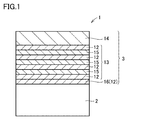
- FIG. 1 is a schematic enlarged cross-sectional view of a surface-coated cutting tool according to an embodiment of the present disclosure.
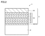
- FIG. 2 is a schematic enlarged cross-sectional view of a surface-coated cutting tool according to another embodiment of the present disclosure.
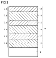
- FIG. 3 is a diagram for explaining an example of the ratio of the thicknesses of the first unit layer and the second unit layer.
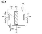
- FIG. 4 is a schematic cross-sectional view of the cathode arc ion plating apparatus used in the examples.
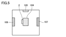
- FIG. 5 is a schematic top view of the cathode arc ion plating apparatus shown in FIG.
- Heat-resistant alloys such as Inconel (registered trademark) used for aircraft engines and the like often contain Cr.
- an object of the present invention is to provide a surface-coated cutting tool that can achieve a long life, especially in the processing of difficult-to-cut materials, and a manufacturing method thereof.
- a surface-coated cutting tool comprising a substrate and a coating layer covering the substrate,
- the coating layer includes alternating layers in which first unit layers and second unit layers are alternately stacked,
- the first unit layer is made of a nitride containing aluminum and zirconium, In the first unit layer, the ratio of the number of zirconium atoms when the total number of metal atoms constituting the first unit layer is 1, is 0.65 or more and 0.95 or less
- the second unit layer is made of a nitride containing titanium and aluminum, In the second unit layer, the ratio of the number of aluminum atoms when the total number of metal atoms constituting the second unit layer is 1 is greater than 0.40 and equal to or less than 0.70. It is.
- Such a surface-coated cutting tool can achieve a long life in processing difficult-to-cut materials.
- the ratio ⁇ 2 / ⁇ 1 of the thickness ⁇ 2 of the second unit layer to the thickness ⁇ 1 of the first unit layer is 1 or more and 5
- the following is preferable. According to this, since the heat dissipation of the entire surface-coated cutting tool is improved, the wear resistance of the surface-coated cutting tool particularly during continuous cutting is improved.
- the first unit layer includes silicon, In the first unit layer, the ratio of the number of silicon atoms when the total number of metal atoms constituting the first unit layer is 1 is preferably greater than 0 and 0.20 or less. According to this, the coating layer can have a high hardness.
- the second unit layer contains silicon, In the second unit layer, the ratio of the number of silicon atoms when the total number of metal atoms constituting the second unit layer is 1 is preferably greater than 0 and 0.20 or less. According to this, the coating layer can have a high hardness.
- the first unit layer includes boron,
- the ratio of the number of boron atoms when the total number of metal atoms constituting the first unit layer is 1 is preferably greater than 0 and less than or equal to 0.10. According to this, the coating layer can have a high hardness.
- the second unit layer contains boron,
- the ratio of the number of boron atoms when the total number of metal atoms constituting the second unit layer is 1 is preferably greater than 0 and less than or equal to 0.10. According to this, the coating layer can have a high hardness.
- the first unit layer includes vanadium, In the first unit layer, the ratio of the number of vanadium atoms when the total number of metal atoms constituting the first unit layer is 1 is preferably greater than 0 and 0.30 or less. According to this, the coating layer can have a high hardness.
- the second unit layer includes vanadium,
- the ratio of the number of vanadium atoms, when the total number of metal atoms constituting the second unit layer is 1, is preferably greater than 0 and 0.30 or less. According to this, the coating layer can have a high hardness.
- each of the first unit layer and the second unit layer has a thickness of 0.002 ⁇ m or more and 0.2 ⁇ m or less. According to this, the progress of cracks can be suppressed.
- the coating layer includes an underlayer disposed between the base material and the alternating layer,
- the underlayer preferably has the same composition as the first unit layer or the second unit layer.
- the base layer has the same composition as the first unit layer, oxidation from the interface between the base material and the coating layer can be suppressed even if the base material is exposed at the initial stage of cutting.
- the underlayer has the same composition as the second unit layer, the peel resistance of the coating layer can be improved in intermittent processing such as milling and end milling.
- the coating layer includes a surface layer disposed on the surface side of the alternating layer,
- the surface layer is made of carbonitride containing titanium and aluminum, and the ratio of the number of aluminum atoms when the total number of metal atoms constituting the surface layer is 1 is larger than 0.40 and not larger than 0.60. It is preferable that According to this, the surface-coated cutting tool can achieve a longer life.
- a method for producing a surface-coated cutting tool according to another aspect of the present disclosure is the method for producing a surface-coated cutting tool according to any one of the above (1) to (11), Preparing the substrate; Forming the alternating layers by alternately laminating the first unit layers and the second unit layers on the substrate using a physical vapor deposition method, and obtaining the surface-coated cutting tool. It is a manufacturing method of the surface coating cutting tool provided.
- the coating layer formed using the physical vapor deposition method has high crystallinity and can have excellent wear resistance. Therefore, the obtained surface-coated cutting tool can achieve a long life.
- any conventionally known atomic ratio is included, and is not necessarily limited to a stoichiometric range.
- ZrAlN the atomic ratio of “Zr (zirconium)”, “Al (aluminum)”, and “N (nitrogen)” is not limited to 25:25:50, and “AlTiN”
- the atomic ratio of “Al”, “Ti (titanium)”, and “N” is not limited to 25:25:50, and any conventionally known atomic ratio is included.
- FIG. 1 is a schematic enlarged cross-sectional view of a surface-coated cutting tool according to an embodiment of the present disclosure.
- FIG. 2 is a schematic enlarged cross-sectional view of a surface-coated cutting tool according to another embodiment of the present disclosure.
- FIG. 3 is a diagram for explaining an example of the ratio of the thicknesses of the first unit layer and the second unit layer.
- a surface-coated cutting tool 1 includes a substrate 2 and a coating layer 3 that covers the substrate 2.
- the coating layer 3 preferably covers the entire surface of the substrate 2, but even if a part of the substrate 2 is not coated with the coating layer 3 or the configuration of the coating layer 3 is partially different, It does not depart from the scope of the embodiment.
- the surface-coated cutting tool of the present embodiment includes a drill, an end mill, a cutting edge replaceable cutting tip for a drill, a cutting edge replaceable cutting tip for an end mill, a cutting edge replaceable cutting tip for milling, a cutting edge replaceable cutting tip for turning, a metal saw, It can be suitably used as a cutting tool such as a gear cutting tool, reamer, or tap.
- any conventionally known base material of this type can be used.
- cemented carbide for example, WC-based cemented carbide, including WC, including Co or containing carbonitride such as Ti, Ta, Nb, etc.
- cermet TiC, TiN, TiCN, etc.
- high-speed steel ceramics (titanium carbide, silicon carbide, silicon nitride, aluminum nitride, aluminum oxide, etc.), cubic boron nitride sintered body, or diamond sintered body preferable.
- a WC-based cemented carbide or cermet particularly TiCN-based cermet. Since these base materials are particularly excellent in the balance between hardness and strength at high temperatures, when used as a base material for a surface-coated cutting tool, it is possible to contribute to extending the life of the surface-coated cutting tool.
- the coating layer 3 included in the surface-coated cutting tool 1 of the present embodiment includes alternating layers 13 in which the first unit layers 12 and the second unit layers 15 are alternately stacked.
- the covering layer 3 can include other layers in addition to the alternating layers 13. Examples of the other layers include an underlayer 16 (ZrAlN, ZrAlSiN, ZrAlBN, ZrAlVN, AlTiSiN, etc.), a surface layer 14 (AlTiCN, AlTiSiCN, AlTiBCN, AlTiVCN, etc.), and the like.
- the coating layer 3 has a function of improving various characteristics such as wear resistance and chipping resistance of the surface-coated cutting tool by coating the base material 2 and extending the life of the surface-coated cutting tool.
- the total thickness of the coating layer is preferably 0.8 ⁇ m or more and 15 ⁇ m or less.
- the coating layer is too thin and the life of the surface-coated cutting tool tends to be shortened.
- the coating layer tends to chip at the beginning of cutting, and the life of the surface-coated cutting tool tends to be shortened.
- the total thickness of the coating layer can be measured by observing the cross section of the coating layer using an SEM (scanning electron microscope).
- the observation magnification of the cross-sectional sample is 5000 to 10,000 times, the observation area is 100 to 500 ⁇ m 2 , three thickness widths are measured in one field of view, and the average value is “thickness”. The same applies to the thickness of each layer described later unless otherwise specified.
- the compressive residual stress of the coating layer is preferably 6 GPa or less in absolute value.
- the compressive residual stress of the coating layer is a kind of internal stress (intrinsic strain) existing in the entire coating layer, and is represented by a numerical value “ ⁇ ” (minus) (unit: “GPa” is used in this embodiment). Stress. For this reason, the concept that the compressive residual stress is large indicates that the absolute value of the numerical value is large, and the concept that the compressive residual stress is small indicates that the absolute value of the numerical value is small. That is, the absolute value of the compressive residual stress being 6 GPa or less means that the preferred residual stress relating to the coating layer is ⁇ 6 GPa or more and 0 GPa or less.
- the residual stress of the coating layer exceeds 0 GPa, it becomes tensile stress, so that it is difficult to suppress the progress of cracks generated from the outermost surface of the coating layer.
- the absolute value of the compressive residual stress exceeds 6 GPa, the stress is too large, and the life of the surface-coated cutting tool may be shortened by peeling the coating layer from the edge portion of the surface-coated cutting tool particularly before the start of cutting. There is.
- Compressive residual stress should be measured by the sin 2 ⁇ method ("X-ray stress measurement method" (Japan Society for Materials Science, published by Yokendo Co., Ltd., 1981), pages 54-66) using an X-ray residual stress device. Can do.
- the crystal structure of the coating layer is preferably cubic.
- the crystal structure of each layer in the coating layer is preferably a cubic type.
- the crystal structure of the coating layer and each layer in the coating layer can be analyzed by an X-ray diffractometer known in the art.
- the hardness of the coating layer is preferably 29 GPa or more and 60 GPa or less, and more preferably 40 GPa or more and 60 GPa or less. According to this, the coating layer has a sufficient hardness.
- the measurement of the hardness of the whole coating layer can be measured by the nano indenter method (Nano Indenter XP made by MTS). Specifically, the hardness of three locations on the surface of the coating layer is measured, and the average value is defined as “hardness”.
- the covering layer 3 includes alternating layers 13 in which the first unit layers 12 and the second unit layers 15 are alternately stacked.
- the first unit layer is made of a nitride containing Al (aluminum) and Zr (zirconium), and the ratio of the number of Zr atoms when the total number of metal atoms constituting the first unit layer is 1 is 0.65 or more and 0. .95 or less.
- the second unit layer is made of a nitride containing Ti (titanium) and Al, and the ratio of the number of Al atoms when the total number of metal atoms constituting the second unit layer is 1 is greater than 0.40 and is less than 0.00. 70 or less.
- the “metal atom” means hydrogen, helium, neon, argon, krypton, xenon, radon, fluorine, chlorine, bromine, iodine, astatine, oxygen, sulfur, selenium, tellurium, nitrogen, phosphorus, arsenic, An atom of an element other than antimony and carbon.
- the composition of each layer including the first unit layer, the second unit layer, the underlayer, the intermediate layer, and the surface layer, and each atom (Zr, Al, Si, B, V with respect to the total number of metal atoms in each layer) )
- XPS X-ray photoelectron spectrometer
- the surface-coated cutting tool of the present embodiment exhibits an excellent effect that a long life can be achieved in processing difficult-to-cut materials. The reason is presumed to be as follows (i) to (vi).
- the first unit layer is made of a nitride containing Al and Zr. Since Al is easily oxidized, a dense oxide layer made of Al 2 O 3 is easily formed on the surface side of the coating layer. Furthermore, since Zr has a lower standard generation energy of oxide than Al, it is more likely to be oxidized than Al, and a dense oxide layer made of ZrO 2 is likely to be formed on the outermost surface of the coating layer. Since these oxide layers improve the oxidation resistance of the coating layer, the surface-coated cutting tool including the coating layer can achieve a long life in processing difficult-to-cut materials.
- the ratio of the number of Zr atoms when the total number of metal atoms constituting the first unit layer is 1 is 0.65 or more and 0.95 or less.
- Mino Mino, "Crystal structure control and properties of pseudo binary nitride hard coating", Journal of High Temperature Society, High Temperature Society, March 2007, Vol. 33, No. 2, p. 50-59
- the crystal structure of the first unit layer becomes cubic, and the hardness is increased and the wear resistance is improved. Therefore, the surface-coated cutting tool including the first unit layer can achieve a long life.
- the second unit layer is made of a nitride containing Ti and Al.
- the layer containing Ti, Al, and N has an excellent balance of wear resistance, oxidation resistance, and toughness. Therefore, the surface-coated cutting tool including the second unit layer can achieve a long life.
- the ratio of the number of Al atoms when the total number of metal atoms constituting the second unit layer is 1 is greater than 0.40 and 0.70 or less.
- the crystal structure of the second unit layer becomes a cubic type, so that the hardness is increased and the wear resistance is improved. Therefore, the surface-coated cutting tool including the second unit layer can achieve a long life.
- This characteristic is complemented by the second unit layer having a high hardness, and the characteristic that the compressive residual stress of the second unit layer is small is supplemented by the first unit layer having a large compressive residual stress. Accordingly, it is considered that the hardness and the compressive residual stress are improved in a balanced manner as a whole of the alternating layers, and the life of the surface-coated cutting tool is further prolonged.
- the alternating layer is formed by alternately laminating the first unit layer and the second unit layer, and the composition and crystal lattice are discontinuous at the interface of each unit layer.
- the first unit layer is made of a nitride containing Al and Zr.
- a layer containing Zr is formed using a physical vapor deposition method, since the melting point of Zr is high, it is difficult to maintain a discharge and it is difficult to form a film stably.
- the melting point of the entire first unit layer is lowered. Therefore, when the first unit layer is formed using a physical vapor deposition method, the discharge can be easily maintained and the film can be stably formed.
- the coating layer of the surface-coated cutting tool of the present embodiment since Zr is expensive, it was disadvantageous in terms of cost to mix it with the coating layer of the surface-coated cutting tool.
- the first unit layer containing Zr and the second unit layer not containing Zr are alternately laminated, so the coating layer is formed as a single layer containing Zr.
- the Zr content in the coating layer can be reduced as compared with the case. Therefore, it is advantageous in terms of cost.
- Zr is not included in difficult-to-cut materials such as Inconel, Zr in the first unit layer does not interdiffuse with components in the work material during processing, and damage to the coating layer is not accelerated.
- the ratio of the number of Zr atoms when the total number of metal atoms constituting the first unit layer is 1 is 0.65 or more and 0.95 or less.
- the crystal structure of the first unit layer becomes a cubic type, and the hardness is increased and the wear resistance is improved.
- the ratio of the number of Zr atoms is less than 0.65, a part of the crystal structure is hexagonal, so that the hardness of the first unit layer may be reduced and the wear resistance may be reduced.
- the ratio of the number of Zr atoms is larger than 0.95, the effect of improving the hardness by adding Al cannot be obtained, and the hardness of the first unit layer is lowered.
- the ratio of the number of Zr atoms is preferably 0.7 or more and 0.85 or less, and more preferably 0.7 or more and 0.8 or less.
- the second unit layer is made of a nitride containing Ti and Al.
- the layer containing Ti, Al, and N has an excellent balance of wear resistance, oxidation resistance, and toughness. Therefore, the second unit layer contributes to the extension of the life of the surface-coated cutting tool.
- the ratio of the number of Al atoms when the total number of metal atoms constituting the second unit layer is 1 is greater than 0.40 and 0.70 or less.
- the crystal structure of the second unit layer becomes a cubic type, so that the hardness is increased and the wear resistance is improved.
- the ratio of the number of Al atoms exceeds 0.7, a part of the crystal structure becomes a hexagonal type, so that the hardness of the second unit layer is lowered and the wear resistance may be lowered.
- the ratio of the number of Al atoms is less than 0.40, the effect of improving the hardness by adding Al cannot be obtained, and the hardness of the second unit layer is lowered.
- the ratio of the number of Al atoms is preferably 0.55 or more and 0.65 or less, and more preferably 0.6 or more and 0.65 or less.
- At least one of the first unit layer and the second unit layer can contain Si (silicon).
- Si silicon
- the ratio of the number of Si atoms in the first unit layer when the total number of metal atoms constituting the first unit layer is 1 is greater than 0 and 0.20 or less.
- the ratio of the number of Si atoms in the second unit layer when the total number of metal atoms constituting the second unit layer is 1 is greater than 0 and is less than 0. 0. It is preferable that it is 20 or less.
- the mechanism is not clear, the hardness of the layer containing Si is further increased, the hardness of the entire coating layer is increased, and the oxidation resistance is improved.
- the Si-containing layer becomes brittle and wear tends to be accelerated.
- an alloy target that is a metal raw material for a layer containing Si is produced by hot isostatic pressing, the alloy target breaks during firing and can be used to form the first unit layer or the second unit layer. It tends to be difficult to obtain a strong material strength.
- the first unit layer or the second unit layer From the viewpoint of increasing the hardness of the first unit layer or the second unit layer and improving the strength of the alloy target, in the first unit layer and / or the second unit layer, the first unit layer or the second unit layer.
- the ratio of the number of Si atoms when the total number of metal atoms constituting the unit layer is 1 is more preferably 0.05 or more and 0.15 or less.
- At least one of the first unit layer and the second unit layer can contain B (boron).
- B boron
- the ratio of the number of B atoms when the total number of metal atoms constituting the first unit layer is 1 is greater than 0 and 0.10 or less. It is preferable.
- the ratio of the number of B atoms in the second unit layer when the total number of metal atoms constituting the second unit layer is 1 is greater than 0 and 0. 10 or less is preferable.
- the hardness of the layer containing B is further increased, and the hardness of the entire coating layer is increased.
- the oxide of B formed by surface oxidation during cutting densifies the oxide of Al in the layer, and the oxidation resistance is improved.
- the oxide of B since the oxide of B has a low melting point, it acts as a lubricant during cutting and can suppress adhesion of the work material.
- the ratio of the number of B atoms when the total number of is 1 is more preferably 0.05 or more and 0.10 or less.
- At least one of the first unit layer and the second unit layer can contain V (vanadium).
- V vanadium
- the ratio of the number of V atoms is greater than 0 and less than or equal to 0.30 when the total number of metal atoms constituting the first unit layer is 1 in the first unit layer. It is preferable that Similarly, when the second unit layer contains V, the ratio of the number of V atoms in the second unit layer when the total number of metal atoms constituting the second unit layer is 1 is greater than 0 and is 0. .30 or less is preferable.
- the oxide of V acts as a lubricant during cutting because of its low melting point, and the work material Can suppress adhesion.
- the first unit layer and / or the second unit layer form the first unit layer or the second unit layer.
- the ratio of the number of V atoms is more preferably greater than 0 and less than 0.15.
- the first unit layer and the second unit layer may contain inevitable impurities other than Al, Zr, and N.
- inevitable impurities include oxygen and carbon.
- the total content of inevitable impurities in each of the first unit layer and the second unit layer is preferably greater than 0 atomic% and less than 1 atomic%.
- “atomic%” means the ratio (%) of the number of atoms to the total number of atoms constituting the layer. The ratio (%) of the number of atoms with respect to the total number of atoms constituting the layer can be measured using the XPS analysis described above.
- the thickness of each of the first unit layer and the second unit layer is 0.002 ⁇ m or more and 0.2 ⁇ m or less. According to this, the progress of cracks generated on the surface of the coating layer can be suppressed.
- the thickness of each of the first unit layer and the second unit layer is less than 0.002 ⁇ m, the respective layers are mixed and tend not to obtain the effect of alternately laminating the first unit layer and the second unit layer. It is in.
- the thickness of each of the first unit layer and the second unit layer exceeds 0.2 ⁇ m, the effect of suppressing the progress of cracks tends to be difficult to obtain.
- the thickness of each of the first unit layer and the second unit layer is more preferably 0.005 ⁇ m or more and 0.15 ⁇ m or less.
- the thickness of the first unit layer in the alternating layer is ⁇ 1
- the thickness of the second unit layer is ⁇ 2
- the adjacent first unit layer and second unit layer in the alternating layer is preferably 1 or more and 5 or less.
- the second unit layer has high thermal conductivity and has the property of easily transferring heat generated during cutting to the substrate. Accordingly, when the proportion of the second unit layer in the coating layer is relatively increased, the heat dissipation performance of the entire surface-coated cutting tool is improved, and in particular, the wear resistance of the surface-coated cutting tool during continuous cutting is improved. . If ⁇ 2 / ⁇ 1 is less than 1, the toughness of the coating layer tends to decrease. On the other hand, when ⁇ 2 / ⁇ 1 exceeds 5, the effect of suppressing the progress of cracks due to the lamination of the first unit layer and the second unit layer tends to be difficult to obtain. From the viewpoint of balance of these characteristics, ⁇ 2 / ⁇ 1 is more preferably 1 or more and less than 3.
- the number of stacked layers of the first unit layer and the second unit layer is preferably 10 or more and 500 or less, and more preferably 100 or more and 400 or less. According to this, by laminating the first unit layer and the second unit layer, it is possible to sufficiently obtain the effect of improving the hardness and the compressive residual stress in a balanced manner.
- the total thickness of the alternating layers is preferably 0.8 ⁇ m or more and 15 ⁇ m or less, and more preferably 2 ⁇ m or more and 7 ⁇ m or less. If the thickness is less than 0.8 ⁇ m, there is a tendency that sufficient wear resistance cannot be exhibited in continuous machining, and if it exceeds 15 ⁇ m, chipping resistance tends to be unstable in intermittent cutting.
- the first unit layer and the second unit layer are alternately laminated to form a multilayer structure.
- the cross section of the coating layer is observed with a TEM (transmission electron microscope), and the difference in contrast is observed. It can be confirmed as showing a multilayer structure.
- the thickness of the first unit layer, the thickness of the second unit layer, the number of stacked layers of the first unit layer and the second unit layer, and the thickness of the alternating layers can be measured using a TEM (transmission electron microscope). It can be measured by observing. Specifically, the measurement can be performed by irradiating an electron beam onto a thinned sample, forming an image of electrons transmitted through the sample or scattered electrons, and observing at high magnification.
- TEM transmission electron microscope
- the coating layer 3 included in the surface-coated cutting tool 1 of the present embodiment can include other layers. Examples of other layers include the underlayer 16 and the surface layer 14. Although not shown in the drawing, the coating layer 3 may further include an intermediate layer or an alumina layer between the alternating layers 13 and the surface layer 14.
- the coating layer 3 can include a base layer 16 between the substrate 2 and the coating layer 3 in order to improve the adhesion between the substrate 2 and the coating layer 3.
- the underlayer 16 preferably has the same composition as the first unit layer 12 or the second unit layer 15.
- the underlayer has the same composition as the first unit layer means that the underlayer has the same composition as the first unit layer included in the alternating layer.
- the underlayer is made of a nitride containing Al and Zr, and the ratio of the number of Zr atoms when the total number of metal atoms constituting the underlayer is 1, is 0.65 or more and 0.95 or less.
- the base layer has the same composition as the first unit layer, oxidation from the interface between the base material and the coating layer can be suppressed even if the base material is exposed in the initial stage of cutting.
- the underlayer having the same composition as that of the first unit layer can contain Si, B, or V, and the content thereof can be the same as that of the first unit layer.
- the ratio of the number of Si atoms when the total number of metal atoms constituting the underlayer is 1 is preferably greater than 0 and 0.10 or less. According to this, the hardness of the underlayer is increased and the crystal structure is also refined, so that the wear resistance is improved.
- the thickness of the underlayer is preferably 0.1 ⁇ m or more. If the thickness of the underlayer is less than 0.1 ⁇ m, the effect of suppressing oxidation from the interface between the substrate and the coating layer due to the same composition as that of the first unit layer tends not to be obtained. .
- the upper limit value of the thickness of the underlayer is not particularly limited. Therefore, in consideration of cost, the thickness of the underlayer is preferably 2 ⁇ m or less.
- the underlayer has the same composition as the first unit layer, and when the alternating layer is formed on the underlayer, the first unit of the alternating layer is formed directly on the underlayer having the same composition as the first unit layer.
- Layers may be stacked (FIG. 1), or the second unit layer may be stacked.
- the underlayer has the same composition as the first unit layer, and the first unit layer of the alternating layer is laminated directly on the underlayer, the underlayer and the first unit layer of the alternating layer are continuous. Since it has a crystal structure, it substantially exists as a layer composed of a single layer of nitride containing Al and Zr.
- the thickness of the layer made of nitride containing Al and Zr immediately above the base is larger than the thickness of the other first unit layer in the alternating layer, the same composition as the first unit layer is obtained. It is understood that the underlying layer and the first unit layer closest to the base material of the alternating layers are continuously present. In this case, the thickness ⁇ 1 of the first unit layer is the thickness of the first unit layer other than the first unit layer continuous with the base layer.
- the underlayer has the same composition as the second unit layer means that the underlayer has the same composition as the second unit layer included in the alternating layer.
- the underlayer is made of a nitride containing Ti and Al, and the ratio of the number of Al atoms when the total number of metal atoms constituting the underlayer is 1 is greater than 0.40 and less than or equal to 0.70. is there.
- the second unit layer tends to have a low stress. Therefore, in intermittent processing such as milling and end milling where the load is repeatedly applied to the cutting edge, the coating layer
- the peel resistance of the resin is greatly improved. From the viewpoint of improving the peel resistance, the ratio of the number of Al atoms is preferably greater than 0.50 and less than or equal to 0.65 when the total number of metal atoms constituting the underlayer is 1.
- the underlayer having the same composition as that of the second unit layer can contain Si, B, or V, and the content thereof can be the same as that of the second unit layer.
- the thickness of the underlayer is preferably 0.1 ⁇ m or more.
- the thickness of the underlayer is less than 0.1 ⁇ m, it tends to be impossible to obtain the effect of improving the peel resistance by setting the underlayer to the same composition as the second unit layer.
- the upper limit value of the thickness of the underlayer is not particularly limited, but if it exceeds 2 ⁇ m, further improvement in the above-mentioned peel resistance tends not to be recognized. Therefore, in consideration of cost, the thickness of the underlayer is preferably 2 ⁇ m or less.
- the underlayer has the same composition as the second unit layer, and when the alternating layer is formed on the underlayer, the first unit of the alternating layer is formed directly on the underlayer having the same composition as the second unit layer.
- a layer may be laminated (FIG. 2), or a second unit layer may be laminated.
- the underlayer and the second unit layer of the alternating layer are continuous. Since it has a crystal structure, it substantially exists as a layer composed of a single layer of nitride containing Ti and Al.
- the thickness of the layer made of nitride containing Ti and Al immediately above the substrate is larger than the thickness of the other second unit layer in the alternating layer, the same composition as the second unit layer is obtained. It is understood that the underlying layer and the second unit layer closest to the base material of the alternating layers are continuously present. In this case, the thickness ⁇ 2 of the second unit layer is the thickness of the second unit layer other than the second unit layer continuous with the base layer.
- the coating layer 3 can include a surface layer 14 on the surface side of the alternating layer 13 in order to reduce the friction coefficient of the coating layer 3 and extend the life of the surface-coated cutting tool.
- the surface layer is made of a carbonitride (compound containing carbon and nitrogen) containing Ti and Al, and the ratio of the number of Al atoms when the total number of metal atoms constituting the surface layer is 1 is more than 0.40. It is preferably 0.60 or less.
- carbonitride tends to have a lower coefficient of friction against the work material than nitride. Such a decrease in the friction coefficient is thought to be due to the contribution of carbon atoms.
- the coating layer includes a surface layer, the coefficient of friction of the coating layer with respect to the work material decreases, and the life of the surface-coated cutting tool is extended.
- carbonitrides containing Ti and Al have excellent oxidation resistance.
- the surface of the surface layer has the highest temperature compared to the surfaces of the other layers during cutting, but has a superior oxidation resistance, so that the surface-coated cutting tool has a long life.
- the ratio of the number of Al atoms when the total number of metal atoms constituting the surface layer is 1 is more preferably 0.50 or more and 0.60 or less.
- the surface layer can contain Si, and the ratio of the number of Si atoms when the total number of metal atoms constituting the surface layer is 1 is preferably greater than 0 and not greater than 0.20, and not less than 0.05 and not greater than 0.15 The following is more preferable. According to this, the hardness of the surface layer is increased and the oxidation resistance is improved.
- the surface layer can contain B, and the ratio of the number of B atoms when the total number of metal atoms constituting the surface layer is 1, is preferably greater than 0 and less than 0.10, greater than 0 and greater than 0.05. The following is more preferable. According to this, the hardness of the surface layer is increased. Further, the B oxide formed by surface oxidation during cutting tends to densify the Al oxide in the layer, and the oxidation resistance is improved.
- the surface layer can contain V, and the ratio of the number of V atoms when the total number of metal atoms constituting the surface layer is 1 is preferably greater than 0 and less than or equal to 0.30, more preferably greater than 0 and less than 0.15 Less than is more preferable. According to this, the adhesion resistance of the surface layer is improved.
- the thickness of the surface layer is preferably 0.1 ⁇ m or more.
- the thickness of the surface layer is less than 0.1 ⁇ m, it may be difficult to obtain the lubricity imparting effect by the surface layer.
- the upper limit value of the thickness of the surface layer is not particularly limited, but if it exceeds 2 ⁇ m, the above-described lubricity imparting effect tends not to be further improved. Therefore, considering the cost, the thickness of the surface layer is preferably 2 ⁇ m or less.
- the method for manufacturing a surface-coated cutting tool according to an embodiment of the present disclosure described above includes a step of preparing a base material, and a first unit layer and a second unit layer on the base material using a physical vapor deposition method. Forming alternating layers by alternately stacking and obtaining a surface-coated cutting tool.
- alternating layers are formed by alternately laminating the first unit layer and the second unit layer using a physical vapor deposition method (PVD method) on the substrate, and according to an embodiment of the present disclosure A surface-coated cutting tool is obtained.
- PVD method physical vapor deposition method
- a base layer can be formed immediately above the base material in order to improve the adhesion between the base material and the coating layer.
- the physical vapor deposition method at least one selected from the group consisting of a cathode arc ion plating method, a balanced magnetron sputtering method, an unbalanced magnetron sputtering method, and a HiPIMS method can be used.
- a cathode arc ion plating method in which the ionization rate of the raw material elements is high.
- a metal ion bombardment treatment can be performed on the surface of the base material before forming the alternating layers. Is significantly improved.
- a base material is set in the apparatus and a target is set as a cathode, and then a high voltage is applied to the target to generate an arc discharge to ionize atoms constituting the target.
- a high voltage is applied to the target to generate an arc discharge to ionize atoms constituting the target.
- a base is set in the apparatus and a target is set on a magnetron electrode having a magnet that forms a balanced magnetic field, and high-frequency power is applied between the magnetron electrode and the base. Then, gas plasma is generated, ions of the gas generated by the generation of the gas plasma collide with the target, and atoms emitted from the target can be deposited on the substrate.
- the unbalanced magnetron sputtering method can be performed, for example, by making the magnetic field generated by the magnetron electrode in the balanced magnetron sputtering method unbalanced. Furthermore, the HiPIMS method that can apply a high voltage and obtain a dense film can also be used.
- other layers such as an intermediate layer, an alumina layer, and a surface layer can be formed on the alternating layers.
- These other layers can be formed by a conventionally known chemical vapor deposition method or physical vapor deposition method. From the viewpoint that other layers can be continuously formed with the first unit layer and the second unit layer in one physical vapor deposition apparatus, the other layers are preferably formed by physical vapor deposition.
- FIG. 4 is a schematic cross-sectional view of the cathode arc ion plating apparatus used in this example, and FIG. 5 is a schematic top view of the apparatus of FIG.
- a first unit layer cathode 106, a second unit layer cathode 107, and a surface layer cathode 120, which are alloy targets that are metal raw materials for the coating layer, are provided in the chamber 101.
- a rotary base material holder 104 for installing the base material 2 is attached.
- An arc power source 108 is attached to the cathode 106, and an arc power source 109 is attached to the cathode 107.
- a bias power source 110 is attached to the substrate holder 104.
- a gas inlet for introducing the gas 105 is provided in the chamber 101, and a gas outlet 103 is provided for adjusting the pressure in the chamber 101.
- the chamber 101 is evacuated from the gas outlet 103 by a vacuum pump. The gas in the gas 101 can be sucked.
- the base holder 104 was equipped with a chip made of cemented carbide of grade JIS standard P30 and having a shape of CNMG120408 and SEMT13T3AGSN manufactured by Sumitomo Electric Hardmetal Co., Ltd. as the base material 2.
- the inside of the chamber 101 is depressurized by a vacuum pump, and the temperature in the chamber 101 is heated to 500 ° C. by a heater installed in the apparatus while rotating the base material 2 so that the pressure in the chamber 101 is 1.0 ⁇ 10 ⁇ 4. Vacuuming was performed until Pa was reached.
- argon gas is introduced from the gas inlet, the pressure in the chamber 101 is maintained at 3.0 Pa, the voltage of the bias power supply 110 is gradually increased to ⁇ 1000 V, and the surface of the substrate 2 is cleaned for 15 minutes. I did it. Thereafter, the base material was cleaned by exhausting argon gas from the chamber 101 (argon bombardment treatment).
- the metal ions are generated from the cathodes 106 and 107 by supplying the arc current of 100 A to the cathodes 106 and 107 respectively while maintaining the voltage of 110 at a certain constant value in the range of ⁇ 50V to ⁇ 200V.
- An underlayer and alternating layers having the composition shown in Table 1 were formed above.
- the composition of the cathode 106 is adjusted so that the ratio of Zr, Al, Si, B, and V is the same as the composition ratio of the first unit layer in Table 1.
- the composition of the cathode 107 is adjusted so that the ratio of Al, Ti, Si, B, and V is the same as the composition ratio of the second unit layer in Table 1.
- the alternating layers were formed by alternately laminating the first unit layer and the second unit layer one by one on the underlayer, and laminating the number of layers shown in Table 1. Moreover, the thickness of the foundation layer, the thickness of each of the first unit layer and the second unit layer in the alternating layers, and the number of layers were adjusted by the rotation speed of the base material. Then, the current supplied to the evaporation source was stopped when the thicknesses of the underlayer and the alternating layer reached the thicknesses shown in Table 1, respectively.
- the cathode 120 is maintained while maintaining the temperature of the substrate 2 at 400 ° C., the reaction gas pressure at 2.0 Pa, and the bias power supply 110 at ⁇ 350V.
- the arc current of 100 A to generate metal ions from the cathode 120 to form a surface layer on the alternating layers.
- the current supplied to the evaporation source was stopped.
- the composition of the cathode 120 is adjusted so that the ratio of Al, Ti, Si, B, and V is the same as the composition ratio of the surface layer in Table 1.
- the ratio of nitrogen and carbon in the composition of the surface layer was adjusted by the ratio between the amount of nitrogen introduced and the amount of methane gas introduced. As a result, the cutting edge exchangeable cutting tips of Samples 1 to 3, 6 to 15, 17, 18, 21, 22, and 24 were produced.
- sample 19 only the second unit layer having the composition shown in Table 1 is formed on the same substrate as that of sample 1, and the base layer, the first unit layer, and the surface layer are not formed. A chip was fabricated.
- compositions of the underlayer, the first unit layer, the second unit layer, and the surface layer in Table 1 were measured using XPS (X-ray photoelectron spectrometer).
- one layer thickness means the thickness of each of the first unit layer and the second unit layer constituting the alternating layers.
- Thiickness in Table 1 means the total thickness of each of the underlayer, the first unit layer, the second unit layer, the surface layer, and the coating layer.
- One layer thickness” and “thickness” are values measured using TEM and SEM, respectively.
- the number of stacked layers in Table 1 means the number of layers of the first unit layer and the second unit layer in the alternating layers.
- the “hardness of the entire coating layer” in Table 1 is a value confirmed by a nano indenter (Nano Indenter XP manufactured by MTS).
- the “compressive residual stress of the entire coating layer” in Table 1 is the value of the sin 2 ⁇ method (“X-ray stress measurement method” (Japan Society for Materials Science, published by Yokendo Co., Ltd. in 1981) using an X-ray residual stress measurement device. (See pages 54 to 66).
- the “crystallinity of the entire coating layer” in Table 1 is analyzed by an X-ray diffractometer. ⁇ Life evaluation of surface-coated cutting tools> (Turning test) For each of the CNMG120408 shaped cutting edge exchangeable cutting tips of Samples 1 to 24, a wet continuous turning test and an intermittent turning test were performed on the alloy steel and the difficult-to-cut material under the conditions shown in Table 2, and the flank wear amount of the cutting edge was measured to reach 0.2 mm. The results are shown in Table 3. In Table 3, the longer the cutting time, the longer the life.
- the cutting edge replaceable cutting tips of Samples 1 to 16, 23, and 24 correspond to the examples, and the cutting edge replaceable cutting tips of Samples 17 to 22 correspond to the comparative example.
- Samples 1-16, 23, and 24 have significantly reduced flank wear on the cutting edge in both continuous and intermittent turning tests compared to Samples 17-22, and high-speed and high-efficiency machining of difficult-to-cut materials Also, it was confirmed that the life of the blade-tip-exchangeable cutting tip was significantly increased.
- the cutting edge replaceable cutting tips of Samples 1 to 16, 23, and 24 correspond to the examples, and the cutting edge replaceable cutting tips of Samples 17 to 22 correspond to the comparative example.
- Samples 1-16, 23, and 24 have a significantly increased cutting length of the cutting edge compared to Samples 17 to 22, and the cutting edge replaceable cutting tip has a long service life even in high-speed and high-efficiency milling. It was confirmed that it would be significantly longer.
Landscapes
- Chemical & Material Sciences (AREA)
- Engineering & Computer Science (AREA)
- Mechanical Engineering (AREA)
- Chemical Kinetics & Catalysis (AREA)
- Materials Engineering (AREA)
- Metallurgy (AREA)
- Organic Chemistry (AREA)
- Inorganic Chemistry (AREA)
- Cutting Tools, Boring Holders, And Turrets (AREA)
- Drilling Tools (AREA)
- Physical Vapour Deposition (AREA)
Abstract
基材と、前記基材を被覆する被覆層とを含む表面被覆切削工具であって、前記被覆層は、第1単位層と第2単位層とが交互に積層された交互層を含み、前記第1単位層はアルミニウム及びジルコニウムを含む窒化物からなり、前記第1単位層において、前記第1単位層を構成する金属原子の総数を1としたときの前記ジルコニウムの原子数の比は0.65以上0.95以下であり、前記第2単位層はチタン及びアルミニウムを含む窒化物からなり、前記第2単位層において、前記第2単位層を構成する金属原子の総数を1としたときの前記アルミニウムの原子数の比は0.40よりも大きく0.70以下である。
Description
本開示は、表面被覆切削工具及びその製造方法に関する。本出願は、2018年3月7日に出願した日本特許出願である特願2018-040874号に基づく優先権を主張する。当該日本特許出願に記載された全ての記載内容は、参照によって本明細書に援用される。
近年、地球環境保全の観点から切削油剤を用いないドライ加工が求められていること、加工能率を向上させるために切削速度がより高速になってきていること、及び被削材が多様化しており特に航空機や医療の分野では難削材と呼ばれる耐熱合金等の切削が増えていること、等の理由から、切削工程における表面被覆切削工具の刃先温度が高温になる傾向にある。刃先温度が高温になると、表面被覆切削工具の寿命が短くなってしまう。従って、このような過酷な切削条件下においても、優れた工具寿命を示すことのできる表面被覆切削工具が求められている。
例えば、特開2003-34859号公報(特許文献1)には、高速・高能率切削における切削工具の耐摩耗性を向上することを目的として、(Alb,[Cr1-eVe]c)(C1-dNd)の組成(ただし、0.5≦b≦0.8、0.2≦c≦0.5、b+c=1、0.05≦e≦0.95、0.5≦d≦1)または(Ma,Alb,[Cr1-eVe]c)(C1-dNd)の組成(ただし、MはTi、Nb、W、TaおよびMoよりなる群から選択された少なくとも1種であり、0.02≦a≦0.3、0.5≦b≦0.8、0.05≦c、a+b+c=1、0.5≦d≦1、0≦e≦1)からなる被覆層が開示されている。
また、国際公開2006/070730号(特許文献2)には、ドライ加工を高加工能率で行うことを目的として、AlとCrとの窒化物からなるA層と、TiとAlとの窒化物からなるB層とが交互に積層された交互層を含む被覆層が開示されている。
本開示の一態様に係る表面被覆切削工具は、
[1]基材と、前記基材を被覆する被覆層とを含む表面被覆切削工具であって、
前記被覆層は、第1単位層と第2単位層とが交互に積層された交互層を含み、
前記第1単位層はアルミニウム及びジルコニウムを含む窒化物からなり、前記第1単位層を構成する金属原子の総数を1としたときの前記ジルコニウムの原子数の比は0.65以上0.95以下であり、
前記第2単位層はチタン及びアルミニウムを含む窒化物からなり、前記第2単位層を構成する金属原子の総数を1としたときの前記アルミニウムの原子数の比は0.40よりも大きく0.70以下である、表面被覆切削工具である。
[1]基材と、前記基材を被覆する被覆層とを含む表面被覆切削工具であって、
前記被覆層は、第1単位層と第2単位層とが交互に積層された交互層を含み、
前記第1単位層はアルミニウム及びジルコニウムを含む窒化物からなり、前記第1単位層を構成する金属原子の総数を1としたときの前記ジルコニウムの原子数の比は0.65以上0.95以下であり、
前記第2単位層はチタン及びアルミニウムを含む窒化物からなり、前記第2単位層を構成する金属原子の総数を1としたときの前記アルミニウムの原子数の比は0.40よりも大きく0.70以下である、表面被覆切削工具である。
本開示の他の一態様に係る表面被覆切削工具の製造方法は、
[2]上記[1]に記載の表面被覆切削工具の製造方法であって、
前記基材を準備する工程と、
前記基材上に、物理的蒸着法を用いて前記第1単位層と前記第2単位層とを交互に積層することにより前記交互層を形成し、前記表面被覆切削工具を得る工程と、を備える、表面被覆切削工具の製造方法である。
[2]上記[1]に記載の表面被覆切削工具の製造方法であって、
前記基材を準備する工程と、
前記基材上に、物理的蒸着法を用いて前記第1単位層と前記第2単位層とを交互に積層することにより前記交互層を形成し、前記表面被覆切削工具を得る工程と、を備える、表面被覆切削工具の製造方法である。
[本開示が解決しようとする課題]
航空機のエンジン等に用いられるインコネル(登録商標)等に代表される耐熱合金は、Crを含有する場合が多い。上述の特許文献1及び特許文献2の被覆層はCrを含む。従って、これらの切削工具を用いて耐熱合金を切削した場合、被覆層中のCrと被削材中のCrとが相互拡散して、被覆層の損傷が加速されることが技術的な問題となっている。
航空機のエンジン等に用いられるインコネル(登録商標)等に代表される耐熱合金は、Crを含有する場合が多い。上述の特許文献1及び特許文献2の被覆層はCrを含む。従って、これらの切削工具を用いて耐熱合金を切削した場合、被覆層中のCrと被削材中のCrとが相互拡散して、被覆層の損傷が加速されることが技術的な問題となっている。
そこで、本目的は、特に難削材の加工においても、長寿命を達成することができる表面被覆切削工具及びその製造方法を提供することを目的とする。
[本開示の効果]
上記態様によれば、特に難削材の加工においても、長寿命を達成することができる表面被覆切削工具及びその製造方法を提供することが可能となる。
[本開示の効果]
上記態様によれば、特に難削材の加工においても、長寿命を達成することができる表面被覆切削工具及びその製造方法を提供することが可能となる。
[本開示の実施形態の説明]
最初に本開示の実施態様を列記して説明する。
最初に本開示の実施態様を列記して説明する。
本開示の一態様に係る表面被覆切削工具は、
(1) 基材と、前記基材を被覆する被覆層とを含む表面被覆切削工具であって、
前記被覆層は、第1単位層と第2単位層とが交互に積層された交互層を含み、
前記第1単位層はアルミニウム及びジルコニウムを含む窒化物からなり、
前記第1単位層において、前記第1単位層を構成する金属原子の総数を1としたときの前記ジルコニウムの原子数の比は0.65以上0.95以下であり、
前記第2単位層はチタン及びアルミニウムを含む窒化物からなり、
前記第2単位層において、前記第2単位層を構成する金属原子の総数を1としたときの前記アルミニウムの原子数の比は0.40よりも大きく0.70以下である、表面被覆切削工具である。
(1) 基材と、前記基材を被覆する被覆層とを含む表面被覆切削工具であって、
前記被覆層は、第1単位層と第2単位層とが交互に積層された交互層を含み、
前記第1単位層はアルミニウム及びジルコニウムを含む窒化物からなり、
前記第1単位層において、前記第1単位層を構成する金属原子の総数を1としたときの前記ジルコニウムの原子数の比は0.65以上0.95以下であり、
前記第2単位層はチタン及びアルミニウムを含む窒化物からなり、
前記第2単位層において、前記第2単位層を構成する金属原子の総数を1としたときの前記アルミニウムの原子数の比は0.40よりも大きく0.70以下である、表面被覆切削工具である。
このような表面被覆切削工具は、難削材の加工において、長寿命を達成することができる。
(2)前記交互層中の隣り合う前記第1単位層と前記第2単位層とにおいて、前記第1単位層の厚みλ1に対する前記第2単位層の厚みλ2の比λ2/λ1は1以上5以下であることが好ましい。これによると、表面被覆切削工具全体としての放熱性が向上するので、特に、連続切削時の表面被覆切削工具の耐摩耗性が向上する。
(3)前記第1単位層は珪素を含み、
前記第1単位層において、前記第1単位層を構成する金属原子の総数を1としたときの前記珪素の原子数の比は0よりも大きく0.20以下であることが好ましい。これによると、被覆層は高い硬度を有することができる。
前記第1単位層において、前記第1単位層を構成する金属原子の総数を1としたときの前記珪素の原子数の比は0よりも大きく0.20以下であることが好ましい。これによると、被覆層は高い硬度を有することができる。
(4)前記第2単位層は珪素を含み、
前記第2単位層において、前記第2単位層を構成する金属原子の総数を1としたときの前記珪素の原子数の比は0よりも大きく0.20以下であることが好ましい。これによると、被覆層は高い硬度を有することができる。
前記第2単位層において、前記第2単位層を構成する金属原子の総数を1としたときの前記珪素の原子数の比は0よりも大きく0.20以下であることが好ましい。これによると、被覆層は高い硬度を有することができる。
(5)前記第1単位層は硼素を含み、
前記第1単位層において、前記第1単位層を構成する金属原子の総数を1としたときの前記硼素の原子数の比は0よりも大きく0.10以下であることが好ましい。これによると、被覆層は高い硬度を有することができる。
前記第1単位層において、前記第1単位層を構成する金属原子の総数を1としたときの前記硼素の原子数の比は0よりも大きく0.10以下であることが好ましい。これによると、被覆層は高い硬度を有することができる。
(6)前記第2単位層は硼素を含み、
前記第2単位層において、前記第2単位層を構成する金属原子の総数を1としたときの前記硼素の原子数の比は0よりも大きく0.10以下であることが好ましい。これによると、被覆層は高い硬度を有することができる。
前記第2単位層において、前記第2単位層を構成する金属原子の総数を1としたときの前記硼素の原子数の比は0よりも大きく0.10以下であることが好ましい。これによると、被覆層は高い硬度を有することができる。
(7)前記第1単位層はバナジウムを含み、
前記第1単位層において、前記第1単位層を構成する金属原子の総数を1としたときの前記バナジウムの原子数の比は0よりも大きく0.30以下であることが好ましい。これによると、被覆層は高い硬度を有することができる。
前記第1単位層において、前記第1単位層を構成する金属原子の総数を1としたときの前記バナジウムの原子数の比は0よりも大きく0.30以下であることが好ましい。これによると、被覆層は高い硬度を有することができる。
(8)前記第2単位層はバナジウムを含み、
前記第2単位層において、前記第2単位層を構成する金属原子の総数を1としたときの前記バナジウムの原子数の比は0よりも大きく0.30以下であることが好ましい。これによると、被覆層は高い硬度を有することができる。
前記第2単位層において、前記第2単位層を構成する金属原子の総数を1としたときの前記バナジウムの原子数の比は0よりも大きく0.30以下であることが好ましい。これによると、被覆層は高い硬度を有することができる。
(9)前記第1単位層及び前記第2単位層は、それぞれ1層の厚みが0.002μm以上0.2μm以下であることが好ましい。これによると、クラックの進展を抑制することができる。
(10)前記被覆層は前記基材と前記交互層との間に配置される下地層を含み、
前記下地層は、前記第1単位層又は前記第2単位層と同一の組成を有することが好ましい。
前記下地層は、前記第1単位層又は前記第2単位層と同一の組成を有することが好ましい。
下地層が第1単位層と同一の組成を有する場合は、切削初期に基材が露出したとしても、基材と被覆層との界面からの酸化を抑制することができる。下地層が第2単位層と同一の組成を有する場合は、フライス加工やエンドミル加工等の断続加工の場合において、被覆層の耐剥離性を向上することができる。
(11)前記被覆層は前記交互層の表面側に配置される表面層を含み、
前記表面層は、チタン及びアルミニウムを含む炭窒化物からなり、前記表面層を構成する金属原子の総数を1としたときの前記アルミニウムの原子数の比は0.40よりも大きく0.60以下であることが好ましい。これによると、表面被覆切削工具は、より長寿命を達成することができる。
前記表面層は、チタン及びアルミニウムを含む炭窒化物からなり、前記表面層を構成する金属原子の総数を1としたときの前記アルミニウムの原子数の比は0.40よりも大きく0.60以下であることが好ましい。これによると、表面被覆切削工具は、より長寿命を達成することができる。
(12)本開示の他の一態様に係る表面被覆切削工具の製造方法は、上記(1)~(11)のいずれかに記載の表面被覆切削工具の製造方法であって、
前記基材を準備する工程と、
前記基材上に、物理的蒸着法を用いて前記第1単位層と前記第2単位層とを交互に積層することにより前記交互層を形成し、前記表面被覆切削工具を得る工程と、を備える、表面被覆切削工具の製造方法である。
前記基材を準備する工程と、
前記基材上に、物理的蒸着法を用いて前記第1単位層と前記第2単位層とを交互に積層することにより前記交互層を形成し、前記表面被覆切削工具を得る工程と、を備える、表面被覆切削工具の製造方法である。
物理的蒸着法を用いて形成された被覆層は、結晶性が高く、優れた耐摩耗性を有することができる。従って、得られた表面被覆切削工具は、長寿命を達成することができる。
[本開示の実施形態の詳細]
本開示の一実施形態にかかる表面被覆切削工具の具体例を、以下に図面を参照しつつ説明する。
本開示の一実施形態にかかる表面被覆切削工具の具体例を、以下に図面を参照しつつ説明する。
本明細書において化合物を化学式で表わす場合、原子比を特に限定しない場合は従来公知のあらゆる原子比を含むものとし、必ずしも化学量論的範囲のもののみに限定されるものではない。例えば単に「ZrAlN」と記す場合、「Zr(ジルコニウム)」と「Al(アルミニウム)」と「N(窒素)」の原子比は25:25:50の場合のみに限られず、また「AlTiN」と記す場合も「Al」と「Ti(チタン)」と「N」の原子比は25:25:50の場合のみに限られず、従来公知のあらゆる原子比が含まれるものとする。
<表面被覆切削工具>
本開示の一実施の形態に係る表面被覆切削工具について、図1~図3を用いて説明する。図1は、本開示の一実施の形態に係る表面被覆切削工具の模式的な拡大断面図である。図2は、本開示の他の一実施の形態に係る表面被覆切削工具の模式的な拡大断面図である。図3は、第1単位層及び第2単位層の厚みの比の一例を説明するための図である。
本開示の一実施の形態に係る表面被覆切削工具について、図1~図3を用いて説明する。図1は、本開示の一実施の形態に係る表面被覆切削工具の模式的な拡大断面図である。図2は、本開示の他の一実施の形態に係る表面被覆切削工具の模式的な拡大断面図である。図3は、第1単位層及び第2単位層の厚みの比の一例を説明するための図である。
図1及び図2に示されるように、本開示の一実施の形態に係る表面被覆切削工具1は、基材2と、前記基材2を被覆する被覆層3とを備える。被覆層3は、基材2の全面を被覆することが好ましいが、基材2の一部が被覆層3で被覆されていなかったり、被覆層3の構成が部分的に異なっていたとしても本実施形態の範囲を逸脱するものではない。
本実施形態の表面被覆切削工具は、ドリル、エンドミル、ドリル用刃先交換型切削チップ、エンドミル用刃先交換型切削チップ、フライス加工用刃先交換型切削チップ、旋削加工用刃先交換型切削チップ、メタルソー、歯切工具、リーマ、タップ等の切削工具として好適に使用することができる。
<基材>
本実施形態の表面被覆切削工具1に用いられる基材2は、この種の基材として従来公知のものであればいずれも使用することができる。例えば、超硬合金(例えばWC基超硬合金、WCの他、Coを含み、あるいはTi、Ta、Nb等の炭窒化物を添加したものも含む)、サーメット(TiC、TiN、TiCN等を主成分とするもの)、高速度鋼、セラミックス(炭化チタン、炭化珪素、窒化珪素、窒化アルミニウム、酸化アルミニウム等)、立方晶型窒化硼素焼結体、またはダイヤモンド焼結体のいずれかであることが好ましい。
本実施形態の表面被覆切削工具1に用いられる基材2は、この種の基材として従来公知のものであればいずれも使用することができる。例えば、超硬合金(例えばWC基超硬合金、WCの他、Coを含み、あるいはTi、Ta、Nb等の炭窒化物を添加したものも含む)、サーメット(TiC、TiN、TiCN等を主成分とするもの)、高速度鋼、セラミックス(炭化チタン、炭化珪素、窒化珪素、窒化アルミニウム、酸化アルミニウム等)、立方晶型窒化硼素焼結体、またはダイヤモンド焼結体のいずれかであることが好ましい。
これらの各種基材の中でも、特にWC基超硬合金、サーメット(特にTiCN基サーメット)を選択することが好ましい。これらの基材は、特に高温における硬度と強度とのバランスに優れるため、表面被覆切削工具の基材として用いた場合に、該表面被覆切削工具の長寿命化に寄与することができる。
<被覆層>
本実施形態の表面被覆切削工具1に含まれる被覆層3は、第1単位層12と第2単位層15とが交互に積層された交互層13を含む。被覆層3は、交互層13に加えて、他の層を含むことができる。他の層としては、例えば下地層16(ZrAlN、ZrAlSiN、ZrAlBN、ZrAlVN、AlTiSiN等)、表面層14(AlTiCN、AlTiSiCN、AlTiBCN、AlTiVCN等)等を挙げることができる。
本実施形態の表面被覆切削工具1に含まれる被覆層3は、第1単位層12と第2単位層15とが交互に積層された交互層13を含む。被覆層3は、交互層13に加えて、他の層を含むことができる。他の層としては、例えば下地層16(ZrAlN、ZrAlSiN、ZrAlBN、ZrAlVN、AlTiSiN等)、表面層14(AlTiCN、AlTiSiCN、AlTiBCN、AlTiVCN等)等を挙げることができる。
被覆層3は、基材2を被覆することにより、表面被覆切削工具の耐摩耗性や耐チッピング性等の諸特性を向上させ、表面被覆切削工具の長寿命化をもたらす作用を有する。
被覆層は、全体の厚みが0.8μm以上15μm以下であることが好ましい。被覆層の全体の厚みが0.8μm未満であると、被覆層の厚みが薄すぎて、表面被覆切削工具の寿命が短くなる傾向にある。一方、15μmよりも厚いと、切削初期において被覆層がチッピングしやすくなり、表面被覆切削工具の寿命が短くなる傾向にある。被覆層の全体の厚みは、被覆層の断面をSEM(走査型電子顕微鏡)を用いて観察することにより測定することができる。具体的には、断面サンプルの観察倍率を5000~10000倍とし、観察面積を100~500μm2として、1視野において3箇所の厚み幅を測定し、その平均値を「厚み」とする。後述の各層の厚みについても、特に記載のない限り同様である。
被覆層の圧縮残留応力は、絶対値が6GPa以下であることが好ましい。被覆層の圧縮残留応力とは、被覆層全体に存する内部応力(固有ひずみ)の一種であって、「-」(マイナス)の数値(単位:本実施形態では「GPa」を使う)で表される応力をいう。このため、圧縮残留応力が大きいという概念は、数値の絶対値が大きくなることを示し、また、圧縮残留応力が小さいという概念は、数値の絶対値が小さくなることを示す。すなわち、圧縮残留応力の絶対値が6GPa以下であるとは、被覆層に関する好ましい残留応力が-6GPa以上0GPa以下であることを意味する。
被覆層の残留応力が0GPaを超えると引っ張り応力となるため、被覆層の最表面から発生したクラックの進展を抑制できない傾向にある。一方、圧縮残留応力の絶対値が6GPaを超えると、応力が大きすぎて、切削開始前に、特に表面被覆切削工具のエッジ部から被覆層が剥離して表面被覆切削工具の寿命が短くなるおそれがある。
圧縮残留応力は、X線残留応力装置を用いてsin2ψ法(「X線応力測定法」(日本材料学会、1981年株式会社養賢堂発行)の54~66頁参照)によって測定することができる。
被覆層の結晶構造は、立方晶型であることが好ましい。被覆層の結晶構造が立方晶型であると、被覆層の硬度が向上する。よって、被覆層中の各層のそれぞれの結晶構造が立方晶型であることが好ましい。なお、被覆層および被覆層中の各層の結晶構造は、当該分野で公知のX線回折装置により解析することができる。
被覆層の硬度は、29GPa以上60GPa以下が好ましく、40GPa以上60GPa以下がより好ましい。これによると、被覆層は十分な硬度を有する。なお、被覆層全体の硬度の測定は、ナノインデンター法(MTS社製Nano Indenter XP)により測定することができる。具体的には、被覆層の表面において3箇所の硬度を測定し、その平均値を「硬度」とする。
<交互層>
本実施形態において、被覆層3は、第1単位層12と第2単位層15とが交互に積層された交互層13を含む。第1単位層はAl(アルミニウム)及びZr(ジルコニウム)を含む窒化物からなり、第1単位層を構成する金属原子の総数を1としたときのZrの原子数の比は0.65以上0.95以下である。第2単位層はTi(チタン)及びAlを含む窒化物からなり、第2単位層を構成する金属原子の総数を1としたときのAlの原子数の比は0.40よりも大きく0.70以下である。
本実施形態において、被覆層3は、第1単位層12と第2単位層15とが交互に積層された交互層13を含む。第1単位層はAl(アルミニウム)及びZr(ジルコニウム)を含む窒化物からなり、第1単位層を構成する金属原子の総数を1としたときのZrの原子数の比は0.65以上0.95以下である。第2単位層はTi(チタン)及びAlを含む窒化物からなり、第2単位層を構成する金属原子の総数を1としたときのAlの原子数の比は0.40よりも大きく0.70以下である。
本明細書中、「金属原子」とは、水素、ヘリウム、ネオン、アルゴン、クリプトン、キセノン、ラドン、フッ素、塩素、臭素、ヨウ素、アスタチン、酸素、硫黄、セレン、テルル、窒素、リン、ヒ素、アンチモンおよび炭素以外の元素の原子のことをいう。
本明細書中、第1単位層、第2単位層、下地層、中間層及び表面層を含む各層の組成、及び、各層における金属原子の総数に対する各原子(Zr,Al,Si,B,V)の原子数の比は、X線光電子分光分析装置(XPS)を用いて測定することができる。具体的には、試料表面にX線を照射し、試料表面から放出される光電子の運動エネルギーを計測することで、試料表面を構成する元素の組成、化学結合状態を分析する。
交互層13がこのような構成を有することにより、本実施形態の表面被覆切削工具は、難削材の加工において、長寿命を達成することができるという優れた効果を示す。この理由は、下記(i)~(vi)の通りと推察される。
(i)第1単位層はAl及びZrを含む窒化物からなる。Alは酸化されやすいため、被覆層の表面側にAl2O3からなる緻密な酸化物層が形成されやすい。更に、ZrはAlより酸化物の標準生成エネルギーが小さいため、Alよりも酸化されやすく、被覆層の最表面にはZrO2からなる緻密な酸化物層が形成されやすい。これらの酸化物層により、被覆層の耐酸化性が向上するため、該被覆層を含む表面被覆切削工具は、難削材の加工において、長寿命を達成することができる。
(ii)第1単位層を構成する金属原子の総数を1としたときのZrの原子数の比は0.65以上0.95以下である。この場合、巻野の論文(巻野、「擬2元系窒化物硬質被膜の結晶構造制御と特性」、高温学会誌、高温学会、2007年3月、第33巻、第2号、p.50-59)で予測されている通り、第1単位層の結晶構造が立方晶型となり、高硬度化して耐摩耗性が向上する。よって、第1単位層を含む表面被覆切削工具は、長寿命を達成することができる。
(iii)第2単位層はTi及びAlを含む窒化物からなる。Ti、Al及びNを含む層は、耐摩耗性と耐酸化性と靭性とのバランスに優れる。よって、第2単位層を含む表面被覆切削工具は、長寿命を達成することができる。
(iv)第2単位層を構成する金属原子の総数を1としたときのAlの原子数の比は0.40よりも大きく0.70以下である。この場合、第2単位層の結晶構造が立方晶型となり、高硬度化して耐摩耗性が向上する。よって、第2単位層を含む表面被覆切削工具は、長寿命を達成することができる。
(v)Al及びZrを含む窒化物からなる層とTi及びAlを含む窒化物からなる層とを比べた場合、Al及びZrを含む窒化物からなる層は圧縮残留応力が大きく硬度が低い特性を有し、Ti及びAlを含む窒化物からなる層は圧縮残留応力が小さく硬度が高い特性を有する傾向がある。交互層は、Al及びZrを含む窒化物からなる第1単位層と、Ti及びAlを含む窒化物からなる第2単位層とを交互に積層して含むため、第1単位層の硬度が低いという特性は高い硬度を有する第2単位層によって補完され、又、第2単位層の圧縮残留応力が小さいという特性は大きな圧縮残留応力を有する第1単位層によって補完される。従って、交互層全体としては、硬度と圧縮残留応力とがバランス良く向上し、表面被覆切削工具の寿命がより長くなると考えられる。
(vi)交互層は第1単位層及び第2単位層を交互に積層しており、各単位層の界面では組成及び結晶格子が不連続となっている。切削工程中に被覆層の表面層からクラックが発生した場合、該界面においてクラックの進展を抑制することができる。従って、表面被覆切削工具の寿命がより長くなると考えられる。
第1単位層はAl及びZrを含む窒化物からなる。従来、Zrを含む層を物理的蒸着法を用いて形成する場合、Zrの融点が高いため放電の維持が難しく、安定して成膜することが困難であった。本実施形態の表面被覆切削工具では、第1単位層がZrとともに融点の低いAlを含むため、第1単位層全体の融点が下がる。従って、第1単位層を物理的蒸着法を用いて形成する場合、放電の維持が容易となり、安定して成膜することができる。
また、Zrは高価であるため、表面被覆切削工具の被覆層に配合することは、コスト面で不利であった。本実施形態の表面被覆切削工具の被覆層では、Zrを含む第1単位層とZrを含まない第2単位層とが交互に積層されているため、被覆層をZrを含む単一層で形成する場合よりも、被覆層中のZrの含有量を低減することができる。従って、コスト面でも有利である。また、Zrはインコネル等の難削材に含まれないため、加工時に第1単位層中のZrが被削材中の成分と相互拡散して、被覆層の損傷が加速されることはない。
第1単位層を構成する金属原子の総数を1としたときのZrの原子数の比は0.65以上0.95以下である。この場合、第1単位層の結晶構造が立方晶型となり、高硬度化して耐摩耗性が向上する。Zrの原子数の比は0.65未満であると、結晶構造の一部が六方晶型となるため、第1単位層の硬度が低下し、耐摩耗性が低下する場合がある。一方、Zrの原子数の比が0.95よりも大きいと、Alを添加することによる硬度の向上効果が得られず、第1単位層の硬度が低下してしまう。第1単位層の硬度がより高くなる観点からは、Zrの原子数の比は0.7以上0.85以下が好ましく、0.7以上0.8以下がより好ましい。
第2単位層はTi及びAlを含む窒化物からなる。Ti、Al及びNを含む層は、耐摩耗性と耐酸化性と靭性とのバランスに優れる。よって、第2単位層は、表面被覆切削工具の長寿命化に寄与する。
第2単位層を構成する金属原子の総数を1としたときのAlの原子数の比は0.40よりも大きく0.70以下である。この場合、第2単位層の結晶構造が立方晶型となり、高硬度化して耐摩耗性が向上する。Alの原子数の比が0.7を超えると、結晶構造の一部が六方晶型となるため、第2単位層の硬度が低下し、耐摩耗性が低下する場合がある。一方、Alの原子数の比が0.40未満であると、Alを添加することによる硬度の向上効果が得られず、第2単位層の硬度が低下してしまう。第2単位層の硬度がより高くなる観点からは、Alの原子数の比は0.55以上0.65以下が好ましく、0.6以上0.65以下がより好ましい。
第1単位層及び第2単位層の少なくとも一方はSi(珪素)を含むことができる。第1単位層がSiを含む場合、第1単位層において、第1単位層を構成する金属原子の総数を1としたときの前記Siの原子数の比は0よりも大きく0.20以下であることが好ましい。同様に、第2単位層がSiを含む場合、第2単位層において、第2単位層を構成する金属原子の総数を1としたときの前記Siの原子数の比は0よりも大きく0.20以下であることが好ましい。
この場合、メカニズムは明らかでないが、Siを含む層の硬度がさらに高くなり、被覆層全体の硬度が高くなるとともに、耐酸化性が向上する。
Siの原子数の比が0.20を超えると、Siを含む層が脆くなり、摩耗が促進する傾向にある。また、Siを含む層の金属原料となる合金製ターゲットを熱間静水圧処理で作製する場合、合金製ターゲットが焼成中に割れてしまい、第1単位層又は第2単位層の形成に使用可能な材料強度を得ることが難しくなる傾向にある。
第1単位層又は第2単位層の硬度を高くするとともに、上記の合金製ターゲットの強度を向上する観点からは、第1単位層及び/又は第2単位層において、第1単位層又は第2単位層を構成する金属原子の総数を1としたときのSiの原子数の比は0.05以上0.15以下であることがより好ましい。
第1単位層及び第2単位層の少なくとも一方はB(硼素)を含むことができる。第1単位層がBを含む場合、第1単位層において、第1単位層を構成する金属原子の総数を1としたときのBの原子数の比は0よりも大きく0.10以下であることが好ましい。同様に、第2単位層が前記Bを含む場合、第2単位層において、第2単位層を構成する金属原子の総数を1としたときの前記Bの原子数の比は0よりも大きく0.10以下であることが好ましい。
この場合、メカニズムは明らかでないが、Bを含む層の硬度がさらに高くなり、被覆層全体の硬度が高くなる。また、切削中の表面酸化によって形成されるBの酸化物が、層中のAlの酸化物を緻密化し、耐酸化性が向上する。さらに、Bの酸化物は低融点であるため切削時の潤滑剤として作用し、被削材の凝着を抑制できる。
第1単位層又は第2単位層の硬度及び耐酸化性がより向上する観点からは、第1単位層及び/又は第2単位層において、第1単位層又は第2単位層を構成する金属原子の総数を1としたときのBの原子数の比は0.05以上0.10以下であることがより好ましい。
第1単位層及び第2単位層の少なくとも一方はV(バナジウム)を含むことができる。第1単位層が前記Vを含む場合、第1単位層において、第1単位層を構成する金属原子の総数を1としたときの前記Vの原子数の比は0よりも大きく0.30以下であることが好ましい。同様に、第2単位層が前記Vを含む場合、第2単位層において、第2単位層を構成する金属原子の総数を1としたときの前記Vの原子数の比は0よりも大きく0.30以下であることが好ましい。
この場合、切削時における高温環境において第1単位層及び/又は第2単位層の表面が酸化したとしても、Vの酸化物は低融点であるため切削時の潤滑剤として作用し、被削材の凝着を抑制できる。
Vの原子数の比が0.30を超えると、Vを含む層の硬度が低下する傾向にある。被削材の凝着を抑制するともに、Vを含む層の硬度を高くするという観点からは、第1単位層及び/又は第2単位層において、第1単位層又は第2単位層を構成する金属原子の総数を1としたときの前記Vの原子数の比は0よりも大きく0.15未満であることがより好ましい。
第1単位層及び第2単位層は、Al、Zr及びN以外の不可避不純物を含むことができる。不可避的不純物としては、例えば、酸素及び炭素等が挙げられる。第1単位層及び第2単位層のそれぞれにおける不可避不純物全体の含有量は、0原子%より大きく、1原子%未満であることが好ましい。なお、本明細書中、「原子%」とは、層を構成する原子の総原子数に対する原子数の割合(%)のことを意味する。層を構成する原子の総原子数に対する原子数の割合(%)は、上述のXPS分析を用いて測定することができる。
第1単位層及び第2単位層のそれぞれの1層の厚みが0.002μm以上0.2μm以下であることが好ましい。これによると、被覆層の表面で発生したクラックの進展を抑制することができる。第1単位層及び第2単位層のそれぞれの厚みが0.002μm未満であると、各層が混ざり合って第1単位層及び第2単位層を交互に積層したことによる効果を得ることができない傾向にある。一方、第1単位層及び第2単位層のそれぞれの厚みが0.2μmを超えると、クラックの進展の抑制効果が得られにくい傾向にある。第1単位層及び第2単位層のそれぞれの1層の厚みは、0.005μm以上0.15μm以下がより好ましい。
図3に示されるように、交互層中の第1単位層の厚みをλ1、第2単位層の厚みをλ2とした場合、交互層中の隣り合う第1単位層と第2単位層とにおいて、第1単位層の厚みλ1に対する第2単位層の厚みλ2の比λ2/λ1は1以上5以下であることが好ましい。
第2単位層は高い耐酸化性を有していることに加えて、熱伝導率が高く、切削時に発生した熱を基材に伝えやすい性質を持つ。従って、被覆層中の第2単位層の割合が相対的に増えると、表面被覆切削工具全体としての放熱性が向上するので、特に、連続切削時の表面被覆切削工具の耐摩耗性が向上する。λ2/λ1が1未満であると、被覆層の靱性が低下する傾向にある。一方、λ2/λ1が5を超えると、第1単位層と第2単位層とを積層したことによるクラックの進展の抑制効果が得られにくい傾向にある。これらの特性のバランスの観点から、λ2/λ1は1以上3未満であることがより好ましい。
交互層において、第1単位層及び第2単位層のそれぞれの積層数は10以上500以下であることが好ましく、100以上400以下がより好ましい。これによると、第1単位層と第2単位層とを積層することにより、硬度と圧縮残留応力とをバランス良く向上させるという効果を十分に得ることができる。
交互層の全体の厚みは、0.8μm以上15μm以下であることが好ましく、2μm以上7μm以下であることがより好ましい。厚みが0.8μm未満では、連続加工において十分に耐摩耗性を発揮できない傾向があり、15μmを超えると、断続切削において耐チッピング性が安定しない傾向がある。
交互層において、第1単位層と第2単位層とが交互に積層して多層構造を形成していることは、被覆層の断面をTEM(透過型電子顕微鏡)で観察し、コントラストの差を多層構造を示すものとして確認することができる。
第1単位層の厚み、第2単位層の厚み、第1単位層及び第2単位層の積層数、及び、交互層の厚みは、被覆層の断面をTEM(透過型電子顕微鏡)を用いて観察することにより測定することができる。具体的には、薄片化した試料に電子線を照射し、試料を透過した電子や散乱した電子を結像し、高倍率で観察することにより測定することができる。
<他の層>
本実施形態の表面被覆切削工具1に含まれる被覆層3は、交互層13に加えて、他の層を含むことができる。他の層としては、例えば、下地層16、表面層14等を挙げることができる。図には示されていないが、被覆層3は、更に、交互層13と表面層14との間に、中間層やアルミナ層を含んでいてもよい。
本実施形態の表面被覆切削工具1に含まれる被覆層3は、交互層13に加えて、他の層を含むことができる。他の層としては、例えば、下地層16、表面層14等を挙げることができる。図には示されていないが、被覆層3は、更に、交互層13と表面層14との間に、中間層やアルミナ層を含んでいてもよい。
被覆層3は、基材2と被覆層3との密着性を高めるために、基材2と被覆層3との間に下地層16を含むことができる。下地層16は、第1単位層12又は第2単位層15と同一の組成を有することが好ましい。
下地層が第1単位層と同一の組成を有するとは、下地層が交互層に含まれる第1単位層と同一の組成を有することを意味する。この場合、下地層は、Al及びZrを含む窒化物からなり、下地層を構成する金属原子の総数を1としたときのZrの原子数の比は0.65以上0.95以下である。
下地層が第1単位層と同一の組成を有すると、切削初期に基材が露出したとしても、基材と被覆層との界面からの酸化を抑制することができる。
第1単位層と同一の組成を有する下地層はSi、B又はVを含むことができ、これらの含有量は、該第1単位層と同一とすることができる。特に、下地層がSiを含む場合、下地層を構成する金属原子の総数を1としたときの前記Siの原子数の比は0よりも大きく0.10以下であることが好ましい。これによると、下地層の硬度が高くなり、結晶構造も微細化するため、耐摩耗性が向上する。
下地層が第1単位層と同一の組成を有する場合、下地層の厚みは0.1μm以上が好ましい。下地層の厚みが0.1μm未満であると、下地層を第1単位層と同一の組成とすることによる基材と被覆層との界面からの酸化の抑制効果を得ることができない傾向にある。一方、下地層の厚みの上限値は特に限定されないが、2μmを超えると、上述の酸化の抑制効果を更に向上することができない傾向にある。よって、コスト面を考慮すると、下地層の厚みは2μm以下が好ましい。
下地層が第1単位層と同一の組成を有する場合、下地層上に交互層を形成する場合には、第1単位層と同一の組成を有する下地層の直上に、交互層の第1単位層が積層されてもよく(図1)、又、第2単位層が積層されてもよい。なお、下地層が第1単位層と同一の組成を有し、該下地層の直上に交互層の第1単位層が積層された場合、下地層と交互層の第1単位層とは連続した結晶構造を有するため、実質的には1層のAl及びZrを含む窒化物からなる層として存在することになる。
従って、基材の直上の1層のAl及びZrを含む窒化物からなる層の厚みが、交互層中の他の第1単位層の厚みより大きい場合は、第1単位層と同一の組成を有する下地層と、交互層の最も基材に近い第1単位層とが連続して存在すると解する。また、この場合の上述の第1単位層の厚みλ1は、下地層と連続する第1単位層以外の第1単位層の厚みとする。
下地層が第2単位層と同一の組成を有するとは、下地層が交互層に含まれる第2単位層と同一の組成を有することを意味する。この場合、下地層は、Ti及びAlを含む窒化物からなり、下地層を構成する金属原子の総数を1としたときのAlの原子数の比は0.40よりも大きく0.70以下である。
下地層が第2単位層と同一の組成を有すると、第2単位層は応力が小さい傾向にあることから、負荷が刃先に繰り返しかかるようなフライス加工やエンドミル加工等の断続加工において、被覆層の耐剥離性が格段に向上する。耐剥離性向上の観点から、下地層を構成する金属原子の総数を1としたときのAlの原子数の比は0.50よりも大きく0.65以下であることが好ましい。
第2単位層と同一の組成を有する下地層はSi、B又はVを含むことができ、これらの含有量は、該第2単位層と同一とすることができる。
下地層が第2単位層と同一の組成を有する場合、下地層の厚みは0.1μm以上が好ましい。下地層の厚みが0.1μm未満であると、下地層を第2単位層と同一の組成とすることによる耐剥離性の向上効果を得ることができない傾向にある。一方、下地層の厚みの上限値は特に限定されないが、2μmを超えると、上述の耐剥離性の更なる向上が認められない傾向にある。よって、コスト面を考慮すると、下地層の厚みは2μm以下が好ましい。
下地層が第2単位層と同一の組成を有する場合、下地層上に交互層を形成する場合には、第2単位層と同一の組成を有する下地層の直上に、交互層の第1単位層が積層されてもよく(図2)、又、第2単位層が積層されてもよい。なお、下地層が第2単位層と同一の組成を有し、該下地層の直上に交互層の第2単位層が積層された場合、下地層と交互層の第2単位層とは連続した結晶構造を有するため、実質的には1層のTi及びAlを含む窒化物からなる層として存在することになる。
従って、基材の直上の1層のTi及びAlを含む窒化物からなる層の厚みが、交互層中の他の第2単位層の厚みより大きい場合は、第2単位層と同一の組成を有する下地層と、交互層の最も基材に近い第2単位層とが連続して存在すると解する。また、この場合の上述の第2単位層の厚みλ2は、下地層と連続する第2単位層以外の第2単位層における厚みとする。
被覆層3は、被覆層3の摩擦係数を低下させ、表面被覆切削工具の長寿命化を図るために、交互層13の表面側に表面層14を含むことができる。表面層はTiとAlとを含む炭窒化物(炭素と窒素を含む化合物)からなり、表面層を構成する金属原子の総数を1としたときのAlの原子数の比は0.40よりも大きく0.60以下であることが好ましい。
一般的に、炭窒化物は窒化物よりも被削材に対する摩擦係数が低い傾向にある。このような摩擦係数の低下は炭素原子の寄与によるものと考えられる。被覆層が表面層を含むと、被削材に対する被覆層の摩擦係数が低下して、表面被覆切削工具が長寿命化する。
また、TiとAlとを含む炭窒化物は優れた耐酸化性を有する。表面層の表面は、切削時において他の層の表面と比べて最も高温となるが、優れた耐酸化性を有するため、表面被覆切削工具は長寿命化する。耐酸化性の向上の観点から、表面層を構成する金属原子の総数を1としたときのAlの原子数の比は0.50以上0.60以下がより好ましい。
表面層において、NとCの組成比を調整することにより、所定の色を付与することが可能である。これにより、表面被覆切削工具の外観に意匠性及び識別性を付与でき、商業上有用となる。
表面層はSiを含むことができ、表面層を構成する金属原子の総数を1としたときのSiの原子数の比は0よりも大きく0.20以下が好ましく、0.05以上0.15以下がより好ましい。これによると、表面層の硬度が高くなるとともに、耐酸化性が向上する。
表面層はBを含むことができ、表面層を構成する金属原子の総数を1としたときのBの原子数の比は0よりも大きく0.10未満が好ましく、0よりも大きく0.05以下がより好ましい。これによると、表面層の硬度が高くなる。また、切削中の表面酸化によって形成されるBの酸化物が、層中のAlの酸化物を緻密化する傾向があり、耐酸化性が向上する。
表面層はVを含むことができ、表面層を構成する金属原子の総数を1としたときのVの原子数の比は0よりも大きく0.30以下が好ましく、0よりも大きく0.15未満がより好ましい。これによると、表面層の耐凝着性が向上する。
表面層の厚みは、0.1μm以上が好ましい。表面層の厚みが0.1μm未満であると、表面層による潤滑性の付与効果が得られにくい場合がある。一方、表面層の厚みの上限値は特に限定されないが、2μmを超えると、上述の潤滑性の付与効果を更に向上することができない傾向にある。よって、コスト面を考慮すると、表面層の厚みは2μm以下が好ましい。
<表面被覆切削工具の製造方法>
上述の本開示の一実施の形態に係る表面被覆切削工具の製造方法は、基材を準備する工程と、基材上に、物理的蒸着法を用いて第1単位層と第2単位層とを交互に積層することにより交互層を形成し、表面被覆切削工具を得る工程と、を備える。
上述の本開示の一実施の形態に係る表面被覆切削工具の製造方法は、基材を準備する工程と、基材上に、物理的蒸着法を用いて第1単位層と第2単位層とを交互に積層することにより交互層を形成し、表面被覆切削工具を得る工程と、を備える。
<基材を準備する工程>
基材としては、上記で説明した基材を準備する。
基材としては、上記で説明した基材を準備する。
<交互層を形成する工程>
次に、基材上に物理的蒸着法(PVD法)を用いて第1単位層と第2単位層とを交互に積層することにより交互層を形成し、本開示の一実施の形態に係る表面被覆切削工具を得る。交互層を含む被覆層の耐摩耗性を向上させるためには、結晶性の高い化合物からなる層を形成することが好ましい。本発明者らは、交互層の形成方法として種々の方法を検討した結果、物理的蒸着法を用いることが好ましいことを見出した。なお、基材の直上には、基材と被覆層との密着性を高めるために下地層を形成することができる。
次に、基材上に物理的蒸着法(PVD法)を用いて第1単位層と第2単位層とを交互に積層することにより交互層を形成し、本開示の一実施の形態に係る表面被覆切削工具を得る。交互層を含む被覆層の耐摩耗性を向上させるためには、結晶性の高い化合物からなる層を形成することが好ましい。本発明者らは、交互層の形成方法として種々の方法を検討した結果、物理的蒸着法を用いることが好ましいことを見出した。なお、基材の直上には、基材と被覆層との密着性を高めるために下地層を形成することができる。
物理的蒸着法としては、カソードアークイオンプレーティング法、バランスドマグネトロンスパッタリング法およびアンバランスドマグネトロンスパッタリング法、HiPIMS法からなる群より選択される少なくとも1種を用いることができる。特に、原料元素のイオン化率の高いカソードアークイオンプレーティング法を用いることが好ましい。カソードアークイオンプレーティング法を用いた場合には、交互層を形成する前に、基材の表面に対して金属のイオンボンバードメント処理が可能となるため、基材と交互層を含む被覆層との密着性が格段に向上する。
カソードアークイオンプレーティング法は、例えば、装置内に基材を設置するとともにカソードとしてターゲットを設置した後に、ターゲットに高電圧を印加してアーク放電を生じさせることによってターゲットを構成する原子をイオン化して蒸発させて、基材上に物質を堆積させることにより行なうことができる。
バランスドマグネトロンスパッタリング法は、例えば、装置内に基材を設置するとともに平衡な磁場を形成する磁石を備えたマグネトロン電極上にターゲットを設置し、マグネトロン電極と基材との間に高周波電力を印加してガスプラズマを発生させ、このガスプラズマの発生により生じたガスのイオンをターゲットに衝突させてターゲットから放出された原子を基材上に堆積させることにより行うことができる。
アンバランストマグネトロンスパッタリング法は、例えば、上記のバランスドマグネトロンスパッタリング法におけるマグネトロン電極により発生する磁場を非平衡にして行なうことができる。さらに高電圧を印可でき緻密な膜が得られるHiPIMS法を用いることもできる。
なお、交互層の上に、中間層、アルミナ層、表面層等の他の層を形成することができる。これらの他の層は従来公知の化学気相蒸着法や物理的蒸着法により形成することができる。一つの物理的蒸着装置内において、他の層を第1単位層及び第2単位層と連続的に形成できるという観点から、他の層は物理的蒸着法により形成することが好ましい。
<表面被覆切削工具の作製>
[試料1~24]
(1)基材の洗浄
図4は、本実施例で用いたカソードアークイオンプレーティング装置の模式的な断面図であり、図5は、図4の装置の概略上面図である。
[試料1~24]
(1)基材の洗浄
図4は、本実施例で用いたカソードアークイオンプレーティング装置の模式的な断面図であり、図5は、図4の装置の概略上面図である。
図4及び図5の装置において、チャンバ101内に、被覆層の金属原料となる合金製ターゲットである第1単位層用のカソード106、第2単位層用のカソード107及び表面層用のカソード120と、基材2を設置するための回転式の基材ホルダ104とが取り付けられている。カソード106にはアーク電源108が取り付けられ、カソード107にはアーク電源109が取り付けられている。また、基材ホルダ104には、バイアス電源110が取り付けられている。また、チャンバ101内には、ガス105が導入されるガス導入口が設けられるとともにチャンバ101内の圧力を調節するためにガス排出口103が設けられており、ガス排出口103から真空ポンプによりチャンバ101内のガスを吸引できる構造となっている。
基材ホルダ104に、基材2としてグレードがJIS規格P30の超硬合金であって、形状がJIS規格のCNMG120408と住友電工ハードメタル株式会社製SEMT13T3AGSNであるチップを装着した。
次に、真空ポンプによりチャンバ101内を減圧するとともに、基材2を回転させながら装置内に設置されたヒータにより温度を500℃に加熱し、チャンバ101内の圧力が1.0×10⁻⁴Paとなるまで真空引きを行なった。次に、ガス導入口からアルゴンガスを導入してチャンバ101内の圧力を3.0Paに保持し、バイアス電源110の電圧を徐々に上げながら-1000Vとし、基材2の表面のクリーニングを15分間行なった。その後、チャンバ101内からアルゴンガスを排気することによって基材を洗浄した(アルゴンボンバード処理)。
(2)被覆層の形成
次に、基材2を中央で回転させた状態で、反応ガスとして窒素を導入しながら、基材2の温度を500℃、反応ガス圧を2.0Pa、バイアス電源110の電圧を-50V~-200Vの範囲のある一定値に維持したまま、カソード106、107にそれぞれ100Aのアーク電流を供給することによって、カソード106、107から金属イオンを発生させて、基材上に表1に示される組成を有する下地層および交互層を形成した。なお、カソード106の組成はZr、Al、Si、B、Vの比率が、表1の第1単位層の組成の比率と同一になるように調整してある。また、カソード107の組成は、Al、Ti、Si、B、Vの比率が、表1の第2単位層の組成の比率と同一になるように調整してある。
次に、基材2を中央で回転させた状態で、反応ガスとして窒素を導入しながら、基材2の温度を500℃、反応ガス圧を2.0Pa、バイアス電源110の電圧を-50V~-200Vの範囲のある一定値に維持したまま、カソード106、107にそれぞれ100Aのアーク電流を供給することによって、カソード106、107から金属イオンを発生させて、基材上に表1に示される組成を有する下地層および交互層を形成した。なお、カソード106の組成はZr、Al、Si、B、Vの比率が、表1の第1単位層の組成の比率と同一になるように調整してある。また、カソード107の組成は、Al、Ti、Si、B、Vの比率が、表1の第2単位層の組成の比率と同一になるように調整してある。
交互層は、下地層上に第1単位層と第2単位層とを1層ずつ交互に、表1に示される積層数をそれぞれ積層することにより形成した。また、下地層の厚み、交互層中における第1単位層及び第2単位層のそれぞれの厚み及び積層数は、基材の回転速度で調整した。そして、下地層および交互層の厚みがそれぞれ表1に示される厚みとなったところで蒸発源に供給する電流をストップした。
次に、チャンバ101内に反応ガスとして窒素とメタンガスを導入しながら、基材2の温度を400℃、反応ガス圧を2.0Pa、バイアス電源110の電圧を-350Vに維持したまま、カソード120に100Aのアーク電流を供給することによって、カソード120から金属イオンを発生させて、交互層上に表面層を形成した。表面層の厚みが表1に示される厚みとなったところで蒸発源に供給する電流をストップした。なお、カソード120の組成は、Al、Ti、Si、B、Vの比率が、表1の表面層の組成の比率と同一になるように調整してある。又、表面層の組成の窒素と炭素の比率は、窒素の導入量とメタンガスの導入量との比によって調整した。これにより、試料1~3,6~15,17,18,21,22,24の刃先交換型切削チップが作製された。
試料4及び試料5では、試料1と同一の基材上に表1に示される組成を有する第1単位層と第2単位層とを交互に形成し、さらに表面層を形成し、下地層は形成せずに、刃先交換型切削チップが作製された。
試料16では、試料1と同一の基材上に表1に示される組成を有する第1単位層と第2単位層とを交互に形成し、下地層と表面層は形成せずに、刃先交換型切削チップが作製された。
試料19では、試料1と同一の基材上に表1に示される組成を有する第2単位層のみを形成し、下地層、第1単位層及び表面層は形成せずに、刃先交換型切削チップが作製された。
試料20及び試料23では、試料1と同一の基材上に表1に示される組成を有する下地層、及び、第1単位層と第2単位層とを交互に形成し、表面層は形成せずに、刃先交換型切削チップが作製された。

表1における下地層、第1単位層、第2単位層及び表面層の組成は、それぞれXPS(X線光電子分光分析装置)を用いて測定されたものである。
表1における「1層厚み」とは、交互層を構成する第1単位層及び第2単位層のそれぞれの1層当たりの厚みのことを意味する。表1における「厚み」とは、下地層、第1単位層、第2単位層、表面層及び被覆層のそれぞれの全体の厚みのことを意味する。「1層厚み」及び「厚み」は、それぞれTEM及びSEMを用いて測定した値である。
表1における「積層数」とは、交互層における第1単位層及び第2単位層のそれぞれの層数のことを意味する。
表1における「被覆層全体の硬度」は、ナノインデンター(MTS社製Nano Indenter XP)により確認された値である。
表1における「被覆層全体の圧縮残留応力」は、X線残留応力測定装置を用いてsin2ψ法(「X線応力測定法」(日本材料学会、1981年株式会社養賢堂発行)の54~66頁参照)によって測定された値である。
表1における「被覆層全体の結晶性」は、X線回折装置により解析されたものである。
<表面被覆切削工具の寿命評価>
(旋削試験)
試料1~24のCNMG120408形状の刃先交換型切削チップのそれぞれについて、合金鋼と難削材に対して表2に示す条件で湿式の連続旋削試験および断続旋削試験を行ない、刃先の逃げ面摩耗量が0.2mmになるまでの時間を測定した。結果を表3に示す。なお、表3において、切削時間の長い方が寿命がより長いことを示している。
<表面被覆切削工具の寿命評価>
(旋削試験)
試料1~24のCNMG120408形状の刃先交換型切削チップのそれぞれについて、合金鋼と難削材に対して表2に示す条件で湿式の連続旋削試験および断続旋削試験を行ない、刃先の逃げ面摩耗量が0.2mmになるまでの時間を測定した。結果を表3に示す。なお、表3において、切削時間の長い方が寿命がより長いことを示している。
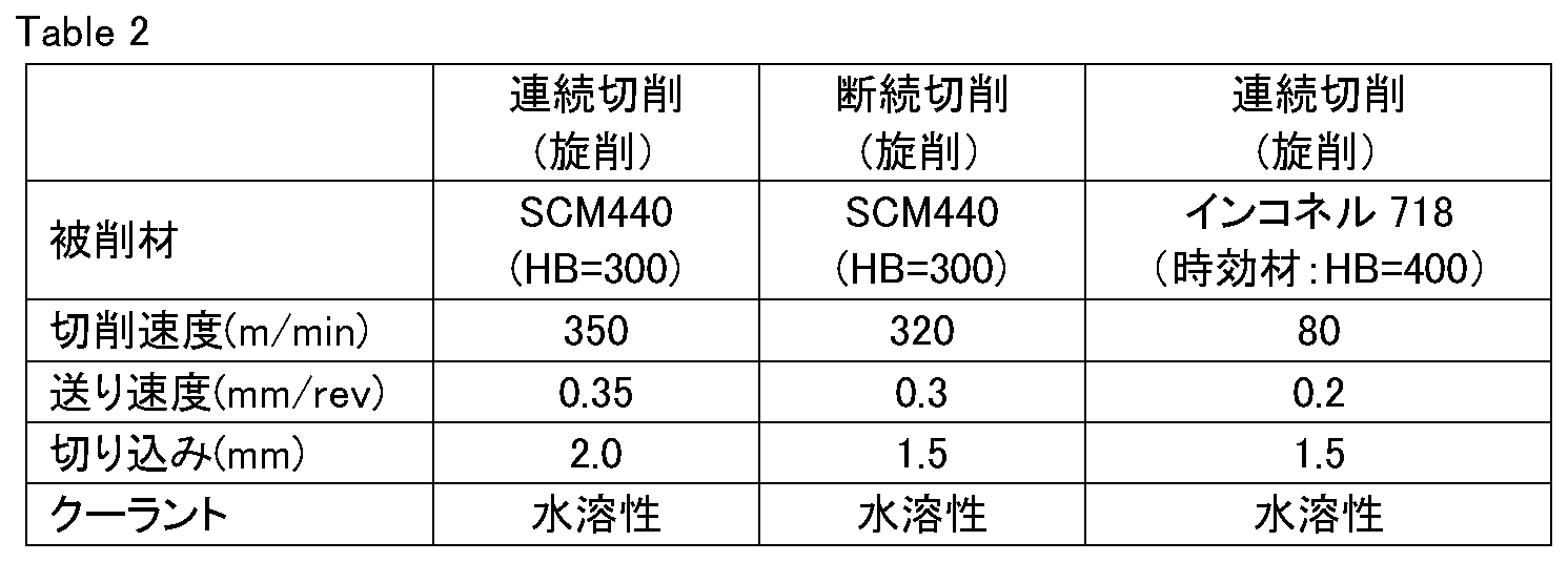
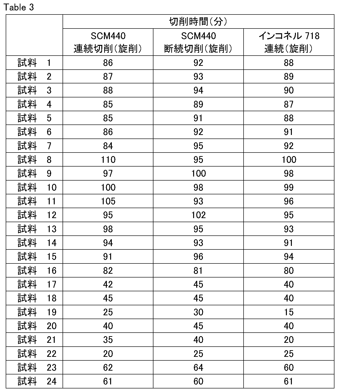
試料1~16、23、24の刃先交換型切削チップは実施例に該当し、試料17~22の刃先交換型切削チップは比較例に該当する。試料1~16、23、24は、試料17~22に比べて、連続旋削試験および断続旋削試験のいずれにおいても刃先の逃げ面摩耗量が大きく低減しており、難削材の高速高能率加工においても、刃先交換型切削チップの寿命が大幅に長くなることが確認された。
(フライス試験)
試料1~24のSEMT13T3AGSN形状の刃先交換型切削チップのそれぞれについて、被削材からなる幅150mmの板の中心線と、それより幅の広いφ160mmのカッターの中心を合わせて、表面フライス削りを、表4に示す乾式のフライス試験の条件で行ない、刃先の逃げ面摩耗量が0.2mmになるまでの切削長を測定した。結果を表5に示す。なお、表5において、切削長の長い方が寿命がより長いことを示している。
試料1~24のSEMT13T3AGSN形状の刃先交換型切削チップのそれぞれについて、被削材からなる幅150mmの板の中心線と、それより幅の広いφ160mmのカッターの中心を合わせて、表面フライス削りを、表4に示す乾式のフライス試験の条件で行ない、刃先の逃げ面摩耗量が0.2mmになるまでの切削長を測定した。結果を表5に示す。なお、表5において、切削長の長い方が寿命がより長いことを示している。
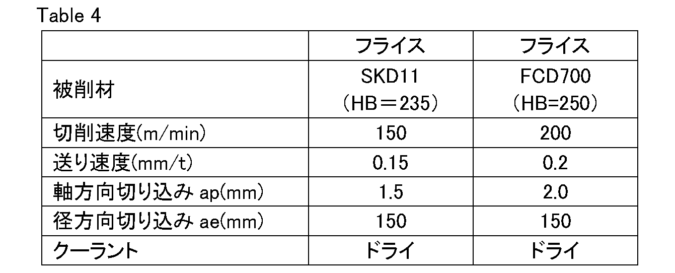

試料1~16、23、24の刃先交換型切削チップは実施例に該当し、試料17~22の刃先交換型切削チップは比較例に該当する。試料1~16、23、24は、試料17~22に比べて、刃先の切削長さが大きく増加しており、高速高能率及びドライ条件下のフライス加工においても刃先交換型切削チップの寿命が大幅に長くなることが確認された。
以上のように本開示の実施の形態および実施例について説明を行なったが、上述の各実施の形態および実施例の構成を適宜組み合わせたり、様々に変形することも当初から予定している。
今回開示された実施の形態および実施例はすべての点で例示であって、制限的なものではないと考えられるべきである。本発明の範囲は上記した実施の形態および実施例ではなく請求の範囲によって示され、請求の範囲と均等の意味、および範囲内でのすべての変更が含まれることが意図される。
1 表面被覆切削工具、2 基材、3 被覆層、12 第1単位層、13 交互層、14 表面層、15 第2単位層、16 下地層、101 チャンバ、103 ガス排出口、104 基材ホルダ、105 ガス、106,107,120 カソード、108,109 アーク電源、110 バイアス電源。
Claims (12)
- 基材と、前記基材を被覆する被覆層とを含む表面被覆切削工具であって、
前記被覆層は、第1単位層と第2単位層とが交互に積層された交互層を含み、
前記第1単位層はアルミニウム及びジルコニウムを含む窒化物からなり、
前記第1単位層において、前記第1単位層を構成する金属原子の総数を1としたときの前記ジルコニウムの原子数の比は0.65以上0.95以下であり、
前記第2単位層はチタン及びアルミニウムを含む窒化物からなり、
前記第2単位層において、前記第2単位層を構成する金属原子の総数を1としたときの前記アルミニウムの原子数の比は0.40よりも大きく0.70以下である、表面被覆切削工具。 - 前記交互層中の隣り合う前記第1単位層と前記第2単位層とにおいて、前記第1単位層の厚みλ1に対する前記第2単位層の厚みλ2の比λ2/λ1は1以上5以下である、請求項1に記載の表面被覆切削工具。
- 前記第1単位層は珪素を含み、
前記第1単位層において、前記第1単位層を構成する金属原子の総数を1としたときの前記珪素の原子数の比は0よりも大きく0.20以下である、請求項1又は請求項2に記載の表面被覆切削工具。 - 前記第2単位層は珪素を含み、
前記第2単位層において、前記第2単位層を構成する金属原子の総数を1としたときの前記珪素の原子数の比は0よりも大きく0.20以下である、請求項1~請求項3のいずれか1項に記載の表面被覆切削工具。 - 前記第1単位層は硼素を含み、
前記第1単位層において、前記第1単位層を構成する金属原子の総数を1としたときの前記硼素の原子数の比は0よりも大きく0.10以下である、請求項1~請求項4のいずれか1項に記載の表面被覆切削工具。 - 前記第2単位層は硼素を含み、
前記第2単位層において、前記第2単位層を構成する金属原子の総数を1としたときの前記硼素の原子数の比は0よりも大きく0.10以下である、請求項1~請求項5のいずれか1項に記載の表面被覆切削工具。 - 前記第1単位層はバナジウムを含み、
前記第1単位層において、前記第1単位層を構成する金属原子の総数を1としたときの前記バナジウムの原子数の比は0よりも大きく0.30以下である、請求項1~請求項6のいずれか1項に記載の表面被覆切削工具。 - 前記第2単位層はバナジウムを含み、
前記第2単位層において、前記第2単位層を構成する金属原子の総数を1としたときの前記バナジウムの原子数の比は0よりも大きく0.30以下である、請求項1~請求項6のいずれか1項に記載の表面被覆切削工具。 - 前記第1単位層及び前記第2単位層は、それぞれ1層の厚みが0.002μm以上0.2μm以下である、請求項1~請求項8のいずれか1項に記載の表面被覆切削工具。
- 前記被覆層は前記基材と前記交互層との間に配置される下地層を含み、
前記下地層は、前記第1単位層又は前記第2単位層と同一の組成を有する、請求項1~請求項9のいずれか1項に記載の表面被覆切削工具。 - 前記被覆層は前記交互層の表面側に配置される表面層を含み、
前記表面層は、チタン及びアルミニウムを含む炭窒化物からなり、
前記表面層において、前記表面層を構成する金属原子の総数を1としたときの前記アルミニウムの原子数の比は0.40よりも大きく0.60以下である、請求項1~請求項10のいずれか1項に記載の表面被覆切削工具。 - 請求項1~請求項11のいずれか1項に記載の表面被覆切削工具の製造方法であって、
前記基材を準備する工程と、
前記基材上に、物理的蒸着法を用いて前記第1単位層と前記第2単位層とを交互に積層することにより前記交互層を形成し、前記表面被覆切削工具を得る工程と、を備える、表面被覆切削工具の製造方法。
Priority Applications (4)
| Application Number | Priority Date | Filing Date | Title |
|---|---|---|---|
| US16/958,183 US11298748B2 (en) | 2018-03-07 | 2018-10-16 | Surface coated cutting tool and method for manufacturing the same |
| JP2020504768A JP7067689B2 (ja) | 2018-03-07 | 2018-10-16 | 表面被覆切削工具及びその製造方法 |
| EP18908401.5A EP3763465B1 (en) | 2018-03-07 | 2018-10-16 | Surface-coated cutting tool and method for producing same |
| CN201880084647.3A CN111587157B (zh) | 2018-03-07 | 2018-10-16 | 表面被覆切削工具及其制造方法 |
Applications Claiming Priority (2)
| Application Number | Priority Date | Filing Date | Title |
|---|---|---|---|
| JP2018-040874 | 2018-03-07 | ||
| JP2018040874 | 2018-03-07 |
Publications (1)
| Publication Number | Publication Date |
|---|---|
| WO2019171648A1 true WO2019171648A1 (ja) | 2019-09-12 |
Family
ID=67847004
Family Applications (1)
| Application Number | Title | Priority Date | Filing Date |
|---|---|---|---|
| PCT/JP2018/038491 Ceased WO2019171648A1 (ja) | 2018-03-07 | 2018-10-16 | 表面被覆切削工具及びその製造方法 |
Country Status (5)
| Country | Link |
|---|---|
| US (1) | US11298748B2 (ja) |
| EP (1) | EP3763465B1 (ja) |
| JP (1) | JP7067689B2 (ja) |
| CN (1) | CN111587157B (ja) |
| WO (1) | WO2019171648A1 (ja) |
Cited By (2)
| Publication number | Priority date | Publication date | Assignee | Title |
|---|---|---|---|---|
| JPWO2020070967A1 (ja) * | 2018-10-03 | 2021-09-02 | 住友電工ハードメタル株式会社 | 表面被覆切削工具及びその製造方法 |
| JP2022142880A (ja) * | 2021-03-17 | 2022-10-03 | 三菱マテリアル株式会社 | 表面被覆切削工具 |
Families Citing this family (4)
| Publication number | Priority date | Publication date | Assignee | Title |
|---|---|---|---|---|
| WO2020075698A1 (ja) * | 2018-10-11 | 2020-04-16 | 株式会社不二越 | 硬質皮膜被覆ドリル |
| EP4386110A1 (en) * | 2022-12-16 | 2024-06-19 | AB Sandvik Coromant | A coated cutting tool |
| CN116288184B (zh) * | 2023-02-24 | 2025-08-15 | 厦门钨业股份有限公司 | 纳米多层复合涂层及其制备方法和切削工具 |
| CN116180023B (zh) * | 2023-02-24 | 2025-06-13 | 厦门钨业股份有限公司 | 纳米多层结构涂层及其制备方法和应用 |
Citations (12)
| Publication number | Priority date | Publication date | Assignee | Title |
|---|---|---|---|---|
| JP2003034858A (ja) * | 2001-07-23 | 2003-02-07 | Kobe Steel Ltd | 切削工具用硬質皮膜およびその製造方法並びに硬質皮膜形成用ターゲット |
| JP2003034859A (ja) | 2001-07-23 | 2003-02-07 | Kobe Steel Ltd | 切削工具用硬質皮膜およびその製造方法並びに硬質皮膜形成用ターゲット |
| WO2006070730A1 (ja) | 2004-12-28 | 2006-07-06 | Sumitomo Electric Hardmetal Corp. | 表面被覆切削工具および表面被覆切削工具の製造方法 |
| JP2006281409A (ja) * | 2005-04-04 | 2006-10-19 | Mitsubishi Materials Corp | 高硬度鋼の高速切削加工で硬質被覆層がすぐれた耐摩耗性を発揮する表面被覆超硬合金製切削工具 |
| JP2007007742A (ja) * | 2005-06-28 | 2007-01-18 | Mitsubishi Materials Corp | 高硬度鋼の高速切削加工で硬質被覆層がすぐれた耐摩耗性を発揮する表面被覆切削工具 |
| JP2007191765A (ja) * | 2006-01-20 | 2007-08-02 | Kobe Steel Ltd | 硬質皮膜 |
| JP2010180479A (ja) * | 2005-02-08 | 2010-08-19 | Kobe Steel Ltd | 硬質皮膜および硬質皮膜の製造方法 |
| JP2010247262A (ja) * | 2009-04-15 | 2010-11-04 | Tungaloy Corp | 被覆cBN焼結体 |
| JP2011212786A (ja) * | 2010-03-31 | 2011-10-27 | Sumitomo Electric Hardmetal Corp | 表面被覆切削工具 |
| JP2015512791A (ja) * | 2012-02-14 | 2015-04-30 | サンドビック インテレクチュアル プロパティー アクティエボラーグ | 被覆された切削工具及びその製造方法 |
| JP2016211052A (ja) * | 2015-05-12 | 2016-12-15 | 株式会社神戸製鋼所 | 硬質皮膜および硬質皮膜被覆部材 |
| JP2018040874A (ja) | 2016-09-06 | 2018-03-15 | キヤノン株式会社 | 画像形成装置、画像形成装置の制御方法、及びプログラム |
Family Cites Families (15)
| Publication number | Priority date | Publication date | Assignee | Title |
|---|---|---|---|---|
| DE10233222B4 (de) | 2001-07-23 | 2007-03-01 | Kabushiki Kaisha Kobe Seiko Sho (Kobe Steel, Ltd.), Kobe | Harte verschleissfeste Schicht, Verfahren zum Bilden derselben und Verwendung |
| SE526336C2 (sv) * | 2002-07-01 | 2005-08-23 | Seco Tools Ab | Skär med slitstark refraktär beläggning av MAX-fas |
| JP4367032B2 (ja) * | 2003-07-09 | 2009-11-18 | 三菱マテリアル株式会社 | 高速切削加工で硬質被覆層がすぐれた耐摩耗性を発揮する表面被覆超硬合金製切削工具 |
| JP3934136B2 (ja) * | 2004-11-11 | 2007-06-20 | 日立ツール株式会社 | 硬質皮膜被覆部材及びその被覆方法 |
| WO2006070509A1 (ja) * | 2004-12-28 | 2006-07-06 | Sumitomo Electric Hardmetal Corp. | 表面被覆切削工具および表面被覆切削工具の製造方法 |
| JP4939032B2 (ja) | 2005-02-08 | 2012-05-23 | 株式会社神戸製鋼所 | 硬質皮膜、および硬質皮膜の製造方法 |
| DE102006046915C5 (de) * | 2006-10-04 | 2015-09-03 | Federal-Mogul Burscheid Gmbh | Kolbenring für Verbrennungskraftmaschinen |
| US20090060669A1 (en) * | 2007-09-05 | 2009-03-05 | Sandvik Intellectual Property Ab | Coated drill and a method of making the same |
| US8715838B2 (en) * | 2010-11-10 | 2014-05-06 | Sumitomo Electric Hardmetal Corp. | Surface-coated cutting tool |
| EP2636764B1 (en) * | 2012-03-07 | 2014-07-09 | Seco Tools Ab | Nanolaminated coated cutting tool |
| DE102012017731A1 (de) * | 2012-09-08 | 2014-03-13 | Oerlikon Trading Ag, Trübbach | Ti-Al-Ta-basierte Beschichtung mit einer verbesserten Temperaturbeständigkeit |
| JP5663815B2 (ja) * | 2013-07-03 | 2015-02-04 | 住友電工ハードメタル株式会社 | 表面被覆窒化硼素焼結体工具 |
| US10583493B2 (en) | 2015-04-27 | 2020-03-10 | Tungaloy Corporation | Coated cutting tool |
| KR101753104B1 (ko) | 2015-09-18 | 2017-07-05 | 한국야금 주식회사 | 절삭공구용 경질피막 |
| US10737332B2 (en) * | 2016-04-07 | 2020-08-11 | Tungaloy Corporation | Coated cutting tool |
-
2018
- 2018-10-16 JP JP2020504768A patent/JP7067689B2/ja active Active
- 2018-10-16 CN CN201880084647.3A patent/CN111587157B/zh active Active
- 2018-10-16 US US16/958,183 patent/US11298748B2/en active Active
- 2018-10-16 WO PCT/JP2018/038491 patent/WO2019171648A1/ja not_active Ceased
- 2018-10-16 EP EP18908401.5A patent/EP3763465B1/en active Active
Patent Citations (12)
| Publication number | Priority date | Publication date | Assignee | Title |
|---|---|---|---|---|
| JP2003034858A (ja) * | 2001-07-23 | 2003-02-07 | Kobe Steel Ltd | 切削工具用硬質皮膜およびその製造方法並びに硬質皮膜形成用ターゲット |
| JP2003034859A (ja) | 2001-07-23 | 2003-02-07 | Kobe Steel Ltd | 切削工具用硬質皮膜およびその製造方法並びに硬質皮膜形成用ターゲット |
| WO2006070730A1 (ja) | 2004-12-28 | 2006-07-06 | Sumitomo Electric Hardmetal Corp. | 表面被覆切削工具および表面被覆切削工具の製造方法 |
| JP2010180479A (ja) * | 2005-02-08 | 2010-08-19 | Kobe Steel Ltd | 硬質皮膜および硬質皮膜の製造方法 |
| JP2006281409A (ja) * | 2005-04-04 | 2006-10-19 | Mitsubishi Materials Corp | 高硬度鋼の高速切削加工で硬質被覆層がすぐれた耐摩耗性を発揮する表面被覆超硬合金製切削工具 |
| JP2007007742A (ja) * | 2005-06-28 | 2007-01-18 | Mitsubishi Materials Corp | 高硬度鋼の高速切削加工で硬質被覆層がすぐれた耐摩耗性を発揮する表面被覆切削工具 |
| JP2007191765A (ja) * | 2006-01-20 | 2007-08-02 | Kobe Steel Ltd | 硬質皮膜 |
| JP2010247262A (ja) * | 2009-04-15 | 2010-11-04 | Tungaloy Corp | 被覆cBN焼結体 |
| JP2011212786A (ja) * | 2010-03-31 | 2011-10-27 | Sumitomo Electric Hardmetal Corp | 表面被覆切削工具 |
| JP2015512791A (ja) * | 2012-02-14 | 2015-04-30 | サンドビック インテレクチュアル プロパティー アクティエボラーグ | 被覆された切削工具及びその製造方法 |
| JP2016211052A (ja) * | 2015-05-12 | 2016-12-15 | 株式会社神戸製鋼所 | 硬質皮膜および硬質皮膜被覆部材 |
| JP2018040874A (ja) | 2016-09-06 | 2018-03-15 | キヤノン株式会社 | 画像形成装置、画像形成装置の制御方法、及びプログラム |
Non-Patent Citations (3)
| Title |
|---|
| "The Society of Materials Science", 1981, YOKENDO CO., LTD., article "X-Ray Stress Measurement", pages: 54 - 66 |
| MAKINO: "Journal of the High Temperature Society", vol. 33, March 2007, HIGH TEMPERATURE SOCIETY, article "Structural Control and Properties of Pseudobinary Nitride Hard Coatings", pages: 50 - 59 |
| See also references of EP3763465A4 |
Cited By (4)
| Publication number | Priority date | Publication date | Assignee | Title |
|---|---|---|---|---|
| JPWO2020070967A1 (ja) * | 2018-10-03 | 2021-09-02 | 住友電工ハードメタル株式会社 | 表面被覆切削工具及びその製造方法 |
| JP7055961B2 (ja) | 2018-10-03 | 2022-04-19 | 住友電工ハードメタル株式会社 | 表面被覆切削工具及びその製造方法 |
| JP2022142880A (ja) * | 2021-03-17 | 2022-10-03 | 三菱マテリアル株式会社 | 表面被覆切削工具 |
| JP7570599B2 (ja) | 2021-03-17 | 2024-10-22 | 三菱マテリアル株式会社 | 表面被覆切削工具 |
Also Published As
| Publication number | Publication date |
|---|---|
| JPWO2019171648A1 (ja) | 2020-12-17 |
| JP7067689B2 (ja) | 2022-05-16 |
| EP3763465A4 (en) | 2021-08-04 |
| CN111587157B (zh) | 2023-06-20 |
| US11298748B2 (en) | 2022-04-12 |
| CN111587157A (zh) | 2020-08-25 |
| EP3763465A1 (en) | 2021-01-13 |
| US20210069794A1 (en) | 2021-03-11 |
| EP3763465B1 (en) | 2024-11-06 |
Similar Documents
| Publication | Publication Date | Title |
|---|---|---|
| JP7067689B2 (ja) | 表面被覆切削工具及びその製造方法 | |
| WO2017169498A1 (ja) | 表面被覆切削工具、およびその製造方法 | |
| JP6984108B2 (ja) | 表面被覆切削工具及びその製造方法 | |
| JP7055961B2 (ja) | 表面被覆切削工具及びその製造方法 | |
| WO2024236770A1 (ja) | 切削工具 | |
| JP7652342B1 (ja) | 切削工具 | |
| JP7652343B1 (ja) | 切削工具 | |
| JP7409555B1 (ja) | 切削工具 | |
| US12173411B2 (en) | Cutting tool | |
| JP7409561B1 (ja) | 切削工具 | |
| JP7420318B1 (ja) | 切削工具 | |
| JP7708333B1 (ja) | 切削工具 | |
| JP7537627B1 (ja) | 切削工具 | |
| US12138692B2 (en) | Cutting tool | |
| US20260117363A1 (en) | Cutting tool | |
| US20260115801A1 (en) | Cutting tool | |
| WO2024236769A1 (ja) | 切削工具 |
Legal Events
| Date | Code | Title | Description |
|---|---|---|---|
| 121 | Ep: the epo has been informed by wipo that ep was designated in this application |
Ref document number: 18908401 Country of ref document: EP Kind code of ref document: A1 |
|
| ENP | Entry into the national phase |
Ref document number: 2020504768 Country of ref document: JP Kind code of ref document: A |
|
| NENP | Non-entry into the national phase |
Ref country code: DE |
|
| ENP | Entry into the national phase |
Ref document number: 2018908401 Country of ref document: EP Effective date: 20201007 |