WO2019171694A1 - 大動脈治療装置 - Google Patents
大動脈治療装置 Download PDFInfo
- Publication number
- WO2019171694A1 WO2019171694A1 PCT/JP2018/045473 JP2018045473W WO2019171694A1 WO 2019171694 A1 WO2019171694 A1 WO 2019171694A1 JP 2018045473 W JP2018045473 W JP 2018045473W WO 2019171694 A1 WO2019171694 A1 WO 2019171694A1
- Authority
- WO
- WIPO (PCT)
- Prior art keywords
- blood vessel
- artificial blood
- branched artificial
- aorta
- stent graft
- Prior art date
- Legal status (The legal status is an assumption and is not a legal conclusion. Google has not performed a legal analysis and makes no representation as to the accuracy of the status listed.)
- Ceased
Links
Images



Classifications
-
- A—HUMAN NECESSITIES
- A61—MEDICAL OR VETERINARY SCIENCE; HYGIENE
- A61F—FILTERS IMPLANTABLE INTO BLOOD VESSELS; PROSTHESES; DEVICES PROVIDING PATENCY TO, OR PREVENTING COLLAPSING OF, TUBULAR STRUCTURES OF THE BODY, e.g. STENTS; ORTHOPAEDIC, NURSING OR CONTRACEPTIVE DEVICES; FOMENTATION; TREATMENT OR PROTECTION OF EYES OR EARS; BANDAGES, DRESSINGS OR ABSORBENT PADS; FIRST-AID KITS
- A61F2/00—Filters implantable into blood vessels; Prostheses, i.e. artificial substitutes or replacements for parts of the body; Appliances for connecting them with the body; Devices providing patency to, or preventing collapsing of, tubular structures of the body, e.g. stents
- A61F2/82—Devices providing patency to, or preventing collapsing of, tubular structures of the body, e.g. stents
- A61F2/852—Two or more distinct overlapping stents
-
- A—HUMAN NECESSITIES
- A61—MEDICAL OR VETERINARY SCIENCE; HYGIENE
- A61F—FILTERS IMPLANTABLE INTO BLOOD VESSELS; PROSTHESES; DEVICES PROVIDING PATENCY TO, OR PREVENTING COLLAPSING OF, TUBULAR STRUCTURES OF THE BODY, e.g. STENTS; ORTHOPAEDIC, NURSING OR CONTRACEPTIVE DEVICES; FOMENTATION; TREATMENT OR PROTECTION OF EYES OR EARS; BANDAGES, DRESSINGS OR ABSORBENT PADS; FIRST-AID KITS
- A61F2/00—Filters implantable into blood vessels; Prostheses, i.e. artificial substitutes or replacements for parts of the body; Appliances for connecting them with the body; Devices providing patency to, or preventing collapsing of, tubular structures of the body, e.g. stents
- A61F2/02—Prostheses implantable into the body
- A61F2/04—Hollow or tubular parts of organs, e.g. bladders, tracheae, bronchi or bile ducts
- A61F2/06—Blood vessels
- A61F2/064—Blood vessels with special features to facilitate anastomotic coupling
-
- A—HUMAN NECESSITIES
- A61—MEDICAL OR VETERINARY SCIENCE; HYGIENE
- A61F—FILTERS IMPLANTABLE INTO BLOOD VESSELS; PROSTHESES; DEVICES PROVIDING PATENCY TO, OR PREVENTING COLLAPSING OF, TUBULAR STRUCTURES OF THE BODY, e.g. STENTS; ORTHOPAEDIC, NURSING OR CONTRACEPTIVE DEVICES; FOMENTATION; TREATMENT OR PROTECTION OF EYES OR EARS; BANDAGES, DRESSINGS OR ABSORBENT PADS; FIRST-AID KITS
- A61F2/00—Filters implantable into blood vessels; Prostheses, i.e. artificial substitutes or replacements for parts of the body; Appliances for connecting them with the body; Devices providing patency to, or preventing collapsing of, tubular structures of the body, e.g. stents
- A61F2/02—Prostheses implantable into the body
- A61F2/04—Hollow or tubular parts of organs, e.g. bladders, tracheae, bronchi or bile ducts
- A61F2/06—Blood vessels
- A61F2/07—Stent-grafts
-
- A—HUMAN NECESSITIES
- A61—MEDICAL OR VETERINARY SCIENCE; HYGIENE
- A61F—FILTERS IMPLANTABLE INTO BLOOD VESSELS; PROSTHESES; DEVICES PROVIDING PATENCY TO, OR PREVENTING COLLAPSING OF, TUBULAR STRUCTURES OF THE BODY, e.g. STENTS; ORTHOPAEDIC, NURSING OR CONTRACEPTIVE DEVICES; FOMENTATION; TREATMENT OR PROTECTION OF EYES OR EARS; BANDAGES, DRESSINGS OR ABSORBENT PADS; FIRST-AID KITS
- A61F2/00—Filters implantable into blood vessels; Prostheses, i.e. artificial substitutes or replacements for parts of the body; Appliances for connecting them with the body; Devices providing patency to, or preventing collapsing of, tubular structures of the body, e.g. stents
- A61F2/02—Prostheses implantable into the body
- A61F2/04—Hollow or tubular parts of organs, e.g. bladders, tracheae, bronchi or bile ducts
- A61F2/06—Blood vessels
- A61F2002/061—Blood vessels provided with means for allowing access to secondary lumens
-
- A—HUMAN NECESSITIES
- A61—MEDICAL OR VETERINARY SCIENCE; HYGIENE
- A61F—FILTERS IMPLANTABLE INTO BLOOD VESSELS; PROSTHESES; DEVICES PROVIDING PATENCY TO, OR PREVENTING COLLAPSING OF, TUBULAR STRUCTURES OF THE BODY, e.g. STENTS; ORTHOPAEDIC, NURSING OR CONTRACEPTIVE DEVICES; FOMENTATION; TREATMENT OR PROTECTION OF EYES OR EARS; BANDAGES, DRESSINGS OR ABSORBENT PADS; FIRST-AID KITS
- A61F2/00—Filters implantable into blood vessels; Prostheses, i.e. artificial substitutes or replacements for parts of the body; Appliances for connecting them with the body; Devices providing patency to, or preventing collapsing of, tubular structures of the body, e.g. stents
- A61F2/02—Prostheses implantable into the body
- A61F2/04—Hollow or tubular parts of organs, e.g. bladders, tracheae, bronchi or bile ducts
- A61F2/06—Blood vessels
- A61F2002/065—Y-shaped blood vessels
- A61F2002/067—Y-shaped blood vessels modular
-
- A—HUMAN NECESSITIES
- A61—MEDICAL OR VETERINARY SCIENCE; HYGIENE
- A61F—FILTERS IMPLANTABLE INTO BLOOD VESSELS; PROSTHESES; DEVICES PROVIDING PATENCY TO, OR PREVENTING COLLAPSING OF, TUBULAR STRUCTURES OF THE BODY, e.g. STENTS; ORTHOPAEDIC, NURSING OR CONTRACEPTIVE DEVICES; FOMENTATION; TREATMENT OR PROTECTION OF EYES OR EARS; BANDAGES, DRESSINGS OR ABSORBENT PADS; FIRST-AID KITS
- A61F2/00—Filters implantable into blood vessels; Prostheses, i.e. artificial substitutes or replacements for parts of the body; Appliances for connecting them with the body; Devices providing patency to, or preventing collapsing of, tubular structures of the body, e.g. stents
- A61F2/02—Prostheses implantable into the body
- A61F2/04—Hollow or tubular parts of organs, e.g. bladders, tracheae, bronchi or bile ducts
- A61F2/06—Blood vessels
- A61F2/07—Stent-grafts
- A61F2002/075—Stent-grafts the stent being loosely attached to the graft material, e.g. by stitching
-
- A—HUMAN NECESSITIES
- A61—MEDICAL OR VETERINARY SCIENCE; HYGIENE
- A61F—FILTERS IMPLANTABLE INTO BLOOD VESSELS; PROSTHESES; DEVICES PROVIDING PATENCY TO, OR PREVENTING COLLAPSING OF, TUBULAR STRUCTURES OF THE BODY, e.g. STENTS; ORTHOPAEDIC, NURSING OR CONTRACEPTIVE DEVICES; FOMENTATION; TREATMENT OR PROTECTION OF EYES OR EARS; BANDAGES, DRESSINGS OR ABSORBENT PADS; FIRST-AID KITS
- A61F2/00—Filters implantable into blood vessels; Prostheses, i.e. artificial substitutes or replacements for parts of the body; Appliances for connecting them with the body; Devices providing patency to, or preventing collapsing of, tubular structures of the body, e.g. stents
- A61F2/02—Prostheses implantable into the body
- A61F2/04—Hollow or tubular parts of organs, e.g. bladders, tracheae, bronchi or bile ducts
- A61F2/06—Blood vessels
- A61F2/07—Stent-grafts
- A61F2002/077—Stent-grafts having means to fill the space between stent-graft and aneurysm wall, e.g. a sleeve
-
- A—HUMAN NECESSITIES
- A61—MEDICAL OR VETERINARY SCIENCE; HYGIENE
- A61F—FILTERS IMPLANTABLE INTO BLOOD VESSELS; PROSTHESES; DEVICES PROVIDING PATENCY TO, OR PREVENTING COLLAPSING OF, TUBULAR STRUCTURES OF THE BODY, e.g. STENTS; ORTHOPAEDIC, NURSING OR CONTRACEPTIVE DEVICES; FOMENTATION; TREATMENT OR PROTECTION OF EYES OR EARS; BANDAGES, DRESSINGS OR ABSORBENT PADS; FIRST-AID KITS
- A61F2220/00—Fixations or connections for prostheses classified in groups A61F2/00 - A61F2/26 or A61F2/82 or A61F9/00 or A61F11/00 or subgroups thereof
- A61F2220/0008—Fixation appliances for connecting prostheses to the body
-
- A—HUMAN NECESSITIES
- A61—MEDICAL OR VETERINARY SCIENCE; HYGIENE
- A61F—FILTERS IMPLANTABLE INTO BLOOD VESSELS; PROSTHESES; DEVICES PROVIDING PATENCY TO, OR PREVENTING COLLAPSING OF, TUBULAR STRUCTURES OF THE BODY, e.g. STENTS; ORTHOPAEDIC, NURSING OR CONTRACEPTIVE DEVICES; FOMENTATION; TREATMENT OR PROTECTION OF EYES OR EARS; BANDAGES, DRESSINGS OR ABSORBENT PADS; FIRST-AID KITS
- A61F2220/00—Fixations or connections for prostheses classified in groups A61F2/00 - A61F2/26 or A61F2/82 or A61F9/00 or A61F11/00 or subgroups thereof
- A61F2220/0025—Connections or couplings between prosthetic parts, e.g. between modular parts; Connecting elements
- A61F2220/0075—Connections or couplings between prosthetic parts, e.g. between modular parts; Connecting elements sutured, ligatured or stitched, retained or tied with a rope, string, thread, wire or cable
-
- A—HUMAN NECESSITIES
- A61—MEDICAL OR VETERINARY SCIENCE; HYGIENE
- A61F—FILTERS IMPLANTABLE INTO BLOOD VESSELS; PROSTHESES; DEVICES PROVIDING PATENCY TO, OR PREVENTING COLLAPSING OF, TUBULAR STRUCTURES OF THE BODY, e.g. STENTS; ORTHOPAEDIC, NURSING OR CONTRACEPTIVE DEVICES; FOMENTATION; TREATMENT OR PROTECTION OF EYES OR EARS; BANDAGES, DRESSINGS OR ABSORBENT PADS; FIRST-AID KITS
- A61F2250/00—Special features of prostheses classified in groups A61F2/00 - A61F2/26 or A61F2/82 or A61F9/00 or A61F11/00 or subgroups thereof
- A61F2250/0014—Special features of prostheses classified in groups A61F2/00 - A61F2/26 or A61F2/82 or A61F9/00 or A61F11/00 or subgroups thereof having different values of a given property or geometrical feature, e.g. mechanical property or material property, at different locations within the same prosthesis
- A61F2250/0039—Special features of prostheses classified in groups A61F2/00 - A61F2/26 or A61F2/82 or A61F9/00 or A61F11/00 or subgroups thereof having different values of a given property or geometrical feature, e.g. mechanical property or material property, at different locations within the same prosthesis differing in diameter
-
- A—HUMAN NECESSITIES
- A61—MEDICAL OR VETERINARY SCIENCE; HYGIENE
- A61F—FILTERS IMPLANTABLE INTO BLOOD VESSELS; PROSTHESES; DEVICES PROVIDING PATENCY TO, OR PREVENTING COLLAPSING OF, TUBULAR STRUCTURES OF THE BODY, e.g. STENTS; ORTHOPAEDIC, NURSING OR CONTRACEPTIVE DEVICES; FOMENTATION; TREATMENT OR PROTECTION OF EYES OR EARS; BANDAGES, DRESSINGS OR ABSORBENT PADS; FIRST-AID KITS
- A61F2250/00—Special features of prostheses classified in groups A61F2/00 - A61F2/26 or A61F2/82 or A61F9/00 or A61F11/00 or subgroups thereof
- A61F2250/0058—Additional features; Implant or prostheses properties not otherwise provided for
- A61F2250/006—Additional features; Implant or prostheses properties not otherwise provided for modular
Definitions
- the present invention relates to a treatment apparatus for treating a disease in the thoracic aorta.
- a branched artificial blood vessel in which four side tubes are derived is known as an artificial blood vessel used for artificial blood vessel replacement for replacing an aortic arch (Patent Document 1 below).
- various stent grafts used for stent graft insertion are known.
- a stent graft having a structure capable of improving the convenience of treatment by the OSG (Open Stent Graft) method is disclosed in the present application. It has been proposed by a person (Patent Document 2 below).
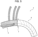
- FIG. 5 is an explanatory view showing such a treatment apparatus.
- the treatment apparatus 1 includes a branch artificial blood vessel part 3, a stent graft part 5 sewn on the distal side, and a branch artificial blood vessel part. 3 and a flange-like collar 7 attached to the stitched portion of the stent graft portion 5.
- the treatment device 1 is mounted as follows using a delivery system (not shown). First, the stent graft part 5 in a reduced diameter state is inserted into the distal aorta (descending part of the aorta), which is a biological blood vessel, from the dissection part after the aortic arch resection, and the distal aorta is inserted by the flange-like collar 7. The treatment device 1 is arranged so as to close the opening of the proximal end portion (the separation portion).
- the diameter of the stent graft portion 5 is expanded to bring it into close contact with the inner wall of the distal aorta, and if necessary, the size of the collar 7 is adjusted by cutting off a part thereof.
- the distal aorta and the branched artificial blood vessel 3 are anastomosed by suturing the proximal end of the distal aorta.
- the proximal artificial end of the branched artificial blood vessel 3 and the proximal aorta (ascending portion of the aorta), which is a biological blood vessel, are stitched together to connect the branched artificial blood vessel 3 and the proximal aorta. Anastomoses.
- the proximal end portion of the distal aorta whose end face shape varies depending on the patient, and the flange-like collar are aligned, and both are sewn together while adjusting the shape and size of each other.
- the procedure is extremely difficult, and there is a problem that tension is likely to remain after suturing.
- the inner diameter of the distal aorta varies depending on the patient.
- the stent graft should be sufficiently adhered to the inner wall of the distal aorta. May not be possible.
- An object of the present invention is to replace the aortic arch with a branched artificial blood vessel, and to place a stent graft in the distal aorta, and anastomosis between the branched artificial blood vessel and the distal aorta It is an object of the present invention to provide an aortic treatment device that can be easily performed as compared with conventional devices.
- Another object of the present invention is to treat an aorta having a stent graft portion that can sufficiently adhere to an inner wall of a distal aorta, which has insufficient adhesion in a stent graft portion constituting a conventional treatment apparatus. To provide an apparatus.
- the aortic treatment device includes a branched artificial blood vessel portion in which at least one side tube is derived from a main tube; A stent graft connected to the distal side of the branched artificial blood vessel, Formed so as to extend distally from the distal end of the branched artificial blood vessel portion, and is rotatable so as to be in a state of extending proximally from the distal end of the branched artificial blood vessel portion; A cuff portion having a cylindrical shape or a skirt shape is provided.
- the cuff portion is rotated, and the diameter of the cuff portion is reduced until the position of the open end of the cuff portion approximately matches the position of the proximal end of the distal aorta.
- the proximal end of the distal aorta and the cuff part in the inverted state are By suturing, the distal aorta and the branched artificial blood vessel can be anastomosed.
- both of them can be arranged in a substantially concentric cylindrical shape, so that a conventional treatment device having a flange-like collar and In comparison, the technique of stitching the two is much easier, and no tension remains after the stitching.
- the branched artificial blood vessel portion is formed by deriving four side tubes from the main tube.
- the cuff part is continuously formed at the distal end of the branched artificial blood vessel part with the same material as the branched artificial blood vessel part (that is, the The branched artificial blood vessel portion and the cuff portion are formed of a common tubular knitted fabric), and the stent graft portion is sutured to the distal end of the branched artificial blood vessel portion, thereby It is preferably connected to the artificial blood vessel part.
- the integrity of the branched artificial blood vessel portion and the cuff portion can be further improved.
- the ratio of the inner diameter of the stent graft portion to the inner diameter of the main tube of the branched artificial blood vessel portion is preferably 1.01 to 1.5.
- the stent graft portion since the ratio of the inner diameter is 1.01 or more, in the conventional treatment device, the stent graft portion has insufficient adhesion to the inner wall of the distal aorta. However, sufficient adhesion of the stent graft portion can be ensured.
- the cuff portion has a skirt shape having a length of 5 to 30 mm and a ratio of the inner diameter of the open end to the inner diameter of the base end of 1.05 to 1.3. preferable.
- the ratio of the inner diameter is a skirt having a ratio of 1.3 or less, the suture with the proximal end of the distal aorta can be performed more easily. Further, when the ratio of the inner diameters is 1.05 or more, the suture can be easily performed even if the shape (size) of the proximal end of the distal aorta is large. In addition, the cuff portion can be easily rotated.
- the branch artificial blood vessel part and the cuff part are subjected to a coating process for preventing blood leakage, and the stent graft part is subjected to such a coating process.
- the stent graft part is subjected to such a coating process.
- the stent graft part is subjected to such a coating process.
- the treatment device having such a configuration, it is possible to prevent blood leakage in the branched artificial blood vessel portion and the cuff portion subjected to the covering process, and the stent graft portion not subjected to the covering process is flexible. Therefore, it is easy to reduce the diameter, has good fitting properties with blood vessels, and is excellent in affinity with living tissue. Further, even after being stored for a long time in a reduced diameter state, the diameter expanding operation is not adversely affected and the storage stability is excellent.
- the aortic arch can be replaced by the branched artificial blood vessel, and the stent graft can be placed in the distal aorta, and the branched artificial blood vessel, the distal aorta, This anastomosis can be easily performed as compared with a conventional treatment apparatus.
- the stent graft portion constituting the conventional treatment device is sufficient.
- the stent graft portion constituting the treatment apparatus of the present invention can be sufficiently adhered even to the inner wall of the distal aorta that cannot be adhered to the distal end.
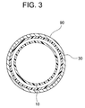
- FIG. 3 is a cross-sectional view taken along the line III-III in FIG.
- FIG. 3 is a cross-sectional view taken along the line III-III in FIG.
- FIG. 3 is a cross-sectional view taken along the line III-III in FIG.
- FIG. 3 is a cross-sectional view taken along the line III-III in FIG.
- FIG. 3 is a cross-sectional view taken along the line III-III in FIG.
- FIG. 3 is a cross-sectional view taken along the line III-III in FIG.
- FIG. 3 is a cross-sectional view taken along the line III-III in FIG.
- FIG. 3 is a cross-sectional view taken along the line III-III in FIG.
- FIG. 3 is a cross-sectional view taken along the line III-III in FIG.
- FIG. 3 is a cross-sectional view taken along the line III-III in FIG.
- FIG. 3 is a cross-sectional view taken along the line III-III in FIG.
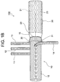
- the aortic treatment device 100 of this embodiment shown in FIG. 1 includes a branched artificial blood vessel portion 10 in which four side tubes 11 to 14 are derived from a main tube 15, and the branched branch A stent graft portion 20 connected to the distal side of the branched artificial blood vessel portion 10 by being sutured to the distal end 16 of the artificial blood vessel portion 10 and a distal end 16 of the branched artificial blood vessel portion 10.
- a skirt-like cuff portion 30 that is formed to extend to the distal side and that extends to the proximal side from the distal end 16 of the branched artificial blood vessel portion 10 by turning. I have.
- the branched artificial blood vessel 10 constituting the treatment device 100 of the present embodiment includes a main tube 15 and four side tubes 11 to 14 derived from the main tube 15.
- the main pipe 15 and the side pipes 11 to 14 are made of a tubular knitted fabric.
- the main pipe 15 and the side pipes 11 to 14 are formed with horizontal folds, are strong against expansion and contraction, have excellent kink resistance, and are easily adapted to the blood vessel shape of the human body.
- the length (free length) of the main pipe 15 is preferably 100 to 400 mm, and is 210 mm as a suitable example.
- the inner diameter of the main pipe 15 is preferably 16 to 36 mm, and is 26 mm if a suitable example is shown.
- the three side pipes 11 to 13 form a group, and the side pipes 14 are arranged out of this group.
- the length of the side tubes 11 to 14 is preferably 50 to 300 mm, and is 210 mm as a suitable example.
- the inner diameter of the side tube 11 is preferably 5 to 14 mm, and is 11 mm as a suitable example.
- the inner diameters of the side pipes 12 to 13 are preferably 5 to 12 mm, and a suitable example is 9 mm.
- the inner diameter of the side tube 14 is preferably 8 to 12 mm, and a suitable example is 9 mm.
- tubular knitted fabric constituting the branched artificial blood vessel portion 10 (main tube 15 and side tubes 11 to 14)
- a tubular product made of a woven fabric or a knitted fabric of thermoplastic resin fibers can be used as the tubular knitted fabric constituting the branched artificial blood vessel portion 10 (main tube 15 and side tubes 11 to 14).
- a woven fabric can be suitably used.
- the wall thickness of the tubular knitted fabric is preferably 1 mm or less, more preferably 0.3 to 0.7 mm.
- thermoplastic resin forming the thermoplastic resin fiber examples include polyolefins such as polyethylene, polypropylene, and ethylene- ⁇ -olefin copolymers, polyamide, polyurethane, polyethylene terephthalate, polybutylene terephthalate, polycyclohexane terephthalate, polyethylene-2,6- Examples thereof include polyesters such as naphthalate and fluororesins such as PTFE and ETFE. Of these, polyesters such as polyethylene terephthalate, fluororesins such as PTFE and ETFE, which are chemically stable and have good durability and little tissue reaction, are preferred, and a weight average molecular weight of 10,000 to 200,000 is particularly preferred. It is a polyester having a weight average molecular weight of 15,000 to 100,000.
- the artificial blood vessel portion 10 with a cocoon branch is coated with collagen, gelatin, or the like, so that blood leakage from the artificial blood vessel portion 10 with a branch can be prevented.
- the stent graft part 20 which comprises the treatment apparatus 100 of this embodiment is provided with the self-expanding stent 21 which can be hold
- FIG. 1 The stent graft part 20 which comprises the treatment apparatus 100 of this embodiment is provided with the self-expanding stent 21 which can be hold
- FIG. 1 FIG. 1 (FIGS. 1A and 1B), the stent graft portion 20 is shown in an expanded state, but is mounted on a delivery shaft (not shown) in a reduced diameter state until the diameter is expanded in a living blood vessel. .
- the length of the stent graft portion 20 is preferably 60 to 210 mm, and 110 mm is shown as a suitable example.
- the diameter of the expanded stent graft portion 20 is larger than the diameter of the main tube 15 of the branched artificial blood vessel portion 10.
- the inner diameter of the stent graft portion 20 is preferably 16 to 39 mm, and a preferable example is 30 mm.
- the ratio of the inner diameter of the stent graft portion 20 to the inner diameter of the main tube 15 of the branched artificial blood vessel portion 10 is preferably 1.01 to 1.5, and 1.15 (30 mm / 26 mm) is a preferable example. It is. Since the inner diameter of the stent graft portion 20 is 1.01 times or more of the inner diameter of the main tube 15, the stent graft can be applied even to the inner wall of the distal aorta where the adhesion of the stent graft portion is insufficient in the conventional treatment apparatus. The portion 20 can be sufficiently adhered.
- the structure of the stent 21 constituting the stent graft portion 20 is not particularly limited, and is a cylindrical structure made of a zigzag wire, a knitted fabric of one or a plurality of wires, a woven fabric or a braid, or a cylindrical structure combining a plurality of these. Examples thereof include a cylindrical structure obtained by processing a body, a metal plate-like or cylindrical structure by laser processing or the like.
- Examples of the material of the wire rod and the metal cylindrical structure constituting the stent 21 include stainless steel, tantalum, titanium, platinum, gold, tungsten, etc., such as Ni—Ti, Cu—Al—Ni, Cu—Zn—Al.
- a metal wire such as a shape memory alloy such as a system can be used, and the surface thereof may be coated with gold, platinum or the like by means such as plating.
- the diameter of the wire constituting the stent 21 is not particularly limited, but is preferably 0.08 to 1 mm.
- the thickness of the metallic cylindrical structure constituting the stent 21 is not particularly limited, but is preferably 0.08 to 1 mm.
- thermoplastic resin formed into a cylindrical shape by a molding method such as extrusion molding or blow molding, a knitted fabric of thermoplastic resin fibers formed into a cylindrical shape, or formed into a cylindrical shape It is possible to use a thermoplastic resin nonwoven fabric, a cylindrical thermoplastic resin sheet, a porous sheet, or the like.
- thermoplastic resin constituting the heel graft 23 examples include the thermoplastic resins exemplified as those forming the thermoplastic resin fibers constituting the branched artificial blood vessel portion 10 (tubular knitted fabric).
- the stent graft portion 20 (graft 23) is not subjected to the coating treatment with the antithrombotic material applied to the branched artificial blood vessel portion 10.
- the stent graft portion 20 that has not been subjected to the coating treatment is flexible and thus easily reduced in diameter, has good fitting properties with blood vessels, and is excellent in affinity with living tissue. Further, it does not adversely affect the diameter expansion operation after being stored for a long time in the diameter-reduced state.
- the cuff part 30 constituting the treatment device 100 of the present embodiment is continuously formed on the distal end 16 of the branched artificial blood vessel part 10 with the same material (knitted fabric) as the branched artificial blood vessel part 10. ing. That is, the branched artificial blood vessel portion 10 and the cuff portion 30 are formed of one tubular knitted fabric. Further, the stent graft portion 20 is connected to the branched artificial blood vessel portion 10 by being stitched to the distal end 16 of the branched artificial blood vessel portion 10. As a result, the treatment device 100 has excellent integrity between the branched artificial blood vessel portion 10 and the cuff portion 30 and reliably leaks blood from between the branched artificial blood vessel portion 10 and the cuff portion 30. Can be avoided.
- the cuff portion 30 constituting the treatment device 100 is far from the branch artificial blood vessel portion 10 so as to cover the outer periphery of the proximal end portion of the stent graft portion 20 when the cuff portion 30 is not inverted.
- the distal end 16 extends distally, and the open end 31 of the cuff portion 30 is located on the distal side of the distal end 16 of the branched artificial blood vessel portion 10.
- the cuff portion 30 has a skirt shape in which the inner diameter of the open end 31 is larger than the inner diameter of the base end (the distal end 16 of the branched artificial blood vessel portion 10).
- the length of the cuff portion 30 is preferably 5 to 30 mm, and 15 mm is a preferable example.
- the inner diameter of the cuff portion 30 at the proximal end is the same as the inner diameter of the main tube 15 of the branched artificial blood vessel portion 10.
- the inner diameter of the cuff portion 30 at the open end 31 is preferably 16 to 47 mm, and 28 mm is a preferable example.
- the ratio of the inner diameter of the open end 31 to the inner diameter of the base end of the cuff portion 30 (the inner diameter of the main tube 15 of the branched artificial blood vessel portion 10) is preferably 1.05 to 1.3, and a suitable example If it shows, it is 1.08 (28 mm / 26 mm).
- the suture can be easily performed even if the shape (size) of the proximal end of the distal aorta is large.
- the cuff portion can be easily rotated. If the ratio of the inner diameter becomes excessive (the inner diameter of the open end 31 >> the inner diameter of the proximal end), it becomes difficult to suture the proximal end of the distal aorta, but the inner diameter ratio is 1.3 or less. By doing so, a suture with the proximal end of the distal aorta can be easily performed.
- the cuff part 30 can be turned so that it turns over (the inner periphery and the outer periphery are reversed).
- FIG. 1B shows a state in which the cuff portion 30 is turned.
- the cuff portion 30 after the rotation extends proximally from the distal end 16 of the branched artificial blood vessel portion 10.
- the open end 31 is located on the proximal side of the distal end 16 of the branched artificial blood vessel 10.
- the heel cuff part 30 is coated with collagen, gelatin, or the like, thereby preventing blood leakage from the cuff part 30.
- the treatment apparatus 100 of this embodiment is mounted as follows using a delivery system (not shown). First, in a state where the cuff portion 30 is turned, the stent graft portion 20 in a reduced diameter state is inserted into the distal aorta (the descending portion of the aorta) from the disconnected portion after resection of the aortic arch and turned. The position of the open end 31 of the cuff part 30 is substantially coincident with the position of the proximal end of the distal aorta. Next, the diameter of the stent graft portion 20 is expanded and placed in the distal aorta. Thereafter, as shown in FIG. 2, the distal end of the distal aorta 90 and the cuff portion 30 are sutured with a suture 40, whereby the distal aorta 90 and the branched artificial blood vessel 10. Anastomoses.
- both when the proximal end portion of the distal aorta 90 and the cuff portion 30 are sutured, both can be arranged in a substantially concentric cylindrical shape.
- a complicated operation such as adjusting the size of the collar, which has been performed when the apparatus is used, is unnecessary, and both can be easily sewn, and no tension remains after the stitching.
- proximal end portion of the branched artificial blood vessel portion 10 and the proximal aorta are sutured, so that the branched artificial blood vessel portion 10 and the proximal aorta are anastomosed.
- FIG. 4 FIG. 4
- the same components as those in the first embodiment are denoted by the same reference numerals as those in FIG. 1 (FIGS. 1A and 1B), and the description thereof will be given. Is omitted.
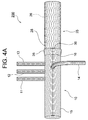
- the aortic treatment device 200 of this embodiment shown in FIG. 4 includes a branched artificial blood vessel portion 10 in which four side tubes 11 to 14 are derived from a main tube 15, and the branched branch
- the stent graft portion 25 connected to the distal side of the branched artificial blood vessel portion 10 by being stitched to the distal end 16 of the artificial blood vessel portion 10 and the distal end 16 of the branched artificial blood vessel portion 10. Rotation that is formed so as to extend to the distal side (see FIG. 4A) and that extends to the proximal side from the distal end 16 of the branched artificial blood vessel 10 by turning (see FIG. 4B).
- a free cuff part 35 is provided.
- the stent graft portion 25 constituting the treatment device 200 of this embodiment includes a self-expanding stent 26 that can be held in a reduced diameter state, and a graft 28 that covers the outer periphery of the stent 26.
- FIG. 4 FIG. 4 (FIGS. 4A and 4B), the stent graft portion 25 is shown in an expanded state, but is mounted in a reduced diameter state on a delivery shaft (not shown) until the diameter is expanded in a living blood vessel. .
- the length of the stent graft part 25 is the same as that of the stent graft part 20 according to the first embodiment.
- the diameter of the stent graft portion 25 is substantially the same as the diameter of the main tube 15 of the branched artificial blood vessel portion 10 (the ratio of the inner diameter of the stent graft portion 25 to the inner diameter of the main tube 15 is 1.0).
- the structures, materials, etc. of the stent 26 and the graft 28 constituting the stent graft portion 25 are the same as those of the stent 21 and the graft 23 constituting the stent graft portion 20 according to the first embodiment.
- the cuff part 35 constituting the treatment device 200 of this embodiment is continuously formed on the distal end 16 of the branched artificial blood vessel part 10 by the same material (knitted fabric) as the branched artificial blood vessel part 10. ing. That is, the branched artificial blood vessel portion 10 and the cuff portion 35 are formed of one tubular knitted fabric. Further, the stent graft portion 25 is connected to the branched artificial blood vessel portion 10 by being stitched to the distal end 16 of the branched artificial blood vessel portion 10. As a result, the treatment device 100 has excellent integrity between the branched artificial blood vessel portion 10 and the cuff portion 35, and reliably leaks blood from between the branched artificial blood vessel portion 10 and the cuff portion 35. Can be avoided.
- the cuff part 35 constituting the treatment device 200 is far from the branch artificial blood vessel part 10 so as to cover the outer periphery of the proximal end part of the stent graft part 25 in a state where it does not rotate.
- the distal end 16 extends distally, and the open end 36 of the cuff portion 35 is located on the distal side of the distal end 16 of the branched artificial blood vessel portion 10.
- the cuff portion 35 has a substantially cylindrical shape in which the inner diameter of the proximal end (the distal end 16 of the branched artificial blood vessel portion 10) and the inner diameter of the open end 36 are substantially equal (the inner diameter of the open end 36 is slightly larger). Is.
- the length of the cuff portion 35 is preferably 5 to 30 mm, and 15 mm is a preferable example.
- the ratio of the inner diameter of the open end 36 to the inner diameter of the base end is less than 1.05, and 1.02 is a preferable example.
- the cuff part 35 can be turned so that it turns over (the inner periphery and the outer periphery are reversed).
- FIG. 4B shows a state in which the cuff portion 35 is turned over.
- the cuff portion 35 extends proximally from the distal end 16 of the branched artificial blood vessel portion 10, and the open end 36 of the cuff portion 35. Is located proximal to the distal end 16 of the branched vascular prosthesis 10.
- the cuff part 35 is coated with collagen, gelatin, or the like, so that blood leakage from the cuff part 35 can be prevented.
- the treatment apparatus 200 of this embodiment can be mounted in the same manner as the treatment apparatus 100 according to the first embodiment using a delivery system (not shown). According to the treatment apparatus 200 of the present embodiment, when the proximal end portion of the distal aorta and the cuff portion 35 are sutured, both can be arranged in a substantially concentric cylindrical shape. A complicated operation such as adjusting the size of the collar, which has been performed when the apparatus is used, is unnecessary, and both can be easily sewn, and no tension remains after the stitching.
- the number of side tubes derived from the main tube of the branched artificial blood vessel portion is not four, but may be one, two, or three.
- the arrangement of branches can be changed as appropriate.
- the horizontal fold may be formed in the graft which comprises a stent graft part, the formation density of a horizontal fold may be small compared with the artificial blood vessel part with a branch.
- the branched artificial blood vessel portion and the cuff portion do not have to be formed by one tubular knitted fabric, for example, the cuff portion is stitched to the distal end of the tubular knitted fabric constituting the branched artificial blood vessel portion. May be. Further, a pleat may be formed in the cuff portion. Further, the ratio of the inner diameter of the stent graft portion to the inner diameter of the main tube of the branched artificial blood vessel portion may be less than 1.0 (for example, 0.8 or more and less than 1.0).
Landscapes
- Health & Medical Sciences (AREA)
- Engineering & Computer Science (AREA)
- Biomedical Technology (AREA)
- Cardiology (AREA)
- Oral & Maxillofacial Surgery (AREA)
- Transplantation (AREA)
- Heart & Thoracic Surgery (AREA)
- Vascular Medicine (AREA)
- Life Sciences & Earth Sciences (AREA)
- Animal Behavior & Ethology (AREA)
- General Health & Medical Sciences (AREA)
- Public Health (AREA)
- Veterinary Medicine (AREA)
- Gastroenterology & Hepatology (AREA)
- Pulmonology (AREA)
- Prostheses (AREA)
Abstract
主管(15)から側管(11)~(14)が派生してなる分枝付き人工血管部(10)と、分枝付き人工血管部(10)の遠位側に縫合により連結されたステントグラフト部(20)と、分枝付き人工血管部(10)の遠位端(16)から遠位側に延びるよう形成され、分枝付き人工血管部(10)の遠位端(16)から近位側に延びるような状態に翻転自在であるスカート状のカフ部(30)とを備えている大動脈治療装置である。この大動脈治療装置によれば、分枝付き人工血管部により大動脈弓部を置換するとともに、遠位側大動脈にステントグラフト部を留置することができ、分枝付き人工血管部と、遠位側大動脈との吻合を、従来の装置と比較して容易に行なうことができる。
Description
本発明は、胸部大動脈における疾患を治療するための治療装置に関する。
大動脈瘤や大動脈解離など、胸部大動脈における疾患を治療する方法として、人工血管置換術およびステントグラフト内挿術が行なわれている。
ここに、大動脈弓部を置換する人工血管置換術に使用する人工血管として、4本の側管が派生してなる分枝付き人工血管が知られている(下記特許文献1)
他方、ステントグラフト内挿術に使用するステントグラフトとしては種々のものが知られており、例えば、OSG(Open Stent Graft)法による治療の際の利便性を向上させることが可能な構造のステントグラフトが本出願人により提案されている(下記特許文献2)。
他方、ステントグラフト内挿術に使用するステントグラフトとしては種々のものが知られており、例えば、OSG(Open Stent Graft)法による治療の際の利便性を向上させることが可能な構造のステントグラフトが本出願人により提案されている(下記特許文献2)。
最近、手技の効率化を企図して、4本の側管が派生してなる分枝付き人工血管と、ステントグラフトとが縫合されて一体化された構造の大動脈治療装置が紹介されている。
図5は、そのような治療装置を示す説明図であり、この治療装置1は、分枝付き人工血管部3と、その遠位側に縫合されたステントグラフト部5と、分枝付き人工血管部3とステントグラフト部5の縫合部に装着されたフランジ状のカラー7とを有している。
図5は、そのような治療装置を示す説明図であり、この治療装置1は、分枝付き人工血管部3と、その遠位側に縫合されたステントグラフト部5と、分枝付き人工血管部3とステントグラフト部5の縫合部に装着されたフランジ状のカラー7とを有している。
この治療装置1は、図示しないデリバリシステムを使用して次のようにして装着される。先ず、大動脈弓部切除後の離断部から、縮径状態のステントグラフト部5を、生体血管である遠位側大動脈(大動脈下行部)に挿入し、フランジ状のカラー7によって遠位側大動脈の近位端部(前記離断部)の開口を塞ぐようにして、治療装置1を配置する。
次に、ステントグラフト部5を拡径させることにより遠位側大動脈の内壁と密着させ、必要に応じてその一部を切り取ることによりカラー7のサイズを調整し、適切なサイズとされたカラー7と、遠位側大動脈の近位端部とを縫合することによって、遠位側大動脈と分枝付き人工血管部3とを吻合する。その後、分枝付き人工血管部3の近位端部と、生体血管である近位側大動脈(大動脈上行部)とを縫合することによって、分枝付き人工血管部3と近位側大動脈とを吻合する。
しかしながら、上記のような治療装置では、患者によって端面形状が異なる遠位側大動脈の近位端部と、フランジ状のカラーとの位置合わせをし、互いの形状やサイズを整えながら両者を縫合する手技はきわめて困難であり、縫合後においてテンションが残りやすいという問題がある。
また、大動脈瘤や大動脈解離などの病変を含む遠位側大動脈の内径は、患者による個人差があり、上記のような治療装置では、遠位側大動脈の内壁にステントグラフト部を十分に密着させることができない場合がある。
本発明は、以上のような事情に基いてなされたものである。
本発明の目的は、分枝付き人工血管部により大動脈弓部を置換するとともに、遠位側大動脈にステントグラフト部を留置することができ、分枝付き人工血管部と、遠位側大動脈との吻合を、従来の装置と比較して容易に行なうことのできる大動脈治療装置を提供することにある。
本発明の目的は、分枝付き人工血管部により大動脈弓部を置換するとともに、遠位側大動脈にステントグラフト部を留置することができ、分枝付き人工血管部と、遠位側大動脈との吻合を、従来の装置と比較して容易に行なうことのできる大動脈治療装置を提供することにある。
本発明の他の目的は、従来の治療装置を構成するステントグラフト部では密着性が不十分である遠位側大動脈の内壁に対しても、十分に密着させることのできるステントグラフト部を備えた大動脈治療装置を提供することにある。
(1)本発明の大動脈治療装置は、少なくとも1本の側管が主管から派生してなる分枝付き人工血管部と、
前記分枝付き人工血管部の遠位側に連結されたステントグラフト部と、
前記分枝付き人工血管部の遠位端から遠位側に延びるよう形成され、前記分枝付き人工血管部の前記遠位端から近位側に延びる状態になるように翻転自在である、円筒状またはスカート状のカフ部とを備えていることを特徴とする。
前記分枝付き人工血管部の遠位側に連結されたステントグラフト部と、
前記分枝付き人工血管部の遠位端から遠位側に延びるよう形成され、前記分枝付き人工血管部の前記遠位端から近位側に延びる状態になるように翻転自在である、円筒状またはスカート状のカフ部とを備えていることを特徴とする。
このような構成の治療装置によれば、カフ部を翻転させ、翻転した状態のカフ部の開口端の位置が遠位側大動脈の近位端の位置と略一致するまで、縮径状態のステントグラフト部を遠位側大動脈に挿入し、当該ステントグラフト部を拡径させて遠位側大動脈に留置させた後、遠位側大動脈の近位端部と、翻転した状態のカフ部とを縫合することによって、遠位側大動脈と分枝付き人工血管部とを吻合することができる。
ここに、遠位側大動脈の近位端部とカフ部とを縫合する際には、両者を、略同心円筒状に配置することができるので、フランジ状のカラーを備えた従来の治療装置と比較して、両者を縫合する手技は格段に容易であり、また、縫合後においてテンションが残ることもない。
(2)本発明の大動脈治療装置において、前記分枝付き人工血管部は、4本の側管が主管から派生してなることが好ましい。
(3)本発明の大動脈治療装置において、前記カフ部は、前記分枝付き人工血管部と同一の材料により前記分枝付き人工血管部の前記遠位端に連続して形成され(すなわち、前記分枝付き人工血管部と前記カフ部とが共通の管状編織物により形成され)、前記ステントグラフト部は、前記分枝付き人工血管部の前記遠位端に縫合されることにより、前記分枝付き人工血管部に連結されていることが好ましい。
このような構成の治療装置によれば、分枝付き人工血管部とカフ部との一体性を更に向上させることができる。
(4)本発明の大動脈治療装置において、前記分枝付き人工血管部の前記主管の内径に対する前記ステントグラフト部の内径の比率が1.01~1.5であることが好ましい。
このような構成の治療装置によれば、前記内径の比率が1.01以上であることにより、従来の治療装置では、ステントグラフト部の密着性が不十分であった遠位側大動脈の内壁に対しても、ステントグラフト部の十分な密着性を確保することができる。
(5)本発明の大動脈治療装置において、前記カフ部は、その長さが5~30mm、基端
の内径に対する開口端の内径の比率が1.05~1.3のスカート状であることが好ましい。
の内径に対する開口端の内径の比率が1.05~1.3のスカート状であることが好ましい。
このような構成の治療装置によれば、前記内径の比率が1.3以下のスカート状であることにより、遠位側大動脈の近位端部との縫合をより容易に行うことができる。
また、前記内径の比率が1.05以上であることにより、遠位側大動脈の近位端の形状(サイズ)が大きくなっていたとしても容易に縫合を行なうことができる。また、カフ部の翻転操作も容易である。
また、前記内径の比率が1.05以上であることにより、遠位側大動脈の近位端の形状(サイズ)が大きくなっていたとしても容易に縫合を行なうことができる。また、カフ部の翻転操作も容易である。
(6)本発明の大動脈治療装置において、前記分枝付き人工血管部および前記カフ部には血液漏出を防止するための被覆処理が施され、前記ステントグラフト部には、そのような被覆処理が施されていないことが好ましい。
このような構成の治療装置によれば、被覆処理が施された分枝付き人工血管部およびカフ部における血液漏出を防止することができるとともに、被覆処理が施されていないステントグラフト部は、柔軟であるために縮径しやすく、血管とのフィッテング性が良好で、生体組織との親和性にも優れている。また、縮径状態で長期にわたり保存した後でも拡径動作に悪影響がなく、保存安定性にも優れている。
本発明の治療装置によれば、分枝付き人工血管部により大動脈弓部を置換できるとともに、遠位側大動脈にステントグラフト部を留置することができ、分枝付き人工血管部と遠位側大動脈との吻合を、従来の治療装置と比較して容易に行なうことができる。
また、分枝付き人工血管部の前記主管の内径に対して1.01倍以上の内径を有するステントグラフト部を備えた本発明の治療装置によれば、従来の治療装置を構成するステントグラフト部では十分に密着させることのできなかった遠位側大動脈の内壁に対しても、本発明の治療装置を構成するステントグラフト部を十分に密着させることができる。
<第1実施形態>
以下、本発明の大動脈治療装置の一実施形態について詳細に説明する。
図1(図1Aおよび図1B)に示すこの実施形態の大動脈治療装置100は、4本の側管11~14が主管15から派生してなる分枝付き人工血管部10と、この分枝付き人工血管部10の遠位端16に縫合されることにより当該分枝付き人工血管部10の遠位側に連結されたステントグラフト部20と、分枝付き人工血管部10の遠位端16から遠位側に延びるように形成され、翻転することによって分枝付き人工血管部10の遠位端16か
ら近位側に延びるような状態になる、翻転自在なスカート状のカフ部30とを備えている。
以下、本発明の大動脈治療装置の一実施形態について詳細に説明する。
図1(図1Aおよび図1B)に示すこの実施形態の大動脈治療装置100は、4本の側管11~14が主管15から派生してなる分枝付き人工血管部10と、この分枝付き人工血管部10の遠位端16に縫合されることにより当該分枝付き人工血管部10の遠位側に連結されたステントグラフト部20と、分枝付き人工血管部10の遠位端16から遠位側に延びるように形成され、翻転することによって分枝付き人工血管部10の遠位端16か
ら近位側に延びるような状態になる、翻転自在なスカート状のカフ部30とを備えている。
本実施形態の治療装置100を構成する分枝付き人工血管部10は、主管15と、この主管15から派生してなる4本の側管11~14を有してなる。
主管15および側管11~14は、管状編織物から構成されている。
主管15および側管11~14には、横ヒダが形成されており、伸縮や曲がりに強くて耐キンク性に優れ、人体の血管形状にも適合しやすい。
主管15および側管11~14は、管状編織物から構成されている。
主管15および側管11~14には、横ヒダが形成されており、伸縮や曲がりに強くて耐キンク性に優れ、人体の血管形状にも適合しやすい。
主管15の長さ(自由長)は100~400mmであることが好ましく、好適な一例を示せば210mmとされる。
主管15の内径は16~36mmであることが好ましく、好適な一例を示せば26mmとされる。
主管15の内径は16~36mmであることが好ましく、好適な一例を示せば26mmとされる。
主管15から派生している側管11~14のうち、3本の側管11~13は一群を形成しており、この群からずれて側管14が配置されている。
側管11~14の長さは50~300mmであることが好ましく、好適な一例を示せば210mmとされる。
側管11の内径は5~14mmであることが好ましく、好適な一例を示せば11mmとされる。
側管12~13の内径は5~12mmであることが好ましく、好適な一例を示せば、それぞれ9mmとされる。
側管14の内径は8~12mmであることが好ましく、好適な一例を示せば9mmとされる。
側管11の内径は5~14mmであることが好ましく、好適な一例を示せば11mmとされる。
側管12~13の内径は5~12mmであることが好ましく、好適な一例を示せば、それぞれ9mmとされる。
側管14の内径は8~12mmであることが好ましく、好適な一例を示せば9mmとされる。
分枝付き人工血管部10(主管15および側管11~14)を構成する管状編織物としては、熱可塑性樹脂繊維の織物または編物からなる管状物を用いることができ、熱可塑性樹脂繊維の平織物を好適に用いることができる。管状編織物の壁厚としては1mm以下であることが好ましく、更に好ましくは0.3~0.7mmである。
熱可塑性樹脂繊維を形成する熱可塑性樹脂としては、ポリエチレン、ポリプロピレン、エチレン-α-オレフィン共重合体などのポリオレフィン、ポリアミド、ポリウレタン、ポリエチレンテレフタレート,ポリブチレンテレフタレート,ポリシクロヘキサンテレフタレート,ポリエチレン-2,6-ナフタレートなどのポリエステル、PTFEやETFEなどのフッ素樹脂などを挙げることができる。これらのうち、化学的に安定で耐久性が良好で、組織反応の少ない、ポリエチレンテレフタレートなどのポリエステル、PTFEやETFEなどのフッ素樹脂が好ましく、特に好ましくは、重量平均分子量1万~20万、特に重量平均分子量1.5万~10万のポリエステルである。
分枝付き人工血管部10はコラーゲンやゼラチン等で被覆処理されており、これにより、分枝付き人工血管部10からの血液漏出を防止することができる。
本実施形態の治療装置100を構成するステントグラフト部20は、縮径状態で保持することができる自己拡張型のステント21と、このステント21の外周を覆うグラフト23とを備えている。
図1(図1Aおよび図1B)では、ステントグラフト部20を拡径状態で示しているが、生体血管内で拡径されるまでは、デリバリシャフト(図示省略)に縮径状態で搭載されている。
ステントグラフト部20の長さは60~210mmであることが好ましく、好適な一例を示せば110mmとされる。
図1(図1Aおよび図1B)に示すように、拡径状態のステントグラフト部20の径は、分枝付き人工血管部10の主管15の径よりも大きくなっている。
ここに、ステントグラフト部20の内径は16~39mmであることが好ましく、好適な一例を示せば30mmとされる。
ここに、ステントグラフト部20の内径は16~39mmであることが好ましく、好適な一例を示せば30mmとされる。
また、分枝付き人工血管部10の主管15の内径に対するステントグラフト部20の内径の比率は1.01~1.5であることが好ましく、好適な一例を示せば1.15(30mm/26mm)である。
ステントグラフト部20の内径が主管15の内径の1.01倍以上であることにより、従来の治療装置では、ステントグラフト部の密着性が不十分であった遠位側大動脈の内壁に対しても、ステントグラフト部20を十分に密着させることができる。
ステントグラフト部20の内径が主管15の内径の1.01倍以上であることにより、従来の治療装置では、ステントグラフト部の密着性が不十分であった遠位側大動脈の内壁に対しても、ステントグラフト部20を十分に密着させることができる。
ステントグラフト部20を構成するステント21の構造は特に限定されず、ジグザグ状の線材からなる筒状構造体、1または複数の線材の編物、織物または組物、あるいはこれらを複数組み合わせた筒状の構造体、金属製の板状または筒状の構造体をレーザー加工などで加工した筒状構造体などを例示することができる。
ステント21を構成する線材および金属製の筒状の構造体の材料としては、ステンレス、タンタル、チタン、白金、金、タングステンなど、Ni-Ti系、Cu-Al-Ni系、Cu-Zn-Al系などの形状記憶合金などの金属線材などを用いることができ、これらの表面に金、白金などをメッキなどの手段で被覆したものであってもよい。
ステント21を構成する線材の径は特に限定されないが、0.08~1mmであることが好ましい。
ステント21を構成する金属製の筒状の構造体の厚さは特に限定されないが、0.08~1mmであることが好ましい。
ステント21を構成する金属製の筒状の構造体の厚さは特に限定されないが、0.08~1mmであることが好ましい。
ステントグラフト部20を構成するグラフト23としては、熱可塑性樹脂を押出成形、ブロー成形などの成形方法で円筒状に形成したもの、円筒状に形成した熱可塑性樹脂の繊維の編織物、円筒状に形成した熱可塑性樹脂の不織布、円筒状に形成した熱可塑性樹脂のシートや多孔質シートなどを用いることができる。
なお、グラフト23には横ヒダが形成されておらず、これにより、血管内壁に対する密着性が十分に確保されている。
グラフト23を構成する熱可塑性樹脂としては、分枝付き人工血管部10(管状編織物)を構成する熱可塑性樹脂繊維を形成するものとして例示した熱可塑性樹脂を挙げることができる。
ステントグラフト部20(グラフト23)には、分枝付き人工血管部10に施された抗血栓性材料による被覆処理は施されていない。
被覆処理が施されていないステントグラフト部20は、柔軟であるため縮径しやすく、血管とのフィッテング性が良好で、生体組織との親和性にも優れている。また、縮径状態で長期間保存した後の拡径動作に悪影響を及ぼすこともない。
被覆処理が施されていないステントグラフト部20は、柔軟であるため縮径しやすく、血管とのフィッテング性が良好で、生体組織との親和性にも優れている。また、縮径状態で長期間保存した後の拡径動作に悪影響を及ぼすこともない。
本実施形態の治療装置100を構成するカフ部30は、分枝付き人工血管部10と同一
の材料(編織物)により、分枝付き人工血管部10の遠位端16に連続して形成されている。
すなわち、分枝付き人工血管部10とカフ部30とは1つの管状編織物によって形成されている。また、ステントグラフト部20は、分枝付き人工血管部10の遠位端16に縫合されることにより、分枝付き人工血管部10に連結されている。
これにより、治療装置100は、分枝付き人工血管部10とカフ部30との一体性に優れたものとなり、分枝付き人工血管部10とカフ部30との間からの血液の漏れを確実に回避することができる。
の材料(編織物)により、分枝付き人工血管部10の遠位端16に連続して形成されている。
すなわち、分枝付き人工血管部10とカフ部30とは1つの管状編織物によって形成されている。また、ステントグラフト部20は、分枝付き人工血管部10の遠位端16に縫合されることにより、分枝付き人工血管部10に連結されている。
これにより、治療装置100は、分枝付き人工血管部10とカフ部30との一体性に優れたものとなり、分枝付き人工血管部10とカフ部30との間からの血液の漏れを確実に回避することができる。
図1Aに示すように、治療装置100を構成するカフ部30は、翻転していない状態では、ステントグラフト部20の近位端部の外周を覆うように、分枝付き人工血管部10の遠位端16から遠位側に延びており、カフ部30の開口端31は、分枝付き人工血管部10の遠位端16の遠位側に位置している。
カフ部30は、その基端(分枝付き人工血管部10の遠位端16)の内径より開口端31の内径が大きいスカート状である。
ここに、カフ部30(前記管状編織物の拡径部分)の長さとしては5~30mmであることが好ましく、好適な一例を示せば15mmである。
ここに、カフ部30(前記管状編織物の拡径部分)の長さとしては5~30mmであることが好ましく、好適な一例を示せば15mmである。
基端におけるカフ部30の内径は、分枝付き人工血管部10の主管15の内径と同一である。
開口端31におけるカフ部30の内径は16~47mmであることが好ましく、好適な一例を示せば28mmである。
また、カフ部30の基端の内径(分枝付き人工血管部10の主管15の内径)に対する開口端31の内径の比率は1.05~1.3であることが好ましく、好適な一例を示せば1.08(28mm/26mm)である。
開口端31におけるカフ部30の内径は16~47mmであることが好ましく、好適な一例を示せば28mmである。
また、カフ部30の基端の内径(分枝付き人工血管部10の主管15の内径)に対する開口端31の内径の比率は1.05~1.3であることが好ましく、好適な一例を示せば1.08(28mm/26mm)である。
内径の比率が1.05以上であることにより、遠位側大動脈の近位端の形状(サイズ)が大きくなっていたとしても容易に縫合を行なうことができる。また、カフ部の翻転操作も容易である。
なお、内径の比率が過大(開口端31の内径>>基端の内径)になると、遠位側大動脈の近位端部との縫合が困難になるが、内径の比率が1.3以下であることにより、遠位側大動脈の近位端部との縫合を容易に行うことができる。
なお、内径の比率が過大(開口端31の内径>>基端の内径)になると、遠位側大動脈の近位端部との縫合が困難になるが、内径の比率が1.3以下であることにより、遠位側大動脈の近位端部との縫合を容易に行うことができる。
カフ部30は、めくれる(内周と外周が逆になる)ように翻転させることができる。
図1Bは、カフ部30が翻転した状態を示しており、翻転後のカフ部30は、分枝付き人工血管部10の遠位端16から近位側に延びており、カフ部30の開口端31は、分枝付き人工血管部10の遠位端16の近位側に位置している。
図1Bは、カフ部30が翻転した状態を示しており、翻転後のカフ部30は、分枝付き人工血管部10の遠位端16から近位側に延びており、カフ部30の開口端31は、分枝付き人工血管部10の遠位端16の近位側に位置している。
カフ部30は、コラーゲンやゼラチン等で被覆処理されており、これにより、カフ部30からの血液漏出を防止することができる。
本実施形態の治療装置100は、図示しないデリバリシステムを使用して次のようにして装着される。
先ず、カフ部30を翻転させた状態で、縮径状態のステントグラフト部20を、大動脈弓部切除後の離断部から、遠位側大動脈(大動脈下行部)に挿入し、翻転しているカフ部30の開口端31の位置を遠位側大動脈の近位端の位置と略一致させる。次に、ステントグラフト部20を拡径させて遠位側大動脈に留置させる。
その後、図2に示すように、遠位側大動脈90の近位端部と、カフ部30とを、縫合糸40で縫合することによって、遠位側大動脈90と分枝付き人工血管部10とを吻合する
。
先ず、カフ部30を翻転させた状態で、縮径状態のステントグラフト部20を、大動脈弓部切除後の離断部から、遠位側大動脈(大動脈下行部)に挿入し、翻転しているカフ部30の開口端31の位置を遠位側大動脈の近位端の位置と略一致させる。次に、ステントグラフト部20を拡径させて遠位側大動脈に留置させる。
その後、図2に示すように、遠位側大動脈90の近位端部と、カフ部30とを、縫合糸40で縫合することによって、遠位側大動脈90と分枝付き人工血管部10とを吻合する
。
図2および図3に示すように、遠位側大動脈90の近位端部とカフ部30とを縫合する際には、両者を、略同心円筒状に配置することができるので、従来の治療装置を使用する際に行っていた、カラーのサイズを調整する等の煩雑な操作も不要であり、両者を容易に縫合することができ、また、縫合後においてテンションが残ることもない。
その後、分枝付き人工血管部10の近位端部と、近位側大動脈(大動脈上行部)とを縫合することによって、分枝付き人工血管部10と近位側大動脈とを吻合する。
<第2実施形態>
次に、本発明の人工血管の他の実施形態について詳細に説明する。
なお、図4(図4Aおよび図4B)に示すこの実施形態において、第1実施形態と同一の構成要素については、図1(図1Aおよび図1B)と同一の符号を付して、その説明を省略する。
次に、本発明の人工血管の他の実施形態について詳細に説明する。
なお、図4(図4Aおよび図4B)に示すこの実施形態において、第1実施形態と同一の構成要素については、図1(図1Aおよび図1B)と同一の符号を付して、その説明を省略する。
図4(図4Aおよび図4B)に示すこの実施形態の大動脈治療装置200は、4本の側管11~14が主管15から派生してなる分枝付き人工血管部10と、この分枝付き人工血管部10の遠位端16に縫合されることにより当該分枝付き人工血管部10の遠位側に連結されたステントグラフト部25と、分枝付き人工血管部10の遠位端16から遠位側に延びるように形成され(図4A参照)、翻転することによって分枝付き人工血管部10の遠位端16から近位側に延びるような状態(図4B参照)になる、翻転自在なカフ部35とを備えている。
本実施形態の治療装置200を構成するステントグラフト部25は、縮径状態で保持することができる自己拡張型のステント26と、このステント26の外周を覆うグラフト28とを備えている。
図4(図4Aおよび図4B)では、ステントグラフト部25を拡径状態で示しているが、生体血管内で拡径されるまでは、デリバリシャフト(図示省略)に縮径状態で搭載されている。
図4(図4Aおよび図4B)では、ステントグラフト部25を拡径状態で示しているが、生体血管内で拡径されるまでは、デリバリシャフト(図示省略)に縮径状態で搭載されている。
ステントグラフト部25の長さは、第1実施形態に係るステントグラフト部20と同一である。
また、ステントグラフト部25の径は、分枝付き人工血管部10の主管15の径と略同一(主管15の内径に対するステントグラフト部25の内径の比率が1.0)である。
また、ステントグラフト部25の径は、分枝付き人工血管部10の主管15の径と略同一(主管15の内径に対するステントグラフト部25の内径の比率が1.0)である。
ステントグラフト部25を構成するステント26およびグラフト28の構造、材料等は、第1実施形態に係るステントグラフト部20を構成するステント21およびグラフト23と同様である。
本実施形態の治療装置200を構成するカフ部35は、分枝付き人工血管部10と同一の材料(編織物)により、分枝付き人工血管部10の遠位端16に連続して形成されている。
すなわち、分枝付き人工血管部10とカフ部35とは1つの管状編織物によって形成されている。また、ステントグラフト部25は、分枝付き人工血管部10の遠位端16に縫合されることにより、分枝付き人工血管部10に連結されている。
これにより、治療装置100は、分枝付き人工血管部10とカフ部35との一体性に優れたものとなり、分枝付き人工血管部10とカフ部35との間からの血液の漏れを確実に回避することができる。
すなわち、分枝付き人工血管部10とカフ部35とは1つの管状編織物によって形成されている。また、ステントグラフト部25は、分枝付き人工血管部10の遠位端16に縫合されることにより、分枝付き人工血管部10に連結されている。
これにより、治療装置100は、分枝付き人工血管部10とカフ部35との一体性に優れたものとなり、分枝付き人工血管部10とカフ部35との間からの血液の漏れを確実に回避することができる。
図4Aに示すように、治療装置200を構成するカフ部35は、翻転していない状態では、ステントグラフト部25の近位端部の外周を覆うように、分枝付き人工血管部10の遠位端16から遠位側に延びており、カフ部35の開口端36は、分枝付き人工血管部10の遠位端16の遠位側に位置している。
カフ部35は、その基端(分枝付き人工血管部10の遠位端16)の内径と、開口端36の内径とが略等しい(開口端36の内径が僅かに大きい)実質的に円筒状である。
カフ部35の長さとしては5~30mmであることが好ましく、好適な一例を示せば15mmである。
基端の内径に対する開口端36の内径の比率は1.05未満とされ、好適な一例を示せば1.02である。
カフ部35の長さとしては5~30mmであることが好ましく、好適な一例を示せば15mmである。
基端の内径に対する開口端36の内径の比率は1.05未満とされ、好適な一例を示せば1.02である。
カフ部35は、めくれる(内周と外周が逆になる)ように翻転させることができる。
図4Bは、カフ部35が翻転した状態を示しており、カフ部35は、分枝付き人工血管部10の遠位端16から近位側に延びており、カフ部35の開口端36は、分枝付き人工血管部10の遠位端16の近位側に位置している。
カフ部35は、コラーゲンやゼラチン等で被覆処理されており、これにより、カフ部35からの血液漏出を防止することができる。
図4Bは、カフ部35が翻転した状態を示しており、カフ部35は、分枝付き人工血管部10の遠位端16から近位側に延びており、カフ部35の開口端36は、分枝付き人工血管部10の遠位端16の近位側に位置している。
カフ部35は、コラーゲンやゼラチン等で被覆処理されており、これにより、カフ部35からの血液漏出を防止することができる。
本実施形態の治療装置200は、図示しないデリバリシステムを使用して、第1実施形態に係る治療装置100と同様にして装着することができる。
本実施形態の治療装置200によれば、遠位側大動脈の近位端部とカフ部35とを縫合する際には、両者を、略同心円筒状に配置することができるので、従来の治療装置を使用する際に行っていた、カラーのサイズを調整する等の煩雑な操作も不要であり、両者を容易に縫合することができ、また、縫合後においてテンションが残ることもない。
本実施形態の治療装置200によれば、遠位側大動脈の近位端部とカフ部35とを縫合する際には、両者を、略同心円筒状に配置することができるので、従来の治療装置を使用する際に行っていた、カラーのサイズを調整する等の煩雑な操作も不要であり、両者を容易に縫合することができ、また、縫合後においてテンションが残ることもない。
以上、本発明の治療装置の実施形態について説明したが、本発明はこれらの実施形態に限定されるものではなく、種々の変更が可能である。
例えば、分枝付き人工血管部の主管から派生する側管の数は4本ではなく、1本、2本または3本でもよい。また、分枝の配置も適宜変更可能である。
また、ステントグラフト部を構成するグラフトには横ヒダが形成されていてもよいが、横ヒダの形成密度は、分枝付き人工血管部と比較して少なくてよい。
また、分枝付き人工血管部とカフ部は1つの管状編織物により形成されていなくてもよく、例えば、分枝付き人工血管部を構成する管状編織物の遠位端にカフ部を縫合してもよい。また、カフ部にヒダが形成されていてもよい。
また、分枝付き人工血管部の主管の内径に対するステントグラフト部の内径の比率が1.0未満(例えば、0.8以上1.0未満)であってもよい。
100 大動脈治療装置
10 分枝付き人工血管部
11-14 側管
15 主管
16 分枝付き人工血管部の遠位端
20 ステントグラフト部
21 ステント
23 グラフト
30 カフ部
31 カフ部の開口端
200 大動脈治療装置
25 ステントグラフト部
26 ステント
28 グラフト
35 カフ部
36 カフ部の開口端
40 縫合糸
10 分枝付き人工血管部
11-14 側管
15 主管
16 分枝付き人工血管部の遠位端
20 ステントグラフト部
21 ステント
23 グラフト
30 カフ部
31 カフ部の開口端
200 大動脈治療装置
25 ステントグラフト部
26 ステント
28 グラフト
35 カフ部
36 カフ部の開口端
40 縫合糸
Claims (6)
- 少なくとも1本の側管が主管から派生してなる分枝付き人工血管部と、
前記分枝付き人工血管部の遠位側に連結されたステントグラフト部と、
前記分枝付き人工血管部の遠位端から遠位側に延びるよう形成され、前記分枝付き人工血管部の前記遠位端から近位側に延びるように翻転自在である円筒状またはスカート状のカフ部とを備えていることを特徴とする大動脈治療装置。 - 前記分枝付き人工血管部は、4本の側管が主管から派生してなることを特徴とする請求項1に記載の大動脈治療装置。
- 前記カフ部は、前記分枝付き人工血管部と同一の材料により、前記分枝付き人工血管部の前記遠位端に連続して形成され、
前記ステントグラフト部は、前記分枝付き人工血管部の前記遠位端に縫合されることにより、前記分枝付き人工血管部に連結されていることを特徴とする請求項1または2に記載の大動脈治療装置。 - 前記分枝付き人工血管部の前記主管の内径に対する前記ステントグラフト部の内径の比率が1.01~1.5であることを特徴とする請求項1~3の何れかに記載の大動脈治療装置。
- 前記カフ部は、その長さが5~30mm、基端の内径に対する開口端の内径の比率が1.05~1.3のスカート状であることを特徴とする請求項1~4の何れかに記載の大動脈治療装置。
- 前記分枝付き人工血管部および前記カフ部には血液漏出を防止するための被覆処理が施され、前記ステントグラフト部には前記被覆処理が施されていないことを特徴とする請求項1~5の何れかに記載の大動脈治療装置。
Priority Applications (2)
| Application Number | Priority Date | Filing Date | Title |
|---|---|---|---|
| KR1020207025442A KR102394785B1 (ko) | 2018-03-09 | 2018-12-11 | 대동맥 치료 장치 |
| EP18909066.5A EP3763327B1 (en) | 2018-03-09 | 2018-12-11 | Aorta treatment device |
Applications Claiming Priority (2)
| Application Number | Priority Date | Filing Date | Title |
|---|---|---|---|
| JP2018-043445 | 2018-03-09 | ||
| JP2018043445A JP6698262B2 (ja) | 2018-03-09 | 2018-03-09 | 大動脈治療装置 |
Publications (1)
| Publication Number | Publication Date |
|---|---|
| WO2019171694A1 true WO2019171694A1 (ja) | 2019-09-12 |
Family
ID=67845925
Family Applications (1)
| Application Number | Title | Priority Date | Filing Date |
|---|---|---|---|
| PCT/JP2018/045473 Ceased WO2019171694A1 (ja) | 2018-03-09 | 2018-12-11 | 大動脈治療装置 |
Country Status (5)
| Country | Link |
|---|---|
| EP (1) | EP3763327B1 (ja) |
| JP (1) | JP6698262B2 (ja) |
| KR (1) | KR102394785B1 (ja) |
| TW (1) | TWI700079B (ja) |
| WO (1) | WO2019171694A1 (ja) |
Cited By (6)
| Publication number | Priority date | Publication date | Assignee | Title |
|---|---|---|---|---|
| CN110897761A (zh) * | 2019-12-29 | 2020-03-24 | 黄健兵 | 一种新型隔绝主动脉弓部及三分支的覆膜支架型血管组合套件 |
| CN112773558A (zh) * | 2021-01-25 | 2021-05-11 | 大连科万维医疗科技有限公司 | 一种自动止血式免缝合支架血管及其使用方法 |
| CN114288063A (zh) * | 2021-12-02 | 2022-04-08 | 姜建杰 | 带翻转四分叉人工血管降主动脉动脉顺行灌注装置 |
| WO2022077857A1 (zh) * | 2020-10-16 | 2022-04-21 | 江苏百优达生命科技有限公司 | 一种一体式血管支架及输送系统 |
| CN118076771A (zh) * | 2021-10-04 | 2024-05-24 | 赛康特集团有限责任公司 | 整体编织歧管及其形成方法 |
| CN119499004A (zh) * | 2023-08-23 | 2025-02-25 | 先健科技(深圳)有限公司 | 一种血管支架 |
Families Citing this family (1)
| Publication number | Priority date | Publication date | Assignee | Title |
|---|---|---|---|---|
| CN114767328A (zh) * | 2022-06-22 | 2022-07-22 | 上海微创心脉医疗科技(集团)股份有限公司 | 医用系统及辅助装置 |
Citations (12)
| Publication number | Priority date | Publication date | Assignee | Title |
|---|---|---|---|---|
| JPH07308330A (ja) | 1994-05-17 | 1995-11-28 | Ube Ind Ltd | 分岐人工血管 |
| US20040082989A1 (en) * | 2002-08-20 | 2004-04-29 | Cook Incorporated | Stent graft with improved proximal end |
| JP2004533868A (ja) * | 2001-03-27 | 2004-11-11 | クック インコーポレイティド | 大動脈用グラフト装置 |
| US20060184229A1 (en) * | 2002-06-25 | 2006-08-17 | Scimed Life Systems, Inc. | Implantable prosthesis with displaceable skirt |
| JP2007501091A (ja) * | 2003-05-09 | 2007-01-25 | ボストン サイエンティフィック リミテッド | モジュール式のステントのための裏返し可能なロック機構 |
| US20070038288A1 (en) * | 2002-07-11 | 2007-02-15 | Whye-Kei Lye | Methods and apparatuses for repairing aneurysms |
| US20080195191A1 (en) * | 2005-05-24 | 2008-08-14 | Qiyi Luo | Flexible Stent-Graft |
| JP2012086004A (ja) * | 2010-09-21 | 2012-05-10 | Terumo Corp | 人工血管及び人工血管システム |
| US20130123902A1 (en) * | 2000-05-01 | 2013-05-16 | Endovascular Technolodies, Inc. | Modular graft component junctions |
| US20150039074A1 (en) * | 2009-06-23 | 2015-02-05 | Endospan Ltd. | Vascular prosthesis for treating aneurysms |
| JP2017023464A (ja) | 2015-07-23 | 2017-02-02 | 日本ライフライン株式会社 | ステントグラフト |
| JP2018083082A (ja) * | 2016-11-22 | 2018-05-31 | クック・メディカル・テクノロジーズ・リミテッド・ライアビリティ・カンパニーCook Medical Technologies Llc | A型患者における遠位大動脈弓および下行大動脈を治療するためのグラフト |
Family Cites Families (5)
| Publication number | Priority date | Publication date | Assignee | Title |
|---|---|---|---|---|
| DE112010002277T5 (de) * | 2009-04-23 | 2012-12-13 | Shaun L.W. Samuels | Endovaskuläre Routervorrichtung und Verfahren |
| US8333800B2 (en) * | 2010-04-29 | 2012-12-18 | Medtronic Vascular, Inc. | Mobile external coupling with internal sealing cuff for branch vessel connection |
| US9724186B2 (en) * | 2012-10-10 | 2017-08-08 | Trivascular, Inc. | Endovascular graft for aneurysms involving major branch vessels |
| WO2018032358A1 (en) * | 2016-08-16 | 2018-02-22 | Dalian Corvivo Medical, Co. Ltd | Endoprosthesis having graft portion and stent graft portion |
| US10905541B2 (en) * | 2018-06-04 | 2021-02-02 | Cook Medical Technologies Llc | Branched frozen elephant trunk device and method |
-
2018
- 2018-03-09 JP JP2018043445A patent/JP6698262B2/ja active Active
- 2018-12-11 WO PCT/JP2018/045473 patent/WO2019171694A1/ja not_active Ceased
- 2018-12-11 EP EP18909066.5A patent/EP3763327B1/en active Active
- 2018-12-11 KR KR1020207025442A patent/KR102394785B1/ko active Active
-
2019
- 2019-02-01 TW TW108104023A patent/TWI700079B/zh not_active IP Right Cessation
Patent Citations (12)
| Publication number | Priority date | Publication date | Assignee | Title |
|---|---|---|---|---|
| JPH07308330A (ja) | 1994-05-17 | 1995-11-28 | Ube Ind Ltd | 分岐人工血管 |
| US20130123902A1 (en) * | 2000-05-01 | 2013-05-16 | Endovascular Technolodies, Inc. | Modular graft component junctions |
| JP2004533868A (ja) * | 2001-03-27 | 2004-11-11 | クック インコーポレイティド | 大動脈用グラフト装置 |
| US20060184229A1 (en) * | 2002-06-25 | 2006-08-17 | Scimed Life Systems, Inc. | Implantable prosthesis with displaceable skirt |
| US20070038288A1 (en) * | 2002-07-11 | 2007-02-15 | Whye-Kei Lye | Methods and apparatuses for repairing aneurysms |
| US20040082989A1 (en) * | 2002-08-20 | 2004-04-29 | Cook Incorporated | Stent graft with improved proximal end |
| JP2007501091A (ja) * | 2003-05-09 | 2007-01-25 | ボストン サイエンティフィック リミテッド | モジュール式のステントのための裏返し可能なロック機構 |
| US20080195191A1 (en) * | 2005-05-24 | 2008-08-14 | Qiyi Luo | Flexible Stent-Graft |
| US20150039074A1 (en) * | 2009-06-23 | 2015-02-05 | Endospan Ltd. | Vascular prosthesis for treating aneurysms |
| JP2012086004A (ja) * | 2010-09-21 | 2012-05-10 | Terumo Corp | 人工血管及び人工血管システム |
| JP2017023464A (ja) | 2015-07-23 | 2017-02-02 | 日本ライフライン株式会社 | ステントグラフト |
| JP2018083082A (ja) * | 2016-11-22 | 2018-05-31 | クック・メディカル・テクノロジーズ・リミテッド・ライアビリティ・カンパニーCook Medical Technologies Llc | A型患者における遠位大動脈弓および下行大動脈を治療するためのグラフト |
Non-Patent Citations (1)
| Title |
|---|
| See also references of EP3763327A4 |
Cited By (6)
| Publication number | Priority date | Publication date | Assignee | Title |
|---|---|---|---|---|
| CN110897761A (zh) * | 2019-12-29 | 2020-03-24 | 黄健兵 | 一种新型隔绝主动脉弓部及三分支的覆膜支架型血管组合套件 |
| WO2022077857A1 (zh) * | 2020-10-16 | 2022-04-21 | 江苏百优达生命科技有限公司 | 一种一体式血管支架及输送系统 |
| CN112773558A (zh) * | 2021-01-25 | 2021-05-11 | 大连科万维医疗科技有限公司 | 一种自动止血式免缝合支架血管及其使用方法 |
| CN118076771A (zh) * | 2021-10-04 | 2024-05-24 | 赛康特集团有限责任公司 | 整体编织歧管及其形成方法 |
| CN114288063A (zh) * | 2021-12-02 | 2022-04-08 | 姜建杰 | 带翻转四分叉人工血管降主动脉动脉顺行灌注装置 |
| CN119499004A (zh) * | 2023-08-23 | 2025-02-25 | 先健科技(深圳)有限公司 | 一种血管支架 |
Also Published As
| Publication number | Publication date |
|---|---|
| TWI700079B (zh) | 2020-08-01 |
| JP6698262B2 (ja) | 2020-05-27 |
| JP2019154666A (ja) | 2019-09-19 |
| EP3763327A1 (en) | 2021-01-13 |
| EP3763327B1 (en) | 2024-05-15 |
| KR20200118127A (ko) | 2020-10-14 |
| EP3763327A4 (en) | 2021-04-14 |
| TW201938118A (zh) | 2019-10-01 |
| KR102394785B1 (ko) | 2022-05-09 |
Similar Documents
| Publication | Publication Date | Title |
|---|---|---|
| JP6698262B2 (ja) | 大動脈治療装置 | |
| US10631972B2 (en) | Branched vessel endoluminal device | |
| US5855598A (en) | Expandable supportive branched endoluminal grafts | |
| US9056001B2 (en) | Method of producing low profile stent and graft combination | |
| JP4846590B2 (ja) | ステントグラフト開窓 | |
| CN101945623B (zh) | 用于修补血管畸形的覆膜支架及相关方法 | |
| JP4406649B2 (ja) | 相互接続モジュール関連適用の管腔内プロテーゼ | |
| JP6100995B2 (ja) | 形状適合プロステーシス供給システム及びその配置方法 | |
| US20090138067A1 (en) | Expandable supportive branched endoluminal grafts | |
| US8864819B2 (en) | Stented side branch graft | |
| US8728144B2 (en) | Endoluminal device including a mechanism for proximal or distal fixation, and sealing and methods of use thereof | |
| US20080221668A1 (en) | Expandable supportive branched endoluminal grafts | |
| WO2017121803A1 (en) | Implantable prosthesis for thoracic aortic disease involving aortic valve dysfunction | |
| JPH08509899A (ja) | 自己拡張可能なステントおよびステント−グラフトならびにそれらの使用方法 | |
| JPH0833719A (ja) | 管腔臓器治療具 | |
| US20070219622A1 (en) | Stent-graft structure having one or more stent pockets | |
| JP7214036B2 (ja) | デリバリシャフトおよびデリバリシステム | |
| KR20170120657A (ko) | 스텐트 그래프트 | |
| US20220257363A1 (en) | Bifurcated stent grafts, stents, and methods | |
| JP6960544B2 (ja) | 治療装置 | |
| JP7446407B2 (ja) | デリバリシャフトおよびデリバリシステム | |
| EP3324883B1 (en) | Graft dimpling to improve crimp profile and reduce delivery forces | |
| WO2023281598A1 (ja) | 治療装置 | |
| WO2023281599A1 (ja) | 治療装置 |
Legal Events
| Date | Code | Title | Description |
|---|---|---|---|
| 121 | Ep: the epo has been informed by wipo that ep was designated in this application |
Ref document number: 18909066 Country of ref document: EP Kind code of ref document: A1 |
|
| ENP | Entry into the national phase |
Ref document number: 20207025442 Country of ref document: KR Kind code of ref document: A |
|
| NENP | Non-entry into the national phase |
Ref country code: DE |
|
| WWE | Wipo information: entry into national phase |
Ref document number: 2018909066 Country of ref document: EP |