WO2019172007A1 - 回転電機 - Google Patents
回転電機 Download PDFInfo
- Publication number
- WO2019172007A1 WO2019172007A1 PCT/JP2019/007163 JP2019007163W WO2019172007A1 WO 2019172007 A1 WO2019172007 A1 WO 2019172007A1 JP 2019007163 W JP2019007163 W JP 2019007163W WO 2019172007 A1 WO2019172007 A1 WO 2019172007A1
- Authority
- WO
- WIPO (PCT)
- Prior art keywords
- stator
- frame
- rotor
- electrical machine
- rotating electrical
- Prior art date
- Legal status (The legal status is an assumption and is not a legal conclusion. Google has not performed a legal analysis and makes no representation as to the accuracy of the status listed.)
- Ceased
Links
Images


Classifications
-
- H—ELECTRICITY
- H02—GENERATION; CONVERSION OR DISTRIBUTION OF ELECTRIC POWER
- H02K—DYNAMO-ELECTRIC MACHINES
- H02K9/00—Arrangements for cooling or ventilating
- H02K9/02—Arrangements for cooling or ventilating by ambient air flowing through the machine
-
- H—ELECTRICITY
- H02—GENERATION; CONVERSION OR DISTRIBUTION OF ELECTRIC POWER
- H02K—DYNAMO-ELECTRIC MACHINES
- H02K1/00—Details of the magnetic circuit
- H02K1/06—Details of the magnetic circuit characterised by the shape, form or construction
- H02K1/12—Stationary parts of the magnetic circuit
- H02K1/20—Stationary parts of the magnetic circuit with channels or ducts for flow of cooling medium
-
- H—ELECTRICITY
- H02—GENERATION; CONVERSION OR DISTRIBUTION OF ELECTRIC POWER
- H02K—DYNAMO-ELECTRIC MACHINES
- H02K5/00—Casings; Enclosures; Supports
- H02K5/04—Casings or enclosures characterised by the shape, form or construction thereof
- H02K5/12—Casings or enclosures characterised by the shape, form or construction thereof specially adapted for operating in liquid or gas
-
- H—ELECTRICITY
- H02—GENERATION; CONVERSION OR DISTRIBUTION OF ELECTRIC POWER
- H02K—DYNAMO-ELECTRIC MACHINES
- H02K5/00—Casings; Enclosures; Supports
- H02K5/04—Casings or enclosures characterised by the shape, form or construction thereof
- H02K5/20—Casings or enclosures characterised by the shape, form or construction thereof with channels or ducts for flow of cooling medium
- H02K5/203—Casings or enclosures characterised by the shape, form or construction thereof with channels or ducts for flow of cooling medium specially adapted for liquids, e.g. cooling jackets
-
- H—ELECTRICITY
- H02—GENERATION; CONVERSION OR DISTRIBUTION OF ELECTRIC POWER
- H02K—DYNAMO-ELECTRIC MACHINES
- H02K5/00—Casings; Enclosures; Supports
- H02K5/04—Casings or enclosures characterised by the shape, form or construction thereof
- H02K5/20—Casings or enclosures characterised by the shape, form or construction thereof with channels or ducts for flow of cooling medium
- H02K5/207—Casings or enclosures characterised by the shape, form or construction thereof with channels or ducts for flow of cooling medium with openings in the casing specially adapted for ambient air
-
- H—ELECTRICITY
- H02—GENERATION; CONVERSION OR DISTRIBUTION OF ELECTRIC POWER
- H02K—DYNAMO-ELECTRIC MACHINES
- H02K9/00—Arrangements for cooling or ventilating
- H02K9/02—Arrangements for cooling or ventilating by ambient air flowing through the machine
- H02K9/04—Arrangements for cooling or ventilating by ambient air flowing through the machine having means for generating a flow of cooling medium
Definitions
- the present invention relates to a rotating electrical machine such as a generator or an electric motor.
- stator and coil ends In rotating electrical machines such as large generators and motors that require high output and high-speed rotation, thick high-voltage insulation is provided inside the stator and coil ends, etc. in response to higher output. Since paper is used and the rotor magnet is fixed to the rotating shaft so as to be covered with a ring in response to high-speed rotation, the stator windings and rotor magnets dissipate heat. It becomes difficult and temperature rises easily.
- a water cooling jacket is provided between the frame and the stator, a ventilation path is formed between the water cooling jacket and the frame, and the cooling water is circulated through the water cooling jacket. It has been proposed to cool the stator and the rotor by circulating the air so that it flows through the ventilation path.
- a rotating electrical machine has a gap between a cylindrical frame, a cylindrical stator attached to the inside of the frame, and the stator.
- a cylindrical rotor disposed inside the stator, a rotating shaft attached to the rotor so as to penetrate the rotor, and a rotating shaft attached to the frame
- a second supply port for supplying cooling air to the duct of the stator. And characterized in that it.
- the rotating electrical machine according to the present invention is the above-described rotating electrical machine, wherein the rotating electrical machine is provided with a cooling water supplied so as to be paired near one end and the other end in the middle in the axial direction of the frame. And a cooling water pipe having a discharge port for discharging cooling water close to the end in the axial direction.
- the rotating electrical machine according to the present invention is the above-described rotating electrical machine, wherein the frame is made of an aluminum metal that is cast so as to house the cooling water pipe between an outer peripheral surface and an inner peripheral surface.
- the cooling air supplied to the first supply port circulates near both axial ends inside the frame, While cooling the coil end, etc., the gap is discharged from the discharge port, and the cooling air fed to the second supply port flows through the stator duct and cools the stator from the axial center. Circulates in the gap so that it branches off from the axially central portion toward both ends, flows out of the gap while cooling the inner peripheral surface of the stator and the outer peripheral surface of the rotor, and discharges from the discharge port Is done.
- the rotating electrical machine not only the coil end is cooled, but also the inside of the axially central portion of the stator having the highest temperature is air-cooled from the radially outer side to the radially inner side. Since the inner peripheral surface of the stator and the outer peripheral surface of the rotor can be air-cooled from the central portion in the axial direction toward the end, windings such as the interior of the stator and coil ends can be used for higher output. Even if the rotor is fixed to the rotating shaft so that the magnet is covered with a ring to cope with high speed rotation, the inner part of the stator and the coil end, etc. The magnet portion of the rotor can be effectively cooled to greatly suppress the temperature rise.
- the rotating electrical machine of the present invention it is possible to greatly improve the cooling performance and further increase the output and speed.
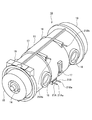
- a cylindrical stator 12 is formed on the inner circumferential surface in the axial direction of the inside of an aluminum metal frame 11 that is a highly heat-conductive material having a hollow cylindrical shape.
- the outer peripheral surface is fixed so as to be coaxial with the frame 11.
- a rotating shaft 14 is arranged in the stator 12 so as to penetrate therethrough coaxially. Both end sides of the rotating shaft 14 are rotatably supported by a pair of annular brackets 15 attached to both end sides of the frame 11, respectively.
- a permanent magnet 13a is disposed on the outer circumferential surface of the rotary shaft 14 in the middle in the axial direction so as to face the inner circumferential surface of the stator 12, and the magnet has a magnetic property.
- a cylindrical ring 13b made of, for example, is fitted so as to fix the permanent magnet 13a to the outer peripheral surface of the rotating shaft 14, and the rotor 13 is constituted by the permanent magnet 13a and the ring 13b.
- the rotating shaft 14 is attached to the rotor 13 so as to penetrate the inside of the rotor 13.
- the rotor 13 is provided inside the stator 12 so as to have a gap G having a predetermined interval between the inner peripheral surface of the stator 12 and the outer peripheral surface of the ring 13b.
- a first supply port 16 and a discharge port 18 for communicating the outside and the inside of the frame 11 are formed to face each other.
- a duct 12 a that is formed along the radial direction in the axial central portion of the stator 12 and communicates with the gap G is communicated with the outside of the frame 11.
- a plurality (two in this embodiment) of second supply ports 17 are formed at equal intervals along the circumferential direction.
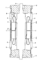
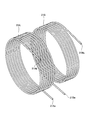
- stainless steel (SUS) cooling water pipes 21 ⁇ / b> A and 21 ⁇ / b> B are located near one end of the frame 11.
- the cooling water pipes 21A and 21B are cast so as to be paired with the other end, and the cooling water pipes 21A and 21B are exposed to the outside of the frame 11 at a lower position near the axial center of the frame 11. It has ports 21Aa and 21Ba, and has discharge ports 21Ab and 21Bb exposed to the outside of the frame 11 at an upper position near the axial end of the frame 11.
- 19 is a coil end.
- the cooling air 1 is fed into the frame 11 from the supply ports 16 and 17, and from the supply ports 21 ⁇ / b> Aa and 21 ⁇ / b> Ba.
- Cooling water 2 is fed into the cooling water pipes 21A and 21B.
- the cooling air 1 fed to the first supply port 16 circulates near both axial ends inside the frame 11 while cooling the coil end 19 and the like.
- the cooling air 1 discharged from the discharge port 18 to the outside of the frame 11 and fed to the second supply port 17 circulates in the duct 12a of the stator 12, and the stator 12 is pivoted. It reaches the gap G while cooling from the central portion in the direction and flows through the gap G so as to branch from the central portion in the axial direction toward both ends, and the inner peripheral surface of the stator 12 and the rotor 13.
- Outflowing from the gap G while cooling the outer peripheral surface merges with the cooling air 1 fed from the first supply port 16, and is discharged from the discharge port 18 to the outside of the frame 11.
- the cooling water 2 fed to the supply ports 21Aa and 21Ba flows through the cooling water pipes 21A and 21B, that is, both end portions from the axially central side with respect to the outer peripheral surface of the stator 12.
- the stator 12 is entirely cooled from the outer peripheral surface through the frame 11 while being spirally circulated toward the respective sides, and discharged from the discharge ports 21Ab and 21Bb.
- the rotating electrical machine 10 not only the coil end 19 is cooled by the cooling air 1 fed to the first supply port 16, but also the cooling fed to the second supply port 17.
- the inside of the axially central portion of the stator 12 having the highest temperature is cooled by air 1 from the radially outer side to the radially inner side, and then the inner peripheral surface of the stator 12 and the outer peripheral surface of the rotor 13.
- the cooling water 2 fed to the supply ports 21Aa and 21Ba the outer peripheral surface of the stator 12 is moved from the axial central portion where the temperature is highest to the end portion. It was made to water-cool toward the part side.
- the rotating electrical machine 10 in the rotating electrical machine 10 according to the present embodiment, thick high-pressure insulating paper is used for the inside of the stator 12 and the winding portion of the coil end 19 or the like in response to higher output, Even if the rotor 13 is fixed to the rotating shaft 14 so as to cover the permanent magnet 13a with the ring 13b in response to the shift, the winding portion such as the inside of the stator 12 and the coil end 19 or the like, The permanent magnet 13a portion of the rotor 13 can be effectively cooled to greatly suppress the temperature rise.
- the cooling performance can be greatly improved, so that higher output and higher speed rotation can be further achieved.
- stator 12 is cooled by circulating the cooling water 2 in parallel through the two cooling water pipes 21A and 21B, without increasing the pressure loss in the cooling water pipes 21A and 21B, Since the flow rate per unit time of the cooling water 2 can be increased, the cooling performance by the cooling water 2 can be greatly improved.
- the rotating electrical machine according to the present invention can greatly improve the cooling performance and further increase the output and the speed, it can be used extremely beneficially industrially.
Landscapes
- Engineering & Computer Science (AREA)
- Power Engineering (AREA)
- Motor Or Generator Cooling System (AREA)
Abstract
円筒形をなすフレーム(11)と、フレーム(11)の内部に取り付けられた円筒形をなす固定子(12)と、固定子(12)との間にギャップ(G)を有するように固定子(12)の内部に配設された円筒形をなす回転子(13)と、回転子(13)の内部を貫通するように回転子(13)に取り付けられた回転軸(14)と、フレーム(11)に取り付けられて回転軸(14)を回転可能に支持するブラケット(15)とを備えている回転電機(10)において、固定子(12)が、軸方向中央部分に径方向へ沿って形成されてギャップ(G)に連通するダクト(12a)を有し、フレーム(11)が、冷却風(1)を軸方向両端寄りの内部に供給する第一の供給口(16)を有すると共に、冷却風(1)を固定子(12)のダクト(12a)へ供給する第二の供給口(17)を有している。
Description
本発明は、発電機や電動機等の回転電機に関する。
高出力化や高速回転化等を要求される大型の発電機や電動機等の回転電機においては、高出力化に対応して、固定子の内部やコイルエンド等の巻線部分に厚手の高圧絶縁紙が使用されると共に、高速回転化に対応して、回転子の磁石が回転軸にリングで覆われるように固定されることから、固定子の巻線部分や回転子の磁石部分が放熱しにくくなり、温度上昇しやすくなっている。
そのため、例えば、下記特許文献1においては、フレームと固定子との間に水冷ジャケットを設けると共に、水冷ジャケットとフレームとの間に通風路を形成し、水冷ジャケットに冷却水を流通させると共に、フレーム内の空気を上記通風路に流通させるように循環させることにより、固定子や回転子を冷却することを提案している。
上述したような大型の回転電機においては、更なる高出力化や高速回転化等の要求に伴って、冷却性能の更なる向上が強く求められている。
前述した課題を解決するための、本発明に係る回転電機は、円筒形をなすフレームと、前記フレームの内部に取り付けられた円筒形をなす固定子と、前記固定子との間にギャップを有するように当該固定子の内部に配設された円筒形をなす回転子と、前記回転子の内部を貫通するように当該回転子に取り付けられた回転軸と、前記フレームに取り付けられて前記回転軸を回転可能に支持するブラケットとを備えている回転電機において、前記固定子が、軸方向中央部分に径方向へ沿って形成されて前記ギャップに連通するダクトを有し、前記フレームが、冷却風を軸方向両端寄りの内部に供給する第一の供給口及び内部の冷却風を外部へ排出する排出口をそれぞれ有すると共に、冷却風を前記固定子の前記ダクトへ供給する第二の供給口を有していることを特徴とする。
また、本発明に係る回転電機は、上述した回転電機において、前記フレームの軸方向中程の一方端寄りと他方端寄りとに対をなすように配設されて冷却水を供給される供給口を軸方向中央寄りに有すると共に冷却水を排出する排出口を軸方向端部寄りに有する冷却水管を備えていることを特徴とする。
また、本発明に係る回転電機は、上述した回転電機において、前記フレームが、前記冷却水管を外周面と内周面との間に内装するように鋳込まれたアルミニウム金属製であることを特徴とする。
本発明に係る回転電機では、第一,二の供給口に冷却風を送給すると、第一の供給口に送給された冷却風が、フレームの内部の軸方向両端寄りを流通して、コイルエンド等を冷却しながら排出口から排出されると共に、第二の供給口に送給された冷却風が、固定子のダクト内を流通して固定子を軸方向中央部分から冷却しながらギャップに到達し、軸方向中央部分から両端側へ向かって分岐するようにギャップ内を流通して固定子の内周面と回転子の外周面とを冷却しながらギャップから流出して排出口から排出される。
このため、本発明に係る回転電機によれば、コイルエンドを冷却するだけでなく、固定子の最も温度の高い軸方向中央部分の内部を径方向外側から径方向内側へ向かって空冷してから固定子の内周面と回転子の外周面とを軸方向中央部分から端部側へ向かって空冷することができるので、高出力化への対応で固定子の内部やコイルエンド等の巻線部分に厚手の高圧絶縁紙を使用したり、高速回転化への対応で磁石をリングで覆うように回転子を回転軸に固定しても、固定子の内部及びコイルエンド等の巻線部分や、回転子の磁石部分を効果的に冷却して、温度上昇を大幅に抑制することができる。
したがって、本発明に係る回転電機によれば、冷却性能を大きく向上させて、高出力化や高速回転化を更に図ることができる。
本発明に係る回転電機の実施形態を図面に基づいて説明するが、本発明は図面に基づいて説明する以下の実施形態のみに限定されるものではない。
〈主な実施形態〉
本発明に係る回転電機の主な実施形態を図1~5に基づいて説明する。
本発明に係る回転電機の主な実施形態を図1~5に基づいて説明する。
図1,2に示すように、内部中空の円筒形をなす高伝熱性材料であるアルミニウム金属製のフレーム11の内部の軸方向中程の内周面には、円筒形をなす固定子12の外周面が当該フレーム11と同軸をなすようにして固定されている。前記固定子12の内部には、回転軸14が同軸をなして貫通するように配設されている。前記回転軸14の両端側は、前記フレーム11の両端側にそれぞれ取り付けられた対をなす環状のブラケット15にそれぞれ回転可能に支持されている。
前記回転軸14の軸方向中程の外周面には、永久磁石13aが前記固定子12の内周面と対向するように当該回転軸14の周方向にわたって配設されると共に、磁性を有する鉄等からなる円筒形のリング13bが当該永久磁石13aを当該回転軸14の外周面に固定するように嵌合しており、当該永久磁石13a及び当該リング13b等により、回転子13が構成されている。言い換えると、前記回転軸14は、前記回転子13の内部を貫通するように当該回転子13に取り付けられているのである。そして、前記回転子13は、前記固定子12の内周面と前記リング13bの外周面との間に規定間隔のギャップGを有するように当該固定子12の内部に設けられている。
前記フレーム11の周面の軸方向両端寄りには、当該フレーム11の外部と内部とを連通させる第一の供給口16と排出口18とが互いに対向するようにそれぞれ形成されている。前記フレーム11の周面の軸方向中程には、前記固定子12の軸方向中央部分に径方向へ沿って形成されて前記ギャップGに連通するダクト12aと当該フレーム11の外部とを連通させる第二の供給口17が、周方向に沿って等間隔で複数(本実施形態では二つ)形成されている。
前記フレーム11の外周面と内周面との間の軸方向中程には、螺旋状をなすステンレス(SUS)製の冷却水管21A,21B(図3参照)が当該フレーム11の一方端寄りと他方端寄りとで対をなして内装されるように鋳込まれており、当該冷却水管21A,21Bは、当該フレーム11の軸方向中央寄りの下方位置に、当該フレーム11の外部へ露出する供給口21Aa,21Baを有し、当該フレーム11の軸方向端部寄りの上方位置に、当該フレーム11の外部へ露出する排出口21Ab,21Bbを有している。
なお、図中、19はコイルエンドである。
このような本実施形態に係る回転電機10においては、図4に示すように、前記供給口16,17から前記フレーム11の内部に冷却風1を送給すると共に、前記供給口21Aa,21Baから前記冷却水管21A,21Bの内部に冷却水2を送給する。
すると、図5に示すように、前記第一の供給口16に送給された冷却風1は、前記フレーム11の内部の軸方向両端寄りを流通して、前記コイルエンド19等を冷却しながら前記排出口18から当該フレーム11の外部へ排出され、前記第二の供給口17に送給された冷却風1は、前記固定子12の前記ダクト12a内を流通して当該固定子12を軸方向中央部分から冷却しながら前記ギャップGに到達し、軸方向中央部分から両端側へ向かって分岐するように当該ギャップG内を流通して当該固定子12の内周面と前記回転子13の外周面とを冷却しながら当該ギャップGから流出し、上記第一の供給口16から送給された冷却風1と合流して上記排出口18から上記フレーム11の外部へ排出される。
他方、前記供給口21Aa,21Baに送給された冷却水2は、前記冷却水管21A,21B内を流通する、すなわち、前記固定子12の外周面に対して軸方向中央側から両方の端部側へ各々向かうように螺旋状に流通しながら前記フレーム11を介して当該固定子12を外周面から全体的に冷却して、前記排出口21Ab,21Bbから排出される。
つまり、本実施形態に係る回転電機10では、前記第一の供給口16に送給する冷却風1により、コイルエンド19を冷却するだけでなく、前記第二の供給口17に送給する冷却風1により、前記固定子12の最も温度の高い軸方向中央部分の内部を径方向外側から径方向内側へ向かって空冷してから当該固定子12の内周面と前記回転子13の外周面とを軸方向中央部分から端部側へ向かって空冷すると共に、前記供給口21Aa,21Baに送給する冷却水2により、上記固定子12の外周面を最も温度の高い軸方向中央部分から端部側へ向かって水冷するようにしたのである。
このため、本実施形態に係る回転電機10においては、高出力化への対応で前記固定子12の内部や前記コイルエンド19等の巻線部分に厚手の高圧絶縁紙を使用したり、高速回転化への対応で前記永久磁石13aを前記リング13bで覆うように前記回転子13を前記回転軸14に固定しても、当該固定子12の内部及び上記コイルエンド19等の巻線部分や、当該回転子13の上記永久磁石13a部分を効果的に冷却して、温度上昇を大幅に抑制することができる。
したがって、本実施形態に係る回転電機10によれば、冷却性能を大きく向上させることができるので、高出力化や高速回転化を更に図ることができる。
また、二本の冷却水管21A,21Bに冷却水2を並列的に流通させて前記固定子12を冷却するようにしたことから、当該冷却水管21A,21B内の圧力損失を増加させることなく、冷却水2の単位時間当たりの流量を増加させることができるので、冷却水2による冷却性能を大きく向上させることができる。
本発明に係る回転電機は、冷却性能を大きく向上させて、高出力化や高速回転化を更に図ることができるので、産業上、極めて有益に利用することができる。
1 冷却風
2 冷却水
10 回転電機
11 フレーム
12 固定子
12a ダクト
13 回転子
13a 永久磁石
13b リング
14 回転軸
15 ブラケット
16 第一の供給口
17 第二の供給口
18 排出口
19 コイルエンド
21A,21B 冷却水管
21Aa,21Ba 供給口
21Ab,21Bb 排出口
G ギャップ
2 冷却水
10 回転電機
11 フレーム
12 固定子
12a ダクト
13 回転子
13a 永久磁石
13b リング
14 回転軸
15 ブラケット
16 第一の供給口
17 第二の供給口
18 排出口
19 コイルエンド
21A,21B 冷却水管
21Aa,21Ba 供給口
21Ab,21Bb 排出口
G ギャップ
Claims (3)
- 円筒形をなすフレームと、
前記フレームの内部に取り付けられた円筒形をなす固定子と、
前記固定子との間にギャップを有するように当該固定子の内部に配設された円筒形をなす回転子と、
前記回転子の内部を貫通するように当該回転子に取り付けられた回転軸と、
前記フレームに取り付けられて前記回転軸を回転可能に支持するブラケットと
を備えている回転電機において、
前記固定子が、軸方向中央部分に径方向へ沿って形成されて前記ギャップに連通するダクトを有し、
前記フレームが、冷却風を軸方向両端寄りの内部に供給する第一の供給口及び内部の冷却風を外部へ排出する排出口をそれぞれ有すると共に、冷却風を前記固定子の前記ダクトへ供給する第二の供給口を有している
ことを特徴とする回転電機。 - 請求項1に記載の回転電機において、
前記フレームの軸方向中程の一方端寄りと他方端寄りとに対をなすように配設されて冷却水を供給される供給口を軸方向中央寄りに有すると共に冷却水を排出する排出口を軸方向端部寄りに有する冷却水管を備えている
ことを特徴とする回転電機。 - 請求項2に記載の回転電機において、
前記フレームが、前記冷却水管を外周面と内周面との間に内装するように鋳込まれたアルミニウム金属製である
ことを特徴とする回転電機。
Priority Applications (4)
| Application Number | Priority Date | Filing Date | Title |
|---|---|---|---|
| US16/978,302 US11025136B2 (en) | 2018-03-09 | 2019-02-26 | Dynamo-electric machine |
| EP19764130.1A EP3764524B1 (en) | 2018-03-09 | 2019-02-26 | Dynamo-electric machine |
| RU2020131483A RU2742819C1 (ru) | 2018-03-09 | 2019-02-26 | Динамоэлектрическая машина |
| CN201980017516.8A CN111819771B (zh) | 2018-03-09 | 2019-02-26 | 电动机器 |
Applications Claiming Priority (2)
| Application Number | Priority Date | Filing Date | Title |
|---|---|---|---|
| JP2018-042614 | 2018-03-09 | ||
| JP2018042614A JP6624223B2 (ja) | 2018-03-09 | 2018-03-09 | 回転電機 |
Publications (1)
| Publication Number | Publication Date |
|---|---|
| WO2019172007A1 true WO2019172007A1 (ja) | 2019-09-12 |
Family
ID=67846661
Family Applications (1)
| Application Number | Title | Priority Date | Filing Date |
|---|---|---|---|
| PCT/JP2019/007163 Ceased WO2019172007A1 (ja) | 2018-03-09 | 2019-02-26 | 回転電機 |
Country Status (6)
| Country | Link |
|---|---|
| US (1) | US11025136B2 (ja) |
| EP (1) | EP3764524B1 (ja) |
| JP (1) | JP6624223B2 (ja) |
| CN (1) | CN111819771B (ja) |
| RU (1) | RU2742819C1 (ja) |
| WO (1) | WO2019172007A1 (ja) |
Cited By (1)
| Publication number | Priority date | Publication date | Assignee | Title |
|---|---|---|---|---|
| US20240204618A1 (en) * | 2021-04-30 | 2024-06-20 | Meidensha Corporation | Rotary machine |
Families Citing this family (5)
| Publication number | Priority date | Publication date | Assignee | Title |
|---|---|---|---|---|
| WO2021187166A1 (ja) * | 2020-03-18 | 2021-09-23 | 株式会社明電舎 | 回転機 |
| JP6912028B1 (ja) * | 2020-03-18 | 2021-07-28 | 株式会社明電舎 | 回転機 |
| JP7266790B1 (ja) | 2021-11-19 | 2023-05-01 | 株式会社明電舎 | 回転電機 |
| EP4485761A1 (en) * | 2023-06-30 | 2025-01-01 | Abb Schweiz Ag | Apparatus and method for cooling |
| BE1032085B1 (nl) * | 2023-10-24 | 2025-05-26 | Atlas Copco Airpower Nv | Behuizing om een permanent-magneet motor van een luchtblower te voorzien van een luchtkoeling |
Citations (7)
| Publication number | Priority date | Publication date | Assignee | Title |
|---|---|---|---|---|
| JPS6370260U (ja) * | 1986-10-23 | 1988-05-11 | ||
| JPH0644378U (ja) * | 1992-11-20 | 1994-06-10 | 株式会社明電舎 | 回転電機 |
| JPH08322188A (ja) * | 1995-05-26 | 1996-12-03 | Meidensha Corp | 強制通風冷却形電動機 |
| JP2002186221A (ja) * | 2000-12-11 | 2002-06-28 | Mitsubishi Heavy Ind Ltd | 発電機における冷却構造 |
| JP2008301646A (ja) | 2007-06-01 | 2008-12-11 | Aichi Electric Co Ltd | モータ冷却装置 |
| JP2011211816A (ja) | 2010-03-30 | 2011-10-20 | Hitachi Ltd | 永久磁石式回転電機及び風力発電システム |
| JP2013207944A (ja) * | 2012-03-29 | 2013-10-07 | Hitachi Automotive Systems Ltd | 車両用回転電機 |
Family Cites Families (17)
| Publication number | Priority date | Publication date | Assignee | Title |
|---|---|---|---|---|
| SU1713024A1 (ru) * | 1989-08-22 | 1992-02-15 | Всесоюзный научно-исследовательский, проектно-конструкторский и технологический институт взрывозащищенного и рудничного электрооборудования | Корпус закрытой электрической машины |
| JPH04180393A (ja) * | 1990-11-14 | 1992-06-26 | Fujitsu General Ltd | 構内電話交換装置 |
| DE19526689A1 (de) * | 1995-07-21 | 1997-01-23 | Abb Management Ag | Rohrgenerator |
| JP2001500353A (ja) * | 1996-08-09 | 2001-01-09 | ザ・ターボ・ゲンセット・カンパニー・リミテッド | 回転電気機械 |
| US5859482A (en) * | 1997-02-14 | 1999-01-12 | General Electric Company | Liquid cooled electric motor frame |
| JP3877899B2 (ja) | 1999-03-09 | 2007-02-07 | 三菱電機株式会社 | 車両用交流発電機 |
| JP2001045713A (ja) * | 1999-07-30 | 2001-02-16 | Hitachi Ltd | 回転電機 |
| DE10122425B4 (de) * | 2001-05-09 | 2006-06-01 | Siemens Ag | Elektrische Maschine |
| DE502004010520D1 (de) * | 2004-07-30 | 2010-01-28 | Brose Fahrzeugteile | Elektromotor |
| JP2006161590A (ja) * | 2004-12-03 | 2006-06-22 | Denso Corp | スタータ |
| DE102006036289B4 (de) * | 2006-08-03 | 2010-04-08 | Siemens Ag | Motorsystem sowie Verfahren zum Betreiben eines Motorsystems |
| JP5470015B2 (ja) * | 2009-12-04 | 2014-04-16 | 株式会社日立製作所 | 回転電機 |
| JP6016230B2 (ja) * | 2012-09-27 | 2016-10-26 | 澤藤電機株式会社 | 発電機 |
| US9461523B2 (en) * | 2013-12-12 | 2016-10-04 | Baldor Electric Company | Two phase gap cooling of an electrical machine |
| KR20160000909A (ko) * | 2014-06-25 | 2016-01-06 | 현대모비스 주식회사 | 수냉식 모터 |
| CN204886564U (zh) * | 2015-05-11 | 2015-12-16 | 哈尔滨电机厂有限责任公司 | 一种直通式冷却贯流水轮发电机通风装置 |
| CN107147260A (zh) * | 2017-07-19 | 2017-09-08 | 沈阳工业大学 | 一种具有混合冷却结构的轴向永磁辅助径向磁阻高速电机 |
-
2018
- 2018-03-09 JP JP2018042614A patent/JP6624223B2/ja active Active
-
2019
- 2019-02-26 US US16/978,302 patent/US11025136B2/en active Active
- 2019-02-26 RU RU2020131483A patent/RU2742819C1/ru active
- 2019-02-26 WO PCT/JP2019/007163 patent/WO2019172007A1/ja not_active Ceased
- 2019-02-26 CN CN201980017516.8A patent/CN111819771B/zh active Active
- 2019-02-26 EP EP19764130.1A patent/EP3764524B1/en active Active
Patent Citations (7)
| Publication number | Priority date | Publication date | Assignee | Title |
|---|---|---|---|---|
| JPS6370260U (ja) * | 1986-10-23 | 1988-05-11 | ||
| JPH0644378U (ja) * | 1992-11-20 | 1994-06-10 | 株式会社明電舎 | 回転電機 |
| JPH08322188A (ja) * | 1995-05-26 | 1996-12-03 | Meidensha Corp | 強制通風冷却形電動機 |
| JP2002186221A (ja) * | 2000-12-11 | 2002-06-28 | Mitsubishi Heavy Ind Ltd | 発電機における冷却構造 |
| JP2008301646A (ja) | 2007-06-01 | 2008-12-11 | Aichi Electric Co Ltd | モータ冷却装置 |
| JP2011211816A (ja) | 2010-03-30 | 2011-10-20 | Hitachi Ltd | 永久磁石式回転電機及び風力発電システム |
| JP2013207944A (ja) * | 2012-03-29 | 2013-10-07 | Hitachi Automotive Systems Ltd | 車両用回転電機 |
Non-Patent Citations (1)
| Title |
|---|
| See also references of EP3764524A4 |
Cited By (1)
| Publication number | Priority date | Publication date | Assignee | Title |
|---|---|---|---|---|
| US20240204618A1 (en) * | 2021-04-30 | 2024-06-20 | Meidensha Corporation | Rotary machine |
Also Published As
| Publication number | Publication date |
|---|---|
| EP3764524B1 (en) | 2022-07-27 |
| JP6624223B2 (ja) | 2019-12-25 |
| CN111819771B (zh) | 2021-07-16 |
| EP3764524A4 (en) | 2021-04-21 |
| EP3764524A1 (en) | 2021-01-13 |
| US20210006131A1 (en) | 2021-01-07 |
| RU2742819C1 (ru) | 2021-02-11 |
| US11025136B2 (en) | 2021-06-01 |
| JP2019161764A (ja) | 2019-09-19 |
| CN111819771A (zh) | 2020-10-23 |
Similar Documents
| Publication | Publication Date | Title |
|---|---|---|
| WO2019172007A1 (ja) | 回転電機 | |
| JP2019161752A (ja) | 回転電機のステータ | |
| JP2006033965A (ja) | ディスク型回転電機のステータ冷却構造 | |
| JP6560033B2 (ja) | 回転電機、並びに回転電機の冷却システム | |
| CN102640400A (zh) | 用于电机的旋转定向冷却剂喷洒装置 | |
| WO2017082023A1 (ja) | 回転電機 | |
| CN103390942B (zh) | 发电机,具体是用于风力涡轮机的发电机 | |
| JP2017192163A (ja) | 全閉形回転電機 | |
| JP2019205254A (ja) | 回転電機 | |
| JP2015012792A (ja) | 回転電機のステータ | |
| JP6944418B2 (ja) | 回転電機および回転子 | |
| JP2014045606A (ja) | 回転電機 | |
| JP2016220395A (ja) | 回転電機 | |
| JP2019154197A (ja) | 回転電機 | |
| JP2010187490A (ja) | 回転電機 | |
| JPS596135B2 (ja) | 突極形回転電機 | |
| JP6473128B2 (ja) | 同期回転電機および界磁巻線端部保持構造 | |
| US11967877B2 (en) | Rotating electric machine | |
| JP2010187489A (ja) | 回転電機 | |
| JP2017200354A (ja) | ブラシレス回転電機 | |
| US2324297A (en) | Dynamoelectric machine | |
| JP2023000723A (ja) | 回転電機用ケース、及び回転電機 | |
| JP7082957B2 (ja) | 回転子冷却構造およびタービン発電機 | |
| KR101758989B1 (ko) | 발전기용 로터 어셈블리 | |
| JP2015159723A (ja) | 回転電機 |
Legal Events
| Date | Code | Title | Description |
|---|---|---|---|
| 121 | Ep: the epo has been informed by wipo that ep was designated in this application |
Ref document number: 19764130 Country of ref document: EP Kind code of ref document: A1 |
|
| NENP | Non-entry into the national phase |
Ref country code: DE |
|
| WWE | Wipo information: entry into national phase |
Ref document number: 2019764130 Country of ref document: EP |