WO2019172079A1 - 光ファイバ - Google Patents
光ファイバ Download PDFInfo
- Publication number
- WO2019172079A1 WO2019172079A1 PCT/JP2019/007869 JP2019007869W WO2019172079A1 WO 2019172079 A1 WO2019172079 A1 WO 2019172079A1 JP 2019007869 W JP2019007869 W JP 2019007869W WO 2019172079 A1 WO2019172079 A1 WO 2019172079A1
- Authority
- WO
- WIPO (PCT)
- Prior art keywords
- optical fiber
- diameter
- core
- trench
- refractive index
- Prior art date
- Legal status (The legal status is an assumption and is not a legal conclusion. Google has not performed a legal analysis and makes no representation as to the accuracy of the status listed.)
- Ceased
Links
Images














Classifications
-
- G—PHYSICS
- G02—OPTICS
- G02B—OPTICAL ELEMENTS, SYSTEMS OR APPARATUS
- G02B6/00—Light guides; Structural details of arrangements comprising light guides and other optical elements, e.g. couplings
- G02B6/02—Optical fibres with cladding with or without a coating
- G02B6/036—Optical fibres with cladding with or without a coating core or cladding comprising multiple layers
- G02B6/03616—Optical fibres characterised both by the number of different refractive index layers around the central core segment, i.e. around the innermost high index core layer, and their relative refractive index difference
- G02B6/03622—Optical fibres characterised both by the number of different refractive index layers around the central core segment, i.e. around the innermost high index core layer, and their relative refractive index difference having 2 layers only
- G02B6/03633—Optical fibres characterised both by the number of different refractive index layers around the central core segment, i.e. around the innermost high index core layer, and their relative refractive index difference having 2 layers only arranged - -
-
- G—PHYSICS
- G02—OPTICS
- G02B—OPTICAL ELEMENTS, SYSTEMS OR APPARATUS
- G02B6/00—Light guides; Structural details of arrangements comprising light guides and other optical elements, e.g. couplings
- G02B6/02—Optical fibres with cladding with or without a coating
-
- G—PHYSICS
- G02—OPTICS
- G02B—OPTICAL ELEMENTS, SYSTEMS OR APPARATUS
- G02B6/00—Light guides; Structural details of arrangements comprising light guides and other optical elements, e.g. couplings
- G02B6/02—Optical fibres with cladding with or without a coating
- G02B6/036—Optical fibres with cladding with or without a coating core or cladding comprising multiple layers
-
- G—PHYSICS
- G02—OPTICS
- G02B—OPTICAL ELEMENTS, SYSTEMS OR APPARATUS
- G02B6/00—Light guides; Structural details of arrangements comprising light guides and other optical elements, e.g. couplings
- G02B6/02—Optical fibres with cladding with or without a coating
- G02B6/02004—Optical fibres with cladding with or without a coating characterised by the core effective area or mode field radius
-
- G—PHYSICS
- G02—OPTICS
- G02B—OPTICAL ELEMENTS, SYSTEMS OR APPARATUS
- G02B6/00—Light guides; Structural details of arrangements comprising light guides and other optical elements, e.g. couplings
- G02B6/02—Optical fibres with cladding with or without a coating
- G02B6/02214—Optical fibres with cladding with or without a coating tailored to obtain the desired dispersion, e.g. dispersion shifted, dispersion flattened
-
- G—PHYSICS
- G02—OPTICS
- G02B—OPTICAL ELEMENTS, SYSTEMS OR APPARATUS
- G02B6/00—Light guides; Structural details of arrangements comprising light guides and other optical elements, e.g. couplings
- G02B6/02—Optical fibres with cladding with or without a coating
- G02B6/036—Optical fibres with cladding with or without a coating core or cladding comprising multiple layers
- G02B6/03616—Optical fibres characterised both by the number of different refractive index layers around the central core segment, i.e. around the innermost high index core layer, and their relative refractive index difference
- G02B6/03638—Optical fibres characterised both by the number of different refractive index layers around the central core segment, i.e. around the innermost high index core layer, and their relative refractive index difference having 3 layers only
- G02B6/0365—Optical fibres characterised both by the number of different refractive index layers around the central core segment, i.e. around the innermost high index core layer, and their relative refractive index difference having 3 layers only arranged - - +
Definitions
- the present invention relates to an optical fiber.
- Non-Patent Document 1 a configuration in which the relative refractive index difference of the core portion with respect to the cladding portion is increased as a small-diameter optical fiber.
- Patent Document 1 the structure which provided the trench layer adjacent to the core part is disclosed.
- the optical fiber disclosed in Non-Patent Document 1 has characteristics such as ITU-T (International Telecommunication Union) It does not satisfy the standard (hereinafter referred to as G.650.2 standard) of the standard single mode optical fiber defined by 650.2. Further, the optical fiber disclosed in Patent Document 1 has G. Although the 650.2 standard is satisfied, the outer diameter (fiber diameter) of the clad portion is about 100 ⁇ m to 125 ⁇ m, which is insufficient in terms of the diameter reduction that will become increasingly demanded in the future. Further, when the diameter of the optical fiber is reduced, the leakage loss increases, but the leakage loss is suppressed to a sufficiently low level, and an optical fiber with a reduced diameter has not been disclosed.
- ITU-T International Telecommunication Union
- the present invention has been made in view of the above, and an object thereof is to provide a small-diameter optical fiber in which leakage loss is suppressed.
- an optical fiber according to an aspect of the present invention is located on a glass core and an outer periphery of the core, and is lower than the refractive index of the core.
- a clad portion made of glass having a refractive index, and an outer diameter of the clad portion is less than 100 ⁇ m, and a relative refractive index difference of the core portion with respect to the clad portion is 0.32% to 0.40%. It is characterized by that.
- the optical fiber according to an aspect of the present invention is characterized in that the core portion has a core diameter of 7 ⁇ m to 10 ⁇ m.
- the relative refractive index difference of the core portion is 0.335% to 0.375%, and the core diameter of the core portion is 8.2 ⁇ m to 9.2 ⁇ m.
- the relative refractive index difference of the core portion is 0.37% to 0.395%, and the core diameter of the core portion is 7.6 ⁇ m to 8.3 ⁇ m.
- the optical fiber which concerns on 1 aspect of this invention WHEREIN is located in the adjacent area
- a non-adjacent region, and the adjacent region is made of pure quartz glass.
- the optical fiber according to one aspect of the present invention is characterized in that the non-adjacent region is made of pure silica glass.
- the optical fiber according to one aspect of the present invention is characterized in that the non-adjacent region has a trench layer having a refractive index lower than that of the adjacent region.
- the optical fiber according to an aspect of the present invention is characterized in that b / a is 2 or more when the core diameter of the core portion is 2a and the inner diameter of the trench layer is 2b.
- the optical fiber according to an aspect of the present invention is characterized in that b / a is 3 or more when the core diameter of the core portion is 2a and the inner diameter of the trench layer is 2b.
- the width (cb) of the trench layer is a. It is characterized by 0.2 to 1 times.
- the optical fiber according to an aspect of the present invention is characterized in that a relative refractive index difference with respect to the adjacent region of the trench layer is ⁇ 0.4% or less.
- the clad portion includes a trench layer adjacent to the core portion, and a relative refractive index difference of the trench layer with respect to the clad portion other than the trench layer is ⁇ 0.1. % Or more and less than 0%.
- the optical fiber according to one embodiment of the present invention is characterized in that a mode field diameter at a wavelength of 1310 nm is 8.6 ⁇ m to 9.5 ⁇ m.
- the optical fiber according to one embodiment of the present invention is characterized in that a bending loss at a wavelength of 1550 nm when bent at a diameter of 60 mm is 5.3 ⁇ 10 ⁇ 3 dB / m or less.
- An optical fiber according to one embodiment of the present invention has a zero dispersion wavelength of 1300 nm to 1324 nm, and a dispersion slope at the zero dispersion wavelength of 0.092 ps / nm 2 / km or less.
- the optical fiber according to one embodiment of the present invention has a cable cutoff wavelength of 1260 nm or less.
- the optical fiber according to one embodiment of the present invention is characterized in that a mode field diameter at a wavelength of 1550 nm is 9.5 ⁇ m or more.
- the optical fiber according to one embodiment of the present invention has a cable cutoff wavelength of 1530 nm or less.
- FIG. 1 is a schematic cross-sectional view of an optical fiber according to the first embodiment.
- FIG. 2A is a diagram showing a refractive index profile of the optical fiber shown in FIG. 2B is a diagram showing a refractive index profile of the optical fiber shown in FIG.
- FIG. 3 is a diagram showing the relationship of ⁇ 1 and the critical fiber diameter with respect to the core diameter.
- FIG. 4 is a diagram illustrating a refractive index profile of the optical fiber according to the second embodiment.
- FIG. 5 is a diagram showing the relationship between chromatic dispersion and MFD with respect to the distance between the trench layer and the core portion.
- FIG. 6 is a diagram illustrating a relationship between the amount of change in MFD and the amount of change in cutoff wavelength with respect to ⁇ 3 when the core portion and the trench layer are adjacent to each other.
- FIG. 7 is a diagram illustrating a measurement result of transmission loss.
- FIG. 8A is a diagram showing the relationship of the zero dispersion wavelength with respect to the trench position.
- FIG. 8B is a diagram showing the relationship of the dispersion slope to the trench position.
- FIG. 8C is a diagram showing the relationship of the zero dispersion wavelength with respect to the trench position.
- FIG. 8D is a diagram showing the relationship of the dispersion slope to the trench position.
- FIG. 9A is a diagram showing the relationship of the zero dispersion wavelength with respect to the trench position.
- FIG. 9B is a diagram showing the relationship of the dispersion slope to the trench position.
- FIG. 9C is a diagram showing the relationship of the zero dispersion wavelength with respect to the trench position.
- FIG. 9D is a diagram showing the relationship of the dispersion slope to the trench position.
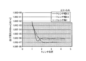
- FIG. 10A is a diagram showing the relationship of the bending loss to the trench position.
- FIG. 10B is a diagram illustrating the relationship of the limit fiber to the trench position.
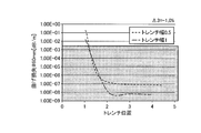
- FIG. 10C is a diagram showing the relationship of the bending loss with respect to the trench position.
- FIG. 10D is a diagram showing the relationship of the limit fiber to the trench position.
- FIG. 11A is a diagram showing the relationship of the bending loss with respect to the trench position.
- FIG. 11B is a diagram illustrating the relationship of the limit fiber to the trench position.
- FIG. 11C is a diagram illustrating the relationship of the bending loss with respect to the trench position.
- FIG. 11D is a diagram showing the relationship of the limit fiber to the trench position.
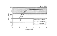
- FIG. 12A is a diagram illustrating a relationship of MFD with respect to a trench position.
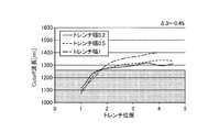
- FIG. 12B is a diagram illustrating the relationship of the cutoff wavelength with respect to the trench position.
- FIG. 12C is a diagram illustrating the relationship of the MFD with respect to the trench position.
- FIG. 12D is a diagram illustrating a relationship of a cutoff wavelength with respect to a trench position.
- FIG. 13A is a diagram illustrating a relationship of MFD with respect to a trench position.
- FIG. 13B is a diagram illustrating the relationship of the cutoff wavelength with respect to the trench position.
- FIG. 13C is a diagram illustrating a relationship of MFD with respect to the trench position.
- FIG. 13D is a diagram illustrating a relationship of a cutoff wavelength with respect to a trench position.
- FIG. 14 is a diagram illustrating the relationship of the MFD with respect to the trench position.
- FIG. 15 is a diagram showing changes in the critical fiber diameter when the parameters are changed.
- the cutoff wavelength is ITU-T G. This is the cable cutoff wavelength defined in 650.1. Other terms not specifically defined in this specification are described in G.C. It shall follow the definition and measurement method in 650.1.
- FIG. 1 is a schematic cross-sectional view of an optical fiber according to the first embodiment.
- the optical fiber 10 includes a core portion 11 located substantially at the center of the optical fiber 10 and a clad portion 12 located on the outer periphery of the core portion 11.
- the clad portion 12 includes an adjacent region 12a surrounding the core portion 11 so as to be adjacent to the outer periphery of the core portion 11, and a non-adjacent region 12b positioned so as to be adjacent to the outer periphery of the adjacent region 12a. . That is, the adjacent region 12a is interposed between the core portion 11 and the non-adjacent region 12b.
- Both the core part 11 and the clad part 12 are made of quartz glass.
- the core portion 11 is made of quartz glass to which a dopant for increasing the refractive index such as germanium (Ge) is added.
- the clad part 12 has a refractive index lower than that of the core part 11.
- the cladding portion 12 is made of pure silica glass in which both the adjacent region 12 a and the non-adjacent region 12 b do not contain a refractive index adjusting dopant such as Ge or fluorine (F).
- the optical fiber 10 is used with a coating made of resin, for example, so as to cover the outer periphery of the cladding portion 12.
- the coating is made of, for example, a UV curable resin and has a layer structure of one layer or two or more layers.
- the UV curable resin include urethane acrylate, polybutadiene acrylate, epoxy acrylate, silicone acrylate, and polyester acrylate.
- the UV curable resin is not particularly limited as long as it is used for optical fiber coating.
- the outer diameter of the cladding portion 12 is set as the fiber diameter to be reduced.
- FIG. 2A and 2B are diagrams showing refractive index profiles in the radial direction from the central axis of the optical fiber 10, respectively.
- profile P11 shows the refractive index profile of the core part 11
- profile P12 shows the refractive index profile of the clad part 12.
- the refractive index profile is indicated by a relative refractive index difference with respect to the cladding portion 12.
- the optical fiber 10 has a step-type refractive index profile
- the core portion 11 has a diameter (core diameter) of 2a
- the relative refractive index difference of the core portion 11 with respect to the cladding portion 12 is ⁇ 1. is there.
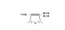
- the refractive index profile of the core portion 11 is not only a step shape having a geometrically ideal shape, but the top shape is not flat, and irregularities are formed due to manufacturing characteristics.
- the shape is such that the hem is pulled from the top.
- at least a part of the value of the top of the refractive index profile within the range of the core diameter 2a in production design is an index for determining ⁇ 1.
- the optical characteristic that is limited when the diameter is reduced is leakage loss due to light leakage.
- the structure of the core portion 11 is the dominant structure with respect to the leakage loss and other characteristics. Therefore, the minimum fiber diameter (limit fiber diameter) necessary to obtain a leakage loss of 0.001 dB / km or less at a wavelength of 1625 nm is simulated by changing the relative refractive index difference ⁇ 1 of the core portion 11 and the core diameter 2a. It was examined by calculation.
- FIG. 3 is a diagram showing the relationship of ⁇ 1 and the limit fiber diameter with respect to the core diameter.
- FIG. 3 there is a condition that leakage loss can be sufficiently suppressed even if the fiber diameter is less than 100 ⁇ m, which is the limit fiber diameter, by optimizing the core part 11 parameter ⁇ 1 and the core diameter. Recognize. As a result, G.
- the optical fiber 10 having a small diameter of less than 100 ⁇ m that satisfies the 652 standard and suppresses leakage loss can be realized. If the fiber diameter is less than 100 ⁇ m, it is much smaller than 125 ⁇ m, which is the fiber diameter in a standard optical fiber.
- the structure (physical properties and thickness) of the coating is not particularly limited. For example, it is preferable to use a coating that is appropriately set to suppress microbending loss, as is well known.
- the top of the refractive index profile of the core portion 11 of the optical fiber 10 is not necessarily flat, but the relative refractive index difference of the top region that determines at least a part of the top, that is, ⁇ 1, is 0.
- the relative refractive index difference in the region of 50% or more of the top is 0.32% to 0.40%.
- the average value, maximum value, and minimum value of the relative refractive index difference at the top within the range of the core diameter 2a in the production design are 0.32% to 0.40% in order to obtain desired characteristics. More preferred.
- the fiber diameter is 90 ⁇ m or less with a margin of about 10% from 100 ⁇ m. From the result of FIG. 2, ⁇ 1 of the core part 11 is 0.335% to 0.375% and the core diameter is 8.2 ⁇ m to 9.2 ⁇ m, or ⁇ 1 is 0.37% to 0.395%.
- the core diameter is preferably 7.6 ⁇ m to 8.3 ⁇ m.
- the optical fiber according to the second embodiment includes a core portion made of silica glass and a clad portion made of silica glass. And non-adjacent regions. Moreover, the coating is formed so that the outer periphery of a clad part may be covered.
- FIG. 4 is a diagram showing a refractive index profile in the radial direction from the central axis of the optical fiber according to the second embodiment.
- a profile P21 indicates the refractive index profile of the core portion
- a profile P22 indicates the refractive index profile of the cladding portion.
- the refractive index profile is indicated by a relative refractive index difference ⁇ .
- the clad portion includes three layers having profiles P22a, P22b, and P22c, respectively.
- the profile P22a is a refractive index profile of an adjacent region, and the adjacent region is made of pure quartz glass.
- the profile P22b is a region to which a dopant that lowers the refractive index such as F is added in the non-adjacent region, and is a refractive index profile of a layered region that concentrically surrounds the core portion. This region is a trench layer.
- the profile P22c is a refractive index profile of a region that is located on the outer periphery of the trench layer in the non-adjacent region and whose outer diameter determines the fiber diameter. This region is made of pure quartz glass and is a reference refractive index region.
- the optical fiber according to the second embodiment has a trench type refractive index profile, the core diameter of the core portion is 2a, and the relative refractive index difference of the core portion with respect to the adjacent region is ⁇ 1.
- the relative refractive index difference between adjacent regions with respect to the reference refractive index region is ⁇ 2, which is 0% in the present embodiment.
- the relative refractive index difference of the trench layer with respect to the reference refractive index region is ⁇ 3.
- the outer diameter of the adjacent region that is, the inner diameter of the trench layer is 2b
- the outer diameter of the trench layer is 2c.
- the optical fiber according to the second embodiment has a structure in which a trench layer is provided in the optical fiber 10 according to the first embodiment, and preferable ranges of ⁇ 1 and the core diameter are the same as those of the optical fiber 10.
- the optical fiber according to the second embodiment is a small-diameter optical fiber in which the leakage loss is suppressed similarly to the optical fiber 10, and the macrobend loss (bending loss) can be reduced by the effect of the trench layer.
- the G.G. G.652 standard or lower macrobend loss is required.
- the relative refractive index difference ⁇ 3 of the trench layer and the inner diameter 2b and the outer diameter 2c of the trench layer there are preferable ranges for the relative refractive index difference ⁇ 3 of the trench layer and the inner diameter 2b and the outer diameter 2c of the trench layer.
- b / a is preferably 2 or more, and b / a is more preferably 3 or more.
- the width (cb) of the trench layer is preferably 0.2 to 1 times a, and ⁇ 3 is preferably ⁇ 0.4% or less.
- FIG. 5 is a diagram showing simulation calculation results of the relationship between wavelength dispersion and MFD with respect to the distance between the trench layer and the core portion in the optical fiber having the trench layer as in the second embodiment.
- the distance between the trench layer and the core portion is a distance (ba) between the outer periphery of the core portion and the inner periphery of the trench layer, and is a value corresponding to the thickness of the adjacent region.
- the core diameter 2a was 10 ⁇ m
- ⁇ 3 was ⁇ 1%
- the width (cb) of the trench layer was 10 ⁇ m, the same as the core diameter 2a.
- the distance between the trench layer and the core portion in FIG. 5 is 0 ⁇ m, indicating that the trench layer is adjacent to the core portion (that is, the trench layer exists in the adjacent region). “No trench” is the case of the optical fiber 10 according to the first embodiment.
- the wavelength dispersion and the MFD change greatly from the case without the trench. It can be seen that when the distance between the core portion and the core portion is about 10 ⁇ m or more, that is, b / a is about 3 or more, the chromatic dispersion and MFD are hardly changed. Further, it can be said that the change in chromatic dispersion and MFD becomes moderate from the distance between the trench layer and the core portion of about 5 ⁇ m, that is, when b / a is 2.
- b / a is It is preferably 2 or more, more preferably b / a is 3 or more.
- FIG. 6 is a diagram showing a result of simulation calculation of the relationship between the amount of change in MFD (solid line) and the amount of change in cutoff wavelength (broken line) with respect to ⁇ 3 when the core portion and the trench layer are adjacent to each other.
- the core diameter and ⁇ 1 are the same as in FIG.
- the width (cb) of the trench layer is 4a.
- the optical fibers according to the first and second embodiments and the modifications thereof are described in G. It can be configured to meet the 652 standard.
- G. ITU-T G.65 which requires characteristics close to the 652 standard.
- 654 standard a so-called cut-off shift fiber, for example, the cut-off wavelength is defined as 1530 nm or less
- G. When designing an optical fiber satisfying the 657 standard (so-called bending resistant fiber), it is preferable to employ the refractive index profile of the core portion of the optical fiber according to the first and second embodiments and the modifications thereof.
- optical fibers according to the first and second embodiments and the modifications thereof have a small diameter, the amount of the glass material constituting the clad portion is small, so that the raw material cost is reduced.
- the optical fiber according to the present invention is a small-diameter optical fiber in which leakage loss is suppressed. It is practically preferable to satisfy the 652 standard. That is, a leakage loss of 0.001 dB / km or less is realized at a wavelength of 1625 nm. 652A, G.A. 652B, G.G. 652C, G.G. It is preferable to satisfy the 652D standard. For macro bend loss, see G. In the 652A standard, it is a value at a wavelength of 1550 nm. 652B, G.G. 652C, G.G. In the 652D standard, the value is at a wavelength of 1625 nm. In the following tables, “E” represents a power of 10, for example, “5.3E-3” means “5.3 ⁇ 10 ⁇ 3 ”.
- Table 2 shows an example of the result of simulation calculation of the characteristics of the optical fiber 10 according to Embodiment 1 with ⁇ 1 set to 0.32% to 0.40% and the core diameter 2a set to 7 ⁇ m to 10 ⁇ m.
- G The 652A standard is satisfied, and the critical fiber diameter is less than 100 ⁇ m.
- the fiber diameter can be 80 ⁇ m. That is, the optical fibers having these ⁇ 1 and core diameters are optical fibers having a fiber diameter of less than 100 ⁇ m and a small influence of leakage loss in a wavelength band in which a single mode operation is performed with a cutoff wavelength of 1625 nm or less.
- microbend loss In actual optical fibers, factors such as microbend loss are also added. Therefore, a coating structure having optimum resin physical properties and thickness is used so that the microbend loss can be further suppressed after using the parameters shown in Table 2. It is important to use.
- an optical fiber as an example of the present invention was manufactured by a known method.
- ⁇ 1 was 0.37%
- the core diameter was 8.5 ⁇ m
- the fiber diameter was 90 ⁇ m.
- the resin material of the coating G.I. What was used for the normal optical fiber which meets 650.2 standards was used, but the outer diameter of the primary layer was 100 ⁇ m, and the outer diameter of the secondary layer was 125 ⁇ m, which was thinner than usual.
- FIG. 7 is a diagram illustrating a measurement result of the transmission loss of the optical fiber of the example.
- FIG. 7 in the transmission loss spectrum of the optical fiber of the example, an increase in loss on the long wavelength side was not confirmed. This means that leakage loss hardly occurs in the optical fiber of the example.
- Table 3 the calculation example as the simulation result and the actually measured value of the example coincided with each other with good accuracy.
- the optical fiber according to Embodiment 2 can be made smaller in diameter based on simulation results.
- simulation calculation was performed by fixing ⁇ 1 to 3.6% and changing the core diameter 2a, the trench position, the trench width, ⁇ 3, and the like.
- the trench position is b / a.
- the trench width is a value normalized by the core diameter, that is, the trench width is (c ⁇ b) / a.
- the core diameter 2a is set to 9 ⁇ m
- ⁇ 3 is set to ⁇ 0.4%, ⁇ 0.6%, ⁇ 0.7%, and ⁇ 1.0%
- the simulation calculation is performed by changing the trench position and the trench width. went.
- FIG. 8A to FIG. 8D and FIG. 9A to FIG. 9D are diagrams showing the relationship between the dispersion characteristic with respect to the trench position, that is, the zero dispersion wavelength and the dispersion slope.
- the dispersion slope is the value at the zero dispersion wavelength.
- 8A and 8B show the case where ⁇ 3 is ⁇ 0.4%
- FIGS. 8C and 8D show the case where ⁇ 3 is ⁇ 0.6%
- 9A and 9B show the case where ⁇ 3 is ⁇ 0.7%
- FIGS. 9C and 9D show the case where ⁇ 3 is ⁇ 1.0%.
- FIG. 10A to FIG. 10D and FIG. 11A to FIG. 11D are diagrams showing the relationship between the optical confinement characteristic with respect to the trench position, that is, the bending loss (macrobending loss) and the critical fiber diameter.
- the bending loss is a value at a wavelength of 1550 nm when bent at a diameter of 60 mm.
- 10A and 10B show the case where ⁇ 3 is ⁇ 0.4%
- FIGS. 10C and 10D show the case where ⁇ 3 is ⁇ 0.6%
- 11A and 11B show the case where ⁇ 3 is ⁇ 0.7%
- FIGS. 11C and 11D show the case where ⁇ 3 is ⁇ 1.0%.
- 12 and 13 are diagrams showing the relationship between the MFD and the cutoff wavelength with respect to the trench position.
- MFD is a value at a wavelength of 1310 nm.
- 12A and 12B show the case where ⁇ 3 is ⁇ 0.4%
- FIGS. 12C and 12D show the case where ⁇ 3 is ⁇ 0.6%.
- 13A and 13B show the case where ⁇ 3 is ⁇ 0.7%
- FIGS. 13C and 13D show the case where ⁇ 3 is ⁇ 1.0%.
- the range surrounded by the thick line indicates the target value for the limit fiber diameter in FIGS. 10B, 10D, 11B, and 11D, and G.
- the range of the 652A standard is shown.
- the target value is set to 80 ⁇ m or less here, it may be a small diameter of less than 100 ⁇ m.
- the MFD becomes larger as the trench position becomes larger and satisfies the standard, and then becomes a stable value.
- the cut-off wavelength has a trade-off relationship with MFD, and becomes larger as the trench position becomes larger and does not satisfy the standard. Therefore, it is preferable to set the trench position so that both the MFD and the cutoff wavelength satisfy the standard.
- Table 4 shows the case where ⁇ 3 is ⁇ 0.4%.
- Table 5 shows the case where ⁇ 3 is ⁇ 0.6%.
- G. The symbol “ ⁇ ” was shown when the 652A standard was satisfied, and the symbol “X” was shown otherwise.
- G.I. There are many combinations of parameters that satisfy the 652A standard and have a critical fiber diameter of less than 100 ⁇ m. In particular, when ⁇ 3 is ⁇ 0.6%, there is a combination in which the critical fiber diameter is 80 ⁇ m or less. For example, when the trench width was 1.0 and the trench position was 3.0, the critical fiber diameter was 78 ⁇ m.
- (cb) / a is 0.2 to 1, that is, (cb) is 0.2 to 1 times a.
- ⁇ 2 is preferably ⁇ 0.4% or less.
- FIG. 14 and Table 6 show the relationship of MFD to trench position. As compared with the MFD without the trench, it was found that the MFD is small when the trench position is small, and the MFD increases as the trench position becomes large, but it does not become larger than the MFD without the trench.
- the bending loss (macro bend loss) can be reduced by the effect of the trench layer, a lower macro bend loss is required. It is suitable for application to optical fibers that meet the 657 standard. Also, by allowing the cutoff wavelength to shift to a longer wavelength, It is suitable for application to an optical fiber that satisfies the 654 standard.
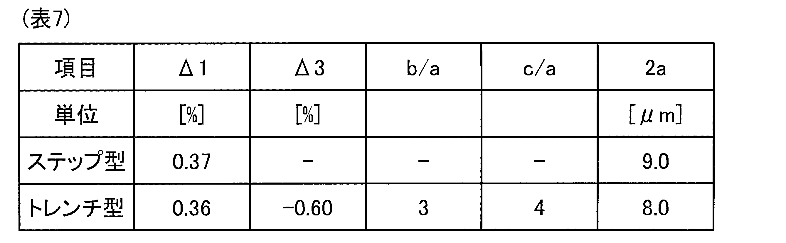
- Table 7 shows combinations of parameters.
- Table 8 shows G.G. The optical characteristics of the optical fiber in the case of 652A standard and Table 7 are shown.
- a critical fiber diameter of 80 ⁇ m was obtained by optimizing the refractive index profile of the core.
- a limit fiber diameter of 78 ⁇ m was obtained due to the effect of the trench layer.
- G Optical characteristics of the optical fiber in the case of 657A2 standard and Table 7 are shown.
- the macrobend loss is defined as a value at a wavelength of 1550 nm when bent at a diameter of 20 mm.
- the standard is more stringent than 652.
- G. The 657A2 standard could be satisfied, and the trench type superiority was confirmed.
- Table 10 shows the parameter combinations of trenches 2 to 15 in which ⁇ 1, ⁇ 3, b / a, c / a, and 2a are changed using the optimum trench type parameters shown in Table 5 as a reference value (trench 1).
- the symbol “-” indicates the same value as the reference value.
- Table 11 shows G. The optical characteristics of the optical fiber using the 652A standard and the parameters of the trenches 1 to 15 are shown.
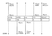
- FIG. 15 is a diagram showing changes in the critical fiber diameter when the parameters are changed.
- the parameters are changed in the direction of change such as trenches 3, 5, 8, 11, and 14 (increase (UP) or decrease (DOWN) indicated by solid arrows in FIG. 15).
- the limit fiber diameter can be further reduced from 78 ⁇ m by changing in the direction), but the cutoff wavelength is also shifted to the long wavelength side.
- the trenches 3, 5, 8, 11, and 14 have characteristics when the cutoff wavelength is around 1260 nm, which is the upper limit of the standard. However, since the cutoff wavelength of the reference trench 1 is 1252 nm, which is close to the upper limit of the standard, it is improved.
- the refractive index profile of the optical fiber is a step type and a trench type, but these are examples of a preferable embodiment. That is, the present invention is not limited to these, and includes cases where the effects of the present invention are obtained using parameters different from those described above, for example, step type and trench type. In addition to the step type and the trench type, the present invention also includes a case where the core portion having the above-described optimum structure is employed to realize a small-diameter optical fiber having highly versatile characteristics.
- an optical fiber having a so-called W-type refractive index profile in which a trench layer is adjacent to the core portion in the trench type is also included in the present invention.
- a ⁇ + layer may be provided at a suitable position with respect to the core portion having the optimum structure.
- the ⁇ + layer is a layer that surrounds the core portion and has a positive relative refractive index difference with respect to the reference refractive index region in the cladding portion.
- optical fiber according to the present invention can be suitably used for signal transmission.
Landscapes
- Physics & Mathematics (AREA)
- General Physics & Mathematics (AREA)
- Optics & Photonics (AREA)
- Optical Fibers, Optical Fiber Cores, And Optical Fiber Bundles (AREA)
Abstract
リーケージ損失が抑制された細径の光ファイバを提供することを目的として、光ファイバは、ガラスからなるコア部と、コア部の外周に位置し、コア部の屈折率よりも低い屈折率を有するガラスからなるクラッド部と、を備え、クラッド部の外径は100μm未満であり、クラッド部に対するコア部の比屈折率差が0.32%~0.40%である。光ファイバは、コア部のコア径が7μm~10μmであってもよい。光ファイバは、コア部の比屈折率差が0.335%~0.375%であってもよく、コア部のコア径が8.2μm~9.2μmであってもよい。
Description
本発明は、光ファイバに関する。
データコムやテレコムの分野において、高密度光ファイバケーブルを実現する光ファイバとして、細径の光ファイバが注目されている。従来、細径の光ファイバとして、クラッド部に対するコア部の比屈折率差を高くした構成が開示されている(非特許文献1)。また、コア部に隣接してトレンチ層を設けた構成が開示されている(特許文献1)。
村瀬 他、「細径クラッドファイバの開発」、昭和電線レビュー、vol.53、N0.1(2003)、pp.32-36
しかしながら、非特許文献1に開示される光ファイバは、その特性が、たとえばITU-T(国際電気通信連合)G.650.2で定義される標準的なシングルモード光ファイバの規格(以下、G.650.2規格)を満たすものではない。また、特許文献1に開示される光ファイバは、その特性がG.650.2規格を満たすものの、そのクラッド部の外径(ファイバ径)は100μm~125μm程度であり、今後益々要求が高まる細径化の点では不十分である。また、光ファイバの細径化を行うとリーケージ損失が増大するが、リーケージ損失が十分な低さに抑制され、かつ細径化された光ファイバは開示されていなかった。
本発明は、上記に鑑みてなされたものであって、その目的は、リーケージ損失が抑制された細径の光ファイバを提供することにある。
上述した課題を解決し、目的を達成するために、本発明の一態様に係る光ファイバは、ガラスからなるコア部と、前記コア部の外周に位置し、前記コア部の屈折率よりも低い屈折率を有するガラスからなるクラッド部と、を備え、前記クラッド部の外径は100μm未満であり、前記クラッド部に対する前記コア部の比屈折率差が0.32%~0.40%であることを特徴とする。
本発明の一態様に係る光ファイバは、前記コア部のコア径が7μm~10μmであることを特徴とする。
本発明の一態様に係る光ファイバは、前記コア部の比屈折率差が0.335%~0.375%であり、前記コア部のコア径が8.2μm~9.2μmであることを特徴とする。
本発明の一態様に係る光ファイバは、前記コア部の比屈折率差が0.37%~0.395%であり、前記コア部のコア径が7.6μm~8.3μmであることを特徴とする。
本発明の一態様に係る光ファイバは、前記クラッド部は、前記コア部の外周に隣接する隣接領域と、前記隣接領域の外周に位置し、前記コア部との間に前記隣接領域が介在する非隣接領域とを備え、前記隣接領域は、純石英ガラスからなることを特徴とする。
本発明の一態様に係る光ファイバは、前記非隣接領域は、純石英ガラスからなることを特徴とする。
本発明の一態様に係る光ファイバは、前記非隣接領域は、前記隣接領域の屈折率よりも低い屈折率を有するトレンチ層を有することを特徴とする。
本発明の一態様に係る光ファイバは、前記コア部のコア径を2a、前記トレンチ層の内径を2bとしたときに、b/aが2以上であることを特徴とする。
本発明の一態様に係る光ファイバは、前記コア部のコア径を2a、前記トレンチ層の内径を2bとしたときに、b/aが3以上であることを特徴とする。
本発明の一態様に係る光ファイバは、前記コア部のコア径を2a、前記トレンチ層の内径を2b、外径を2cとしたときに、前記トレンチ層の幅(c-b)がaの0.2倍~1倍であることを特徴とする。
本発明の一態様に係る光ファイバは、前記トレンチ層の前記隣接領域に対する比屈折率差が-0.4%以下であることを特徴とする。
本発明の一態様に係る光ファイバは、前記クラッド部は、前記コア部に隣接するトレンチ層を有し、前記トレンチ層の前記トレンチ層以外の前記クラッド部に対する比屈折率差が-0.1%以上0%未満であることを特徴とする。
本発明の一態様に係る光ファイバは、波長1310nmにおけるモードフィールド径が8.6μm~9.5μmであることを特徴とする。
本発明の一態様に係る光ファイバは、直径60mmで曲げた場合の波長1550nmにおける曲げ損失が5.3×10⁻³dB/m以下であることを特徴とする。
本発明の一態様に係る光ファイバは、ゼロ分散波長が1300nm~1324nmであり、前記ゼロ分散波長での分散スロープが0.092ps/nm2/km以下であることを特徴とする。
本発明の一態様に係る光ファイバは、ケーブルカットオフ波長が1260nm以下であることを特徴とする。
本発明の一態様に係る光ファイバは、波長1550nmにおけるモードフィールド径が9.5μm以上であることを特徴とする。
本発明の一態様に係る光ファイバは、ケーブルカットオフ波長が1530nm以下であることを特徴とする。
本発明によれは、リーケージ損失が抑制された細径の光ファイバを実現できるという効果を奏する。
以下に、図面を参照しながら、本発明の実施形態を詳細に説明する。なお、以下に説明する実施形態により本発明が限定されるものではない。また、各図面において、同一又は対応する構成要素には適宜同一の符号を付している。また、本明細書においては、カットオフ波長(Cutoff波長)とは、ITU-T G.650.1で定義するケーブルカットオフ波長をいう。また、その他、本明細書で特に定義しない用語についてはG.650.1における定義、測定方法に従うものとする。
(実施形態1)
図1は、実施形態1に係る光ファイバの模式的断面図である。光ファイバ10は、光ファイバ10の略中心に位置するコア部11と、コア部11の外周に位置するクラッド部12とを備えている。クラッド部12は、コア部11の外周に隣接するように取り囲む隣接領域12aと、隣接領域12aの外周に位置し、隣接領域12aの外周に隣接するように取り囲む非隣接領域12bとを備えている。すなわち、コア部11と非隣接領域12bとの間に隣接領域12aが介在する。
図1は、実施形態1に係る光ファイバの模式的断面図である。光ファイバ10は、光ファイバ10の略中心に位置するコア部11と、コア部11の外周に位置するクラッド部12とを備えている。クラッド部12は、コア部11の外周に隣接するように取り囲む隣接領域12aと、隣接領域12aの外周に位置し、隣接領域12aの外周に隣接するように取り囲む非隣接領域12bとを備えている。すなわち、コア部11と非隣接領域12bとの間に隣接領域12aが介在する。
コア部11とクラッド部12とは、いずれも石英系ガラスからなる。たとえば、コア部11は、ゲルマニウム(Ge)などの屈折率を高めるドーパントが添加された石英ガラスからなる。クラッド部12は、コア部11の屈折率よりも低い屈折率を有する。また、光ファイバ10では、クラッド部12は、隣接領域12a及び非隣接領域12bのいずれもが、Ge、フッ素(F)などの屈折率調整用のドーパントを含まない純石英ガラスからなる。
なお、光ファイバ10は、クラッド部12の外周を覆うように、たとえば樹脂からなるコーティングが形成されて使用される。コーティングは、たとえばUV硬化樹脂等からなり、1層又は2層以上の層構造を有する。UV硬化樹脂としては、たとえばウレタンアクリレート系、ポリブタジエンアクリレート系、エポキシアクリレート系、シリコーンアクリレート系、ポリエステルアクリレート系などがあるが、光ファイバのコーティングに使用されるものであれば特に限定されない。また、光ファイバ10では、ガラス部分であるコア部11とクラッド部12との細径化に着目するので、クラッド部12の外径を細径化の対象であるファイバ径とする。
図2A及び図2Bはそれぞれ、光ファイバ10の中心軸から半径方向における屈折率プロファイルを示す図である。図2Aにおいて、プロファイルP11がコア部11の屈折率プロファイルを示し、プロファイルP12がクラッド部12の屈折率プロファイルを示す。なお、屈折率プロファイルは、クラッド部12に対する比屈折率差で示している。図2Aに示すように、光ファイバ10はステップ型の屈折率プロファイルを有し、コア部11の直径(コア径)は2aであり、クラッド部12に対するコア部11の比屈折率差はΔ1である。
なお、図2Bに示すように、コア部11の屈折率プロファイルは、幾何学的に理想的な形状のステップ型である場合だけでなく、頂部の形状が平坦ではなく製造特性により凹凸が形成されたり、頂部から裾を引くような形状となっていたりする場合がある。この場合、製造設計上のコア径2aの範囲内における、屈折率プロファイルの頂部の少なくとも一部の値が、Δ1を決定する指標となる。
つづいて、光ファイバ10の細径化のための設計について説明する。光ファイバ10において、細径化していくときに制限となる光学特性は、光漏れによるリーケージ損失である。このリーケージ損失や他の特性に対して、支配的な構造となるのがコア部11の構造である。そこで、コア部11の比屈折率差Δ1やコア径2aを変化させて、波長1625nmにおいて0.001dB/km以下のリーケージ損失を得るのに必要な最低限のファイバ径(限界ファイバ径)をシミュレーション計算によって検討した。
本検討では、G.652規格による以下の(1)~(5)の規格、すなわち(1)波長1310nmにおけるモードフィールド径(MFD)が8.6μm~9.5μm、(2)直径60mmで曲げた場合の波長1550nmにおける曲げ損失が5.3×10⁻³dB/m以下、(3)ゼロ分散波長が1300nm~1324nm、(4)ゼロ分散波長での分散スロープが0.092ps/nm2/km以下(5)ケーブルカットオフ波長が1260nm以下、を満たすものを調べた。
図3は、Δ1、コア径に対する限界ファイバ径の関係を示す図である。図3に示すように、コア部11のパラメータであるΔ1、コア径を最適化する事で、ファイバ径を限界ファイバ径である100μm未満にしてもリーケージ損失が十分に抑制できる条件があることがわかる。これにより、G.652規格を満たすと共に、従来の光ファイバと比べてファイバ径が100μ未満の細径化を実現する事が可能となる。具体的には、Δ1を0.32%~0.40%、コア径を7μm~10μmにすることで、G.652規格を満たし、リーケージ損失が抑制された、ファイバ径が100μm未満の細径の光ファイバ10を実現できる。ファイバ径が100μm未満であれば、標準的な光ファイバにおけるファイバ径である125μmよりも大幅に小さいものとなる。なお、コーティングの構造(物性や厚み)などは、特に限定されないが、たとえば、公知のように、マイクロベンド損失などを抑制するために適切に設定されたものを使用することが好ましい。
また、上述したように、光ファイバ10のコア部11の屈折率プロファイルの頂部は必ずしも平坦な形状ではないが、頂部の少なくとも一部、すなわちΔ1を決定する頂部の領域の比屈折率差が0.32%~0.40%であることで、リーケージ損失及び細径の特性が得られる。より好ましくは、頂部の50%以上の領域の比屈折率差が0.32%~0.40%であることが好ましい。さらに、製造設計上のコア径2aの範囲内における頂部の比屈折率差の平均値や最大値及び最小値が0.32%~0.40%であることが、所望の特性を得る点でより好ましい。
さらに、光ファイバ10を実際にケーブル化することを考慮すると、リーケージ損失に加えて、コーティングの影響やマイクロベンド損失などの影響も生じる。そのため、ファイバ径として、100μmよりも1割程度余裕がある90μm以下を実現できる設計とすることが好ましい。図2の結果から、コア部11のΔ1が0.335%~0.375%でありコア径が8.2μm~9.2μmである、又は、Δ1が0.37%~0.395%でありコア径が7.6μm~8.3μmであることが好ましい。
(実施形態2)
実施形態2に係る光ファイバは、実施形態1に係る光ファイバ10と同様に、石英系ガラスからなるコア部と、石英系ガラスからなるクラッド部とを備えており、クラッド部は、隣接領域と非隣接領域とを備えている。また、クラッド部の外周を覆うようにコーティングが形成されている。
実施形態2に係る光ファイバは、実施形態1に係る光ファイバ10と同様に、石英系ガラスからなるコア部と、石英系ガラスからなるクラッド部とを備えており、クラッド部は、隣接領域と非隣接領域とを備えている。また、クラッド部の外周を覆うようにコーティングが形成されている。
図4は、実施形態2に係る光ファイバの中心軸から半径方向における屈折率プロファイルを示す図である。図4において、プロファイルP21がコア部の屈折率プロファイルを示し、プロファイルP22がクラッド部の屈折率プロファイルを示す。なお、屈折率プロファイルは、比屈折率差Δで示している。
プロファイルP22が示すように、クラッド部は、それぞれプロファイルP22a、P22b、P22cを有する3つの層を備える。プロファイルP22aは、隣接領域の屈折率プロファイルであり、隣接領域は純石英ガラスからなる。プロファイルP22bは、非隣領域内において、Fなどの屈折率を低くするドーパントが添加された領域であり、コア部を同心円状に囲む層状の領域の屈折率プロファイルである。この領域をトレンチ層とする。プロファイルP22cは、非隣領域内においてトレンチ層の外周に位置し、その外径がファイバ径を確定する領域の屈折率プロファイルである。この領域は、純石英ガラスからなり、基準屈折率領域である。
図4に示すように、実施形態2に係る光ファイバはトレンチ型の屈折率プロファイルを有し、コア部のコア径は2aであり、隣接領域に対するコア部の比屈折率差はΔ1である。基準屈折率領域に対する隣接領域の比屈折率差はΔ2であり、本実施形態では0%である。基準屈折率領域に対するトレンチ層の比屈折率差はΔ3である。また、隣接領域の外径すなわちトレンチ層の内径はいずれも2bであり、トレンチ層の外径は2cである。
実施形態2に係る光ファイバは、実施形態1に係る光ファイバ10にトレンチ層を設けた構造であり、Δ1及びコア径の値の好ましい範囲は光ファイバ10と同じである。これにより、実施形態2に係る光ファイバは、光ファイバ10と同様にリーケージ損失が抑制された細径の光ファイバであり、かつトレンチ層の効果によってマクロベンド損失(曲げ損失)を低減できる。
ただし、実施形態2に係る光ファイバにおいて、光ファイバ10と同様にG.652規格を満たす、あるいはより低いマクロベンド損失が求められるG.657規格を満たすようにするには、トレンチ層の比屈折率差Δ3や、トレンチ層の内径2b、外径2cには好ましい範囲がある。たとえば、コア径2aに対して、b/aが2以上であることが好ましく、b/aが3以上であることがより好ましい。また、トレンチ層の幅(c-b)がaの0.2倍~1倍であることが好ましく、Δ3が-0.4%以下であることが好ましい。これらについては後述する。
図5は、実施形態2のようにトレンチ層を有する光ファイバにおいて、トレンチ層とコア部との距離に対する波長分散、MFDの関係をシミュレーション計算した結果した示す図である。ここで、トレンチ層とコア部との距離とは、コア部の外周とトレンチ層の内周との距離(b-a)であり、隣接領域の厚さに対応する値である。なお、コア径2aは10μmとし、Δ3は-1%とし、トレンチ層の幅(c-b)はコア径2aと同じ10μmとした。なお、図5中でトレンチ層とコア部との距離が0μmとは、トレンチ層がコア部に隣接している(すなわち、隣接領域にトレンチ層が存在する)場合を示している。また、「トレンチ無し」とは、実施形態1に係る光ファイバ10の場合である。
図5に示すように、トレンチ層とコア部との距離が0μm(すなわちコア部とトレンチ層とが隣接)の場合は、トレンチ無しの場合からの波長分散、MFDの変化が大きいが、トレンチ層とコア部との距離が10μm程度以上、すなわちb/aが3程度以上になると波長分散、MFDの変化がほとんど無い安定した状態となることがわかる。また、トレンチ層とコア部との距離が5μm程度から、すなわちb/aが2の場合から、波長分散、MFDの変化が緩やかになるといえる。したがって、トレンチ層を設けたことによる光ファイバ10からの特性変化を抑制するためには、Δ3が-1%程度と大きい場合は、トレンチ層を非隣接領域に設けることが好ましく、b/aが2以上であることが好ましく、b/aが3以上であることがさらに好ましい。
ただし、本発明はこれに限らず、実施形態2の変形例として、コア部とトレンチ層とを隣接させてもよい。図6は、コア部とトレンチ層が隣接する場合の、Δ3に対するMFD変化量(実線)、カットオフ波長変化量(破線)の関係をシミュレーション計算した結果した示す図である。コア径とΔ1は図5の場合と同じである。また、トレンチ層の幅(c-b)は4aとしている。なお、これらの変化量は、コア径をカットオフ波長が1160nm~1260nmになるように3点ほど振って算出したものである。図6から、トレンチ層の幅(c-b)を4aと比較的広くしても、Δ3を-0.1%程度以上0%未満にした場合には、MFDやカットオフ波長の変化量が十分に小さいことがわかる。なお、トレンチ層の幅(c-b)を4aよりも狭くすると変化量をより小さくできるが、この場合は許容されるMFDやカットオフ波長などの変化量に応じて、-0.1%以上0%未満の範囲内でΔ3を設定することが好ましい。
以上の実施形態1、2及びその変形例に係る光ファイバは、G.652規格を満たすように構成することができる。また、G.652規格に近い特性が要求されるITU-T G.654規格(いわゆるカットオフシフトファイバであり、たとえばカットオフ波長が1530nm以下と規定される)やG.657規格(いわゆる曲げ耐性ファイバ)を満たす光ファイバを設計する場合には、実施形態1、2及びその変形例に係る光ファイバのコア部の屈折率プロファイルを採用することが好適である。
さらに、実施形態1、2及びその変形例に係る光ファイバは、細径のためクラッド部を構成するガラス材料の量が少ないので、原料コストが低減された光ファイバである。
以下、本発明についてさらに説明する。本発明に係る光ファイバは、リーケージ損失が抑制された細径の光ファイバであるが、上記のようにG.652規格を満たすものであることが、実用上好ましい。すなわち、波長1625nmにおいて0.001dB/km以下のリーケージ損失を実現し、さらに、表1に示すG.652A、G.652B、G.652C、G.652Dの規格を満たすことが好ましい。なお、マクロベンド損失については、G.652A規格では波長1550nmにおける値であるが、G.652B、G.652C、G.652Dの規格では波長1625nmにおける値である。なお、以降の表において、「E」は10のべき乗を表し、たとえば「5.3E-3」は「5.3×10-3」を意味している。

表2は、実施形態1に係る光ファイバ10において、Δ1を0.32%~0.40%、コア径2aを7μm~10μmに設定してその特性をシミュレーション計算した結果の一例を示す。いずれの場合も、G.652A規格を満たし、かつ限界ファイバ径が100μm未満である。特に、Δ1が0.37%、2aが9.0μmの場合は、ファイバ径を80μmとすることができることがわかる。すなわち、これらのΔ1、コア径を有する光ファイバは、ファイバ径が100μm未満であり、カットオフ波長以上1625nm以下のシングルモード動作する波長帯で、リーケージ損失の影響が小さい光ファイバである。

なお、実際の光ファイバでは、マイクロベンド損失などの要因も加わるため、表2に示すパラメータを用いた上で、さらにマイクロベンド損失を抑制できるように、最適な樹脂物性や厚みを有するコーティング構造を用いることが重要である。
ここで、表2のシミュレーション結果と実際の光ファイバの特性との整合性を調査するために、周知の方法によって本発明の実施例としての光ファイバを製造した。実施例の光ファイバにおいて、Δ1は0.37%とし、コア径は8.5μmとし、ファイバ径を90μmとした。なお、コーティングの樹脂材料については、G.650.2規格を満たす通常の光ファイバに用いられているものを用いたが、プライマリ層の外径を100μmとし、セカンダリ層の外径を125μmと、通常よりも薄肉にした。
図7は、実施例の光ファイバの伝送損失の測定結果を示す図である。図7に示すように、実施例の光ファイバの伝送損失スペクトルにおいて、長波長側における損失の増加は確認されなかった。このことは、実施例の光ファイバにおいて、リーケージ損失がほとんど発生しないことを意味する。また、表3に示すように、シミュレーション結果である計算例と実施例の実測値とはよい精度で一致した。

つづいて、実施形態2に係る光ファイバについて、より細径にできることをシミュレーション結果に基づいて説明する。以下では、Δ1を3.6%に固定し、コア径2a、トレンチ位置、トレンチ幅、Δ3などを変化させてシミュレーション計算を行った。ここで、トレンチ位置とは、b/aのことである。また、トレンチ幅は、コア径で規格化した値とする、すなわち、トレンチ幅は(c-b)/aである。
まず、コア径2aを9μmとし、Δ3を、-0.4%、-0.6%、-0.7%、-1.0%とし、トレンチ位置とトレンチ幅とを変化させてシミュレーション計算を行った。
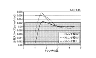
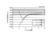
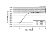
図8A~図8Dおよび図9A~図9Dは、トレンチ位置に対する分散特性、すなわちゼロ分散波長、分散スロープの関係を示す図である。分散スロープはゼロ分散波長における値である。図8A、図8BはΔ3が-0.4%の場合であり、図8C、図8DはΔ3が-0.6%の場合である。また、図9A、図9BはΔ3が-0.7%の場合であり、図9C、図9DはΔ3が-1.0%の場合である。
図10A~図10Dおよび図11A~図11Dは、トレンチ位置に対する光閉じ込め特性、すなわち曲げ損失(マクロベンディング損失)、限界ファイバ径の関係を示す図である。曲げ損失は直径60mmで曲げた場合の波長1550nmにおける値である。図10A、図10BはΔ3が-0.4%の場合であり、図10C、図10DはΔ3が-0.6%の場合である。また、図11A、図11BはΔ3が-0.7%の場合であり、図11C、図11DはΔ3が-1.0%の場合である。
図12及び図13は、トレンチ位置に対するMFD、カットオフ波長の関係を示す図である。MFDは波長1310nmにおける値である。図12A、図12BはΔ3が-0.4%の場合であり、図12C、図12DはΔ3が-0.6%の場合である。また、図13A、図13BはΔ3が-0.7%の場合であり、図13C、図13DはΔ3が-1.0%の場合である。
図8A~図13Dにおいて、太線で囲んだ範囲は、図10B、図10D、図11B、図11Dにおける限界ファイバ径については目標値を示し、その他についてはG.652A規格の範囲を示している。なお、ここでは目標値を80μm以下に設定しているが、100μm未満の細径であればよい。
図8A~図8D及び図9A~図9Dから明らかなように、トレンチ位置が小さい、すなわちトレンチ層がコア部に近いと、分散特性は大きく変化し、トレンチ位置が大きくなるにつれて、分散特性の変化が緩やかになり、規格内に安定して収まる。また、図10A~図10D及び図11A~図11Dから明らかなように、光閉じ込め特性は、分散特性と同様にトレンチ位置が小さいと特性の変化が大きいが、その変化は不規則である。また、トレンチ位置が大きくなるにつれて、光閉じ込め特性の変化が緩やかになり、曲げ損失が規格内に収まり、限界ファイバ径も80μm以下となる。
一方、図12A~図12D及び図13A~図13Dから明らかなように、MFDについてはトレンチ位置が大きくなるにつれて大きくなって規格を満たすようになり、その後安定した値となる。しかし、カットオフ波長については、MFDとトレードオフの関係にあり、トレンチ位置が大きくなると大きくなって規格を満たさないようになる。したがって、MFDとカットオフ波長との両方が規格を満たすようにトレンチ位置を設定することが好ましい。
つづいて、コア径2aを8μmとし、トレンチ位置とトレンチ幅とを変化させてシミュレーション計算を行った。なお、Δ3については、-0.4%、-0.6%とし、-0.7%、-1.0%については、このようにΔ3を小さくしても、規格で定める光学特性にあまり影響がないことが解ったので、光ファイバの製造性を考慮し、以下では計算を省略した。
表4は、Δ3が-0.4%の場合を示している。表5は、Δ3が-0.6%の場合を示している。なお、G.652A規格を満たす場合は記号「〇」を示し、満たさない場合は記号「×」を示した。表4、5に示すように、G.652A規格を満たし、かつ限界ファイバ径が100μm未満となるパラメータの組み合わせが数多く存在した。特に、Δ3が-0.6%の場合、限界ファイバ径が80μm以下となる組み合わせも存在した。たとえば、トレンチ幅が1.0、トレンチ位置が3.0の場合は、限界ファイバ径が78μmであった。
このように、トレンチ位置についてb/aが2倍以上の場合に、(c-b)/aが0.2~1、すなわち、(c-b)がaの0.2倍~1倍であることが好ましい。また、Δ2は、-0.4%以下であることが好ましい。


このように、トレンチ位置についてb/aが2倍以上の場合に、(c-b)/aが0.2~1、すなわち、(c-b)がaの0.2倍~1倍であることが好ましい。また、Δ2は、-0.4%以下であることが好ましい。
つづいて、コア径2aを7μmとし、トレンチ位置とトレンチ幅とを変化させてシミュレーション計算を行った。図14と表6は、トレンチ位置に対するMFDの関係を示す。トレンチ無しの場合のMFDと比較とすると、トレンチ位置が小さい場合はMFDが小さく、トレンチ位置が大きくなるにつれてMFDが大きくなるが、トレンチ無しの場合のMFDより大きくはならないことがわかった。

以上のシミュレーション結果の範囲では、トレンチ層を有する実施形態2に係る光ファイバの場合、コア径2aが8μmの場合が最適であることが確認された。
なお、実施形態2に係る光ファイバの場合、トレンチ層の効果によって曲げ損失(マクロベンド損失)を低減できるので、より低いマクロベンド損失が求められるG.657規格を満たす光ファイバに適用するのに好適である。また、カットオフ波長がより長波長にシフトすることを許容することで、G.654規格を満たす光ファイバに適用するのに好適である。
次に、表2に示すステップ型のパラメータの組み合わせのうち最も良好な特性を示したものと、表5に示すトレンチ型のパラメータの組み合わせのうち最も良好な特性を示したものとを、最適なパラメータの組み合わせとして表7に示す。そして、表8に、G.652A規格と、表7の場合の光ファイバの光学特性を示す。ステップ型については、コア部の屈折率プロファイルの最適化により限界ファイバ径として80μmが得られた。また、トレンチ型についてはトレンチ層の効果により限界ファイバ径として78μmが得られた。

次に、表9に、G.657A2規格と、表7の場合の光ファイバの光学特性を示す。G.657A規格の場合、マクロベンド損失として、直径20mmで曲げた場合の波長1550nmにおける値が規定されており、G.652よりも要求がより厳しい規格となっている。表9からわかるように、トレンチ型の場合にG.657A2規格を満たすことができ、トレンチ型の優位性が確認された。

次に、表5に示すトレンチ型の最適なパラメータを変化させた場合、光ファイバの光学特性がどのように変化するかについて説明する。表10は、表5に示すトレンチ型の最適なパラメータを基準値(トレンチ1)として、Δ1、Δ3、b/a、c/a、2aを変化させたトレンチ2~15のパラメータ組み合わせを示す。なお、表中、記号「-」は基準値と同じ値であることを示す。そして、表11は、G.652A規格と、トレンチ1~15のパラメータとした光ファイバの光学特性を示す。


図15は、パラメータを変化させたときの限界ファイバ径の変化を示す図である。表10、11の結果から明らかなように、たとえばパラメータをトレンチ3、5、8、11、14のような変化の方向(図15の実線の矢印で示す増加(UP)又は減少(DOWN)の方向)に変化させることで、限界ファイバ径を78μmからさらに小さくすることができるが、カットオフ波長も長波長側にシフトしてしまうことがわかる。トレンチ3、5、8、11、14は、カットオフ波長が規格上限の1260nm付近の場合の特性となっているが、基準であるトレンチ1のカットオフ波長が1252nmと規格の上限に近いので改善の余地が少ないことがわかる。また、図15に示すように、限界ファイバ径に対して最も大きな改善が見られたのは、Δ1を大きくした場合である。この結果からも、コア部を最適な構造にすることが重要であることが見て取れる。たとえば、トレンチ3では、G.652A規格を満たし、かつ限界ファイバ径76μmという、トレンチ型の採用によるさらなる特性改善が実現された。なお、今回の基準を用いた場合は、いずれのパラメータを変化させた場合もカットオフ波長が特性改善の制限要因となったが、基準の選定によっては他のパラメータが特性改善の制限要因になることもあると考えられるので、その制限要因を見極めた上で、今回の手法の様な最適化を行うことが好ましい。
なお、上記実施形態及び変形例、計算結果、実施例では、光ファイバの屈折率プロファイルをステップ型及びトレンチ型としているが、これらは好ましい形態の一例である。すなわち、本発明はこれらに限定されず、たとえばステップ型及びトレンチ型で、上記とは異なるパラメータを用いて本発明の効果を得る場合も含まれる。また、ステップ型やトレンチ型以外でも、上述した最適構造としたコア部を採用して、汎用性の高い特性を有する細径の光ファイバを実現する場合も、本発明に含まれる。たとえば、実施形態2で説明したように、トレンチ型においてトレンチ層をコア部に隣接させた、いわゆるW型の屈折率プロファイルの光ファイバも本発明に含まれることは言うまでもない。この場合、トレンチ層が、最適構造のコア部によって実現される光学特性に、許容範囲の変化を与える程度にトレンチ層を設計することが好ましい。また、他の実施形態として、最適構造のコア部に対して好適な位置にΔ+層を設けてもよい。ここで、Δ+層は、コア部を取り囲み、クラッド部における基準屈折率領域に対して正値の比屈折率差を有する層である。このような本発明に係る光ファイバによって、リーケージ損失が抑制された細径の光ファイバであって、各種標準規格を満たす光ファイバを好適に実現できる。
なお、上記実施形態により本発明が限定されるものではない。上述した各構成要素を適宜組み合わせて構成したものも本発明に含まれる。また、さらなる効果や変形例は、当業者によって容易に導き出すことができる。よって、本発明のより広範な態様は、上記の実施形態に限定されるものではなく、様々な変更が可能である。
本発明に係る光ファイバは、信号伝送に好適に利用できる。
10 光ファイバ
11 コア部
12 クラッド部
12a 隣接領域
12b 非隣接領域
11 コア部
12 クラッド部
12a 隣接領域
12b 非隣接領域
Claims (18)
- ガラスからなるコア部と、
前記コア部の外周に位置し、前記コア部の屈折率よりも低い屈折率を有するガラスからなるクラッド部と、を備え、
前記クラッド部の外径は100μm未満であり、
前記クラッド部に対する前記コア部の比屈折率差が0.32%~0.40%である
ことを特徴とする光ファイバ。 - 前記コア部のコア径が7μm~10μmである
ことを特徴とする請求項1に記載の光ファイバ。 - 前記コア部の比屈折率差が0.335%~0.375%であり、前記コア部のコア径が8.2μm~9.2μmである
ことを特徴とする請求項1に記載の光ファイバ。 - 前記コア部の比屈折率差が0.37%~0.395%であり、前記コア部のコア径が7.6μm~8.3μmである
ことを特徴とする請求項1に記載の光ファイバ。 - 前記クラッド部は、前記コア部の外周に隣接する隣接領域と、前記隣接領域の外周に位置し、前記コア部との間に前記隣接領域が介在する非隣接領域とを備え、
前記隣接領域は、純石英ガラスからなる
ことを特徴とする請求項1~4のいずれか一つに記載の光ファイバ。 - 前記非隣接領域は、純石英ガラスからなる
ことを特徴とする請求項5に記載の光ファイバ。 - 前記非隣接領域は、前記隣接領域の屈折率よりも低い屈折率を有するトレンチ層を有する
ことを特徴とする請求項5に記載の光ファイバ。 - 前記コア部のコア径を2a、前記トレンチ層の内径を2bとしたときに、b/aが2以上である
ことを特徴とする請求項7に記載の光ファイバ。 - 前記コア部のコア径を2a、前記トレンチ層の内径を2bとしたときに、b/aが3以上である
ことを特徴とする請求項7に記載の光ファイバ。 - 前記コア部のコア径を2a、前記トレンチ層の内径を2b、外径を2cとしたときに、前記トレンチ層の幅(c-b)がaの0.2倍~1倍である
ことを特徴とする請求項7~9のいずれか一つに記載の光ファイバ。 - 前記トレンチ層の前記隣接領域に対する比屈折率差が-0.4%以下である
ことを特徴とする請求項7~10のいずれか一つに記載の光ファイバ。 - 前記クラッド部は、前記コア部に隣接するトレンチ層を有し、前記トレンチ層の前記トレンチ層以外の前記クラッド部に対する比屈折率差が-0.1%以上0%未満である
ことを特徴とする請求項1~4のいずれか一つに記載の光ファイバ。 - 波長1310nmにおけるモードフィールド径が8.6μm~9.5μmである
ことを特徴とする請求項1~12のいずれか一つに記載の光ファイバ。 - 直径60mmで曲げた場合の波長1550nmにおける曲げ損失が5.3×10⁻³dB/m以下である
ことを特徴とする請求項1~13のいずれか一つに記載の光ファイバ。 - ゼロ分散波長が1300nm~1324nmであり、前記ゼロ分散波長での分散スロープが0.092ps/nm2/km以下である
ことを特徴とする請求項1~14のいずれか一つに記載の光ファイバ。 - ケーブルカットオフ波長が1260nm以下である
ことを特徴とする請求項1~15のいずれか一つに記載の光ファイバ。 - 波長1550nmにおけるモードフィールド径が9.5μm以上である
ことを特徴とする請求項1~16のいずれか一つに記載の光ファイバ。 - ケーブルカットオフ波長が1530nm以下である
ことを特徴とする請求項1~17のいずれか一つに記載の光ファイバ。
Priority Applications (4)
| Application Number | Priority Date | Filing Date | Title |
|---|---|---|---|
| EP19764150.9A EP3764133A4 (en) | 2018-03-08 | 2019-02-28 | OPTICAL FIBER |
| US17/011,665 US11314017B2 (en) | 2018-03-08 | 2020-09-03 | Optical fiber |
| US17/655,486 US11709313B2 (en) | 2018-03-08 | 2022-03-18 | Optical fiber |
| US18/327,503 US12072526B2 (en) | 2018-03-08 | 2023-06-01 | Optical fiber |
Applications Claiming Priority (2)
| Application Number | Priority Date | Filing Date | Title |
|---|---|---|---|
| JP2018041711A JP7214352B2 (ja) | 2018-03-08 | 2018-03-08 | 光ファイバ |
| JP2018-041711 | 2018-03-08 |
Related Child Applications (1)
| Application Number | Title | Priority Date | Filing Date |
|---|---|---|---|
| US17/011,665 Continuation US11314017B2 (en) | 2018-03-08 | 2020-09-03 | Optical fiber |
Publications (1)
| Publication Number | Publication Date |
|---|---|
| WO2019172079A1 true WO2019172079A1 (ja) | 2019-09-12 |
Family
ID=67846172
Family Applications (1)
| Application Number | Title | Priority Date | Filing Date |
|---|---|---|---|
| PCT/JP2019/007869 Ceased WO2019172079A1 (ja) | 2018-03-08 | 2019-02-28 | 光ファイバ |
Country Status (4)
| Country | Link |
|---|---|
| US (3) | US11314017B2 (ja) |
| EP (1) | EP3764133A4 (ja) |
| JP (2) | JP7214352B2 (ja) |
| WO (1) | WO2019172079A1 (ja) |
Families Citing this family (8)
| Publication number | Priority date | Publication date | Assignee | Title |
|---|---|---|---|---|
| JP7214352B2 (ja) | 2018-03-08 | 2023-01-30 | 古河電気工業株式会社 | 光ファイバ |
| JPWO2020162406A1 (ja) * | 2019-02-05 | 2021-12-16 | 古河電気工業株式会社 | 光ファイバ |
| JP2020140079A (ja) * | 2019-02-28 | 2020-09-03 | 住友電気工業株式会社 | 光ファイバ |
| US11460632B2 (en) | 2019-11-08 | 2022-10-04 | Fujikura Ltd. | Optical fiber |
| CN113099725B (zh) | 2019-11-08 | 2023-08-04 | 株式会社藤仓 | 光纤 |
| WO2021193260A1 (ja) * | 2020-03-27 | 2021-09-30 | 古河電気工業株式会社 | 光ファイバ |
| JP7502080B2 (ja) * | 2020-05-19 | 2024-06-18 | 古河電気工業株式会社 | 光ファイバ、ならびにその処理方法および製造方法 |
| US12474522B2 (en) | 2022-04-25 | 2025-11-18 | Corning Incorporated | Compliant optical fiber |
Citations (5)
| Publication number | Priority date | Publication date | Assignee | Title |
|---|---|---|---|---|
| JP2007033466A (ja) * | 2004-08-11 | 2007-02-08 | Furukawa Electric Co Ltd:The | 光ファイバ、光ファイバテープおよび光インターコネクションシステム |
| JP2009008850A (ja) * | 2007-06-27 | 2009-01-15 | Nippon Telegr & Teleph Corp <Ntt> | デュアルガイド光ファイバ |
| US20110229101A1 (en) * | 2010-03-17 | 2011-09-22 | Draka Comteq B.V. | Single-Mode Optical Fiber |
| JP2015045704A (ja) * | 2013-08-27 | 2015-03-12 | 日本電信電話株式会社 | 光ファイバ |
| WO2016190297A1 (ja) | 2015-05-27 | 2016-12-01 | 株式会社フジクラ | 光ファイバ |
Family Cites Families (20)
| Publication number | Priority date | Publication date | Assignee | Title |
|---|---|---|---|---|
| JPWO2005012967A1 (ja) * | 2003-08-04 | 2007-09-27 | 住友電気工業株式会社 | 光ファイバ |
| US7187833B2 (en) * | 2004-04-29 | 2007-03-06 | Corning Incorporated | Low attenuation large effective area optical fiber |
| JP2006154713A (ja) * | 2004-11-05 | 2006-06-15 | Fujikura Ltd | シングルモード光ファイバ及び伝送システム並びに波長多重伝送システム |
| US7620282B2 (en) * | 2006-08-31 | 2009-11-17 | Corning Incorporated | Low bend loss single mode optical fiber |
| JP2008058664A (ja) * | 2006-08-31 | 2008-03-13 | Furukawa Electric Co Ltd:The | 光ファイバおよび光ファイバテープならびに光インターコネクションシステム |
| JP2008058663A (ja) * | 2006-08-31 | 2008-03-13 | Furukawa Electric Co Ltd:The | 光ファイバおよび光ファイバテープならびに光インターコネクションシステム |
| US7526169B2 (en) * | 2006-11-29 | 2009-04-28 | Corning Incorporated | Low bend loss quasi-single-mode optical fiber and optical fiber line |
| WO2008106033A2 (en) * | 2007-02-28 | 2008-09-04 | Corning Incorporated | Optical fiber with large effective area |
| US7844155B2 (en) * | 2007-05-07 | 2010-11-30 | Corning Incorporated | Optical fiber containing alkali metal oxide |
| CN101598834B (zh) * | 2009-06-26 | 2011-01-19 | 长飞光纤光缆有限公司 | 一种单模光纤及其制造方法 |
| US8385701B2 (en) * | 2009-09-11 | 2013-02-26 | Corning Incorporated | Low bend loss optical fiber |
| US8737793B2 (en) * | 2010-03-16 | 2014-05-27 | Furukawa Electric Co., Ltd. | Multi-core optical fiber and method of manufacturing the same |
| JP2012212115A (ja) * | 2011-03-23 | 2012-11-01 | Sumitomo Electric Ind Ltd | 光ファイバ、光ファイバコードおよび光ファイバケーブル |
| EP2503368A1 (en) * | 2011-03-24 | 2012-09-26 | Draka Comteq B.V. | Multimode optical fiber with improved bend resistance |
| US8693834B2 (en) * | 2011-08-15 | 2014-04-08 | Corning Incorporated | Few mode optical fibers for mode division multiplexing |
| US8837892B2 (en) * | 2011-09-16 | 2014-09-16 | Corning Incorporated | Few mode optical fibers for mode division multiplexing |
| JP2013068747A (ja) * | 2011-09-21 | 2013-04-18 | Sumitomo Electric Ind Ltd | 光伝送路 |
| US8995803B2 (en) * | 2012-02-19 | 2015-03-31 | Corning Incorporated | Mode delay managed few moded optical fiber link |
| US8904326B2 (en) * | 2012-06-29 | 2014-12-02 | Taiwan Semiconductor Manufacturing Company, Ltd. | Semiconductor device design method, system and computer program product |
| JP7214352B2 (ja) * | 2018-03-08 | 2023-01-30 | 古河電気工業株式会社 | 光ファイバ |
-
2018
- 2018-03-08 JP JP2018041711A patent/JP7214352B2/ja active Active
-
2019
- 2019-02-28 EP EP19764150.9A patent/EP3764133A4/en active Pending
- 2019-02-28 WO PCT/JP2019/007869 patent/WO2019172079A1/ja not_active Ceased
-
2020
- 2020-09-03 US US17/011,665 patent/US11314017B2/en active Active
-
2021
- 2021-07-02 JP JP2021110724A patent/JP7371062B2/ja active Active
-
2022
- 2022-03-18 US US17/655,486 patent/US11709313B2/en active Active
-
2023
- 2023-06-01 US US18/327,503 patent/US12072526B2/en active Active
Patent Citations (5)
| Publication number | Priority date | Publication date | Assignee | Title |
|---|---|---|---|---|
| JP2007033466A (ja) * | 2004-08-11 | 2007-02-08 | Furukawa Electric Co Ltd:The | 光ファイバ、光ファイバテープおよび光インターコネクションシステム |
| JP2009008850A (ja) * | 2007-06-27 | 2009-01-15 | Nippon Telegr & Teleph Corp <Ntt> | デュアルガイド光ファイバ |
| US20110229101A1 (en) * | 2010-03-17 | 2011-09-22 | Draka Comteq B.V. | Single-Mode Optical Fiber |
| JP2015045704A (ja) * | 2013-08-27 | 2015-03-12 | 日本電信電話株式会社 | 光ファイバ |
| WO2016190297A1 (ja) | 2015-05-27 | 2016-12-01 | 株式会社フジクラ | 光ファイバ |
Non-Patent Citations (1)
| Title |
|---|
| MURASE ET AL.: "Development of small-diameter clad fiber", SHOWA ELECTRICAL WIRE REVIEW, vol. 53, no. 1, 2003, pages 32 - 36 |
Also Published As
| Publication number | Publication date |
|---|---|
| US11709313B2 (en) | 2023-07-25 |
| JP2019158941A (ja) | 2019-09-19 |
| EP3764133A1 (en) | 2021-01-13 |
| US20220206215A1 (en) | 2022-06-30 |
| JP7214352B2 (ja) | 2023-01-30 |
| US20230324606A1 (en) | 2023-10-12 |
| US12072526B2 (en) | 2024-08-27 |
| JP2021152684A (ja) | 2021-09-30 |
| EP3764133A4 (en) | 2021-11-10 |
| US20200400882A1 (en) | 2020-12-24 |
| US11314017B2 (en) | 2022-04-26 |
| JP7371062B2 (ja) | 2023-10-30 |
Similar Documents
| Publication | Publication Date | Title |
|---|---|---|
| JP7371062B2 (ja) | 光ファイバ | |
| WO2020162406A1 (ja) | 光ファイバ | |
| JP7608343B2 (ja) | 光ファイバ | |
| JP7019617B2 (ja) | 光ファイバおよび光ファイバの製造方法 | |
| CN111458789A (zh) | 光纤 | |
| JP7409299B2 (ja) | 光ファイバ | |
| US20220082753A1 (en) | Optical fiber | |
| WO2012128250A1 (ja) | 光ファイバ、光ファイバコードおよび光ファイバケーブル | |
| JPWO2007034923A1 (ja) | 光ファイバ | |
| KR102935257B1 (ko) | 광 파이버 | |
| WO2017013929A1 (ja) | 光ファイバ | |
| JP7407729B2 (ja) | 光ファイバ | |
| JP7134219B2 (ja) | 光ファイバ | |
| JPWO2020121915A1 (ja) | 光ファイバおよび光ファイバの製造方法 | |
| US11714228B2 (en) | Optical fiber and method of manufacturing optical fiber | |
| JP2016148749A (ja) | 分散シフト光ファイバ | |
| JP7608438B2 (ja) | 光ファイバ | |
| WO2022131161A1 (ja) | 光ファイバ、光ファイバの設計方法および光ファイバの製造方法 | |
| WO2022215603A1 (ja) | 光ファイバ |
Legal Events
| Date | Code | Title | Description |
|---|---|---|---|
| 121 | Ep: the epo has been informed by wipo that ep was designated in this application |
Ref document number: 19764150 Country of ref document: EP Kind code of ref document: A1 |
|
| NENP | Non-entry into the national phase |
Ref country code: DE |
|
| WWE | Wipo information: entry into national phase |
Ref document number: 2019764150 Country of ref document: EP |
|
| ENP | Entry into the national phase |
Ref document number: 2019764150 Country of ref document: EP Effective date: 20201008 |