WO2019176387A1 - 制御装置、制御方法、および制御プログラム - Google Patents
制御装置、制御方法、および制御プログラム Download PDFInfo
- Publication number
- WO2019176387A1 WO2019176387A1 PCT/JP2019/004286 JP2019004286W WO2019176387A1 WO 2019176387 A1 WO2019176387 A1 WO 2019176387A1 JP 2019004286 W JP2019004286 W JP 2019004286W WO 2019176387 A1 WO2019176387 A1 WO 2019176387A1
- Authority
- WO
- WIPO (PCT)
- Prior art keywords
- filtering condition
- control
- communication data
- user program
- filtering
- Prior art date
- Legal status (The legal status is an assumption and is not a legal conclusion. Google has not performed a legal analysis and makes no representation as to the accuracy of the status listed.)
- Ceased
Links
Images


Classifications
-
- G—PHYSICS
- G05—CONTROLLING; REGULATING
- G05B—CONTROL OR REGULATING SYSTEMS IN GENERAL; FUNCTIONAL ELEMENTS OF SUCH SYSTEMS; MONITORING OR TESTING ARRANGEMENTS FOR SUCH SYSTEMS OR ELEMENTS
- G05B19/00—Program-control systems
- G05B19/02—Program-control systems electric
- G05B19/418—Total factory control, i.e. centrally controlling a plurality of machines, e.g. direct or distributed numerical control [DNC], flexible manufacturing systems [FMS], integrated manufacturing systems [IMS] or computer integrated manufacturing [CIM]
- G05B19/4185—Total factory control, i.e. centrally controlling a plurality of machines, e.g. direct or distributed numerical control [DNC], flexible manufacturing systems [FMS], integrated manufacturing systems [IMS] or computer integrated manufacturing [CIM] characterised by the network communication
-
- H—ELECTRICITY
- H04—ELECTRIC COMMUNICATION TECHNIQUE
- H04L—TRANSMISSION OF DIGITAL INFORMATION, e.g. TELEGRAPHIC COMMUNICATION
- H04L12/00—Data switching networks
- H04L12/28—Data switching networks characterised by path configuration, e.g. LAN [Local Area Networks] or WAN [Wide Area Networks]
-
- H—ELECTRICITY
- H04—ELECTRIC COMMUNICATION TECHNIQUE
- H04L—TRANSMISSION OF DIGITAL INFORMATION, e.g. TELEGRAPHIC COMMUNICATION
- H04L43/00—Arrangements for monitoring or testing data switching networks
- H04L43/02—Capturing of monitoring data
- H04L43/028—Capturing of monitoring data by filtering
-
- G—PHYSICS
- G05—CONTROLLING; REGULATING
- G05B—CONTROL OR REGULATING SYSTEMS IN GENERAL; FUNCTIONAL ELEMENTS OF SUCH SYSTEMS; MONITORING OR TESTING ARRANGEMENTS FOR SUCH SYSTEMS OR ELEMENTS
- G05B2219/00—Program-control systems
- G05B2219/30—Nc systems
- G05B2219/31—From computer integrated manufacturing till monitoring
- G05B2219/31001—CIM, total factory control
-
- G—PHYSICS
- G05—CONTROLLING; REGULATING
- G05B—CONTROL OR REGULATING SYSTEMS IN GENERAL; FUNCTIONAL ELEMENTS OF SUCH SYSTEMS; MONITORING OR TESTING ARRANGEMENTS FOR SUCH SYSTEMS OR ELEMENTS
- G05B2219/00—Program-control systems
- G05B2219/30—Nc systems
- G05B2219/31—From computer integrated manufacturing till monitoring
- G05B2219/31115—Network controller
-
- G—PHYSICS
- G05—CONTROLLING; REGULATING
- G05B—CONTROL OR REGULATING SYSTEMS IN GENERAL; FUNCTIONAL ELEMENTS OF SUCH SYSTEMS; MONITORING OR TESTING ARRANGEMENTS FOR SUCH SYSTEMS OR ELEMENTS
- G05B2219/00—Program-control systems
- G05B2219/30—Nc systems
- G05B2219/31—From computer integrated manufacturing till monitoring
- G05B2219/31214—Discontinuous communication controlled by server
-
- Y—GENERAL TAGGING OF NEW TECHNOLOGICAL DEVELOPMENTS; GENERAL TAGGING OF CROSS-SECTIONAL TECHNOLOGIES SPANNING OVER SEVERAL SECTIONS OF THE IPC; TECHNICAL SUBJECTS COVERED BY FORMER USPC CROSS-REFERENCE ART COLLECTIONS [XRACs] AND DIGESTS
- Y02—TECHNOLOGIES OR APPLICATIONS FOR MITIGATION OR ADAPTATION AGAINST CLIMATE CHANGE
- Y02P—CLIMATE CHANGE MITIGATION TECHNOLOGIES IN THE PRODUCTION OR PROCESSING OF GOODS
- Y02P90/00—Enabling technologies with a potential contribution to greenhouse gas [GHG] emissions mitigation
- Y02P90/02—Total factory control, e.g. smart factories, flexible manufacturing systems [FMS] or integrated manufacturing systems [IMS]
Definitions
- This disclosure relates to a technique for collecting communication data by a control device.
- Patent Document 1 discloses an equipment system in which a protocol function is incorporated in the control device and data can be collected such as capturing communication data such as frames. ing.
- Patent Document 2 discloses that a transfer engine for communication data such as a packet copies the data when there is a packet that matches a filter condition set in advance by the user, and performs control.
- An apparatus for collecting communication data to be output to a processor is disclosed.
- the present disclosure has been made to solve the above-described problems, and an object in one aspect is to enable efficient use of storage capacity by appropriately changing the collection target according to the processing status. Is to provide new technology.
- the control device includes a program execution unit that generates a control command for the control target according to a user program that is arbitrarily created, and a communication unit that transmits and receives communication data between an external device via a network. And a collection unit that collects data satisfying a filtering condition among the communication data connected to the communication unit and transmitted to the network.
- the collection unit is configured to be able to change the filtering condition in accordance with an instruction included in the user program.
- control device can arbitrarily change the filtering condition in accordance with an instruction included in the user program.
- the instruction included in the user program includes an instruction that clearly indicates the content of the filtering condition.
- control device can directly change the filtering condition in accordance with a command included in the user program.
- the example of the present disclosure further includes a storage unit that stores a plurality of preset filtering conditions.
- the instruction included in the user program includes information indicating which of the plurality of filtering conditions is valid.
- control device can indirectly change the filtering condition in accordance with an instruction included in the user program.
- the filtering condition includes at least one of an IP address, a protocol, and a port number.
- control device can arbitrarily change the filtering condition for each item in accordance with an instruction included in the user program.
- the collection of the communication data by the collection unit is started on the condition that a variable usable in the user program is a predetermined value.
- control device can adjust the collection timing of communication data to an arbitrary timing.
- the value of the variable is a value indicating a state of a work process performed by the external device.
- control device can adjust the collection timing of communication data according to the state of the work process.
- a control method for controlling a control target is generated between a step of generating a control command for the control target according to a user program that is arbitrarily created and an external device via a network. Transmitting and receiving communication data; and collecting data satisfying a filtering condition among the communication data transmitted to the network. The collecting step is configured to be able to change the filtering condition in accordance with an instruction included in the user program.
- control method can arbitrarily change the filtering condition in accordance with an instruction included in the user program.
- a control program for a control device for controlling a control target includes: generating a control command for the control target according to a user program arbitrarily created in the control device; And transmitting / receiving communication data to / from an external device, and collecting data satisfying a filtering condition among the communication data transmitted to the network.
- the collecting step is configured to be able to change the filtering condition in accordance with an instruction included in the user program.
- control program can arbitrarily change the filtering condition in accordance with an instruction included in the user program.
- filtering conditions can be changed arbitrarily according to instructions included in the user program.
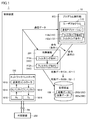
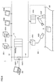
- FIG. 1 is a diagram showing a configuration example of an FA system 1 according to the present embodiment.
- the FA system 1 is a system for controlling the controlled objects such as equipment and devices and automating the production process.
- the FA system 1 includes a control device 10 and an external device 200.
- the external device 200 includes at least one of devices used in the production process such as an image sensor and an arm robot.
- An image sensor detects a character image etc. using the camera for image
- the external device 200 includes a server device such as a database system and a manufacturing execution system (MES).
- MES manufacturing execution system
- the arm robot executes a machining process on the workpiece.
- Examples of the network Ne that connects the control device 10 and the external device 200 include EtherNET (registered trademark) that is a general network protocol, EtherCAT (registered trademark) and EtherNet / IP (registered trademark) that are used as industrial network protocols. Trademark) or the like may be employed.
- EtherNET registered trademark
- EtherCAT registered trademark
- EtherNet / IP registered trademark
- the control device 10 includes a network controller 100, a program execution unit 103, a collection function 201, and a storage device 108.
- the network controller 100 provides an interface for the control device 10 to transmit and receive communication data to and from the external device 200 via the network Ne.
- the network controller 100 includes a Tx (transmission) buffer 1012, an Rx (reception) buffer 1014, a Tx (transmission) circuit 1016, an Rx (reception) circuit 1018, and a transmission / reception controller 1010 as main components.
- the reception circuit 1018 receives communication data transmitted from the external device 200 and writes the data to the reception buffer 1014.
- Communication data is a term that summarizes data transmitted over a network, and includes at least one of a packet and a frame.
- the transmission / reception controller 1010 sequentially reads communication data written in the reception buffer 1014.
- the transmission / reception controller 1010 outputs the read communication data to the program execution unit 103.
- the transmission / reception controller 1010 sequentially writes data to be transmitted to the external device 200 in the transmission buffer 1012.
- the transmission circuit 1016 sequentially outputs the data stored in the transmission buffer 1012 to the network Ne.
- the program execution unit 103 transmits / receives communication data to / from the network controller 100 by the communication application 111.
- the program execution unit 103 generates a control command for a control target according to a user program 110 that is arbitrarily created.
- the user program 110 is a control program implemented by the designer.
- the development tool for the user program 110 is installed in, for example, a support device as a PC (for example, the support device 300 shown in FIG. 6).
- the support device 300 will be described later.
- the designer can design the user program 110 according to the configuration of the external device 200 by combining a plurality of types of predetermined commands on the development tool.
- the commands that can be combined on the development tool include communication data filtering conditions and control commands for the external device 200.
- the control device 10 including the above configuration transmits / receives communication data to / from the external device 200 via the network Ne, and collects (captures) communication data that satisfies a predetermined filtering condition.
- the user program 110 includes a communication application 111 and a plurality of filtering conditions 112 (such as a filtering condition 112a and a filtering condition 112b).
- the communication application 111 is an application for communicating with the network controller 100 to transmit / receive communication data.
- the filtering condition 112 is a condition for filtering communication data, and is used when the collection function 201 filters and collects communication data.
- the collection function 201 changes the filtering condition 112 in accordance with instructions included in the user program 110 and executes communication data collection (capture). As described above, the collection function 201 can appropriately change the communication data to be filtered according to the filtering condition 112.
- the collection function 201 is a program for collecting communication data, and can be defined by various programs.
- the storage device 108 stores the collected data 202 (collected data 202a, collected data 202b, etc.) collected according to the filtering condition 112.
- the collected data 202 collected by the filtering condition 112 before the switching and the collected data 202 collected by the filtering condition 112 after the switching are different. It becomes. Specifically, the collected data 202a collected by the filtering condition 112a set according to the first command by the collecting function 201 and the collected data 202b collected by the filtering condition 112b set according to the next command can be different data.
- control apparatus 10 can arbitrarily change the filtering condition 112 in accordance with an instruction included in the user program 110.
- control apparatus 10 can change the content of the communication data to collect dynamically by changing the filtering condition of the collection function 201 according to the command included in the user program, and according to the processing status.
- the communication data to be collected can be varied as appropriate. Therefore, when an abnormality occurs in the communication data, only data for specifying the abnormality factor can be collected, and efficient use can be made with respect to the limited storage capacity of the control device 10.
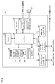
- FIG. 2 is a block diagram illustrating a hardware configuration example of a control device (hereinafter, also referred to as “controller”) 10 according to the present embodiment.
- the controller 10 includes a processor 102, a chipset 104, a main memory 106, and a storage device 108.
- the controller 10 includes a timer 116, a USB (Universal Serial Bus) interface 118, and a memory card interface 120.
- the controller 10 includes an internal bus controller 130, an upper network controller 100P1, and a field network controller 100P2.
- the processor 102 includes a CPU (Central Processing Unit), an MPU (Micro Processing Unit), a GPU (Graphics Processing Unit), and the like.
- a configuration having a plurality of cores may be adopted, or a plurality of processors 102 may be arranged.
- the controller 10 includes one or more processors 102 and / or a processor 102 having one or more cores.
- the chip set 104 realizes processing as the entire controller 10 by controlling the processor 102 and peripheral elements.
- the main memory 106 includes a volatile storage device such as DRAM (Dynamic Random Access Memory) and SRAM (Static Random Access Memory).
- the storage device 108 is configured by, for example, a nonvolatile storage device such as a flash memory.
- the processor 102 reads out various programs stored in the storage device 108, develops them in the main memory 106, and executes them, thereby realizing control according to the control target.
- the storage device 108 includes a system program 115 in addition to a user program 110 for executing basic processing of the control device 10.
- the user program 110 includes a filtering condition 112, and the system program 115 includes a collection function 201.
- the storage device 108 stores collected data 202 that is communication data that satisfies the filtering condition 112.
- the timer 116 is a device whose time is synchronized with the external device 200, and the external device 200 such as a camera or an arm robot is driven according to the time information of this timer.
- An example of information associated with the time information indicated by the timer 116 includes information indicating the coordinate position of the external device 200.
- the USB interface 118 mediates data communication with the device via the USB connection.
- the USB interface 118 enables connection with the support device 300 as an example.
- the memory card interface 120 is configured such that the memory card 122 is detachable, and can write data to the memory card 122 and read various data (such as user programs and trace data) from the memory card 122. ing.
- the host network controller 100P1 can mediate communication data with the external device 200 such as a server device via the network N1.
- the server device includes a database system and a manufacturing execution system (MES).
- MES manufacturing execution system
- the field network controller 100P2 can mediate communication data with the external device 200 such as a device used in the production process via the network N2.
- Devices used in the production process are an image sensor and a camera, a remote I / O device, an arm robot, and the like.
- the internal bus controller 130 mediates transmission / reception of communication data with the functional unit attached to the controller 10.
- FIG. 2 shows a configuration example in which necessary processing is realized by the processor 102 executing a program. However, some or all of the provided processing is performed by a dedicated hardware circuit (for example, an ASIC). Alternatively, it may be implemented using an FPGA or the like.
- a dedicated hardware circuit for example, an ASIC.
- FPGA field-programmable gate array
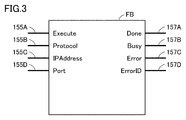
- FIG. 3 is an explanatory diagram of the function block FB according to the present embodiment.
- the collection function 201 changes the filtering condition in accordance with instructions included in the user program 110.
- a command included in the user program 110 is defined by a function block FB, for example.
- the function block FB includes an input unit 155A to an input unit 155D for receiving the setting of the filtering condition 112, and an output unit 157A to an output unit 157D for outputting the result of the filtering condition setting process.
- the input units 155A to 155D accept input of setting of the filtering condition 112. That is, the filtering condition 112 is changed according to the value input to the input units 155A to 155D. Examples of this value are specific values such as “Protocol”, “IP Address”, and “Port” as described below.
- the command included in the user program includes a command that clearly specifies the content of the filtering condition 112.
- the collection function 201 can arbitrarily change the filtering condition for collecting communication data by such a direct command.
- the input unit 155 ⁇ / b> A indicated as “Execute” accepts a setting for designating whether or not to change the filtering condition 112.
- the input unit 155A receives an input of “True” or “False”.
- the collection function 201 does not change the filtering condition 112.
- the collection function 201 executes a filtering condition changing process.
- the filtering condition 112 input to the other input units 155B to 155D is set as a new filtering condition 112.
- the controller 10 can directly change the filtering condition 112 in accordance with an instruction included in the user program 110.
- the input unit 155B indicated as “Protocol” receives an input for specifying a communication protocol of communication data to be filtered.
- the input unit 155B receives input of identification information of a communication protocol.
- the identification information may be designated by a communication protocol name, or may be designated by a communication protocol ID (Identification).
- the input unit 155B receives an input of “TCP” or “FTP”.
- TCP Transmission Control Protocol
- FTP communication protocol
- the collection function 201 changes the filtering condition 112 so that communication data according to the TCP protocol is a filtering target.
- the collection function 201 changes the filtering condition so that communication data according to the FTP protocol is a filtering target.
- the controller 10 can arbitrarily change the protocol condition, which is one of the conditions for collecting communication data.
- the input unit 155C indicated as “IP Address” receives an input for designating an IP address corresponding to a communication data device to be filtered. For example, when “10.0.0.1” is input to the input unit 155C, the collection function 201 transmits communication data transmitted to the device (destination device) having the IP address “10.0.0.1”.
- the filtering condition 112 is changed so as to be a filtering target. As described above, the controller 10 can arbitrarily change the IP address condition, which is one of the conditions for collecting communication data.
- the input unit 155D indicated as “Port” receives an input for designating the port number of the communication data device to be filtered.
- the collection function 201 changes the filtering condition 112 so that communication data sent to the port number “80” of the transmission destination device is a filtering target.
- the controller 10 can arbitrarily change the port number, which is one of the conditions for collecting communication data.
- the controller 10 can arbitrarily change the filtering condition 112 for each item in accordance with an instruction included in the user program 110.
- a signal indicating normal end is output from the output unit 157A indicated as “Done”. While the filtering condition 112 is being changed, a signal indicating that the change process is being performed is output from the output unit 157B indicated as “Busy”. If the filtering condition 112 is not properly set, a signal indicating abnormal termination is output from the output unit 157C indicated as “Error”. In this case, an error ID for identifying the content of the error is further output from the output unit 157D indicated as “Error ID”.
- the function block FB may be provided with various input units and output units in addition to the input units 155A to 155D and the output units 157A to 157D.
- an input unit for designating a communication interface may be provided in the function block FB.
- FIG. 4 is a diagram illustrating an example of a user program in which the function block FB described with reference to FIG. 3 is incorporated.
- the user program 110 is defined by a ladder program.
- the user program 110 is defined so as to change the filtering condition 112 of communication data in accordance with the work process of the external device 200.
- the collection function 201 starts collecting communication data on condition that a variable that can be used in the user program indicating the state of the work process is a predetermined value.
- the work process refers to a process from when one or a plurality of external devices 200 starts work of a target process to when it finishes.
- the user program 110 shown in FIG. 4 does not indicate the entire processing in the controller 10, and for example, a part of logic at the time of switching each work process is omitted.
- the user program 110 is defined by input elements IN0 to IN10, function blocks FB0 to FB2, and output elements OUT0 to OUT2.
- Each of the function block FB1 and the function block FB2 corresponds to the function block FB described in FIG.
- the values of input elements IN0 to IN10 vary according to the assigned variable. More specifically, a variable “ChangeTrigger” is assigned to the input element IN0.
- the value of the variable “ChangeTrigger” changes to “True” (ON) based on the activation of the controller 10. In other cases, the value of the variable “ChangeTrigger” is “False” (OFF).
- the variable “Busy0” is assigned to the input element IN1.
- the variable “Busy0” is a BOOT type.
- the variable “Busy0” is associated with the output “Busy” of the function block FB1. Therefore, the value of the input element IN1 changes according to the value of the output “Busy” of the function block FB1.
- the variable “Busy1” is assigned to the input element IN2.
- the variable “Busy1” is of the BOOT type.
- the variable “Busy1” is associated with the output “Busy” of the function block FB2. Therefore, the value of the input element IN2 changes according to the value of the output “Busy” of the function block FB2.
- the variable “Done 0” is assigned to the input element IN3.
- the variable “Done0” is associated with the output “Done” of the function block FB1.
- the variable “Done1” is assigned to the input element IN4.
- the variable “Done1” is associated with the output “Done” of the function block FB2.
- the variable “Error0” is assigned to the input element IN5.
- the variable “Error0” is associated with the output “Error” of the function block FB1.
- the variable “Error1” is assigned to the input element IN6.
- the variable “Error1” is associated with the output “Error” of the function block FB2.
- the variable “SettingTrigger” is assigned to the input element IN7.
- the variable “PA” is assigned to the input element IN8.
- a control function for realizing the work process A is defined in the user program 110.
- the control function outputs a control command to the external device 200 according to the specified control content.
- the variable “SettingTrigger” is assigned to the input element IN9.
- the variable “PB” is assigned to the input element IN10.
- a control function for realizing the work process B is defined in the user program 110.
- the control function outputs a control command to the external device 200 according to the specified control content.
- the function block FB0 is a program for executing a reset process executed at the start of the work process A or at the start of the work process B.
- the function block FB0 includes input units “Set” and “Reset1” and an output unit “Q1”.
- the function block FB0 starts the reset process for the work process A based on the signal indicating the validity being input to both the input units “Set” and “Reset1”.
- the function block FB1 includes “TCP” input to the input unit “Protocol”, “10.0.0.1” input to the input unit “IP Address”, and the input unit “Port”.
- the filtering condition 112 according to “80” input to “” is set as a new filtering condition 112. Details of the method of changing the filtering condition 112 are as described with reference to FIG. 3, and therefore the description thereof will not be repeated.
- the function block FB2 includes “FTP” input to the input unit “Protocol”, “10.0.0.2” input to the input unit “IP Address”, and the input unit “Port”.
- the filtering condition 112 according to “20” input to “” is set as a new filtering condition 112. That is, the filtering condition 112b set in the function block FB2 is different from the filtering condition 112a set in the function block FB1.
- the controller 10 can adjust the collection timing of communication data to an arbitrary timing. Specifically, the controller 10 can adjust the collection timing of communication data according to the state of the work process.
- the values of the output elements OUT0 to OUT2 change according to the output value of the associated function block.
- the variable “SettingTrigger” is assigned to the output element OUT0.
- the output element OUT0 is associated with the output “Q1” of the function block FB0. As a result, the value of the output element OUT0 changes according to the value of the output “Q1”.
- the variable “Done 0” is assigned to the output element OUT1.
- the output element OUT1 is associated with the output “Done” of the function block FB1.
- the value of the output element OUT1 changes according to the value of the output “Done” of the function block FB1.
- the variable “Done1” is assigned to the output element OUT2.
- the output element OUT2 is associated with the output “Done” of the function block FB2. As a result, the value of the output element OUT2 changes according to the value of the output “Done” of the function block FB2.
- the filtering condition 112a input to the function block FB1 is set in the work process A according to the value of the variable indicating the state of the work process, and the function block FB2 is filtered in the work process B.
- the condition 112b is set as appropriate.
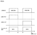
- FIG. 5 is a diagram illustrating a correspondence relationship between the start and end of the work process and the change of the filtering condition.
- FIG. 5 shows the execution state of the work process over time (msec), the values of variables indicating the start and end of the work process, and the filtering conditions set in accordance with the work process.
- work process A is executed.
- the filtering condition 112a (filtering condition 1) is set in the collection function 201 according to the command included in the user program. Is done.
- the collection function 201 is based on the filtering condition 112a. Terminate communication data collection.
- the collection function 201 transmits communication data based on the filtering condition 112b. End collection.
- FIG. 6 is a schematic diagram showing a schematic configuration of the FA system 1 according to the present embodiment.
- the FA system 1 includes a controller 10, an external device 200, and a support device 300.
- the controller 10 can be connected to a plurality of networks.
- the communication port 200P1 of the controller 10 is connected to the upper network N1, and the communication port 200P2 is connected to the lower network N2.
- EtherNET registered trademark
- EtherNET registered trademark
- the networks N1 and N2 are not limited to these, and any communication means can be adopted.
- the external device 200 in the upper network N1 includes, for example, at least one of a server device 200A and a display device 200B.
- the server apparatus 200A is assumed to be a database system, a manufacturing execution system (MES), or the like.
- the manufacturing execution system acquires information from a manufacturing apparatus or facility to be controlled, monitors and manages the entire production, and can handle order information, quality information, shipping information, and the like.
- the present invention is not limited thereto, and an apparatus that provides an information system service (a process of acquiring various types of information from a control target and performing macroscopic or microscopic analysis) may be connected to the network N1.
- the controller 10 sets communication data acquired according to a work process executed by the server device 200 ⁇ / b> A as a filtering target through cooperation between the user program 110 and the collection function 201.
- the filtering condition 112 corresponding to the work process of the server device 200A is changed on condition that a variable that can be used in the user program 110 indicating the work process state of the server device 200A is a predetermined value. Thereby, the filtering condition 112 of the function block is changed.
- the collection function 201 filters and collects communication data based on the changed filtering condition.
- the display device 200B graphically displays the calculation result in the controller 10 and outputs a command corresponding to the user operation to the controller 10 in response to an operation from the user.
- the controller 10 sets communication data acquired according to the work process executed by the display device 200 ⁇ / b> B as a filtering target through cooperation between the user program 110 and the collection function 201.
- the filtering condition 112 corresponding to the work process of the display device 200B is set on condition that a variable that can be used in the user program 110 indicating the work process state of the display device 200B is a predetermined value. Thereby, the filtering condition 112 of the function block is changed.
- the collection function 201 filters and collects communication data based on the changed filtering condition 112.
- the support device 300 provides a designer with a development environment for designing the user program 110.
- the support device 300 is, for example, a notebook PC, a desktop PC, a tablet terminal, or a smartphone.
- the designer can design the user program 110 on the support device 300 and download the user program 110 to the controller 10 via the USB interface 118.
- the external device 200 in the lower network N2 includes, for example, at least one of an image sensor 200C and a camera 200D, a remote I / O device 200E, and an arm robot 200F.
- the controller 10 and the external device 200 in the lower network N2 are sequentially connected in a daisy chain, for example.
- the image sensor 200C performs, for example, an operation process of performing image measurement processing such as pattern matching on the image data of the workpiece W imaged by the camera 200D and transmitting the processing result to the controller 10.
- the collection function 201 filters and collects communication data based on the changed filtering condition 112.
- the remote I / O device 200E controls the arm robot 200F according to the control command of the controller 10.
- the controller 10 outputs a control command for causing the arm robot 200F to perform a predetermined work process to the remote I / O device 200E according to the work process by the image sensor 200C.
- the remote I / O device 200E controls the arm robot 200F according to the control command.
- the remote I / O device 200E gives a control command so as to remove the workpiece W determined to have poor inspection quality from the conveyor.
- the state of the arm robot 200F (for example, the position and angle of each joint) is sequentially fed back from the remote I / O device 200E to the controller 10.
- the collection function 201 filters and collects communication data based on the changed filtering condition.
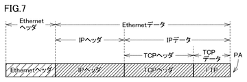
- FIG. 7 is a diagram showing an example of communication data to be filtered according to the present embodiment.
- an example of communication data to be filtered by the controller 10 will be described with reference to FIG.
- the communication data to be filtered by the controller 10 includes, for example, a communication packet according to the TCP / IP protocol.
- the external device 200 that is a transmission source device divides data to be transmitted into a plurality of communication packets, and sequentially transmits each communication packet to the controller 10.
- one of the communication packets divided by the transmission source device is shown as a communication packet PA.
- the communication packet PA includes an Ethernet header that is a header portion of the Ethernet protocol and Ethernet data that is a data portion of the Ethernet protocol.
- the Ethernet data includes an IP header that is a header portion of the IP protocol and IP data that is a data portion of the IP protocol.
- the IP data is composed of a TCP header that is a header part of the TCP protocol and TCP data that is a data part of the TCP protocol.
- the IP header of the communication packet PA includes the IP address of the external device 200 (for example, the server device 200A) that is the transmission source device, the IP address of the controller 10 that is the transmission destination device, and the communication protocol.
- the TCP header of the communication packet PA includes the port number of the transmission source device and the port number of the transmission destination device.
- the TCP data of the communication packet PA includes the content of data to be transmitted.
- the data to be transmitted includes, for example, various variables indicating the state of the external device 200, acquisition commands for various variables, and the like.
- the variable here refers to various variables included in the user program 110. The variable changes according to the state of various components of the external device 200.
- the controller 10 Based on the reception of the communication packet PA, the controller 10 extracts information for comparison with the filtering condition 112 from the communication packet PA.
- the information includes, for example, at least one of an IP address of the transmission source device, an IP address of the transmission destination device, a communication protocol, a port number of the transmission source device, and a port number of the transmission destination device.
- the controller 10 determines whether the information extracted from the communication packet PA satisfies the filtering condition 112. When it is determined that the information extracted from the communication packet PA satisfies the filtering condition 112, the controller 10 sets the communication packet PA as a filtering target.
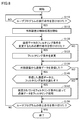
- FIG. 8 is a flowchart representing a part of processing executed by controller 10 according to the present embodiment.
- the processing shown in FIG. 8 is realized by the collection function 201 changing the filtering condition in accordance with an instruction included in the user program 110 of the controller 10. In other aspects, some or all of the processing may be performed by circuit elements or other hardware.
- step S110 the program execution unit 103 of the controller 10 determines whether an execution instruction of the user program 110 has been received.
- program execution unit 103 determines that an execution instruction for user program 110 has been received (YES in step S110)
- control is switched to step S112.
- step S110 NO the program execution part 103 performs the process of step S110 again.
- step S112 the program execution unit 103 executes initialization processing such as establishment of communication with the external device 200. Thereafter, the program execution unit 103 executes a control function defined in the user program 110 and starts control of the external device 200.
- step S120 If the program execution unit 103 determines that an execution instruction for changing the filtering condition 112 has been received (YES in step S120), the program execution unit 103 switches the control to step S122. Otherwise (NO in step S120), processor 102 switches control to step S130.
- step S122 the program execution unit 103 outputs instructions included in the user program 110 to the collection function 201.
- the collection function 201 changes the filtering condition in accordance with instructions included in the user program 110.
- the collection function 201 changes the values input to the input units 155B to 155D shown in FIG. Since the filtering condition changing method is as described with reference to FIG. 3, the description thereof will not be repeated.
- step S130 the program execution unit 103 determines whether or not any communication data has been received from the external device 200.
- program execution unit 103 determines that any communication data has been received from external device 200 (YES in step S130)
- program execution unit 103 switches control to step S140. If not (NO in step S130), program execution unit 103 switches control to step S150.
- step S140 the collection function 201 determines whether or not the communication data satisfies the currently set filtering condition.
- This communication data is, for example, data transmitted from the external device 200 to the program execution unit 103 via the network controller 100.
- the collection function 201 compares at least one of identification information (for example, IP address) of the external device 200, a port number of the external device 200, and a communication protocol used when receiving communication data with the filtering condition. Extracted from communication data as comparison information.
- step S140 When the comparison information matches the filtering condition (YES in step S140), the program execution unit 103 switches the control to step S142. Otherwise (NO in step S140), program execution unit 103 switches control to step S150.
- step S142 the collection function 201 collects communication data according to the set filtering condition.
- the collection function 201 stores the collected communication data in the storage device 108.
- step S150 the program execution unit 103 determines whether a stop instruction for the user program 110 has been received. If program execution unit 103 determines that a stop instruction for user program 110 has been received (YES in step S150), it ends the process shown in FIG. Otherwise (NO in step S150), program execution unit 103 returns control to step S120.
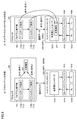
- FIG. 9 is a diagram showing a place where processing of user program 110 and collection function 201 according to the present embodiment is executed.
- FIG. 9 a specific configuration example having the user program 110 and the collection function 201 of the controller 10 will be described.
- the network controller 100 (100P1, 100P2) and the processor 102 shown in FIGS. 9A and 9B have the same basic configuration as the configuration described in FIGS.
- FIGS. 9A and 9B show a specific configuration example having a user program 110 and a collection function 201 that executes a filtering process in accordance with instructions included in the user program 110.
- the processing of the user program 110 is executed by the processor 102. That is, the processor 102 can change the filtering condition of the collection function 201 in accordance with an instruction included in the user program. Therefore, the processing of the collection function 201 is executed by the processor 102 as with the user program 110.
- the processing of the user program 110 is executed by the processor 102. That is, the processor 102 can change the filtering condition of the collection function 201 in accordance with an instruction included in the user program.
- the processing of the collection function 201 is executed by the transmission / reception controller 1010 of the network controller 100, unlike the user program 110.
- the collection function 201 can be executed by either the processor 102 or the network controller 100, and the function can be flexibly replaced according to the processing load of each apparatus and the purpose of use of the user.
- the program execution unit 103 of the controller 10 transmits and receives communication data to and from the network controller 100. And the program execution part 103 produces
- the collection function 201 allows the communication data filtering condition 112 to be changed in accordance with instructions included in the user program 110.
- control apparatus 10 can change the content of the communication data to collect dynamically by making it possible to change the filtering conditions of the collection function 201 in accordance with the instructions included in the user program, depending on the processing status.
- the communication data to be collected can be appropriately changed. Therefore, when an abnormality occurs in the communication data, only data for specifying the abnormality factor can be collected, and efficient use can be made with respect to the limited storage capacity of the control device 10.
- FIG. 10 is a block diagram showing a hardware configuration example of the controller 10 according to the present embodiment.
- the configuration of FIG. 10 includes the same configuration as the hardware configuration example of FIG. In the description of FIG. 10, a description of the same configuration as that of FIG. 2 will not be repeated, and a different configuration will be described.
- 10 includes a filtering condition table 501 in addition to the user program 110, the system program 115, and the collected data 202.
- the filtering condition table 501 is a table for managing filtering conditions generated by the user using the support device 300.
- the storage device 108 of the controller 10 stores the generated filtering condition table 501.
- the storage device 108 is described as storing the filtering condition table 501 separately from the user program 110, but the filtering condition table 501 may be included in the user program 110.
- FIG. 11 is a diagram illustrating an example of the filtering condition table 501.
- the filtering condition table 501 has a Number item 502, a designation method item 503, and an IP address item 504. Further, the filtering condition table 501 includes items (parameters) of a subnet mask item 505, a protocol item 506, a Range item 507, a Port1 item 508, and a Port2 item 509.
- the Number item 502 is an index in which values (parameter values) of a plurality of items of filtering conditions are grouped.
- the filtering condition 112 is clearly shown in the user program 110, and the collection function 201 performs processing for changing the filtering condition in accordance with such an instruction that directly indicates the parameter value of the filtering condition.
- the collection function 201 performs processing for changing the filtering condition in accordance with such an instruction that directly indicates the parameter value of the filtering condition.
- the values of parameters with different filtering conditions are defined as one group, and each of the plurality of groups is defined by an index (for example, a number).
- the index defined in this way is information indicating which of the plurality of filtering conditions is effective, and corresponds to an instruction included in the user program 110.
- the collection function 201 can arbitrarily change the filtering condition according to such an instruction that indirectly indicates the parameter value of the filtering condition.
- one index is associated with the value of one item.
- Each item of the designation method item 503, the IP address item 504, and the subnet mask item 505 included in the table of FIG. 11 is an item related to the network layer which is layer 3 (L3).
- the support device 300 enables the input of other items by designating the designation method item 503 by a user operation.
- Specific examples of the contents of the designation method item 503 include “IP designation” for designating an IP address, “Interface Network”, “any”, etc. for not designating a specific item.
- IP designation for designating an IP address
- the subnet mask item 505 when “IP designation” is selected in the designation method item 503, specific values can be input by the user.
- the support apparatus 300 sets the values of the items related to the layer 3 of the filtering condition table 501 by receiving the IP address and subnet mask values from the user for these items.
- each of the protocol item 506, the Range item 507, the Port1 item 508, and the Port2 item 509 included in the table of FIG. 11 is an item related to the transport layer that is Layer 4 (L4).
- L4 Layer 4
- FIG. 11 by setting a check in the Range item 507 by a user operation, setting between ports can be performed. For example, after a check is input in the Range item 507 by the user's operation, “80” is input in the Port1 item and “100” is input in the Port2 item, so that communication data between the port 80 and the port 100 is input. It is possible to set conditions for filtering.
- Such input between ports may be performed by a method other than inputting a check in the Range item 507. For example, without providing the Range item, the user may directly input a plurality of numerical values into the Port 1 and Port 2 items, or a value indicating between ports, such as “80-100”, for one item. The user may input directly.
- the support device 300 receives the user's input of the protocol type, port number range setting, and port number from the user for these items, and the values of the items related to layer 4 of the filtering condition table 501 Set. If “TCP” is selected in the protocol item 506, it means that an arbitrary protocol (for example, HTTP) using TCP is selected in the layer 4.
- TCP Transmission Control Protocol
- the filtering condition table 501 generated in this way includes a plurality of filtering conditions.
- the support device 300 stores the filtering condition table 501 in the storage device 108 of the controller 10.
- the filtering condition table 501 the setting for the items related to the layers 3 and 4 has been described. However, the values for the items related to other layers such as the application layer and the data link layer may be set.
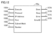
- FIG. 12 is an explanatory diagram of the function block FBa according to the present embodiment.
- the basic configuration of the function block FBa in FIG. 12 is the same as the function block FB described in FIG.
- the input unit 155F indicated as “Number” receives an input of an index (for example, a number) obtained by grouping a plurality of items set in the filtering condition table 501.
- the input unit 155F indirectly sets the filtering condition. It is possible to set the filtering conditions by receiving the values shown in FIG.
- the input unit 155E indicated as “Subnet Mask” receives an input of a value for designating the subnet mask of the filtering condition table 501.
- FIG. 13 is a diagram showing an example of a user program incorporating the function block FBa described in FIG. 12 according to the present embodiment.
- the ladder program of FIG. 13 has the same contents as the ladder program described with reference to FIG.
- the contents of the input unit “Number” and the input unit “Subnet Mask” corresponding to such a partial configuration will be described using function blocks FB3 and FB4 shown in FIG.
- the function block FB3 sets a value input to another input unit according to a value input to the input unit “Number”. Specifically, when the value input to the input unit “Number” is “1”, the value of each item corresponding to the Number “1” in the filtering condition table 510 described in FIG. 11 is set in another input unit. Is done. Specifically, “TCP” is set in the input unit “Protocol” as indicated by a function block FB3 in FIG. Also, “10.0.0.1” is set in the input unit “IP Address”, and “80” is set in the input unit “Port”. Furthermore, “255.255.255.0” is set in the input unit “Subnet Mask”.
- the function block FB4 sets a value input to another input unit according to a value input to the input unit “Number”. Specifically, when the value input to the input unit “Number” is “2”, the value of each item corresponding to the number “2” in the filtering condition table 501 described in FIG. 11 is set in another input unit. Is done. Specifically, the input unit “Protocol” is “FTP”, the input unit “IP Address” is “10.0.0.2”, the input unit “Port” is “20”, and the input unit “Subnet Mask”. Is set to “255.255.255.0”.
- the values of a plurality of parameters defined in advance in the table are set as input values of the other input units.
- the instruction included in the user program 110 includes information indicating which condition is effective among the plurality of filtering conditions included in the filtering condition table 510 stored in the storage device 108 in advance (for example, Number's Value). Since the filtering condition can be changed by the information indicating the filtering condition indirectly, it is possible to easily set the target of communication data to be collected according to the processing status of the work process as an arbitrary target of the user.
- the filtering condition changing process based on the filtering condition table 501 stored in the storage device 108a may be executed by the processor 102 or the network controller 100.
- FIG. 14 is a diagram showing an example of filtering condition generation processing using support device 300 according to the present embodiment.
- the support device 300 acquires communication data output from the controller 10.
- the processor 102 of the controller 10 stores the communication data received by the network controller 100 in the storage device 108.
- the controller 10 executes processing for outputting the communication data 156 stored in the storage device 108 to the support device 300.
- the support device 300 displays the communication data 156 acquired from the controller 10 on the display unit 310.
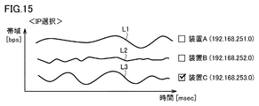
- FIG. 15 is a diagram showing a time transition of a change in communication speed of communication data of a plurality of external devices 200 (IP addresses) according to the present embodiment.
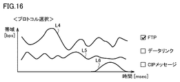
- FIG. 16 is a diagram showing a time transition of a communication speed change of communication data of a plurality of protocols according to the present embodiment. 15 and FIG. 16, the vertical axis indicates the communication speed (bps) of communication data per unit time, and the horizontal axis indicates time (msec).
- FIG. 15 shows transition lines L1 to L3 of communication speeds of the three external devices 200 (external device A to external device C). Specifically, the external device A corresponds to the transition line L1, the external device B corresponds to the transition line L2, and the external device C corresponds to the transition line L3.
- FIG. 16 shows transition lines L4 to L6 of communication speeds of three protocols (FTP, data link, CIP message). Specifically, FTP corresponds to the transition line L4, the data link corresponds to the transition line L5, and the CIP message corresponds to the transition line L6.
- FTP corresponds to the transition line L4
- data link corresponds to the transition line L5
- CIP message corresponds to the transition line L6.
- the display unit 310 of the support device 300 displays a plurality of transition lines L1 to L6 in FIGS. 15 and 16 to the user.
- a user who operates the support device 300 selects, for example, a device (for example, the external device C) corresponding to the transition line L3 whose communication speed is lower than that of the other external devices 200 among the plurality of external devices 200.
- the user who operates the support device 300 selects, for example, a protocol (for example, FTP protocol) corresponding to the transition line L4 in which the fluctuation range of the communication speed is larger than other protocols among a plurality of protocols. In this way, the support device 300 selects the value of each item used for generating the filtering condition by a user operation.
- IP addresses IP addresses
- three protocols have been described as examples, but the number of devices and protocols and types to be selected may be other than these. Good. Specifically, the number of devices and protocols may be two or less or four or more, and the type to be selected may be a MAC address or the like.
- the processor 102 may output all the communication data to the support device 300 without performing the filtering of the communication data 156, or The filtering data may be set and the communication data after filtering may be output to the support device 300.
- the support apparatus 300 generates a filtering condition using each item related to the filtering condition selected by the user.
- FIG. 17 is a diagram for explaining an example of the filtering condition generated by selecting each item related to the filtering condition according to the present embodiment.
- the filtering condition table 501a shown in FIG. 17 is basically the same as the filtering condition table 501 described with reference to FIG.
- the different contents are as follows.
- Each item of layer 3 (L3) and layer 4 (L4) in “6” of the Number item 502 includes the items of the external device A selected by the user by operating the support device 300 in the description of FIGS. 15 and 16.
- Values of the IP address (192.268.251.0) and the protocol (FTP) are input to the IP address item 504 and the protocol item 506.
- the values of the subnet mask item 505 and the Port1 item 508, which are related items are also input. If “TCP” is selected in the protocol item 506, it means that an arbitrary protocol (for example, HTTP) using TCP is selected in the layer 4.
- the support apparatus 300 transfers the generated filtering condition table 501a to the controller 10.
- the controller 10 stores the filtering condition table 501 a acquired from the support device 300 in the storage device 108.
- the user can arbitrarily generate a filtering condition according to the communication state while confirming the state of the communication speed of the communication data using the support device 300.
- the support apparatus 300 has been described with respect to generating the filtering condition by the user's selection.
- the support device 300 may automatically select items relating to the filtering condition without depending on the user's selection. Specifically, a protocol item whose communication speed is equal to or lower than a predetermined speed is automatically selected. Thereby, the support apparatus 300 can generate
- the controller 10 can collect communication data by changing to an optimal filtering condition according to the communication status.
- FIG. 18 is a diagram showing another example of the flow of the filtering condition generation process using the support device 300 according to the present embodiment.
- the filtering condition generation process in FIG. 14 described above the example in which the user uses the support device 300 to generate the filtering condition based on the communication speed change of the communication data 156 has been described.
- FIG. 18 illustrates an example in which the filtering condition is generated based on the number of occurrences (frequency) of communication abnormality.
- the support device 300 acquires abnormality occurrence data output from the controller 10.
- the processor 102 of the controller 10 in FIG. 18 stores the communication data received by the network controller 100 in the storage device 108 and executes processing for outputting the abnormality occurrence data 158 to the support device 300.
- the abnormality occurrence data is a value indicating the number of times the communication data has occurred, for example, a value indicating the number of times of timeout or retry for the communication data.
- the controller 10 may automatically count the number of timeouts and the number of retries related to communication data, and the user may check the communication status using the support device 300 while the controller 10 automatically counts the value indicating the number of occurrences of abnormality. 300 may be operated and counted.
- the support device 300 displays the abnormality occurrence data 158 acquired from the controller 10 on the display unit 310.
- FIG. 19 is a diagram showing an example of an image related to the number of occurrences of communication data abnormality, which is an image displayed on display unit 310 of support device 300 according to the present embodiment.
- the image relating to the number of occurrences of abnormality in FIG. 19 includes a time item 602, a selection item 603, a timeout number item 605, and a retry number item 606.
- the time item 602 can set a time zone between the current few minutes and several hours ago by the user's operation. Specifically, the time item 602 allows the user to set an arbitrary time zone from a plurality of time zones such as “last 30 minutes”, “last 1 hour”, and “last 2 hours”.
- zone of every 30 minutes or 1 hour of the said time item 602 is an illustration, and the time slot
- “Last 1 hour” of the time item 602 is selected by the user, and the type of protocol of communication data generated during the past 1 hour from the present time and the number of occurrences of abnormality according to the protocol type Indicated.
- the support apparatus 300 generates a filtering condition using an item related to the filtering condition selected by the user.
- the generation of the filtering condition is the same as the process described with reference to FIG.
- the support apparatus 300 transfers the generated filtering condition table 501a to the controller 10.
- the controller 10 stores the filtering condition table 501 a acquired from the support device 300 in the storage device 108. In this manner, the user can generate a filtering condition according to the communication state while confirming the number of occurrences of communication data abnormality using the support device 300.
- the support apparatus 300 has been described with respect to generating the filtering condition by the user's selection.
- the support device 300 may automatically select items relating to the filtering condition without depending on the user's selection. More specifically, protocol items whose number of occurrences of abnormality is equal to or greater than a predetermined number may be automatically selected. In the example of FIG. 19, one of the items has been described as a protocol. However, the item is not limited to a protocol, and may include other items such as an IP address, a port number, and a MAC address.
- the support apparatus 300 can generate
- the controller 10 can collect communication data by changing to an optimal filtering condition according to the communication status.
- the user program 110 may be defined to change the filtering condition according to other situations.
- the user program 110 may be defined to set a filtering condition according to the device configuration of the FA system 1 when the device configuration of the external device 200 in the FA system 1 changes. Thereby, for example, when an unintended communication device is connected to the controller 10, the controller 10 can block the communication device.
- a method for detecting the connection / disconnection of a communication device a method using a function block for monitoring a network state can be considered. The function block periodically monitors the state of the network table, and detects the connection / disconnection of the communication device from the change information of the network table.
- the user program 110 when the user program 110 receives a malicious attack from an external device, the user program 110 may be defined to set a filtering condition for preventing the malicious attack.
- the communication driver of the controller 10 monitors the amount of received data per unit time (for example, the number of received packets per unit time), and when the amount of received data exceeds a predetermined threshold, malicious communication from an external device. Determine that you are under attack.
- the collection function 201 blocks the external device performing the malicious attack based on information such as an IP address and a port number.
- the collection function 201 may block reception of all communication packets.
- the user program 110 may be defined to set a filtering condition according to the connection status when the communication connection status of the controller 10 changes.
- the collection function 201 allows the reception data from the transmission source device to pass only after the communication with the transmission source device is established until the communication device 201 is disconnected, otherwise from the transmission source device. Block received data. As a result, the collection function 201 allows the communication data to pass only for a necessary period, so that security can be improved.
- the present embodiment includes the following disclosure.
- the collection unit (201) is a control device configured to be able to change the filtering condition (112) in accordance with an instruction included in the user program (110).
- a control method for controlling a control object Generating a control command for the control object according to a user program (110) arbitrarily created; (S112); A step (S112) of transmitting / receiving communication data to / from an external device (200) via the network (Ne); Collecting data satisfying a filtering condition (112) among the communication data transmitted to the network (Ne) (S142),
- the collecting step (S142) is a control method configured such that the filtering condition (112) can be changed in accordance with an instruction included in the user program (110).
- a control program for a control device for controlling a control object The control program is stored in the control device. Generating a control command for the control object according to a user program (110) arbitrarily created; (S112); Transmitting and receiving communication data to and from an external device via the network (Ne) (S112); Collecting the data satisfying the filtering condition (112) among the communication data transmitted to the network (Ne) (S142),
- the collecting step (S142) is a control program configured such that the filtering condition (112) can be changed in accordance with an instruction included in the user program (110).
Landscapes
- Engineering & Computer Science (AREA)
- General Engineering & Computer Science (AREA)
- Manufacturing & Machinery (AREA)
- Quality & Reliability (AREA)
- Physics & Mathematics (AREA)
- General Physics & Mathematics (AREA)
- Automation & Control Theory (AREA)
- Computer Networks & Wireless Communication (AREA)
- Signal Processing (AREA)
- Programmable Controllers (AREA)
- Small-Scale Networks (AREA)
Abstract
制御装置は、任意に作成されるユーザプログラムに従って、制御対象に対する制御命令を生成するプログラム実行部と、ネットワークを介して外部装置との間で通信データを送受信する通信部と、通信部に接続されネットワークに伝送される前記通信データのうち、フィルタリング条件を満たすデータを収集する収集部とを備える。収集部は、前記ユーザプログラムに含まれる命令に従って、前記フィルタリング条件を変更可能に構成される。
Description
本開示は、制御装置により通信データを収集する技術に関する。
FA(Factory Automation)を用いた生産現場では、PLC(Programmable Logic Controller)やロボットコントローラなどの産業用の制御装置が導入されている。制御装置は、ネットワークにより通信可能な種々の産業用の駆動機器である外部装置を制御することで、生産工程を自動化することができる。このような制御装置に関して、特開2011-35664号公報(特許文献1)は、制御装置にプロトコル機能を内蔵して、フレーム等の通信データをキャプチャするといったデータの収集が行える設備システムを開示している。
また、特開2012-156695号公報(特許文献2)は、パケット等の通信データの転送エンジンは、ユーザが予め設定したフィルタ条件に一致したパケットが存在した場合に、そのデータをコピーし、制御用プロセッサに出力する通信データの収集装置を開示している。
ところで、ネットワークにおける通信に異常が生じた場合、その異常要因を特定するための有効な機能の一つとして通信データを収集する機能がある。FAにおけるネットワークでは高速で定周期に通信する必要があることから通信データのデータ量が多くなる場合がある。このような場合、制御装置の限られたメモリ容量では異常要因を特定できるだけのデータを取得できないことがある。
本開示は上述のような問題点を解決するためになされたものであって、ある局面における目的は、処理状況に応じて収集の対象を適宜異ならせることで効率的な記憶容量の利用が可能な技術を提供することである。
本開示の一例では、制御装置は、任意に作成されるユーザプログラムに従って、上記制御対象に対する制御命令を生成するプログラム実行部と、ネットワークを介して外部装置との間で通信データを送受信する通信部と、上記通信部に接続され上記ネットワークに伝送される上記通信データのうち、フィルタリング条件を満たすデータを収集する収集部とを含む。上記収集部は、上記ユーザプログラムに含まれる命令に従って、上記フィルタリング条件を変更可能に構成される。
この開示によれば、制御装置は、ユーザプログラムに含まれる命令に従って、フィルタリング条件を任意に変更できる。
本開示の一例では、上記ユーザプログラムに含まれる命令は、上記フィルタリング条件の内容を明示する命令を含む。
この開示によれば、制御装置は、ユーザプログラムに含まれる命令に従って、フィルタリング条件を直接的に変更できる。
本開示の一例では、予め設定された複数のフィルタリング条件を格納する格納部をさらに含む。上記ユーザプログラムに含まれる命令は、上記複数のフィルタリング条件のうちのいずれの条件が有効であるかを示す情報を含む。
この開示によれば、制御装置は、ユーザプログラムに含まれる命令に従って、フィルタリング条件を間接的に変更できる。
本開示の一例では、上記フィルタリング条件は、IPアドレス、プロトコル、および、ポート番号の少なくとも1つを含む。
この開示によれば、制御装置は、ユーザプログラムに含まれる命令に従って、フィルタリング条件を項目ごとに任意に変更できる。
本開示の一例では、上記ユーザプログラムで利用可能な変数が所定値であることを条件に、上記収集部による上記通信データの収集を開始させる。
この開示によれば、制御装置は、通信データの収集タイミングを任意のタイミングに調整できる。
本開示の一例では、上記変数の値は、上記外部装置による作業工程の状態を示す値である。
この開示によれば、制御装置は、通信データの収集タイミングを作業工程の状態に応じて調整できる。
本開示の他の例では、制御対象を制御するための制御方法は、任意に作成されるユーザプログラムに従って、上記制御対象に対する制御命令を生成するステップと、ネットワークを介して外部装置との間で通信データを送受信するステップと、上記ネットワークに伝送される上記通信データのうち、フィルタリング条件を満たすデータを収集するステップとを含む。上記収集するステップは、上記ユーザプログラムに含まれる命令に従って、上記フィルタリング条件を変更可能に構成される。
この開示によれば、制御方法は、ユーザプログラムに含まれる命令に従って、フィルタリング条件を任意に変更できる。
本開示の他の例では、制御対象を制御するための制御装置の制御プログラムは、上記制御装置に、任意に作成されるユーザプログラムに従って、上記制御対象に対する制御命令を生成するステップと、ネットワークを介して外部装置との間で通信データを送受信するステップと、上記ネットワークに伝送される上記通信データのうち、フィルタリング条件を満たすデータを収集するステップとを実行させる。上記収集するステップは、上記ユーザプログラムに含まれる命令に従って、上記フィルタリング条件を変更可能に構成される。
この開示によれば、制御プログラムは、ユーザプログラムに含まれる命令に従って、フィルタリング条件を任意に変更できる。
ある局面において、ユーザプログラムに含まれる命令に従って、フィルタリング条件を任意に変更できる。
以下、図面を参照しつつ、本発明に従う各実施の形態について説明する。以下の説明では、同一の部品および構成要素には同一の符号を付してある。それらの名称および機能も同じである。したがって、これらについての詳細な説明は繰り返さない。
<A.適用例>
図1を参照して、本発明の適用例について説明する。図1は、本実施の形態に従うFAシステム1の構成例を示す図である。
図1を参照して、本発明の適用例について説明する。図1は、本実施の形態に従うFAシステム1の構成例を示す図である。
FAシステム1は、設備および装置などの制御対象を制御し、生産工程を自動化するためのシステムである。FAシステム1は、制御装置10と、外部装置200とで構成されている。
外部装置200は、画像センサおよびアームロボット等の生産工程で利用される機器の少なくともいずれかを含む。画像センサは、例えば、生産工程を搬送されるワークを撮影するためのカメラを用いて文字画像等を検出する。また外部装置200は、データベースシステムおよび製造実行システム(MES:Manufacturing Execution System)等のサーバ装置を含む。アームロボットは、ワークに対する加工処理等を実行する。
制御装置10と外部装置200とを接続するネットワークNeとしては、例えば、一般的なネットワークプロトコルであるEtherNET(登録商標)や、産業用ネットワークプロトコルとして用いられるEtherCAT(登録商標)やEtherNet/IP(登録商標)等が採用されてもよい。
制御装置10は、ネットワークコントローラ100と、プログラム実行部103と、収集機能201と、記憶装置108とを含む。
ネットワークコントローラ100は、制御装置10がネットワークNeを介して外部装置200との間で通信データを送受信するためのインターフェイスを提供する。ネットワークコントローラ100は、主たるコンポーネントとして、Tx(送信)バッファ1012と、Rx(受信)バッファ1014と、Tx(送信)回路1016と、Rx(受信)回路1018と、送受信コントローラ1010とを含む。受信回路1018は、外部装置200から伝送される通信データを受信して、そのデータを受信バッファ1014に書込む。通信データは、ネットワーク上伝送されるデータを総括する用語であって、パケットおよびフレームの少なくともいずれかを含む。
送受信コントローラ1010は、受信バッファ1014に書込まれた通信データを順次読出す。送受信コントローラ1010は、読出された通信データをプログラム実行部103に出力する。
また、送受信コントローラ1010は、外部装置200へ送信すべきデータを送信バッファ1012に順次書込む。送信回路1016は、送信バッファ1012に格納されているデータを順次ネットワークNeへ出力する。
プログラム実行部103は、通信アプリケーション111によりネットワークコントローラ100との間で通信データを送受信する。プログラム実行部103は、任意に作成されるユーザプログラム110に従って、制御対象に対する制御命令を生成する。
ユーザプログラム110は、設計者によって実装された制御プログラムである。ユーザプログラム110の開発ツールは、例えば、PCとしてのサポート装置(例えば、図6に示すサポート装置300)にインストールされている。サポート装置300の説明は後述する。設計者は、予め規定されている複数種類の命令を開発ツール上で組み合わせることで、外部装置200の構成に合わせたユーザプログラム110を設計することができる。開発ツール上で組み合わせることが可能な命令は、通信データのフィルタリング条件と外部装置200に対する制御命令とを含む。
上記の構成を含む制御装置10は、ネットワークNeを介して外部装置200との間で通信データを送受信し、予め定められたフィルタリング条件を満たす通信データを収集(キャプチャ)する。
図1の例では、フィルタリング条件に関しては、ユーザプログラム110が、通信アプリケーション111と、複数のフィルタリング条件112(フィルタリング条件112a、フィルタリング条件112b等)を含む。
通信アプリケーション111は、ネットワークコントローラ100と通信して通信データを送受信するためのアプリケーションである。フィルタリング条件112は、通信データをフィルタリングするため条件であり、収集機能201が通信データをフィルタリングして収集する場合に用いられる。
収集機能201は、ユーザプログラム110に含まれる命令に従って、フィルタリング条件112を変更して通信データの収集(キャプチャ)を実行する。このように、収集機能201はフィルタリング条件112に応じてフィルタリング対象となる通信データを適宜変更できる。なお、収集機能201は、通信データを収集するためのプログラムであり、種々のプログラムで規定され得る。
記憶装置108は、フィルタリング条件112に応じて収集された収集データ202(収集データ202a、収集データ202b等)を格納する。
このように、ユーザプログラム110のフィルタリング条件112が異なる条件に切替えられた場合、切替え前のフィルタリング条件112により収集した収集データ202と、切替え後のフィルタリング条件112により収集した収集データ202とは異なるデータとなる。具体的には、収集機能201が最初の命令に従って設定したフィルタリング条件112aにより収集した収集データ202aと、次の命令に従って設定したフィルタリング条件112bにより収集した収集データ202bとは異なる内容のデータとなり得る。
このため、制御装置10は、ユーザプログラム110に含まれる命令に従って、フィルタリング条件112を任意に変更できる。
また、制御装置10は、ユーザプログラムに含まれる命令に従って、収集機能201のフィルタリング条件を変更可能とすることで、収集する通信データの内容を動的に変化させることができ、処理状況に応じて収集する通信データを適宜異ならせることができる。そのため、通信データに異常が発生した場合には、異常要因を特定するためのデータのみを収集でき、制御装置10の限られた記憶容量に対して効率的な利用が可能となる。
<B.制御装置のハードウェア構成>
図2は、本実施の形態に従う制御装置(以下、「コントローラ」ともいう。)10のハードウェア構成例を示すブロック図である。図2を参照して、コントローラ10は、プロセッサ102と、チップセット104と、主メモリ106と、記憶装置108とを含む。また、コントローラ10は、タイマー116と、USB(Universal Serial Bus)インターフェイス118と、メモリカードインターフェイス120とを含む。さらに、コントローラ10は、内部バスコントローラ130と、上位ネットワークコントローラ100P1と、フィールドネットワークコントローラ100P2とを含む。
図2は、本実施の形態に従う制御装置(以下、「コントローラ」ともいう。)10のハードウェア構成例を示すブロック図である。図2を参照して、コントローラ10は、プロセッサ102と、チップセット104と、主メモリ106と、記憶装置108とを含む。また、コントローラ10は、タイマー116と、USB(Universal Serial Bus)インターフェイス118と、メモリカードインターフェイス120とを含む。さらに、コントローラ10は、内部バスコントローラ130と、上位ネットワークコントローラ100P1と、フィールドネットワークコントローラ100P2とを含む。
プロセッサ102は、CPU(Central Processing Unit)、MPU(Micro Processing Unit)、GPU(Graphics Processing Unit)などで構成される。プロセッサ102としては、複数のコアを有する構成を採用してもよいし、プロセッサ102を複数配置してもよい。このように、コントローラ10は、1または複数のプロセッサ102、および/または、1または複数のコアを有するプロセッサ102を有している。
チップセット104は、プロセッサ102および周辺エレメントを制御することで、コントローラ10全体としての処理を実現する。主メモリ106は、DRAM(Dynamic Random Access Memory)やSRAM(Static Random Access Memory)などの揮発性記憶装置などで構成される。記憶装置108は、例えば、フラッシュメモリなどの不揮発性記憶装置などで構成される。
プロセッサ102は、記憶装置108に格納された各種プログラムを読出して、主メモリ106に展開して実行することで、制御対象に応じた制御を実現する。記憶装置108には、制御装置10の基本的な処理を実行するためのユーザプログラム110に加えて、システムプログラム115を含む。ユーザプログラム110にはフィルタリング条件112が含まれ、システムプログラム115には収集機能201が含まれる。
また、記憶装置108は、フィルタリング条件112を満たす通信データである収集データ202を格納する。
タイマー116は、外部装置200との時刻が同期された装置であり、このタイマーの時間情報に従ってカメラやアームロボット等の外部装置200が駆動する。タイマー116によって示される時間情報と対応づけられる情報の一例としては、外部装置200の座標位置を示す情報を含む。
USBインターフェイス118は、USB接続を介した装置との間のデータ通信を仲介する。USBインターフェイス118は一例として、サポート装置300との接続を可能とする。
メモリカードインターフェイス120は、メモリカード122が着脱可能に構成されており、メモリカード122に対してデータを書込み、メモリカード122から各種データ(ユーザプログラムやトレースデータなど)を読出すことが可能になっている。
上位ネットワークコントローラ100P1(100)は、サーバ装置等の外部装置200とのネットワークN1を介した通信データの仲介が可能になっている。サーバ装置は、データベースシステム、製造実行システム(MES)を含む。
フィールドネットワークコントローラ100P2(100)は、生産工程で利用される機器等の外部装置200とのネットワークN2を介した通信データの仲介が可能になっている。生産工程で利用される機器は、画像センサおよびカメラと、リモートI/O装置およびアームロボット等である。
内部バスコントローラ130は、コントローラ10に装着される機能ユニットとの間の通信データの送受信を仲介する。
図2には、プロセッサ102がプログラムを実行することで必要な処理が実現される構成例を示したが、これらの提供される処理の一部または全部を、専用のハードウェア回路(例えば、ASICまたはFPGAなど)を用いて実装してもよい。
<C.フィルタリング条件の変更>
次に、ユーザプログラムに含まれる命令に従って、収集機能201がフィルタリング条件112を変更する処理の一例について説明する。この処理では、ファンクションブロックダイアグラム(FBD:Function Block Diagram)を用いた処理として説明を行うが、ラダーダイアグラム(LD:Ladder Diagram)、命令リスト(IL:Instruction List)、構造化テキスト(ST:Structured Text)、および、シーケンシャルファンクションチャート(SFC:Sequential Function Chart)のいずれか、あるいは、これらの組み合わせにより処理を行ってもよい。また、JavaScript(登録商標)やC言語のような汎用的なプログラミング言語等の他のプログラム言語で処理を行ってもよい。
次に、ユーザプログラムに含まれる命令に従って、収集機能201がフィルタリング条件112を変更する処理の一例について説明する。この処理では、ファンクションブロックダイアグラム(FBD:Function Block Diagram)を用いた処理として説明を行うが、ラダーダイアグラム(LD:Ladder Diagram)、命令リスト(IL:Instruction List)、構造化テキスト(ST:Structured Text)、および、シーケンシャルファンクションチャート(SFC:Sequential Function Chart)のいずれか、あるいは、これらの組み合わせにより処理を行ってもよい。また、JavaScript(登録商標)やC言語のような汎用的なプログラミング言語等の他のプログラム言語で処理を行ってもよい。
図3は、本実施の形態に従うファンクションブロックFBの説明図である。収集機能201は、ユーザプログラム110に含まれる命令に従って、フィルタリング条件を変更する。ユーザプログラム110に含まれる命令は、例えばファンクションブロックFBで規定される。
ファンクションブロックFBは、フィルタリング条件112の設定を受け付ける入力部155A~入力部155Dと、フィルタリング条件の設定処理を行った結果を出力するための出力部157A~出力部157Dとを含む。
入力部155A~155Dは、フィルタリング条件112の設定の入力を受け付ける。すなわち、入力部155A~155Dに入力される値に応じてフィルタリング条件112が変更される。この値の例としては、以下で説明するように「Protocol」や「IP Address」や「Port」等の具体的な値である。このように、ユーザプログラムに含まれる命令は、フィルタリング条件112の内容を明示する命令を含む。収集機能201は、このような直接的な命令により通信データを収集するフィルタリング条件を任意に変更できる。
「Execute」として示される入力部155Aは、フィルタリング条件112の変更処理を実行するか否かを指定するための設定を受け付ける。一例として、入力部155Aは、「True」または「False」の入力を受け付ける。入力部155Aに「False」が入力されている限り、収集機能201はフィルタリング条件112を変更しない。一方で、入力部155Aに「True」が入力された場合には、収集機能201はフィルタリグ条件の変更処理を実行する。この場合、他の入力部155B~155Dに入力されたフィルタリング条件112を新たなフィルタリング条件112として設定する。このようにコントローラ10は、ユーザプログラム110に含まれる命令に従って、フィルタリング条件112を直接的に変更できる。
「Protocol」として示される入力部155Bは、フィルタリング対象とする通信データの通信プロトコルを指定するための入力を受け付ける。一例として、入力部155Bは、通信プロトコルの識別情報の入力を受け付ける。当該識別情報は、通信プロトコル名で指定されてよいし、通信プロトコルのID(Identification)で指定されてもよい。一例として、入力部155Bは、「TCP」または「FTP」の入力を受け付ける。入力部155Bに「TCP」が入力された場合、収集機能201は、TCPプロトコルに従った通信データをフィルタリング対象とするようにフィルタリング条件112を変更する。入力部155Bに「FTP」が入力された場合、収集機能201は、FTPプロトコルに従った通信データをフィルタリング対象とするようにフィルタリング条件を変更する。このようにコントローラ10は、通信データを収集する条件の一つであるプロトコルの条件を任意に変更できる。
「IP Address」として示される入力部155Cは、フィルタリング対象とする通信データの装置に対応したIPアドレスを指定するための入力を受け付ける。例えば、「10.0.0.1」が入力部155Cに入力された場合、収集機能201は、IPアドレス「10.0.0.1」の装置(送信先装置)に送られる通信データをフィルタリング対象とするようにフィルタリング条件112を変更する。このようにコントローラ10は、通信データを収集する条件の一つであるIPアドレスの条件を任意に変更できる。
「Port」として示される入力部155Dは、フィルタリング対象とする通信データの装置のポート番号を指定するための入力を受け付ける。一例として、「80」が入力部155Dに入力された場合、収集機能201は、送信先機器のポート番号「80」に送られる通信データをフィルタリング対象とするようにフィルタリング条件112を変更する。このようにコントローラ10は、通信データを収集する条件の一つであるポート番号を任意に変更できる。
このように、コントローラ10は、ユーザプログラム110に含まれる命令に従って、フィルタリング条件112を項目ごとに任意に変更できる。
なお、フィルタリング条件112として「Protocol」、「IP Address」、および、「Port」の3つ条件の設定が可能であるとして説明を行ったが、これらの条件のうちの少なくとも1つの条件が設定されてもよいし、これら以外の条件を含む4つ以上の条件が設定されてもよい。
フィルタリング条件112が正常に設定された場合には、正常終了を示す信号が、「Done」として示される出力部157Aから出力される。フィルタリング条件112の変更中には、変更処理中を示す信号が、「Busy」として示される出力部157Bから出力される。フィルタリング条件112が適切に設定されなかった場合には、異常終了を示す信号が、「Error」として示される出力部157Cから出力される。この場合には、さらに、エラーの内容を識別するためのエラーIDが、「ErrorID」として示される出力部157Dから出力される。
なお、ファンクションブロックFBには、入力部155A~155Dおよび出力部157A~157Dの他にも様々な入力部および出力部が設けられもよい。一例として、複数の通信インターフェイスが存在する場合には、通信インターフェイスを指定するための入力部がファンクションブロックFBに設けられてもよい。
<D.プログラム例>
図4を参照して、図3で説明したファンクションブロックFBの使用例について説明する。図4は、図3で説明したファンクションブロックFBを組み込んだユーザプログラムの例を示す図である。
図4を参照して、図3で説明したファンクションブロックFBの使用例について説明する。図4は、図3で説明したファンクションブロックFBを組み込んだユーザプログラムの例を示す図である。
図4の例では、ユーザプログラム110は、ラダープログラムで規定されている。当該ユーザプログラム110は、外部装置200の作業工程に応じて通信データのフィルタリング条件112を変えるように規定されている。具体的には、作業工程の状態を示すユーザプログラムで利用可能な変数が所定値であることを条件に、収集機能201が通信データの収集を開始する。作業工程は、1または複数の外部装置200が目的とする処理の作業を開始してから終了するまでの工程を指す。
なお、図4に示されるユーザプログラム110は、コントローラ10における全処理を示しているわけではなく、例えば、各作業工程の切替え時における一部のロジックが省略されている。
ユーザプログラム110は、入力要素IN0~入力要素IN10と、ファンクションブロックFB0~ファンクションブロックFB2と、出力要素OUT0~出力要素OUT2とで規定されている。ファンクションブロックFB1とファンクションブロックFB2とのそれぞれは、図3で説明した、ファンクションブロックFBに相当する。
入力要素IN0~IN10の値は、割付けられている変数に応じて変化する。より具体的には、入力要素IN0には、変数「ChangeTrigger」が割り当てられている。変数「ChangeTrigger」は、BOOL型であり、初期値は、「False」(=OFF)である。変数「ChangeTrigger」の値は、コントローラ10が起動されたことに基づいて、「True」(ON)に変化する。その他の場合、変数「ChangeTrigger」の値は、「False」(OFF)となる。
入力要素IN1には、変数「Busy0」が割り当てられている。変数「Busy0」は、BOOL型である。また、変数「Busy0」は、ファンクションブロックFB1の出力「Busy」に関連付けられている。そのため、入力要素IN1の値は、ファンクションブロックFB1の出力「Busy」の値に応じて変化する。上述したように、ファンクションブロックFB1の出力「Busy」からは、フィルタリング条件112の変更中において変更処理中を示す信号「True」(=ON)が出力される。入力要素IN1における変数「Busy0」の値は、ファンクションブロックFB1の出力「Busy」の値と反対になるので、ファンクションブロックFB1の出力「Busy」が「True」(=ON)となる場合、入力要素IN1の値は、「False」(=OFF)となる。一方で、出力「Busy」が「False」(=OFF)となる場合、入力要素IN1の値は、「True」(=ON)となる。
入力要素IN2には、変数「Busy1」が割り当てられている。変数「Busy1」は、BOOL型である。また、変数「Busy1」は、ファンクションブロックFB2の出力「Busy」に関連付けられている。そのため、入力要素IN2の値は、ファンクションブロックFB2の出力「Busy」の値に応じて変化する。上述したように、ファンクションブロックFB2の出力「Busy」からは、フィルタリング条件112の変更中において変更処理中を示す信号「True」(=ON)が出力される。入力要素IN2における変数「Busy1」の値は、ファンクションブロックFB2の出力「Busy」の値と反対になるので、ファンクションブロックFB2の出力「Busy」が「True」(=ON)となる場合、入力要素IN2の値は、「False」(=OFF)となる。一方で、出力「Busy」が「False」(=OFF)となる場合、入力要素IN2の値は、「True」(=ON)となる。
入力要素IN3には、変数「Done0」が割り当てられている。変数「Done0」は、BOOL型であり、初期値は、「False」(=OFF)である。また、変数「Done0」は、ファンクションブロックFB1の出力「Done」に関連付けられている。上述したように、フィルタリング条件112が正常に変更された場合には、ファンクションブロックFB1の出力「Done」からは、正常終了を示す信号「True」(=ON)が出力される。ファンクションブロックFB1の出力「Done」が「True」(=ON)となると、入力要素IN3の値は、「True」(=ON)となる。一方で、ファンクションブロックFB1の出力「Done」が「False」(=OFF)となると、入力要素IN3の値は、「False」(=OFF)となる。
入力要素IN4には、変数「Done1」が割り当てられている。変数「Done1」は、BOOL型であり、初期値は、「False」(=OFF)である。また、変数「Done1」は、ファンクションブロックFB2の出力「Done」に関連付けられている。上述したように、フィルタリング条件112が正常に変更された場合には、ファンクションブロックFB2の出力「Done」からは、正常終了を示す信号「True」(=ON)が出力される。ファンクションブロックFB2の出力「Done」が「True」(=ON)となると、入力要素IN3の値は、「True」(=ON)となる。一方で、ファンクションブロックFB2の出力「Done」が「False」(=OFF)となると、入力要素IN4の値は、「False」(=OFF)となる。
入力要素IN5には、変数「Error0」が割り当てられている。変数「Error0」は、BOOL型であり、初期値は、「False」(=OFF)である。また、変数「Error0」は、ファンクションブロックFB1の出力「Error」に関連付けられている。上述したように、フィルタリング条件112の変更処理が異常終了した場合には、ファンクションブロックFB1の出力「Error」からは、異常を示す信号「True」(=ON)が出力される。ファンクションブロックFB1の出力「Error」が「True」(=ON)となると、入力要素IN5の値は、「True」(=ON)となる。一方で、ファンクションブロックFB1の出力「Error」が「False」(=OFF)となると、入力要素IN5の値は、「False」(=OFF)となる。
入力要素IN6には、変数「Error1」が割り当てられている。変数「Error1」は、BOOL型であり、初期値は、「False」(=OFF)である。また、変数「Error1」は、ファンクションブロックFB2の出力「Error」に関連付けられている。上述したように、フィルタリング条件112の変更処理が異常終了した場合には、ファンクションブロックFB2の出力「Error」からは、異常を示す信号「True」(=ON)が出力される。ファンクションブロックFB2の出力「Error」が「True」(=ON)となると、入力要素IN6の値は、「True」(=ON)となる。一方で、ファンクションブロックFB2の出力「Error」が「False」(=OFF)となると、入力要素IN6の値は、「False」(=OFF)となる。
入力要素IN7には、変数「SettingTrigger」が割り当てられている。変数「SettingTrigger」は、BOOL型であり、初期値は、「False」(=OFF)である。また、変数「SettingTrigger」は、ファンクションブロックFB0の出力「Q1」に関連付けられている。ファンクションブロックFB0の出力「Q1」が「True」(=ON)となると、入力要素IN7の値は、「True」(=ON)となる。一方で、ファンクションブロックFB0の出力「Q1」が「False」(=OFF)となると、入力要素IN7の値は、「False」(=OFF)となる。
入力要素IN8には、変数「PA」が割り当てられている。変数「PA」は、BOOL型であり、初期値は、「False」(=OFF)である。図4には示されていないが、作業工程Aを実現するための制御機能がユーザプログラム110に規定されている。当該制御機能は、規定されている制御内容に従って外部装置200に制御命令を出力する。制御機能は、作業工程Aの実行中に変数「PA」の値を「True」(=ON)とし、作業工程Aの実行中でない場合に変数「PA」の値を「False」(=OFF)とするように規定されている。このように、ユーザプログラム110で利用可能な変数「PA」が所定値(例えば「True」)であることを条件に、ファンクションブロックFB1により作業工程Aに応じたフィルタリング条件112が設定される。
入力要素IN9には、変数「SettingTrigger」が割り当てられている。変数「SettingTrigger」は、BOOL型であり、初期値は、「False」(=OFF)である。変数「SettingTrigger」は、ファンクションブロックFB0の出力「Q1」に関連付けられている。ファンクションブロックFB0の出力「Q1」が「True」(=ON)となると、入力要素IN9の値は、「True」(=ON)となる。一方で、ファンクションブロックFB0の出力「Q1」が「False」(=OFF)となると、入力要素IN9の値は、「False」(=OFF)となる。
入力要素IN10には、変数「PB」が割り当てられている。変数「PB」は、BOOL型であり、初期値は、「False」(=OFF)である。図4には示されていないが、作業工程Bを実現するための制御機能がユーザプログラム110に規定されている。当該制御機能は、規定されている制御内容に従って外部装置200に制御命令を出力する。制御機能は、作業工程Bの実行中に変数「PB」の値を「True」(=ON)とし、作業工程Bの実行中でない場合に変数「PB」の値を「False」(=OFF)とするように規定されている。このように、ユーザプログラム110で利用可能な変数「PB」が所定値(例えば「True」)であることを条件に、ファンクションブロックFB2により作業工程Bに応じたフィルタリング条件112が設定される。
次にファンクションブロックFB0、FB1、および、FB2についての詳細な説明を行う。ファンクションブロックFB0は、作業工程Aの開始時、または、作業工程Bの開始時に実行されるリセット処理を実行するためのプログラムである。ファンクションブロックFB0は、入力部「Set」,「Reset1」と、出力部「Q1」とを有する。変数「ChangeTrigger」が「True」(=ON)になり、かつ、変数「Busy0」および変数「Busy1」が「False」(=OFF)になった場合に、有効を示す信号「True」(=ON)が入力部「Set」に入力される。それ以外の場合には、有効を示す信号「False」(=OFF)が入力部「Set」に入力される。
変数「Done0」が「True」(=ON)になった場合、有効を示す信号「True」(=ON)が入力部「Reest1」に入力される。変数「Done1」が「True」(=ON)になった場合も、有効を示す信号「True」(=ON)が入力部「Reest1」に入力される。また、変数「Error0」が「True」(=ON)になった場合も、有効を示す信号「True」(=ON)が入力部「Reest1」に入力される。さらに、変数「Error1」が「True」(=ON)になった場合も、有効を示す信号「True」(=ON)が入力部「Reest1」に入力される。
これら以外の場合には、有効を示す信号「False」(=OFF)が入力部「Reest1」に入力される。有効を示す信号が入力部「Set」,「Reset1」の両方に入力されたことに基づいて、ファンクションブロックFB0は、作業工程Aに関するリセット処理を開始する。当該リセット処理が正常に終了した場合には、ファンクションブロックFB0の出力部「Q1」の値は、「True」(=ON)となる。
ファンクションブロックFB1は、通信データのフィルタリング条件112を変更するためのプログラムであり、ユーザプログラム110に含まれる命令に相当する。変数「SettingTrigger」が「True」(=ON)になり、かつ、変数「PA」が「True」(=ON)になったことに基づいて、有効を示す信号「True」(=ON)がファンクションブロックFB1の入力部「Execute」に入力される。このことに基づいて、ファンクションブロックFB1は、フィルタリング条件112の変更処理を実行する。
より具体的には、ファンクションブロックFB1は、入力部「Protocol」に入力される「TCP」、入力部「IP Address」に入力される「10.0.0.1」、および、入力部「Port」に入力される「80」に従ったフィルタリング条件112を新たなフィルタリング条件112として設定する。フィルタリング条件112の変更方法の詳細については図3で説明した通りであるので、その説明については繰り返さない。
ファンクションブロックFB2は、通信データのフィルタリング条件112を変更するためのプログラムの一例であり、ユーザプログラム110に含まれる命令に相当するプログラムである。変数「SettingTrigger」が「True」(=ON)になり、かつ、変数「PB」が「True」(=ON)になったことに基づいて、有効を示す信号「True」(=ON)がファンクションブロックFB2の入力部「Execute」に入力される。このことに基づいて、ファンクションブロックFB2は、フィルタリング条件112の変更処理を実行する。
より具体的には、ファンクションブロックFB2は、入力部「Protocol」に入力される「FTP」、入力部「IP Address」に入力される「10.0.0.2」、および、入力部「Port」に入力される「20」に従ったフィルタリング条件112を新たなフィルタリング条件112として設定する。すなわち、ファンクションブロックFB2で設定されたフィルタリング条件112bは、ファンクションブロックFB1で設定されたフィルタリング条件112aとは異なる条件となる。
これにより、コントローラ10は、通信データの収集タイミングを任意のタイミングに調整できる。具体的には、コントローラ10は、通信データの収集タイミングを作業工程の状態に応じて調整できる。
このため、コントローラ10の限られた記憶容量であっても、通信異常が生じた場合に異常要因を特定できるだけの通信データを効率的に取得できる。
出力要素OUT0~OUT2の値は、それぞれ、関連付けられているファンクションブロックの出力値に応じて変化する。出力要素OUT0には、変数「SettingTrigger」が割付けられている。また、出力要素OUT0は、ファンクションブロックFB0の出力「Q1」に関連付けられている。その結果、出力要素OUT0の値は、出力「Q1」の値に応じて変化する。
出力要素OUT1には、変数「Done0」が割付けられている。また、出力要素OUT1は、ファンクションブロックFB1の出力「Done」に関連付けられている。その結果、出力要素OUT1の値は、ファンクションブロックFB1の出力「Done」の値に応じて変化する。
出力要素OUT2には、変数「Done1」が割付けられている。また、出力要素OUT2は、ファンクションブロックFB2の出力「Done」に関連付けられている。その結果、出力要素OUT2の値は、ファンクションブロックFB2の出力「Done」の値に応じて変化する。
以上のようにして、作業工程の状態を示す変数の値に応じて、作業工程Aにおいては、ファンクションブロックFB1に入力されるフィルタリング条件112aが設定され、作業工程Bにおいては、ファンクションブロックFB2のフィルタリング条件112bが適宜設定される。
このようなフィルタリング条件の変更について図5を用いて説明する。図5は、作業工程の開始から終了とフィルタリング条件の変更の対応関係を示す図である。図5では、時間(msec)の経過に伴う作業工程の実行状態と、作業工程の開始と終了とを示す変数の値と、作業工程に応じて設定されるフィルタリング条件とが示されている。最初に時刻t1において、作業工程Aが実行される。そして、作業工程Aの変数「PA」の値が「True」(作業開始=工程AフラグON)になると、ユーザプログラムに含まれる命令に従って、収集機能201にフィルタリング条件112a(フィルタリング条件1)が設定される。
その後の時刻t2において、作業工程Aの実行が終了して作業工程Aの変数「PA」の値が「False」(作業終了=工程AフラグOFF)になると、収集機能201はフィルタリング条件112aに基づく通信データの収集を終了する。
その後の時刻t3において、作業工程Bが実行される。そして、作業工程Bの変数「PB」の値が「True」(作業開始=工程BフラグON)になると、ユーザプログラムに含まれる命令に従って、収集機能201にフィルタリング条件112b(フィルタリング条件2)が設定される。
その後の時刻t4において、作業工程Bが終了して作業工程Bの変数「PB」の値が「False」(作業終了=工程BフラグOFF)になると、収集機能201はフィルタリング条件112bに基づく通信データの収集を終了する。
このように、各作業工程に応じたフィルタリング条件に切替えて設定することで、作業工程ごとの異常発生要因を特定し得る通信データを容易に収集できる。
次に、本実施の形態に従うFAシステム1の具体例について説明する。図6は、本実施の形態に従うFAシステム1の概略構成を示す模式図である。
FAシステム1は、コントローラ10と、外部装置200と、サポート装置300とを有する。
コントローラ10は、複数のネットワークに接続され得る。図6の例では、コントローラ10の通信ポート200P1は上位のネットワークN1に接続され、通信ポート200P2は下位のネットワークN2に接続されている。上位のネットワークN1には、例えば、EtherNET(登録商標)が採用される。下位のネットワークN2には、例えば、データの到達時間が保証されるような定周期通信を行うネットワークを採用することが好ましいことから、例えば、EtherNet/IP(登録商標)や、EtherCAT(登録商標)などが採用される。但し、ネットワークN1およびN2においては、これらに限定されず、任意の通信手段が採用され得る。
上位のネットワークN1における外部装置200は、例えば、サーバ装置200Aと、表示器200Bとの少なくとも1つで構成される。具体的には、サーバ装置200Aは、データベースシステム、製造実行システム(MES)などが想定される。製造実行システムは、制御対象の製造装置や設備からの情報を取得して、生産全体を監視および管理するものであり、オーダ情報、品質情報、出荷情報などを扱うこともできる。これらに限らず、情報系サービス(制御対象から各種情報を取得して、マクロ的またはミクロ的な分析などを行う処理)を提供する装置をネットワークN1に接続するようにしてもよい。コントローラ10は、サーバ装置200Aが実行する作業工程に応じて取得する通信データをユーザプログラム110と収集機能201との協働によるフィルタリングの対象とする。
具体的には、サーバ装置200Aの作業工程の状態を示すユーザプログラム110で利用可能な変数が所定値であることを条件に、サーバ装置200Aの作業工程に応じたフィルタリング条件112が変更される。これにより、ファンクションブロックのフィルタリング条件112が変更される。収集機能201は、変更されたフィルタリング条件に基づいて、通信データをフィルタリングして収集する。
表示器200Bは、コントローラ10での演算結果などをグラフィカルに表示し、ユーザからの操作を受けて、コントローラ10に対してユーザ操作に応じたコマンドなどを出力する。コントローラ10は、表示器200Bが実行する作業工程に応じて取得する通信データをユーザプログラム110と収集機能201との協働によるフィルタリングの対象とする。
具体的には、表示器200Bの作業工程の状態を示すユーザプログラム110で利用可能な変数が所定値であることを条件に、表示器200Bの作業工程に応じたフィルタリング条件112が設定される。これにより、ファンクションブロックのフィルタリング条件112が変更される。収集機能201は、変更されたフィルタリング条件112に基づいて、通信データをフィルタリングして収集する。
サポート装置300は、ユーザプログラム110を設計するための開発環境を設計者に提供する。サポート装置300は、例えば、ノート型PC、デスクトップ型PC、タブレット端末、または、スマートフォンなどである。設計者は、サポート装置300上でユーザプログラム110を設計し、当該ユーザプログラム110をUSBインターフェイス118を介してコントローラ10にダウンロードすることができる。
下位のネットワークN2における外部装置200は、例えば、画像センサ200Cおよびカメラ200Dと、リモートI/O装置200Eおよびアームロボット200Fの少なくとも一つで構成される。コントローラ10と下位のネットワークN2における外部装置200とは例えばデイジーチェーンで順次接続されている。
画像センサ200Cは、例えば、カメラ200Dによって撮像されたワークWの画像データに対して、パターンマッチングなどの画像計測処理を行って、その処理結果をコントローラ10へ送信する作業工程を実行する。
具体的には、画像センサ200Cの作業工程の状態を示すユーザプログラム110で利用可能な変数が所定値であることを条件に、画像センサ200Cの作業工程に応じたフィルタリング条件112に変更される。収集機能201は、変更されたフィルタリング条件112に基づいて、通信データをフィルタリングして収集する。
リモートI/O装置200Eは、コントローラ10の制御指令に従ってアームロボット200Fを制御する。一例として、コントローラ10は、画像センサ200Cによる作業工程に従って、アームロボット200Fに所定の作業工程を行わせるための制御指令をリモートI/O装置200Eに出力する。リモートI/O装置200Eは、当該制御指令に従ってアームロボット200Fを制御する。一例として、リモートI/O装置200Eは、検査品質が不良と判断されたワークWをコンベアから除去するように制御指令を与える。アームロボット200Fの状態(例えば、各関節の位置や角度など)は、リモートI/O装置200Eからコントローラ10に順次フィードバックされる。
具体的には、リモートI/O装置200Eの作業工程の状態を示すユーザプログラム110で利用可能な変数が所定値であることを条件に、リモートI/O装置200Eの作業工程に応じたフィルタリング条件112に変更される。収集機能201は、変更されたフィルタリング条件に基づいて、通信データをフィルタリングして収集する。
<E.通信データのデータ構造>
コントローラ10によるフィルタリング対象の通信データの種類は、ネットワークにおいて伝送される通信データであれば特に限定されない。図7は、本実施の形態に従うフィルタリング対象の通信データの一例を示す図である。以下では、図7を参照して、コントローラ10によるフィルタリング対象の通信データの一例について説明する。
コントローラ10によるフィルタリング対象の通信データの種類は、ネットワークにおいて伝送される通信データであれば特に限定されない。図7は、本実施の形態に従うフィルタリング対象の通信データの一例を示す図である。以下では、図7を参照して、コントローラ10によるフィルタリング対象の通信データの一例について説明する。
コントローラ10によるフィルタリング対象の通信データは、例えば、TCP/IPプロトコルに従う通信パケットを含む。
送信元機器である外部装置200は、送信対象のデータを複数の通信パケットに分割して、各通信パケットをコントローラ10に順次送信する。図7には、送信元機器によって分割された通信パケットの1つが通信パケットPAとして示されている。
通信パケットPAは、Ethernetプロトコルのヘッダ部分であるEthernetヘッダと、Ethernetプロトコルのデータ部分であるEthernetデータとで構成されている。Ethernetデータは、IPプロトコルのヘッダ部分であるIPヘッダと、IPプロトコルのデータ部分であるIPデータとで構成されている。IPデータは、TCPプロトコルのヘッダ部分であるTCPヘッダと、TCPプロトコルのデータ部分であるTCPデータとで構成されている。
通信パケットPAのIPヘッダは、送信元機器である外部装置200(例えば、サーバ装置200A)のIPアドレスと、送信先機器であるコントローラ10のIPアドレスと、通信プロトコルとを含む。通信パケットPAのTCPヘッダは、送信元機器のポート番号と、送信先機器のポート番号とを含む。通信パケットPAのTCPデータは、送信対象のデータの内容を含む。送信対象のデータは、例えば、外部装置200の状態を表わす各種変数や、各種変数の取得命令などを含む。ここでいう変数とは、ユーザプログラム110に含まれる各種変数のこという。当該変数は、外部装置200の各種コンポーネントの状態に応じて変化する。
コントローラ10は、通信パケットPAを受信したことに基づいて、当該通信パケットPAからフィルタリング条件112と比較するための情報を抽出する。当該情報は、例えば、送信元機器のIPアドレスと、送信先機器のIPアドレスと、通信プロトコルと、送信元機器のポート番号と、送信先機器のポート番号との少なくとも1つを含む。コントローラ10は、通信パケットPAから抽出した情報がフィルタリング条件112を満たすか否かを判断する。通信パケットPAから抽出した情報がフィルタリング条件112を満たすと判断した場合、コントローラ10は、通信パケットPAをフィルタリング対象とする。
<F.コントローラ10の制御構造>
図8を参照して、コントローラ10の制御構造について説明する。図8は、本実施の形態に従うコントローラ10が実行する処理の一部を表わすフローチャートである。図8に示される処理は、コントローラ10のユーザプログラム110に含まれる命令に従って、収集機能201がフィルタリング条件変更することにより実現される。他の局面において、処理の一部または全部が、回路素子またはその他のハードウェアによって実行されてもよい。
図8を参照して、コントローラ10の制御構造について説明する。図8は、本実施の形態に従うコントローラ10が実行する処理の一部を表わすフローチャートである。図8に示される処理は、コントローラ10のユーザプログラム110に含まれる命令に従って、収集機能201がフィルタリング条件変更することにより実現される。他の局面において、処理の一部または全部が、回路素子またはその他のハードウェアによって実行されてもよい。
ステップS110において、コントローラ10のプログラム実行部103は、ユーザプログラム110の実行命令を受け付けたか否かを判断する。プログラム実行部103は、ユーザプログラム110の実行命令を受け付けたと判断した場合(ステップS110においてYES)、制御をステップS112に切替える。そうでない場合には(ステップS110においてNO)、プログラム実行部103は、ステップS110の処理を再び実行する。
ステップS112において、プログラム実行部103は、外部装置200との通信の確立など初期化処理を実行する。その後、プログラム実行部103は、ユーザプログラム110に規定されている制御機能を実行し、外部装置200の制御を開始する。
ステップS120において、プログラム実行部103は、通信データのフィルタリング条件112を変更するための実行命令を受け付けたか否かを判断する。一例として、プログラム実行部103は、上述の「Execute」として示される入力部155A(図3参照)に「True」(=ON)が入力されたことに基づいて、フィルタリング条件112を変更するための実行命令を受け付けたと判断する。
プログラム実行部103は、フィルタリング条件112を変更するための実行命令を受け付けたと判断した場合(ステップS120においてYES)、制御をステップS122に切替える。そうでない場合には(ステップS120においてNO)、プロセッサ102は、制御をステップS130に切替える。
ステップS122において、プログラム実行部103は、ユーザプログラム110に含まれる命令を収集機能201に出力する。収集機能201は、ユーザプログラム110に含まれる命令に従って、フィルタリング条件を変更する。一例として、収集機能は201は、図3に示される入力部155B~155Dに入力される値を変更する。フィルタリング条件の変更方法については図3で説明した通りであるので、その説明については繰り返さない。
ステップS130において、プログラム実行部103は、外部装置200から何らかの通信データを受信したか否かを判断する。プログラム実行部103は、外部装置200から何らかの通信データを受信したと判断した場合(ステップS130においてYES)、制御をステップS140に切替える。プログラム実行部103は、そうでない場合には(ステップS130においてNO)、制御をステップS150に切替える。
ステップS140において、収集機能201は、通信データが現在設定されているフィルタリング条件を満たすか否かを判断する。この通信データは例えば、外部装置200からネットワークコントローラ100を介してプログラム実行部103に送信されるデータである。収集機能201は、一例として外部装置200の識別情報(例えば、IPアドレス)と、外部装置200のポート番号と、通信データの受信時に利用された通信プロトコルの少なくとも一つを、フィルタリング条件と比較する比較情報として通信データから抽出する。
プログラム実行部103は、比較情報がフィルタリング条件に合致している場合(ステップS140においてYES)、制御をステップS142に切替える。そうでない場合には(ステップS140においてNO)、プログラム実行部103は、制御をステップS150に切替える。
ステップS142において、収集機能201は、設定されているフィルタリング条件に従って通信データを収集する。収集機能201は、収集した通信データを記憶装置108に格納する。
ステップS150において、プログラム実行部103は、ユーザプログラム110の停止命令を受け付けたか否かを判断する。プログラム実行部103は、ユーザプログラム110の停止命令を受け付けたと判断した場合(ステップS150においてYES)、図8に示される処理を終了する。そうでない場合には(ステップS150においてNO)、プログラム実行部103は、制御をステップS120に戻す。
<G.収集機能を有する構成例の説明>
図9は、本実施の形態に従うユーザプログラム110と収集機能201との処理が実行される場所を示す図である。
図9は、本実施の形態に従うユーザプログラム110と収集機能201との処理が実行される場所を示す図である。
図9を参照して、コントローラ10のユーザプログラム110と収集機能201とを有する具体的な構成例について説明する。図9(a)および(b)に示すネットワークコントローラ100(100P1,100P2)とプロセッサ102とは図1および図2で説明した構成と基本的な構成は同一である。図9(a)および図9(b)では、ユーザプログラム110と、ユーザプログラム110に含まれる命令に従って、フィルタリング処理を実行する収集機能201とを有する具体的な構成例を示す。
図9(a)に示す例では、ユーザプログラム110の処理はプロセッサ102で実行される。すなわち、プロセッサ102が、ユーザプログラムに含まれる命令に従って、収集機能201のフィルタリング条件を変更可能とする。そのため、収集機能201の処理は、ユーザプログラム110と同様にプロセッサ102で実行される。
図9(b)に示す例では、ユーザプログラム110の処理はプロセッサ102で実行される。すなわち、プロセッサ102が、ユーザプログラムに含まれる命令に従って、収集機能201のフィルタリング条件を変更可能とする。収集機能201の処理は、ユーザプログラム110と異なり、ネットワークコントローラ100の送受信コントローラ1010で実行される。
このように、収集機能201は、プロセッサ102およびネットワークコントローラ100のどちらでも実行可能であり、各装置の処理負荷やユーザの利用目的に応じて機能を柔軟に置き換えることが可能となる。
<H.まとめ>
以上のようにして、コントローラ10のプログラム実行部103は、ネットワークコントローラ100との間で通信データを送受信する。そして、プログラム実行部103は、ユーザによって任意に作成されるユーザプログラム110に従って、制御対象に対する制御命令を生成する。収集機能201は、ユーザプログラム110に含まれる命令に従って、通信データのフィルタリング条件112を変更可能とする。
以上のようにして、コントローラ10のプログラム実行部103は、ネットワークコントローラ100との間で通信データを送受信する。そして、プログラム実行部103は、ユーザによって任意に作成されるユーザプログラム110に従って、制御対象に対する制御命令を生成する。収集機能201は、ユーザプログラム110に含まれる命令に従って、通信データのフィルタリング条件112を変更可能とする。
これにより、制御装置10は、ユーザプログラムに含まれる命令に従って、収集機能201のフィルタリング条件を変更可能とすることで、収集する通信データの内容を動的に変化させることができ、処理状況に応じて収集する通信データを適宜異ならせることができる。そのため、通信データに異常が発生した場合には、異常要因を特定するためのデータのみを収集でき、制御装置10の限られた記憶容量に対して効率的な利用が可能となる。
<I.応用例>
次に、本実施の形態に係るFAシステム1のいくつかの応用例について説明する。
次に、本実施の形態に係るFAシステム1のいくつかの応用例について説明する。
<I-1:フィルタリング条件テーブルによるフィルタリング条件の変更>
第1の応用例について説明する。図10は、本実施の形態に従うコントローラ10のハードウェア構成例を示すブロック図である。図10の構成は前述の図2のハードウェア構成例と同一の構成を含む。この図10の説明では、図2の構成と同一の構成についての説明は繰り返さずに、異なる構成について説明する。
第1の応用例について説明する。図10は、本実施の形態に従うコントローラ10のハードウェア構成例を示すブロック図である。図10の構成は前述の図2のハードウェア構成例と同一の構成を含む。この図10の説明では、図2の構成と同一の構成についての説明は繰り返さずに、異なる構成について説明する。
図10の記憶装置108aはユーザプログラム110と、システムプログラム115と、収集データ202とに加えて、フィルタリング条件テーブル501を含む。
フィルタリング条件テーブル501は、ユーザがサポート装置300を用いて生成するフィルタリング条件を管理するテーブルである。コントローラ10の記憶装置108は、生成されたフィルタリング条件テーブル501を格納する。なお、図10では、記憶装置108は、フィルタリング条件テーブル501をユーザプログラム110とは別に格納するものとして説明するが、ユーザプログラム110内にフィルタリング条件テーブル501を含めてもよい。
図11は、フィルタリング条件テーブル501の一例を示す図である。フィルタリング条件テーブル501は、Number項目502、指定方法項目503、IPアドレス項目504を有する。さらに、フィルタリング条件テーブル501は、サブネットマスク項目505、プロトコル項目506、Range項目507、Port1項目508、Port2項目509の各項目(パラメータ)を有する。
Number項目502は、フィルタリング条件の複数の項目の値(パラメータの値)を1つのグループとした指標である。上記の実施の形態では、フィルタリング条件112はユーザプログラム110においてその内容が明示されており、収集機能201はこのような直接的にフィルタリング条件のパラメータの値を示す命令に従って、フィルタリング条件を変更する処理を説明した。
これに対して、本応用例では、フィルタリング条件の異なるパラメータの値を1つのグループとし、複数のグループのそれぞれを指標(例えば番号)で規定する。このように規定された指標は、複数のフィルタリング条件のうちのいずれの条件が有効であるかを示す情報であって、ユーザプログラム110に含まれる命令に相当する。収集機能201は、このような間接的にフィルタリング条件のパラメータの値を示す命令に従って、フィルタリング条件を任意に変更できる。
なお、以下では複数の項目(パラメータ)を1つの指標に対応づけて説明を行うが、項目の数は一つであってもよい。この場合、一つの項目の値に対して1つの指標が対応づけられる。
図11のテーブルに含まれる指定方法項目503、IPアドレス項目504、サブネットマスク項目505の各項目はレイヤー3(L3)であるネットワーク層に関する項目である。サポート装置300は、ユーザの操作により指定方法項目503を指定することでその他の項目の入力を可能とする。指定方法項目503の内容の具体例としては、IPアドレスを指定する「IP指定」や、特定の項目の指定を行わない「Interface Network」や「any」等である。IPアドレス項目504、および、サブネットマスク項目505は、指定方法項目503で「IP指定」が選択されることで、ユーザによる具体的な値の入力が可能となる。サポート装置300は、これらの項目に対するユーザからのIPアドレス、および、サブネットマスクの値を入力を受け付けることで、フィルタリング条件テーブル501のレイヤー3に関する項目の値を設定する。
図11のテーブルに含まれるプロトコル項目506、Range項目507、Port1項目508、Port2項目509の各項目はレイヤー4(L4)であるトランスポート層に関する項目である。図11では、ユーザの操作によりRange項目507にチェックを入力することで、ポート間の設定が可能となる。例えば、ユーザの操作によりRange項目507にチェックを入力した後に、Port1の項目に「80」を入力し、Port2の項目に「100」を入力することで、ポート80~ポート100の間の通信データがフィルタリングの対象となる条件設定が可能となる。なお、このようなポート間の入力は、Range項目507にチェックを入力する以外の方法で行うようにしてもよい。例えば、Range項目を設けることなく、ユーザが複数の数値をPort1およびPort2の各項目に直接入力するようにしてもよいし、「80-100」等のようにポート間を示す値を1つの項目にユーザが直接入力するようにしてもよい。
サポート装置300は、これらの項目に対するユーザからのプロトコルの種類と、ポート番号の範囲設定の有無と、ポート番号とのユーザからの入力を受け付けることで、フィルタリング条件テーブル501のレイヤー4に関する項目の値を設定する。なお、プロトコル項目506において「TCP」が選択された場合は、レイヤー4においてTCPを使用する任意のプロトコル(例えば、HTTP)が選択されたことを意味する。
このようにして生成されたフィルタリング条件テーブル501は、複数のフィルタリング条件を含む。サポート装置300は、フィルタリング条件テーブル501をコントローラ10の記憶装置108に格納する。
なお、このフィルタリング条件テーブル501の例ではレイヤー3とレイヤー4に関する項目についての設定について説明したが、アプリケーション層や、データリンク層等の他のレイヤーに関する項目についての値を設定可能としてもよい。
図12は、本実施の形態に従うファンクションブロックFBaの説明図である。図12のファンクションブロックFBaの基本的な構成は図3で説明したファンクションブロックFBと同一である。
図12のファンクションブロックFBaが図3のファンクションブロックFBと異なる構成は、入力部155Eと、入力部155Fとを含むことである。「Number]として示される入力部155Fは、フィルタリング条件テーブル501に設定されている複数の項目を1つのグループにした指標(例えば、番号)の入力を受け付ける。入力部155Fは、フィルタリング条件を間接的に示す値を受け付けて、フィルタリング条件を設定することが可能である。
また、「Subnet Mask」として示される入力部155Eは、フィルタリング条件テーブル501のサブネットマスクを指定するための値の入力を受け付ける。
図13を参照して、図12で説明したファンクションブロックFBaの使用例について説明する。図13は、本実施の形態に従う図12で説明したファンクションブロックFBaを組み込んだユーザプログラムの例を示す図である。
なお、図13のラダープログラムは図4で説明したラダープログラムと同一の内容であり、ファンクションブロックの一部の構成が異なる。このような一部の構成に該当する入力部「Number」と、入力部「Subnet Mask」との内容を図13に示すファンクションブロックFB3およびFB4を用いて説明する。
ファンクションブロックFB3は、入力部「Number」に入力される値により、他の入力部に入力される値を設定する。具体的には、入力部「Number」に入力される値が「1」の場合、図11で説明したフィルタリング条件テーブル510のNumber「1」に対応する各項目の値が他の入力部に設定される。具体的には、図13のファンクションブロックFB3で示すように入力部「Protocol」に「TCP」が設定される。また、入力部「IP Address」に「10.0.0.1」が設定され、入力部「Port」に「80」が設定される。さらに、入力部「Subnet Mask」に「255.255.255.0」が設定される。
ファンクションブロックFB4は、入力部「Number」に入力される値により、他の入力部に入力される値を設定する。具体的には、入力部「Number」に入力される値が「2」の場合、図11で説明したフィルタリング条件テーブル501のNumber「2」に対応する各項目の値が他の入力部に設定される。具体的には、入力部「Protocol」に「FTP」、入力部「IP Address」に「10.0.0.2」、入力部「Port」に「20」、および、入力部「Subnet Mask」に「255.255.255.0」が設定される。
このように、フィルタリング条件を間接的に示す値である番号を入力部に入力することで、予めテーブルに規定されている複数のパラメータの値が他の入力部の入力値として設定される。
このように、ユーザプログラム110に含まれる命令には、記憶装置108に予め格納されたフィルタリング条件テーブル510に含まれる複数のフィルタリング条件のうち、いずれの条件が有効かを示す情報(例えば、Numberの値)が含まれている。このようなフィルタリング条件を間接的に示す情報により、フィルタリング条件を変更可能となるため、作業工程の処理の状況に応じて収集すべき通信データの対象をユーザの任意の対象に容易に設定できる。
なお、記憶装置108aに格納されているフィルタリング条件テーブル501に基づくフィルタリング条件の変更処理は、プロセッサ102が実行してもよいし、ネットワークコントローラ100が実行してもよい。
<I-2:サポート装置を用いたフィルタリング条件の生成例(その1)>
図14~図17を参照して、サポート装置300を用いたフィルタリング条件の生成の一例について説明する。
図14~図17を参照して、サポート装置300を用いたフィルタリング条件の生成の一例について説明する。
[(1)通信データ取得]
図14は、本実施の形態に従うサポート装置300を用いたフィルタリング条件の生成処理の一例を示す図である。最初にサポート装置300は、コントローラ10から出力される通信データを取得する。次に、コントローラ10のプロセッサ102は、ネットワークコントローラ100が受信した通信データを記憶装置108に格納する。コントローラ10は、記憶装置108に格納された通信データ156をサポート装置300に出力する処理を実行する。
図14は、本実施の形態に従うサポート装置300を用いたフィルタリング条件の生成処理の一例を示す図である。最初にサポート装置300は、コントローラ10から出力される通信データを取得する。次に、コントローラ10のプロセッサ102は、ネットワークコントローラ100が受信した通信データを記憶装置108に格納する。コントローラ10は、記憶装置108に格納された通信データ156をサポート装置300に出力する処理を実行する。
[(2)通信データ表示]
サポート装置300は、コントローラ10から取得した通信データ156を表示部310に表示する。
サポート装置300は、コントローラ10から取得した通信データ156を表示部310に表示する。
図15は、本実施の形態に従う複数の外部装置200(IPアドレス)の通信データの通信速度変化の時間推移を示す図である。図16は、本実施の形態に従う複数のプロトコルの通信データの通信速度変化の時間推移を示す図である。図15および図16の縦軸は単位時間当たりの通信データの通信速度(bps)を示し、横軸は時間(msec)を示す。
図15では3つの外部装置200(外部装置A~外部装置C)の通信速度の推移線L1~推移線L3を示す。具体的には、外部装置Aが推移線L1に対応し、外部装置Bが推移線L2に対応し、外部装置Cが推移線L3に対応する。
図16では3つのプロトコル(FTP、データリンク、CIPメッセージ)の通信速度の推移線L4~推移線L6を示す。具体的には、FTPが推移線L4に対応し、データリンクが推移線L5に対応し、CIPメッセージが推移線L6に対応する。
[(3)ユーザによる選択]
サポート装置300の表示部310は、図15および図16の複数の推移線L1~推移線L6をユーザに対して表示する。サポート装置300を操作するユーザは、例えば複数の外部装置200のうち他の外部装置200と比べて通信速度が遅い推移線L3に対応する装置(例えば、外部装置C)を選択する。また、サポート装置300を操作するユーザは、例えば複数のプロトコルのうち通信速度の変動幅が他のプロトコルと比べて大きい推移線L4に対応するプロトコル(例えば、FTPのプロトコル)を選択する。このようにして、サポート装置300はユーザの操作によりフィルタリング条件の生成に用いる各項目の値を選択する。
サポート装置300の表示部310は、図15および図16の複数の推移線L1~推移線L6をユーザに対して表示する。サポート装置300を操作するユーザは、例えば複数の外部装置200のうち他の外部装置200と比べて通信速度が遅い推移線L3に対応する装置(例えば、外部装置C)を選択する。また、サポート装置300を操作するユーザは、例えば複数のプロトコルのうち通信速度の変動幅が他のプロトコルと比べて大きい推移線L4に対応するプロトコル(例えば、FTPのプロトコル)を選択する。このようにして、サポート装置300はユーザの操作によりフィルタリング条件の生成に用いる各項目の値を選択する。
なお、図15および図16ではそれぞれ3つの外部装置(IPアドレス)と、3つのプロトコルについて例を挙げて説明したが、装置およびプロトコルの数や選択の対象とする種別はこれ以外であってもよい。具体的には装置およびプロトコルの数は2つ以下や4つ以上でもよいし、選択の対象とする種別はMACアドレス等であってもよい。
また、上述のようにサポート装置300がフィルタリング条件を生成する場合においては、プロセッサ102は通信データ156のフィルタリングを実施することなく、すべての通信データをサポート装置300に出力してもよいし、特定のフィルタリング条件を設定してフィルタリングされた後の通信データをサポート装置300に出力するようにしてもよい。
[(4)フィルタリング条件生成]
図14の説明に戻り、サポート装置300は、ユーザが選択したフィルタリング条件に関する各項目を用いてフィルタリング条件を生成する。
図14の説明に戻り、サポート装置300は、ユーザが選択したフィルタリング条件に関する各項目を用いてフィルタリング条件を生成する。
図17は、本実施の形態に従うフィルタリング条件に関する各項目の選択により生成されるフィルタリング条件の一例を説明するための図である。
図17に示すフィルタリング条件テーブル501aは、図11を用いて説明したフィルタリング条件テーブル501と基本的には同一の構成であり一部の構成が異なる。異なる構成としては次の内容である。
図17に示すフィルタリング条件テーブル501aでは、図11のフィルタリング条件テーブル501におけるNumber項目502の「1」~「5」に加えて、「6」が追加されている。このNumber項目502の「6」におけるレイヤー3(L3)とレイヤー4(L4)の各項目には、図15および図16の説明において、ユーザがサポート装置300を操作して選択した外部装置AのIPアドレス(192.268.251.0)と、プロトコル(FTP)との値が、IPアドレス項目504とプロトコル項目506とに入力されている。また、IPアドレスとプロトコルの選択に伴い、関連する項目であるサブネットマスク項目505とPort1項目508の値も入力されている。なお、プロトコル項目506において「TCP」が選択された場合は、レイヤー4においてTCPを使用する任意のプロトコル(例えば、HTTP)が選択されたことを意味する。
[(5)フィルタリング条件テーブル転送]
サポート装置300は、生成したフィルタリング条件テーブル501aをコントローラ10へ転送する。
サポート装置300は、生成したフィルタリング条件テーブル501aをコントローラ10へ転送する。
コントローラ10は、サポート装置300から取得したフィルタリング条件テーブル501aを記憶装置108に格納する。
このようにユーザは、サポート装置300を用いて通信データの通信速度の状態を確認しながら、通信状態に応じたフィルタリング条件を任意に生成できる。
なお、上記の説明では、サポート装置300は、ユーザの選択によりフィルタリング条件を生成することについて説明した。これに対して、ユーザの選択によらずにサポート装置300が自動的にフィルタリング条件に関する項目を選択するようにしてもよい。具体的には、通信速度が予め定めた速度以下のプロトコルの項目を自動的に選択する。これにより、サポート装置300は通信状況に応じた最適なフィルタリング条件を生成できる。また、コントローラ10は、通信状況に応じた最適なフィルタリング条件に変更して、通信データを収集することが可能となる。
<I-3:サポート装置を用いたフィルタリング条件の生成例(その2)>
図18は、本実施の形態に従うサポート装置300を用いたフィルタリング条件の生成処理の流れの他の例を示す図である。上述の図14でのフィルタリング条件の生成処理では、ユーザがサポート装置300を用いて、通信データ156の通信速度変化に基づきフィルタリング条件を生成する例について説明した。これに対して、図18では、通信異常の発生回数(頻度)に基づきフィルタリング条件を生成する例について説明する。
図18は、本実施の形態に従うサポート装置300を用いたフィルタリング条件の生成処理の流れの他の例を示す図である。上述の図14でのフィルタリング条件の生成処理では、ユーザがサポート装置300を用いて、通信データ156の通信速度変化に基づきフィルタリング条件を生成する例について説明した。これに対して、図18では、通信異常の発生回数(頻度)に基づきフィルタリング条件を生成する例について説明する。
[(1)通信データ取得]
最初にサポート装置300は、コントローラ10から出力される異常発生データを取得する。
最初にサポート装置300は、コントローラ10から出力される異常発生データを取得する。
図18のコントローラ10のプロセッサ102は、ネットワークコントローラ100が受信した通信データを記憶装置108に格納するとともに、異常発生データ158をサポート装置300に出力する処理を実行する。
異常発生データは、通信データの異常発生回数を示す値であり、例えば通信データに関するタイムアウト回数やリトライ回数を示す値である。このような異常発生回数を示す値は、コントローラ10が自動で通信データに関するタイムアウト回数やリトライ回数をカウントしてもよいし、ユーザが通信の状況をサポート装置300を用いて確認しながら、サポート装置300を操作してカウントしてもよい。
[(2)通信データ表示]
次に、サポート装置300は、コントローラ10から取得した異常発生データ158を表示部310に表示する。
次に、サポート装置300は、コントローラ10から取得した異常発生データ158を表示部310に表示する。
図19は、本実施の形態に従うサポート装置300の表示部310に表示される画像であって、通信データの異常発生回数に関する画像の一例を示す図である。図19の異常発生回数に関する画像は、時間項目602と、選択項目603と、タイムアウト回数項目605と、リトライ回数項目606とを含む。
時間項目602は、ユーザの操作により現在から過去数分~数時間前の間の時間帯を設定できる。具体的には、時間項目602は「直近30分」、「直近1時間」、「直近2時間」等の複数の時間帯の中からユーザが任意の時間帯を設定可能である。なお、上記の時間項目602の30分ごとや1時間ごとの時間帯は例示であり、ユーザが設定可能な時間帯は10分ごとや2時間ごと等であってもよい。図19では一例として時間項目602の「直近1時間」がユーザにより選択され、現在から過去1時間の間に発生した通信データのプロトコルの種類と、プロトコル種類に応じた異常発生回数が種類ごとに示される。
[(3)ユーザによる選択]
具体的には、プロトコル項目604の「TCP」のタイムアウト回数項目には「10」が示され、リトライ回数項目606には「8」が示される。また、プロトコル項目604の「FTP」のタイムアウト回数項目には「5」が示され、リトライ回数項目606には「0」が示される。これらの異常発生回数を確認したユーザは、選択項目603において、異常発生回数の多いプロトコル項目(例えば、TCP)を選択する。
具体的には、プロトコル項目604の「TCP」のタイムアウト回数項目には「10」が示され、リトライ回数項目606には「8」が示される。また、プロトコル項目604の「FTP」のタイムアウト回数項目には「5」が示され、リトライ回数項目606には「0」が示される。これらの異常発生回数を確認したユーザは、選択項目603において、異常発生回数の多いプロトコル項目(例えば、TCP)を選択する。
[(4)フィルタリング条件生成]
図18の説明に戻り、サポート装置300は、ユーザが選択したフィルタリング条件に関する項目を用いてフィルタリング条件を生成する。フィルタリング条件の生成は、図17を用いて説明した処理と同様であるので説明は省略する。
図18の説明に戻り、サポート装置300は、ユーザが選択したフィルタリング条件に関する項目を用いてフィルタリング条件を生成する。フィルタリング条件の生成は、図17を用いて説明した処理と同様であるので説明は省略する。
[(5)フィルタリング条件テーブル転送]
サポート装置300は生成したフィルタリング条件テーブル501aをコントローラ10へ転送する。
サポート装置300は生成したフィルタリング条件テーブル501aをコントローラ10へ転送する。
コントローラ10は、サポート装置300から取得したフィルタリング条件テーブル501aを記憶装置108に格納する。このようにユーザは、サポート装置300を用いて通信データの異常発生回数を確認しながら、通信状態に応じたフィルタリング条件を生成できる。
なお、上記の説明では、サポート装置300は、ユーザの選択によりフィルタリング条件を生成することについて説明した。これに対して、ユーザの選択によらずにサポート装置300が自動的にフィルタリング条件に関する項目を選択するようにしてもよい。具体的には、異常発生回数が予め定めた回数以上のプロトコルの項目を自動的に選択するようにしてもよい。なお、図19の例では項目の一つをプロトコルとして説明したが、項目はプロトクルに限らずIPアドレスやポート番号やMACアドレス等のその他の項目を含んでもよい。これにより、サポート装置300は通信状況に応じた最適なフィルタリング条件を生成できる。また、コントローラ10は、通信状況に応じた最適なフィルタリング条件に変更して、通信データを収集することが可能となる。
<J:変形例>
なお、上述では、作業工程に応じてフィルタリング条件が変えられる例について説明を行ったが、ユーザプログラム110は、その他の状況に応じてフィルタリング条件を変更するように規定されてもよい。一例として、ユーザプログラム110は、FAシステム1における外部装置200の装置構成が変化した場合に、FAシステム1の装置構成に応じたフィルタリング条件を設定するように規定されてもよい。これにより、例えば、意図しない通信機器がコントローラ10に接続された場合に、コントローラ10は、当該通信機器をブロックすることができる。通信機器の接続/非接続を検知する方法として、ネットワークの状態を監視するファンクションブロックなどを利用する方法が考えられる。当該ファンクションブロックは、ネットワークテーブルの状態を定期的に監視し、当該ネットワークテーブルの変化情報から通信機器の接続/非接続を検知する。
なお、上述では、作業工程に応じてフィルタリング条件が変えられる例について説明を行ったが、ユーザプログラム110は、その他の状況に応じてフィルタリング条件を変更するように規定されてもよい。一例として、ユーザプログラム110は、FAシステム1における外部装置200の装置構成が変化した場合に、FAシステム1の装置構成に応じたフィルタリング条件を設定するように規定されてもよい。これにより、例えば、意図しない通信機器がコントローラ10に接続された場合に、コントローラ10は、当該通信機器をブロックすることができる。通信機器の接続/非接続を検知する方法として、ネットワークの状態を監視するファンクションブロックなどを利用する方法が考えられる。当該ファンクションブロックは、ネットワークテーブルの状態を定期的に監視し、当該ネットワークテーブルの変化情報から通信機器の接続/非接続を検知する。
他の例として、ユーザプログラム110は、外部機器からの悪意の攻撃を受けた場合、当該悪意の攻撃を防ぐためのフィルタリング条件を設定するように規定されてもよい。一例として、コントローラ10の通信ドライバが単位時間当たりの受信データ量(例えば、単位時間当たりの受信パケット数)を監視し、当該受信データ量が所定閾値を超えた場合に、外部機器からの悪意の攻撃を受けていると判断する。外部機器からの悪意の攻撃が検知された場合、収集機能201は、IPアドレスやポート番号などの情報に基づいて、悪意の攻撃を行っている外部機器をブロックする。あるいは、外部機器からの悪意の攻撃が検知された場合、収集機能201は、全ての通信パケットの受信をブロックしてもよい。
他の例として、ユーザプログラム110は、コントローラ10の通信の接続状況が変化した場合、接続状況に応じたフィルタリング条件を設定するように規定されてもよい。例えば、収集機能201は、送信元機器との通信が確立されてから非接続状態になるまでの間のみ、当該送信元機器からの受信データを通過させ、それ以外の場合は当該送信元機器からの受信データをブロックする。これにより、収集機能201は、必要な期間のみ通信データを通過させるので、セキュリティを向上させることができる。
<K.付記>
以上のように、本実施形態は以下のような開示を含む。
以上のように、本実施形態は以下のような開示を含む。
[構成1]
制御対象を制御するための制御装置(10)であって、
任意に作成されるユーザプログラム(110)に従って、前記制御対象に対する制御命令を生成するプログラム実行部(103)と、
ネットワーク(Ne)を介して外部装置(200)との間で通信データを送受信する通信部(100)と、
前記通信部(100)に接続され前記ネットワーク(Ne)に伝送される前記通信データのうち、フィルタリング条件(112)を満たすデータを収集する収集部(201)とを備え、
前記収集部(201)は、前記ユーザプログラム(110)に含まれる命令に従って、前記フィルタリング条件(112)を変更可能に構成される、制御装置。
制御対象を制御するための制御装置(10)であって、
任意に作成されるユーザプログラム(110)に従って、前記制御対象に対する制御命令を生成するプログラム実行部(103)と、
ネットワーク(Ne)を介して外部装置(200)との間で通信データを送受信する通信部(100)と、
前記通信部(100)に接続され前記ネットワーク(Ne)に伝送される前記通信データのうち、フィルタリング条件(112)を満たすデータを収集する収集部(201)とを備え、
前記収集部(201)は、前記ユーザプログラム(110)に含まれる命令に従って、前記フィルタリング条件(112)を変更可能に構成される、制御装置。
[構成2]
前記ユーザプログラム(110)に含まれる命令は、前記フィルタリング条件(112)の内容を明示する命令を含む、構成1に記載の制御装置。
前記ユーザプログラム(110)に含まれる命令は、前記フィルタリング条件(112)の内容を明示する命令を含む、構成1に記載の制御装置。
[構成3]
予め設定された複数のフィルタリング条件(112)を格納する格納部(108)をさらに備え、
前記ユーザプログラム(110)に含まれる命令は、前記複数のフィルタリング条件(112)のうちのいずれの条件が有効であるかを示す情報を含む、構成1に記載の制御装置。
予め設定された複数のフィルタリング条件(112)を格納する格納部(108)をさらに備え、
前記ユーザプログラム(110)に含まれる命令は、前記複数のフィルタリング条件(112)のうちのいずれの条件が有効であるかを示す情報を含む、構成1に記載の制御装置。
[構成4]
前記フィルタリング条件(112)は、IPアドレス、プロトコル、および、ポート番号の少なくとも1つを含む、構成1~3のいずれか1項に記載の制御装置。
前記フィルタリング条件(112)は、IPアドレス、プロトコル、および、ポート番号の少なくとも1つを含む、構成1~3のいずれか1項に記載の制御装置。
[構成5]
前記ユーザプログラム(110)で利用可能な変数が所定値であることを条件に、前記収集部(201)による前記通信データの収集を開始させる、構成1~4のいずれか1項に記載の制御装置。
前記ユーザプログラム(110)で利用可能な変数が所定値であることを条件に、前記収集部(201)による前記通信データの収集を開始させる、構成1~4のいずれか1項に記載の制御装置。
[構成6]
前記変数の値は、前記外部装置(200)による作業工程の状態を示す値である、構成5に記載の制御装置。
前記変数の値は、前記外部装置(200)による作業工程の状態を示す値である、構成5に記載の制御装置。
[構成7]
制御対象を制御するための制御方法であって、
任意に作成されるユーザプログラム(110)に従って、前記制御対象に対する制御命令を生成するステップ(S112)と、
ネットワーク(Ne)を介して外部装置(200)との間で通信データを送受信するステップ(S112)と、
前記ネットワーク(Ne)に伝送される前記通信データのうち、フィルタリング条件(112)を満たすデータを収集するステップ(S142)とを備え、
前記収集するステップ(S142)は、前記ユーザプログラム(110)に含まれる命令に従って、前記フィルタリング条件(112)を変更可能に構成される、制御方法。
制御対象を制御するための制御方法であって、
任意に作成されるユーザプログラム(110)に従って、前記制御対象に対する制御命令を生成するステップ(S112)と、
ネットワーク(Ne)を介して外部装置(200)との間で通信データを送受信するステップ(S112)と、
前記ネットワーク(Ne)に伝送される前記通信データのうち、フィルタリング条件(112)を満たすデータを収集するステップ(S142)とを備え、
前記収集するステップ(S142)は、前記ユーザプログラム(110)に含まれる命令に従って、前記フィルタリング条件(112)を変更可能に構成される、制御方法。
[構成8]
制御対象を制御するための制御装置の制御プログラムであって、
前記制御ブログラムは、前記制御装置に、
任意に作成されるユーザプログラム(110)に従って、前記制御対象に対する制御命令を生成するステップ(S112)と、
ネットワーク(Ne)を介して外部装置との間で通信データを送受信するステップ(S112)と、
前記ネットワーク(Ne)に伝送される前記通信データのうち、フィルタリング条件(112)を満たすデータを収集するステップ(S142)とを実行させ、
前記収集するステップ(S142)は、前記ユーザプログラム(110)に含まれる命令に従って、前記フィルタリング条件(112)を変更可能に構成される、制御プログラム。
今回開示された実施の形態は全ての点で例示であって制限的なものではないと考えられるべきである。本発明の範囲は上記した説明ではなくて請求の範囲によって示され、請求の範囲と均等の意味および範囲内での全ての変更が含まれることが意図される。
1 FAシステム、10 制御装置、100 ネットワークコントローラ、100P1 上位ネットワークコントローラ、100P2 フィールドネットワークコントローラ、102 プロセッサ、103 プログラム実行部、104 チップセット、106 主メモリ、108,108a 記憶装置、110 ユーザプログラム、111 通信アプリケーション、501,501a フィルタリング条件テーブル、115 システムプログラム、116 タイマー、120 メモリカードインターフェイス、122 メモリカード、130 内部バスコントローラ、155A,155B,155C,155D,155E,155F 入力部、156 通信データ、157A,157B,157C,157D 出力部、158 異常発生データ、200 外部装置、200A サーバ装置、200B 表示器、200C 画像センサ、200D カメラ、200E リモートI/O装置、200F アームロボット、200P1,200P2 通信ポート、201 収集機能、202,202a,202b 収集データ、300 サポート装置、310 表示部、502 Number項目、503 指定方法項目、504 アドレス項目、505 サブネットマスク項目、506 プロトコル項目、602 時間項目、603 選択項目、604 プロトコル項目、605 タイムアウト回数項目、606 リトライ回数項目、1010 送受信コントローラ、1012 送信バッファ、1014 受信バッファ、1016 送信回路、1018 受信回路。
Claims (8)
- 制御対象を制御するための制御装置であって、
任意に作成されるユーザプログラムに従って、前記制御対象に対する制御命令を生成するプログラム実行部と、
ネットワークを介して外部装置との間で通信データを送受信する通信部と、
前記通信部に接続され前記ネットワークに伝送される前記通信データのうち、フィルタリング条件を満たすデータを収集する収集部とを備え、
前記収集部は、前記ユーザプログラムに含まれる命令に従って、前記フィルタリング条件を変更可能に構成される、制御装置。 - 前記ユーザプログラムに含まれる命令は、前記フィルタリング条件の内容を明示する命令を含む、請求項1に記載の制御装置。
- 予め設定された複数のフィルタリング条件を格納する格納部をさらに備え、
前記ユーザプログラムに含まれる命令は、前記複数のフィルタリング条件のうちのいずれの条件が有効であるかを示す情報を含む、請求項1に記載の制御装置。 - 前記フィルタリング条件は、IPアドレス、プロトコル、および、ポート番号の少なくとも1つを含む、請求項1~3のいずれか1項に記載の制御装置。
- 前記ユーザプログラムで利用可能な変数が所定値であることを条件に、前記収集部による前記通信データの収集を開始させる、請求項1~4のいずれか1項に記載の制御装置。
- 前記変数の値は、前記外部装置による作業工程の状態を示す値である、請求項5に記載の制御装置。
- 制御対象を制御するための制御方法であって、
任意に作成されるユーザプログラムに従って、前記制御対象に対する制御命令を生成するステップと、
ネットワークを介して外部装置との間で通信データを送受信するステップと、
前記ネットワークに伝送される前記通信データのうち、フィルタリング条件を満たすデータを収集するステップとを備え、
前記収集するステップは、前記ユーザプログラムに含まれる命令に従って、前記フィルタリング条件を変更可能に構成される、制御方法。 - 制御対象を制御するための制御装置の制御プログラムであって、
前記制御ブログラムは、前記制御装置に、
任意に作成されるユーザプログラムに従って、前記制御対象に対する制御命令を生成するステップと、
ネットワークを介して外部装置との間で通信データを送受信するステップと、
前記ネットワークに伝送される前記通信データのうち、フィルタリング条件を満たすデータを収集するステップとを実行させ、
前記収集するステップは、前記ユーザプログラムに含まれる命令に従って、前記フィルタリング条件を変更可能に構成される、制御プログラム。
Priority Applications (3)
| Application Number | Priority Date | Filing Date | Title |
|---|---|---|---|
| EP19767393.2A EP3767892A4 (en) | 2018-03-12 | 2019-02-06 | CONTROL DEVICE, CONTROL METHOD AND CONTROL PROGRAM |
| CN201980004182.0A CN111066291B (zh) | 2018-03-12 | 2019-02-06 | 控制装置、控制方法和控制程序 |
| US16/643,585 US11675338B2 (en) | 2018-03-12 | 2019-02-06 | Control device, control method, and control program |
Applications Claiming Priority (2)
| Application Number | Priority Date | Filing Date | Title |
|---|---|---|---|
| JP2018-044128 | 2018-03-12 | ||
| JP2018044128A JP6922793B2 (ja) | 2018-03-12 | 2018-03-12 | 制御装置、制御方法、および制御プログラム |
Publications (1)
| Publication Number | Publication Date |
|---|---|
| WO2019176387A1 true WO2019176387A1 (ja) | 2019-09-19 |
Family
ID=67906954
Family Applications (1)
| Application Number | Title | Priority Date | Filing Date |
|---|---|---|---|
| PCT/JP2019/004286 Ceased WO2019176387A1 (ja) | 2018-03-12 | 2019-02-06 | 制御装置、制御方法、および制御プログラム |
Country Status (5)
| Country | Link |
|---|---|
| US (1) | US11675338B2 (ja) |
| EP (1) | EP3767892A4 (ja) |
| JP (1) | JP6922793B2 (ja) |
| CN (1) | CN111066291B (ja) |
| WO (1) | WO2019176387A1 (ja) |
Cited By (1)
| Publication number | Priority date | Publication date | Assignee | Title |
|---|---|---|---|---|
| US11516079B1 (en) * | 2021-10-27 | 2022-11-29 | Dell Products L.P. | Network initialization communication storage system |
Families Citing this family (4)
| Publication number | Priority date | Publication date | Assignee | Title |
|---|---|---|---|---|
| JP2020086538A (ja) * | 2018-11-15 | 2020-06-04 | 株式会社日立製作所 | 計算機システム、及びデバイス管理方法 |
| CN114342132B (zh) | 2019-09-04 | 2024-06-25 | 日产自动车株式会社 | 燃烧器和具备该燃烧器的燃料电池系统 |
| JP7412119B2 (ja) * | 2019-10-03 | 2024-01-12 | 株式会社キーエンス | データ活用システム |
| JPWO2023228357A1 (ja) * | 2022-05-26 | 2023-11-30 |
Citations (4)
| Publication number | Priority date | Publication date | Assignee | Title |
|---|---|---|---|---|
| JP2007141960A (ja) * | 2005-11-15 | 2007-06-07 | Omron Corp | 不良分析箇所特定装置、不良分析箇所特定方法、不良分析箇所特定用プログラム、および不良分析箇所特定用プログラムを記録した記録媒体 |
| JP2011035664A (ja) | 2009-07-31 | 2011-02-17 | Omron Corp | コントローラ |
| JP2012156695A (ja) | 2011-01-25 | 2012-08-16 | Mitsubishi Electric Corp | パケットキャプチャ装置 |
| WO2016143073A1 (ja) * | 2015-03-10 | 2016-09-15 | 富士通株式会社 | 情報処理装置および情報処理システム |
Family Cites Families (18)
| Publication number | Priority date | Publication date | Assignee | Title |
|---|---|---|---|---|
| JP3756872B2 (ja) | 2002-11-07 | 2006-03-15 | 日精樹脂工業株式会社 | 成形品の判別条件設定方法 |
| US7219255B2 (en) * | 2004-07-27 | 2007-05-15 | Mks Instruments, Inc. | Failsafe switching of intelligent controller method and device |
| CN100350778C (zh) | 2004-11-18 | 2007-11-21 | 北京锐安科技有限公司 | 数据过滤条件的动态控制方法与装置 |
| CN2824449Y (zh) | 2004-11-18 | 2006-10-04 | 北京锐安科技有限公司 | 数据过滤条件的动态控制装置 |
| WO2007080831A1 (ja) | 2006-01-11 | 2007-07-19 | Nec Corporation | パケットリングネットワークシステム、パケット転送方法、冗長化ノード、およびパケット転送プログラム |
| JP5067542B2 (ja) | 2007-04-27 | 2012-11-07 | オムロン株式会社 | 複合情報処理装置、複合情報処理方法、プログラム、および記録媒体 |
| JP5127314B2 (ja) * | 2007-06-19 | 2013-01-23 | キヤノン株式会社 | 通信装置、通信装置の制御方法及びプログラム |
| US8191081B2 (en) * | 2007-09-06 | 2012-05-29 | Sap Ag | Condition-based event filtering |
| US20090240351A1 (en) * | 2008-10-30 | 2009-09-24 | Agilent Technologies, Inc. | Programming Electronic Instruments by Logging Commands Into a File Format |
| JP6270361B2 (ja) | 2013-07-16 | 2018-01-31 | 株式会社キーエンス | 三次元画像処理装置、三次元画像処理方法及び三次元画像処理プログラム並びにコンピュータで読み取り可能な記録媒体及び記録した機器 |
| CN110008248B (zh) | 2014-02-21 | 2023-07-28 | 创新先进技术有限公司 | 一种数据处理方法和装置 |
| US10482045B2 (en) * | 2016-02-17 | 2019-11-19 | Analog Devices Global Unlimited Company | Data communication interface for processing data in low power systems |
| JP6627571B2 (ja) | 2016-02-26 | 2020-01-08 | オムロン株式会社 | プログラマブルコントローラ、プログラマブルコントローラの制御方法、プログラマブルコントローラの制御プログラム |
| US20190171188A1 (en) | 2016-08-10 | 2019-06-06 | Lonza Inc. | Biopharmaceutical Batch Recipe Review by Exception |
| CN106533838B (zh) | 2016-11-30 | 2019-12-10 | 国云科技股份有限公司 | 一种面向云平台的业务特征时序数据包采集方法 |
| CN107104954B (zh) | 2017-04-06 | 2020-04-07 | 北京首都机场节能技术服务有限公司 | 一种通信方法、控制终端及通信系统 |
| JP6821497B2 (ja) * | 2017-04-27 | 2021-01-27 | 株式会社日立産機システム | 産業用コントローラのプログラム開発システム及び産業用コントローラのプログラム開発システムにおけるデータ共有方法 |
| US20220084631A1 (en) * | 2020-09-17 | 2022-03-17 | Korea Advanced Institute Of Science And Technology | Method and apparatus for machine learning based identification of structural variants in cancer genomes |
-
2018
- 2018-03-12 JP JP2018044128A patent/JP6922793B2/ja active Active
-
2019
- 2019-02-06 US US16/643,585 patent/US11675338B2/en active Active
- 2019-02-06 WO PCT/JP2019/004286 patent/WO2019176387A1/ja not_active Ceased
- 2019-02-06 CN CN201980004182.0A patent/CN111066291B/zh active Active
- 2019-02-06 EP EP19767393.2A patent/EP3767892A4/en active Pending
Patent Citations (4)
| Publication number | Priority date | Publication date | Assignee | Title |
|---|---|---|---|---|
| JP2007141960A (ja) * | 2005-11-15 | 2007-06-07 | Omron Corp | 不良分析箇所特定装置、不良分析箇所特定方法、不良分析箇所特定用プログラム、および不良分析箇所特定用プログラムを記録した記録媒体 |
| JP2011035664A (ja) | 2009-07-31 | 2011-02-17 | Omron Corp | コントローラ |
| JP2012156695A (ja) | 2011-01-25 | 2012-08-16 | Mitsubishi Electric Corp | パケットキャプチャ装置 |
| WO2016143073A1 (ja) * | 2015-03-10 | 2016-09-15 | 富士通株式会社 | 情報処理装置および情報処理システム |
Non-Patent Citations (2)
| Title |
|---|
| ITABASHI KAZUYOSHI; YASUSHI TOSHINO: "Logistics management system", MEIDEN-JIHŌ, no. 5 (238), 18 October 1994 (1994-10-18), ITABASHI, pages 28 - 32, XP009520985, ISSN: 0026-0614 * |
| See also references of EP3767892A4 |
Cited By (1)
| Publication number | Priority date | Publication date | Assignee | Title |
|---|---|---|---|---|
| US11516079B1 (en) * | 2021-10-27 | 2022-11-29 | Dell Products L.P. | Network initialization communication storage system |
Also Published As
| Publication number | Publication date |
|---|---|
| JP6922793B2 (ja) | 2021-08-18 |
| US20200257273A1 (en) | 2020-08-13 |
| EP3767892A1 (en) | 2021-01-20 |
| EP3767892A4 (en) | 2021-12-01 |
| JP2019161388A (ja) | 2019-09-19 |
| CN111066291A (zh) | 2020-04-24 |
| CN111066291B (zh) | 2022-04-15 |
| US11675338B2 (en) | 2023-06-13 |
Similar Documents
| Publication | Publication Date | Title |
|---|---|---|
| CN111066291B (zh) | 控制装置、控制方法和控制程序 | |
| CN108377255B (zh) | 信息处理装置、信息处理方法和记录介质 | |
| JP7078889B2 (ja) | 制御装置、制御方法、および制御プログラム | |
| CN108376111B (zh) | 信息处理装置、信息处理方法和计算机可读取的存储介质 | |
| WO2012111653A1 (ja) | データ転送装置 | |
| EP3767410B1 (en) | Control system, controller, and control method | |
| CN111108453B (zh) | 控制系统、控制方法和控制程序 | |
| EP1705540B1 (en) | Network opening method in manufacturing system | |
| US9344296B2 (en) | Access protection accessory for an automation network | |
| JP4697484B2 (ja) | Plcシステム | |
| JP5866067B2 (ja) | プログラマブル表示器 | |
| JP6922814B2 (ja) | サポート装置、サポートプログラム、設定方法 | |
| JP5099334B2 (ja) | Plcのスレーブ | |
| JP2017158081A (ja) | ネットワーク機器監視装置 | |
| US10459816B2 (en) | Communication setting notification apparatus | |
| JP4147430B2 (ja) | プログラマブル・コントローラ・システム | |
| JP2019180019A (ja) | 制御装置 | |
| WO2020217434A1 (ja) | データ収集装置、データ収集方法及びプログラム | |
| CN111065976A (zh) | 工厂自动化系统、控制器和控制方法 | |
| WO2019244327A1 (ja) | 管理装置、管理方法及びプログラム | |
| US10289635B2 (en) | Control apparatus and control system aggregating working data of manufacturing cells | |
| JPH08331609A (ja) | 電子機器および電子機器製造装置 | |
| DE102011089213A1 (de) | System und Verfahren zur Bedienung eines Feldgeräts der Automatisierungstechnik |
Legal Events
| Date | Code | Title | Description |
|---|---|---|---|
| 121 | Ep: the epo has been informed by wipo that ep was designated in this application |
Ref document number: 19767393 Country of ref document: EP Kind code of ref document: A1 |
|
| NENP | Non-entry into the national phase |
Ref country code: DE |
|
| ENP | Entry into the national phase |
Ref document number: 2019767393 Country of ref document: EP Effective date: 20201012 |