WO2019176577A1 - 情報処理装置、情報処理方法、および記録媒体 - Google Patents
情報処理装置、情報処理方法、および記録媒体 Download PDFInfo
- Publication number
- WO2019176577A1 WO2019176577A1 PCT/JP2019/008001 JP2019008001W WO2019176577A1 WO 2019176577 A1 WO2019176577 A1 WO 2019176577A1 JP 2019008001 W JP2019008001 W JP 2019008001W WO 2019176577 A1 WO2019176577 A1 WO 2019176577A1
- Authority
- WO
- WIPO (PCT)
- Prior art keywords
- information
- display
- brightness
- user
- control unit
- Prior art date
- Legal status (The legal status is an assumption and is not a legal conclusion. Google has not performed a legal analysis and makes no representation as to the accuracy of the status listed.)
- Ceased
Links
Images










Classifications
-
- G—PHYSICS
- G09—EDUCATION; CRYPTOGRAPHY; DISPLAY; ADVERTISING; SEALS
- G09G—ARRANGEMENTS OR CIRCUITS FOR CONTROL OF INDICATING DEVICES USING STATIC MEANS TO PRESENT VARIABLE INFORMATION
- G09G5/00—Control arrangements or circuits for visual indicators common to cathode-ray tube indicators and other visual indicators
- G09G5/10—Intensity circuits
-
- G—PHYSICS
- G06—COMPUTING OR CALCULATING; COUNTING
- G06F—ELECTRIC DIGITAL DATA PROCESSING
- G06F3/00—Input arrangements for transferring data to be processed into a form capable of being handled by the computer; Output arrangements for transferring data from processing unit to output unit, e.g. interface arrangements
- G06F3/01—Input arrangements or combined input and output arrangements for interaction between user and computer
- G06F3/011—Arrangements for interaction with the human body, e.g. for user immersion in virtual reality
-
- G—PHYSICS
- G06—COMPUTING OR CALCULATING; COUNTING
- G06F—ELECTRIC DIGITAL DATA PROCESSING
- G06F3/00—Input arrangements for transferring data to be processed into a form capable of being handled by the computer; Output arrangements for transferring data from processing unit to output unit, e.g. interface arrangements
- G06F3/01—Input arrangements or combined input and output arrangements for interaction between user and computer
- G06F3/011—Arrangements for interaction with the human body, e.g. for user immersion in virtual reality
- G06F3/012—Head tracking input arrangements
-
- G—PHYSICS
- G02—OPTICS
- G02B—OPTICAL ELEMENTS, SYSTEMS OR APPARATUS
- G02B27/00—Optical systems or apparatus not provided for by any of the groups G02B1/00 - G02B26/00, G02B30/00
- G02B27/01—Head-up displays
- G02B27/0101—Head-up displays characterised by optical features
-
- G—PHYSICS
- G02—OPTICS
- G02B—OPTICAL ELEMENTS, SYSTEMS OR APPARATUS
- G02B27/00—Optical systems or apparatus not provided for by any of the groups G02B1/00 - G02B26/00, G02B30/00
- G02B27/01—Head-up displays
- G02B27/017—Head mounted
-
- G—PHYSICS
- G02—OPTICS
- G02B—OPTICAL ELEMENTS, SYSTEMS OR APPARATUS
- G02B27/00—Optical systems or apparatus not provided for by any of the groups G02B1/00 - G02B26/00, G02B30/00
- G02B27/01—Head-up displays
- G02B27/017—Head mounted
- G02B27/0172—Head mounted characterised by optical features
-
- G—PHYSICS
- G02—OPTICS
- G02B—OPTICAL ELEMENTS, SYSTEMS OR APPARATUS
- G02B27/00—Optical systems or apparatus not provided for by any of the groups G02B1/00 - G02B26/00, G02B30/00
- G02B27/28—Optical systems or apparatus not provided for by any of the groups G02B1/00 - G02B26/00, G02B30/00 for polarising
- G02B27/283—Optical systems or apparatus not provided for by any of the groups G02B1/00 - G02B26/00, G02B30/00 for polarising used for beam splitting or combining
-
- G—PHYSICS
- G06—COMPUTING OR CALCULATING; COUNTING
- G06F—ELECTRIC DIGITAL DATA PROCESSING
- G06F3/00—Input arrangements for transferring data to be processed into a form capable of being handled by the computer; Output arrangements for transferring data from processing unit to output unit, e.g. interface arrangements
- G06F3/01—Input arrangements or combined input and output arrangements for interaction between user and computer
- G06F3/048—Interaction techniques based on graphical user interfaces [GUI]
- G06F3/0484—Interaction techniques based on graphical user interfaces [GUI] for the control of specific functions or operations, e.g. selecting or manipulating an object, an image or a displayed text element, setting a parameter value or selecting a range
-
- G—PHYSICS
- G06—COMPUTING OR CALCULATING; COUNTING
- G06T—IMAGE DATA PROCESSING OR GENERATION, IN GENERAL
- G06T11/00—Two-dimensional [2D] image generation
- G06T11/20—Drawing from basic elements
- G06T11/23—Drawing from basic elements using straight lines or curves
-
- G—PHYSICS
- G06—COMPUTING OR CALCULATING; COUNTING
- G06T—IMAGE DATA PROCESSING OR GENERATION, IN GENERAL
- G06T7/00—Image analysis
- G06T7/70—Determining position or orientation of objects or cameras
- G06T7/73—Determining position or orientation of objects or cameras using feature-based methods
-
- G—PHYSICS
- G09—EDUCATION; CRYPTOGRAPHY; DISPLAY; ADVERTISING; SEALS
- G09G—ARRANGEMENTS OR CIRCUITS FOR CONTROL OF INDICATING DEVICES USING STATIC MEANS TO PRESENT VARIABLE INFORMATION
- G09G3/00—Control arrangements or circuits, of interest only in connection with visual indicators other than cathode-ray tubes
- G09G3/001—Control arrangements or circuits, of interest only in connection with visual indicators other than cathode-ray tubes using specific devices not provided for in groups G09G3/02 - G09G3/36, e.g. using an intermediate record carrier such as a film slide; Projection systems; Display of non-alphanumerical information, solely or in combination with alphanumerical information, e.g. digital display on projected diapositive as background
-
- G—PHYSICS
- G02—OPTICS
- G02B—OPTICAL ELEMENTS, SYSTEMS OR APPARATUS
- G02B27/00—Optical systems or apparatus not provided for by any of the groups G02B1/00 - G02B26/00, G02B30/00
- G02B27/01—Head-up displays
- G02B27/0101—Head-up displays characterised by optical features
- G02B2027/0118—Head-up displays characterised by optical features comprising devices for improving the contrast of the display / brillance control visibility
-
- G—PHYSICS
- G02—OPTICS
- G02B—OPTICAL ELEMENTS, SYSTEMS OR APPARATUS
- G02B27/00—Optical systems or apparatus not provided for by any of the groups G02B1/00 - G02B26/00, G02B30/00
- G02B27/01—Head-up displays
- G02B27/0101—Head-up displays characterised by optical features
- G02B2027/0138—Head-up displays characterised by optical features comprising image capture systems, e.g. camera
-
- G—PHYSICS
- G02—OPTICS
- G02B—OPTICAL ELEMENTS, SYSTEMS OR APPARATUS
- G02B27/00—Optical systems or apparatus not provided for by any of the groups G02B1/00 - G02B26/00, G02B30/00
- G02B27/01—Head-up displays
- G02B27/0101—Head-up displays characterised by optical features
- G02B2027/014—Head-up displays characterised by optical features comprising information/image processing systems
-
- G—PHYSICS
- G02—OPTICS
- G02B—OPTICAL ELEMENTS, SYSTEMS OR APPARATUS
- G02B27/00—Optical systems or apparatus not provided for by any of the groups G02B1/00 - G02B26/00, G02B30/00
- G02B27/01—Head-up displays
- G02B27/017—Head mounted
- G02B2027/0178—Eyeglass type
-
- G—PHYSICS
- G02—OPTICS
- G02B—OPTICAL ELEMENTS, SYSTEMS OR APPARATUS
- G02B27/00—Optical systems or apparatus not provided for by any of the groups G02B1/00 - G02B26/00, G02B30/00
- G02B27/01—Head-up displays
- G02B27/0179—Display position adjusting means not related to the information to be displayed
- G02B2027/0187—Display position adjusting means not related to the information to be displayed slaved to motion of at least a part of the body of the user, e.g. head, eye
-
- G—PHYSICS
- G09—EDUCATION; CRYPTOGRAPHY; DISPLAY; ADVERTISING; SEALS
- G09G—ARRANGEMENTS OR CIRCUITS FOR CONTROL OF INDICATING DEVICES USING STATIC MEANS TO PRESENT VARIABLE INFORMATION
- G09G2300/00—Aspects of the constitution of display devices
- G09G2300/02—Composition of display devices
- G09G2300/023—Display panel composed of stacked panels
-
- G—PHYSICS
- G09—EDUCATION; CRYPTOGRAPHY; DISPLAY; ADVERTISING; SEALS
- G09G—ARRANGEMENTS OR CIRCUITS FOR CONTROL OF INDICATING DEVICES USING STATIC MEANS TO PRESENT VARIABLE INFORMATION
- G09G2320/00—Control of display operating conditions
- G09G2320/06—Adjustment of display parameters
- G09G2320/0626—Adjustment of display parameters for control of overall brightness
-
- G—PHYSICS
- G09—EDUCATION; CRYPTOGRAPHY; DISPLAY; ADVERTISING; SEALS
- G09G—ARRANGEMENTS OR CIRCUITS FOR CONTROL OF INDICATING DEVICES USING STATIC MEANS TO PRESENT VARIABLE INFORMATION
- G09G2320/00—Control of display operating conditions
- G09G2320/06—Adjustment of display parameters
- G09G2320/0666—Adjustment of display parameters for control of colour parameters, e.g. colour temperature
-
- G—PHYSICS
- G09—EDUCATION; CRYPTOGRAPHY; DISPLAY; ADVERTISING; SEALS
- G09G—ARRANGEMENTS OR CIRCUITS FOR CONTROL OF INDICATING DEVICES USING STATIC MEANS TO PRESENT VARIABLE INFORMATION
- G09G2360/00—Aspects of the architecture of display systems
- G09G2360/14—Detecting light within display terminals, e.g. using a single or a plurality of photosensors
- G09G2360/144—Detecting light within display terminals, e.g. using a single or a plurality of photosensors the light being ambient light
-
- H—ELECTRICITY
- H04—ELECTRIC COMMUNICATION TECHNIQUE
- H04N—PICTORIAL COMMUNICATION, e.g. TELEVISION
- H04N23/00—Cameras or camera modules comprising electronic image sensors; Control thereof
- H04N23/70—Circuitry for compensating brightness variation in the scene
- H04N23/72—Combination of two or more compensation controls
Definitions
- the present technology relates to an information processing device, an information processing method, and a recording medium, and in particular, an information processing device and information that allow a user to quickly recognize a surrounding environment when the brightness changes suddenly.
- the present invention relates to a processing method and a recording medium.
- AR Augmented Reality
- HMD Head-Mounted-Display
- Patent Document 1 discloses a technique for preventing the visibility of the outside world from being hindered by immediately reducing the brightness of video light when a sudden drop in external light is detected. The display of information by video light is continued in a state where the luminance is lowered without hindering the visibility of the outside world.
- the present technology has been made in view of such a situation, and makes it possible for the user to quickly recognize the surrounding environment when the brightness suddenly changes.
- An information processing apparatus includes an acquisition unit that acquires environment information that is information related to an environment including an object that exists in real space, and when the change in brightness of the real space exceeds a threshold value, A display control unit configured to perform display control based on the environment information of the shape information representing the shape of the object with respect to a display unit that displays predetermined information in a state of being visible in a superimposed manner in the real space.
- environmental information which is information related to the environment including objects that exist in the real space
- the information can be visually superimposed and viewed.
- Display control based on environment information of shape information representing the shape of an object is performed on a display unit that displays predetermined information in a stable state.
- the surrounding environment can be quickly recognized by the user.
- FIG. 1 is a diagram illustrating a configuration example of an information processing system according to an embodiment of the present technology.
- the information processing system of FIG. 1 is configured by connecting an HMD (Head Mounted Display) 1 as an information processing apparatus and a content distribution server 2 via a network 3 such as the Internet. Data transmission / reception between the HMD 1 and the content distribution server 2 may be performed via a mobile terminal possessed by the user, such as a smart phone or a tablet terminal.
- HMD Head Mounted Display
- HMD1 is a glasses-type wearable terminal equipped with a transmissive display device.
- a right eye side optical system 1R that guides various information lights (image light) together with outside light to the right eye of the user is provided.
- a left-eye optical system 1L that guides light of various types of information to the user's left eye is provided.
- the HMD 1 communicates with the content distribution server 2 via the network 3 and receives data transmitted from the content distribution server 2.
- the HMD 1 displays (draws) various types of information such as images and characters based on the data transmitted from the content distribution server 2 and presents them to the user.
- the HMD 1 is a wearable terminal used for AR (Augmented Reality).
- the projection method in the HMD 1 may be a virtual image projection method or a retinal projection method that forms an image directly on the retina of the user's eye.
- the information displayed by the HMD 1 is not limited to information displayed based on the data transmitted from the content distribution server 2. For example, information stored in a memory mounted on the HMD 1 is displayed on the HMD 1. Further, data stored in the user's portable terminal and data stored in a PC (Personal Computer) are acquired by the HMD 1 and various information is displayed.
- a PC Personal Computer
- FIG. 2 is a diagram showing a configuration in the vicinity of the right-eye optical system 1R. The main configuration will be described.
- the right-eye optical system 1R is configured by attaching a transparent substrate 13 such as glass to the surface side of a light guide plate 12 composed of a transparent member.
- a display portion 11 is provided in a temple portion (not shown) extending from a rim for fixing the right eye side optical system 1R, and light control is provided at a position near the left eye side optical system 1L on the surface side of the right eye side optical system 1R.
- An element 14 is provided.
- the display unit 11 includes a display device 21, a polarization beam splitter 22, a light source 23, and a lens 24 as indicated by being surrounded by a one-dot chain line.
- the display device 21 is composed of a reflective display device such as an LCD (Liquid Crystal Display) or a self-luminous display device such as an organic EL (Electro Luminescence) display.
- the display device 21 displays various information such as images and characters to be presented to the user.
- the display device 21 is a device that supports color display, for example.
- the polarization beam splitter 22 reflects part of the light from the light source 23 and guides it to the display device 21, passes part of the light emitted from the display device 21, and guides it to the light guide plate 12 via the lens 24. .
- a deflection unit 12 ⁇ / b> A and a deflection unit 12 ⁇ / b> B which is a multilayer laminated structure in which a large number of dielectric laminated films are laminated, are configured.
- the deflecting unit 12A is composed of an aluminum film or the like
- the dielectric laminated film composing the deflecting unit 12B is composed of, for example, a TiO 2 film as a high dielectric constant material and an SiO 2 film as a low dielectric constant material.
- Light emitted from the display device 21 guided through the polarization beam splitter 22 is reflected toward the inside of the light guide plate 12 by the deflecting unit 12A.
- the light control element 14 is configured by sandwiching an electrochromic element 41 between a transparent electrode 42 and a transparent electrode 43. Depending on the voltages applied to the transparent electrode 42 and the transparent electrode 43, an oxidation reaction and a reduction reaction of the electrochromic element 41 occur, and the transmittance is controlled.
- the voltage applied to the transparent electrode 42 and the transparent electrode 43 is controlled according to the ambient illuminance detected by an illuminance sensor provided in the HMD 1, for example.
- Light from the outside is guided to the user's right eye E R through the light control element 14 whose transmittance is adjusted according to the ambient illuminance.
- the same configuration as that shown in FIG. 2 is provided symmetrically on the left eye side optical system 1L side.
- the same information as the display contents of the display device 21 of the right eye side optical system 1R is displayed, and the image light is delivered to the user's left eye.
- the display of information in the HMD 1 is performed by adjusting the display luminance of the display unit 11 and the transmittance of the light control element 14.
- the display luminance is the luminance used in the display unit 11 for displaying information.
- FIG. 3 is a diagram illustrating an example of how the user looks.
- the state shown in FIG. 3 is a state where no information is displayed. In this case, most of the outside light reaches the eyes directly, and the user visually recognizes the actual scenery in front of the eyes as shown in FIG.
- a landscape surrounded by a frame F in the approximate center of FIG. 3 is a landscape in a range in which information can be superimposed and displayed by the HMD 1 among the landscapes included in the entire visual field of the user.
- the displayable range of the HMD 1 is a partial range of the entire field of view of the user. Various information is displayed using the partial range. Hereinafter, how the user sees within the displayable range of the HMD 1 will be described.
- FIG. 4 is a diagram showing another example of how the user looks.
- FIG. 4A shows how a motorcycle image is displayed as a virtual object O.
- FIG. The object displayed by the HMD 1 is visually recognized as a virtual object superimposed on the object that exists in front of the user.
- the virtual object O may be a two-dimensional image or a three-dimensional image that can be stereoscopically viewed.
- the transmittance is 50% and the display luminance is 50%.
- the line indicating the peripheral object (object) such as a bed is actually shown in a blurred state means that the peripheral object in the bedroom is visible through the light control element 14 with reduced transmittance. Represents.
- a light line indicating the virtual object O indicates that the display luminance is suppressed.
- FIG. 4B shows the appearance of the state where the transmittance is 10% and the display luminance is 100%.
- the fact that the peripheral object is blurred from A in FIG. 4 indicates that the transmittance in B of FIG. 4 is lower than the transmittance in A of FIG.
- Such adjustment of transmittance and display brightness is performed according to the brightness of the surroundings including the place where the user is.
- the ambient brightness is determined based on, for example, the illuminance detected by the illuminance sensor provided in the HMD 1.
- the brightness of the surroundings may be determined based on the luminance of the image captured by the camera provided in the HMD 1.
- FIG. 5 is a diagram showing a setting example of transmittance and display luminance.
- the horizontal axis in FIG. 5 represents the brightness of the surroundings, and the vertical axis represents the visibility of the display content.
- the ambient brightness is illuminance n1
- a combination of 50% transmittance and 50% display luminance is used.
- the ambient brightness is illuminance n1
- information is displayed in a state as shown in FIG.
- the maximum value of the transmittance is 50% is that the maximum transmittance of the light control element 14 itself is about 70% due to the limitation of the material, and the reflection film on the emission side of the light guide plate 12 This is because the transmittance is about 75%. Due to these limitations, the maximum transmittance of the HMD 1 is, for example, 50%.
- the transmittance of the dimmer 14 is appropriately controlled.
- the overall transmittance of the HMD 1 is controlled by controlling the transmittance of the dimmer 14.
- the transmittance is 20% and the display brightness is 60%.
- the transmittance is 20% and the display brightness is 80%.
- a combination of% is used.
- the surrounding brightness is illuminance n5
- a combination of 10% transmittance and 60% display luminance is used.
- the transmittance is 10% and the display brightness is 80%.
- a combination of% is used.
- the ambient brightness is illuminance n7
- a combination of 10% transmittance and 100% display luminance is used.
- the brightness of the light control element 14 is adjusted stepwise so that the brightness of the surroundings is brighter.
- Such information regarding the combination of transmittance and display luminance is preset in the HMD 1.
- the HMD 1 detects peripheral brightness at, for example, predetermined intervals, and adjusts the transmittance and the display brightness of the display unit 11 using a combination according to the detected brightness.
- the adjustment of the transmittance and display brightness using a combination as shown in FIG. 5 is performed only during normal times. In the case of danger such as sudden darkening, the transmittance and display brightness are adjusted using settings different from the normal settings.
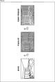
- FIG. 6 is a diagram illustrating a display example of danger information.
- the state shown at the left end of FIG. 6 is a normal state. Various information is displayed using the combination of the transmittance and the display luminance in FIG. In the example at the left end of FIG. 6, no information is displayed.
- the outline of the surrounding object is shown at the end of the white arrow # 2.
- Drawing for emphasis is performed.
- the display mode of the HMD 1 is switched from the display mode for normal time to the display mode for dangerous time, and information representing the outline of the peripheral object is displayed as the information for dangerous time instead of the information displayed so far.
- an image of a line representing the outline of each peripheral object such as a bed, a chair, a table, or a wall window is displayed superimposed on a dark landscape.
- An image of a line representing an outline including an edge or a pointed portion is displayed in a predetermined color.
- the HMD 1 not only detects the brightness of the surroundings, but also recognizes the surrounding objects by analyzing the image captured by the camera, and acquires information on the feature points that make up the outline of the surrounding objects It has been done repeatedly.
- Information on the feature points of the peripheral objects is repeatedly stored in the memory of the HMD 1 as environment information.
- the feature points of the peripheral objects include information on points at which the distance from the user changes abruptly, such as corners of stairs on the stairs.
- the HMD 1 repeatedly estimates the position and orientation of the user based on the information on the feature points of the surrounding objects, the acceleration detected by the acceleration sensor, the angular velocity detected by the gyro sensor, and the like. Has been done.
- FIG. 7 is a diagram showing a setting example of transmittance and display brightness used for displaying the information for danger.
- FIG. 7 The horizontal axis in Fig. 7 represents time.
- a in FIG. 7 represents a change in ambient illuminance
- B in FIG. 7 represents a change in transmittance
- C in FIG. 7 represents a change in display luminance of the display unit 11.
- the maximum transmittance is adjusted as shown in FIG. 7B. Moreover, the display of the information showing the outline of a peripheral object is started at the timing of time t1.
- the transmittance becomes the maximum transmittance after a predetermined time has elapsed from time t1.
- the state of maximum transmittance is continued for a predetermined time.
- the display brightness of the display unit 11 is set to the same display brightness as that before time t1 until time t2 immediately after time t1.
- the information representing the outline of the peripheral object is displayed using the same display brightness as the information displayed before that.
- the display brightness is adjusted so as to gradually decrease with the passage of time.
- FIG. 8 is a diagram showing an example of a change in display luminance.
- the horizontal axis represents time
- the vertical axis represents display luminance
- the display brightness of the display unit 11 gradually decreases after time t2 immediately after the display of information representing the outline of the surrounding object is started.
- a broken line L11 in FIG. 8 represents display luminance.
- the solid line L1 represents the user's dark adaptation characteristics.
- Dark adaptation is a change in vision in which visual acuity is gradually secured over time when the surrounding environment changes from a bright environment to a dark environment.
- the dark adaptation characteristic indicated by the solid line L1 represents a time change of the minimum brightness necessary for the user to visually recognize. At each time, the user can visually recognize information displayed at a display luminance higher than the luminance indicated by the solid line L1, and the user visually recognizes information displayed at a display luminance lower than the luminance indicated by the solid line L1. I can't.
- the display brightness used for displaying information representing the contour of the surrounding object gradually decreases, it is set as a value that is always visible to the user who has dark adaptation.
- the dark adaptation characteristics are set as, for example, general human characteristics. As will be described later, dark adaptation characteristics may be set according to user attributes such as age and visual acuity, and display luminance may be adjusted according to the set dark adaptation characteristics.
- the information representing the outline of the peripheral object is displayed while gradually decreasing the display brightness, it is possible to prevent the display of the information representing the outline of the peripheral object from impeding dark adaptation. For example, after a certain amount of time has elapsed, the user can immediately see the surrounding environment even if the HMD 1 is removed.
- FIG. 10 is a diagram illustrating an example of how the image is viewed when the HMD 1 is removed.
- FIG. 10 shows the appearance when the display luminance is not changed, and the lower part shows the appearance when the display luminance is changed as described with reference to FIG.
- the tip of the white arrow # 21 by suppressing the display brightness of the information representing the outline of the peripheral object in accordance with the dark adaptation characteristics, since the dark adaptation is not performed, the surrounding environment is changed. It becomes possible to prevent it from being difficult to see.
- the HMD 1 is removed, as indicated by the tip of the white arrow # 22, the user has been able to visually adjust the surrounding environment since dark adaptation has been achieved so far.
- the display brightness used for displaying information representing the outline of the peripheral object may be changed to a straight line (linear) instead of a curved line (non-linear) as shown in FIG. Further, it may be changed stepwise instead of continuously.
- FIG. 11 is a diagram showing an example of adjusting the color temperature.
- the color temperature is adjusted so as to gradually increase after time t2 immediately after the start of display of information representing the outline of the peripheral object.
- a broken line L21 in FIG. 11 represents the color temperature used by the display unit 11 for drawing.
- a solid line L1 represents the dark adaptation characteristics of the user.
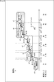
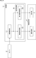
- FIG. 12 is a block diagram illustrating a configuration example of the HMD 1.
- the HMD 1 includes a control unit 51, a motion sensor 52, a camera 53, an illuminance sensor 54, a communication unit 55, a memory 56, and a video display unit 57.
- the motion sensor 52 includes an acceleration sensor 71 and a gyro sensor 72.
- the motion sensor 52, the camera 53, and the illuminance sensor 54 are not provided in the HMD 1, but may be provided in an external device such as a portable terminal held by the user.
- the control unit 51 includes a CPU (Central Processing Unit), ROM (Read Only Memory), RAM (Random Access Memory), and the like.
- the control unit 51 executes a program stored in the ROM or the memory 56 and controls the overall operation of the HMD 1.
- the position / posture estimation unit 81, the surrounding environment recognition unit 82, the imaging control unit 83, the display control unit 84, and the counter 85 are realized in the control unit 51.
- the position / posture estimation unit 81 estimates the state of the user based on the image captured by the camera 53, the acceleration detected by the acceleration sensor 71, and the angular velocity detected by the gyro sensor 72. For estimation of the user's state, information on the feature points of the surrounding objects recognized by the surrounding environment recognition unit 82 is also used as appropriate.
- the position / posture estimation unit 81 information related to peripheral objects at each position is prepared.
- the position / posture estimation unit 81 estimates the position of the user based on the peripheral object recognized by the peripheral environment recognition unit 82 and the peripheral object captured in the image captured by the camera 53.
- the position / posture estimation unit 81 is provided with information on acceleration and angular velocity for each posture of the user.
- the position / posture estimation unit 81 estimates the user's posture based on the acceleration detected by the acceleration sensor 71 and the angular velocity detected by the gyro sensor 72.
- the user state estimated by the position / posture estimation unit 81 includes at least one of the user position and the user posture.
- Information representing the position and orientation estimation results is supplied to the display control unit 84.
- the surrounding environment recognition unit 82 recognizes the position, shape, feature point, and the like of an actual object (peripheral object) in the vicinity by analyzing an image captured by the camera 53. As appropriate, the distance to the surrounding object, the height at which the surrounding object is placed, the type of the surrounding object, and the like are also recognized. Information for use in recognizing these contents is prepared for the surrounding environment recognition unit 82.
- the surrounding environment recognition unit 82 functions as an acquisition unit that acquires environment information that is information related to the surrounding physical environment.
- the surrounding environment recognition unit 82 outputs environment information including information on at least one of the position, shape, feature point, distance, height, and type of the surrounding object to the display control unit 84.
- the position of the peripheral object represents, for example, the relative position of the peripheral object based on the position of the HMD, and is acquired based on the captured image.
- a communication device such as a beacon may be installed in the surrounding object in advance, and the position may be acquired by the HMD based on a signal from the communication device.
- Information on the feature points of the peripheral objects included in the environment information output from the surrounding environment recognition unit 82 is also supplied to the position / posture estimation unit 81 and is used for estimating the position and posture of the user as appropriate.
- the imaging control unit 83 controls the camera 53 to repeatedly capture the landscape in front of the user's eyes.
- the imaging control unit 83 detects that the surrounding area has suddenly darkened based on the data supplied from the illuminance sensor 54, the imaging control unit 83 sets the imaging element of the camera 53 so as to increase the gain and lengthen the exposure time. Control. By changing the setting of the image sensor, it is possible to continue capturing an appropriate image used for recognition of the surrounding environment even when the periphery suddenly becomes dark.
- the display control unit 84 controls the display unit 11 and the light control element 14 of the video display unit 57 to display various types of information such as images and text.
- information indicating a combination of transmittance and display luminance as described with reference to FIG. 5 is prepared.
- the display by the display control unit 84 is performed based on data transmitted from an external device and received by the communication unit 55 or data read from the memory 56, for example.
- the display control unit 84 detects that the surrounding area has suddenly darkened based on the data supplied from the illuminance sensor 54, the display control unit 84 sets the display mode as the display mode for danger and displays the information for danger. Start.
- the display control unit 84 adjusts the display brightness or adjusts the color temperature with the passage of time represented by the count value supplied from the counter 85 after the display of the emergency information is started. Control the display of information for danger.
- the counter 85 outputs a count value indicating the passage of time to the display control unit 84.
- the acceleration sensor 71 of the motion sensor 52 detects the acceleration of the HMD 1 and outputs information on the detected acceleration to the position / posture estimation unit 81.
- the gyro sensor 72 detects the angular velocity of the HMD 1 and outputs information on the detected angular velocity to the position / posture estimation unit 81.
- the camera 53 is provided, for example, at a predetermined position in front of the HMD 1 and images a landscape in front of the user.
- the camera 53 outputs an image obtained by imaging to the position / posture estimation unit 81 and the surrounding environment recognition unit 82.
- the illuminance sensor 54 detects the illuminance and outputs illuminance information representing the brightness of the surroundings to the imaging control unit 83 and the display control unit 84.
- the communication unit 55 is a communication module such as a wireless LAN or Bluetooth (registered trademark).
- the communication unit 55 communicates with an external device such as a portable terminal held by the user or the content distribution server 2. Information presented to the user is acquired through communication by the communication unit 55.
- the memory 56 is a storage medium such as a flash memory.
- the memory 56 stores various data such as a program executed by the CPU of the control unit 51 and information presented to the user.
- the video display unit 57 includes the display unit 11 and the light control element 14.
- the video display unit 57 operates according to the control by the display control unit 84, and delivers video light of predetermined information together with external light to both eyes of the user via each unit of the right eye side optical system 1R and the left eye side optical system 1L.
- the HMD 1 is also provided with buttons operated by the user, a speaker that outputs sound, a microphone that detects the user's voice, and the like.
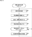
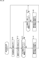
- step S1 display control processing is performed.
- the display control process performed in step S1 is a normal process with a small change in ambient brightness. Details of the display control process will be described later.
- the display control process displays predetermined information in the state described with reference to FIG.
- step S2 the surrounding environment recognition unit 82 recognizes the position, shape, feature point, and the like of the surrounding object by analyzing the image captured by the camera 53.
- the environmental information including the recognition result is supplied to the display control unit 84.
- step S ⁇ b> 3 the position / posture estimation unit 81 estimates the position and posture of the user based on the image captured by the camera 53, the acceleration detected by the acceleration sensor 71, and the angular velocity detected by the gyro sensor 72. To do. Information representing the position and orientation estimation results is supplied to the display control unit 84.
- step S4 the illuminance sensor 54 detects the ambient illuminance.
- Information representing the ambient illuminance is supplied to the display control unit 84.
- the peripheral environment recognition unit 82 repeatedly performs processing for recognizing the position, shape, feature points, and the like of the surrounding object, the position / posture estimation unit 81 for estimating the user's position and posture, and the illuminance sensor 54 for detecting ambient illuminance. Is called.
- step S5 the display control unit 84 determines whether or not the ambient illuminance has decreased by a certain level or more. If it is determined in step S5 that the ambient illuminance has fallen above a certain level, the process proceeds to step S6.
- step S6 a danger information display process is performed.
- the danger information display process is a process of terminating the display of the information displayed so far and displaying the danger information. Details of the danger time information display processing will be described later with reference to the flowchart of FIG.
- step S5 After the danger information display process is performed, or when it is determined in step S5 that the ambient illuminance has not decreased below a certain level, the process returns to step S1 and the above process is repeated.
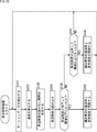
- step S11 the display control unit 84 controls the light control element 14 so that the transmittance is maximized.
- step S12 the display control unit 84 draws information representing the outline of the peripheral object recognized by the peripheral environment recognition unit 82.
- the image of the line representing the outline of the peripheral object is displayed at a position overlapping the actual outline of the peripheral object, for example, according to the position and posture of the user estimated by the position / posture estimation unit 81.
- step S13 the display control unit 84 determines whether or not a predetermined time has elapsed based on the count value measured by the counter 85.
- step S14 the display control unit 84 continues to draw information representing the contour by lowering the display brightness and increasing the color temperature.
- step S15 the display control unit 84 determines whether or not the ambient illuminance is equal to or higher than a certain level. Determine.
- step S15 If it is determined in step S15 that the ambient illuminance is not equal to or greater than a certain level, the process returns to step S12 and the display of the information representing the outline of the peripheral object is continued.
- step S15 When it is determined in step S15 that the ambient illuminance has become a certain level or more due to the elimination of the power failure, the process returns to step S6 in FIG. 13 and the subsequent processing is performed.
- information indicating the outline of the peripheral object is displayed as the information for danger, but the shape of the peripheral object such as information indicating the surface of the peripheral object and information indicating the feature point of the peripheral object is displayed.
- the line representing the outline of the peripheral object is also information indicating the shape of the peripheral object.
- the shape information that represents the shape of the surrounding object includes various color, shape, and pattern information such as a line that represents the outline of the surrounding object, a line and color that represents the surface of the surrounding object, and a mark that represents a feature point of the surrounding object. included.
- ⁇ Modification> Display example 1 for danger information Not only the contours of the surrounding objects in the real space, but also the information necessary in the event of danger is recognized in advance, but the information is displayed when the illuminance suddenly decreases. Good.
- Information necessary in the event of danger includes, for example, information such as exits of rooms, stairs, evacuation routes such as wide-area shelters, and places for flashlights.
- a method for recognizing information necessary in danger there is a method for performing object recognition based on an image captured by the camera 53.
- map information is given to the HMD 1 in advance, and information necessary at the time of danger is recognized according to a position measured by GPS (Global Positioning System).
- ⁇ Display example 2 for danger information In addition to the outline, information representing the shape of the entire peripheral object may be displayed. At this time, for example, the outline is highlighted. For highlighting, various methods are used such as changing the gradation, changing the display color, changing the thickness, blinking, and changing the line type to a broken line or a wavy line.
- contour highlighting may be performed by changing the display method according to the visibility information of the user. For example, when the user has low visibility of the color in the low wavelength region, the color in the high wavelength region is used for highlighting the outline.
- FIG. 15 is a diagram illustrating an example of highlight display of danger information.
- FIG. 15 is a state in which the outline of the peripheral object is displayed as it is.
- an image of a line representing the outline of a peripheral object is displayed superimposed on a dark landscape.
- the lines representing the contours of the surrounding objects are highlighted by the broken lines. Also good.
- an image of a line representing the outline of a low risk part such as a wall or a window may be hidden.
- lines representing the outline may be displayed in different colors according to the distance to the surrounding object.
- the line representing the outline of the bed at the closest position is displayed in the most prominent color
- the line indicating the outline of the chair and table at the next closest position is displayed in the next most prominent color.
- FIG. 16 is a diagram illustrating another example of highlighting information for danger.
- the state shown in the upper left of FIG. 16 is a state in which the outline of the peripheral object is displayed as it is.
- a line representing the outline of the surrounding object may be displayed with the gradation changed according to the degree of danger.
- the line representing the outline of the surrounding object may be displayed with the thickness changed according to the degree of danger.
- a line representing an outline but also corners and feature points may be highlighted.
- the highlighting of corners and feature points is performed using, for example, a conspicuous color, a conspicuous shape, blinking, or the like.
- a feature point is a part in which luminance and shape change greatly as compared with surrounding parts, and is specified by analyzing a captured image, for example.
- the line representing the outline is displayed by appropriately combining each element including the type, color, gradation, and thickness of the line.
- FIG. 17 is a diagram showing an example of setting the display brightness.
- FIG. 17A represents a change in ambient illuminance
- B in FIG. 17 represents luminance that is easily visible to the user.
- C in FIG. 17 represents display luminance.
- FIG. 17A when walking on a dark night road, as shown in FIG. 17A, when a headlight of a car traveling nearby gets into the eyes and becomes bright for a moment at time t11, it is shown in FIG. 17B.
- the luminance that is easy to visually recognize temporarily increases, and it becomes difficult to visually recognize the surroundings until dark adaptation is performed again.
- the display brightness of the contour of the peripheral object is once increased and controlled so as to gradually decrease, so that the contour of the peripheral object is not disturbed without disturbing the dark adaptation again. Can continue to be displayed.
- the danger information may be displayed at a timing other than when the surrounding brightness suddenly decreases.
- ⁇ Display example 6 for danger information There may be a case where the outline display of the peripheral object is not performed.
- a peripheral object at a position higher than the height of the user's back, such as a ceiling or lighting installed on the ceiling, is less likely to collide even if the user moves.
- a line representing the contour may not be displayed.
- ⁇ Dangerous information display example 7 When the intensity of outside light is low, it is considered that the moving speed of the user also decreases. By displaying a line representing an outline only for a nearby object in the vicinity without displaying a line representing an outline for a nearby object located far away, it is possible to reduce the danger during movement.
- the outline lines are not displayed, but only for peripherals such as bookshelves and shelves with casters that may move in the event of an earthquake.
- a line representing the outline may be displayed to call attention. Whether or not the position is likely to change is also specified based on the image captured by the camera 53 when the surrounding environment is recognized.
- Peripheral types include large / small size, high / low height, heavy / light weight, movable / fixed type, etc.
- the type of material is included.
- ⁇ Dangerous information display example 8 Information on a peripheral object that is not at a position where it can be displayed superimposed on the scenery in the real space may be displayed as danger information. For example, information on the direction of the evacuation route or fire based on information on peripheral objects that are outside the displayable range of the display unit 11 (the range of the frame F in FIG. 3) and within the imageable range of the camera 53. Information on the direction in which fire is sometimes emitted may be displayed. In addition, such information may be notified by voice using a speaker.
- ⁇ Display example 9 of danger information When the user can visually recognize the surrounding environment, only information that cannot be directly recognized, such as a route to a wide area evacuation site or information outside the user's field of view, may be displayed and the outline of the surrounding object may not be displayed. Information on the speed of dark adaptation and information on user attributes such as age and visual acuity are input in advance, and the information is used to determine whether the user can visually recognize the surrounding environment. Good.
- the acquisition of information on the peripheral object using the camera 53 may be stopped.
- the information on the peripheral object is updated by updating the information on the peripheral object acquired last by using the estimation result of the motion state of the user by the acceleration sensor 71 and the gyro sensor 72.
- information may be presented by combining information acquired based on an image captured by the camera 53 with an increased gain of the image sensor and information on acquired peripheral objects.
- information related to objects such as furniture hidden behind objects that cannot be recognized from an image captured by the camera 53 may be displayed.
- information related to objects such as furniture hidden behind objects that cannot be recognized from an image captured by the camera 53 may be displayed.
- Display example 10 of danger information Information related to peripheral objects that cannot be directly visually recognized by the user may be displayed as information for danger. For example, by displaying information on an object hidden behind a nearby object, it is possible to avoid hitting an object ahead of the object when a nearby object is stepped over or avoided.
- a risk level representing the degree of danger of the user in a dark environment may be calculated, and the display of the danger information may be controlled according to the calculated risk level.
- the degree of risk is obtained based on the user's state such as position and posture, and the surrounding environment represented by the environment information, for example.
- the information for danger may be displayed by changing the display color or gradation according to the place where the vertical movement such as stairs occurs or the degree of danger depending on the distance between the user and the surrounding object. Good. As a result, it is possible to urge the moving user to prevent tripping and to pay attention to nearby objects.
- FIG. 18 is a diagram showing an example of evaluation values used for risk assessment.
- the table shown in FIG. 18 shows evaluation values corresponding to the respective situations of “user posture”, “user moving speed”, “periphery of surrounding objects”, and “user position (distance to surrounding objects)”. It is a table
- the evaluation value is expressed in three stages of “0”, “1”, and “2”, and the higher the numerical value, the higher the risk level.
- “User's moving speed” As shown in the evaluation value of “User's moving speed”, when the user is moving at a speed of less than 1 km / h, “0” is set as the evaluation value, and it is 1 km / h or more and 3 km / h or less. When moving at a speed, “1” is set as the evaluation value. When the user is moving at a speed exceeding 3 km / h, “2” is set as the evaluation value.
- 0 is set as the evaluation value when the unevenness of the peripheral object is less than 10 cm
- “1” is set as the evaluation value when it is 10 cm or more Is done.
- the evaluation value As shown as an evaluation value of “user position”, when the distance to the surrounding object exceeds 2 m, the evaluation value is set as “0”, and when the distance is 1 m or more and 2 m or less, the evaluation value is “ 1 "is set. When the distance to the surrounding object is less than 1 m, “2” is set as the evaluation value.
- evaluation values used for risk assessment are set according to each situation.
- the risk of each peripheral object is obtained as, for example, the sum of evaluation values. For example, if a user is moving at a speed of 1 km / h or more and 3 km / h or less, and a peripheral object having a surface with an unevenness of 10 cm or more is at a distance of 1 m or more and 2 m or less, the risk of the peripheral object is Required as “5”.
- FIG. 19 is a diagram showing a display example according to the degree of risk.
- the items of the display method of the information representing the outline of the surrounding object include line type, blinking / non-flashing of line, gradation, color, thickness, presence / absence of feature point display, and feature.
- the presence / absence of blinking dots is shown.
- the line type is set as a solid line, and the presence / absence of blinking of the line is set as none.
- the gradation is set as half of the maximum value, and the color is set as green.
- the thickness is set as 1 pix (1 pixel), and the presence / absence of feature point display is set as no.
- the presence / absence of blinking feature points is set as none.
- Example of output of danger information In addition to detecting a sudden decrease in illuminance, the detection of a siren's sound with a microphone or the detection of a fire with a temperature sensor can be used as a trigger. Information may be displayed. The occurrence of a disaster may be detected based on information transmitted from an external device, and danger information may be displayed using this as a trigger.
- the display of the information for danger may be terminated on the assumption that the user has returned to the situation where the surrounding environment can be visually recognized.
- the display of the danger information may be stopped at the timing when it is detected that the user has removed the HMD 1 by the mounting detection proximity sensor mounted on the HMD 1.
- the display of the information for danger may be stopped at the timing instructed by the user or the timing at which the arrival of the user at the wide-area refuge is detected based on the position information measured by GPS.
- ⁇ Information on the user's age may be set in advance.
- the display luminance reduction rate is adjusted according to the dark adaptation characteristics according to the age of the user.
- the dark adaptation characteristics may be set not only according to the age but also according to various user attributes such as visual acuity and sex, and the display luminance may be adjusted according to the set dark adaptation characteristics.
- the display brightness may be adjusted according to the characteristics according to the user's state such that the characteristics are switched between when the user is stationary and when the user is moving.
- Example of environment recognition Although the surrounding environment is recognized based on the image captured by the camera 53, the surrounding environment may be recognized using another sensor.
- the surrounding environment may be recognized using a ToF (Time-of-Flight) sensor using infrared rays.
- ToF Time-of-Flight
- the ToF sensor it is possible to recognize the surrounding environment even in a dark environment that cannot be recognized by the camera 53 equipped with an imaging device capable of detecting visible light.
- the environmental information showing the surrounding environment was acquired based on the image imaged with the camera, you may make it acquire from the server connected via a network.
- the model number information of a sofa that exists as a peripheral object is acquired, information on the shape of the sofa may be acquired from the server based on the model number information.
- the model number information of the sofa may be acquired by communicating with a device built in the sofa, for example, or may be specified based on the position information of the HMD 1.
- FIG. 20 is a diagram illustrating a setting example of transmittance and display luminance.
- the combination of the transmittance and display luminance shown in FIG. 20 is the same as the combination described with reference to FIG.
- the horizontal axis in FIG. 20 represents the brightness of the surroundings, and the vertical axis represents the visibility of the display content.
- the ambient brightness is represented by luminance or illuminance.
- the transmittance is set in three stages of 10%, 20%, and 50%.
- the display luminance used in combination with the transmittance is set in five stages of 40%, 50%, 60%, 80%, and 100%.
- the transmittance is adjusted with a smaller number of steps than the number of steps of display luminance.
- the state s1 is a state in which a combination in which the transmittance is 50% and the display luminance is 50% is used.
- the states s2 to s4 are states in which a combination is used in which the transmittance is 20% and the display luminance is 40%, 60%, and 80%, respectively. Since a lower transmittance is set than in the state s1, the external light reaching the user's eyes is further suppressed in the states s2 to s4.
- the states s5 to s7 are states in which a combination of 10% transmittance and 60%, 80%, and 100% display luminance is used, respectively. Since a lower transmittance is set than in the states s2 to s4, the external light reaching the user's eyes is further suppressed in the states s5 to s7.
- the display brightness is adjusted by adjusting the duty ratio of a pulse representing the display period of the display unit 11 (display device 21).
- the display control unit 84 in FIG. 12 adjusts the display luminance of the display unit 11 by outputting a control signal including a pulse having a predetermined duty ratio.
- the duty ratio of the pulses constituting the control signal corresponds to the display brightness of the display unit 11.
- the duty ratio is also lower than the previous duty ratio, that is, the display brightness is set to be dark. This is because when the transmittance decreases by one step, the external light limited by the light control element 14 is further limited, and the amount of light incident on the user's eyes is reduced, so that the display brightness of the image is preferably lowered. Because. By performing such control, deterioration of the display device 21 can be suppressed.
- the transition from the state s1 to the state s2 occurs when the surrounding brightness changes to the brightness n12 when the brightness is lower than the brightness n12.
- the transition from the state s2 to the state s1 indicated by an arrow # 111 occurs when the surrounding brightness changes to the brightness n11 when the brightness is higher than the brightness n11.
- the brightness n12 at which the transition from the state s1 to the state s2 occurs is set as a value brighter than the brightness n11 at which the transition from the state s2 to the state s1 occurs.
- the transition from the state s2 to the state s3 occurs when the ambient brightness changes to the brightness n14 in a state where the brightness is lower than the brightness n14.
- the transition from the state s3 to the state s2 indicated by the arrow # 112 occurs when the surrounding brightness changes to the brightness n13 in a state where the brightness is brighter than the brightness n13.
- the brightness n14 at which the transition from the state s2 to the state s3 occurs is set as a brighter value than the brightness n13 at which the transition from the state s3 to the state s2 occurs.
- transitions between other states For example, as indicated by an arrow # 106, the transition from the state s6 to the state s7 occurs when the surrounding brightness changes to the brightness n22 in a state where the brightness is lower than the brightness n22. On the other hand, the transition from the state s7 to the state s6, indicated by the arrow # 116, occurs when the surrounding brightness is changed to the brightness n21 in a state where the brightness is brighter than the brightness n21.
- the brightness n22 at which the transition from the state s6 to the state s7 occurs is set as a brighter value than the brightness n21 at which the transition from the state s7 to the state s6 occurs.
- the hysteresis characteristic is set for adjusting the transmittance as shown by the bidirectional arrows in FIG.
- the threshold for increasing the transmittance when changing from a bright state to a dark state and the threshold for decreasing the transmittance when changing from a dark state to a bright state the transmittance is frequently increased. Can be prevented from changing.
- ⁇ Hysteresis characteristics are set not only for transmittance adjustment but also for display brightness adjustment. As a result, the display luminance can be adjusted in a more natural manner in accordance with the change in external light.
- FIG. 21 is another diagram showing a setting example of transmittance and display luminance.
- the upper part of FIG. 21 shows the change in transmittance when the horizontal axis is the brightness of the surroundings and the vertical axis is the transmittance.
- the transmittance referred to here is the transmittance of the entire HMD 1 realized by adjusting the transmittance of the light control element 14.
- the lower part of FIG. 21 represents a change in display luminance when the horizontal axis is the peripheral brightness and the vertical axis is the display luminance of the display unit 11.
- the transmittance changes from 50% to 20% when the brightness is n12, and 20% when the brightness is n18. To 10%. Further, when the periphery changes from a bright state to a dark state, the transmittance changes from 10% to 20% when the brightness is n17, and from 20% to 50% when the brightness is n11.
- the display luminance changes from 50% to 40% at the brightness n12 and 40% at the brightness n14.
- the display brightness changes from 60% to 80% when the brightness is n16, and changes from 80% to 60% when the brightness is n18.
- the display luminance changes from 60% to 80% when the brightness is n20, and changes from 80% to 100% when the brightness is n22.
- the display luminance changes from 100% to 80% when the brightness is n21, and changes from 80% to 60% when the brightness is n19.
- the display brightness changes from 60% to 80% when the brightness is n17, and changes from 80% to 60% when the brightness is n15.
- the display brightness changes from 60% to 40% when the brightness is n13, and changes from 40% to 50% when the brightness is n11.
- the HMD 1 displays various types of information using such a combination of transmittance and display luminance.
- Control of the transmittance and display brightness according to the surrounding brightness is performed at intervals according to the user's state, such as the speed at which the user is moving.
- Japanese Patent Application Laid-Open Nos. 2012-252091 and 2013-5201 disclose techniques for controlling the transmittance based on the output value of the illuminance sensor.
- an electrochromic element may be used as the light control element.
- the electrochromic element changes the transmittance by utilizing an oxidation reaction / reduction reaction of a material.
- the light control device using a chemical reaction such as ion diffusion has a slow response speed of a change in transmittance of several seconds compared to a device such as a liquid crystal shutter. Due to the slow response speed, when moving from a bright place to a dark place, a situation may occur in which the increase in transmittance is delayed and the user's field of vision remains dark for a few seconds.
- Measures such as shortening the brightness detection cycle can be considered as a countermeasure against the slow response speed.
- the transmittance changes in conjunction with a short-time change in brightness. The transmittance changes frequently, and the user may feel uncomfortable.
- the light control element respond quickly when a change in brightness occurs, but if the change in transmittance occurs too frequently, the user may feel uncomfortable.
- various processes such as controlling the transmittance and the display brightness at intervals according to the user's state are performed in order to prevent the user from feeling uncomfortable.
- FIG. 22 is a block diagram illustrating a configuration example of the HMD 1.
- FIG. 22 shows only a part of the configuration of the HMD 1.
- the HMD 1 in FIG. 22 includes other configurations described with reference to FIG. The same applies to the configurations shown in FIGS. 24, 26, and 28.
- the 22 includes a position / attitude estimation unit 81 and a display control unit 84.
- the display control unit 84 includes a transmittance control unit 101 and a display luminance control unit 102.
- the position / posture estimation unit 81 analyzes the sensor data supplied from the motion sensor 52 and estimates the state of the user.
- the user state estimated by the position / posture estimation unit 81 includes at least one of the type of user movement and the speed of the user movement.
- Information on the acceleration detected by the acceleration sensor 71 constituting the motion sensor 52 and the angular velocity detected by the gyro sensor 72 are supplied to the position / orientation estimation unit 81 as sensor data.
- classification of types of movement such as a situation in which a movement such as a head swing does not occur with a change in brightness and a situation in which the HMD 1 is moving without moving is performed based on a change in acceleration.
- the speed of the user's movement is detected by the integrated value of acceleration.
- a geomagnetic sensor may be provided in the motion sensor 52, and the speed of the user's movement may be detected based on information on the direction.
- the position / posture estimation unit 81 outputs information indicating the type of user movement and the speed of the user movement to the transmittance control unit 101 and the display luminance control unit 102.
- the transmittance control unit 101 identifies the state of the user based on the information supplied from the position / posture estimation unit 81 and adjusts the reading interval of the ambient illuminance detected by the illuminance sensor 54.
- the detection of ambient illuminance by the illuminance sensor 54 is repeatedly performed at a predetermined cycle.
- the transmittance control unit 101 reads the ambient illuminance according to the adjusted readout interval, and controls the transmittance of the light control element 14 as described with reference to FIG. By controlling the reading interval of the peripheral illuminance, the interval for controlling the transmittance of the light control element 14 is also controlled.
- the transmittance control unit 101 reads the ambient illuminance at long intervals such as 1 second or more.
- the transmittance control unit 101 does not need to shorten the interval for controlling the transmittance so much.
- the transmittance of the light control element 14 is not controlled, so that the user is uncomfortable. Can be prevented.
- the transmittance control unit 101 reads the ambient illuminance at short intervals such as 0.1 seconds.
- the transmittance control unit 101 sets the reading interval of the peripheral illuminance short.
- the display brightness control unit 102 controls the peripheral illuminance readout interval and the display brightness control interval in the same manner as the transmittance control unit 101.
- the display luminance control unit 102 specifies the user state based on the information supplied from the position / posture estimation unit 81 and adjusts the reading interval of the ambient illuminance.
- the display luminance control unit 102 reads the peripheral illuminance according to the adjusted reading interval, and controls the display luminance of the display unit 11 as described with reference to FIG.
- the display brightness control unit 102 reads the ambient illuminance at long intervals such as 1 second or more.
- the display luminance control unit 102 reads the ambient illuminance at short intervals such as 0.1 seconds.
- step S101 the acceleration sensor 71 of the motion sensor 52 detects the acceleration of the HMD1, and the gyro sensor 72 detects the angular velocity of the HMD1.
- the acceleration information and the angular velocity information are supplied to the position / posture estimation unit 81 as motion data.
- step S102 the position / orientation estimation unit 81 analyzes the motion data supplied from the motion sensor 52, estimates the type of the user's movement, and calculates the speed of the user's movement. Information indicating the type of user movement and the speed of the user movement is supplied to the transmittance control unit 101 and the display luminance control unit 102.
- step S ⁇ b> 103 the display control unit 84 (the transmittance control unit 101 and the display luminance control unit 102) specifies the user state based on the information supplied from the position / posture estimation unit 81, and the surroundings detected by the illuminance sensor 54. Determine the illuminance readout interval.
- step S104 the display control unit 84 reads the ambient illuminance according to the determined reading interval.
- step S105 the display control unit 84 determines whether or not the ambient illuminance has decreased to be equal to or less than a threshold value.
- step S106 the display control unit 84 controls the transmittance and the display luminance. That is, the transmittance of the dimming element 14 is adjusted by the transmittance control unit 101 using the combination when the ambient illuminance is lower than the threshold value described with reference to FIGS. 20 and 21, and the display luminance control unit 102. Thus, the display brightness of the display unit 11 is adjusted.
- step S107 the display control unit 84 determines whether or not the ambient illuminance has increased to be greater than or equal to the threshold.
- step S108 the display control unit 84 controls the transmittance and the display luminance.
- the transmittance of the dimming element 14 is adjusted by the transmittance control unit 101 using the combination when the ambient illuminance rises above the threshold value described with reference to FIGS. 20 and 21, and the display luminance control unit 102.
- the display brightness of the display unit 11 is adjusted.
- step S107 When it is determined in step S107 that the ambient illuminance is not equal to or greater than the threshold value, or after the processing in steps S106 and S108 is performed, the process returns to step S101 and the above processing is repeated.
- the transmittance and the transmission rate are not delayed.
- the display brightness can be adjusted.
- the user's safety during walking can be ensured by adjusting the transmittance and display brightness without delay.
- the transmittance and display brightness do not change frequently, so there is no response to changes in brightness for a short time, and the occurrence of unpleasant changes in transmittance and display brightness can be suppressed. it can. Further, by increasing the interval for controlling the transmittance and the display luminance, it is possible to reduce the calculation resources, and it is possible to reduce the power consumption and distribute the resources for image rendering.
- step S1 of FIG. Such display control processing is performed in step S1 of FIG. Similarly, the display control process described with reference to FIGS. 25, 27, and 29 is the process performed in step S1 of FIG.
- the detection interval of the peripheral illuminance by the illuminance sensor 54 may be adjusted.
- FIG. 24 is a block diagram illustrating another configuration example of the HMD 1.
- the configuration of the control unit 51 of the HMD 1 shown in FIG. 24 is different from the configuration shown in FIG. 22 in that an image analysis unit 111 is provided instead of the position / posture estimation unit 81.
- the image taken by the camera 53 is supplied to the image analysis unit 111. Imaging by the camera 53 is repeatedly performed at a predetermined cycle.
- the brightness after a predetermined time elapses is predicted by analyzing the image captured by the camera 53, and the transmittance and display luminance are controlled according to the predicted change in brightness.
- the image analysis unit 111 detects a change in brightness by comparing the central luminance of the current image with the central luminance of the image captured immediately before.
- the center luminance is a luminance within a predetermined range including the center of the image.
- a change in brightness may be detected using the brightness of the entire image.
- the luminance at the center of the image represents the luminance of the entire image after a predetermined time.
- the image analysis unit 111 calculates the central luminance, which is the luminance of the image central portion, as the luminance representing the brightness after a lapse of a predetermined time, with the direction of the image central portion being the user moving direction.
- the image analysis unit 111 outputs the central luminance information to the transmittance control unit 101 and the display luminance control unit 102.
- the transmittance control unit 101 controls the transmittance of the light control element 14 as described with reference to FIG. 20 and the like based on the central luminance represented by the information supplied from the image analysis unit 111. By performing processing in accordance with the central luminance, the transmittance is controlled in a proactive manner.
- the display luminance control unit 102 controls the display luminance of the display unit 11 based on the central luminance represented by the information supplied from the image analysis unit 111 as described with reference to FIG. By performing processing according to the center luminance, the display luminance of the display unit 11 is controlled in advance.
- step S111 the camera 53 images the surrounding environment.
- step S112 the image analysis unit 111 calculates the center luminance of the image captured by the camera 53.
- step S113 the display control unit 84 determines whether or not the central luminance has decreased to be equal to or lower than the threshold value.
- step S114 the display control unit 84 controls the transmittance and the display luminance.
- the transmittance of the dimming element 14 is adjusted by the transmittance control unit 101 using the combination when the luminance is lower than the threshold value described with reference to FIGS. 20 and 21, and the display unit is controlled by the display luminance control unit 102. 11 display brightness is adjusted.
- step S115 the display control unit 84 determines whether the central luminance has increased and has become equal to or greater than the threshold value.
- step S116 the display control unit 84 controls the transmittance and the display luminance.
- the transmittance of the dimming element 14 is adjusted by the transmittance control unit 101 using the combination when the luminance has risen above the threshold value described with reference to FIGS. 20 and 21, and the display unit is controlled by the display luminance control unit 102. 11 display brightness is adjusted.
- step S115 When it is determined in step S115 that the central luminance is not equal to or greater than the threshold value, or after the processing in steps S114 and S116 is performed, the process returns to step S111 and the above processing is repeated.
- the transmittance and display brightness can be adjusted without delay by predicting the brightness of the environment in which the user is assumed to be after a predetermined time based on the image captured by the camera 53. Is possible.
- FIG. 26 is a block diagram illustrating still another configuration example of the HMD 1.
- the configuration of the control unit 51 of the HMD 1 shown in FIG. 26 is different from the configuration shown in FIG. 24 in that a position / posture estimation unit 81 and an imaging control unit 83 are provided.
- the imaging interval by the camera 53 is adjusted according to the state of the user.
- the brightness of the surroundings is predicted from the image captured by the camera 53, and the transmittance and display luminance are controlled in accordance with the predicted change in brightness.
- the position / orientation estimation unit 81 analyzes the sensor data supplied from the motion sensor 52 and detects the type of user movement and the speed of the user movement.
- the position / posture estimation unit 81 outputs information indicating the type of user movement and the speed of the user movement to the imaging control unit 83.
- the imaging control unit 83 identifies the user state based on the information supplied from the position / posture estimation unit 81 and adjusts the imaging interval of the camera 53.
- the imaging control unit 83 performs surrounding imaging at a long interval such as 1 second or more.
- the transmittance control unit 101 captures surrounding images at short intervals such as 0.1 seconds. An image captured by the camera 53 according to the adjusted interval is supplied to the image analysis unit 111.
- the image analysis unit 111 detects a change in brightness based on the center luminance of the image captured by the camera 53, similarly to the image analysis unit 111 in FIG.
- step S121 the acceleration sensor 71 of the motion sensor 52 detects the acceleration of the HMD1, and the gyro sensor 72 detects the angular velocity of the HMD1.
- the acceleration information and the angular velocity information are supplied to the position / posture estimation unit 81 as motion data.
- step S122 the position / orientation estimation unit 81 analyzes the motion data supplied from the motion sensor 52, estimates the type of the user's movement, and calculates the speed of the user's movement. Information representing the type of user movement and the speed of the user movement is supplied to the imaging control unit 83.
- step S123 the imaging control unit 83 identifies the user's state based on the information supplied from the position / posture estimation unit 81, and determines the imaging interval of the camera 53.
- step S124 the camera 53 images the surrounding environment according to the imaging interval determined by the imaging control unit 83.
- step S125 the image analysis unit 111 calculates the center luminance of the image captured by the camera 53.
- step S126 the image analysis unit 111 determines whether or not the center luminance has decreased by ⁇ L from the luminance d seconds before, which is a preset time.
- ⁇ L represents a predetermined luminance.
- step S127 the image analysis unit 111 predicts the brightness of the entire image after T seconds based on the current user speed. For example, a range corresponding to the current user speed is set in the image captured by the camera 53, and the luminance of the set range is obtained as the predicted luminance of the entire image after T seconds.
- step S1208 the image analysis unit 111 determines whether the predicted luminance is equal to or less than a threshold value.
- step S129 the display control unit 84 controls the transmittance and the display brightness.
- the transmittance of the dimming element 14 is adjusted by the transmittance control unit 101 using the combination when the luminance is lower than the threshold value described with reference to FIGS. 20 and 21, and the display unit is controlled by the display luminance control unit 102. 11 display brightness is adjusted.
- step S130 the image analysis unit 111 has increased the central luminance by ⁇ L from the luminance before d seconds. It is determined whether or not.
- step S131 the image analysis unit 111 predicts the luminance of the entire image after T seconds based on the current user speed.
- step S132 the image analysis unit 111 determines whether the predicted luminance is equal to or higher than a threshold value.
- step S133 the display control unit 84 controls the transmittance and the display luminance.
- the transmittance of the dimming element 14 is adjusted by the transmittance control unit 101 using the combination when the luminance has risen above the threshold value described with reference to FIGS. 20 and 21, and the display unit is controlled by the display luminance control unit 102. 11 display brightness is adjusted.
- step S132 If it is determined in step S132 that the predicted luminance is not greater than or equal to the threshold value, the process returns to step S121 and the above processing is repeated.
- step S130 When it is determined in step S130 that the luminance has not increased by ⁇ L from the luminance d seconds before, or when the processing in steps S129 and S133 is performed, the processing returns to step S121 and the above processing is repeated.
- the setting of T seconds may be switched between when the user is walking and when the user is running. For example, when the user is running, the brightness of the previous time is predicted for a shorter time than when walking.
- FIG. 28 is a block diagram showing still another configuration example of the HMD 1.
- the configuration of the control unit 51 of the HMD 1 illustrated in FIG. 28 is different from the configuration illustrated in FIG. 26 in that a surrounding environment recognition unit 82 and a location information processing unit 121 are provided instead of the imaging control unit 83.
- the brightness of the surroundings after a predetermined time has been predicted based on the location information, and the transmittance and display luminance are controlled according to the predicted change in brightness.
- the location information is user location information.
- the position / orientation estimation unit 81 analyzes the sensor data supplied from the motion sensor 52 and detects the type of user movement and the speed of the user movement.
- the position / posture estimation unit 81 outputs information representing the type of user movement and the speed of the user movement to the image analysis unit 111 and the location information processing unit 121.
- the image analysis unit 111 analyzes the image captured by the camera 53 in response to the detection of the type of user motion and the speed of the user motion by the position / posture estimation unit 81, and the image is captured in the image. Extract features of surrounding environment.
- the image analysis unit 111 outputs information related to characteristics of the surrounding environment to the location information processing unit 121.
- the surrounding environmental features extracted by the image analysis unit 111 are used for estimation of the current position.
- the location information processing unit 121 estimates the current position based on the feature represented by the information supplied from the image analysis unit 111. For the location information processing unit 121, for example, information on the feature of each position on the map is given in advance together with the map information.
- the location information processing unit 121 estimates the current position by comparing the feature represented by the information supplied from the image analysis unit 111 with the feature of each position given in advance.
- the current position is estimated by appropriately correcting the position according to the user's state detected by the position / posture estimation unit 81.
- the location information processing unit 121 estimates a position after a predetermined time has elapsed from the current position according to the state of the user detected by the position / posture estimation unit 81, and displays information indicating the estimation result together with the current position information. Output to the surrounding environment recognition unit 82.
- the surrounding environment recognition unit 82 specifies the surrounding illuminance detected by the illuminance sensor 54 as the surrounding illuminance at the current position.
- the surrounding environment recognition unit 82 estimates the surrounding illuminance at a position after a predetermined time, which is represented by the information supplied from the location information processing unit 121. For example, information related to ambient illuminance at each position on the map is given in advance to the surrounding environment recognition unit 82 together with the map information.
- the surrounding environment recognizing unit 82 refers to information on the surrounding illuminance at each position given in advance, and identifies the surrounding illuminance at the position estimated by the location information processing unit 121. For example, the ambient environment recognition unit 82 predicts the ambient illuminance at a position T seconds after the current time.
- step S141 the acceleration sensor 71 of the motion sensor 52 detects the acceleration of the HMD1, and the gyro sensor 72 detects the angular velocity of the HMD1.
- the acceleration information and the angular velocity information are supplied to the position / posture estimation unit 81 as motion data.
- step S142 the position / orientation estimation unit 81 analyzes the motion data supplied from the motion sensor 52, estimates the type of user movement, and calculates the speed of the user movement. Information on the type of user movement and the speed of user movement is supplied to the image analysis unit 111 and the location information processing unit 121.
- step S143 the camera 53 images the surrounding environment.
- the captured image is supplied to the image analysis unit 111.
- step S144 the image analysis unit 111 analyzes the image captured by the camera 53, and extracts features of the surrounding environment that are reflected in the image. Information regarding the characteristics of the surrounding environment is supplied to the location information processing unit 121.
- step S145 the location information processing unit 121 estimates the current position based on the feature represented by the information supplied from the image analysis unit 111.
- step S146 the surrounding environment recognition unit 82 acquires the surrounding illuminance at the current position detected by the illuminance sensor 54.
- step S147 the surrounding environment recognition unit 82 determines whether or not the surrounding illuminance has decreased by a certain level or more.
- step S147 when it is determined in step S147 that the ambient illuminance has decreased more than a certain value because the ambient illuminance has suddenly decreased, the danger information display process described with reference to FIG. 14 is performed in step S148.
- step S147 If it is determined in step S147 that the ambient illuminance has not decreased by a certain value or more, or if a danger information display process is performed in step S148, the process proceeds to step S149.
- step S149 the surrounding environment recognition unit 82 predicts the surrounding illuminance at the position after T seconds based on the current user speed.
- step S150 the surrounding environment recognition unit 82 determines whether or not the surrounding illuminance at the position after T seconds decreases and becomes equal to or less than the threshold value.
- step S151 the display control unit 84 controls the transmittance and the display luminance.
- the transmittance of the dimming element 14 is adjusted by the transmittance control unit 101 using the combination when the ambient illuminance decreases below the threshold value described with reference to FIGS. 20 and 21, and displayed by the display luminance control unit 102.
- the display brightness of the unit 11 is adjusted.
- step S150 if it is determined in step S150 that the ambient illuminance at the position after T seconds does not become the threshold or less, the ambient environment recognition unit 82 increases the ambient illuminance at the position after T seconds and exceeds the threshold in step S152. It is determined whether or not.
- step S153 the display control unit 84 controls the transmittance and the display luminance.
- the transmittance of the dimming element 14 is adjusted by the transmittance control unit 101 using the combination when the ambient illuminance rises above the threshold value described with reference to FIGS.
- the display brightness of the unit 11 is adjusted.
- step S152 If it is determined in step S152 that the ambient illuminance after T seconds does not exceed the threshold, the process returns to step S141 and the above processing is repeated. Similarly, when the processes of steps S151 and S153 are performed, the process returns to step S141 and the above processes are repeated.
- the ambient illuminance at the position where the user is estimated to be present after a predetermined time has passed is predicted, and the transmittance and display are displayed without delay with respect to changes in the ambient illuminance.
- the brightness can be adjusted.
- the current position is estimated by analyzing the image
- the current position may be estimated using GPS or the like.
- the control unit 51 can predict a sudden change in illuminance near the entrance and exit of the tunnel and change the transmittance and the display luminance in advance.
- Measures regarding the accuracy of positioning results are required when using GPS. For example, when there is a certain difference between the speed obtained from the transition of the GPS measurement result and the speed calculated based on the sensor data detected by the motion sensor 52, the sensor data detected by the motion sensor 52 The positioning result may be corrected based on the calculated speed.
- the above display control can be applied not to glasses-type wearable terminals but to mobile terminals such as smart phones and tablet terminals.
- the transparency of the image captured by the camera is adjusted in the same manner as the transmittance of the light control element 14 and displayed in an overlapping manner.
- the display brightness of the image is adjusted in the same manner as the display brightness of the display unit 11.
- control unit for controlling display and the display unit (video display unit 57) are provided inside the HMD 1, they may be provided outside the HMD 1.
- control performed by the display control unit includes not only direct control of the light control element and the display unit but also output of a control signal for display to the display unit.
- the control signal may be image data itself to be displayed, or may be only a signal for instructing image display.
- FIG. 30 is a block diagram showing an example of the hardware configuration of a computer that executes the above-described series of processing by a program.
- a CPU Central Processing Unit
- ROM Read Only Memory
- RAM Random Access Memory
- an input / output interface 1005 is connected to the bus 1004.
- the input / output interface 1005 is connected to an input unit 1006 including a keyboard and a mouse, and an output unit 1007 including a display and a speaker.
- the input / output interface 1005 is connected to a storage unit 1008 made up of a hard disk, a non-volatile memory, etc., a communication unit 1009 made up of a network interface, etc., and a drive 1010 that drives a removable medium 1011.
- the CPU 1001 loads the program stored in the storage unit 1008 to the RAM 1003 via the input / output interface 1005 and the bus 1004 and executes it, thereby executing the above-described series of processing. Is done.
- the program executed by the CPU 1001 is recorded in the removable medium 1011 or provided via a wired or wireless transmission medium such as a local area network, the Internet, or digital broadcasting, and installed in the storage unit 1008.
- a wired or wireless transmission medium such as a local area network, the Internet, or digital broadcasting
- the program executed by the computer may be a program that is processed in time series in the order described in this specification, or in parallel or at a necessary timing such as when a call is made. It may be a program for processing.
- the system means a set of a plurality of components (devices, modules (parts), etc.), and it does not matter whether all the components are in the same housing. Accordingly, a plurality of devices housed in separate housings and connected via a network and a single device housing a plurality of modules in one housing are all systems. .
- Embodiments of the present technology are not limited to the above-described embodiments, and various modifications can be made without departing from the gist of the present technology.
- the present technology can take a cloud computing configuration in which one function is shared by a plurality of devices via a network and is jointly processed.
- each step described in the above flowchart can be executed by one device or can be shared by a plurality of devices.
- the plurality of processes included in the one step can be executed by being shared by a plurality of apparatuses in addition to being executed by one apparatus.
- An acquisition unit that acquires environment information that is information about an environment including an object that exists in real space; When a change greater than a threshold value occurs in the brightness of the real space, the shape information representing the shape of the object is displayed on a display unit that displays predetermined information in a state of being visible while being superimposed on the real space.
- An information processing apparatus comprising: a display control unit that performs display control based on environmental information.
- the display control unit controls a change in luminance of the shape information according to a user attribute or according to a user state including at least one of the user position and posture.
- the information processing apparatus can display an outline of the object as the shape information.
- the acquisition unit acquires information on at least one of the position of the object, the distance to the object, the height of the object, and the type of the object as the environment information. (1) to (4) ).
- the display control unit controls display of the shape information in accordance with a risk level of the object specified based on the environment information.
- the display control unit displays the outline of the object as the shape information by changing at least one of type, thickness, color, and gradation according to the degree of risk.
- the information processing apparatus according to any one of (6).
- the information processing apparatus displays information representing a feature point of the object as the shape information.
- the information processing apparatus controls the dimming unit to increase a transmittance when a change in brightness greater than the threshold value occurs.
- the information processing apparatus is a head-mounted display attached to a head of the user.
- An imaging unit for imaging the real space The imaging control unit according to any one of (1) to (10), further including: an imaging control unit that controls the imaging unit so as to increase a gain and lengthen an exposure time when a brightness change greater than the threshold occurs.
- Information processing device (12) The information processing apparatus according to any one of (1) to (11), wherein the display control unit displays the shape information by gradually increasing a color temperature after displaying the shape information. (13) The display control unit displays the shape information instead of the information displayed before the brightness change occurs when the brightness change is greater than the threshold value. (1) to (12) The information processing apparatus according to any one of the above.
- the information processing apparatus according to any one of (1) to (13), wherein the display control unit ends the display of the shape information when the brightness of the real space becomes a predetermined brightness.
- Information processing device Obtain environment information, which is information about the environment including objects that exist in real space, When a change greater than a threshold value occurs in the brightness of the real space, the shape information representing the shape of the object is displayed on a display unit that displays predetermined information in a state of being visible while being superimposed on the real space.
- An information processing method that performs display control based on environmental information.
- this technique can also take the following structures.
- a dimmer that guides light in real space to the user's eyes with a predetermined transmittance;
- a display unit that displays predetermined information in a state of being visible in a superimposed manner in the real space;
- a display control unit that controls the transmittance of the light control unit and the brightness of the predetermined information displayed by the display unit according to the brightness of the real space at intervals according to the state of the user
- An information processing apparatus comprising: (B) The said display control part controls the transmittance
- Information processing device is a space
- (C) The information processing apparatus according to (A) or (B), wherein, when the user is moving, the display control unit adjusts the interval so as to be shorter as the moving speed of the user is faster.
- (D) The information processing apparatus according to any one of (A) to (C), wherein the display control unit controls the transmittance of the dimming unit and the luminance of the predetermined information according to a preset combination.
- (E) The information processing apparatus according to (D), wherein the display control unit adjusts the transmittance of the dimming unit with a number of steps smaller than a number of steps used for switching the luminance of the predetermined information.
- the predetermined combination is used using the second combination that is used when the brightness of the real space is brighter.
- the brightness of the real space that becomes a threshold when transitioning to the second state in which information is displayed and the brightness of the real space that becomes the threshold when transitioning from the second state to the first state are as follows: The information processing apparatus according to (D) or (E), wherein the brightness is set as different brightness.
- the brightness of the real space that is a threshold when transitioning from the first state to the second state is the brightness of the real space that is the threshold when transitioning from the second state to the first state. Brighter than brightness
- (H) It further includes an illuminance sensor, The display control unit controls the transmittance of the light control unit and the luminance of the predetermined information according to the brightness of the real space detected by the illuminance sensor.
- (A) to (G) The information processing apparatus according to any one of the above.
- (I) It further comprises an imaging unit that images the real space, The display control unit controls the transmittance of the dimming unit and the luminance of the predetermined information according to the brightness of the real space specified by analyzing the image captured by the imaging unit.
- the information processing apparatus according to any one of (A) to (G).
- the display control unit transmits the transmittance of the dimming unit and the luminance of the predetermined information according to the brightness of the real space after a predetermined time predicted based on the moving speed as the state of the user.
- the information processing apparatus according to any one of (A) to (G).
- the display control unit predicts the brightness of the real space after the elapse of the predetermined time, when the predetermined moving time is predicted as a predetermined time when the moving speed of the user is high and when the moving speed of the user is low.
- the information processing apparatus according to (J), wherein the information processing apparatus controls the transmittance of the light control unit and the luminance of the predetermined information.
- the display control unit is further configured to determine the transmittance of the dimming unit according to the brightness of the real space after the predetermined time has elapsed, which is predicted based on the position of the user as the state of the user.
- M An imaging unit for imaging the real space;
- N A positioning unit that measures the current position;
- the information processing apparatus according to any one of (A) to (M), wherein the information processing apparatus is a head mounted display attached to the head of the user.
- P A dimmer that guides light in real space to the user's eyes with a predetermined transmittance;
- An information processing apparatus having a display unit that displays predetermined information in a state where the information can be viewed in a superimposed manner in the real space, Controlling the transmittance of the dimming unit and the luminance of the predetermined information displayed on the display unit according to the brightness of the real space is performed at intervals according to the state of the user .
- a dimmer that guides light in real space to the user's eyes with a predetermined transmittance
- a computer of an information processing apparatus having a display unit that displays predetermined information in a state of being visible in a state of being superimposed on the real space, Controlling the transmittance of the light control unit and the brightness of the predetermined information displayed on the display unit according to the brightness of the real space is performed at intervals according to the state of the user
- a recording medium on which a program for recording is recorded.
- 1 HMD, 2 content distribution server, 3 network 11 display unit, 14 dimming element, 51 control unit, 52 motion sensor, 53 camera, 54 illumination sensor, 55 communication unit, 56 memory, 57 video display unit, 71 acceleration sensor , 72 gyro sensor, 81 position / orientation estimation unit, 82 ambient environment recognition unit, 83 imaging control unit, 84 display control unit, 85 counter, 101 transmission control unit, 102 display brightness control unit, 111 image analysis unit, 121 location Information processing department
Landscapes
- Engineering & Computer Science (AREA)
- Physics & Mathematics (AREA)
- General Physics & Mathematics (AREA)
- Theoretical Computer Science (AREA)
- General Engineering & Computer Science (AREA)
- Optics & Photonics (AREA)
- Computer Hardware Design (AREA)
- Human Computer Interaction (AREA)
- Computer Vision & Pattern Recognition (AREA)
- Controls And Circuits For Display Device (AREA)
- User Interface Of Digital Computer (AREA)
Abstract
Description
1.第1の実施の形態(周辺の明るさが急激に変化した場合の例)
2.第2の実施の形態(周辺の明るさが緩やかに変化した場合の例)
<情報処理システムについて>
図1は、本技術の一実施形態に係る情報処理システムの構成例を示す図である。
図3は、ユーザの見え方の例を示す図である。
図6は、危険時用情報の表示例を示す図である。
図12は、HMD1の構成例を示すブロック図である。
ここで、図13のフローチャートを参照して、以上のような構成を有するHMD1の表示処理について説明する。
・危険時用情報の表示例1
実空間にある周辺物の輪郭だけではなく、暗闇において視認できないものの、危険時に必要となる情報を予め認識しておき、照度が急に低下したときにそれらの情報が表示されるようにしてもよい。危険時に必要となる情報には、例えば、部屋の出口、階段、広域避難所等の避難経路、懐中電灯の置き場などの情報がある。
輪郭だけでなく、周辺物全体の形状を表す情報が表示されるようにしてもよい。このとき、例えば輪郭については強調表示が行われる。強調表示には、例えば、階調を変えたり、表示色を変えたり、太さを変えたり、点滅させたり、線の種類を破線や波線にしたりするなどの、各種の方法が用いられる。
図15は、危険時用情報の強調表示の例を示す図である。
図16は、危険時用情報の強調表示の他の例を示す図である。
暗い環境において周辺照度が一瞬だけ上がるような場合、表示輝度は、一度高くなってから、徐々に下がるように調整される。
周辺物の輪郭表示を行わない場合があってもよい。例えば、天井や、天井に設置されている照明などの、ユーザの背の高さより高い位置にある周辺物は、ユーザが動いたとしてもぶつかる可能性が少ない。このような高い位置にある周辺物については、輪郭を表す線が表示されないようにしてもよい。
外光の強度が低い場合、ユーザの移動速度も落ちると考えられる。遠くにある周辺物については輪郭を表す線を表示させず、近くにある周辺物についてのみ、輪郭を表す線を表示させることにより、移動時の危険を低減させることができる。
実空間の風景に重畳して表示させることができる位置にない周辺物の情報が危険時用情報として表示されるようにしてもよい。例えば、表示部11の表示可能範囲(図3の枠Fの範囲)外であって、カメラ53の撮影可能範囲内にある周辺物の情報を元に、避難経路がある方向の情報や、火災時に火が出ている方向の情報が表示されるようにしてもよい。また、それらの情報が、スピーカを使って、音声によって通知されるようにしてもよい。
周辺環境をユーザが視認できる場合、広域避難場所への経路やユーザの視野外の情報といった、直接視認できない情報のみを表示させ、周辺物の輪郭を表示させないようにしてもよい。暗順応の速度の情報や、年齢、視力といったユーザの属性に関する情報を予め入力しておき、それらの情報を用いて、周辺環境をユーザが視認できるか否かの判断が行われるようにしてもよい。
カメラ53の撮像素子でも検出できないほど外光が低下した場合、カメラ53を用いた周辺物の情報の取得が停止されるようにしてもよい。この場合、周辺物の情報の更新は、最後に取得された周辺物の情報を、加速度センサ71とジャイロセンサ72によるユーザの運動状態の推定結果を用いて更新するようにして行われる。
ユーザが直接視認することができない周辺物に関する情報が危険時用情報として表示されるようにしてもよい。例えば、近くにある物の後ろに隠れた物の情報を表示させることで、近くにある物を踏み越えたり避けたりしたときに、その物の先にある物にぶつかることを回避させることができる。
暗い環境下におけるユーザの危険性の度合いを表す危険度を算出し、算出した危険度に応じて、危険時用情報の表示が制御されるようにしてもよい。危険度は、例えば、位置、姿勢などのユーザの状態、環境情報により表される周辺の環境に基づいて求められる。
照度の急な低下を検出すること以外にも、サイレンの音をマイクにより検出したり、火災の発生を温度センサにより検出したりすることをトリガとして、危険時用情報の表示が行われるようにしてもよい。外部の装置から送信されてきた情報に基づいて災害の発生が検出され、そのことをトリガとして危険時用情報が表示されるようにしてもよい。
外光強度がある一定値以上になった場合、ユーザが周辺環境を視認できる状況に戻ったとして、危険時用情報の表示が終了されるようにしてもよい。
暗順応の速度は、年齢によって変化することが知られている。具体的には、成人の場合、年齢を重ねる毎に暗順応の速度が低下する傾向にあることが知られている。
カメラ53により撮像された画像に基づいて周辺環境が認識されるものとしたが、他のセンサを用いて、周辺環境が認識されるようにしてもよい。
周辺の環境を表す環境情報がカメラにより撮像された画像に基づいて取得されるものとしたが、ネットワークを介して接続されるサーバから取得されるようにしてもよい。例えば、周辺物として存在するソファの型番情報が取得されている場合、型番情報に基づいて、ソファの形状の情報がサーバから取得されるようにしてもよい。ソファの型番情報は、例えばソファに内蔵された装置と通信を行うことによって取得されるようにしてもよいし、HMD1の位置情報に基づいて特定されるようにしてもよい。
危険時用情報の表示が行われる危険時以外の通常時においては、図5を参照して説明した透過率と表示輝度の組み合わせを用いて、各種の情報の表示が行われる。
図20は、透過率と表示輝度の設定例を示す図である。
図22は、HMD1の構成例を示すブロック図である。
図24は、HMD1の他の構成例を示すブロック図である。
図26は、HMD1のさらに他の構成例を示すブロック図である。
図28は、HMD1のさらに他の構成例を示すブロック図である。
以上の表示制御は、メガネ型のウェアラブル端末ではなく、スマートホン、タブレット端末などの携帯端末に適用可能である。
上述した一連の処理は、ハードウェアにより実行することもできるし、ソフトウェアにより実行することもできる。一連の処理をソフトウェアにより実行する場合には、そのソフトウェアを構成するプログラムが、専用のハードウェアに組み込まれているコンピュータ、または、汎用のパーソナルコンピュータなどにインストールされる。
本技術は、以下のような構成をとることもできる。
(1)
実空間に存在するオブジェクトを含む環境に関する情報である環境情報を取得する取得部と、
前記実空間の明るさに閾値より大きい変化が生じた場合、前記実空間に重畳して視認可能な状態で所定の情報を表示する表示部に対して、前記オブジェクトの形状を表す形状情報の前記環境情報に基づく表示制御を行う表示制御部と
を備える情報処理装置。
(2)
前記表示制御部は、前記形状情報を表示させた後、輝度を変化させて前記形状情報を表示させる
前記(1)に記載の情報処理装置。
(3)
前記表示制御部は、前記形状情報の輝度の変化を、ユーザの属性に応じて、または、前記ユーザの位置と姿勢のうちの少なくともいずれかを含む前記ユーザの状態に応じて制御する
前記(1)または(2)に記載の情報処理装置。
(4)
前記表示制御部は、前記形状情報として、前記オブジェクトの輪郭線を表示させる
前記(1)乃至(3)のいずれかに記載の情報処理装置。
(5)
前記取得部は、前記オブジェクトの位置、前記オブジェクトまでの距離、前記オブジェクトの高さ、および、前記オブジェクトの種類のうちの少なくともいずれかに関する情報を前記環境情報として取得する
前記(1)乃至(4)のいずれかに記載の情報処理装置。
(6)
前記表示制御部は、前記環境情報に基づいて特定される前記オブジェクトの危険度に応じて、前記形状情報の表示を制御する
前記(1)乃至(5)のいずれかに記載の情報処理装置。
(7)
前記表示制御部は、前記形状情報としての前記オブジェクトの輪郭線を、種類、太さ、色、および階調のうちの少なくともいずれかを前記危険度に応じて変えて表示させる
前記(1)乃至(6)のいずれかに記載の情報処理装置。
(8)
前記表示制御部は、前記形状情報として、前記オブジェクトの特徴点を表す情報を表示させる
前記(1)乃至(7)のいずれかに記載の情報処理装置。
(9)
前記実空間の光を所定の透過率でユーザの目に導く調光部をさらに備え、
前記表示制御部は、前記閾値より大きい明るさの変化が生じた場合、透過率を上げるように前記調光部を制御する
前記(1)乃至(8)のいずれかに記載の情報処理装置。
(10)
前記情報処理装置は、前記ユーザの頭部に装着されるヘッドマウントディスプレイである
前記(1)乃至(9)のいずれかに記載の情報処理装置。
(11)
前記実空間を撮像する撮像部と、
前記閾値より大きい明るさの変化が生じた場合、利得を上げるとともに露光時間を長くするように前記撮像部を制御する撮像制御部と
をさらに備える前記(1)乃至(10)のいずれかに記載の情報処理装置。
(12)
前記表示制御部は、前記形状情報を表示させた後、色温度を徐々に上げて前記形状情報を表示させる
前記(1)乃至(11)のいずれかに記載の情報処理装置。
(13)
前記表示制御部は、前記閾値より大きい明るさの変化が生じた場合、明るさの変化が生じる前に表示させていた情報に代えて、前記形状情報を表示させる
前記(1)乃至(12)のいずれかに記載の情報処理装置。
(14)
前記表示制御部は、前記実空間の明るさが所定の明るさになった場合、前記形状情報の表示を終了させる
前記(1)乃至(13)のいずれかに記載の情報処理装置。
(15)
情報処理装置が、
実空間に存在するオブジェクトを含む環境に関する情報である環境情報を取得し、
前記実空間の明るさに閾値より大きい変化が生じた場合、前記実空間に重畳して視認可能な状態で所定の情報を表示する表示部に対して、前記オブジェクトの形状を表す形状情報の前記環境情報に基づく表示制御を行う
情報処理方法。
(16)
コンピュータに、
実空間に存在するオブジェクトを含む環境に関する情報である環境情報を取得し、
前記実空間の明るさに閾値より大きい変化が生じた場合、前記実空間に重畳して視認可能な状態で所定の情報を表示する表示部に対して、前記オブジェクトの形状を表す形状情報の前記環境情報に基づく表示制御を行う
処理を実行させるためのプログラムを記録した記録媒体。
(A)
実空間の光を所定の透過率でユーザの目に導く調光部と、
前記実空間に重畳して視認可能な状態で所定の情報を表示する表示部と、
前記調光部の透過率と、前記表示部が表示する前記所定の情報の輝度とを前記実空間の明るさに応じて制御することを、前記ユーザの状態に応じた間隔で行う表示制御部と
を備える情報処理装置。
(B)
前記表示制御部は、前記ユーザが静止している場合、前記ユーザが動いている場合より長い間隔で前記調光部の透過率と前記所定の情報の輝度とを制御する
前記(A)に記載の情報処理装置。
(C)
前記表示制御部は、前記ユーザが動いている場合、前記ユーザの移動速度が速いほど短くなるように前記間隔を調整する
前記(A)または(B)に記載の情報処理装置。
(D)
前記表示制御部は、予め設定された組み合わせに従って、前記調光部の透過率と前記所定の情報の輝度を制御する
前記(A)乃至(C)のいずれかに記載の情報処理装置。
(E)
前記表示制御部は、前記調光部の透過率を、前記所定の情報の輝度の切り替えに用いる段階数より少ない段階数で調整する
前記(D)に記載の情報処理装置。
(F)
複数の前記組み合わせのうちの第1の組み合わせを用いて前記所定の情報の表示を行う第1の状態から、前記実空間の明るさがより明るい場合に用いる第2の組み合わせを用いて前記所定の情報の表示を行う第2の状態に遷移するときの閾値となる前記実空間の明るさと、前記第2の状態から前記第1の状態に遷移するときの閾値となる前記実空間の明るさは、異なる明るさとして設定される
前記(D)または(E)に記載の情報処理装置。
(G)
前記第1の状態から前記第2の状態に遷移するときの閾値となる前記実空間の明るさは、前記第2の状態から前記第1の状態に遷移するときの閾値となる前記実空間の明るさより明るい
前記(F)に記載の情報処理装置。
(H)
照度センサをさらに備え、
前記表示制御部は、前記照度センサにより検出された前記実空間の明るさに応じて、前記調光部の透過率と前記所定の情報の輝度とを制御する
前記(A)乃至(G)のいずれかに記載の情報処理装置。
(I)
前記実空間を撮像する撮像部をさらに備え、
前記表示制御部は、前記撮像部により撮像された画像を解析することによって特定された前記実空間の明るさに応じて、前記調光部の透過率と前記所定の情報の輝度とを制御する
前記(A)乃至(G)のいずれかに記載の情報処理装置。
(J)
前記表示制御部は、前記ユーザの状態としての移動速度に基づいて予測された所定の時間経過後の前記実空間の明るさに応じて、前記調光部の透過率と前記所定の情報の輝度とを制御する
前記(A)乃至(G)のいずれかに記載の情報処理装置。
(K)
前記表示制御部は、前記ユーザの移動速度が速い場合、前記ユーザの移動速度が遅い場合より短い時間を前記所定の時間として予測された、前記所定の時間経過後の前記実空間の明るさに応じて、前記調光部の透過率と前記所定の情報の輝度とを制御する
前記(J)に記載の情報処理装置。
(L)
前記表示制御部は、さらに、前記ユーザの状態としての前記ユーザの位置に基づいて予測された、前記所定の時間経過後の前記実空間の明るさに応じて、前記調光部の透過率と前記所定の情報の輝度とを制御する
前記(J)または(K)に記載の情報処理装置。
(M)
前記実空間を撮像する撮像部と、
前記撮像部により撮像された画像を解析することによって特定された前記ユーザの位置に基づいて、前記実空間の明るさを予測する予測部と
をさらに備える前記(L)に記載の情報処理装置。
(N)
現在位置を測定する測位部と、
前記測位部により測定された前記ユーザの位置に基づいて、前記実空間の明るさを予測する予測部と
をさらに備える前記(L)に記載の情報処理装置。
(O)
前記情報処理装置は、前記ユーザの頭部に装着されるヘッドマウントディスプレイである
前記(A)乃至(M)のいずれかに記載の情報処理装置。
(P)
実空間の光を所定の透過率でユーザの目に導く調光部と、
前記実空間に重畳して視認可能な状態で所定の情報を表示する表示部と
を有する情報処理装置が、
前記調光部の透過率と、前記表示部が表示する前記所定の情報の輝度とを前記実空間の明るさに応じて制御することを、前記ユーザの状態に応じた間隔で行う
情報処理方法。
(Q)
実空間の光を所定の透過率でユーザの目に導く調光部と、
前記実空間に重畳して視認可能な状態で所定の情報を表示する表示部と
を有する情報処理装置のコンピュータに、
前記調光部の透過率と、前記表示部が表示する前記所定の情報の輝度とを前記実空間の明るさに応じて制御することを、前記ユーザの状態に応じた間隔で行う
処理を実行させるためのプログラムを記録した記録媒体。
Claims (16)
- 実空間に存在するオブジェクトを含む環境に関する情報である環境情報を取得する取得部と、
前記実空間の明るさに閾値より大きい変化が生じた場合、前記実空間に重畳して視認可能な状態で所定の情報を表示する表示部に対して、前記オブジェクトの形状を表す形状情報の前記環境情報に基づく表示制御を行う表示制御部と
を備える情報処理装置。 - 前記表示制御部は、前記形状情報を表示させた後、輝度を変化させて前記形状情報を表示させる
請求項1に記載の情報処理装置。 - 前記表示制御部は、前記形状情報の輝度の変化を、ユーザの属性に応じて、または、前記ユーザの位置と姿勢のうちの少なくともいずれかを含む前記ユーザの状態に応じて制御する
請求項2に記載の情報処理装置。 - 前記表示制御部は、前記形状情報として、前記オブジェクトの輪郭線を表示させる
請求項1に記載の情報処理装置。 - 前記取得部は、前記オブジェクトの位置、前記オブジェクトまでの距離、前記オブジェクトの高さ、および、前記オブジェクトの種類のうちの少なくともいずれかに関する情報を前記環境情報として取得する
請求項1に記載の情報処理装置。 - 前記表示制御部は、前記環境情報に基づいて特定される前記オブジェクトの危険度に応じて、前記形状情報の表示を制御する
請求項5に記載の情報処理装置。 - 前記表示制御部は、前記形状情報としての前記オブジェクトの輪郭線を、種類、太さ、色、および階調のうちの少なくともいずれかを前記危険度に応じて変えて表示させる
請求項6に記載の情報処理装置。 - 前記表示制御部は、前記形状情報として、前記オブジェクトの特徴点を表す情報を表示させる
請求項1に記載の情報処理装置。 - 前記実空間の光を所定の透過率でユーザの目に導く調光部をさらに備え、
前記表示制御部は、前記閾値より大きい明るさの変化が生じた場合、透過率を上げるように前記調光部を制御する
請求項1に記載の情報処理装置。 - 前記情報処理装置は、前記ユーザの頭部に装着されるヘッドマウントディスプレイである
請求項9に記載の情報処理装置。 - 前記実空間を撮像する撮像部と、
前記閾値より大きい明るさの変化が生じた場合、利得を上げるとともに露光時間を長くするように前記撮像部を制御する撮像制御部と
をさらに備える請求項1に記載の情報処理装置。 - 前記表示制御部は、前記形状情報を表示させた後、色温度を徐々に上げて前記形状情報を表示させる
請求項1に記載の情報処理装置。 - 前記表示制御部は、前記閾値より大きい明るさの変化が生じた場合、明るさの変化が生じる前に表示させていた情報に代えて、前記形状情報を表示させる
請求項1に記載の情報処理装置。 - 前記表示制御部は、前記実空間の明るさが所定の明るさになった場合、前記形状情報の表示を終了させる
請求項1に記載の情報処理装置。 - 情報処理装置が、
実空間に存在するオブジェクトを含む環境に関する情報である環境情報を取得し、
前記実空間の明るさに閾値より大きい変化が生じた場合、前記実空間に重畳して視認可能な状態で所定の情報を表示する表示部に対して、前記オブジェクトの形状を表す形状情報の前記環境情報に基づく表示制御を行う
情報処理方法。 - コンピュータに、
実空間に存在するオブジェクトを含む環境に関する情報である環境情報を取得し、
前記実空間の明るさに閾値より大きい変化が生じた場合、前記実空間に重畳して視認可能な状態で所定の情報を表示する表示部に対して、前記オブジェクトの形状を表す形状情報の前記環境情報に基づく表示制御を行う
処理を実行させるためのプログラムを記録した記録媒体。
Priority Applications (4)
| Application Number | Priority Date | Filing Date | Title |
|---|---|---|---|
| US16/978,546 US11631380B2 (en) | 2018-03-14 | 2019-03-01 | Information processing apparatus, information processing method, and recording medium |
| EP19766764.5A EP3767432A4 (en) | 2018-03-14 | 2019-03-01 | INFORMATION PROCESSING DEVICE, INFORMATION PROCESSING METHOD AND RECORDING MEDIUM |
| JP2020505765A JP7173126B2 (ja) | 2018-03-14 | 2019-03-01 | 情報処理装置、情報処理方法、および記録媒体 |
| KR1020207024296A KR102779553B1 (ko) | 2018-03-14 | 2019-03-01 | 정보 처리 장치, 정보 처리 방법, 및 기록 매체 |
Applications Claiming Priority (2)
| Application Number | Priority Date | Filing Date | Title |
|---|---|---|---|
| JP2018046335 | 2018-03-14 | ||
| JP2018-046335 | 2018-03-14 |
Publications (1)
| Publication Number | Publication Date |
|---|---|
| WO2019176577A1 true WO2019176577A1 (ja) | 2019-09-19 |
Family
ID=67908183
Family Applications (1)
| Application Number | Title | Priority Date | Filing Date |
|---|---|---|---|
| PCT/JP2019/008001 Ceased WO2019176577A1 (ja) | 2018-03-14 | 2019-03-01 | 情報処理装置、情報処理方法、および記録媒体 |
Country Status (5)
| Country | Link |
|---|---|
| US (1) | US11631380B2 (ja) |
| EP (1) | EP3767432A4 (ja) |
| JP (1) | JP7173126B2 (ja) |
| KR (1) | KR102779553B1 (ja) |
| WO (1) | WO2019176577A1 (ja) |
Cited By (8)
| Publication number | Priority date | Publication date | Assignee | Title |
|---|---|---|---|---|
| JPWO2021186581A1 (ja) * | 2020-03-17 | 2021-09-23 | ||
| WO2022146696A1 (en) * | 2021-01-04 | 2022-07-07 | Rovi Guides, Inc. | Methods and systems for controlling media content presentation on a smart glasses display |
| WO2022196069A1 (ja) * | 2021-03-15 | 2022-09-22 | ソニーグループ株式会社 | 情報処理装置、情報処理方法、及び、プログラム |
| WO2023042433A1 (ja) * | 2021-09-15 | 2023-03-23 | ソニーグループ株式会社 | 情報処理装置、情報処理システム、情報処理方法、及び、プログラム |
| US11747622B2 (en) | 2021-01-04 | 2023-09-05 | Rovi Guides, Inc. | Methods and systems for controlling media content presentation on a smart glasses display |
| US11906737B2 (en) | 2021-01-04 | 2024-02-20 | Rovi Guides, Inc. | Methods and systems for controlling media content presentation on a smart glasses display |
| WO2024232255A1 (ja) * | 2023-05-11 | 2024-11-14 | ソニーグループ株式会社 | 情報処理装置、情報処理方法、記録媒体 |
| US12548480B2 (en) | 2022-02-10 | 2026-02-10 | Maxell, Ltd. | Head-mounted display, head-mounted display cooperation system, and method for controlling head-mounted display |
Families Citing this family (8)
| Publication number | Priority date | Publication date | Assignee | Title |
|---|---|---|---|---|
| CN113407263A (zh) * | 2020-03-16 | 2021-09-17 | 富顶精密组件(深圳)有限公司 | 车用中控屏系统及控制该系统的方法 |
| GB2606183B (en) * | 2021-04-28 | 2023-11-22 | Sony Interactive Entertainment Inc | Head mountable display system and methods |
| KR102574494B1 (ko) * | 2021-08-03 | 2023-09-06 | 주식회사 엘지유플러스 | Ar 글래스 시스템 및 이에 포함되는 사용자 단말기 및 그들의 제어방법 |
| CN117836698A (zh) * | 2021-11-12 | 2024-04-05 | 三星电子株式会社 | 用于控制ar图像亮度的方法及装置 |
| WO2023203883A1 (ja) * | 2022-04-20 | 2023-10-26 | 株式会社Nttドコモ | 透過率制御装置 |
| US11688149B1 (en) | 2022-08-03 | 2023-06-27 | Eqpme Inc. | Systems and methods for dynamic interaction with an augmented reality environment |
| US12002176B2 (en) | 2022-08-03 | 2024-06-04 | Eqpme Inc. | Systems and methods for dynamic interaction with an augmented reality environment |
| CN121704796A (zh) * | 2024-09-19 | 2026-03-20 | 华为技术有限公司 | 一种显示控制方法、电子设备和系统 |
Citations (6)
| Publication number | Priority date | Publication date | Assignee | Title |
|---|---|---|---|---|
| JP2011085829A (ja) * | 2009-10-19 | 2011-04-28 | Nikon Corp | ヘッドマウントディスプレイ |
| JP2011175035A (ja) * | 2010-02-23 | 2011-09-08 | Shimadzu Corp | 頭部装着型表示装置 |
| JP2012252091A (ja) | 2011-06-01 | 2012-12-20 | Sony Corp | 表示装置 |
| JP2013005201A (ja) | 2011-06-16 | 2013-01-07 | Sony Corp | 表示装置 |
| JP2017068000A (ja) | 2015-09-30 | 2017-04-06 | セイコーエプソン株式会社 | 透過型表示装置及び透過型表示装置用の調光シェード |
| JP2017102298A (ja) * | 2015-12-02 | 2017-06-08 | 株式会社ソニー・インタラクティブエンタテインメント | 表示制御装置及び表示制御方法 |
Family Cites Families (18)
| Publication number | Priority date | Publication date | Assignee | Title |
|---|---|---|---|---|
| JPH05328259A (ja) | 1992-05-26 | 1993-12-10 | Olympus Optical Co Ltd | 頭部装着式ディスプレイ装置 |
| US8009024B2 (en) * | 2008-01-25 | 2011-08-30 | Denso Corporation | Automotive display device showing virtual image spot encircling front obstacle |
| WO2011119602A2 (en) * | 2010-03-23 | 2011-09-29 | Steven Verdooner | Apparatus and method for imaging an eye |
| US20120182206A1 (en) * | 2011-01-17 | 2012-07-19 | Ronald Steven Cok | Head-mounted display control with sensory stimulation |
| EP2761362A2 (en) | 2011-09-26 | 2014-08-06 | Microsoft Corporation | Video display modification based on sensor input for a see-through near-to-eye display |
| US10338385B2 (en) * | 2011-12-14 | 2019-07-02 | Christopher V. Beckman | Shifted reality display device and environmental scanning system |
| JP6051605B2 (ja) * | 2012-06-13 | 2016-12-27 | ソニー株式会社 | 表示装置、および表示制御方法、並びにプログラム |
| EP3044549A2 (en) * | 2013-09-13 | 2016-07-20 | Philips Lighting Holding B.V. | System and method for augmented reality support |
| WO2015094371A1 (en) * | 2013-12-20 | 2015-06-25 | Intel Corporation | Systems and methods for augmented reality in a head-up display |
| US9494800B2 (en) | 2014-01-21 | 2016-11-15 | Osterhout Group, Inc. | See-through computer display systems |
| KR101932368B1 (ko) * | 2015-01-13 | 2019-03-20 | 가부시키가이샤 리코 | 헤드 마운트 표시 장치 및 표시 방법 |
| DE112015006032B4 (de) * | 2015-01-22 | 2021-04-01 | Mitsubishi Electric Corporation | Vorrichtung und Verfahren zur Bilderfassung eines Objekts, das sich in einem Abbildungsfeld-Winkelbereich befindet, Programm und Aufzeichnungsmedium |
| US10226593B2 (en) * | 2015-03-31 | 2019-03-12 | Philips Lighting Holding B.V. | Lighting system and method for improving the alertness of a person |
| KR102399669B1 (ko) * | 2015-10-15 | 2022-05-19 | 삼성전자주식회사 | 디스플레이 밝기 조정 방법 및 장치 |
| US10712556B2 (en) * | 2015-12-31 | 2020-07-14 | Huawei Technologies Co., Ltd. | Image information processing method and augmented reality AR device |
| US9836652B2 (en) * | 2016-02-02 | 2017-12-05 | International Business Machines Corporation | Showing danger areas associated with objects using augmented-reality display techniques |
| WO2018057050A1 (en) * | 2016-09-23 | 2018-03-29 | Bao Sheng | Selectably opaque displays |
| GB201709199D0 (en) * | 2017-06-09 | 2017-07-26 | Delamont Dean Lindsay | IR mixed reality and augmented reality gaming system |
-
2019
- 2019-03-01 EP EP19766764.5A patent/EP3767432A4/en active Pending
- 2019-03-01 US US16/978,546 patent/US11631380B2/en active Active
- 2019-03-01 JP JP2020505765A patent/JP7173126B2/ja active Active
- 2019-03-01 WO PCT/JP2019/008001 patent/WO2019176577A1/ja not_active Ceased
- 2019-03-01 KR KR1020207024296A patent/KR102779553B1/ko active Active
Patent Citations (6)
| Publication number | Priority date | Publication date | Assignee | Title |
|---|---|---|---|---|
| JP2011085829A (ja) * | 2009-10-19 | 2011-04-28 | Nikon Corp | ヘッドマウントディスプレイ |
| JP2011175035A (ja) * | 2010-02-23 | 2011-09-08 | Shimadzu Corp | 頭部装着型表示装置 |
| JP2012252091A (ja) | 2011-06-01 | 2012-12-20 | Sony Corp | 表示装置 |
| JP2013005201A (ja) | 2011-06-16 | 2013-01-07 | Sony Corp | 表示装置 |
| JP2017068000A (ja) | 2015-09-30 | 2017-04-06 | セイコーエプソン株式会社 | 透過型表示装置及び透過型表示装置用の調光シェード |
| JP2017102298A (ja) * | 2015-12-02 | 2017-06-08 | 株式会社ソニー・インタラクティブエンタテインメント | 表示制御装置及び表示制御方法 |
Non-Patent Citations (1)
| Title |
|---|
| See also references of EP3767432A4 |
Cited By (12)
| Publication number | Priority date | Publication date | Assignee | Title |
|---|---|---|---|---|
| JPWO2021186581A1 (ja) * | 2020-03-17 | 2021-09-23 | ||
| WO2021186581A1 (ja) * | 2020-03-17 | 2021-09-23 | 株式会社ソニー・インタラクティブエンタテインメント | 画像生成装置および画像生成方法 |
| JP7454648B2 (ja) | 2020-03-17 | 2024-03-22 | 株式会社ソニー・インタラクティブエンタテインメント | 画像生成装置および画像生成方法 |
| US11948483B2 (en) | 2020-03-17 | 2024-04-02 | Sony Interactive Entertainment Inc. | Image generation apparatus and image generation method |
| WO2022146696A1 (en) * | 2021-01-04 | 2022-07-07 | Rovi Guides, Inc. | Methods and systems for controlling media content presentation on a smart glasses display |
| US11747622B2 (en) | 2021-01-04 | 2023-09-05 | Rovi Guides, Inc. | Methods and systems for controlling media content presentation on a smart glasses display |
| US11906737B2 (en) | 2021-01-04 | 2024-02-20 | Rovi Guides, Inc. | Methods and systems for controlling media content presentation on a smart glasses display |
| US12169279B2 (en) | 2021-01-04 | 2024-12-17 | Adeia Guides Inc. | Methods and systems for controlling media content presentation on a smart glasses display |
| WO2022196069A1 (ja) * | 2021-03-15 | 2022-09-22 | ソニーグループ株式会社 | 情報処理装置、情報処理方法、及び、プログラム |
| WO2023042433A1 (ja) * | 2021-09-15 | 2023-03-23 | ソニーグループ株式会社 | 情報処理装置、情報処理システム、情報処理方法、及び、プログラム |
| US12548480B2 (en) | 2022-02-10 | 2026-02-10 | Maxell, Ltd. | Head-mounted display, head-mounted display cooperation system, and method for controlling head-mounted display |
| WO2024232255A1 (ja) * | 2023-05-11 | 2024-11-14 | ソニーグループ株式会社 | 情報処理装置、情報処理方法、記録媒体 |
Also Published As
| Publication number | Publication date |
|---|---|
| KR20200130810A (ko) | 2020-11-20 |
| EP3767432A4 (en) | 2021-05-05 |
| US11631380B2 (en) | 2023-04-18 |
| JPWO2019176577A1 (ja) | 2021-04-15 |
| US20210020141A1 (en) | 2021-01-21 |
| EP3767432A1 (en) | 2021-01-20 |
| KR102779553B1 (ko) | 2025-03-12 |
| JP7173126B2 (ja) | 2022-11-16 |
Similar Documents
| Publication | Publication Date | Title |
|---|---|---|
| JP7173126B2 (ja) | 情報処理装置、情報処理方法、および記録媒体 | |
| US10788673B2 (en) | User-based context sensitive hologram reaction | |
| US10475243B2 (en) | Transition between virtual reality and real world | |
| US9898868B2 (en) | Display device, method of controlling the same, and program | |
| EP3109854B1 (en) | Display control device, display control method, and computer program | |
| KR102047059B1 (ko) | 디스플레이 방법 및 장치 | |
| US9507147B2 (en) | Wearable display system with detached projector | |
| KR20210013572A (ko) | 깊이 감지 시스템들을 위한 동적 구조화 광 | |
| US20140292637A1 (en) | Method for adjusting head-mounted display adaptively and head-mounted display | |
| US20190064528A1 (en) | Information processing device, information processing method, and program | |
| EP3674854A1 (en) | Information processing device, information processing method, and program | |
| CN114365077B (zh) | 观看者同步的照明感测 | |
| US12222506B1 (en) | Dimming of optical passthrough displays | |
| JP2019092216A (ja) | 情報処理装置、情報処理方法及びプログラム | |
| KR20220128726A (ko) | 머리 착용형 디스플레이 장치, 그 장치에서의 동작 방법 및 저장매체 | |
| JP6464729B2 (ja) | 表示装置、及び、表示装置の制御方法 | |
| JP2007101618A (ja) | 表示装置 | |
| JP2023065837A (ja) | 頭部装着型表示装置、及び、頭部装着型表示装置の制御方法 | |
| US11071650B2 (en) | Visibility enhancing eyewear | |
| JP2018084767A (ja) | 表示制御装置、制御方法、プログラム及び記憶媒体 | |
| EP3441847B1 (en) | Controller for use in a display device | |
| US20250277977A1 (en) | Triggered Dimming and Undimming of a Head-Mountable Device | |
| US12512024B2 (en) | Utilizing environmental visibility condition for controlling display system on HMD devices | |
| JP2014191238A (ja) | 音声認識装置及び音声認識プログラム | |
| TW202045980A (zh) | 頭戴型顯示裝置及用於其之調整方法 |
Legal Events
| Date | Code | Title | Description |
|---|---|---|---|
| 121 | Ep: the epo has been informed by wipo that ep was designated in this application |
Ref document number: 19766764 Country of ref document: EP Kind code of ref document: A1 |
|
| ENP | Entry into the national phase |
Ref document number: 2020505765 Country of ref document: JP Kind code of ref document: A Ref document number: 20207024296 Country of ref document: KR Kind code of ref document: A |
|
| NENP | Non-entry into the national phase |
Ref country code: DE |
|
| ENP | Entry into the national phase |
Ref document number: 2019766764 Country of ref document: EP Effective date: 20201014 |