WO2019177108A1 - 舶用エンジン - Google Patents
舶用エンジン Download PDFInfo
- Publication number
- WO2019177108A1 WO2019177108A1 PCT/JP2019/010588 JP2019010588W WO2019177108A1 WO 2019177108 A1 WO2019177108 A1 WO 2019177108A1 JP 2019010588 W JP2019010588 W JP 2019010588W WO 2019177108 A1 WO2019177108 A1 WO 2019177108A1
- Authority
- WO
- WIPO (PCT)
- Prior art keywords
- compression ratio
- piston
- stress
- control unit
- dead center
- Prior art date
- Legal status (The legal status is an assumption and is not a legal conclusion. Google has not performed a legal analysis and makes no representation as to the accuracy of the status listed.)
- Ceased
Links
Images


Classifications
-
- F—MECHANICAL ENGINEERING; LIGHTING; HEATING; WEAPONS; BLASTING
- F02—COMBUSTION ENGINES; HOT-GAS OR COMBUSTION-PRODUCT ENGINE PLANTS
- F02D—CONTROLLING COMBUSTION ENGINES
- F02D41/00—Electrical control of supply of combustible mixture or its constituents
- F02D41/02—Circuit arrangements for generating control signals
- F02D41/14—Introducing closed-loop corrections
- F02D41/1497—With detection of the mechanical response of the engine
-
- F—MECHANICAL ENGINEERING; LIGHTING; HEATING; WEAPONS; BLASTING
- F02—COMBUSTION ENGINES; HOT-GAS OR COMBUSTION-PRODUCT ENGINE PLANTS
- F02D—CONTROLLING COMBUSTION ENGINES
- F02D15/00—Varying compression ratio
-
- B—PERFORMING OPERATIONS; TRANSPORTING
- B63—SHIPS OR OTHER WATERBORNE VESSELS; RELATED EQUIPMENT
- B63H—MARINE PROPULSION OR STEERING
- B63H21/00—Use of propulsion power plant or units on vessels
- B63H21/21—Control means for engine or transmission, specially adapted for use on marine vessels
-
- F—MECHANICAL ENGINEERING; LIGHTING; HEATING; WEAPONS; BLASTING
- F02—COMBUSTION ENGINES; HOT-GAS OR COMBUSTION-PRODUCT ENGINE PLANTS
- F02B—INTERNAL-COMBUSTION PISTON ENGINES; COMBUSTION ENGINES IN GENERAL
- F02B25/00—Engines characterised by using fresh charge for scavenging cylinders
- F02B25/02—Engines characterised by using fresh charge for scavenging cylinders using unidirectional scavenging
- F02B25/04—Engines having ports both in cylinder head and in cylinder wall near bottom of piston stroke
-
- F—MECHANICAL ENGINEERING; LIGHTING; HEATING; WEAPONS; BLASTING
- F02—COMBUSTION ENGINES; HOT-GAS OR COMBUSTION-PRODUCT ENGINE PLANTS
- F02B—INTERNAL-COMBUSTION PISTON ENGINES; COMBUSTION ENGINES IN GENERAL
- F02B61/00—Adaptations of engines for driving vehicles or for driving propellers; Combinations of engines with gearing
- F02B61/04—Adaptations of engines for driving vehicles or for driving propellers; Combinations of engines with gearing for driving propellers
- F02B61/045—Adaptations of engines for driving vehicles or for driving propellers; Combinations of engines with gearing for driving propellers for marine engines
-
- F—MECHANICAL ENGINEERING; LIGHTING; HEATING; WEAPONS; BLASTING
- F02—COMBUSTION ENGINES; HOT-GAS OR COMBUSTION-PRODUCT ENGINE PLANTS
- F02B—INTERNAL-COMBUSTION PISTON ENGINES; COMBUSTION ENGINES IN GENERAL
- F02B75/00—Other engines
- F02B75/04—Engines with variable distances between pistons at top dead-centre positions and cylinder heads
- F02B75/045—Engines with variable distances between pistons at top dead-centre positions and cylinder heads by means of a variable connecting rod length
-
- F—MECHANICAL ENGINEERING; LIGHTING; HEATING; WEAPONS; BLASTING
- F02—COMBUSTION ENGINES; HOT-GAS OR COMBUSTION-PRODUCT ENGINE PLANTS
- F02B—INTERNAL-COMBUSTION PISTON ENGINES; COMBUSTION ENGINES IN GENERAL
- F02B75/00—Other engines
- F02B75/04—Engines with variable distances between pistons at top dead-centre positions and cylinder heads
- F02B75/047—Engines with variable distances between pistons at top dead-centre positions and cylinder heads by means of variable crankshaft position
-
- F—MECHANICAL ENGINEERING; LIGHTING; HEATING; WEAPONS; BLASTING
- F02—COMBUSTION ENGINES; HOT-GAS OR COMBUSTION-PRODUCT ENGINE PLANTS
- F02B—INTERNAL-COMBUSTION PISTON ENGINES; COMBUSTION ENGINES IN GENERAL
- F02B77/00—Component parts, details or accessories, not otherwise provided for
- F02B77/08—Safety, indicating, or supervising devices
- F02B77/085—Safety, indicating, or supervising devices with sensors measuring combustion processes, e.g. knocking, pressure, ionization, combustion flame
-
- F—MECHANICAL ENGINEERING; LIGHTING; HEATING; WEAPONS; BLASTING
- F02—COMBUSTION ENGINES; HOT-GAS OR COMBUSTION-PRODUCT ENGINE PLANTS
- F02D—CONTROLLING COMBUSTION ENGINES
- F02D13/00—Controlling the engine output power by varying inlet or exhaust valve operating characteristics, e.g. timing
- F02D13/02—Controlling the engine output power by varying inlet or exhaust valve operating characteristics, e.g. timing during engine operation
- F02D13/028—Controlling the engine output power by varying inlet or exhaust valve operating characteristics, e.g. timing during engine operation for two-stroke engines
- F02D13/0284—Variable control of exhaust valves only
-
- F—MECHANICAL ENGINEERING; LIGHTING; HEATING; WEAPONS; BLASTING
- F02—COMBUSTION ENGINES; HOT-GAS OR COMBUSTION-PRODUCT ENGINE PLANTS
- F02D—CONTROLLING COMBUSTION ENGINES
- F02D15/00—Varying compression ratio
- F02D15/02—Varying compression ratio by alteration or displacement of piston stroke
-
- F—MECHANICAL ENGINEERING; LIGHTING; HEATING; WEAPONS; BLASTING
- F02—COMBUSTION ENGINES; HOT-GAS OR COMBUSTION-PRODUCT ENGINE PLANTS
- F02D—CONTROLLING COMBUSTION ENGINES
- F02D41/00—Electrical control of supply of combustible mixture or its constituents
- F02D41/009—Electrical control of supply of combustible mixture or its constituents using means for generating position or synchronisation signals
-
- F—MECHANICAL ENGINEERING; LIGHTING; HEATING; WEAPONS; BLASTING
- F02—COMBUSTION ENGINES; HOT-GAS OR COMBUSTION-PRODUCT ENGINE PLANTS
- F02D—CONTROLLING COMBUSTION ENGINES
- F02D41/00—Electrical control of supply of combustible mixture or its constituents
- F02D41/0097—Electrical control of supply of combustible mixture or its constituents using means for generating speed signals
-
- B—PERFORMING OPERATIONS; TRANSPORTING
- B63—SHIPS OR OTHER WATERBORNE VESSELS; RELATED EQUIPMENT
- B63H—MARINE PROPULSION OR STEERING
- B63H21/00—Use of propulsion power plant or units on vessels
- B63H21/12—Use of propulsion power plant or units on vessels the vessels being motor-driven
- B63H21/14—Use of propulsion power plant or units on vessels the vessels being motor-driven relating to internal-combustion engines
-
- F—MECHANICAL ENGINEERING; LIGHTING; HEATING; WEAPONS; BLASTING
- F02—COMBUSTION ENGINES; HOT-GAS OR COMBUSTION-PRODUCT ENGINE PLANTS
- F02B—INTERNAL-COMBUSTION PISTON ENGINES; COMBUSTION ENGINES IN GENERAL
- F02B75/00—Other engines
- F02B75/02—Engines characterised by their cycles, e.g. six-stroke
- F02B2075/022—Engines characterised by their cycles, e.g. six-stroke having less than six strokes per cycle
- F02B2075/025—Engines characterised by their cycles, e.g. six-stroke having less than six strokes per cycle two
-
- F—MECHANICAL ENGINEERING; LIGHTING; HEATING; WEAPONS; BLASTING
- F02—COMBUSTION ENGINES; HOT-GAS OR COMBUSTION-PRODUCT ENGINE PLANTS
- F02D—CONTROLLING COMBUSTION ENGINES
- F02D19/00—Controlling engines characterised by their use of non-liquid fuels, pluralities of fuels, or non-fuel substances added to the combustible mixtures
- F02D19/06—Controlling engines characterised by their use of non-liquid fuels, pluralities of fuels, or non-fuel substances added to the combustible mixtures peculiar to engines working with pluralities of fuels, e.g. alternatively with light and heavy fuel oil, other than engines indifferent to the fuel consumed
- F02D19/08—Controlling engines characterised by their use of non-liquid fuels, pluralities of fuels, or non-fuel substances added to the combustible mixtures peculiar to engines working with pluralities of fuels, e.g. alternatively with light and heavy fuel oil, other than engines indifferent to the fuel consumed simultaneously using pluralities of fuels
- F02D19/10—Controlling engines characterised by their use of non-liquid fuels, pluralities of fuels, or non-fuel substances added to the combustible mixtures peculiar to engines working with pluralities of fuels, e.g. alternatively with light and heavy fuel oil, other than engines indifferent to the fuel consumed simultaneously using pluralities of fuels peculiar to compression-ignition engines in which the main fuel is gaseous
-
- F—MECHANICAL ENGINEERING; LIGHTING; HEATING; WEAPONS; BLASTING
- F02—COMBUSTION ENGINES; HOT-GAS OR COMBUSTION-PRODUCT ENGINE PLANTS
- F02D—CONTROLLING COMBUSTION ENGINES
- F02D2200/00—Input parameters for engine control
- F02D2200/02—Input parameters for engine control the parameters being related to the engine
- F02D2200/10—Parameters related to the engine output, e.g. engine torque or engine speed
- F02D2200/101—Engine speed
-
- F—MECHANICAL ENGINEERING; LIGHTING; HEATING; WEAPONS; BLASTING
- F02—COMBUSTION ENGINES; HOT-GAS OR COMBUSTION-PRODUCT ENGINE PLANTS
- F02D—CONTROLLING COMBUSTION ENGINES
- F02D2250/00—Engine control related to specific problems or objectives
- F02D2250/28—Control for reducing torsional vibrations, e.g. at acceleration
-
- Y—GENERAL TAGGING OF NEW TECHNOLOGICAL DEVELOPMENTS; GENERAL TAGGING OF CROSS-SECTIONAL TECHNOLOGIES SPANNING OVER SEVERAL SECTIONS OF THE IPC; TECHNICAL SUBJECTS COVERED BY FORMER USPC CROSS-REFERENCE ART COLLECTIONS [XRACs] AND DIGESTS
- Y02—TECHNOLOGIES OR APPLICATIONS FOR MITIGATION OR ADAPTATION AGAINST CLIMATE CHANGE
- Y02T—CLIMATE CHANGE MITIGATION TECHNOLOGIES RELATED TO TRANSPORTATION
- Y02T10/00—Road transport of goods or passengers
- Y02T10/10—Internal combustion engine [ICE] based vehicles
- Y02T10/12—Improving ICE efficiencies
-
- Y—GENERAL TAGGING OF NEW TECHNOLOGICAL DEVELOPMENTS; GENERAL TAGGING OF CROSS-SECTIONAL TECHNOLOGIES SPANNING OVER SEVERAL SECTIONS OF THE IPC; TECHNICAL SUBJECTS COVERED BY FORMER USPC CROSS-REFERENCE ART COLLECTIONS [XRACs] AND DIGESTS
- Y02—TECHNOLOGIES OR APPLICATIONS FOR MITIGATION OR ADAPTATION AGAINST CLIMATE CHANGE
- Y02T—CLIMATE CHANGE MITIGATION TECHNOLOGIES RELATED TO TRANSPORTATION
- Y02T10/00—Road transport of goods or passengers
- Y02T10/10—Internal combustion engine [ICE] based vehicles
- Y02T10/30—Use of alternative fuels, e.g. biofuels
Definitions
- torsional vibrations occur when an excitation force is applied from a piston to a rotating shaft system such as a crankshaft. If the engine speed is included in the resonance generation range, the rotation shaft system may resonate. Therefore, a bird range including the resonance generation range may be set. When the engine speed enters the bird range, the engine output is automatically controlled so that the engine speed deviates from the bird range. Since navigation in the bird range cannot be maintained, operability is reduced.
- Patent Document 1 discloses a technique for adjusting the fuel injection timing or the fuel injection period so as to reduce the excitation torque component in the vicinity of the resonance point of the torsional vibration of the crankshaft.
- the present disclosure aims to provide a marine engine capable of suppressing the resonance stress of torsional vibration of the rotating shaft system while suppressing a decrease in thermal efficiency.
- a marine engine is configured such that when the piston and the engine speed are included in a preset resonance generation range, the top dead center position of the piston is set to the bottom dead center side.
- a compression ratio control unit that performs a descending process to be moved to
- the compression ratio control unit may control the top dead center position of the piston so that the torsional stress of the crankshaft approaches the allowable stress of the crankshaft when the engine speed is included in the resonance generation range.
- the marine engine includes a detection unit that detects rotation fluctuation of the crankshaft, and the compression ratio control unit feeds back the top dead center position of the piston so that the torsional stress specified from the detected rotation fluctuation approaches the allowable stress. You may control.
- the marine engine of the present disclosure it is possible to suppress the resonance stress of torsional vibration of the rotating shaft system while suppressing a decrease in thermal efficiency.
- FIG. 1 is an explanatory diagram showing the overall configuration of a marine engine.
- FIG. 2 is an extraction diagram in which a connecting portion between the piston rod and the crosshead pin is extracted.
- FIG. 3 is a functional block diagram of the marine engine.
- FIG. 4 is a diagram for explaining the bird range.
- FIG. 5A is a diagram for explaining the relationship between the torque acting on the crankshaft and the compression ratio.
- FIG.5 (b) is a figure which shows the result of having carried out the harmonic analysis of the fluctuation
- FIG. 6 is a diagram for explaining changes in the cylinder internal pressure.
- FIG. 7 is a flowchart showing the flow of the descending process by the compression ratio control unit.
- FIG. 1 is an explanatory diagram showing the overall configuration of the marine engine 100.
- the marine engine 100 includes a cylinder 110, a piston 112, a piston rod 114, a cross head 116, a connecting rod 118, a crankshaft 120, a flywheel 122, a cylinder cover 124, An exhaust valve box 126, a combustion chamber 128, an exhaust valve 130, an exhaust valve driving device 132, an exhaust pipe 134, a scavenging reservoir 136, a cooler 138, a cylinder jacket 140, and a fuel injection valve 142 are included. Consists of.
- a piston 112 is provided in the cylinder 110.
- the piston 112 reciprocates in the cylinder 110.
- One end of a piston rod 114 is attached to the piston 112.
- a cross head pin 150 of the cross head 116 is connected to the other end of the piston rod 114.
- the cross head 116 reciprocates together with the piston 112.
- the movement of the cross head 116 in the left-right direction (direction perpendicular to the stroke direction of the piston 112) in FIG. 1 is restricted by the guide shoe 116a.
- the crosshead pin 150 is pivotally supported by a crosshead bearing 118 a provided at one end of the connecting rod 118.
- the cross head pin 150 supports one end of the connecting rod 118.
- the other end of the piston rod 114 and one end of the connecting rod 118 are connected via a crosshead 116.
- the other end of the connecting rod 118 is connected to the crankshaft 120.
- the crankshaft 120 can rotate with respect to the connecting rod 118.
- the crankshaft 120 rotates.
- the flywheel 122 is attached to the crankshaft 120.
- a rotation sensor Sa and a pulse counter Sb detection unit
- the rotation sensor Sa detects the engine speed.
- the pulse counter Sb detects the crank angle.
- a plurality of projections are formed at predetermined intervals on the outer peripheral surface of the flywheel 122.
- the rotation sensor Sa and the pulse counter Sb may detect the engine speed and the crank angle from the protrusion of the flywheel 122.
- the cylinder cover 124 is provided at the upper end of the cylinder 110.
- An exhaust valve box 126 is inserted into the cylinder cover 124. One end of the exhaust valve box 126 faces the piston 112.
- An exhaust port 126 a opens at one end of the exhaust valve box 126.
- the exhaust port 126 a opens to the combustion chamber 128.
- the combustion chamber 128 is formed inside the cylinder 110 by being surrounded by the cylinder cover 124, the cylinder 110, and the piston 112.
- the valve body of the exhaust valve 130 is located in the combustion chamber 128, the valve body of the exhaust valve 130 is located.
- An exhaust valve driving device 132 is attached to the rod portion of the exhaust valve 130.
- the exhaust valve driving device 132 is disposed in the exhaust valve box 126.
- the exhaust valve driving device 132 moves the exhaust valve 130 in the stroke direction of the piston 112.
- the exhaust valve 130 moves to the piston 112 side and opens, the exhaust gas after combustion generated in the cylinder 110 is exhausted from the exhaust port 126a. After exhaust, the exhaust valve 130 moves to the exhaust valve box 126 side, and the exhaust port 126a is closed.
- the exhaust pipe 134 is attached to the exhaust valve box 126 and the supercharger C.
- the inside of the exhaust pipe 134 communicates with the exhaust port 126a and the turbocharger C turbine.
- the exhaust gas exhausted from the exhaust port 126a is supplied to the turbine (not shown) of the supercharger C through the exhaust pipe 134 and then exhausted to the outside.
- the active gas is pressurized by the compressor (not shown) of the supercharger C.
- the active gas is, for example, air.
- the pressurized active gas is cooled by the cooler 138 in the scavenging reservoir 136.
- the lower end of the cylinder 110 is surrounded by a cylinder jacket 140.
- a scavenging chamber 140 a is formed inside the cylinder jacket 140. The active gas after cooling is pressed into the scavenging chamber 140a.
- a scavenging port 110 a is provided on the lower end side of the cylinder 110.
- the scavenging port 110a is a hole penetrating from the inner peripheral surface of the cylinder 110 to the outer peripheral surface.
- a plurality of scavenging ports 110 a are provided in the circumferential direction of the cylinder 110 so as to be separated from each other.
- the cylinder cover 124 is provided with a fuel injection valve 142.
- the tip of the fuel injection valve 142 is directed to the combustion chamber 128 side.
- the fuel injection valve 142 ejects liquid fuel (fuel oil) into the combustion chamber 128.
- the liquid fuel burns, and the piston 112 reciprocates due to the expansion pressure.
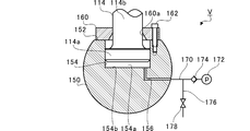
- FIG. 2 is an extraction diagram in which a connecting portion between the piston rod 114 and the crosshead pin 150 is extracted. As shown in FIG. 2, a flat portion 152 is formed on the outer peripheral surface of the cross head pin 150 on the piston 112 side. The plane portion 152 extends in a direction substantially perpendicular to the stroke direction of the piston 112.
- a pin hole 154 is formed in the crosshead pin 150.
- the pin hole 154 opens in the flat portion 152.
- the pin hole 154 extends from the flat portion 152 to the crankshaft 120 side (lower side in FIG. 2) along the stroke direction.
- a cover member 160 is provided on the flat portion 152 of the cross head pin 150. Cover member 160 is attached to flat portion 152 of crosshead pin 150 by fastening member 162. The cover member 160 covers the pin hole 154. The cover member 160 is provided with a cover hole 160a penetrating in the stroke direction.
- the piston rod 114 has a large diameter part 114a and a small diameter part 114b.
- the outer diameter of the large diameter portion 114a is larger than the outer diameter of the small diameter portion 114b.
- the large diameter portion 114 a is formed at the other end of the piston rod 114.
- the large diameter portion 114 a is inserted into the pin hole 154 of the cross head pin 150.
- the small diameter portion 114b is formed on one end side of the piston rod 114 from the large diameter portion 114a.
- the small diameter portion 114 b is inserted through the cover hole 160 a of the cover member 160.
- the hydraulic chamber 154 a is formed inside the pin hole 154.
- the pin hole 154 is partitioned in the stroke direction by the large diameter portion 114a.
- the hydraulic chamber 154a is a space on the bottom surface 154b side of the pin hole 154 partitioned by the large diameter portion 114a.
- An oil passage 156 opens on the bottom surface 154b.
- the other end of the oil passage 156 opens to the outside of the cross head pin 150.
- a hydraulic pipe 170 is connected to the other end of the oil passage 156.
- a hydraulic pump 172 communicates with the hydraulic piping 170.
- a check valve 174 is provided between the hydraulic pump 172 and the oil passage 156. The check valve 174 suppresses the flow of hydraulic oil from the oil passage 156 side to the hydraulic pump 172 side. The hydraulic oil is pressed into the hydraulic chamber 154a from the hydraulic pump 172 through the oil passage 156.
- a branch pipe 176 is connected between the oil passage 156 and the check valve 174 in the hydraulic pipe 170.
- the branch pipe 176 is provided with a switching valve 178.
- the switching valve 178 is, for example, an electromagnetic valve. During the operation of the hydraulic pump 172, the switching valve 178 is closed. When the switching valve 178 is opened while the hydraulic pump 172 is stopped, the hydraulic oil is discharged from the hydraulic chamber 154a to the branch pipe 176 side. Of the switching valve 178, the side opposite to the oil passage 156 communicates with an oil tank (not shown). The discharged hydraulic oil is stored in the oil tank. The oil tank supplies hydraulic oil to the hydraulic pump 172.
- the large diameter portion 114a slides on the inner peripheral surface of the pin hole 154 in the stroke direction according to the amount of hydraulic oil in the hydraulic chamber 154a. As a result, the piston rod 114 moves in the stroke direction.
- the piston 112 moves integrally with the piston rod 114. Thus, the top dead center position of the piston 112 becomes variable.
- the marine engine 100 includes a compression ratio variable mechanism V.
- the compression ratio variable mechanism V includes the hydraulic chamber 154a and the large diameter portion 114a of the piston rod 114.
- the compression ratio variable mechanism V makes the compression ratio variable by moving the top dead center position of the piston 112.
- the space on the cover member 160 side in the pin hole 154 partitioned by the large diameter portion 114a may be a hydraulic chamber.
- This hydraulic chamber may be used together with the hydraulic chamber 154a or may be used alone.
- FIG. 3 is a functional block diagram of the marine engine 100.
- FIG. 3 mainly shows a configuration related to the control of the compression ratio variable mechanism V.
- the marine engine 100 includes a control device 180.
- the control device 180 is configured by an ECU (Engine Control Unit), for example.
- the control device 180 includes a central processing unit (CPU), a ROM storing programs, a RAM as a work area, and the like, and controls the marine engine 100 as a whole.
- the control device 180 functions as the compression ratio control unit 182.
- the compression ratio control unit 182 controls the hydraulic pump 172 and the switching valve 178 to move the top dead center position of the piston 112. Specifically, the control device 180 receives a signal indicating the engine speed from the rotation sensor Sa. The control device 180 receives a signal indicating the crank angle from the pulse counter Sb. The compression ratio control unit 182 moves the piston 112 to the bottom dead center side when the engine speed indicated by the signal from the rotation sensor Sa is included in the preset resonance generation range. Perform the process.
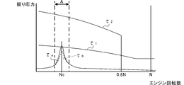
- FIG. 4 is a diagram for explaining the bird range A.
- the horizontal axis represents the engine speed
- the vertical axis represents the torsional stress acting on the rotating shaft system such as the crankshaft 120.
- the rotating shaft system includes an allowable stress of torsional stress (allowable stress line ⁇ 1 in FIG. 4) and a limit stress (limit stress line ⁇ in FIG. 4) according to the engine speed. 2 ) is provided.
- the allowable stress is a limit value of stress within a range that can be safely used.
- the critical stress is the maximum stress that can be withstood without being discarded.
- torsional vibration When torsional vibration is applied from the piston 112 to the rotating shaft system, torsional vibration occurs. At this time, if the rotating shaft system resonates, the torsional stress (high compression ratio torsional stress ⁇ a and low compression ratio torsional stress ⁇ b in FIG. 4) will extremely increase. Therefore, in a conventional marine engine, the torsional stress may exceed the allowable stress depending on the design.
- a bird range A is provided.
- the engine output is automatically controlled so that the engine speed deviates from the bird range A. Therefore, the torsional stress increase interval is shortened.
- navigation in bird range A cannot be maintained, operability is reduced.
- FIG. 5 (a) is a diagram for explaining the relationship between the torque acting on the crankshaft 120 and the compression ratio.
- FIG.5 (b) is a figure which shows the result of having carried out the harmonic analysis of the fluctuation
- 5A and 5B the vertical axis represents the torque acting on the crankshaft 120.
- 5A and 5B the horizontal axis indicates the crank angle.
- FIG. 5 (b) up to the third order component is shown, and the illustration after the fourth order component is omitted.
- the amplitude decreases as the first-order component, second-order component, third-order component, and higher-order component. That is, the primary component has the largest influence on the amplitude in the variation of the torque of the analysis source shown in FIG.
- the amplitude in the primary component is smaller in the case of the low compression ratio indicated by the broken line in FIG. 5B than in the case of the high compression ratio indicated by the solid line. This indicates that the excitation force (excitation torque) was suppressed by lowering the compression ratio.
- the torsional stress due to torque fluctuation is also smaller in the case of a low compression ratio than in the case of a high compression ratio.
- the compression ratio control unit 182 moves the piston 112 to the bottom dead center side when the engine speed indicated by the signal from the rotation sensor Sa is included in the preset resonance generation range. Perform the process.
- the resonance generation range is, for example, a range of engine speed at which the torsional stress may exceed the allowable stress.
- the bird range A shown in FIG. 4 is set as the resonance generation range.
- a high compression ratio torsional stress ⁇ a is greater than allowable stress lines tau 1.
- the compression ratio control unit 182 moves the top dead center position of the piston 112 to the bottom dead center side so that the torsional stress of the crankshaft 120 approaches the allowable stress of the crankshaft 120 (lowering process).
- the crank angle is specified by the signal from the pulse counter Sb
- the rotation fluctuation of the crankshaft 120 is specified from the fluctuation. That is, the pulse counter Sb functions as a detection unit that detects rotational fluctuation of the crankshaft 120.
- the compression ratio control unit 182 derives the torsional stress from the rotation fluctuation detected by the pulse counter Sb. Then, the compression ratio control unit 182 feedback-controls the top dead center position of the piston 112 so that the torsional stress approaches the allowable stress.
- torsional stress ⁇ a does not exceed the allowable stress lines tau 1
- the top dead center position of the piston 112 is moved to the bottom dead center.
- the torsional stress is positioned in the vicinity of the allowable stress line ⁇ 1 without being significantly lower than the allowable stress line ⁇ 1 by feedback control.
- the compression ratio control unit 182 performs the descending process, the torsional stress can be suppressed even if resonance occurs. Therefore, the engine output does not need to be automatically controlled so that the engine speed deviates from the bird range A as described above. That is, since navigation in bird range A can be maintained, operability is improved.
- the above feedback control prevents the piston 112 from moving to the bottom dead center side until it is unnecessary. That is, to the extent that torsional stress is the allowable stress lines tau 1 below, as much as possible compression ratio is maintained high. A reduction in thermal efficiency is suppressed by maintaining the compression ratio high.
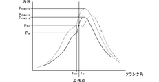
- FIG. 6 is a diagram for explaining changes in the cylinder internal pressure.
- the vertical axis indicates the cylinder internal pressure
- the horizontal axis indicates the crank angle.
- the cylinder internal pressure rises to the pressure P max-b as it is.
- the torsional stress ⁇ a may exceed the allowable stress depending on the design.
- valve closing timing of the exhaust valve 130 is retarded without the variable compression ratio mechanism V being provided.
- the geometric compression ratio cannot be varied, but the theoretical compression ratio can be lowered.
- the rotating shaft system is designed so as to avoid the normal range and become a low load range. Since the supercharger C does not function sufficiently in the low load region, the air in the scavenging chamber 140a is not sufficiently compressed. Therefore, the amount of air in the combustion chamber 128 tends to decrease. In such a situation, if the valve closing timing of the exhaust valve 130 is retarded, the amount of air in the combustion chamber 128 is further reduced and the thermal efficiency is deteriorated.
- the compression ratio is lowered by the variable compression ratio mechanism V. Therefore, compared with the case where the fuel injection timing and the closing timing of the exhaust valve 130 are controlled to be retarded, the reduction in thermal efficiency is suppressed. It becomes possible to suppress the resonance stress of torsional vibration of the rotating shaft system.
- FIG. 7 is a flowchart showing the flow of the descending process by the compression ratio control unit 182. The process shown in FIG. 7 is repeatedly executed at a predetermined cycle.
- the compression ratio control unit 182 determines whether or not the engine speed is included in the resonance generation range. If included in the resonance generation range, the process proceeds to S202. If it is not included in the resonance generation range, the descent process is terminated.
- the compression ratio control unit 182 derives the torsional stress from the rotation fluctuation detected by the pulse counter Sb.
- the compression ratio control unit 182 feedback-controls the top dead center position of the piston 112 so that the torsional stress approaches the allowable stress within a range not exceeding the allowable stress, and ends the descending process.
- the two-cycle type, uniflow scavenging type, crosshead type marine engine 100 has been described as an example.
- the type of engine is not limited to the two-cycle type, the uniflow scavenging type, and the crosshead type. Any marine engine may be used.
- liquid fuel for example, gaseous fuel may be used.
- a gaseous fuel injection valve is provided in the vicinity of the scavenging port 110 a or in a portion of the cylinder 110 from the scavenging port 110 a to the cylinder cover 124.
- the fuel gas is injected from the gaseous fuel injection valve and then flows into the cylinder 110.
- the fuel injection valve 142 When a small amount of liquid fuel is injected from the fuel injection valve 142, the mixture of fuel gas and active gas is ignited and burned by the combustion heat.
- the fuel gas is gasified from LNG, LPG (liquefied petroleum gas), light oil, heavy oil and the like.
- the marine engine 100 may be, for example, a dual fuel type that selectively uses gaseous fuel and liquid fuel.
- the compression ratio control unit 182 controls the piston 112 so that the torsional stress of the crankshaft 120 approaches the allowable stress of the crankshaft 120 when the engine speed is included in the resonance generation range.
- the case where the dead center position is controlled has been described.
- the compression ratio control unit 182 may perform a descent process that moves the top dead center position of the piston 112 to the bottom dead center side at least when the engine speed is included in the resonance generation range.
- the compression ratio control unit 182 feedback-controls the top dead center position of the piston 112 so that the torsional stress specified from the detected rotational fluctuation approaches the allowable stress.
- the feedback control may not be performed.
- the compression ratio control unit 182 performs the descending process when the engine speed indicated by the signal from the rotation sensor Sa is included in the preset resonance generation range.
- the compression ratio control unit 182 may use other parameters that are roughly linked to the engine speed instead of the engine speed. In any case, when the engine speed is included in the preset resonance generation range, the descending process may be performed.
- the compression ratio variable mechanism V may have any configuration as long as the compression ratio can be changed by changing the top dead center position of the piston 112. Good.
- a hydraulic pressure generator as described in Japanese Patent Application Laid-Open No. 2016-212462 may be provided.
- This disclosure can be used for marine engines.
Landscapes
- Engineering & Computer Science (AREA)
- Chemical & Material Sciences (AREA)
- Combustion & Propulsion (AREA)
- Mechanical Engineering (AREA)
- General Engineering & Computer Science (AREA)
- Ocean & Marine Engineering (AREA)
- Output Control And Ontrol Of Special Type Engine (AREA)
- Electrical Control Of Air Or Fuel Supplied To Internal-Combustion Engine (AREA)
Abstract
Description
圧縮比制御部182は、エンジン回転数が共振発生範囲に含まれるか否かを判定する。共振発生範囲に含まれれば、S202に処理を移す。共振発生範囲に含まれなければ、当該下降処理を終了する。
圧縮比制御部182は、パルスカウンタSbによって検出された回転変動から捩り応力を導出する。
圧縮比制御部182は、捩り応力が許容応力を超えない範囲で許容応力に近づくように、ピストン112の上死点位置をフィードバック制御し、当該下降処理を終了する。
Claims (3)
- ピストンと、
エンジン回転数が、予め設定された共振発生範囲に含まれるとき、前記ピストンの上死点位置を下死点側に移動させる下降処理を遂行する圧縮比制御部と、
を備える舶用エンジン。 - 前記圧縮比制御部は、エンジン回転数が前記共振発生範囲に含まれるとき、クランクシャフトの捩り応力が、前記クランクシャフトの許容応力に近づくように、前記ピストンの上死点位置を制御する請求項1に記載の舶用エンジン。
- 前記クランクシャフトの回転変動を検出する検出部を備え、
前記圧縮比制御部は、検出された前記回転変動から特定される前記捩り応力が前記許容応力に近づくように、前記ピストンの上死点位置をフィードバック制御する請求項2に記載の舶用エンジン。
Priority Applications (5)
| Application Number | Priority Date | Filing Date | Title |
|---|---|---|---|
| EP19767911.1A EP3767094B1 (en) | 2018-03-16 | 2019-03-14 | Marine engine |
| DK19767911.1T DK3767094T3 (da) | 2018-03-16 | 2019-03-14 | Skibsmotor |
| KR1020207021327A KR102312788B1 (ko) | 2018-03-16 | 2019-03-14 | 선박용 엔진 |
| CN201980019829.7A CN111836955B (zh) | 2018-03-16 | 2019-03-14 | 船舶用发动机 |
| US16/894,749 US11131254B2 (en) | 2018-03-16 | 2020-06-05 | Marine engine |
Applications Claiming Priority (2)
| Application Number | Priority Date | Filing Date | Title |
|---|---|---|---|
| JP2018050004A JP6866325B2 (ja) | 2018-03-16 | 2018-03-16 | 舶用エンジン |
| JP2018-050004 | 2018-03-16 |
Related Child Applications (1)
| Application Number | Title | Priority Date | Filing Date |
|---|---|---|---|
| US16/894,749 Continuation US11131254B2 (en) | 2018-03-16 | 2020-06-05 | Marine engine |
Publications (1)
| Publication Number | Publication Date |
|---|---|
| WO2019177108A1 true WO2019177108A1 (ja) | 2019-09-19 |
Family
ID=67907208
Family Applications (1)
| Application Number | Title | Priority Date | Filing Date |
|---|---|---|---|
| PCT/JP2019/010588 Ceased WO2019177108A1 (ja) | 2018-03-16 | 2019-03-14 | 舶用エンジン |
Country Status (7)
| Country | Link |
|---|---|
| US (1) | US11131254B2 (ja) |
| EP (1) | EP3767094B1 (ja) |
| JP (1) | JP6866325B2 (ja) |
| KR (1) | KR102312788B1 (ja) |
| CN (1) | CN111836955B (ja) |
| DK (1) | DK3767094T3 (ja) |
| WO (1) | WO2019177108A1 (ja) |
Cited By (1)
| Publication number | Priority date | Publication date | Assignee | Title |
|---|---|---|---|---|
| NO20200639A1 (no) * | 2020-05-29 | 2021-11-30 | Lars Harald Heggen | Gassveksling i forbrenningsmotorer for økt virkningsgrad |
Families Citing this family (3)
| Publication number | Priority date | Publication date | Assignee | Title |
|---|---|---|---|---|
| JP7127003B2 (ja) * | 2019-10-30 | 2022-08-29 | 株式会社Ihi原動機 | エンジン |
| JP7507698B2 (ja) * | 2021-01-13 | 2024-06-28 | 株式会社三井E&S Du | エンジン |
| CN118669392B (zh) * | 2024-08-22 | 2025-01-24 | 武汉理工大学 | 一种船用低速机各气缸压缩比一致性测试装置及测试方法 |
Citations (7)
| Publication number | Priority date | Publication date | Assignee | Title |
|---|---|---|---|---|
| JPS634307B2 (ja) | 1980-06-13 | 1988-01-28 | Hitachi Ltd | |
| JP2001123857A (ja) * | 1996-07-18 | 2001-05-08 | Toyota Motor Corp | 駆動装置 |
| JP2007032388A (ja) * | 2005-07-26 | 2007-02-08 | Denso Corp | 内燃機関の始動制御装置 |
| JP2007170198A (ja) * | 2005-12-19 | 2007-07-05 | Toyota Motor Corp | 内燃機関のトルク制御装置 |
| JP2010242690A (ja) * | 2009-04-09 | 2010-10-28 | Nissan Motor Co Ltd | 可変圧縮比内燃機関の制御装置 |
| JP2016211462A (ja) | 2015-05-11 | 2016-12-15 | 株式会社Ihi | 油圧発生装置およびクロスヘッド型エンジン |
| JP2018050004A (ja) | 2016-09-23 | 2018-03-29 | 東芝メモリ株式会社 | 半導体装置の製造方法 |
Family Cites Families (18)
| Publication number | Priority date | Publication date | Assignee | Title |
|---|---|---|---|---|
| JP3004307B2 (ja) | 1990-03-23 | 2000-01-31 | 三菱重工業株式会社 | ディーゼル機関のクランク軸ねじり振動抑制装置 |
| JP3004307U (ja) | 1994-05-17 | 1994-11-15 | 幸子 横田 | 靴の汚損防止具 |
| JP3250483B2 (ja) | 1996-07-18 | 2002-01-28 | トヨタ自動車株式会社 | 駆動装置 |
| JP4640236B2 (ja) | 2006-04-05 | 2011-03-02 | 日産自動車株式会社 | 内燃機関の始動装置 |
| KR100921806B1 (ko) * | 2007-11-29 | 2009-10-16 | 현대자동차주식회사 | 가변 압축비 장치 |
| JP2010223068A (ja) * | 2009-03-23 | 2010-10-07 | Hitachi Automotive Systems Ltd | 内燃機関の制御装置 |
| JP4788797B2 (ja) * | 2009-03-31 | 2011-10-05 | マツダ株式会社 | 過給機付き直噴エンジン |
| JP5040951B2 (ja) * | 2009-03-31 | 2012-10-03 | マツダ株式会社 | 直噴エンジンの制御方法および直噴エンジン |
| BRPI0904330B1 (pt) * | 2009-04-02 | 2021-06-08 | Toyota Jidosha Kabushiki Kaisha | sistema de controle de motor |
| JP5621761B2 (ja) * | 2011-12-12 | 2014-11-12 | トヨタ自動車株式会社 | 可変圧縮比機構を備える内燃機関を搭載する車両 |
| JP5795731B2 (ja) * | 2011-12-16 | 2015-10-14 | 川崎重工業株式会社 | ねじり振動応力低減制御装置、これを備えた船舶、及びねじり振動応力低減方法 |
| JP5942805B2 (ja) * | 2012-11-16 | 2016-06-29 | トヨタ自動車株式会社 | 火花点火式内燃機関 |
| JP6025640B2 (ja) * | 2013-03-28 | 2016-11-16 | 三菱重工業株式会社 | エンジンの失火時負荷制御方法およびその失火時負荷制御システム |
| DE102014002368B4 (de) * | 2013-11-14 | 2015-11-12 | Audi Ag | Mehrgelenkskurbeltrieb einer Brennkraftmaschine sowie entsprechende Brennkraftmaschine |
| WO2015108138A1 (ja) * | 2014-01-20 | 2015-07-23 | 株式会社Ihi | クロスヘッド型エンジン |
| DK3098416T3 (en) * | 2014-01-20 | 2018-12-10 | Ihi Corp | crosshead |
| CN107002563B (zh) * | 2014-12-09 | 2020-06-12 | 日产自动车株式会社 | 内燃机的控制装置 |
| JP6515710B2 (ja) * | 2015-07-07 | 2019-05-22 | 日産自動車株式会社 | 内燃機関の制御装置 |
-
2018
- 2018-03-16 JP JP2018050004A patent/JP6866325B2/ja active Active
-
2019
- 2019-03-14 CN CN201980019829.7A patent/CN111836955B/zh active Active
- 2019-03-14 KR KR1020207021327A patent/KR102312788B1/ko active Active
- 2019-03-14 DK DK19767911.1T patent/DK3767094T3/da active
- 2019-03-14 EP EP19767911.1A patent/EP3767094B1/en active Active
- 2019-03-14 WO PCT/JP2019/010588 patent/WO2019177108A1/ja not_active Ceased
-
2020
- 2020-06-05 US US16/894,749 patent/US11131254B2/en active Active
Patent Citations (7)
| Publication number | Priority date | Publication date | Assignee | Title |
|---|---|---|---|---|
| JPS634307B2 (ja) | 1980-06-13 | 1988-01-28 | Hitachi Ltd | |
| JP2001123857A (ja) * | 1996-07-18 | 2001-05-08 | Toyota Motor Corp | 駆動装置 |
| JP2007032388A (ja) * | 2005-07-26 | 2007-02-08 | Denso Corp | 内燃機関の始動制御装置 |
| JP2007170198A (ja) * | 2005-12-19 | 2007-07-05 | Toyota Motor Corp | 内燃機関のトルク制御装置 |
| JP2010242690A (ja) * | 2009-04-09 | 2010-10-28 | Nissan Motor Co Ltd | 可変圧縮比内燃機関の制御装置 |
| JP2016211462A (ja) | 2015-05-11 | 2016-12-15 | 株式会社Ihi | 油圧発生装置およびクロスヘッド型エンジン |
| JP2018050004A (ja) | 2016-09-23 | 2018-03-29 | 東芝メモリ株式会社 | 半導体装置の製造方法 |
Non-Patent Citations (1)
| Title |
|---|
| See also references of EP3767094A4 |
Cited By (2)
| Publication number | Priority date | Publication date | Assignee | Title |
|---|---|---|---|---|
| NO20200639A1 (no) * | 2020-05-29 | 2021-11-30 | Lars Harald Heggen | Gassveksling i forbrenningsmotorer for økt virkningsgrad |
| NO348568B1 (no) * | 2020-05-29 | 2025-03-10 | Lars Harald Heggen | Gassveksling i forbrenningsmotorer for økt virkningsgrad |
Also Published As
| Publication number | Publication date |
|---|---|
| US11131254B2 (en) | 2021-09-28 |
| JP2019157843A (ja) | 2019-09-19 |
| EP3767094A4 (en) | 2021-12-15 |
| JP6866325B2 (ja) | 2021-04-28 |
| CN111836955B (zh) | 2022-12-06 |
| EP3767094B1 (en) | 2025-10-01 |
| EP3767094A1 (en) | 2021-01-20 |
| DK3767094T3 (da) | 2025-10-20 |
| CN111836955A (zh) | 2020-10-27 |
| US20200300183A1 (en) | 2020-09-24 |
| KR102312788B1 (ko) | 2021-10-13 |
| KR20200096654A (ko) | 2020-08-12 |
Similar Documents
| Publication | Publication Date | Title |
|---|---|---|
| KR101894085B1 (ko) | 크로스헤드형 엔진 | |
| WO2019177108A1 (ja) | 舶用エンジン | |
| JP5452730B2 (ja) | 2ストロークエンジン | |
| JP6137340B2 (ja) | クロスヘッド型エンジン | |
| JP6868584B2 (ja) | エンジン | |
| JP6003288B2 (ja) | ユニフロー掃気式2サイクルエンジン | |
| CN110352294B (zh) | 单流扫气式二冲程发动机 | |
| CN111886404B (zh) | 发动机 | |
| WO2019177106A1 (ja) | 舶用エンジン | |
| SE531337C2 (sv) | Bränsledriven brytmaskin | |
| JP6878340B2 (ja) | エンジン | |
| JP6878339B2 (ja) | エンジン | |
| JP7507698B2 (ja) | エンジン | |
| JP7421854B2 (ja) | エンジン | |
| JP2026066002A (ja) | ピストン、内燃機関、及び、車両 | |
| WO2019103085A1 (ja) | 可変圧縮装置及びエンジンシステム |
Legal Events
| Date | Code | Title | Description |
|---|---|---|---|
| 121 | Ep: the epo has been informed by wipo that ep was designated in this application |
Ref document number: 19767911 Country of ref document: EP Kind code of ref document: A1 |
|
| ENP | Entry into the national phase |
Ref document number: 20207021327 Country of ref document: KR Kind code of ref document: A |
|
| NENP | Non-entry into the national phase |
Ref country code: DE |
|
| WWE | Wipo information: entry into national phase |
Ref document number: 2019767911 Country of ref document: EP |
|
| WWG | Wipo information: grant in national office |
Ref document number: 2019767911 Country of ref document: EP |