WO2019181674A1 - 状態監視装置、状態監視システム、状態監視方法および記録媒体 - Google Patents
状態監視装置、状態監視システム、状態監視方法および記録媒体 Download PDFInfo
- Publication number
- WO2019181674A1 WO2019181674A1 PCT/JP2019/010167 JP2019010167W WO2019181674A1 WO 2019181674 A1 WO2019181674 A1 WO 2019181674A1 JP 2019010167 W JP2019010167 W JP 2019010167W WO 2019181674 A1 WO2019181674 A1 WO 2019181674A1
- Authority
- WO
- WIPO (PCT)
- Prior art keywords
- communication
- state monitoring
- information
- mobile
- operation information
- Prior art date
- Legal status (The legal status is an assumption and is not a legal conclusion. Google has not performed a legal analysis and makes no representation as to the accuracy of the status listed.)
- Ceased
Links
Images







Classifications
-
- H—ELECTRICITY
- H04—ELECTRIC COMMUNICATION TECHNIQUE
- H04Q—SELECTING
- H04Q9/00—Arrangements in telecontrol or telemetry systems for selectively calling a substation from a main station, in which substation desired apparatus is selected for applying a control signal thereto or for obtaining measured values therefrom
-
- H—ELECTRICITY
- H04—ELECTRIC COMMUNICATION TECHNIQUE
- H04L—TRANSMISSION OF DIGITAL INFORMATION, e.g. TELEGRAPHIC COMMUNICATION
- H04L12/00—Data switching networks
- H04L12/28—Data switching networks characterised by path configuration, e.g. LAN [Local Area Networks] or WAN [Wide Area Networks]
- H04L12/2803—Home automation networks
- H04L12/2816—Controlling appliance services of a home automation network by calling their functionalities
- H04L12/2818—Controlling appliance services of a home automation network by calling their functionalities from a device located outside both the home and the home network
-
- H—ELECTRICITY
- H04—ELECTRIC COMMUNICATION TECHNIQUE
- H04L—TRANSMISSION OF DIGITAL INFORMATION, e.g. TELEGRAPHIC COMMUNICATION
- H04L43/00—Arrangements for monitoring or testing data switching networks
- H04L43/06—Generation of reports
- H04L43/065—Generation of reports related to network devices
-
- H—ELECTRICITY
- H04—ELECTRIC COMMUNICATION TECHNIQUE
- H04W—WIRELESS COMMUNICATION NETWORKS
- H04W24/00—Supervisory, monitoring or testing arrangements
- H04W24/08—Testing, supervising or monitoring using real traffic
-
- H—ELECTRICITY
- H04—ELECTRIC COMMUNICATION TECHNIQUE
- H04W—WIRELESS COMMUNICATION NETWORKS
- H04W76/00—Connection management
- H04W76/10—Connection setup
-
- G—PHYSICS
- G08—SIGNALLING
- G08C—TRANSMISSION SYSTEMS FOR MEASURED VALUES, CONTROL OR SIMILAR SIGNALS
- G08C2201/00—Transmission systems of control signals via wireless link
- G08C2201/90—Additional features
- G08C2201/93—Remote control using other portable devices, e.g. mobile phone, PDA, laptop
-
- H—ELECTRICITY
- H04—ELECTRIC COMMUNICATION TECHNIQUE
- H04M—TELEPHONIC COMMUNICATION
- H04M11/00—Telephonic communication systems specially adapted for combination with other electrical systems
- H04M11/002—Telephonic communication systems specially adapted for combination with other electrical systems with telemetering systems
-
- H—ELECTRICITY
- H04—ELECTRIC COMMUNICATION TECHNIQUE
- H04Q—SELECTING
- H04Q2209/00—Arrangements in telecontrol or telemetry systems
- H04Q2209/40—Arrangements in telecontrol or telemetry systems using a wireless architecture
-
- H—ELECTRICITY
- H04—ELECTRIC COMMUNICATION TECHNIQUE
- H04Q—SELECTING
- H04Q2209/00—Arrangements in telecontrol or telemetry systems
- H04Q2209/40—Arrangements in telecontrol or telemetry systems using a wireless architecture
- H04Q2209/43—Arrangements in telecontrol or telemetry systems using a wireless architecture using wireless personal area networks [WPAN], e.g. 802.15, 802.15.1, 802.15.4, Bluetooth® or Zigbee®
-
- H—ELECTRICITY
- H04—ELECTRIC COMMUNICATION TECHNIQUE
- H04W—WIRELESS COMMUNICATION NETWORKS
- H04W24/00—Supervisory, monitoring or testing arrangements
- H04W24/04—Arrangements for maintaining operational condition
Definitions
- the present invention relates to a state monitoring device for reliably monitoring the state of a target device.
- Patent Document 1 discloses a technique for monitoring and judging deterioration of a power storage system.
- Patent Document 2 discloses a technique for causing a user to select a malfunction state of a home appliance via a mobile terminal and analyzing the malfunction on the server side based on the selection result.
- Patent Document 3 discloses a technique for detecting an abnormality in the air survey device in consideration of the state.
- Patent Documents 1 to 3 are based on the premise that the communication environment such as the Internet is established in a country or country, and the device or system to be monitored is a place where the communication environment is poor. It is not considered to be installed in areas where infrastructure facilities are not developed.
- the present invention provides a status monitoring device and the like that can reliably deliver status monitoring information of a monitoring target device placed in a remote place with a poor communication environment to the maintenance staff. Objective.
- the state monitoring device is: The first communication line for transmitting the operation information of the target device to be monitored to the server device, and the server device via the wireless communication provided by the mobile unit when the first communication line cannot communicate with the server device.
- a second communication line for transmitting driving information; The communication means which communicates using is provided.
- the state monitoring system is: A state monitoring device as described above; When the operation information of the target device monitored by the state monitoring device cannot be transmitted via the first communication line, the wireless device moves to a position where wireless communication is possible with the state monitoring device and connects the wireless communication. A moving object, And a server device that receives the operation information between the device and the state monitoring device via a second communication line that uses the wireless communication.
- the state monitoring method is: The first communication line for transmitting the operation information of the target device to be monitored to the server device, and the server device via the wireless communication provided by the mobile unit when the first communication line cannot communicate with the server device.
- the state monitoring program that is the fourth aspect of the present invention is: When the first communication line for transmitting the operation information of the target device to be monitored to the server device and the first communication line cannot communicate, the wireless communication provided by the mobile body is used for the server device.
- a second communication line for transmitting the driving information Communicating using a computer.
- state monitoring program may be stored in a non-transitory computer-readable storage medium.
- a status monitoring device or the like that can reliably deliver status monitoring information of a monitoring target device placed in a remote place with a poor communication environment to the maintenance staff.
- FIG. 1 It is a block diagram which shows the structural example of the state monitoring system concerning the 1st Embodiment of this invention. It is a figure which shows the internal structural example of a state monitoring apparatus. It is a figure which shows the example of the table
- a system related to a human lifeline for example, electricity, communication, water supply
- the system cannot be stopped all day, and maintenance and monitoring of the system are essential.
- maintenance management of these systems is performed remotely, maintenance personnel receive information on the systems via a communication network, and when a failure occurs, measures for failure recovery are implemented.
- a communication environment for transmitting and receiving the operating status of the system is prepared.
- a system subject to maintenance management may be installed in a place with a poor communication environment.
- a storage battery system prepared in the event of an emergency in a power system such as a communication base station may be installed in a mountainous area where the communication environment is poor. Or, it may be installed in an area where the infrastructure environment is not established, such as a power outage several times a day.
- a power outage several times a day.
- the communication network is interrupted, maintenance personnel cannot obtain information on the operating status of the monitored system, and even if the system fails, the maintenance The cause cannot be known immediately. Therefore, there is a need for an alternative means of communication for reliably transmitting the information on the monitored system to the maintenance staff even in a place where the communication environment is poor.
- a device arranged in a place where the communication environment is bad when realizing the scheduled operation by suppressing the power output requested by the electric power company.
- the maintenance staff visits the installation location and sets the schedule. Even in the case of such maintenance of schedule settings, being able to perform setting remotely via communication for a device in a place with a poor communication environment reduces the burden on maintenance personnel.
- a state monitoring system 100 includes a state monitoring device 1, a moving body 2, and a maintenance server 3.
- the state monitoring device 1 is communicably connected to the inside or outside of a monitoring target device (for example, a storage battery system), and monitors the operation state of the monitoring target device.
- the state monitoring device 1 is normally connected to a network 4 (for example, the Internet), and transmits the operation state of the monitored device to the maintenance server 3 as operation information via the network 4 (this is the first communication). Also called).
- the state monitoring device 1 wirelessly connects to the mobile unit 2.
- Request a communication connection The mobile body 2 is a terminal that can move and wirelessly communicate. For example, a drone having a wireless communication function in a flight system, a small car having a wireless communication function in a land system, and the like correspond to this. .
- the mobile unit 2 transmits the operation information of the state monitoring device received via wireless communication to the maintenance server 3 via the network 4 (also referred to as second communication).
- the moving body 2 may be set to move (circulate) around the state monitoring device 1 at a predetermined interval.
- the mobile body 2 is not limited to the above, and may be, for example, a smartphone or a personal computer having a wireless communication function.
- a smartphone or personal computer that exists in a place where wireless communication with the state monitoring device 1 can be performed is detected, and for example, a tethering function is used for the detected smartphone or personal computer. Requests that the operation information of the target device be transmitted to the network 4.
- the maintenance server 3 analyzes the operation information received from the state monitoring device 1 and analyzes the operation state of the monitoring target device. In addition, when communication between the state monitoring device 1 and the maintenance server 3 is interrupted, not only the state monitoring device 1 but also the maintenance server 3 detects this, and the mobile unit 2 communicates with the state monitoring device 1. You may request to move to a position where wireless communication is possible and connect wireless communication.
- the maintenance server 3 may be a server (cloud server) created in a cloud environment.
- the wireless communication provided by the network 4 and the mobile unit 2 may be any type of communication.
- short-range wireless such as NFC (Near-field communication), wireless PAN (Personal Area Network) such as Bluetooth (registered trademark), wireless LAN (Local Area Network) such as Wi-Fi (Wireless Fidelity; registered trademark), wireless such as WiMax MAN (MetropolitanpoliArea Network).
- the mobile unit 2 may be equipped with a plurality of types of wireless communication functions. For example, it is assumed that the mobile body 2 has three communication functions of wireless LAN, wireless PAN, and short-range wireless.
- the moving body 2 moves itself to a position closer to the state monitoring apparatus 1, and the wireless PAN Driving information is acquired from the state monitoring device 1 via the distance radio.
- the mobile unit 2 moves itself to a position where it can communicate with the network 4 via the wireless LAN or the wireless MAN, and transmits the acquired driving information to the maintenance server 3 side.
- the state monitoring device 1 includes an operation information collection unit 11, an operation information storage unit 12, a failure detection unit 13, a display unit 14, and a communication unit 15.
- the operation information collection unit 11 collects operation information (operation state information and failure information) of the monitoring target device from a sensor attached to the monitoring target device.
- the driving information storage unit 12 stores driving information.
- the operation information includes operation state information and failure information.
- the operation state information is, for example, a real-time operation log of the monitoring target device.
- the failure information is, for example, an error code and failure severity.
- the operation information includes a monitoring target device ID (IDentifier), a time stamp, and a maintenance server address.
- Operation log includes event log, setting value log, and measurement value log.
- the event log is a log indicating that some event has occurred in the monitored device.
- the setting value log is a log indicating setting values set in the monitoring target device when an operation schedule is set.
- the measurement value log is a real-time operation log of the monitoring target device. For example, in the case of a storage battery system, measurement values of voltage, current, and temperature correspond to this.
- the error code is, for example, a code or several character strings for specifying the type of error when an error occurs in the monitored device.
- Failure severity is information indicating the degree of failure, and is classified into three ranks, for example, “severe”, “mild”, and “unknown”.
- “severe” is a fatal failure related to battery safety such as overcharge, overdischarge, and overcurrent. In this case, maintenance personnel need to stop the system immediately.
- “Minor” refers to, for example, a relay failure of a power conditioner or a unit failure based on a detection result of no communication with the unit, and a failure that requires automatic recovery. In this case, it is necessary to attempt to reset the unit via remote control or autonomously.
- Unknown is a failure that requires the system to stop operating temporarily, although the cause of direct failure, such as system instantaneous overvoltage or system power abnormality, is unknown.
- the external cause of the failure may be resolved by waiting for a certain period. If the failure is not resolved even after waiting for a certain period, the failure severity may be set to “mild” or “severe”.
- the content of the failure severity and the number of ranks are not limited to the above, and can be changed according to the operation status of the monitoring target device.
- the monitoring target device ID is an identifier for uniquely identifying the monitoring target device.
- the time stamp is a stamp indicating the time when the driving information is generated.
- the maintenance server address is the destination address of the maintenance server 3.
- the failure detection unit 13 detects the failure of the monitored device and determines the failure severity based on the current operation information sent from the operation information collection unit 11 and the past operation information acquired from the operation information storage unit 12.
- the display unit 14 is a display device for displaying at least one of the presence / absence of a failure, the severity of failure, and the presence / absence of information transmission to the mobile body 2, for example, a display device or a lamp.
- the communication unit 15 communicates with the maintenance server 3 via the network 4.
- the communication unit 15 provides the first communication line for transmitting the operation information of the monitoring target device to the maintenance server 3 when the communication is normal, and the wireless provided by the mobile unit 2 when the first communication line cannot communicate.
- a second communication line for transmitting operation information to the maintenance server 3 via communication can be used.
- the communication unit 15 detects that communication via the first communication line is impossible for some reason, the communication unit 15 searches for the mobile unit 2 and requests connection to wireless communication provided by the mobile unit 2. Further, the communication unit 15 may request the mobile body 2 for information on disconnection of communication (for example, the position and time of disconnection).
- the communication unit 15 may measure communication quality on the second communication line and select operation information to be transmitted based on the measurement result. That is, the communication unit 15 measures the communication quality (communication speed, communication loss, etc.) with the mobile unit 2 at the time of communication and adjusts the data amount of the operation information to be transmitted in consideration of the communication quality. May be. For example, if the communication quality is good, a large amount of data (such as operating state information) is transmitted, and if the communication quality is poor, a small amount of important data (such as failure information) is transmitted.
- the communication quality includes the communication quality between the state monitoring device 1 and the mobile body 2 and the communication quality between the mobile body 2 and the maintenance server 3.
- the communication unit 15 determines the amount of transmission data in consideration of the balance of both communications. This is to prevent the communication having the lower communication quality from becoming a bottleneck, and as a result, the planned amount of data cannot be transmitted within the scheduled time.
- the communication unit 15 may adjust the amount of data to be transmitted in consideration of the communication speed and the failure severity. For example, as shown in FIG. 3, the state monitoring apparatus 1 uses “fast”, “normal”, and “slow” representing communication speed as rows, and “severe”, “mild”, “unknown” representing failure severity.
- the table data in which the amount of data to be transmitted in the state of each cell is input is created in the cells in the table with the column as, and stored in the operation information storage unit 12 in advance.
- the communication unit 15 determines the amount of data to be transmitted based on the data in this table.
- the data in this table may be created for communication between the state monitoring device 1 and the mobile body 2 or may be created for communication between the mobile body 2 and the maintenance server 3.
- the mobile body 2 includes a driving information selection unit 21, a display unit 22, a communication unit 23, and a route storage unit 24.
- the operation information selection unit 21 selects data to be transmitted to the maintenance server 3 from the operation information received from the state monitoring device 1. In the selection, the failure severity included in the operation information and the stability of communication between the moving body 2 and the maintenance server 3 may be considered.
- the display unit 22 is a display or lamp that displays information for identifying the failed monitoring target device, information for identifying the maintenance server 3 that should maintain the monitoring target device, failure severity, and whether or not information is transmitted to the maintenance server 3 It is.
- the communication unit 23 transmits the information selected by the operation information selection unit 21 to the maintenance server 3 side.
- the communication unit 23 may transfer the operation information received from the state monitoring device 1 to the maintenance server 3 as it is.
- the route storage unit 24 stores a route along which the moving body 2 moves. It is assumed that the moving route is set in advance. Furthermore, a moving route may be received from the state monitoring device 1 or the maintenance server 3 via the communication unit 23.
- the trigger for starting the movement of the moving body 2 toward the state monitoring device 1 is, for example, when a predetermined time is reached (this time may be periodic).
- this time may be periodic.
- the fact that the communication unit 23 has received a wireless communication supply request from the maintenance server 3 or the state monitoring device 1 that has detected that the first communication is impossible may be used as a trigger for starting movement.
- the maintenance server 3 includes a maintenance content determination unit 31, an information storage unit 32, a display unit 33, and a communication unit 34.
- the information storage unit 32 stores the selected information, the operation information received so far, and the history of maintenance information executed based on the operation information.
- the maintenance content determination unit 31 determines the current maintenance content (maintenance) based on the selected information received from the communication unit 34, the past operation information of the monitored device acquired from the information storage unit 32, and the past maintenance information. Information). The determined maintenance information is stored in the information storage unit 32.
- the display unit 33 is a display or a lamp for indicating to the maintenance staff the ID of the monitoring target device with the possibility of failure, presence / absence of failure, failure severity, and maintenance information included in the operation information.
- the communication unit 34 receives the selected information and driving information from the mobile unit 2 (the state monitoring device 1 if communication is in progress). Further, the communication unit 34 transmits the maintenance information to the mobile unit 2 (the state monitoring device 1 if communication is in progress).
- the operation of the state monitoring system 100 will be described.
- the operation of the state monitoring system 100 can be broadly divided into “1. Operation when first communication is possible between the state monitoring device 1 and the maintenance server 3”, “2. First communication is impossible. In this case, there is an operation when the second communication is executed between the state monitoring device 1 and the maintenance server 3 via the moving body 2. 2. “(2-1) Operation when periodically transmitting operation information from the state monitoring device 1 to the maintenance server 3 via the mobile unit 2”, “(2-2) State monitoring device when failure occurs” Operation when sending failure information from 1 to maintenance server 3 via mobile unit 2 ”,“ (2-3) Sending information from maintenance server 3 to status monitoring device 1 via mobile unit 2 ” There is an action to do.
- (2-3) is desired by the maintenance server 3 to communicate with the status monitoring device 1 via communication without going to the monitoring target device at the time of schedule setting, firmware update, or when a failure occurs.
- This is an operation for setting and updating a program. 1. Since the above operation can be executed by the existing communication technology, the description is omitted. Hereinafter, 2. 3 will be described with reference to the flowchart.
- step S101 the operation information collecting unit 11 of the state monitoring device 1 collects operation information of the monitoring target device from a sensor device attached to the monitoring target device, triggered by a predetermined interval set in advance or occurrence of some abnormality. And stored in the driving information storage unit 12.
- the communication unit 15 may notify the moving body 2 that new driving information has been stored in the driving information storage unit 12.
- step S102 the mobile body 2 moves in an area in charge of collecting driving information based on a route stored in the route storage unit 24 at predetermined intervals. By this movement, the communication unit 23 of the moving body 2 detects that communication with the state monitoring device 1 is possible.
- step S103 when the communication unit 23 of the mobile body 2 detects that communication with the state monitoring device 1 is possible, in step S104, the operation information is transmitted to the state monitoring device 1 via wireless communication. Request.
- step S105 the communication unit 15 of the state monitoring device 1 that has received the request acquires the driving information stored in the driving information storage unit 12, and transmits the driving information to the mobile unit 2 via wireless communication.
- step S ⁇ b> 106 the mobile body 2 that has acquired the driving information determines whether wireless communication with the maintenance server 3 is possible via the network 4. If it is determined that wireless communication is possible, the process proceeds to step S108. If it is determined that wireless communication is not possible, the process proceeds to step S107.
- step S107 the moving body 2 moves to a position where wireless communication with the maintenance server 3 is possible via the network 4.
- step S108 the moving body 2 transmits operation information to the maintenance server 3 via the network 4.
- step S109 the maintenance server 3 receives the operation information via the network 4.
- the failure detection unit 13 of the state monitoring device 1 compares the current driving information sent from the driving information collection unit 11 with the past driving information acquired from the driving information storage unit 12, and the monitoring target device Detects faults. For example, when a certain value suddenly increases or decreases rapidly compared to a past value, the failure detection unit 13 determines that a failure has occurred in a device related to that value.
- the failure detection unit 13 stores the determination result of the failure detection and the operation information that is the basis thereof in the operation information storage unit 12. Furthermore, the failure detection unit 13 determines the failure severity based on the determination result of the failure detection and the operation information that is the basis thereof. For example, the failure detection unit 13 determines which of the three ranks “severe”, “mild”, and “unknown” the detected failure is described above.
- step S203 the communication unit 15 of the state monitoring device 1 detects whether communication with the mobile unit 2 is possible. If it is detected that communication is possible, the process proceeds to step S204. When it is detected that communication is impossible, the communication unit 15 repeats the detection until communication with the mobile body 2 becomes possible.
- step S ⁇ b> 204 the communication unit 15 transmits driving information including the failure severity to the moving body 2.
- step S205 the driving information selection unit 21 of the mobile unit 2 that has received the driving information acquires the failure severity included in the driving information, refers to the data in the table shown in FIG.
- the operation information transmitted to the maintenance server 3 side is selected.
- the communication unit 23 of the mobile body 2 is caused to measure the communication speed between the mobile body 2 and the maintenance server 3, and when the communication speed is equal to or higher than a predetermined speed (fast), all the operation information is transmitted. When is below a predetermined speed (slow), a part of driving information (only driving state information) may be transmitted.
- step S206 the communication unit 23 determines whether wireless communication with the maintenance server 3 is possible via the network 4. If it is determined that wireless communication is possible, the process proceeds to step S208. If it is determined that wireless communication is not possible, the process proceeds to step S207.
- step S207 the moving body 2 moves to a position where wireless communication with the maintenance server 3 is possible via the network 4.
- step S208 the mobile unit 2 transmits operation information to the maintenance server 3 via the network 4.
- step S209 the maintenance server 3 receives the operation information via the network 4.
- step S301 the communication unit 34 of the maintenance server 3 transmits a connection request and information with the state monitoring device 1 to the mobile unit 2 associated with the state monitoring device 1.
- This information is information for initial setting, and information for updating the state monitoring device 1 when a problem occurs in the state monitoring device 1.
- the information to be initialized or updated includes, for example, firmware information and a DR (Demand Response) schedule.
- this information is the information determined by the maintenance content determination unit 31 based on the operation information and the failure severity included in the operation information when the operation information indicating that a failure has been detected is received from the state monitoring device 1. It may be information for executing the maintenance content.
- step S302 the communication unit 23 of the mobile body 2 detects whether wireless communication with the state monitoring device 1 is possible. If it is determined that wireless communication is possible, the process proceeds to step S304. If it is determined that wireless communication is not possible, the process proceeds to step S303.
- step S303 the moving body 2 moves to a position where wireless communication with the state monitoring device 1 is possible.
- step S304 the mobile unit 2 transmits information to the state monitoring device 1 via wireless communication.
- step S305 the communication unit 15 of the state monitoring device 1 transmits a response message indicating the completion of reception of information to the mobile unit 2 via wireless communication.
- step S ⁇ b> 306 the communication unit 23 of the mobile unit 2 that has received the response message transmits a response message indicating the completion of information transmission to the maintenance server 3 via the network 4.
- step S307 the maintenance server 3 receives the response message via the network 4.
- the state monitoring apparatus 1 According to the state monitoring apparatus 1 according to the first embodiment of the present invention, it is possible to reliably deliver the state monitoring information of a monitoring target device disposed in a remote place with a poor communication environment to the maintenance staff.
- the reason for this is that the state monitoring device 1 can communicate via the wireless communication provided by the mobile unit 2 when the first communication line for transmitting the operation information of the monitored device to the server device cannot be communicated (the first communication line). This is because the operation information is transmitted to the maintenance server 3.
- the state monitoring device 1 and the maintenance server 3 may be connected to each other via a wireless communication function included in the plurality of mobile units 2.
- the plurality of mobile bodies 2 communicate with each other, so that the distance traveled by the mobile body 2 can be reduced, and as a result, information can be transmitted more quickly.
- a state monitoring system 200 that transmits information using a plurality of moving bodies 2 will be described.
- the state monitoring system 200 includes a state monitoring device 1a, a plurality of mobile bodies 2A, 2B and 2C (hereinafter referred to as 2A-2C), and a maintenance server. 3a is provided.
- the plurality of mobile units 2A-2C can communicate with each other.
- the plurality of mobile units 2A-2C construct an ad hoc network and perform direct communication in the ad hoc mode.
- a single tour area may be visited by a plurality of mobile units 2A-2C.
- the traveling start times of the mobile body 2A and the mobile body 2B that travel around the same route may be shifted.
- the mobile body 2B may start patrol one minute after the start of the patrol of the mobile body 2A.
- the state monitoring device 1a existing in the traveling area can communicate with the mobile units 2A-2C every minute.
- the arrangement of the mobile units 2A-2C in the patrol area is adjusted so that direct communication is possible, and the operation information transmitted by the state monitoring device 1a is directly communicated between the mobile units 2A-2C and delivered to the maintenance server 3. Also good.
- the monitoring target device and the state monitoring device 1a connected thereto are one set, but a plurality of devices may exist.
- the plurality of moving bodies 2A-2C move so as to go around the plurality of sets.
- the state monitoring device 1 a includes an operation information collection unit 11, an operation information storage unit 12, a failure detection unit 13, a display unit 14, a communication unit 15, and an operation information selection unit 16.
- the operation information selection unit 16 measures communication quality (communication speed, communication loss, etc.) for each of the communicable mobile units 2A-2C (which may be present in plural) received via the communication unit 15.
- the driving information selection unit 16 adjusts the data amount of driving information to be transmitted that is stored in the driving information storage unit 12 in consideration of the communication quality. For example, a large amount of data (driving information) is transmitted to a mobile body with good communication quality, and a small amount of data (driving information) is transmitted to a mobile body with poor communication quality.
- the operation information selection unit 16 allocates the operation log to a mobile body having good communication quality and transmits the operation log.
- the functions of the other parts are the same as in the first embodiment.
- the mobile units 2A-2C include an operation information selection unit 21, a display unit 22, and a communication unit 23a.
- the communication unit 23a can communicate with other mobile objects (for example, ad hoc communication). Other functions are the same as those in the first embodiment.
- the maintenance server 3 a includes an information storage unit 32, a maintenance content determination unit 31, a display unit 33, a communication unit 34, and a mobile body information storage unit 35.
- the mobile object information storage unit 35 stores information related to the mobile objects 2A-2C.
- Information on the mobile units 2A-2C includes, for example, information that can identify each mobile unit 2A-2C, a history of communication quality with each mobile unit 2A-2C, a traveling area assigned to each mobile unit 2A-2C, The status monitoring device 1a existing in the patrol area, the communication disconnection history with the state monitoring device 1a, information for identifying the state monitoring device 1a that has been disconnected, and the time during which communication was impossible.
- the functions of the other parts are the same as in the first embodiment.
- the operation of the state monitoring system 200 will be described.
- the operation of the state monitoring system 200 can be broadly divided into “1. Operation when first communication is possible between the state monitoring device 1a and the maintenance server 3a”, “2. First communication is impossible. In this case, there is an operation when the second communication is performed between the state monitoring device 1a and the maintenance server 3a via the mobile bodies 2A and 2B. 2. "(2-4) When operating information of the state monitoring device 1a is transmitted to the maintenance server 3a via the plurality of mobile units 2A, 2B, it should be transmitted according to the communication quality of each mobile unit 2A, 2B.
- the communication unit 15 of the state monitoring device 1a transmits operation information to the mobile units 2A and 2B via wireless communication provided by the mobile units 2A and 2B.
- the operation information collection unit 11 of the state monitoring device 1 a collects the operation information of the monitoring target device and stores it in the operation information storage unit 12.
- the communication unit 15 uses the transmission request transmitted from the mobile units 2A and 2B as a trigger at predetermined intervals, and the driving information stored in the driving information storage unit 12 is transmitted to the mobile units 2A and 2B via wireless communication. Send to.
- Each of the moving bodies 2A and 2B temporarily stores the driving information by itself.
- the maintenance server 3a requests the mobile units 2A and 2B to transmit operation information in consideration of communication quality.
- a determination is made based on a history of communication quality with each of the mobile units 2A and 2B stored in the mobile unit information storage unit 35.
- the operation information is given to the mobile unit 2A. All of them (including the operation log) are requested to be transmitted, and the mobile unit B is requested to transmit a part of the operation information (including at least failure information).
- the communication unit 34 of the maintenance server 3a measures the communication quality with the mobile units 2A and 2B at the time of request for transmission of the operation information, determines the communication quality based on the measurement result, The contents of the driving information requested to be transmitted to the bodies 2A and 2B may be determined.
- step S403 the mobile unit 2B receives the operation information transmission request from the maintenance server 3a.
- the mobile body 2B selects the operation information requested to be transmitted (in this case, part of the operation information) from the operation information to be temporarily stored, and transmits the operation information to the maintenance server 3a via the network 4.
- step S404 the mobile body 2A receives the operation information transmission request from the maintenance server 3a.
- the mobile body 2A acquires the operation information requested to be transmitted (in this case, all operation information) from the operation information temporarily stored, and transmits the operation information to the maintenance server 3a via the network 4.
- the amount of data to be transmitted is adjusted according to the communication quality for each of the mobile units 2A and 2B.
- the description of the operation when the mobile units 2A and 2B transmit the driving information data is ended.
- step S501 the communication unit 15 of the state monitoring device 1a transmits the operation information to the mobile units 2A and 2B via wireless communication provided by the mobile units 2A and 2B.
- Each of the moving bodies 2A and 2B temporarily stores the driving information by itself.
- communication quality between the state monitoring device 1a and the mobile bodies 2A and 2B is not taken into consideration. The following description will be made on the assumption that the communication quality between the state monitoring device 1a and the moving body 2A is good and the communication quality between the state monitoring device 1a and the moving body 2B is bad.
- step S502 the maintenance server 3a requests the mobile units 2A and 2B to transmit operation information. At this time, the maintenance server 3a does not consider the quality of communication between itself and the mobile units 2A and 2B.
- the communication units 23a of the plurality of mobile units 2A and 2B start wireless communication directly with each other. For example, the communication unit 23a switches to the ad hoc mode and constructs an ad hoc network.
- the mobile unit 2A transmits operation information to be temporarily stored to the mobile unit 2B.
- the communication units 23a of the plurality of mobile units 2A and 2B communicate with the state monitoring device 1a and the mobile unit having the best communication quality (the mobile unit 2A in FIG. 14) and the maintenance server 3a in the ad hoc network.
- a moving body with the best quality (moving body 2B in FIG. 14) is detected.
- the mobile unit 2A is caused to transmit the operation information that it temporarily stores to the mobile unit 2B having the best communication quality with the maintenance server 3a. This transmission is performed by ad hoc communication.
- step S504 the mobile unit 2B transmits the received operation information to the maintenance server 3a via the network 4.
- the state monitoring information of the monitoring target device placed in a remote place with a poor communication environment can be reliably transmitted to the maintenance staff side from the first embodiment. Can be delivered quickly.
- the state monitoring device 1a performs wireless communication provided by the plurality of mobile units 2A-2C when the first communication line for transmitting the operation information of the monitoring target device to the server device cannot be communicated.
- the operation information is transmitted to the maintenance server 3a via the second communication line.
- the moving distance of each of the moving bodies 2A-2C can be shortened, the moving time can be shortened and information can be transmitted more quickly.
- a state monitoring apparatus 300 includes a communication unit 301 as shown in FIG.
- the communication unit 301 includes a first communication line for transmitting the operation information of the target device to be monitored to the server device, and wireless communication provided by the mobile unit when the first communication line cannot communicate. Communication is performed using a second communication line for transmitting operation information to the server device.
- the communication unit 301 transmits the operation information to the server device via wireless communication provided by the moving body when the first communication line cannot communicate.
- the information processing apparatus 500 includes the following configuration as an example.
- CPU Central Processing Unit
- ROM Read Only Memory
- RAM Random Access Memory
- a storage device 505 for storing the program 504 and other data
- a drive device 507 for reading / writing the recording medium 506
- Communication interface 508 connected to the communication network 509
- An input / output interface 510 for inputting / outputting data -Bus 511 connecting each component
- Each component of the state monitoring system in each embodiment of the present application is realized by the CPU 501 acquiring and executing a program 504 that realizes these functions.
- the program 504 that realizes the functions of the components of each part of the state monitoring system is stored in advance in the storage device 505 or the RAM 503, for example, and is read by the CPU 501 as necessary.
- the program 504 may be supplied to the CPU 501 via the communication network 509 or may be stored in the recording medium 506 in advance, and the drive device 507 may read the program and supply it to the CPU 501.
- each part of the state monitoring system may be realized by any combination of a separate information processing apparatus and program for each component.
- a plurality of constituent elements included in the state monitoring system may be realized by an arbitrary combination of one information processing apparatus 500 and a program.
- each part of the state monitoring system is realized by other general-purpose or dedicated circuits, processors, etc., or combinations thereof. These may be configured by a single chip or may be configured by a plurality of chips connected via a bus.
- each part of the state monitoring system may be realized by a combination of the above-described circuit and the like and a program.
- the plurality of information processing devices and circuits may be centrally arranged or distributedly arranged. May be.
- the information processing apparatus, the circuit, and the like may be realized as a form in which each is connected via a communication network, such as a client and server system and a cloud computing system.
Landscapes
- Engineering & Computer Science (AREA)
- Computer Networks & Wireless Communication (AREA)
- Signal Processing (AREA)
- Automation & Control Theory (AREA)
- Telephonic Communication Services (AREA)
- Environmental & Geological Engineering (AREA)
- Selective Calling Equipment (AREA)
Abstract
遠隔の、通信環境の悪い場所に配置される監視対象機器の状態監視情報を、保守員側に確実に届けることができる状態監視装置等を提供する。状態監視装置300は、監視する対象機器の運転情報をサーバ装置へ送信するための第1の通信回線と、当該第1の通信回線が通信不可能な場合に移動体が提供する無線通信を介してサーバ装置へ運転情報を送信するための第2の通信回線と、を使用して通信する通信部301を備える。
Description
本発明は、対象機器の状態を確実に監視するための状態監視装置等に関する。
近年、様々な装置や、複数の装置から構成されるシステムはインターネット通信(クラウドを含む)に接続されており、これにより保守員はシステムの動作状態を遠隔から監視することが可能である。システムの故障の際には、故障した装置の情報や動作ログをクラウド経由で確認することで、保守員は当該装置の設置場所に行くことなく故障の原因の一次解析を行うことができる。これにより、当該設置場所に修理に行く必要があるとしても、当該修理に必要な情報を予め準備することができる。
関連する技術として、特許文献1は蓄電システムの劣化を監視し判断するための技術を開示する。特許文献2は家電の不具合状態について携帯端末を介してユーザに選択させ、当該選択の結果を基にサーバ側で不具合を解析する技術について開示する。特許文献3は、状態を考慮して空気調査装置における異常を検知する技術について開示する。
しかし特許文献1乃至特許文献3が開示する技術は、インターネット等の通信環境が整備されている場所、国であることを前提としており、監視の対象となる装置やシステムが、通信環境が悪い場所やインフラ設備が整備されていない地域に設置されることについては考慮していない。
本発明は、上述した課題に鑑み、遠隔の、通信環境の悪い場所に配置される監視対象機器の状態監視情報を、保守員側に確実に届けることができる状態監視装置等を提供することを目的とする。
上記問題点を鑑みて、本発明の第1の観点である状態監視装置は、
監視する対象機器の運転情報をサーバ装置へ送信するための第1の通信回線と、前記第1の通信回線が通信不可能な場合に移動体が提供する無線通信を介して前記サーバ装置へ前記運転情報を送信するための第2の通信回線と、
を使用して通信する通信手段を備える。
監視する対象機器の運転情報をサーバ装置へ送信するための第1の通信回線と、前記第1の通信回線が通信不可能な場合に移動体が提供する無線通信を介して前記サーバ装置へ前記運転情報を送信するための第2の通信回線と、
を使用して通信する通信手段を備える。
本発明の第2の観点である状態監視システムは、
上記に記載の状態監視装置と、
前記状態監視装置が監視する対象機器の運転情報を第1の通信回線を介して送信不可能な場合に、前記状態監視装置との間で無線通信可能な位置まで移動して無線通信を接続する移動体と、
前記無線通信を用いる第2の通信回線を介して、自装置と前記状態監視装置との間で前記運転情報を受信するサーバ装置
とを備える。
上記に記載の状態監視装置と、
前記状態監視装置が監視する対象機器の運転情報を第1の通信回線を介して送信不可能な場合に、前記状態監視装置との間で無線通信可能な位置まで移動して無線通信を接続する移動体と、
前記無線通信を用いる第2の通信回線を介して、自装置と前記状態監視装置との間で前記運転情報を受信するサーバ装置
とを備える。
本発明の第3の観点である状態監視方法は、
監視する対象機器の運転情報をサーバ装置へ送信するための第1の通信回線と、前記第1の通信回線が通信不可能な場合に移動体が提供する無線通信を介して前記サーバ装置へ前記運転情報を送信するための第2の通信回線と、
を使用して通信する。
監視する対象機器の運転情報をサーバ装置へ送信するための第1の通信回線と、前記第1の通信回線が通信不可能な場合に移動体が提供する無線通信を介して前記サーバ装置へ前記運転情報を送信するための第2の通信回線と、
を使用して通信する。
本発明の第4の観点である状態監視プログラムは、
監視する対象機器の運転情報をサーバ装置へ送信するための第1の通信回線と、前記第1の通信回線が通信不可能な場合に、移動体が提供する無線通信を介して前記サーバ装置へ前記運転情報を送信するための第2の通信回線と、
を使用して通信することをコンピュータに実現させる。
監視する対象機器の運転情報をサーバ装置へ送信するための第1の通信回線と、前記第1の通信回線が通信不可能な場合に、移動体が提供する無線通信を介して前記サーバ装置へ前記運転情報を送信するための第2の通信回線と、
を使用して通信することをコンピュータに実現させる。
尚、状態監視プログラムは、非一時的なコンピュータ可読の記憶媒体に格納されていてもよい。
本発明によれば、遠隔の、通信環境の悪い場所に配置される監視対象機器の状態監視情報を、保守員側に確実に届けることができる状態監視装置等を提供することができる。
人のライフラインに関わるシステム(例えば、電気、通信、水道)の場合、原則として当該システムは一日中止めることはできず、当該システムに対する保守や監視は必須である。遠隔でこれらのシステムを保守管理する場合、当該システムの情報を、通信ネットワークを介して保守員が受信し、障害が発生した場合には障害回復のための措置を実施する。このためには、当該システムの運転状況を送受信するための通信環境が整備されていることが前提である。しかしながら保守管理の対象となるシステムが、通信環境の悪い場所に設置されることがある。
例えば、通信基地局といった電力系統に非常事態発生時に備えて準備されている蓄電池システムは、通信環境が悪い山奥などに設置される場合もある。または、一日に数回の停電が発生するような、インフラ環境が整備されていない地域に設置される場合もある。このような場合、一旦通信ネットワークが途絶えると、保守員は監視対象システムの運転状況に関する情報を入手することはできず、たとえ当該システムが故障しても、故障が発生していることや故障の原因を直ぐに知ることができない。よって、通信環境が悪い場所であっても、監視対象のシステムの情報を保守員側に確実に送信するための通信の代替手段が求められている。
尚、通信環境が悪い場所に配置されている監視対象システム、例えば蓄電池システムでは、電力会社から要請されている電力出力抑制によるスケジュール運転を実現する際、通信環境が悪い場所に配置されている装置に対しては、保守員が設置場所に出向いて当該スケジュールを設定している。このようなスケジュール設定の保守の場合にも、通信環境が悪い場所にある装置に対して、通信を介して、遠隔で設定を行えるようになることは、保守員の業務負担を軽くする。
このためには、通信環境が悪い場所であっても、監視対象システムの運転状況確認データの送信時やスケジュール設定時には、一時的でも、通信環境を整えるシステムが必要となる。以下の実施形態においては、上記を実現するためのシステム等について説明する。
以下、図面を参照して、本発明の各実施形態を説明する。以下の図面の記載において、同一又は類似の部分には同一又は類似の符号を付している。ただし、図面は本発明の実施形態における構成を概略的に表している。更に以下に記載される本発明の実施形態は一例であり、その本質を同一とする範囲において適宜変更可能である。
<第1の実施形態>
(状態監視システム)
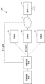
図1(システム全体図)に示すように、第1の実施形態に係る状態監視システム100は、状態監視装置1、移動体2および保守サーバ3を備える。状態監視装置1は、監視対象機器(例えば、蓄電池システム)の内部または外部に通信可能に接続され、監視対象機器の運転状態を監視する。状態監視装置1は、通常はネットワーク4(例えばインターネット)に接続されており、当該ネットワーク4を介して、監視対象機器の運転状態を運転情報として保守サーバ3に送信する(これを第1の通信とも称呼する)。
(状態監視システム)
図1(システム全体図)に示すように、第1の実施形態に係る状態監視システム100は、状態監視装置1、移動体2および保守サーバ3を備える。状態監視装置1は、監視対象機器(例えば、蓄電池システム)の内部または外部に通信可能に接続され、監視対象機器の運転状態を監視する。状態監視装置1は、通常はネットワーク4(例えばインターネット)に接続されており、当該ネットワーク4を介して、監視対象機器の運転状態を運転情報として保守サーバ3に送信する(これを第1の通信とも称呼する)。
何らかの異常が発生して状態監視装置1とネットワーク4との通信接続が切断され、状態監視装置1と保守サーバ3との間の通信が途絶えた場合、状態監視装置1は、移動体2に無線通信接続を依頼する。移動体2は、移動と無線通信とが可能な端末であり、例えば、飛行系であれば無線通信機能を備えたドローン、陸上系であれば無線通信機能を備えた小型車などがこれに該当する。移動体2は、無線通信を介して受信した状態監視装置の運転情報を、ネットワーク4を介して保守サーバ3に送信する(これを第2の通信とも称呼する)。常に通信が不安定な環境の場合、移動体2は所定間隔で状態監視装置1の周囲を移動(巡回)するように設定されていても良い。
尚、移動体2は上記に限定されず、例えば、無線通信機能を備えているスマートフォンやパーソナルコンピュータであってもよい。この場合、例えばGPS(Global Positioning System)を用いて状態監視装置1と無線通信可能な場所に存在するスマートフォンやパーソナルコンピュータを検出し、検出されたスマートフォンやパーソナルコンピュータに対し、例えばテザリング機能を用いて対象機器の運転情報をネットワーク4に送信してくれるように依頼する。
保守サーバ3は、状態監視装置1側から受信する運転情報を解析し、監視対象機器の運転状態を分析する。尚、状態監視装置1と保守サーバ3との間の通信が途絶えた場合、状態監視装置1のみならず、保守サーバ3もこれを検知し、移動体2に、状態監視装置1との間で無線通信が可能な位置に移動して無線通信を接続するように要求しても良い。保守サーバ3は、クラウド環境に作られたサーバ(クラウドサーバ)であってもよい。
尚、ネットワーク4および移動体2が提供する無線通信は、どのような種類の通信であっても良い。例えば、NFC(Near-field communication)といった短距離無線、Bluetooth(登録商標)といった無線PAN(Personal Area Network)、Wi-Fi(Wireless Fidelity;登録商標)といった無線LAN(Local Area Network)、WiMaxといった無線MAN(Metropolitan Area Network)である。尚、移動体2は複数種類の無線通信機能を搭載していても良い。例えば、移動体2が、無線LAN、無線PANおよび近距離無線の3つの通信機能を備えているとする。この場合、移動体2と状態監視装置1との間で無線LANを介しての通信が不安定な場合に、移動体2は状態監視装置1により近い位置に自らを移動させ、無線PANまたは近距離無線を介して、状態監視装置1から運転情報を取得する。運転情報の取得後、移動体2はネットワーク4と無線LANまたは無線MANを介して通信可能な位置に自らを移動させ、取得した運転情報を保守サーバ3側に送信する。
次に、各構成要素について詳細に説明する。
(状態監視装置)
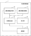
状態監視装置1は、図2に示すように、運転情報収集部11、運転情報記憶部12、故障検出部13、表示部14および通信部15を備える。
状態監視装置1は、図2に示すように、運転情報収集部11、運転情報記憶部12、故障検出部13、表示部14および通信部15を備える。
運転情報収集部11は、監視対象機器に取り付けられるセンサから、監視対象機器の運転情報(運転状態情報および故障情報)を収集する。
運転情報記憶部12は、運転情報を格納する。運転情報には、運転状態情報および故障情報が含まれる。運転状態情報とは、例えば、監視対象機器のリアルタイムの運転ログである。故障情報とは、例えば、エラーコードおよび故障重症度である。この他、運転情報には、監視対象機器ID(IDentifier)、タイムスタンプ、保守サーバアドレスが含まれる。
運転ログは、イベントログ、設定値ログおよび計測値ログを含む。イベントログは、何らかのイベントが監視対象機器内で発生したことを示すログである。設定値ログは、運転のスケジュールが設定されている場合に、監視対象機器に設定されている設定値を示すログである。計測値ログは、監視対象機器のリアルタイムの運転ログであり、例えば、蓄電池システムであれば、電圧、電流および温度の計測値がこれに該当する。
エラーコードは、例えば、監視対象機器内でエラーが発生した場合に、当該エラーの種類を特定するためのコードまたは数文字列である。
故障重症度とは、故障の程度を示す情報であり、例えば、「重症」、「軽症」、「不明」の3ランクに分けられる。例えば蓄電池システムであると、「重症」とは、過充電、過放電、過電流などの電池の安全性に関わる致命的な障害である。この場合、保守員はシステムを直ちに停止する必要がある。「軽症」とは、例えばパワーコンディショナーのリレー故障、ユニットとの無通信の検出結果に基づくユニット故障であり、自動復旧が必要な障害である。この場合、遠隔操作を介しまたは自律的に当該ユニットのリセットを試みる必要がある。「不明」とは、系統瞬時過電圧、系統電力異常などの、直接的な故障の原因は不明ではあるが、システムの動作を止めて一時待機する必要がある障害である。この場合、一定期間待つことで、故障原因の外因が解消されることがある。尚、一定期間待っても故障が解消されない場合は、故障重症度が「軽症」や「重症」に上がるように設定しても良い。尚、故障重症度の内容、ランク数は上記に限定されるものではなく、監視対象機器の動作状況に応じて変更可能である。
監視対象機器IDは、監視対象機器をユニークに識別するための識別子である。
タイムスタンプは、運転情報が生成された時刻を示すスタンプである。
保守サーバアドレスは、保守サーバ3の宛先アドレスである。
故障検出部13は、運転情報収集部11から送られる現在の運転情報および運転情報記憶部12から取得する過去の運転情報に基づき、監視対象機器の故障の検出および故障重症度の判定を行う。
表示部14は、故障の有無、故障重症度、移動体2への情報送信の有無のうちの少なくとも1つを表示するための表示装置であり、例えば、ディスプレイ装置、ランプがこれに当たる。
通信部15は、ネットワーク4を介し、保守サーバ3と通信を実行する。通信部15は、通信正常時に、監視対象機器の運転情報を保守サーバ3へ送信するための第1の通信回線と、第1の通信回線が通信不可能な場合に移動体2が提供する無線通信を介して保守サーバ3へ運転情報を送信するための第2の通信回線とを使用可能である。通信部15は、何らかの原因で第1の通信回線を介した通信が不可能なことを検知すると、移動体2を探索し、移動体2が提供する無線通信への接続を要求する。更に、通信部15は、移動体2に対して通信切断に関する情報(例えば、切断の位置および時間)を要求してもよい。
通信部15は、第2の通信回線を使用して通信する場合、第2の通信回線における通信品質を測定し、測定結果を基に送信すべき運転情報を選択してもよい。即ち、通信部15は、通信疎通時における移動体2との通信品質(通信速度、通信ロスなど)の測定などを行い、当該通信品質を考慮して、送信する運転情報のデータ量を調整してもよい。例えば、通信品質が良ければ多くのデータ量(運転状態情報など)の送信を行い、通信品質が悪ければ少量の重要であろうデータ(故障情報など)を送信する。尚、通信品質は、状態監視装置1と移動体2との間の通信品質、および、移動体2と保守サーバ3との間の通信品質を含む。即ち、状態監視装置1と移動体2との間および移動体2と保守サーバ3との間の通信品質が一定以上である場合に状態監視装置1と保守サーバ3との間の通信が可能となるので、通信部15は両方の通信のバランスを考慮して送信データ量を決定する。これは通信品質が悪い方の通信がボトルネックとなり、結果、予定していたデータ量を予定時間内で送信できなくなることを防止するためである。
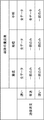
更に、通信部15は、通信速度と故障重症度とを考慮して送信するデータ量を調整してもよい。例えば、状態監視装置1は、図3に示すように、通信速度を表わす「速い」、「普通」、「遅い」を行とし、故障重症度を表わす「重症」、「軽症」、「不明」を列とした表内のセルに、各セルの状態において送信するデータ量が入力された表のデータを作成し、運転情報記憶部12に予め記憶しておく。通信部15は、この表のデータを基に、送信すべきデータ量を決定する。この表のデータは状態監視装置1と移動体2との間の通信について作成されても良いし、移動体2と保守サーバ3との間の通信について作成されても良い。
(移動体)
移動体2は、図4に示すように、運転情報選択部21、表示部22、通信部23および経路記憶部24を備える。
移動体2は、図4に示すように、運転情報選択部21、表示部22、通信部23および経路記憶部24を備える。
運転情報選択部21は、状態監視装置1から受信する運転情報のうち、保守サーバ3へ送信すべきデータを選択する。選択の際には、運転情報に含まれる故障重症度、移動体2と保守サーバ3との間の通信の安定度が考慮されてもよい。
表示部22は、故障した監視対象機器を識別する情報、当該監視対象機器を保守すべき保守サーバ3を識別する情報、故障重症度および保守サーバ3への情報送信の有無を表示するディスプレイまたはランプである。
通信部23は、運転情報選択部21によって選択された情報を、保守サーバ3側に対して送信する。通信部23は、状態監視装置1から受信する運転情報を、そのまま保守サーバ3へ転送してもよい。
経路記憶部24は、移動体2が移動する経路を格納する。移動する経路は予め設定されているものとする。更に、状態監視装置1または保守サーバ3から、通信部23を介して、移動する経路を受信しても良い。
移動体2が状態監視装置1側へ移動を開始するトリガは、例えば、予め定められた時間となった場合(この時間は周期的であっても良い)である。この他、第1の通信が不可能なことを検知した保守サーバ3または状態監視装置1から通信部23が、無線通信供給の要求を受信したことを、移動を開始するトリガとしてもよい。
(保守サーバ)
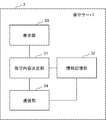
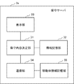
保守サーバ3は、図5に示すように、保守内容決定部31、情報記憶部32、表示部33および通信部34を備える。
保守サーバ3は、図5に示すように、保守内容決定部31、情報記憶部32、表示部33および通信部34を備える。
情報記憶部32は、これまで受信した上記の選択された情報、運転情報、および、当該運転情報を基に実行された保守情報の履歴を記憶する。
保守内容決定部31は、通信部34から受信する上記の選択された情報、情報記憶部32から取得する当該監視対象機器の過去の運転情報および過去の保守情報に基づき、今回の保守内容(保守情報)を決定する。決定された保守情報は、情報記憶部32に格納される。
表示部33は、運転情報に含まれる、故障の可能性の有る監視対象機器のID、故障の有無、故障重症度および保守情報を保守員に示すためのディスプレイまたはランプである。
通信部34は、選択された情報や運転情報を移動体2(通信疎通中であれば状態監視装置1)から受信する。更に通信部34は、保守情報を移動体2(通信疎通中であれば状態監視装置1)に送信する。
(状態監視システムの動作)
状態監視システム100の動作について説明する。状態監視システム100の動作には、大きく分けて「1.状態監視装置1と保守サーバ3との間で第1の通信が可能である時の動作」、「2.第1の通信が不可能である場合に、状態監視装置1と保守サーバ3との間で、移動体2を介して第2の通信を実行する時の動作」がある。2.は更に「(2-1)状態監視装置1から保守サーバ3へ、移動体2を介して、定期的に運転情報を送信するときの動作」、「(2-2)故障発生時に状態監視装置1から保守サーバ3へ、移動体2を介して、故障情報を送信するときの動作」、「(2-3)保守サーバ3から状態監視装置1へ、移動体2を介して、情報を送信するときの動作」がある。尚、(2-3)の動作は、スケジュール設定時やファームウェア更新時に、さらには故障発生時に、保守員が監視対象機器まで出向くことなく、通信を介して保守サーバ3が状態監視装置1に所望プログラムを設定、更新するための動作である。1.の動作については既存の通信技術にて実行できるため説明を省略する。以下、2.において状態監視システム100が実行する3つの動作について、フローチャートを参照して説明する。
状態監視システム100の動作について説明する。状態監視システム100の動作には、大きく分けて「1.状態監視装置1と保守サーバ3との間で第1の通信が可能である時の動作」、「2.第1の通信が不可能である場合に、状態監視装置1と保守サーバ3との間で、移動体2を介して第2の通信を実行する時の動作」がある。2.は更に「(2-1)状態監視装置1から保守サーバ3へ、移動体2を介して、定期的に運転情報を送信するときの動作」、「(2-2)故障発生時に状態監視装置1から保守サーバ3へ、移動体2を介して、故障情報を送信するときの動作」、「(2-3)保守サーバ3から状態監視装置1へ、移動体2を介して、情報を送信するときの動作」がある。尚、(2-3)の動作は、スケジュール設定時やファームウェア更新時に、さらには故障発生時に、保守員が監視対象機器まで出向くことなく、通信を介して保守サーバ3が状態監視装置1に所望プログラムを設定、更新するための動作である。1.の動作については既存の通信技術にて実行できるため説明を省略する。以下、2.において状態監視システム100が実行する3つの動作について、フローチャートを参照して説明する。
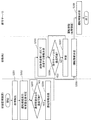
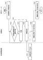
(2-1)状態監視装置1から保守サーバ3へ、移動体2を介して、定期的に運転情報(少なくとも運転状態情報を含む)を送信するときの動作について、図6のフローチャートを参照して説明する。尚、本動作は予め設定される時間間隔毎に繰り返し行われる。
先ずステップS101において、状態監視装置1の運転情報収集部11は、予め設定された所定間隔毎や何らかの異常発生をトリガとし、監視対象機器に取り付けられるセンサ機器から、監視対象機器の運転情報を収集し、運転情報記憶部12に格納する。通信部15は、運転情報記憶部12に新たな運転情報が格納されたことを移動体2に通知しても良い。
ステップS102において、予め設定された所定間隔毎に、移動体2は運転情報を集めるために担当となっている区域を、経路記憶部24に格納される経路を基に移動する。この移動により、移動体2の通信部23は、状態監視装置1と通信が可能であることを検出する。ステップS103において、移動体2の通信部23が、状態監視装置1と通信が可能であることを検出すると、ステップS104において、状態監視装置1に対し、無線通信を介して、運転情報の送信を要求する。
ステップS105において、当該要求を受信した状態監視装置1の通信部15は、運転情報記憶部12に格納される運転情報を取得し、無線通信を介して、移動体2に送信する。
ステップS106において、運転情報を取得した移動体2は、ネットワーク4を介して保守サーバ3と無線通信が可能であるかを判断する。無線通信可能と判断されると処理はステップS108へ進められ、無線通信不可能と判断されると処理はステップS107へ進められる。
ステップS107において、移動体2はネットワーク4を介して保守サーバ3と無線通信が可能である位置まで移動する。
ステップS108において、移動体2はネットワーク4を介して保守サーバ3に対し運転情報を送信する。
ステップS109において、保守サーバ3は、ネットワーク4を介し、運転情報を受信する。
以上で、(2-1)状態監視装置1から保守サーバ3へ、移動体2を介して、定期的に運転情報を送信するときの動作についての説明を終了する。
(2-2)故障発生時に状態監視装置1から保守サーバ3へ、移動体2を介して、運転情報(少なくとも故障情報を含む)を送信するときの動作について、図7のフローチャートを参照して説明する。
先ずステップS201において、状態監視装置1の故障検出部13は、運転情報収集部11から送られる現在の運転情報と、運転情報記憶部12から取得する過去の運転情報とを比較し、監視対象機器の故障を検出する。例えば、ある値が過去の値と比して急激に大きくなったまたは急激に小さくなったときに、故障検出部13はその値に関連する機器に故障が発生したと判断する。
ステップS202において、故障検出部13は、故障検出の判断結果およびその基となる運転情報を運転情報記憶部12に格納する。更に、故障検出部13は、故障検出の判断結果およびその基となる運転情報を基に、故障重症度を判定する。例えば、故障検出部13は、検出された故障が、上述した「重症」、「軽症」、「不明」の3ランクのいずれに当てはまるかを判断する。
ステップS203において、状態監視装置1の通信部15は、移動体2との通信が可能であるか検出する。通信可能であると検出されると、処理はステップS204へ進められる。通信不可能であると検出されると、通信部15は、移動体2との通信が可能となるまで検出を繰り返す。
ステップS204において、通信部15は、移動体2に対して故障重症度を含む運転情報を送信する。
ステップS205において、運転情報を受信した移動体2の運転情報選択部21は、運転情報に含まれる故障重症度を取得し、図3に示す表のデータを参照し、当該故障重要度に応じて保守サーバ3側へ送信する運転情報を選択する。例えば、移動体2の通信部23に、移動体2と保守サーバ3との間の通信速度を測定させ、通信速度が所定速度以上(速い)の場合には運転情報全てを送信し、通信速度が所定速度以下(遅い)の場合には運転情報の一部(運転状態情報のみ)を送信するようにしてもよい。
ステップS206において、通信部23は、ネットワーク4を介して保守サーバ3と無線通信が可能であるかを判断する。無線通信可能と判断されると処理はステップS208へ進められ、無線通信不可能と判断されると処理はステップS207へ進められる。
ステップS207において、移動体2はネットワーク4を介して保守サーバ3と無線通信が可能である位置まで移動する。
ステップS208において、移動体2はネットワーク4を介して保守サーバ3に対し運転情報を送信する。
ステップS209において、保守サーバ3は、ネットワーク4を介して、運転情報を受信する。
以上で、(2-2)故障発生時に状態監視装置1から保守サーバ3へ、移動体2を介して、運転情報(少なくとも故障情報を含む)を送信するときの動作についての説明を終了する。
(2-3)保守サーバ3から状態監視装置1へ、移動体2を介して、情報を送信するときの動作について、図8のフローチャートを参照して説明する。尚、準備として、保守サーバ3は、状態監視装置1と当該状態監視装置1を担当する移動体2との紐付けおよびこれらの通信アドレスを記憶しているものとする。また、保守サーバ3は状態監視装置1と直接通信が不可能であるものとする。
ステップS301において、保守サーバ3の通信部34は、状態監視装置1に紐付けられた移動体2に対して、状態監視装置1との接続要求と情報を送信する。この情報とは、初期設定の情報、状態監視装置1に不具合が発生した場合に当該状態監視装置1を更新するための情報である。初期設定するまたは更新する情報とは、例えば、ファームウェア情報、DR(Demand Response)スケジュールがある。またはこの情報とは、状態監視装置1から故障が検出されたことを伝える運転情報を受信した際に、保守内容決定部31が運転情報およびこれに含まれる故障重症度を基に決定した、当該保守内容を実行するための情報であってもよい。
ステップS302において、移動体2の通信部23は、状態監視装置1との無線通信が可能であるかを検出する。無線通信可能と判断されると処理はステップS304へ進められ、無線通信不可能と判断されると処理はステップS303へ進められる。
ステップS303において、移動体2は状態監視装置1と無線通信が可能である位置まで移動する。
ステップS304において、移動体2は無線通信を介して状態監視装置1に対し情報を送信する。
ステップS305において、状態監視装置1の通信部15は、情報の受信完了を示す応答メッセージを移動体2に対し無線通信を介して送信する。ステップS306において、当該応答メッセージを受信した移動体2の通信部23は、情報伝達が完了したことを示す応答メッセージを保守サーバ3に対しネットワーク4を介して送信する。
ステップS307において、保守サーバ3は、ネットワーク4を介して当該応答メッセージを受信する。
以上で、保守サーバ3から状態監視装置1へ、移動体2を介して、情報を送信するときの動作についての説明を終了する。
(第1の実施形態の効果)
本発明の第1の実施形態にかかる状態監視装置1によると、遠隔の、通信環境の悪い場所に配置される監視対象機器の状態監視情報を、保守員側に確実に届けることができる。この理由は、状態監視装置1が、監視対象機器の運転情報をサーバ装置へ送信するための第1の通信回線が通信不可能な場合に、移動体2が提供する無線通信を介して(第2の通信回線)、保守サーバ3へ運転情報を送信するからである。
本発明の第1の実施形態にかかる状態監視装置1によると、遠隔の、通信環境の悪い場所に配置される監視対象機器の状態監視情報を、保守員側に確実に届けることができる。この理由は、状態監視装置1が、監視対象機器の運転情報をサーバ装置へ送信するための第1の通信回線が通信不可能な場合に、移動体2が提供する無線通信を介して(第2の通信回線)、保守サーバ3へ運転情報を送信するからである。
<第2の実施形態>
第1の実施形態においては、移動体2は1つであったが、これは複数存在してもよい。即ち、複数の移動体2が備える無線通信機能を介して、状態監視装置1と保守サーバ3との間を通信接続しても良い。このように複数の移動体2同士が通信することにより、移動体2が移動する距離を縮めることができ、結果、より早く情報を伝達することができる。以下、第2の実施形態においては、複数の移動体2を用いて情報を伝達させる状態監視システム200について説明する。
第1の実施形態においては、移動体2は1つであったが、これは複数存在してもよい。即ち、複数の移動体2が備える無線通信機能を介して、状態監視装置1と保守サーバ3との間を通信接続しても良い。このように複数の移動体2同士が通信することにより、移動体2が移動する距離を縮めることができ、結果、より早く情報を伝達することができる。以下、第2の実施形態においては、複数の移動体2を用いて情報を伝達させる状態監視システム200について説明する。
(状態監視システム)
図9(システム全体図)に示すように、第2の実施形態に係る状態監視システム200は、状態監視装置1a、複数の移動体2A、2Bおよび2C(以下2A-2Cと記載)および保守サーバ3aを備える。複数の移動体2A-2Cは互いに通信可能である。例えば、複数の移動体2A-2Cはアドホックネットワークを構築し、アドホックモードで直接通信を実行する。
図9(システム全体図)に示すように、第2の実施形態に係る状態監視システム200は、状態監視装置1a、複数の移動体2A、2Bおよび2C(以下2A-2Cと記載)および保守サーバ3aを備える。複数の移動体2A-2Cは互いに通信可能である。例えば、複数の移動体2A-2Cはアドホックネットワークを構築し、アドホックモードで直接通信を実行する。
1つの巡回区域は、複数の移動体2A-2Cによって巡回されてよい。これは、同一ルートを巡回する移動体2Aと移動体2Bとの巡回開始時刻をずらしても良い。例えば、一巡回に2分かかる区域において、移動体2Aの巡回開始1分後に移動体2Bを巡回開始させてもよい。これにより、巡回区域に存在する状態監視装置1aは、移動体2A-2Cと毎分通信可能となる。この他、巡回区域における移動体2A-2Cの配置を直接通信可能に調整し、状態監視装置1aが送信する運転情報を、移動体2A-2C同士が直接通信して、保守サーバ3に届けても良い。
図9においては、監視対象機器およびこれに接続される状態監視装置1aは1セットであるが、これは複数存在しても良い。この場合、複数の移動体2A-2Cは、複数の上記セットを巡回するように移動する。
図10に示すように、状態監視装置1aは、運転情報収集部11、運転情報記憶部12、故障検出部13、表示部14、通信部15および運転情報選択部16を備える。運転情報選択部16は、通信部15を介して受信する通信可能な移動体2A-2C(複数存在しても良い)毎の通信品質(通信速度、通信ロスなど)の測定を行う。運転情報選択部16は、当該通信品質を考慮して、運転情報記憶部12に格納される、送信すべき運転情報のデータ量を調整する。例えば、通信品質が良い移動体に対して多くのデータ(運転情報)を送信させ、通信品質が悪い移動体に対して少量のデータ(運転情報)を送信させる。一般的に、運転ログ(運転状態情報)は大きなデータとなるので、運転情報選択部16は、当該運転ログを通信品質が良い移動体に割り当てて送信するようにする。その他の各部の機能は第1の実施形態と同様である。
図11に示すように、移動体2A-2Cは、運転情報選択部21、表示部22および通信部23aを備える。通信部23aは、他の移動体との通信(例えばアドホック通信)が可能である。その他の機能は第1の実施形態と同様である。
図12に示すように、保守サーバ3aは、情報記憶部32、保守内容決定部31、表示部33、通信部34および移動体情報記憶部35を備える。移動体情報記憶部35は、移動体2A-2Cに関する情報を格納する。移動体2A-2Cに関する情報とは、例えば、各移動体2A-2Cを識別可能な情報、各移動体2A-2Cとの通信品質の履歴、各移動体2A-2Cに割り当てられた巡回地域、当該巡回地域に存在する状態監視装置1a、状態監視装置1aとの通信切断履歴、通信切断となった状態監視装置1aを識別する情報、および、通信不可能であった時間などである。その他の各部の機能は第1の実施形態と同様である。
(状態監視システムの動作)
状態監視システム200の動作について説明する。状態監視システム200の動作には、大きく分けて「1.状態監視装置1aと保守サーバ3aとの間で第1の通信が可能である時の動作」、「2.第1の通信が不可能である場合に、状態監視装置1aと保守サーバ3aとの間で、移動体2A、2Bを介して第2の通信を行う時の動作」がある。2.は更に「(2-4)状態監視装置1aの運転情報を複数の移動体2A、2Bを介して保守サーバ3aへ送信させる際に、移動体2A、2B毎の通信品質に応じて送信すべきデータ量を調整して、運転情報のデータを各々の移動体2A、2Bが送信するときの動作」、「(2-5)状態監視装置1aの運転情報を複数の移動体2A、2Bを介して保守サーバ3aへ送信させる際に、移動体2A、2B間で運転情報を転送して送信するときの動作」がある。1.の動作については既存の通信技術にて実行できるため説明を省略する。以下、2.において状態監視システム200が実行する2つの動作について、フローチャートを参照して説明する。
状態監視システム200の動作について説明する。状態監視システム200の動作には、大きく分けて「1.状態監視装置1aと保守サーバ3aとの間で第1の通信が可能である時の動作」、「2.第1の通信が不可能である場合に、状態監視装置1aと保守サーバ3aとの間で、移動体2A、2Bを介して第2の通信を行う時の動作」がある。2.は更に「(2-4)状態監視装置1aの運転情報を複数の移動体2A、2Bを介して保守サーバ3aへ送信させる際に、移動体2A、2B毎の通信品質に応じて送信すべきデータ量を調整して、運転情報のデータを各々の移動体2A、2Bが送信するときの動作」、「(2-5)状態監視装置1aの運転情報を複数の移動体2A、2Bを介して保守サーバ3aへ送信させる際に、移動体2A、2B間で運転情報を転送して送信するときの動作」がある。1.の動作については既存の通信技術にて実行できるため説明を省略する。以下、2.において状態監視システム200が実行する2つの動作について、フローチャートを参照して説明する。
(2-4)状態監視装置1aの運転情報を複数の移動体2A、2Bを介して保守サーバ3aへ送信させる際に、移動体2A、2B毎の通信品質に応じて送信すべきデータ量を調整して、運転情報のデータを各々の移動体2A、2Bが送信するときの動作について、図13のフローチャートを参照して説明する。
先ずステップS401において、状態監視装置1aの通信部15は、運転情報を、移動体2A、2Bが提供する無線通信を介して、移動体2A、2Bへ送信する。具体的に、状態監視装置1aの運転情報収集部11が監視対象機器の運転情報を収集して運転情報記憶部12に格納する。通信部15は、所定間隔毎、または、移動体2A、2Bから送信される送信要求をトリガとし、運転情報記憶部12に格納される運転情報を、無線通信を介して、移動体2A、2Bへ送信する。移動体2A、2Bの各々は各自でこの運転情報を一時保存する。
ステップS402において、保守サーバ3aが移動体2A、2Bに対し、通信品質を考慮して、運転情報の送信を要求する。通信品質の考慮においては、例えば、移動体情報記憶部35に格納される各移動体2A、2Bとの通信品質の履歴を基に判断する。例えば、通信品質の履歴において、保守サーバ3aと移動体2Aとの間の通信品質は良く、保守サーバ3aと移動体2Bとの間の通信品質は悪い場合、移動体2Aに対しては運転情報全て(運転ログを含む)を送信するように依頼し、移動体Bに対しては一部(少なくとも故障情報を含む)の運転情報を送信するように依頼する。この他、保守サーバ3aの通信部34が、運転情報の送信要求時において、移動体2A、2Bとの間での通信品質を測定し、当該測定結果を基に通信品質を判断し、各移動体2A、2Bに送信依頼する運転情報の内容を決定しても良い。
ステップS403において、保守サーバ3aからの運転情報の送信要求を移動体2Bは受信する。移動体2Bは、送信要求された運転情報(この場合、一部の運転情報)を一時保存する運転情報から選択し、保守サーバ3aに対しネットワーク4を介して送信する。
ステップS404において、保守サーバ3aからの運転情報の送信要求を移動体2Aは受信する。移動体2Aは、送信要求された運転情報(この場合、全ての運転情報)を一時保存する運転情報から取得し、保守サーバ3aに対しネットワーク4を介して送信する。
以上で、状態監視装置1aの運転情報を複数の移動体2A、2Bを介して保守サーバ3aへ送信させる際に、移動体2A、2B毎の通信品質に応じて送信すべきデータ量を調整して、運転情報のデータを各々の移動体2A、2Bが送信するときの動作についての説明を終了する。
(2-5)状態監視装置1aの運転情報を複数の移動体2A、2Bを介して保守サーバ3aへ送信させる際に、移動体2A、2B間で運転情報を転送して送信するときの動作について、図14のフローチャートを参照して説明する。
ステップS501において、状態監視装置1aの通信部15は、運転情報を、移動体2A、2Bが提供する無線通信を介して、移動体2A、2Bへ送信する。移動体2A、2Bの各々は各自でこの運転情報を一時保存する。この際、状態監視装置1aと移動体2A、2Bとの間の通信品質については考慮していない。尚、状態監視装置1aと移動体2Aとの間の通信品質は良く、状態監視装置1aと移動体2Bとの間の通信品質は悪いことを前提に、以下の説明を行う。
ステップS502において、保守サーバ3aが移動体2A、2Bに対し、運転情報の送信を要求する。この際、保守サーバ3a側では自らと移動体2A、2B間の通信品質の良し悪しについては考慮しない。この運転情報の送信要求を受信すると、複数の移動体2A、2Bの通信部23aは、互いに直接無線通信を開始する。例えば、通信部23aはアドホックモードに切り替え、アドホックネットワークを構築する。
ステップS503において、移動体2Aは一時保存する運転情報を移動体2Bに対して送信する。具体的には、複数の移動体2A、2Bの通信部23aは、アドホックネットワーク内において状態監視装置1aと通信品質が最も良好な移動体(図14では移動体2A)と、保守サーバ3aと通信品質が最も良好な移動体(図14では移動体2B)とを検出する。さらに当該移動体2Aに、自らが一時保存する運転情報を、最も保守サーバ3a側と通信品質が良好な移動体2Bに対して送信させる。この送信はアドホック通信で行われる。
ステップS504において、移動体2Bは受信した運転情報を、ネットワーク4を介して、保守サーバ3aに対して送信する。
以上で、状態監視装置1aの運転情報を複数の移動体2A、2Bを介して保守サーバ3aへ送信させる際に、移動体2A、2B間で運転情報を転送して送信するときの動作の説明を終了する。
(第2の実施形態の効果)
本発明の第2の実施形態にかかる状態監視装置1aによると、遠隔の、通信環境の悪い場所に配置される監視対象機器の状態監視情報を保守員側に確実に、第1の実施形態よりも素早く、届けることができる。この理由は、状態監視装置1aが、監視対象機器の運転情報をサーバ装置へ送信するための第1の通信回線が通信不可能な場合に、複数の移動体2A-2Cが提供する無線通信を介して(第2の通信回線)、保守サーバ3aへ運転情報を送信するからである。具体的には、移動体2A-2Cの各々が移動する距離を縮めることができるため、移動時間が短縮でき、より早く情報を伝達することができる。
本発明の第2の実施形態にかかる状態監視装置1aによると、遠隔の、通信環境の悪い場所に配置される監視対象機器の状態監視情報を保守員側に確実に、第1の実施形態よりも素早く、届けることができる。この理由は、状態監視装置1aが、監視対象機器の運転情報をサーバ装置へ送信するための第1の通信回線が通信不可能な場合に、複数の移動体2A-2Cが提供する無線通信を介して(第2の通信回線)、保守サーバ3aへ運転情報を送信するからである。具体的には、移動体2A-2Cの各々が移動する距離を縮めることができるため、移動時間が短縮でき、より早く情報を伝達することができる。
<第3の実施形態>
本発明の第3の実施形態にかかる状態監視装置300は、図15に示すように、通信部301を備える。通信部301は、監視する対象機器の運転情報をサーバ装置へ送信するための第1の通信回線と、当該第1の通信回線が通信不可能な場合に移動体が提供する無線通信を介してサーバ装置へ運転情報を送信するための第2の通信回線と、を使用して通信する。
本発明の第3の実施形態にかかる状態監視装置300は、図15に示すように、通信部301を備える。通信部301は、監視する対象機器の運転情報をサーバ装置へ送信するための第1の通信回線と、当該第1の通信回線が通信不可能な場合に移動体が提供する無線通信を介してサーバ装置へ運転情報を送信するための第2の通信回線と、を使用して通信する。
本発明の第3の実施形態によると、遠隔の、通信環境の悪い場所に配置される監視対象機器の状態監視情報を保守員側に確実に届けることができる。この理由は、通信部301が、当該第1の通信回線が通信不可能な場合に移動体が提供する無線通信を介してサーバ装置へ運転情報を送信するためである。
(情報処理装置)
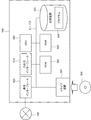
上述した本発明の各実施形態において、図1等に示す状態監視システムの各部(状態監視装置、移動体、保守サーバ)の構成要素の一部又は全部は、例えば図16に示すような情報処理装置500とプログラムとの任意の組み合わせを用いて実現することも可能である。情報処理装置500は、一例として、以下のような構成を含む。
上述した本発明の各実施形態において、図1等に示す状態監視システムの各部(状態監視装置、移動体、保守サーバ)の構成要素の一部又は全部は、例えば図16に示すような情報処理装置500とプログラムとの任意の組み合わせを用いて実現することも可能である。情報処理装置500は、一例として、以下のような構成を含む。
・CPU(Central Processing Unit)501
・ROM(Read Only Memory)502
・RAM(Random Access Memory)503
・プログラム504および他のデータを格納する記憶装置505
・記録媒体506の読み書きを行うドライブ装置507
・通信ネットワーク509と接続する通信インターフェース508
・データの入出力を行う入出力インターフェース510
・各構成要素を接続するバス511
本願の各実施形態における状態監視システムの各構成要素は、これらの機能を実現するプログラム504をCPU501が取得して実行することで実現される。状態監視システム各部の構成要素の機能を実現するプログラム504は、例えば、予め記憶装置505やRAM503に格納されており、必要に応じてCPU501が読み出す。なお、プログラム504は、通信ネットワーク509を介してCPU501に供給されてもよいし、予め記録媒体506に格納されており、ドライブ装置507が当該プログラムを読み出してCPU501に供給してもよい。
・ROM(Read Only Memory)502
・RAM(Random Access Memory)503
・プログラム504および他のデータを格納する記憶装置505
・記録媒体506の読み書きを行うドライブ装置507
・通信ネットワーク509と接続する通信インターフェース508
・データの入出力を行う入出力インターフェース510
・各構成要素を接続するバス511
本願の各実施形態における状態監視システムの各構成要素は、これらの機能を実現するプログラム504をCPU501が取得して実行することで実現される。状態監視システム各部の構成要素の機能を実現するプログラム504は、例えば、予め記憶装置505やRAM503に格納されており、必要に応じてCPU501が読み出す。なお、プログラム504は、通信ネットワーク509を介してCPU501に供給されてもよいし、予め記録媒体506に格納されており、ドライブ装置507が当該プログラムを読み出してCPU501に供給してもよい。
各装置の実現方法には、様々な変形例がある。例えば、状態監視システムの各部の構成要素は、構成要素毎にそれぞれ別個の情報処理装置とプログラムとの任意の組み合わせにより実現されてもよい。また、状態監視システムが備える複数の構成要素が、一つの情報処理装置500とプログラムとの任意の組み合わせにより実現されてもよい。
また、状態監視システムの各部の構成要素の一部又は全部は、その他の汎用または専用の回路、プロセッサ等やこれらの組み合わせによって実現される。これらは、単一のチップによって構成されてもよいし、バスを介して接続される複数のチップによって構成されてもよい。
状態監視システムの各部の構成要素の一部又は全部は、上述した回路等とプログラムとの組み合わせによって実現されてもよい。
状態監視システムの各部の構成要素の一部又は全部が複数の情報処理装置や回路等により実現される場合には、複数の情報処理装置や回路等は、集中配置されてもよいし、分散配置されてもよい。例えば、情報処理装置や回路等は、クライアントアンドサーバシステム、クラウドコンピューティングシステム等、各々が通信ネットワークを介して接続される形態として実現されてもよい。
以上、本実施形態を参照して本願発明を説明したが、本願発明は上記実施形態に限定されるものではない。本願発明の構成や詳細には、本願発明のスコープ内で当業者が理解し得る様々な変更をすることができる。
この出願は2018年3月19日に出願された日本出願特願2018-051208を基礎とする優先権を主張し、その開示の全てをここに取り込む。
1 状態監視装置
1a 状態監視装置
2 移動体
2A、2B、2C 移動体
3 保守サーバ
3a 保守サーバ
4 ネットワーク
11 運転情報収集部
12 運転情報記憶部
13 故障検出部
14 表示部
15 通信部
16 運転情報選択部
21 運転情報選択部
22 表示部
23 通信部
23a 通信部
31 保守内容決定部
32 情報記憶部
33 表示部
34 通信部
35 移動体情報記憶部
100 状態監視システム
200 状態監視システム
300 状態監視装置
301 通信部
500 情報処理装置
501 CPU
502 ROM
503 RAM
504 プログラム
505 記憶装置
506 記録媒体
507 ドライブ装置
508 通信インターフェース
509 通信ネットワーク
510 入出力インターフェース
511 バス
1a 状態監視装置
2 移動体
2A、2B、2C 移動体
3 保守サーバ
3a 保守サーバ
4 ネットワーク
11 運転情報収集部
12 運転情報記憶部
13 故障検出部
14 表示部
15 通信部
16 運転情報選択部
21 運転情報選択部
22 表示部
23 通信部
23a 通信部
31 保守内容決定部
32 情報記憶部
33 表示部
34 通信部
35 移動体情報記憶部
100 状態監視システム
200 状態監視システム
300 状態監視装置
301 通信部
500 情報処理装置
501 CPU
502 ROM
503 RAM
504 プログラム
505 記憶装置
506 記録媒体
507 ドライブ装置
508 通信インターフェース
509 通信ネットワーク
510 入出力インターフェース
511 バス
Claims (10)
- 監視する対象機器の運転情報をサーバ装置へ送信するための第1の通信回線と、前記第1の通信回線が通信不可能な場合に移動体が提供する無線通信を介して前記サーバ装置へ前記運転情報を送信するための第2の通信回線と、
を使用して通信する通信手段を備える
状態監視装置。 - 前記通信手段は、前記第1の通信回線が通信不可能なことを検知すると、前記移動体に対し、前記無線通信への接続を要求する
請求項1に記載の状態監視装置。 - 前記運転情報は、前記対象機器の運転状態情報および前記対象機器の故障情報を含み、
前記通信手段は、前記第2の通信回線を使用して通信する場合、前記第2の通信回線における通信品質を測定し、測定結果を基に送信すべき前記運転状態情報または前記故障情報を選択する
請求項1または請求項2に記載の状態監視装置。 - 前記通信品質は、前記自装置と前記移動体との間の通信品質、および、前記移動体と前記サーバ装置との間の通信品質の少なくとも片方を含む
請求項1乃至請求項3のいずれかに記載の状態監視装置。 - 前記移動体は複数存在し、
複数の前記移動体の各々の通信品質を測定し、測定された通信品質を基に、前記運転情報の送信を依頼すべき1つ以上の移動体と、当該1つ以上の移動体の各々に送信すべき前記運転情報の内容を選択する
運転情報選択手段
を更に備える請求項1乃至請求項4のいずれかに記載の状態監視装置。 - 請求項1乃至請求項5のいずれかに記載の状態監視装置と、
前記状態監視装置が監視する対象機器の運転情報を第1の通信回線を介して送信不可能な場合に、前記状態監視装置との間で無線通信可能な位置まで移動して無線通信を接続する移動体と、
前記無線通信を用いる第2の通信回線を介して、自装置と前記状態監視装置との間で前記運転情報を受信するサーバ装置
とを備える状態監視システム。 - 前記移動体は、前記状態監視装置が監視する対象機器の運転情報が第1の通信回線を介して送信不可能な場合に、前記サーバ装置と通信可能な位置まで移動して前記運転情報を送信する
請求項6に記載の状態監視システム。 - 複数の前記移動体の各々は互いに直接通信可能であり、前記サーバ装置から前記状態監視装置との間で第1の通信回線における通信不可能な場合に、
前記状態監視装置から無線通信を介して前記運転情報を受信する第1の移動体と、第1の移動体が受信する前記運転情報を前記直接通信を介して受信し、当該受信した前記運転情報を、通信を介して前記サーバ装置へ送信する第2の移動体、とを用いる第2の通信回線において通信を行う
請求項6または請求項7に記載の状態監視システム。 - 監視する対象機器の運転情報をサーバ装置へ送信するための第1の通信回線と、前記第1の通信回線が通信不可能な場合に移動体が提供する無線通信を介して前記サーバ装置へ前記運転情報を送信するための第2の通信回線と、
を使用して通信することを備える
状態監視方法。 - 監視する対象機器の運転情報をサーバ装置へ送信するための第1の通信回線と、前記第1の通信回線が通信不可能な場合に、移動体が提供する無線通信を介して前記サーバ装置へ前記運転情報を送信するための第2の通信回線と、
を使用して通信することを
コンピュータに実現させるための状態監視プログラムを格納する記録媒体。
Priority Applications (3)
| Application Number | Priority Date | Filing Date | Title |
|---|---|---|---|
| US16/965,928 US11563656B2 (en) | 2018-03-19 | 2019-03-13 | State monitoring device, state monitoring system, and state monitoring method |
| EP19770987.6A EP3771192A4 (en) | 2018-03-19 | 2019-03-13 | State monitoring device, state monitoring system, state monitoring method, and recording medium |
| JP2020508259A JP6923071B2 (ja) | 2018-03-19 | 2019-03-13 | 状態監視装置、状態監視システム、状態監視方法および状態管理プログラム |
Applications Claiming Priority (2)
| Application Number | Priority Date | Filing Date | Title |
|---|---|---|---|
| JP2018-051208 | 2018-03-19 | ||
| JP2018051208 | 2018-03-19 |
Publications (1)
| Publication Number | Publication Date |
|---|---|
| WO2019181674A1 true WO2019181674A1 (ja) | 2019-09-26 |
Family
ID=67986407
Family Applications (1)
| Application Number | Title | Priority Date | Filing Date |
|---|---|---|---|
| PCT/JP2019/010167 Ceased WO2019181674A1 (ja) | 2018-03-19 | 2019-03-13 | 状態監視装置、状態監視システム、状態監視方法および記録媒体 |
Country Status (4)
| Country | Link |
|---|---|
| US (1) | US11563656B2 (ja) |
| EP (1) | EP3771192A4 (ja) |
| JP (1) | JP6923071B2 (ja) |
| WO (1) | WO2019181674A1 (ja) |
Cited By (6)
| Publication number | Priority date | Publication date | Assignee | Title |
|---|---|---|---|---|
| JP2021100224A (ja) * | 2019-12-23 | 2021-07-01 | 株式会社ノーリツ | 給湯装置、サーバ、給湯システムおよびプログラム |
| JP2021144693A (ja) * | 2020-03-12 | 2021-09-24 | キヤノン株式会社 | 情報処理装置、その制御方法及びプログラム |
| JP2024000731A (ja) * | 2022-06-21 | 2024-01-09 | パナソニックIpマネジメント株式会社 | 情報端末、サーバシステム、情報処理方法、及びプログラム |
| WO2024162268A1 (ja) * | 2023-01-30 | 2024-08-08 | 川崎重工業株式会社 | 飛行支援システム、方法及びプログラム |
| JP2024154960A (ja) * | 2023-04-20 | 2024-10-31 | 株式会社クボタ | 作業機の稼働情報管理システム |
| WO2025004671A1 (ja) * | 2023-06-29 | 2025-01-02 | 株式会社デンソー | 電池監視システム、電池監視システムの送信機、電池監視システムの受信機、無線通信プログラム、及び無線通信方法 |
Families Citing this family (3)
| Publication number | Priority date | Publication date | Assignee | Title |
|---|---|---|---|---|
| JP7287167B2 (ja) * | 2019-07-30 | 2023-06-06 | トヨタ自動車株式会社 | 車載通信装置 |
| CN114268562B (zh) * | 2021-11-01 | 2024-07-26 | 贵州电网有限责任公司 | 芯片化继电保护的传输链路检测装置、系统和方法 |
| CN120857231A (zh) * | 2024-04-25 | 2025-10-28 | 博通集成电路(上海)股份有限公司 | 操作模式控制管理方法及其系统 |
Citations (11)
| Publication number | Priority date | Publication date | Assignee | Title |
|---|---|---|---|---|
| JPH09238199A (ja) * | 1996-02-29 | 1997-09-09 | Kyocera Corp | 遠隔監視装置 |
| JP2002198887A (ja) * | 2000-12-25 | 2002-07-12 | Shin Caterpillar Mitsubishi Ltd | 作業機械用の通信制御方法およびその装置 |
| JP2006165627A (ja) * | 2004-12-02 | 2006-06-22 | Sharp Corp | 電気機器の遠隔監視システム |
| JP2006275303A (ja) | 2005-03-28 | 2006-10-12 | Daikin Ind Ltd | 異常検知システム |
| JP2017054202A (ja) | 2015-09-07 | 2017-03-16 | パナソニックIpマネジメント株式会社 | 情報処理装置、不具合原因特定方法及びプログラム |
| JP2017069803A (ja) * | 2015-09-30 | 2017-04-06 | ソフトバンク株式会社 | 安否確認方法、小型基地局及びドローン |
| JP2017155557A (ja) * | 2016-03-04 | 2017-09-07 | コベルコ建機株式会社 | 建設機械、建設機械から稼働データを取得するための携帯情報端末、建設機械の情報通信システム、及び携帯情報端末に実装されるプログラム |
| WO2017158706A1 (ja) | 2016-03-14 | 2017-09-21 | 株式会社 東芝 | 蓄電池評価装置、蓄電システムおよび蓄電池評価方法 |
| JP2017169093A (ja) * | 2016-03-17 | 2017-09-21 | パナソニック インテレクチュアル プロパティ コーポレーション オブ アメリカPanasonic Intellectual Property Corporation of America | 通信方法、通信装置及び通信システム |
| JP2017195493A (ja) * | 2016-04-20 | 2017-10-26 | 日本電気株式会社 | 移動通信システム |
| JP2018051208A (ja) | 2016-09-30 | 2018-04-05 | 株式会社ニデック | 眼科情報処理装置、眼科情報処理プログラム、および眼科情報処理システム |
Family Cites Families (13)
| Publication number | Priority date | Publication date | Assignee | Title |
|---|---|---|---|---|
| US7865584B2 (en) * | 2006-06-20 | 2011-01-04 | Alcatel Lucent | Network service performance monitoring apparatus and methods |
| JP2011237950A (ja) * | 2010-05-07 | 2011-11-24 | Fujitsu Ltd | 情報処理装置、バックアップサーバ、バックアッププログラム、バックアップ方法及びバックアップシステム |
| US8798527B2 (en) * | 2011-01-14 | 2014-08-05 | Covidien Lp | Wireless relay module for remote monitoring systems |
| JP2012257010A (ja) * | 2011-06-08 | 2012-12-27 | Hitachi Ltd | 通信装置、通信方法及び遠隔監視システム |
| WO2015037333A1 (ja) * | 2013-09-10 | 2015-03-19 | 日立アプライアンス株式会社 | 空気調和機の診断システム、空気調和機及び移動通信端末 |
| JP6136830B2 (ja) * | 2013-10-04 | 2017-05-31 | 富士通株式会社 | 干渉源の位置推定装置,位置推定方法及びプログラム |
| US10158536B2 (en) * | 2014-05-01 | 2018-12-18 | Belkin International Inc. | Systems and methods for interaction with an IoT device |
| US20180014212A1 (en) * | 2015-06-16 | 2018-01-11 | Mitsubishi Electric Corporation | Satellite communication device, management device, monitoring system, and monitoring method |
| CN108353347B (zh) * | 2015-09-04 | 2021-03-26 | 瑞典爱立信有限公司 | 控制对无线通信网络的接入 |
| CN205195721U (zh) | 2015-12-18 | 2016-04-27 | 河南思维自动化设备股份有限公司 | 地铁监测系统信息采集装置 |
| CN105915454A (zh) | 2016-03-14 | 2016-08-31 | 国网江苏省电力公司南京供电公司 | 用于输电线路状态监测的多模通信方法 |
| CN106710184A (zh) | 2016-11-18 | 2017-05-24 | 国网辽宁省电力有限公司电力科学研究院 | 一种双无线网络通信的电力设备状态监测通信装置 |
| US11138547B2 (en) * | 2017-10-02 | 2021-10-05 | Hand Held Products, Inc. | Bi-modal communication system for secure goods tracking and methods of using the same |
-
2019
- 2019-03-13 EP EP19770987.6A patent/EP3771192A4/en not_active Withdrawn
- 2019-03-13 US US16/965,928 patent/US11563656B2/en active Active
- 2019-03-13 WO PCT/JP2019/010167 patent/WO2019181674A1/ja not_active Ceased
- 2019-03-13 JP JP2020508259A patent/JP6923071B2/ja active Active
Patent Citations (11)
| Publication number | Priority date | Publication date | Assignee | Title |
|---|---|---|---|---|
| JPH09238199A (ja) * | 1996-02-29 | 1997-09-09 | Kyocera Corp | 遠隔監視装置 |
| JP2002198887A (ja) * | 2000-12-25 | 2002-07-12 | Shin Caterpillar Mitsubishi Ltd | 作業機械用の通信制御方法およびその装置 |
| JP2006165627A (ja) * | 2004-12-02 | 2006-06-22 | Sharp Corp | 電気機器の遠隔監視システム |
| JP2006275303A (ja) | 2005-03-28 | 2006-10-12 | Daikin Ind Ltd | 異常検知システム |
| JP2017054202A (ja) | 2015-09-07 | 2017-03-16 | パナソニックIpマネジメント株式会社 | 情報処理装置、不具合原因特定方法及びプログラム |
| JP2017069803A (ja) * | 2015-09-30 | 2017-04-06 | ソフトバンク株式会社 | 安否確認方法、小型基地局及びドローン |
| JP2017155557A (ja) * | 2016-03-04 | 2017-09-07 | コベルコ建機株式会社 | 建設機械、建設機械から稼働データを取得するための携帯情報端末、建設機械の情報通信システム、及び携帯情報端末に実装されるプログラム |
| WO2017158706A1 (ja) | 2016-03-14 | 2017-09-21 | 株式会社 東芝 | 蓄電池評価装置、蓄電システムおよび蓄電池評価方法 |
| JP2017169093A (ja) * | 2016-03-17 | 2017-09-21 | パナソニック インテレクチュアル プロパティ コーポレーション オブ アメリカPanasonic Intellectual Property Corporation of America | 通信方法、通信装置及び通信システム |
| JP2017195493A (ja) * | 2016-04-20 | 2017-10-26 | 日本電気株式会社 | 移動通信システム |
| JP2018051208A (ja) | 2016-09-30 | 2018-04-05 | 株式会社ニデック | 眼科情報処理装置、眼科情報処理プログラム、および眼科情報処理システム |
Non-Patent Citations (1)
| Title |
|---|
| See also references of EP3771192A4 |
Cited By (9)
| Publication number | Priority date | Publication date | Assignee | Title |
|---|---|---|---|---|
| JP2021100224A (ja) * | 2019-12-23 | 2021-07-01 | 株式会社ノーリツ | 給湯装置、サーバ、給湯システムおよびプログラム |
| JP2021144693A (ja) * | 2020-03-12 | 2021-09-24 | キヤノン株式会社 | 情報処理装置、その制御方法及びプログラム |
| JP7534943B2 (ja) | 2020-03-12 | 2024-08-15 | キヤノン株式会社 | 情報処理装置、その制御方法及びプログラム |
| JP2024000731A (ja) * | 2022-06-21 | 2024-01-09 | パナソニックIpマネジメント株式会社 | 情報端末、サーバシステム、情報処理方法、及びプログラム |
| JP7818192B2 (ja) | 2022-06-21 | 2026-02-20 | パナソニックIpマネジメント株式会社 | 情報端末、サーバシステム、情報処理方法、及びプログラム |
| WO2024162268A1 (ja) * | 2023-01-30 | 2024-08-08 | 川崎重工業株式会社 | 飛行支援システム、方法及びプログラム |
| JP2024154960A (ja) * | 2023-04-20 | 2024-10-31 | 株式会社クボタ | 作業機の稼働情報管理システム |
| WO2025004671A1 (ja) * | 2023-06-29 | 2025-01-02 | 株式会社デンソー | 電池監視システム、電池監視システムの送信機、電池監視システムの受信機、無線通信プログラム、及び無線通信方法 |
| JP2025006318A (ja) * | 2023-06-29 | 2025-01-17 | 株式会社デンソー | 電池監視システム、電池監視システムの送信機、電池監視システムの受信機、無線通信プログラム、及び無線通信方法 |
Also Published As
| Publication number | Publication date |
|---|---|
| JPWO2019181674A1 (ja) | 2021-01-07 |
| JP6923071B2 (ja) | 2021-08-18 |
| US11563656B2 (en) | 2023-01-24 |
| US20210083955A1 (en) | 2021-03-18 |
| EP3771192A4 (en) | 2021-04-21 |
| EP3771192A1 (en) | 2021-01-27 |
Similar Documents
| Publication | Publication Date | Title |
|---|---|---|
| JP6923071B2 (ja) | 状態監視装置、状態監視システム、状態監視方法および状態管理プログラム | |
| US7915829B2 (en) | Remotely monitored and controlled distributed emergency power system | |
| US20170013559A1 (en) | Vehicle mounted communication unit and service provision system | |
| CN103683100A (zh) | 基于宽带无线Mesh的输电线路监测系统 | |
| JP2015158822A (ja) | センサーネットワークシステム、移動体、およびセンサ端末給電方法 | |
| KR102447519B1 (ko) | 안전진단 및 감시순찰을 위한 군집로봇 관제 시스템 및 그 운용방법 | |
| JP2015013730A (ja) | 昇降設備の保守管理システム及びそれに用いる保守端末 | |
| JP5426528B2 (ja) | 警備システムおよび警備方法 | |
| JP4908473B2 (ja) | 自動計量システム | |
| JP7320548B2 (ja) | 外部給電機及び外部給電システム | |
| JP2018020725A (ja) | 車載通信機器、および該車載通信機器にサービスを提供するサービス提供システム、管理サーバ、アプリケーションサーバ、ならびにプログラム | |
| JP2015097346A (ja) | ノード装置、ノード制御プログラム、及びネットワークトポロジの制御方法 | |
| KR101409354B1 (ko) | 주상변압기 통합 관리 네트워크 시스템 및 그 운영방법 | |
| KR101632560B1 (ko) | 유류 관리 정보 전송 시스템 및 그 방법 | |
| JP2016100619A (ja) | 通信ネットワークとその管理装置及び通信装置 | |
| US20200359114A1 (en) | Wireless sensor system | |
| US9509611B2 (en) | Communication system, congestion avoidance method thereof, and meter reading system using communication system | |
| JP4810307B2 (ja) | 警備システム、警備端末および警備方法 | |
| KR102077095B1 (ko) | 엘리베이터의 상태 정보 통신 장치 및 원격 감시 시스템 | |
| US11632682B2 (en) | Method for monitoring apparatus | |
| JP2019528429A (ja) | 複数の分配ネットワークにおける障害箇所を特定するための方法と装置 | |
| JP2017041414A (ja) | 照明システム | |
| JP2009260695A (ja) | 無線通信ネットワーク | |
| EP4054052A1 (en) | Server apparatus and management method | |
| JP6937985B2 (ja) | 監視システム |
Legal Events
| Date | Code | Title | Description |
|---|---|---|---|
| 121 | Ep: the epo has been informed by wipo that ep was designated in this application |
Ref document number: 19770987 Country of ref document: EP Kind code of ref document: A1 |
|
| ENP | Entry into the national phase |
Ref document number: 2020508259 Country of ref document: JP Kind code of ref document: A |
|
| NENP | Non-entry into the national phase |
Ref country code: DE |
|
| ENP | Entry into the national phase |
Ref document number: 2019770987 Country of ref document: EP Effective date: 20201019 |