WO2019181790A1 - インサート及びこれを備えた切削工具 - Google Patents
インサート及びこれを備えた切削工具 Download PDFInfo
- Publication number
- WO2019181790A1 WO2019181790A1 PCT/JP2019/010875 JP2019010875W WO2019181790A1 WO 2019181790 A1 WO2019181790 A1 WO 2019181790A1 JP 2019010875 W JP2019010875 W JP 2019010875W WO 2019181790 A1 WO2019181790 A1 WO 2019181790A1
- Authority
- WO
- WIPO (PCT)
- Prior art keywords
- layer
- substrate
- insert
- thickness
- insert according
- Prior art date
- Legal status (The legal status is an assumption and is not a legal conclusion. Google has not performed a legal analysis and makes no representation as to the accuracy of the status listed.)
- Ceased
Links
Images


Classifications
-
- B—PERFORMING OPERATIONS; TRANSPORTING
- B23—MACHINE TOOLS; METAL-WORKING NOT OTHERWISE PROVIDED FOR
- B23B—TURNING; BORING
- B23B27/00—Tools for turning or boring machines; Tools of a similar kind in general; Accessories therefor
- B23B27/14—Cutting tools of which the bits or tips or cutting inserts are of special material
-
- C—CHEMISTRY; METALLURGY
- C23—COATING METALLIC MATERIAL; COATING MATERIAL WITH METALLIC MATERIAL; CHEMICAL SURFACE TREATMENT; DIFFUSION TREATMENT OF METALLIC MATERIAL; COATING BY VACUUM EVAPORATION, BY SPUTTERING, BY ION IMPLANTATION OR BY CHEMICAL VAPOUR DEPOSITION, IN GENERAL; INHIBITING CORROSION OF METALLIC MATERIAL OR INCRUSTATION IN GENERAL
- C23C—COATING METALLIC MATERIAL; COATING MATERIAL WITH METALLIC MATERIAL; SURFACE TREATMENT OF METALLIC MATERIAL BY DIFFUSION INTO THE SURFACE, BY CHEMICAL CONVERSION OR SUBSTITUTION; COATING BY VACUUM EVAPORATION, BY SPUTTERING, BY ION IMPLANTATION OR BY CHEMICAL VAPOUR DEPOSITION, IN GENERAL
- C23C16/00—Chemical coating by decomposition of gaseous compounds, without leaving reaction products of surface material in the coating, i.e. chemical vapour deposition [CVD] processes
- C23C16/22—Chemical coating by decomposition of gaseous compounds, without leaving reaction products of surface material in the coating, i.e. chemical vapour deposition [CVD] processes characterised by the deposition of inorganic material, other than metallic material
- C23C16/30—Deposition of compounds, mixtures or solid solutions, e.g. borides, carbides, nitrides
- C23C16/34—Nitrides
-
- C—CHEMISTRY; METALLURGY
- C22—METALLURGY; FERROUS OR NON-FERROUS ALLOYS; TREATMENT OF ALLOYS OR NON-FERROUS METALS
- C22C—ALLOYS
- C22C29/00—Alloys based on carbides, oxides, nitrides, borides, or silicides, e.g. cermets, or other metal compounds, e.g. oxynitrides, sulfides
- C22C29/005—Alloys based on carbides, oxides, nitrides, borides, or silicides, e.g. cermets, or other metal compounds, e.g. oxynitrides, sulfides comprising a particular metallic binder
-
- C—CHEMISTRY; METALLURGY
- C22—METALLURGY; FERROUS OR NON-FERROUS ALLOYS; TREATMENT OF ALLOYS OR NON-FERROUS METALS
- C22C—ALLOYS
- C22C29/00—Alloys based on carbides, oxides, nitrides, borides, or silicides, e.g. cermets, or other metal compounds, e.g. oxynitrides, sulfides
- C22C29/02—Alloys based on carbides, oxides, nitrides, borides, or silicides, e.g. cermets, or other metal compounds, e.g. oxynitrides, sulfides based on carbides or carbonitrides
-
- C—CHEMISTRY; METALLURGY
- C22—METALLURGY; FERROUS OR NON-FERROUS ALLOYS; TREATMENT OF ALLOYS OR NON-FERROUS METALS
- C22C—ALLOYS
- C22C29/00—Alloys based on carbides, oxides, nitrides, borides, or silicides, e.g. cermets, or other metal compounds, e.g. oxynitrides, sulfides
- C22C29/02—Alloys based on carbides, oxides, nitrides, borides, or silicides, e.g. cermets, or other metal compounds, e.g. oxynitrides, sulfides based on carbides or carbonitrides
- C22C29/04—Alloys based on carbides, oxides, nitrides, borides, or silicides, e.g. cermets, or other metal compounds, e.g. oxynitrides, sulfides based on carbides or carbonitrides based on carbonitrides
-
- C—CHEMISTRY; METALLURGY
- C23—COATING METALLIC MATERIAL; COATING MATERIAL WITH METALLIC MATERIAL; CHEMICAL SURFACE TREATMENT; DIFFUSION TREATMENT OF METALLIC MATERIAL; COATING BY VACUUM EVAPORATION, BY SPUTTERING, BY ION IMPLANTATION OR BY CHEMICAL VAPOUR DEPOSITION, IN GENERAL; INHIBITING CORROSION OF METALLIC MATERIAL OR INCRUSTATION IN GENERAL
- C23C—COATING METALLIC MATERIAL; COATING MATERIAL WITH METALLIC MATERIAL; SURFACE TREATMENT OF METALLIC MATERIAL BY DIFFUSION INTO THE SURFACE, BY CHEMICAL CONVERSION OR SUBSTITUTION; COATING BY VACUUM EVAPORATION, BY SPUTTERING, BY ION IMPLANTATION OR BY CHEMICAL VAPOUR DEPOSITION, IN GENERAL
- C23C16/00—Chemical coating by decomposition of gaseous compounds, without leaving reaction products of surface material in the coating, i.e. chemical vapour deposition [CVD] processes
- C23C16/22—Chemical coating by decomposition of gaseous compounds, without leaving reaction products of surface material in the coating, i.e. chemical vapour deposition [CVD] processes characterised by the deposition of inorganic material, other than metallic material
- C23C16/30—Deposition of compounds, mixtures or solid solutions, e.g. borides, carbides, nitrides
- C23C16/36—Carbonitrides
-
- C—CHEMISTRY; METALLURGY
- C23—COATING METALLIC MATERIAL; COATING MATERIAL WITH METALLIC MATERIAL; CHEMICAL SURFACE TREATMENT; DIFFUSION TREATMENT OF METALLIC MATERIAL; COATING BY VACUUM EVAPORATION, BY SPUTTERING, BY ION IMPLANTATION OR BY CHEMICAL VAPOUR DEPOSITION, IN GENERAL; INHIBITING CORROSION OF METALLIC MATERIAL OR INCRUSTATION IN GENERAL
- C23C—COATING METALLIC MATERIAL; COATING MATERIAL WITH METALLIC MATERIAL; SURFACE TREATMENT OF METALLIC MATERIAL BY DIFFUSION INTO THE SURFACE, BY CHEMICAL CONVERSION OR SUBSTITUTION; COATING BY VACUUM EVAPORATION, BY SPUTTERING, BY ION IMPLANTATION OR BY CHEMICAL VAPOUR DEPOSITION, IN GENERAL
- C23C16/00—Chemical coating by decomposition of gaseous compounds, without leaving reaction products of surface material in the coating, i.e. chemical vapour deposition [CVD] processes
- C23C16/22—Chemical coating by decomposition of gaseous compounds, without leaving reaction products of surface material in the coating, i.e. chemical vapour deposition [CVD] processes characterised by the deposition of inorganic material, other than metallic material
- C23C16/30—Deposition of compounds, mixtures or solid solutions, e.g. borides, carbides, nitrides
- C23C16/40—Oxides
-
- C—CHEMISTRY; METALLURGY
- C23—COATING METALLIC MATERIAL; COATING MATERIAL WITH METALLIC MATERIAL; CHEMICAL SURFACE TREATMENT; DIFFUSION TREATMENT OF METALLIC MATERIAL; COATING BY VACUUM EVAPORATION, BY SPUTTERING, BY ION IMPLANTATION OR BY CHEMICAL VAPOUR DEPOSITION, IN GENERAL; INHIBITING CORROSION OF METALLIC MATERIAL OR INCRUSTATION IN GENERAL
- C23C—COATING METALLIC MATERIAL; COATING MATERIAL WITH METALLIC MATERIAL; SURFACE TREATMENT OF METALLIC MATERIAL BY DIFFUSION INTO THE SURFACE, BY CHEMICAL CONVERSION OR SUBSTITUTION; COATING BY VACUUM EVAPORATION, BY SPUTTERING, BY ION IMPLANTATION OR BY CHEMICAL VAPOUR DEPOSITION, IN GENERAL
- C23C16/00—Chemical coating by decomposition of gaseous compounds, without leaving reaction products of surface material in the coating, i.e. chemical vapour deposition [CVD] processes
- C23C16/22—Chemical coating by decomposition of gaseous compounds, without leaving reaction products of surface material in the coating, i.e. chemical vapour deposition [CVD] processes characterised by the deposition of inorganic material, other than metallic material
- C23C16/30—Deposition of compounds, mixtures or solid solutions, e.g. borides, carbides, nitrides
- C23C16/40—Oxides
- C23C16/403—Oxides of aluminium, magnesium or beryllium
-
- C—CHEMISTRY; METALLURGY
- C23—COATING METALLIC MATERIAL; COATING MATERIAL WITH METALLIC MATERIAL; CHEMICAL SURFACE TREATMENT; DIFFUSION TREATMENT OF METALLIC MATERIAL; COATING BY VACUUM EVAPORATION, BY SPUTTERING, BY ION IMPLANTATION OR BY CHEMICAL VAPOUR DEPOSITION, IN GENERAL; INHIBITING CORROSION OF METALLIC MATERIAL OR INCRUSTATION IN GENERAL
- C23C—COATING METALLIC MATERIAL; COATING MATERIAL WITH METALLIC MATERIAL; SURFACE TREATMENT OF METALLIC MATERIAL BY DIFFUSION INTO THE SURFACE, BY CHEMICAL CONVERSION OR SUBSTITUTION; COATING BY VACUUM EVAPORATION, BY SPUTTERING, BY ION IMPLANTATION OR BY CHEMICAL VAPOUR DEPOSITION, IN GENERAL
- C23C28/00—Coating for obtaining at least two superposed coatings either by methods not provided for in a single one of groups C23C2/00 - C23C26/00 or by combinations of methods provided for in subclasses C23C and C25C or C25D
- C23C28/04—Coating for obtaining at least two superposed coatings either by methods not provided for in a single one of groups C23C2/00 - C23C26/00 or by combinations of methods provided for in subclasses C23C and C25C or C25D only coatings of inorganic non-metallic material
- C23C28/042—Coating for obtaining at least two superposed coatings either by methods not provided for in a single one of groups C23C2/00 - C23C26/00 or by combinations of methods provided for in subclasses C23C and C25C or C25D only coatings of inorganic non-metallic material including a refractory ceramic layer, e.g. refractory metal oxides, ZrO2, rare earth oxides
-
- C—CHEMISTRY; METALLURGY
- C23—COATING METALLIC MATERIAL; COATING MATERIAL WITH METALLIC MATERIAL; CHEMICAL SURFACE TREATMENT; DIFFUSION TREATMENT OF METALLIC MATERIAL; COATING BY VACUUM EVAPORATION, BY SPUTTERING, BY ION IMPLANTATION OR BY CHEMICAL VAPOUR DEPOSITION, IN GENERAL; INHIBITING CORROSION OF METALLIC MATERIAL OR INCRUSTATION IN GENERAL
- C23C—COATING METALLIC MATERIAL; COATING MATERIAL WITH METALLIC MATERIAL; SURFACE TREATMENT OF METALLIC MATERIAL BY DIFFUSION INTO THE SURFACE, BY CHEMICAL CONVERSION OR SUBSTITUTION; COATING BY VACUUM EVAPORATION, BY SPUTTERING, BY ION IMPLANTATION OR BY CHEMICAL VAPOUR DEPOSITION, IN GENERAL
- C23C28/00—Coating for obtaining at least two superposed coatings either by methods not provided for in a single one of groups C23C2/00 - C23C26/00 or by combinations of methods provided for in subclasses C23C and C25C or C25D
- C23C28/04—Coating for obtaining at least two superposed coatings either by methods not provided for in a single one of groups C23C2/00 - C23C26/00 or by combinations of methods provided for in subclasses C23C and C25C or C25D only coatings of inorganic non-metallic material
- C23C28/044—Coating for obtaining at least two superposed coatings either by methods not provided for in a single one of groups C23C2/00 - C23C26/00 or by combinations of methods provided for in subclasses C23C and C25C or C25D only coatings of inorganic non-metallic material coatings specially adapted for cutting tools or wear applications
-
- C—CHEMISTRY; METALLURGY
- C23—COATING METALLIC MATERIAL; COATING MATERIAL WITH METALLIC MATERIAL; CHEMICAL SURFACE TREATMENT; DIFFUSION TREATMENT OF METALLIC MATERIAL; COATING BY VACUUM EVAPORATION, BY SPUTTERING, BY ION IMPLANTATION OR BY CHEMICAL VAPOUR DEPOSITION, IN GENERAL; INHIBITING CORROSION OF METALLIC MATERIAL OR INCRUSTATION IN GENERAL
- C23C—COATING METALLIC MATERIAL; COATING MATERIAL WITH METALLIC MATERIAL; SURFACE TREATMENT OF METALLIC MATERIAL BY DIFFUSION INTO THE SURFACE, BY CHEMICAL CONVERSION OR SUBSTITUTION; COATING BY VACUUM EVAPORATION, BY SPUTTERING, BY ION IMPLANTATION OR BY CHEMICAL VAPOUR DEPOSITION, IN GENERAL
- C23C30/00—Coating with metallic material characterised only by the composition of the metallic material, i.e. not characterised by the coating process
- C23C30/005—Coating with metallic material characterised only by the composition of the metallic material, i.e. not characterised by the coating process on hard metal substrates
-
- B—PERFORMING OPERATIONS; TRANSPORTING
- B22—CASTING; POWDER METALLURGY
- B22F—WORKING METALLIC POWDER; MANUFACTURE OF ARTICLES FROM METALLIC POWDER; MAKING METALLIC POWDER; APPARATUS OR DEVICES SPECIALLY ADAPTED FOR METALLIC POWDER
- B22F3/00—Manufacture of workpieces or articles from metallic powder characterised by the manner of compacting or sintering; Apparatus specially adapted therefor ; Presses and furnaces
- B22F3/24—After-treatment of workpieces or articles
- B22F2003/241—Chemical after-treatment on the surface
- B22F2003/242—Coating
-
- B—PERFORMING OPERATIONS; TRANSPORTING
- B22—CASTING; POWDER METALLURGY
- B22F—WORKING METALLIC POWDER; MANUFACTURE OF ARTICLES FROM METALLIC POWDER; MAKING METALLIC POWDER; APPARATUS OR DEVICES SPECIALLY ADAPTED FOR METALLIC POWDER
- B22F5/00—Manufacture of workpieces or articles from metallic powder characterised by the special shape of the product
- B22F2005/001—Cutting tools, earth boring or grinding tool other than table ware
-
- B—PERFORMING OPERATIONS; TRANSPORTING
- B22—CASTING; POWDER METALLURGY
- B22F—WORKING METALLIC POWDER; MANUFACTURE OF ARTICLES FROM METALLIC POWDER; MAKING METALLIC POWDER; APPARATUS OR DEVICES SPECIALLY ADAPTED FOR METALLIC POWDER
- B22F2998/00—Supplementary information concerning processes or compositions relating to powder metallurgy
- B22F2998/10—Processes characterised by the sequence of their steps
-
- B—PERFORMING OPERATIONS; TRANSPORTING
- B23—MACHINE TOOLS; METAL-WORKING NOT OTHERWISE PROVIDED FOR
- B23B—TURNING; BORING
- B23B2228/00—Properties of materials of tools or workpieces, materials of tools or workpieces applied in a specific manner
- B23B2228/10—Coatings
- B23B2228/105—Coatings with specified thickness
Definitions
- the present disclosure relates to an insert used in cutting and a cutting tool including the same.
- cermets mainly composed of titanium (Ti) are widely used as the base material for members that require wear resistance, slidability, and fracture resistance, such as cutting tools, wear-resistant members, and sliding members. Yes.
- Patent Document 1 12-20% of a binder phase component mainly composed of cobalt (Co) and nickel (Ni) is contained, and an elution alloy phase composed of a metal binder phase component is formed on the surface portion.
- a surface-coated titanium carbonitride-based cermet cutting tool that suppresses the occurrence of chipping and chipping by providing a TiN layer having an anti-diffusion action.
- the insert of the present disclosure includes a base and a coating layer that covers the surface of the base.
- the base has a hard phase containing a carbonitride containing Ti and a binder phase containing Co.
- the coating layer has a first layer containing a plurality of TiN particles at a position in contact with the substrate.
- the TiN particles have a width in the direction parallel to the surface of the substrate of 35 nm or less in a cross section perpendicular to the surface of the substrate.
- the cutting tool of the present disclosure includes a holder that extends from a first end toward the second end and has a pocket on the first end side, and the above-described insert that is located in the pocket located in the pocket.
- FIG. 1 is a perspective view illustrating an example of the insert of the present disclosure.
- FIG. 2 is an enlarged schematic view of a cross section near the surface of the insert of the present disclosure.
- FIG. 3 is a plan view illustrating an example of the cutting tool of the present disclosure.
- the insert 1 of the present disclosure has a base 3 as shown in FIGS.
- the substrate 3 has a hard phase (not shown) of carbonitride containing Ti and a binder phase (not shown) containing Co.
- the substrate 3 is a so-called cermet.
- the cermet includes one containing TiC or TiN in addition to TiCN.
- the insert 1 of the present disclosure includes a coating layer 5 that covers at least a part of the base 3.
- the covering layer 5 may be formed by, for example, a CVD method.
- the covering layer 5 has a first layer 5 a containing a plurality of TiN particles at a position in contact with the substrate 3.
- the insert 1 may further have a second layer 5b containing TiCN particles on the first layer 5a. Further, the insert 1 may have a third layer 5c containing Al 2 O 3 particles on the second layer 5b.
- the first layer 5a has a plurality of TiN particles.
- the width of the TiN particles in the direction parallel to the surface of the substrate 3 (hereinafter also referred to as TiN particle width) is 35 nm or less.
- the width of the TiN particles may be measured at a position of 0.05 ⁇ m from the surface of the substrate 3.
- the width of the TiN particles may be measured at a position that is half the thickness of the first layer 5a.
- the width of the TiN particles is an average value of the widths of the plurality of TiN particles measured at the above positions.
- the ratio of the height of the TiN particles in the direction perpendicular to the surface of the substrate 3 to the width of the TiN particles in the direction parallel to the surface of the substrate 3 (hereinafter also referred to as the aspect ratio) is 1.0 to 1.7. It may be. With such a configuration, the adhesion between the first layer 5a and the substrate 3 is excellent.
- the aspect ratio of TiN particles may be measured with TiN particles present at a position of 0.05 ⁇ m from the surface of the substrate 3.
- the thickness of the first layer 5a may be 0.1 to 1.0 ⁇ m.
- the thickness of the first layer 5a is 0.1 ⁇ m or more, the binder phase component contained in the substrate 3 is prevented from diffusing into the film, and the chipping resistance is excellent.
- the thickness of the first layer 5a is 1.0 ⁇ m or less, the TiCN particles contained in the upper second layer 5b become fine and have excellent wear resistance.
- the thickness of the first layer 5a may be 0.3 to 0.7 ⁇ m.
- TiN particles contained in the first layer 5a may not be made of pure TiN.
- C and O may be contained.
- the content of Ti or N is larger than other components.
- the covering layer 5 may be disposed on the first layer 5a in the order of the second layer 5b including a plurality of TiCN particles and the third layer 5c including Al 2 O 3 particles.
- the shape of the insert 1 of the present disclosure is, for example, a square plate shape, and the upper surface in FIG. 1 is a so-called rake surface. Moreover, it has a lower surface opposite to the upper surface, and has side surfaces connected to each between the upper surface and the lower surface. At least a part of the side surface is a so-called flank.
- the insert 1 of the present disclosure has a cutting edge 7 positioned at at least a part of a ridge line where the upper surface and the side surface intersect. In other words, it has the cutting edge 7 located in at least one part of the ridgeline where a rake face and a flank face cross.
- the entire outer periphery of the rake face may be the cutting edge 7, but the insert 1 is not limited to such a configuration, for example, only one side of the square rake face, or You may have the cutting edge 7 partially.
- the size of the insert 1 is not particularly limited.
- the length of one side of the rake face is set to about 3 to 20 mm.
- the thickness of the insert 1 is set to about 1 to 20 mm, for example.
- the binder phase may occupy a ratio of 5 to 25 area% in the cross section of the substrate 3.
- the binder phase may consist of only Co and W except for inevitable impurities.
- content of each element may be 0.5 mass% or less.
- the substrate 3 in the insert 1 of the present disclosure may contain Co 0.93 W 0.07 . Thereby, it becomes the insert 1 excellent in abrasion resistance and fracture resistance.
- Co 0.93 W 0.07 is a crystal represented by PDF: 01-071-7509 of the JCPDS card.
- the base 3 may have a ratio of Co 0.93 W 0.07 in the total crystal in the crystal phase analysis by X-ray diffraction of 5 to 10. Also, it may be 8-10. With such high content of Co 0.93 W 0.07, the wear resistance of the base body 3, a high fracture resistance.
- the ratio of the above Co 0.93 W 0.07 is the ratio of all detected crystals by the X-ray apparatus: X'Pert Pro 2 ⁇ : 10-100, manufactured by PANalytical, and the lead belt method using analysis software Rietan-FP. The ratio of 0.93 W 0.07 is calculated.
- the second layer 5b contains TiCN particles that are TiCN crystals.
- the thermal expansion coefficient of the TiCN crystal is about 8 ⁇ 10 ⁇ 6 / ° C., and if the thermal expansion coefficient of the substrate 3 is 9.0 ⁇ 10 ⁇ 6 / ° C. or higher, the thermal expansion coefficient of the third layer 5 b is 3 Is smaller than the coefficient of thermal expansion.
- the second layer 5b is between the base 3 and the third layer 5c, and prevents the third layer 5c from peeling off and suppresses abrasive wear.
- the third layer 5c is located on the second layer 5b.
- the third layer 5c contains Al 2 O 3 particles that are Al 2 O 3 crystals.
- the thermal expansion coefficient of the Al 2 O 3 crystal is about 7.2 ⁇ 10 ⁇ 6 / ° C., which is smaller than the thermal expansion coefficients of the substrate 3 and the second layer 5b.
- the second layer 5b and the third layer 5c may be in direct contact with each other, and for example, a TiN layer (not shown) may be located between them.
- an appropriate compressive stress can be applied to the second layer 5b and the third layer 5c by adjusting the thermal expansion coefficient of the base 3 and the thickness of the third layer 5c.
- the thickness of the third layer 5c is 2 ⁇ m or more.
- the compressive stress applied to the second layer 5b is 250 to 500 MPa
- the compressive stress applied to the third layer 5c is set to 450 MPa or more
- the value of the compressive stress applied to the third layer 5c is higher than the compressive stress applied to the second layer 5b. You may enlarge it. With such a configuration, the insert 1 is excellent in wear resistance and durability.
- the residual stress when the residual stress is a negative value, the residual stress is a compressive stress.
- the value of the compressive stress is indicated, it is expressed as an absolute value without adding a minus.
- the third layer 5c When comparing the second layer 5b and the third layer 5c constituting the coating layer 5, the third layer 5c is located farther from the substrate 3. Therefore, when processing a workpiece using the cutting tool 1 of the present disclosure, the third layer 5c comes into contact with the workpiece before the second layer 5b.
- the third layer 5c contains Al 2 O 3 particles and has a thickness of 2 ⁇ m or more, the wear resistance and oxidation resistance are high.
- the thickness of the 3rd layer 5c is 2.5 micrometers or more and 8.0 micrometers or less, it is further excellent in abrasion resistance and oxidation resistance.
- the sum of the thickness of the second layer 5b and the thickness of the third layer 5c may be 7 ⁇ m or more and 18 ⁇ m or less. Moreover, it is good also as 8 micrometers or more and 16 micrometers or less.
- the second layer 5b may have a thickness of 5 ⁇ m or more and 10 ⁇ m or less. In such a range, the insert 1 is excellent in wear resistance and fracture resistance.
- the thickness of the third layer 5c may be 0.2 to 0.4 times the sum of the thickness of the second layer 5b and the thickness of the third layer 5c.
- the insert 1 having such a configuration is excellent in wear resistance and chipping resistance.
- the third layer 5 c may have the C axis of the Al 2 O 3 crystal oriented along a direction perpendicular to the main surface of the substrate 3.
- ⁇ -Al 2 O 3 crystals may be contained, and the ⁇ -Al 2 O 3 crystals may be columnar extending in the direction perpendicular to the main surface of the substrate 3.
- the base 3 in the insert 1 of the present disclosure may have a binder phase-enriched layer having a higher binder phase ratio than the inside of the base 3 on the surface.
- the thickness of the binder phase enriched layer may be 1 ⁇ m or more and 10 ⁇ m or less.
- Table 1 shows the ratio of the raw material powder used as the base of the insert used in Examples described later.
- the average particle diameter of each raw material was 1 ⁇ m or less.
- These raw material powders are generally used in the production of cermets.
- the composition of the substrate of the present disclosure is also not special.
- Co 0.93 W 0.07 contained in the insert of the present disclosure is formed by reaction of Co and W used as raw materials in the manufacturing process of the insert.
- a substrate containing Co 0.93 W 0.07 can be obtained by adjusting the amount of C contained during preparation of the raw material.
- C / (hard phase) is 9.1 or less, a substrate containing Co 0.93 W 0.07 can be obtained.
- C / (hard phase) is 8.0 or more, an increase in the ⁇ phase can be suppressed, so that a relative decrease in Co 0.93 W 0.07 can be suppressed.
- the amount of C in the raw material includes, for example, C contained in each raw material powder in addition to C added as carbon.
- a hard phase refers to what can exist as a hard phase in an insert, for example, the metal, oxide, and carbonate of Fe, Ni, Co, Mn, Mo are not contained.
- a dense substrate can be obtained by baking in the temperature range.
- each is held at 200 ° C. and 300 ° C. for 1 hour in a vacuum, and then heated to 450 ° C. and held for 1 hour.
- CO 2 gas is introduced into the degreasing furnace so as to have a pressure of 1 to 5 kPa in order to suppress a decrease in C added as a raw material in the process at 450 ° C. By doing in this way, C amount can be controlled precisely.
- Co 0.93 W 0.07 may be prepared in advance and used as a raw material powder.
- the substrate preferably has a thermal expansion coefficient of 9.0 ⁇ 10 ⁇ 6 or more at 25 to 1000 ° C.
- a coating layer is provided. First, a first layer containing a plurality of TiN particles is formed on the surface of the substrate.
- the ratio of Co in the binder phase component contained in the substrate is preferably 97.0% by mass or more. Specifically, Co / (Co + Ni + Fe) contained in the substrate is preferably 97.0% by mass or more. Furthermore, Co / (Co + Ni + Fe) contained in the substrate may be 99.9% by mass or more.
- the binder phase is only Co
- the average particle size of the hard phase raw material powder may be 1 ⁇ m or less, and further 0.6 ⁇ m or less.
- the Co content in the substrate 3 may be 16% by mass or more.
- the aspect ratio of the TiN particles can be 1.0 to 1.7.
- the first layer has a temperature of 800 to 900 ° C., a pressure of 8 to 20 kPa, a TiCl 4 concentration of 0.2 to 2.5 mol%, an N 2 concentration of 25.0 to 49.9 mol%, and an H 2 concentration of 40. You may form into a film on the conditions of 0-74.8 mol%.
- a second layer containing a plurality of TiCN particles may be formed on the first layer.
- a third layer containing a plurality of Al 2 O 3 particles may be formed thereon.
- the first layer, the second layer, and the third layer may be formed by a chemical vapor deposition (CVD) method.
- CVD chemical vapor deposition
- the compressive stress applied to the second layer and the third layer can also be controlled by controlling the thicknesses of the second layer and the third layer.
- the cutting tool 101 of the present disclosure is, for example, a rod-shaped body that extends from a first end (upper end in FIG. 3) to a second end (lower end in FIG. 3), as shown in FIG.
- the cutting tool 101 includes a holder 105 having a pocket 103 on the first end side (front end side) and the insert 1 positioned in the pocket 103. Since the cutting tool 101 includes the insert 1, it can perform stable cutting over a long period of time.
- the pocket 103 is a portion to which the insert 1 is mounted, and has a seating surface parallel to the lower surface of the holder 105 and a restraining side surface inclined with respect to the seating surface. Further, the pocket 103 is opened on the first end side of the holder 105.
- the insert 1 is located in the pocket 103. At this time, the lower surface of the insert 1 may be in direct contact with the pocket 103, and a sheet (not shown) may be sandwiched between the insert 1 and the pocket 103.
- the insert 1 is mounted on the holder 105 so that at least a part of the portion used as the cutting edge 7 on the ridge line where the rake face and the flank face intersect protrudes outward from the holder 105.
- the insert 1 is attached to the holder 105 with a fixing screw 107. That is, by inserting the fixing screw 107 into the through hole 17 of the insert 1 and inserting the tip of the fixing screw 107 into a screw hole (not shown) formed in the pocket 103 and screwing the screw portions together, 1 is attached to the holder 105.
- steel cast iron or the like
- steel having high toughness may be used.
- a cutting tool 101 used for so-called turning is illustrated.
- the turning process include an inner diameter process, an outer diameter process, a grooving process, and an end face process.
- the cutting tool 101 is not limited to that used for turning. For example, you may use the insert 1 of said embodiment for the cutting tool 101 used for a rolling process.
- the substrate was produced as follows. A tool-shaped compact was prepared using the raw material powder in the ratio shown in Table 1, the binder component was removed, and then fired to prepare a substrate. Of these samples, Sample No. The substrates 1 to 14 are so-called cermets. Sample No. The substrate 15 is a so-called cemented carbide. In the degreasing step, each was held at 200 ° C. and 300 ° C. for 1 hour in a vacuum, then heated to 450 ° C. and held for 1 hour. At this time, CO 2 gas was introduced into the degreasing furnace at a pressure of 3 kPa at a process of 450 ° C.
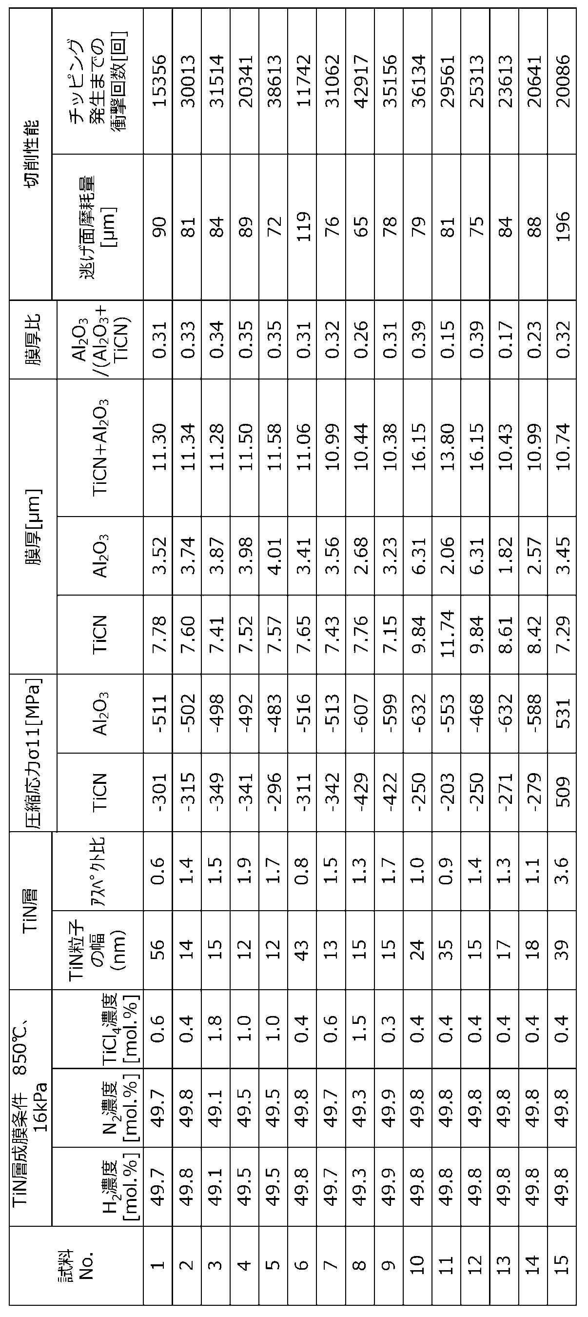
- a TiN layer was formed on the surface of the substrate by the CVD deposition method under the film formation conditions shown in Table 2 under the film formation conditions shown in Table 2. Further, a TiCN layer was formed on the TiN layer. Further, an Al 2 O 3 layer was formed on the TiCN layer.
- Table 1 shows the presence or absence of Co 0.93 W 0.07 in the substrate.
- Table 2 shows the results.
- Sample No. with a Co ratio of 97% by mass or more in the binder phase In Nos. 2 to 5 and 7 to 14, the width of the TiN particles in the TiN layer was 35 nm or less. These samples are sample Nos. With a TiN particle width exceeding 35 nm. Abrasion resistance and fracture resistance superior to those of 1, 6, and 15 were exhibited.
- the width of the TiN particles in the first layer was 20 nm or less, and excellent wear resistance and fracture resistance were exhibited.
Landscapes
- Chemical & Material Sciences (AREA)
- Engineering & Computer Science (AREA)
- Mechanical Engineering (AREA)
- Organic Chemistry (AREA)
- Materials Engineering (AREA)
- Metallurgy (AREA)
- Chemical Kinetics & Catalysis (AREA)
- Inorganic Chemistry (AREA)
- General Chemical & Material Sciences (AREA)
- Ceramic Engineering (AREA)
- Cutting Tools, Boring Holders, And Turrets (AREA)
- Chemical Vapour Deposition (AREA)
- Powder Metallurgy (AREA)
Abstract
Description
以下、本開示のインサートについて、図面を用いて詳細に説明する。但し、以下で参照する各図は、説明の便宜上、実施形態を説明する上で必要な主要部材のみを簡略化して示したものである。したがって、本開示のインサートは、参照する各図に示されていない任意の構成部材を備え得る。また、各図中の部材の寸法は、実際の構成部材の寸法及び各部材の寸法比率などを忠実に表したものではない。これらの点は、後述する切削工具においても同様である。
次に、本開示の切削工具について図面を用いて説明する。

(耐摩耗性試験)
被削材:SAPH440
切削速度:1000m/min
送り:0.15mm/rev
切込み:0.25mm
切削状態:湿式
評価方法:切削長5.0km切削した時点での逃げ面摩耗幅(μm)
(耐チッピング性試験)
被削材:SAPH440 12本溝(10mm幅)付き
切削速度:1000m/min
送り:0.15mm/rev
切込み:0.25mm
切削状態:湿式
評価方法:欠損するまでの衝撃回数(回)
基体として超硬合金を用いた試料No.15のTiN粒子の幅は35nmを超えていた。
3・・・基体
5・・・被覆膜
5a・・第1層
5b・・第2層
5c・・第3層
7・・・切刃
17・・・貫通孔
101・・・切削工具
103・・・ポケット
105・・・ホルダ
107・・・固定ネジ
Claims (10)
- 基体と、該基体の表面を被覆する被覆層とを具備するインサートであって、
前記基体は、
Tiを含む炭窒化物を含有する硬質相と、
Coを含有する結合相と、
を有し、
前記被覆層は、前記基体と接する位置に、複数のTiN粒子を含む第1層を有しており、
前記TiN粒子は、基体の表面に垂直な断面において、前記基体の表面に平行な方向の幅が35nm以下であるインサート。 - 前記TiN粒子は、基体の表面に垂直な断面において、前記基体の表面に平行な方向の幅に対する、前記基体の表面に垂直な方向の高さの比が、1.0~1.7である、請求項1に記載のインサート。
- 前記被覆層は、前記第1層よりも前記基体から遠い位置に、複数のTiCN粒子を含む第2層を有し、該第2層よりも前記基体から遠い位置に、複数のAl2O3粒子を含む第3層を有する、請求項1または2に記載のインサート。
- 前記基体は、前記Co、NiおよびFeを総量で16~25質量%含有する、請求項1~3のいずれかに記載のインサート。
- 前記基体は、Co/(Co+Ni+Fe)で求められるCoの含有率が99.0質量%以上である、請求項1~4のいずれかに記載のインサート。
- 前記基体は、25~1000℃における熱膨張係数が9.0×10⁻⁶/℃以上であり、
前記第2層は、圧縮応力が250~500MPaであり、
前記第3層は、2μm以上の厚みを有し、圧縮応力が450MPa以上であり、前記TiCN層よりも圧縮応力の値が大きい、請求項3~5のいずれかに記載のインサート。 - 前記第3層は、厚みが2.5μm以上、8.0μm以下である、請求項3~6のいずれかに記載のインサート。
- 前記第2層は、厚みが5μm以上、10μm以下である、請求項3~7のいずれかに記載のインサート。
- 前記第3層の厚みは、前記第2層の厚みと前記第3層の厚みの和の0.2~0.4倍の範囲である、請求項3~8のいずれかに記載のインサート。
- 第1端から第2端に向かって延び、前記第1端側にポケットを有するホルダと、
前記ポケットに位置する請求項1~9のいずれかに記載のインサートと、を備えた切削工具。
Priority Applications (4)
| Application Number | Priority Date | Filing Date | Title |
|---|---|---|---|
| JP2020507757A JP7092866B2 (ja) | 2018-03-20 | 2019-03-15 | インサート及びこれを備えた切削工具 |
| CN201980020154.8A CN111886096A (zh) | 2018-03-20 | 2019-03-15 | 刀片和具备它的切削刀具 |
| KR1020207029666A KR102431159B1 (ko) | 2018-03-20 | 2019-03-15 | 인서트 및 이것을 구비한 절삭공구 |
| EP19770446.3A EP3769874A4 (en) | 2018-03-20 | 2019-03-15 | INSERT AND CUTTING TOOL INCLUDING IT |
Applications Claiming Priority (4)
| Application Number | Priority Date | Filing Date | Title |
|---|---|---|---|
| JP2018-052842 | 2018-03-20 | ||
| JP2018052842 | 2018-03-20 | ||
| JP2018-223532 | 2018-11-29 | ||
| JP2018223532 | 2018-11-29 |
Publications (1)
| Publication Number | Publication Date |
|---|---|
| WO2019181790A1 true WO2019181790A1 (ja) | 2019-09-26 |
Family
ID=67986209
Family Applications (1)
| Application Number | Title | Priority Date | Filing Date |
|---|---|---|---|
| PCT/JP2019/010875 Ceased WO2019181790A1 (ja) | 2018-03-20 | 2019-03-15 | インサート及びこれを備えた切削工具 |
Country Status (5)
| Country | Link |
|---|---|
| EP (1) | EP3769874A4 (ja) |
| JP (1) | JP7092866B2 (ja) |
| KR (1) | KR102431159B1 (ja) |
| CN (1) | CN111886096A (ja) |
| WO (1) | WO2019181790A1 (ja) |
Families Citing this family (1)
| Publication number | Priority date | Publication date | Assignee | Title |
|---|---|---|---|---|
| JP7638381B2 (ja) * | 2021-07-30 | 2025-03-03 | 京セラ株式会社 | 被覆工具および切削工具 |
Citations (9)
| Publication number | Priority date | Publication date | Assignee | Title |
|---|---|---|---|---|
| JPH05230587A (ja) * | 1992-02-20 | 1993-09-07 | Mitsubishi Materials Corp | サ−メット |
| JPH11511078A (ja) * | 1995-07-24 | 1999-09-28 | サンドビック アクティエボラーグ | Cvd被覆したチタニウム基炭窒化物切削工具インサート |
| JP2006281361A (ja) * | 2005-03-31 | 2006-10-19 | Kyocera Corp | 表面被覆部材および表面被覆切削工具 |
| WO2008026700A1 (en) * | 2006-08-31 | 2008-03-06 | Kyocera Corporation | Cutting tool, process for producing the same, and method of cutting |
| WO2010010648A1 (ja) * | 2008-07-22 | 2010-01-28 | 日本特殊陶業株式会社 | 切削インサート及び切削工具 |
| JP2011038174A (ja) * | 2009-08-17 | 2011-02-24 | Sumitomo Electric Ind Ltd | 複合焼結体 |
| US20160160347A1 (en) * | 2014-12-08 | 2016-06-09 | Kennametal Inc. | Nanocomposite refractory coatings and applications thereof |
| JP5989930B1 (ja) | 2014-11-27 | 2016-09-07 | 京セラ株式会社 | サーメットおよび切削工具 |
| JP2017035750A (ja) * | 2015-08-10 | 2017-02-16 | 三菱マテリアル株式会社 | 耐塑性変形性、耐異常損傷性および耐摩耗性にすぐれたTi基サーメット切削工具 |
Family Cites Families (10)
| Publication number | Priority date | Publication date | Assignee | Title |
|---|---|---|---|---|
| JPH0615717B2 (ja) * | 1987-07-28 | 1994-03-02 | 東芝タンガロイ株式会社 | 高靱性被覆材料及びその製造方法 |
| US5958569A (en) * | 1995-10-27 | 1999-09-28 | Teledyne Industries, Inc. | Anchored oxide coatings on hard metal cutting tools |
| US6017488A (en) * | 1998-05-11 | 2000-01-25 | Sandvik Ab | Method for nitriding a titanium-based carbonitride alloy |
| SE530755C2 (sv) * | 2006-03-03 | 2008-09-02 | Sandvik Intellectual Property | Belagt cermetskär och användning därav |
| US8080312B2 (en) * | 2006-06-22 | 2011-12-20 | Kennametal Inc. | CVD coating scheme including alumina and/or titanium-containing materials and method of making the same |
| JP5560514B2 (ja) * | 2009-12-25 | 2014-07-30 | 三菱マテリアル株式会社 | 硬質被覆層がすぐれた耐欠損性を発揮する表面被覆切削工具 |
| CN101879612B (zh) * | 2010-06-28 | 2011-12-07 | 株洲钻石切削刀具股份有限公司 | 用于钢材车削的硬质合金涂层刀片 |
| CN108472749B (zh) * | 2015-12-22 | 2020-01-17 | 京瓷株式会社 | 覆盖工具 |
| CN105950937B (zh) * | 2016-05-23 | 2018-01-16 | 株洲钻石切削刀具股份有限公司 | 一种硬质合金刀片及其制备方法 |
| KR102331061B1 (ko) * | 2016-08-22 | 2021-11-25 | 스미토모덴키고교가부시키가이샤 | 경질 재료 및 절삭 공구 |
-
2019
- 2019-03-15 CN CN201980020154.8A patent/CN111886096A/zh active Pending
- 2019-03-15 EP EP19770446.3A patent/EP3769874A4/en active Pending
- 2019-03-15 WO PCT/JP2019/010875 patent/WO2019181790A1/ja not_active Ceased
- 2019-03-15 JP JP2020507757A patent/JP7092866B2/ja active Active
- 2019-03-15 KR KR1020207029666A patent/KR102431159B1/ko active Active
Patent Citations (9)
| Publication number | Priority date | Publication date | Assignee | Title |
|---|---|---|---|---|
| JPH05230587A (ja) * | 1992-02-20 | 1993-09-07 | Mitsubishi Materials Corp | サ−メット |
| JPH11511078A (ja) * | 1995-07-24 | 1999-09-28 | サンドビック アクティエボラーグ | Cvd被覆したチタニウム基炭窒化物切削工具インサート |
| JP2006281361A (ja) * | 2005-03-31 | 2006-10-19 | Kyocera Corp | 表面被覆部材および表面被覆切削工具 |
| WO2008026700A1 (en) * | 2006-08-31 | 2008-03-06 | Kyocera Corporation | Cutting tool, process for producing the same, and method of cutting |
| WO2010010648A1 (ja) * | 2008-07-22 | 2010-01-28 | 日本特殊陶業株式会社 | 切削インサート及び切削工具 |
| JP2011038174A (ja) * | 2009-08-17 | 2011-02-24 | Sumitomo Electric Ind Ltd | 複合焼結体 |
| JP5989930B1 (ja) | 2014-11-27 | 2016-09-07 | 京セラ株式会社 | サーメットおよび切削工具 |
| US20160160347A1 (en) * | 2014-12-08 | 2016-06-09 | Kennametal Inc. | Nanocomposite refractory coatings and applications thereof |
| JP2017035750A (ja) * | 2015-08-10 | 2017-02-16 | 三菱マテリアル株式会社 | 耐塑性変形性、耐異常損傷性および耐摩耗性にすぐれたTi基サーメット切削工具 |
Non-Patent Citations (1)
| Title |
|---|
| See also references of EP3769874A4 |
Also Published As
| Publication number | Publication date |
|---|---|
| EP3769874A1 (en) | 2021-01-27 |
| JP7092866B2 (ja) | 2022-06-28 |
| EP3769874A4 (en) | 2021-12-01 |
| KR20200128150A (ko) | 2020-11-11 |
| JPWO2019181790A1 (ja) | 2021-04-15 |
| KR102431159B1 (ko) | 2022-08-10 |
| CN111886096A (zh) | 2020-11-03 |
Similar Documents
| Publication | Publication Date | Title |
|---|---|---|
| JP7105299B2 (ja) | 被覆工具及びこれを備えた切削工具 | |
| US10744568B2 (en) | Coated tool | |
| JP4854359B2 (ja) | 表面被覆切削工具 | |
| KR102731820B1 (ko) | 피복 공구 | |
| JP7092866B2 (ja) | インサート及びこれを備えた切削工具 | |
| JP7057419B2 (ja) | インサート及びこれを備えた切削工具 | |
| JP7057420B2 (ja) | インサート及びこれを備えた切削工具 | |
| KR102780216B1 (ko) | 피복 공구 및 그것을 구비한 절삭 공구 | |
| JP7092867B2 (ja) | 工具及びこれを備えた切削工具 | |
| JP7057418B2 (ja) | インサート及びこれを備えた切削工具 | |
| CN118900926A (zh) | 硬质合金及使用其的涂层刀具、切削刀具 | |
| WO2024181016A1 (ja) | 超硬合金、被覆工具及び切削工具 | |
| WO2024095655A1 (ja) | 被覆工具および切削工具 | |
| WO2020111122A1 (ja) | 被覆工具およびそれを備えた切削工具 |
Legal Events
| Date | Code | Title | Description |
|---|---|---|---|
| 121 | Ep: the epo has been informed by wipo that ep was designated in this application |
Ref document number: 19770446 Country of ref document: EP Kind code of ref document: A1 |
|
| ENP | Entry into the national phase |
Ref document number: 2020507757 Country of ref document: JP Kind code of ref document: A |
|
| NENP | Non-entry into the national phase |
Ref country code: DE |
|
| ENP | Entry into the national phase |
Ref document number: 20207029666 Country of ref document: KR Kind code of ref document: A |
|
| ENP | Entry into the national phase |
Ref document number: 2019770446 Country of ref document: EP Effective date: 20201020 |