WO2019181791A1 - 工具及びこれを備えた切削工具 - Google Patents
工具及びこれを備えた切削工具 Download PDFInfo
- Publication number
- WO2019181791A1 WO2019181791A1 PCT/JP2019/010876 JP2019010876W WO2019181791A1 WO 2019181791 A1 WO2019181791 A1 WO 2019181791A1 JP 2019010876 W JP2019010876 W JP 2019010876W WO 2019181791 A1 WO2019181791 A1 WO 2019181791A1
- Authority
- WO
- WIPO (PCT)
- Prior art keywords
- layer
- substrate
- insert
- insert according
- thickness
- Prior art date
- Legal status (The legal status is an assumption and is not a legal conclusion. Google has not performed a legal analysis and makes no representation as to the accuracy of the status listed.)
- Ceased
Links
Images

Classifications
-
- C—CHEMISTRY; METALLURGY
- C23—COATING METALLIC MATERIAL; COATING MATERIAL WITH METALLIC MATERIAL; CHEMICAL SURFACE TREATMENT; DIFFUSION TREATMENT OF METALLIC MATERIAL; COATING BY VACUUM EVAPORATION, BY SPUTTERING, BY ION IMPLANTATION OR BY CHEMICAL VAPOUR DEPOSITION, IN GENERAL; INHIBITING CORROSION OF METALLIC MATERIAL OR INCRUSTATION IN GENERAL
- C23C—COATING METALLIC MATERIAL; COATING MATERIAL WITH METALLIC MATERIAL; SURFACE TREATMENT OF METALLIC MATERIAL BY DIFFUSION INTO THE SURFACE, BY CHEMICAL CONVERSION OR SUBSTITUTION; COATING BY VACUUM EVAPORATION, BY SPUTTERING, BY ION IMPLANTATION OR BY CHEMICAL VAPOUR DEPOSITION, IN GENERAL
- C23C16/00—Chemical coating by decomposition of gaseous compounds, without leaving reaction products of surface material in the coating, i.e. chemical vapour deposition [CVD] processes
- C23C16/22—Chemical coating by decomposition of gaseous compounds, without leaving reaction products of surface material in the coating, i.e. chemical vapour deposition [CVD] processes characterised by the deposition of inorganic material, other than metallic material
- C23C16/30—Deposition of compounds, mixtures or solid solutions, e.g. borides, carbides, nitrides
- C23C16/40—Oxides
- C23C16/403—Oxides of aluminium, magnesium or beryllium
-
- C—CHEMISTRY; METALLURGY
- C22—METALLURGY; FERROUS OR NON-FERROUS ALLOYS; TREATMENT OF ALLOYS OR NON-FERROUS METALS
- C22C—ALLOYS
- C22C29/00—Alloys based on carbides, oxides, nitrides, borides, or silicides, e.g. cermets, or other metal compounds, e.g. oxynitrides, sulfides
- C22C29/005—Alloys based on carbides, oxides, nitrides, borides, or silicides, e.g. cermets, or other metal compounds, e.g. oxynitrides, sulfides comprising a particular metallic binder
-
- C—CHEMISTRY; METALLURGY
- C22—METALLURGY; FERROUS OR NON-FERROUS ALLOYS; TREATMENT OF ALLOYS OR NON-FERROUS METALS
- C22C—ALLOYS
- C22C29/00—Alloys based on carbides, oxides, nitrides, borides, or silicides, e.g. cermets, or other metal compounds, e.g. oxynitrides, sulfides
- C22C29/02—Alloys based on carbides, oxides, nitrides, borides, or silicides, e.g. cermets, or other metal compounds, e.g. oxynitrides, sulfides based on carbides or carbonitrides
- C22C29/04—Alloys based on carbides, oxides, nitrides, borides, or silicides, e.g. cermets, or other metal compounds, e.g. oxynitrides, sulfides based on carbides or carbonitrides based on carbonitrides
-
- C—CHEMISTRY; METALLURGY
- C23—COATING METALLIC MATERIAL; COATING MATERIAL WITH METALLIC MATERIAL; CHEMICAL SURFACE TREATMENT; DIFFUSION TREATMENT OF METALLIC MATERIAL; COATING BY VACUUM EVAPORATION, BY SPUTTERING, BY ION IMPLANTATION OR BY CHEMICAL VAPOUR DEPOSITION, IN GENERAL; INHIBITING CORROSION OF METALLIC MATERIAL OR INCRUSTATION IN GENERAL
- C23C—COATING METALLIC MATERIAL; COATING MATERIAL WITH METALLIC MATERIAL; SURFACE TREATMENT OF METALLIC MATERIAL BY DIFFUSION INTO THE SURFACE, BY CHEMICAL CONVERSION OR SUBSTITUTION; COATING BY VACUUM EVAPORATION, BY SPUTTERING, BY ION IMPLANTATION OR BY CHEMICAL VAPOUR DEPOSITION, IN GENERAL
- C23C16/00—Chemical coating by decomposition of gaseous compounds, without leaving reaction products of surface material in the coating, i.e. chemical vapour deposition [CVD] processes
- C23C16/22—Chemical coating by decomposition of gaseous compounds, without leaving reaction products of surface material in the coating, i.e. chemical vapour deposition [CVD] processes characterised by the deposition of inorganic material, other than metallic material
- C23C16/30—Deposition of compounds, mixtures or solid solutions, e.g. borides, carbides, nitrides
- C23C16/36—Carbonitrides
-
- B—PERFORMING OPERATIONS; TRANSPORTING
- B22—CASTING; POWDER METALLURGY
- B22F—WORKING METALLIC POWDER; MANUFACTURE OF ARTICLES FROM METALLIC POWDER; MAKING METALLIC POWDER; APPARATUS OR DEVICES SPECIALLY ADAPTED FOR METALLIC POWDER
- B22F3/00—Manufacture of workpieces or articles from metallic powder characterised by the manner of compacting or sintering; Apparatus specially adapted therefor ; Presses and furnaces
- B22F3/24—After-treatment of workpieces or articles
- B22F2003/241—Chemical after-treatment on the surface
- B22F2003/242—Coating
-
- B—PERFORMING OPERATIONS; TRANSPORTING
- B22—CASTING; POWDER METALLURGY
- B22F—WORKING METALLIC POWDER; MANUFACTURE OF ARTICLES FROM METALLIC POWDER; MAKING METALLIC POWDER; APPARATUS OR DEVICES SPECIALLY ADAPTED FOR METALLIC POWDER
- B22F5/00—Manufacture of workpieces or articles from metallic powder characterised by the special shape of the product
- B22F2005/001—Cutting tools, earth boring or grinding tool other than table ware
-
- B—PERFORMING OPERATIONS; TRANSPORTING
- B22—CASTING; POWDER METALLURGY
- B22F—WORKING METALLIC POWDER; MANUFACTURE OF ARTICLES FROM METALLIC POWDER; MAKING METALLIC POWDER; APPARATUS OR DEVICES SPECIALLY ADAPTED FOR METALLIC POWDER
- B22F2998/00—Supplementary information concerning processes or compositions relating to powder metallurgy
- B22F2998/10—Processes characterised by the sequence of their steps
Definitions
- the present disclosure relates to a tool used in cutting and a cutting tool including the tool.
- cermets mainly composed of titanium (Ti) are widely used as the base material for members that require wear resistance, slidability, and fracture resistance, such as cutting tools, wear-resistant members, and sliding members. Yes.
- Patent Document 1 by controlling the firing conditions, the first bonded phase in which the mass ratio (W / (Co + Ni)) of tungsten contained in the metal phase in the cermet is 0.8 or less, and (W / ( It is described that a second bonded phase having Co + Ni)) of 1.2 or more is present in the cermet.
- the object of the present invention is to increase the wear resistance and fracture resistance of cermets at high temperatures.
- the insert according to the present disclosure includes a substrate made of a cermet containing a hard phase containing a carbonitride containing Ti and a binder phase containing Co.
- the substrate contains Co 0.93 W 0.07 .
- the cutting tool of the present disclosure includes a holder that extends from a first end toward the second end and has a pocket on the first end side, and the above-described insert that is located in the pocket located in the pocket.
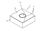
- FIG. 1 is a perspective view illustrating an example of the insert of the present disclosure.
- FIG. 2 is an enlarged schematic view of a cross section near the surface of the insert of the present disclosure.
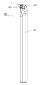
- FIG. 3 is a plan view illustrating an example of the cutting tool of the present disclosure.
- the insert 1 of the present disclosure has a base 3 as shown in FIGS.
- the insert 1 of the present disclosure may include a coating layer 5 that covers at least a part of the substrate 3.
- the shape of the insert 1 of the present disclosure is, for example, a square plate shape, and the upper surface in FIG. 1 is a so-called rake surface. Moreover, it has a lower surface opposite to the upper surface, and has side surfaces connected to each between the upper surface and the lower surface. At least a part of the side surface is a so-called flank.
- the insert 1 of the present disclosure has a cutting edge 7 positioned at at least a part of a ridge line where the upper surface and the side surface intersect. In other words, it has the cutting edge 7 located in at least one part of the ridgeline where a rake face and a flank face cross.
- the entire outer periphery of the rake face may be the cutting edge 7, but the insert 1 is not limited to such a configuration, for example, only one side of the square rake face, or You may have the cutting edge 7 partially.
- the size of the insert 1 is not particularly limited.
- the length of one side of the rake face is set to about 3 to 20 mm.
- the thickness of the insert 1 is set to about 1 to 20 mm, for example.
- the base 3 of the insert 1 of the present disclosure is composed of a cermet containing a hard phase containing carbonitride containing Ti and a binder phase containing Co.
- the cermet is a so-called TiCN-based cermet.
- the cermet includes one containing TiC or TiN in addition to TiCN.
- the substrate 3 in the insert 1 of the present disclosure contains Co 0.93 W 0.07 . Thereby, it becomes the insert 1 excellent in abrasion resistance and fracture resistance.
- Co 0.93 W 0.07 is a crystal represented by PDF: 01-071-7509 of the JCPDS card.
- the ratio of Co 0.93 W 0.07 to the total crystal in the crystal phase analysis by X-ray diffraction may be 5 to 10. Also, it may be 8-10. With such high content of Co 0.93 W 0.07, the wear resistance of the base body 3, a high fracture resistance.
- the ratio of the above Co 0.93 W 0.07 is the ratio of all detected crystals by the X-ray apparatus: X'Pert Pro 2 ⁇ : 10-100, manufactured by PANalytical, and the lead belt method using analysis software Rietan-FP. The ratio of 0.93 W 0.07 is calculated.
- the substrate 3 may contain 16 to 25% by mass of Co, Ni and Fe in total.
- the substrate 3 may have a Co content of 99.0% by mass or more obtained by Co / (Co + Ni + Fe).
- the Co content can also be expressed as the Co content of the binder phase.
- the Co content may be 99.5% by mass or more.
- the Co content (% by mass) is a value obtained by measuring the mass of Co, Fe, and Ni contained in the insert and dividing the mass of Co by the total amount and multiplying by 100. In other words, the total amount of Fe and Ni in the binder phase included in the insert 1 of the present disclosure may be less than 1% by mass.
- the metal functioning as the binder phase is almost only Co
- Co 0.93 W 0.07 is moderately dispersed in the base 3 and the base 3 having high wear resistance and chipping resistance can be easily obtained.
- the binder phase is only Co
- the average particle size of the hard phase raw material powder may be 1 ⁇ m or less, and further 0.6 ⁇ m or less.
- the Co content in the substrate 3 may be 16% by mass or more.
- the binder phase may occupy a ratio of 5 to 25 area% in the cross section of the substrate 3.
- the binder phase may consist of only Co and W except for inevitable impurities.
- content of each element may be 0.5 mass% or less.
- the insert 1 of the present disclosure may have a coating layer 5 on the substrate 3 as shown in FIG.
- the wear resistance of the insert 1 is high.
- the covering layer 5 may be formed by a CVD method or a PVD method.
- the covering layer 5 may have, for example, a first layer 5 a containing TiN particles on the side close to the base 3.
- the covering layer 5 has a second layer 5b containing TiCN particles at a position farther from the substrate 3 than the first layer 5a, and a third layer containing Al 2 O 3 particles at a position farther from the substrate 3 than the second layer 5b.
- the layer 5c may be included.
- the width of the TiN particles in the direction parallel to the surface of the base 3 in the cross section perpendicular to the surface of the base 3 (hereinafter also referred to as the width of the TiN particles). May be 5 to 20 nm. With such a configuration, the adhesion between the first layer 5a and the substrate 3 is excellent. Moreover, since the width
- the width of the TiN particles may be measured at a position of 0.05 ⁇ m from the surface of the substrate 3.
- the width of the TiN particles may be measured at a position that is half the thickness of the first layer 5a.
- the ratio of the height of the TiN particles in the direction perpendicular to the surface of the substrate 3 to the width of the TiN particles in the direction parallel to the surface of the substrate 3 (hereinafter also referred to as the aspect ratio) is 1.0 to 1. 7 may be sufficient. With such a configuration, the adhesion between the first layer 5a and the substrate 3 is excellent.
- the aspect ratio of TiN particles may be measured with TiN particles present at a position of 0.05 ⁇ m from the surface of the substrate 3.
- the thickness of the first layer 5a may be 0.1 to 1.0 ⁇ m.
- the thickness of the first layer 5a is 0.1 ⁇ m or more, the binder phase component contained in the substrate 3 is prevented from diffusing into the film, and the chipping resistance is excellent.
- the thickness of the first layer 5a is 1.0 ⁇ m or less, the TiCN particles contained in the upper second layer 5b become fine and have excellent wear resistance.
- the thickness of the first layer 5a may be 0.3 to 0.7 ⁇ m.
- the insert 1 has a first layer 5 a on the base 3. Further, the second layer 5b is provided on the first layer 5a.
- the second layer 5b contains TiCN particles.
- the thermal expansion coefficient of the TiCN particles is about 8 ⁇ 10 ⁇ 6 / ° C., and if the thermal expansion coefficient of the substrate 3 is 9.0 ⁇ 10 ⁇ 6 / ° C. or more, the thermal expansion coefficient of the second layer 5 b is Is smaller than the coefficient of thermal expansion.
- the second layer 5b is located between the base 3 and the first layer 5c, and prevents the first layer 5c from peeling off and suppresses abrasive wear.
- the third layer 5c contains Al 2 O 3 particles.
- the thermal expansion coefficient of the Al 2 O 3 particles is about 7.2 ⁇ 10 ⁇ 6 / ° C., which is smaller than the thermal expansion coefficients of the base 3 and the second layer 5b.
- the base body 3 and the second layer 5b may be in direct contact with each other, and the first layer 5a may be positioned between them, for example, as in the example of FIG.
- the first layer 5a does not need to be composed of pure TiN particles alone, and may contain, for example, O or C.
- the second layer 5b and the third layer 5c may be in direct contact with each other, and for example, a TiN layer (not shown) may be located between them.
- an appropriate compressive stress can be applied to the second layer 5b and the third layer 5c by adjusting the thermal expansion coefficient of the base 3 and the thickness of the third layer 5c.
- the thickness of the third layer 5c is 2 ⁇ m or more.
- the compressive stress applied to the second layer 5b is 250 to 500 MPa
- the compressive stress applied to the third layer 5c is set to 450 MPa or more
- the value of the compressive stress applied to the third layer 5c is higher than the compressive stress applied to the second layer 5b. You may enlarge it. With such a configuration, the insert 1 is excellent in wear resistance and durability.
- the residual stress when the residual stress is a negative value, the residual stress is a compressive stress.
- the value of the compressive stress is indicated, it is expressed as an absolute value without adding a minus.
- the third layer 5c When comparing the second layer 5b and the third layer 5c constituting the coating layer 5, the third layer 5c is located farther from the substrate 3. Therefore, when processing a workpiece using the cutting tool 1 of the present disclosure, the third layer 5c comes into contact with the workpiece before the second layer 5b.
- the third layer 5c contains Al 2 O 3 particles and has a thickness of 2 ⁇ m or more, the wear resistance and oxidation resistance are high.
- the thickness of the third layer 5c may be 2.5 ⁇ m or more and 8.0 ⁇ m or less.
- the insert 1 having such a configuration is further excellent in wear resistance and oxidation resistance.
- the sum of the thickness of the second layer 5b and the thickness of the third layer 5c may be 7 ⁇ m or more and 18 ⁇ m or less. Moreover, it is good also as 8 micrometers or more and 16 micrometers or less.
- the second layer 5b may have a thickness of 5 ⁇ m or more and 10 ⁇ m or less. In such a range, the insert 1 is excellent in wear resistance and fracture resistance.
- the thickness of the third layer 5c may be 0.2 to 0.4 times the sum of the thickness of the second layer 5b and the thickness of the third layer 5c.
- the insert 1 having such a configuration is excellent in wear resistance and chipping resistance.
- the third layer 5 c may have the C axis of the Al 2 O 3 crystal oriented along a direction perpendicular to the main surface of the substrate 3.
- ⁇ -Al 2 O 3 particles may be contained, and the ⁇ -Al 2 O 3 particles may have a columnar shape extending in a direction perpendicular to the main surface of the substrate 3.
- the base 3 in the insert 1 of the present disclosure may have a binder phase-enriched layer having a higher binder phase ratio than the inside of the base 3 on the surface.
- the thickness of the binder phase enriched layer may be 1 ⁇ m or more and 10 ⁇ m or less.
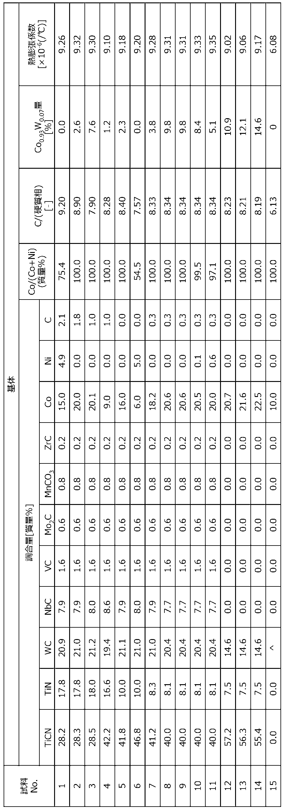
- Table 1 shows the ratio of the raw material powder used as the base of the insert used in Examples described later.
- the average particle diameter of each raw material was 1 ⁇ m or less.
- Co 0.93 W 0.07 contained in the insert of the present disclosure is formed by reaction of Co and W used as raw materials in the manufacturing process of the insert.
- a substrate containing Co 0.93 W 0.07 can be obtained by adjusting the amount of C contained during preparation of the raw material.
- C / (hard phase) is 9.1 or less, a substrate containing Co 0.93 W 0.07 can be obtained.
- C / (hard phase) is 8.0 or more, an increase in the ⁇ phase can be suppressed, so that a relative decrease in Co 0.93 W 0.07 can be suppressed.
- the amount of C in the raw material includes, for example, C contained in each raw material powder in addition to C added as carbon.
- a hard phase refers to what can exist as a hard phase in an insert, for example, the metal, oxide, and carbonate of Fe, Ni, Co, Mn, Mo are not contained.
- a dense substrate can be obtained by baking in the temperature range.
- each is held at 200 ° C. and 300 ° C. for 1 hour in a vacuum, and then heated to 450 ° C. and held for 1 hour.
- CO 2 gas is introduced into the degreasing furnace so as to have a pressure of 1 to 5 kPa in order to suppress a decrease in C added as a raw material in the process at 450 ° C. By doing in this way, C amount can be controlled precisely.
- the substrate preferably has a thermal expansion coefficient of 9.0 ⁇ 10 ⁇ 6 or more at 25 to 1000 ° C.
- a coating layer as needed.
- a first layer containing TiN particles is formed on the surface of the substrate.
- a second layer containing TiCN particles is formed on the first layer.
- a third layer containing Al 2 O 3 particles is formed on the second layer.
- the first layer, the second layer, and the third layer may be formed by a chemical vapor deposition (CVD) method.
- CVD chemical vapor deposition
- Co The ratio is preferably 99.9% by mass or more.
- the first layer has a temperature of 800 to 900 ° C., a pressure of 8 to 20 kPa, a TiCl 4 concentration of 0.2 to 2.5 mol%, an N 2 concentration of 25.0 to 49.9 mol%, and an H 2 concentration of 40. You may form into a film on the conditions of 0-74.8 mol%.
- the compressive stress applied to the second layer and the third layer can also be controlled by controlling the thicknesses of the second layer and the third layer.
- the cutting tool 101 of the present disclosure is, for example, a rod-shaped body that extends from a first end (upper end in FIG. 3) to a second end (lower end in FIG. 3), as shown in FIG.
- the cutting tool 101 includes a holder 105 having a pocket 103 on the first end side (front end side) and the insert 1 positioned in the pocket 103. Since the cutting tool 101 includes the insert 1, it can perform stable cutting over a long period of time.
- the pocket 103 is a portion to which the insert 1 is mounted, and has a seating surface parallel to the lower surface of the holder 105 and a restraining side surface inclined with respect to the seating surface. Further, the pocket 103 is opened on the first end side of the holder 105.
- the insert 1 is located in the pocket 103. At this time, the lower surface of the insert 1 may be in direct contact with the pocket 103, and a sheet (not shown) may be sandwiched between the insert 1 and the pocket 103.
- the insert 1 is mounted on the holder 105 so that at least a part of the portion used as the cutting edge 7 on the ridge line where the rake face and the flank face intersect protrudes outward from the holder 105.
- the insert 1 is attached to the holder 105 with a fixing screw 107. That is, by inserting the fixing screw 107 into the through hole 17 of the insert 1 and inserting the tip of the fixing screw 107 into a screw hole (not shown) formed in the pocket 103 and screwing the screw portions together, 1 is attached to the holder 105.
- steel cast iron or the like
- steel having high toughness may be used.
- a cutting tool used for so-called turning is illustrated.
- the turning process include an inner diameter process, an outer diameter process, a grooving process, and an end face process.
- the cutting tool is not limited to that used for turning. For example, you may use the insert 1 of said embodiment for the cutting tool used for a turning process.
- the substrate was produced as follows. A tool-shaped compact was prepared using the raw material powder in the ratio shown in Table 1, the binder component was removed, and then fired to prepare a substrate. Of these samples, Sample No. The substrates 1 to 14 are so-called cermets. Sample No. The substrate 15 is a so-called cemented carbide. In the degreasing step, each was held at 200 ° C. and 300 ° C. for 1 hour in a vacuum, then heated to 450 ° C. and held for 1 hour. At this time, CO 2 gas was introduced into the degreasing furnace at a pressure of 3 kPa at a process of 450 ° C.
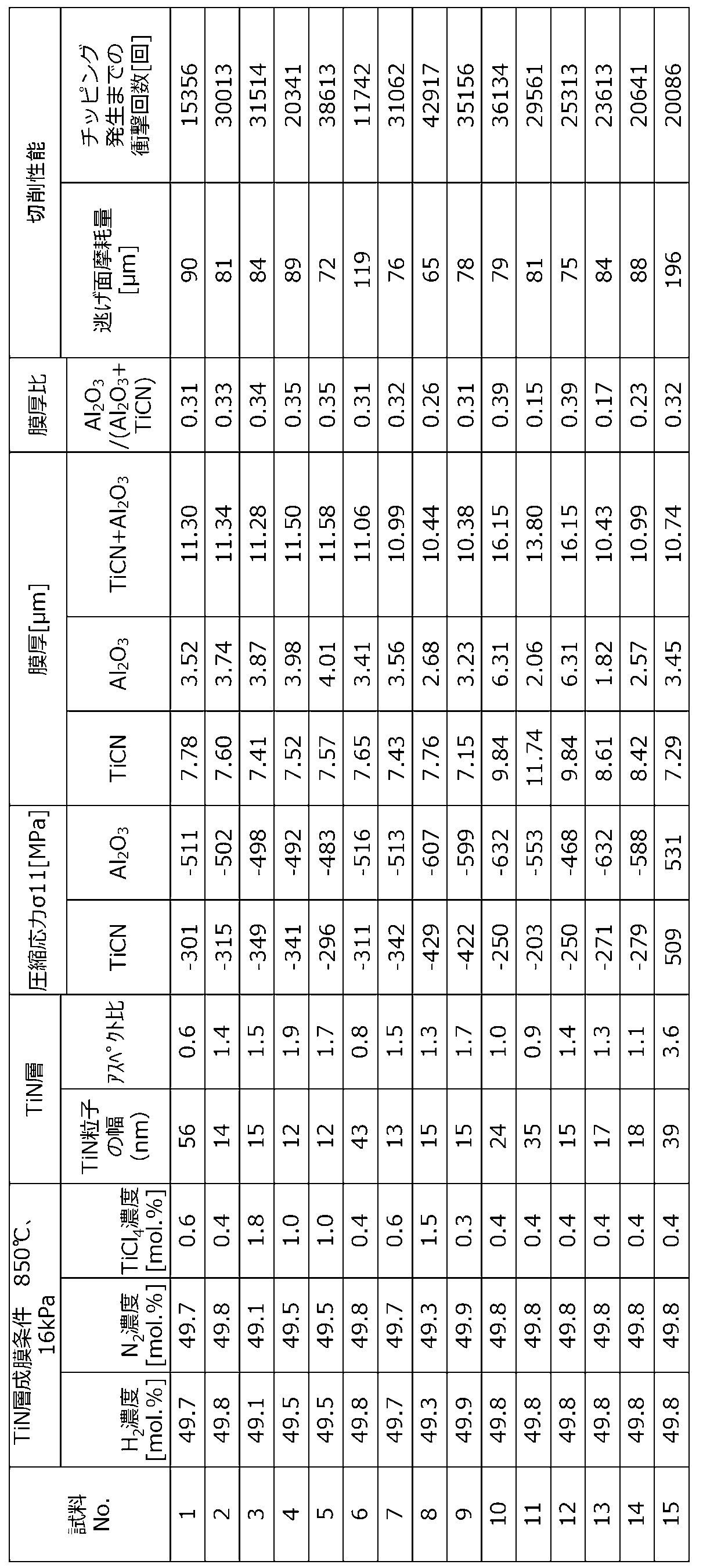
- the first layer was formed on the surface of the substrate by the CVD deposition method under the film formation conditions shown in Table 2 under the film formation conditions shown in Table 2. Further, a second layer was formed on the first layer. Furthermore, a third layer was formed on the second layer.
- Table 1 shows the presence or absence of Co 0.93 W 0.07 in the substrate.
- Table 2 shows the results.
- the substrate had a binder phase enriched layer.
- the obtained insert was subjected to a cutting test under the following conditions.
- (Abrasion resistance test) Work material: SAPH440 Cutting speed: 1000 m / min Feed: 0.15mm / rev Cutting depth: 0.25mm Cutting condition: Wet evaluation method: Cutting length 5.0 km flank wear width ( ⁇ m) at the time of cutting (Chipping resistance test)
- Table 1 Further, the width of the TiN particles in the first layer in the direction parallel to the surface of the substrate was measured. The results are shown in Table 2. Table 2 also shows the aspect ratio of TiN particles.
- Sample No. 1 which is an insert comprising a substrate containing Co 0.93 W 0.07 .
- Samples Nos. 2 to 5 and 7 to 14 are samples No. having no Co 0.93 W 0.07 Abrasion resistance and fracture resistance superior to those of 1, 6, and 15 were exhibited.
- the crystal phase analysis by X-ray diffraction of the substrate to the total crystal the proportion of Co 0.93 W 0.07 is in the range of 5 to 12 Sample No. Nos. 3 and 8 to 13 showed particularly excellent wear resistance and fracture resistance.
- the sample having a width of TiN particles of the first layer of 20 nm or less was excellent in adhesion between the substrate and the first layer.
- a sample having an aspect ratio of 1.0 to 1.7 or less was excellent in adhesion between the substrate and the first layer.
Landscapes
- Chemical & Material Sciences (AREA)
- Engineering & Computer Science (AREA)
- Materials Engineering (AREA)
- Mechanical Engineering (AREA)
- Metallurgy (AREA)
- Organic Chemistry (AREA)
- Inorganic Chemistry (AREA)
- General Chemical & Material Sciences (AREA)
- Chemical Kinetics & Catalysis (AREA)
- Cutting Tools, Boring Holders, And Turrets (AREA)
- Chemical Vapour Deposition (AREA)
Abstract
本開示のインサートは、Tiを含む炭窒化物を含有する硬質相と、Coを含有する結合相とを含有するサーメットからなる基体を具備する。前記基体は、Co0.93W0.07を含有する。また、本開示の切削工具は、第1端から第2端に向かって延び、前記第1端側にポケットを有するホルダと、前記ポケットに位置するポケットに位置する上述のインサートとを備える。
Description
本開示は、切削加工において用いられる工具及びこれを備えた切削工具に関する。
現在、切削工具や耐摩耗性部材、摺動部材等の耐摩耗性や摺動性、耐欠損性を必要とする部材の基体として、チタン(Ti)を主成分とするサーメットが広く使われている。
例えば、特許文献1では、焼成条件を制御することで、サーメット中の金属相に含まれるタングステンの質量比(W/(Co+Ni))が0.8以下の第1結合相と、(W/(Co+Ni))が1.2以上の第2結合相とをサーメット中に存在させることが記載されている。
この発明は、サーメットの高温における耐摩耗性及び耐欠損性を高くすることを目的としている。
本開示のインサートは、Tiを含む炭窒化物を含有する硬質相と、Coを含有する結合相とを含有するサーメットからなる基体を具備する。前記基体は、Co0.93W0.07を含有する。また、本開示の切削工具は、第1端から第2端に向かって延び、前記第1端側にポケットを有するホルダと、前記ポケットに位置するポケットに位置する上述のインサートとを備える。
<インサート>
以下、本開示のインサートについて、図面を用いて詳細に説明する。但し、以下で参照する各図は、説明の便宜上、実施形態を説明する上で必要な主要部材のみを簡略化して示したものである。したがって、本開示のインサートは、参照する各図に示されていない任意の構成部材を備え得る。また、各図中の部材の寸法は、実際の構成部材の寸法及び各部材の寸法比率などを忠実に表したものではない。これらの点は、後述する切削工具においても同様である。
以下、本開示のインサートについて、図面を用いて詳細に説明する。但し、以下で参照する各図は、説明の便宜上、実施形態を説明する上で必要な主要部材のみを簡略化して示したものである。したがって、本開示のインサートは、参照する各図に示されていない任意の構成部材を備え得る。また、各図中の部材の寸法は、実際の構成部材の寸法及び各部材の寸法比率などを忠実に表したものではない。これらの点は、後述する切削工具においても同様である。
本開示のインサート1は、図1、2に示すように基体3を有する。本開示のインサート1は基体3の少なくとも一部を覆う被覆層5を具備していてもよい。
本開示のインサート1の形状は、例えば、四角板形状であって、図1における上面は、いわゆるすくい面である。また、上面の反対に下面を有し、上面と下面との間にそれぞれに繋がる側面を有する。側面において少なくても一部は、いわゆる逃げ面である。
本開示のインサート1は、上面と側面とが交わる稜線の少なくとも一部に位置する切刃7を有している。言い換えれば、すくい面と逃げ面とが交わる稜線の少なくとも一部に位置する切刃7を有している。
インサート1においては、すくい面の外周の全体が切刃7となっていてもよいが、インサート1はこのような構成に限定されるものではなく、例えば、四角形のすくい面における一辺のみ、若しくは、部分的に切刃7を有するものであってもよい。
インサート1の大きさは特に限定されるものではないが、例えば、すくい面の一辺の長さが3~20mm程度に設定される。また、インサート1の厚みは、例えば1~20mm程度に設定される。
本開示のインサート1の基体3は、Tiを含む炭窒化物を含有する硬質相とCoを含有する結合相とを含有するサーメットからなる。サーメットは、いわゆるTiCN基サーメットである。具体的には、サーメットとして、TiCNに加え、TiC又はTiN等を含有するものが挙げられる。
本開示のインサート1における基体3は、Co0.93W0.07を含有している。これにより、耐摩耗性、耐欠損性に優れたインサート1となる。なお、Co0.93W0.07は、JCPDSカードのPDF:01-071-7509で示される結晶である。
インサート1中に含まれるCo0.93W0.07の量が、例えば、X線回折によって、Co0.93W0.07が特定できないほど少ないと効果を奏しない。
本開示のインサート1は、X線回折による結晶相解析において、総結晶に占める、前記Co0.93W0.07の割合が、5~10であってもよい。また、8~10であってもよい。このようにCo0.93W0.07の含有量が多いと、基体3の耐摩耗性、耐欠損性が高い。
上記のCo0.93W0.07の割合は、X線装置:PANalytical社製 X’Pert Pro 2θ:10~100、解析ソフトRIETAN-FPを用いたリードベルト法により、検出された全ての結晶の割合にしめるCo0.93W0.07の割合を計算したものである。
また、基体3は、Co、NiおよびFeを総量で16~25質量%含有していてもよい。
また、基体3は、Co/(Co+Ni+Fe)で求められるCoの含有率が99.0質量%以上であってもよい。このCoの含有率は、言い換えると、結合相のCoの含有率とも表現できる。また、さらにCoの含有率は、99.5質量%以上としてもよい。このCoの含有率(質量%)は、インサートに含まれるCo、Fe、Niの質量を測定し、その総量でCoの質量を割って100倍した値である。本開示のインサート1に含まれる結合相中のFeおよびNiの総量は1質量%未満としてもよいとも言い換えることができる。このように結合相として機能する金属をほぼCoのみとすると、Co0.93W0.07が基体3に適度に分散し、耐摩耗性、耐欠損性が高い基体3が得られやすい。結合相がCoのみである場合、例えば、硬質相の原料粉末として平均粒径は、1μm以下、さらには、0.6μm以下であってもよい。なお、基体3に占めるCoの含有量は、16質量%以上であってもよい。
また、結合相としてFeおよびNiを含むときには、硬質相と結合相の濡れ性が向上する。
結合相は、基体3の断面において、5~25面積%の割合を占めていてもよい。結合相は、不可避不純物を除き、CoとWのみからなっていてもよい。結合相が、CoとW以外の元素を含有する場合、それぞれの元素の含有量は0.5質量%以下であってもよい。
また、本開示のインサート1は、図2に示すように基体3の上に被覆層5を有していてもよい。インサート1が被覆層5を有すると、インサート1の耐摩耗性が高い。
また、被覆層5は、CVD法やPVD法によって形成されるものであってもよい。被覆層5は、基体3に近い側に、例えば、TiN粒子を含有する第1層5aを有していてもよい。被覆層5は、第1層5aよりも基体3から遠い位置にTiCN粒子を含む第2層5bを有し、第2層5bよりも基体3から遠い位置にAl2O3粒子を含む第3層5cを有していてもよい。
第1層5aが、複数のTiN粒子を有している場合、基体3の表面に垂直な断面において、TiN粒子の基体3の表面に平行な方向の幅(以下、TiN粒子の幅ともいう)が5~20nmとしてもよい。このような構成を有すると第1層5aと基体3との密着性が優れる。また、被覆膜5の粒子の幅が小さいため被覆膜5の耐摩耗性が高い。
なお、TiN粒子の幅の測定は、基体3の表面から、0.05μmの位置で測定するとよい。また、第1層5aの厚みが、0.05μm以下の場合には、第1層5aの厚みの半分の位置でTiN粒子の幅を測定するとよい。
また、基体3の表面に平行な方向のTiN粒子の幅に対する、前記基体3の表面に垂直な方向のTiN粒子の高さの比(以下、アスペクト比ともいう)が、1.0~1.7であってもよい。このような構成を有すると、第1層5aと基体3との密着力が優れる。
なお、TiN粒子のアスペクト比は、基体3の表面から、0.05μmまでの位置に存在するTiN粒子で測定するとよい。
また、第1層5aの厚みは、0.1~1.0μmであってもよい。第1層5aの厚みが、0.1μm以上であると、基体3に含まれる結合相成分が被膜へ拡散することを抑制し、耐欠損性に優れる。第1層5aの厚みが、1.0μm以下であると、上層の第2層5bに含まれるTiCN粒子が微細になり耐摩耗性に優れる。特に、第1層5aの厚みは、0.3~0.7μmとしてもよい。
図2に示す例では、インサート1は、基体3の上に第1層5aを有している。また、第1層5aの上に第2層5bを有している。第2層5bにはTiCN粒子が含まれている。TiCN粒子の熱膨張係数は、8×10⁻⁶/℃程度であり、基体3の熱膨張係数を9.0×10-6/℃以上とすると、第2層5bの熱膨張係数は基体3の熱膨張係数よりも小さい。第2層5bは、基体3と第1層5cとの間にあって、第1層5cが剥がれてしまうことを抑制するとともに、アブレシブ摩耗を抑制する。
第3層5cにはAl2O3粒子が含まれている。Al2O3粒子の熱膨張係数は、7.2×10⁻⁶/℃程度であり、基体3及び第2層5bの熱膨張係数よりも小さい。基体3と第2層5bとは、直接接触していてもよく、両者の間に、例えば、図2の例のように第1層5aが位置していてもよい。この第1層5aは、純粋なTiN粒子のみから構成される必要はなく、例えば、OやCを含有していてもよい。また、第2層5bと第3層5cとは直接接触していてもよく、両者の間に、例えば、TiN層(図示しない)が位置していてもよい。
このような構成を有するインサート1では、基体3の熱膨張係数と第3層5cの厚みを調整することで、第2層5b及び第3層5cに適度な圧縮応力を掛けることができる。例えば、第3層5cの厚みは、2μm以上である。
そして、第2層5bに掛かる圧縮応力を250~500MPaとし、第3層5cに掛かる圧縮応力を450MPa以上とし、第2層5bに掛かる圧縮応力よりも第3層5cに掛かる圧縮応力の値を大きくしてもよい。このような構成を有すると、インサート1は、耐摩耗性及び耐久性に優れる。
なお、第2層5b及び第3層5cに掛かる圧縮応力は、例えば、2D法を用いた測定に基づき判断すればよい。具体的には、逃げ面における切刃7から1mm以上離れた部分を測定位置とし、X線回折ピークを測定する。測定結果から特定された結晶構造に関して、測定結果における2θの値が、JCPDSカードに記載された基準となる2θの値に対してどのようにずれているかを確認して求めることができる。
ここで、残留応力がマイナスの値である場合、残留応力は、圧縮応力である。圧縮応力の値を示す場合には、マイナスを付けず、絶対値で表現する。
基体3の熱膨張係数が大きくなると、第2層5b及び第3層5cに掛かる圧縮応力の値は大きくなる傾向にある。
被覆層5を構成する第2層5bと第3層5cとを比較すると、第3層5cの方が基体3から離れた位置にある。したがって、本開示の切削工具1を用いて被加工物を加工するとき、第2層5bよりも先に第3層5cが被加工物と接触することになる。第3層5cが、Al2O3粒子を含むものであり、2μm以上の厚みを有するときには、耐摩耗性、耐酸化性が高い。また、第3層5cの厚みは、2.5μm以上、8.0μm以下としてもよい。このような構成を有するインサート1は、さらに耐摩耗性及び耐酸化性に優れる。
第2層5bと第3層5cの機能を考慮すると、第2層5bの厚みと第3層5cの厚みの和は、7μm以上、18μm以下としてもよい。また、8μm以上、16μm以下としてもよい。
第2層5bは、厚みが5μm以上、10μm以下としてもよい。このような範囲とすると、インサート1は、耐摩耗性と耐欠損性に優れる。
また、第3層5cの厚みは、第2層5bの厚みと第3層5cの厚みの和に対して、0.2~0.4倍としてもよい。このような構成のインサート1は、耐摩耗性及び耐欠損性に優れる。
また、第3層5cは、基体3の主面に垂直な方向に沿うように、Al2O3結晶のC軸が配向していてもよい。他の言い方をすると、α-Al2O3粒子を含有しており、そのα-Al2O3粒子が基体3の主面に対して、垂直方向に延びる柱状になっていてもよい。
また、本開示のインサート1における基体3には、表面において、基体3の内部よりも結合相の割合が多い結合相富化層が存在していてもよい。この結合相富化層の厚みは、1μm以上、10μm以下であってもよい。
以下に本開示のインサートの製造方法を説明する。
表1に、後述する実施例で用いた、インサートの基体となる原料粉末の割合を示す。各原料の平均粒径は、全て1μm以下のものを用いた。
これらの原料粉末は、一般的に、サーメットの製造で用いられるものである。本開示のインサートに含まれるCo0.93W0.07は、原料として用いたCoとWとがインサートの製造過程で反応して、形成されたものである。
原料の調合の際に、含有するCの量を調整することで、Co0.93W0.07を含有する基体を得ることができる。原料中のCの量は、調合組成比でC/(硬質相)=8.0~9.1とするとよい。C/(硬質相)を9.1以下とすると、Co0.93W0.07を含有する基体を得ることができる。C/(硬質相)を8.0以上とすると、η相が増加することを抑制できるため、相対的にCo0.93W0.07が減少することを抑制できる。
なお、原料中のCの量とは、炭素として加えるCのほかに、例えば、各原料粉末に含まれるCも含まれる。また、硬質相とは、インサート中に硬質相として存在しうるものを指し、例えば、Fe、Ni、CoやMn、Moの金属や酸化物、炭酸化物は含まれない。
このような組成範囲の原料粉末にバインダーを添加した後、例えば、プレス成型によって、所望の形状に整え、バインダー成分を除去する脱脂工程の後、例えば、窒素や真空雰囲気で、1500~1550℃の温度域で焼成することで、緻密質の基体が得られる。
なお、脱脂工程では、真空中で200℃、300℃でそれぞれ1時間保持し、その後、450℃まで昇温し、1時間保持する。このとき、450℃の工程で、原料として加えたCが減少するのを抑制するため、CO2ガスを1~5kPaの圧力となるように脱脂炉に導入する。このようにすることで、C量を精密に制御することができる。
基体は、25~1000℃における熱膨張係数が9.0×10⁻⁶以上とするとよい。
次に、必要に応じて、被覆層を設けてもよい。被覆層を設ける場合には、例えば、基体の表面にTiN粒子を含有する第1層を形成する。さらに第1層の上に、TiCN粒子を含有する第2層を形成する。さらに、第2層の上にAl2O3粒子を含有する第3層を形成する。第1層、第2層、第3層は、化学蒸着(CVD)法によって形成するとよい。このCVD蒸着法によって、成膜する際の成膜温度が高いほど、成膜された膜に掛かる圧縮応力は大きくなる。そこで、必要に応じて成膜温度を調整するとよい。
また、基体の表面に垂直な断面において、基体の表面に平行な方向の幅が20nm未満の微細なTiN粒子を有する第1層を得るには、基体に含まれる結合相成分のうち、Coの比率を99.9質量%以上とするとよい。
第1層は、例えば、温度:800~900℃、圧力8~20kPa、TiCl4濃度:0.2~2.5mol%、N2濃度:25.0~49.9mol%、H2濃度40.0~74.8mol%の条件で製膜してもよい。
また、上述したように、第2層、第3層の厚みを制御することでも、第2層、第3層に掛かる圧縮応力を制御することができる。
一旦、作製したインサートの第2層、第3層の圧縮応力を測定して、その結果に基づき、成膜温度や成膜時間を調整して、所望の圧縮応力を有するインサートを製造することができる。
<切削工具>
次に、本開示の切削工具について図面を用いて説明する。
次に、本開示の切削工具について図面を用いて説明する。
本開示の切削工具101は、図3に示すように、例えば、第1端(図3における上端)から第2端(図3における下端)に向かって延びる棒状体である。切削工具101は、図3に示すように、第1端側(先端側)にポケット103を有するホルダ105と、ポケット103に位置する上記のインサート1とを備えている。切削工具101は、インサート1を備えているため、長期に渡り安定した切削加工を行うことができる。
ポケット103は、インサート1が装着される部分であり、ホルダ105の下面に対して平行な着座面と、着座面に対して傾斜する拘束側面とを有している。また、ポケット103は、ホルダ105の第1端側において開口している。
ポケット103にはインサート1が位置している。このとき、インサート1の下面がポケット103に直接に接していてもよく、また、インサート1とポケット103との間にシート(不図示)が挟まれていてもよい。
インサート1は、すくい面及び逃げ面が交わる稜線における切刃7として用いられる部分の少なくとも一部がホルダ105から外方に突出するようにホルダ105に装着される。本実施形態においては、インサート1は、固定ネジ107によって、ホルダ105に装着されている。すなわち、インサート1の貫通孔17に固定ネジ107を挿入し、この固定ネジ107の先端をポケット103に形成されたネジ孔(不図示)に挿入してネジ部同士を螺合させることによって、インサート1がホルダ105に装着されている。
ホルダ105の材質としては、鋼、鋳鉄などを用いることができる。これらの部材の中で靱性の高い鋼を用いてもよい。
本実施形態においては、いわゆる旋削加工に用いられる切削工具を例示している。旋削加工としては、例えば、内径加工、外径加工、溝入れ加工及び端面加工などが挙げられる。なお、切削工具としては旋削加工に用いられるものに限定されない。例えば、転削加工に用いられる切削工具に上記の実施形態のインサート1を用いてもよい。
以下に、本開示のインサートについて、説明する。
基体は、以下のように作製した。表1に示す割合の原料粉末を用いて工具形状の成形体を作製し、バインダー成分を除去した後、焼成して、基体を作製した。これらの試料のうち、試料No.1~14の基体は、いわゆるサーメットである。試料No.15の基体は、いわゆる超硬合金である。なお、脱脂工程では、真空中で200℃、300℃でそれぞれ1時間保持し、その後、450℃まで昇温し、1時間保持した。このとき、450℃の工程で、CO2ガスを3kPaの圧力で脱脂炉に導入した。
この基体の表面に、表2に示す成膜条件で、CVD蒸着法にて、表2に示す成膜条件で第1層を形成した。さらに第1層の上に第2層を形成した。さらに、第2層の上に第3層を形成した。
基体におけるCo0.93W0.07の有無を表1に示す。得られたインサートの基体の表面に垂直な断面において、第1層における基体の表面に平行な方向のTiN粒子の幅及びTiN粒子のアスペクト比を測定した。表2にその結果を示す。なお、基体は、結合相富化層を有していた。
得られたインサートは、以下の条件で、切削試験を行った。
(耐摩耗性試験)
被削材:SAPH440
切削速度:1000m/min
送り:0.15mm/rev
切込み:0.25mm
切削状態:湿式
評価方法:切削長5.0km切削した時点での逃げ面摩耗幅(μm)
(耐チッピング性試験)
被削材:SAPH440 12本溝(10mm幅)付き
切削速度:1000m/min
送り:0.15mm/rev
切込み:0.25mm
切削状態:湿式
評価方法:欠損するまでの衝撃回数(回)
得られたインサートの断面において、X線回折により、Co0.93W0.07の有無とその割合を確認した。その結果を表1に示す。また、第1層におけるTiN粒子の基体の表面に平行な方向の幅を測定した。その結果を表2に示す。また、表2には、TiN粒子のアスペクト比も示した。
得られたインサートは、以下の条件で、切削試験を行った。
(耐摩耗性試験)
被削材:SAPH440
切削速度:1000m/min
送り:0.15mm/rev
切込み:0.25mm
切削状態:湿式
評価方法:切削長5.0km切削した時点での逃げ面摩耗幅(μm)
(耐チッピング性試験)
被削材:SAPH440 12本溝(10mm幅)付き
切削速度:1000m/min
送り:0.15mm/rev
切込み:0.25mm
切削状態:湿式
評価方法:欠損するまでの衝撃回数(回)
基体として、超硬合金を用いた試料No.15は、Co0.93W0.07を含有しなかった。
(耐摩耗性試験)
被削材:SAPH440
切削速度:1000m/min
送り:0.15mm/rev
切込み:0.25mm
切削状態:湿式
評価方法:切削長5.0km切削した時点での逃げ面摩耗幅(μm)
(耐チッピング性試験)
被削材:SAPH440 12本溝(10mm幅)付き
切削速度:1000m/min
送り:0.15mm/rev
切込み:0.25mm
切削状態:湿式
評価方法:欠損するまでの衝撃回数(回)
基体として、超硬合金を用いた試料No.15は、Co0.93W0.07を含有しなかった。
Co0.93W0.07を含有する基体を具備するインサートである、試料No.2~5、7~14は、Co0.93W0.07を有さない試料No.1、6、15よりも優れた耐摩耗性、耐欠損性を示した。
また、基体のX線回折による結晶相解析において、総結晶に占める、Co0.93W0.07の割合が、5~12の範囲にある試料No.3、8~13は特に優れた耐摩耗性、耐欠損性を示した。
また、第1層のTiN粒子の幅が、20nm以下の試料は、基体と第1層の密着性に優れていた。また、アスペクト比が、1.0~1.7以下である試料は、基体と第1層の密着性に優れていた。
1・・・インサート
3・・・基体
5・・・被覆膜
5a・・第1層
5b・・第2層
5c・・第3層
7・・・切刃
17・・貫通孔
101・・・切削工具
103・・・ポケット
105・・・ホルダ
107・・・固定ネジ
3・・・基体
5・・・被覆膜
5a・・第1層
5b・・第2層
5c・・第3層
7・・・切刃
17・・貫通孔
101・・・切削工具
103・・・ポケット
105・・・ホルダ
107・・・固定ネジ
Claims (13)
- Tiを含む炭窒化物を含有する硬質相と
Coを含有する結合相と、
を含有するサーメットからなる基体を具備してなるインサートであって、
前記基体は、Co0.93W0.07を含有する、インサート。 - 前記基体のX線回折による結晶相解析において、総結晶に占める、前記Co0.93W0.07の割合が、5~12である、請求項1に記載のインサート。
- 前記基体は、前記Co、NiおよびFeを総量で16~25質量%含有する、請求項1または2に記載のインサート。
- 前記基体は、Co/(Co+Ni+Fe)で求められるCoの含有率が99.0質量%以上である、請求項1~3のいずれかに記載のインサート。
- 前記基体は、表面の少なくとも一部に被覆層を有する請求項1~4のいずれかに記載のインサート。
- 前記被覆層は、基体側に複数のTiN粒子を有する第1層を有し、前記TiN粒子は、前記基体の表面に垂直な断面において、前記基体の表面に平行な方向の幅が20nm以下である請求項5に記載のインサート。
- 前記TiN粒子は、前記基体の表面に垂直な断面において、前記基体の表面に平行な方向の前記TiN粒子の幅に対する、前記基体の表面に垂直な方向のTiN粒子の高さの比が、1.0~1.7である、請求項5または6に記載のインサート。
- 前記被覆層は、前記第1層よりも前記基体から遠い位置にTiCN粒子を含む第2層を有し、該第2層よりも前記基体から遠い位置にAl2O3粒子を含む第3層を有する、請求項5~7のいずれかに記載のインサート。
- 前記基体は、25~1000℃における熱膨張係数が9.0×10⁻⁶/℃以上であり、
前記第2層は、圧縮応力が250~500MPaであり、
前記第3層は、2μm以上の厚みを有し、圧縮応力が450MPa以上であり、前記TiCN層よりも圧縮応力の値が大きい、請求項8に記載のインサート。 - 前記第3層は、厚みが2.5μm以上、8.0μm以下である、請求項8または9に記載のインサート。
- 前記第2層は、厚みが5μm以上、10μm以下である、請求項8~10のいずれかに記載のインサート。
- 前記第3層の厚みは、前記第2層の厚みと前記第3層の厚みの和の0.2~0.4倍の範囲である、請求項8~11のいずれかに記載のインサート。
- 第1端から第2端に向かって延び、前記第1端側にポケットを有するホルダと、
前記ポケットに位置する請求項1~12のいずれかに記載のインサートと、を備えた切削工具。
Priority Applications (3)
| Application Number | Priority Date | Filing Date | Title |
|---|---|---|---|
| CN201980020777.5A CN111936256B (zh) | 2018-03-20 | 2019-03-15 | 刀具和具备它的切削刀具 |
| JP2020507758A JP7092867B2 (ja) | 2018-03-20 | 2019-03-15 | 工具及びこれを備えた切削工具 |
| EP19770835.7A EP3769876A4 (en) | 2018-03-20 | 2019-03-15 | TOOL AND CUTTING TOOL INCLUDING IT |
Applications Claiming Priority (4)
| Application Number | Priority Date | Filing Date | Title |
|---|---|---|---|
| JP2018-052842 | 2018-03-20 | ||
| JP2018052842 | 2018-03-20 | ||
| JP2018223531 | 2018-11-29 | ||
| JP2018-223531 | 2018-11-29 |
Publications (1)
| Publication Number | Publication Date |
|---|---|
| WO2019181791A1 true WO2019181791A1 (ja) | 2019-09-26 |
Family
ID=67987213
Family Applications (1)
| Application Number | Title | Priority Date | Filing Date |
|---|---|---|---|
| PCT/JP2019/010876 Ceased WO2019181791A1 (ja) | 2018-03-20 | 2019-03-15 | 工具及びこれを備えた切削工具 |
Country Status (4)
| Country | Link |
|---|---|
| EP (1) | EP3769876A4 (ja) |
| JP (1) | JP7092867B2 (ja) |
| CN (1) | CN111936256B (ja) |
| WO (1) | WO2019181791A1 (ja) |
Citations (10)
| Publication number | Priority date | Publication date | Assignee | Title |
|---|---|---|---|---|
| JPS6431972A (en) * | 1987-07-28 | 1989-02-02 | Toshiba Tungaloy Co Ltd | High-toughness coating material |
| JPH05230587A (ja) * | 1992-02-20 | 1993-09-07 | Mitsubishi Materials Corp | サ−メット |
| JPH11511078A (ja) * | 1995-07-24 | 1999-09-28 | サンドビック アクティエボラーグ | Cvd被覆したチタニウム基炭窒化物切削工具インサート |
| JP2000288820A (ja) * | 1999-04-05 | 2000-10-17 | Mitsubishi Materials Corp | 高送り切削で、切削面粗さの低下なく、すぐれた耐摩耗性を発揮する正面フライス工具 |
| JP2005272877A (ja) * | 2004-03-23 | 2005-10-06 | Kyocera Corp | Ti基サーメットおよびその製造方法並びに切削工具 |
| WO2010010648A1 (ja) * | 2008-07-22 | 2010-01-28 | 日本特殊陶業株式会社 | 切削インサート及び切削工具 |
| JP2011038174A (ja) * | 2009-08-17 | 2011-02-24 | Sumitomo Electric Ind Ltd | 複合焼結体 |
| US20160160347A1 (en) * | 2014-12-08 | 2016-06-09 | Kennametal Inc. | Nanocomposite refractory coatings and applications thereof |
| JP5989930B1 (ja) | 2014-11-27 | 2016-09-07 | 京セラ株式会社 | サーメットおよび切削工具 |
| JP2017035750A (ja) * | 2015-08-10 | 2017-02-16 | 三菱マテリアル株式会社 | 耐塑性変形性、耐異常損傷性および耐摩耗性にすぐれたTi基サーメット切削工具 |
Family Cites Families (12)
| Publication number | Priority date | Publication date | Assignee | Title |
|---|---|---|---|---|
| JPH05271842A (ja) * | 1990-09-12 | 1993-10-19 | Hitachi Metals Ltd | サーメット合金及びその製造方法 |
| JP3359894B2 (ja) | 1999-12-14 | 2002-12-24 | 京セラ株式会社 | 損耗センサ付きスローアウェイチップ |
| JP4711714B2 (ja) * | 2005-03-30 | 2011-06-29 | 京セラ株式会社 | 表面被覆切削工具 |
| JP4569767B2 (ja) * | 2005-06-14 | 2010-10-27 | 三菱マテリアル株式会社 | 高熱発生を伴なう高速切削加工ですぐれた耐摩耗性を発揮する炭窒化チタン基サーメット製スローアウエイチップ |
| US8252435B2 (en) * | 2006-08-31 | 2012-08-28 | Kyocera Corporation | Cutting tool, process for producing the same, and method of cutting |
| JP5217417B2 (ja) | 2007-12-25 | 2013-06-19 | 三菱マテリアル株式会社 | 耐摩耗性に優れた炭窒化チタン基サーメット製切削工具 |
| JP2009248237A (ja) | 2008-04-04 | 2009-10-29 | Mitsubishi Materials Corp | 耐摩耗性に優れた炭窒化チタン基サーメット製切削工具 |
| JP2010105099A (ja) * | 2008-10-29 | 2010-05-13 | Kyocera Corp | 切削工具 |
| JP5850404B2 (ja) * | 2012-03-14 | 2016-02-03 | 三菱マテリアル株式会社 | Wc基超硬合金製切削工具インサート |
| JP5999362B2 (ja) * | 2013-03-12 | 2016-09-28 | 三菱マテリアル株式会社 | 表面被覆切削工具 |
| JP6414800B2 (ja) * | 2014-02-26 | 2018-10-31 | 三菱マテリアル株式会社 | 耐チッピング性にすぐれた表面被覆炭窒化チタン基サーメット製切削工具 |
| JP6439975B2 (ja) | 2015-01-16 | 2018-12-19 | 住友電気工業株式会社 | サーメットの製造方法 |
-
2019
- 2019-03-15 JP JP2020507758A patent/JP7092867B2/ja active Active
- 2019-03-15 CN CN201980020777.5A patent/CN111936256B/zh active Active
- 2019-03-15 WO PCT/JP2019/010876 patent/WO2019181791A1/ja not_active Ceased
- 2019-03-15 EP EP19770835.7A patent/EP3769876A4/en active Pending
Patent Citations (10)
| Publication number | Priority date | Publication date | Assignee | Title |
|---|---|---|---|---|
| JPS6431972A (en) * | 1987-07-28 | 1989-02-02 | Toshiba Tungaloy Co Ltd | High-toughness coating material |
| JPH05230587A (ja) * | 1992-02-20 | 1993-09-07 | Mitsubishi Materials Corp | サ−メット |
| JPH11511078A (ja) * | 1995-07-24 | 1999-09-28 | サンドビック アクティエボラーグ | Cvd被覆したチタニウム基炭窒化物切削工具インサート |
| JP2000288820A (ja) * | 1999-04-05 | 2000-10-17 | Mitsubishi Materials Corp | 高送り切削で、切削面粗さの低下なく、すぐれた耐摩耗性を発揮する正面フライス工具 |
| JP2005272877A (ja) * | 2004-03-23 | 2005-10-06 | Kyocera Corp | Ti基サーメットおよびその製造方法並びに切削工具 |
| WO2010010648A1 (ja) * | 2008-07-22 | 2010-01-28 | 日本特殊陶業株式会社 | 切削インサート及び切削工具 |
| JP2011038174A (ja) * | 2009-08-17 | 2011-02-24 | Sumitomo Electric Ind Ltd | 複合焼結体 |
| JP5989930B1 (ja) | 2014-11-27 | 2016-09-07 | 京セラ株式会社 | サーメットおよび切削工具 |
| US20160160347A1 (en) * | 2014-12-08 | 2016-06-09 | Kennametal Inc. | Nanocomposite refractory coatings and applications thereof |
| JP2017035750A (ja) * | 2015-08-10 | 2017-02-16 | 三菱マテリアル株式会社 | 耐塑性変形性、耐異常損傷性および耐摩耗性にすぐれたTi基サーメット切削工具 |
Non-Patent Citations (1)
| Title |
|---|
| See also references of EP3769876A4 |
Also Published As
| Publication number | Publication date |
|---|---|
| EP3769876A4 (en) | 2021-12-15 |
| CN111936256A (zh) | 2020-11-13 |
| JP7092867B2 (ja) | 2022-06-28 |
| JPWO2019181791A1 (ja) | 2021-04-08 |
| EP3769876A1 (en) | 2021-01-27 |
| CN111936256B (zh) | 2023-06-16 |
Similar Documents
| Publication | Publication Date | Title |
|---|---|---|
| JP7105299B2 (ja) | 被覆工具及びこれを備えた切削工具 | |
| WO2017146200A1 (ja) | 被覆工具 | |
| US10744568B2 (en) | Coated tool | |
| KR101894310B1 (ko) | 피복 공구 | |
| JP2007260851A (ja) | 表面被覆切削工具 | |
| KR102731820B1 (ko) | 피복 공구 | |
| KR102792305B1 (ko) | 피복 공구 및 그것을 구비한 절삭 공구 | |
| JP7092866B2 (ja) | インサート及びこれを備えた切削工具 | |
| JP7057419B2 (ja) | インサート及びこれを備えた切削工具 | |
| JP7057420B2 (ja) | インサート及びこれを備えた切削工具 | |
| JP7092867B2 (ja) | 工具及びこれを備えた切削工具 | |
| KR102780216B1 (ko) | 피복 공구 및 그것을 구비한 절삭 공구 | |
| KR102780218B1 (ko) | 피복공구 및 그것을 구비한 절삭공구 | |
| JP7057418B2 (ja) | インサート及びこれを備えた切削工具 | |
| CN118900926A (zh) | 硬质合金及使用其的涂层刀具、切削刀具 | |
| WO2024181016A1 (ja) | 超硬合金、被覆工具及び切削工具 | |
| JP2002239808A (ja) | 表面被覆超硬合金切削工具 |
Legal Events
| Date | Code | Title | Description |
|---|---|---|---|
| 121 | Ep: the epo has been informed by wipo that ep was designated in this application |
Ref document number: 19770835 Country of ref document: EP Kind code of ref document: A1 |
|
| ENP | Entry into the national phase |
Ref document number: 2020507758 Country of ref document: JP Kind code of ref document: A |
|
| NENP | Non-entry into the national phase |
Ref country code: DE |
|
| ENP | Entry into the national phase |
Ref document number: 2019770835 Country of ref document: EP Effective date: 20201020 |