WO2019182056A1 - 高清浄度鋼の製造方法 - Google Patents
高清浄度鋼の製造方法 Download PDFInfo
- Publication number
- WO2019182056A1 WO2019182056A1 PCT/JP2019/011852 JP2019011852W WO2019182056A1 WO 2019182056 A1 WO2019182056 A1 WO 2019182056A1 JP 2019011852 W JP2019011852 W JP 2019011852W WO 2019182056 A1 WO2019182056 A1 WO 2019182056A1
- Authority
- WO
- WIPO (PCT)
- Prior art keywords
- molten steel
- steel
- added
- addition
- inclusions
- Prior art date
- Legal status (The legal status is an assumption and is not a legal conclusion. Google has not performed a legal analysis and makes no representation as to the accuracy of the status listed.)
- Ceased
Links
Images


Classifications
-
- C—CHEMISTRY; METALLURGY
- C21—METALLURGY OF IRON
- C21C—PROCESSING OF PIG-IRON, e.g. REFINING, MANUFACTURE OF WROUGHT-IRON OR STEEL; TREATMENT IN MOLTEN STATE OF FERROUS ALLOYS
- C21C5/00—Manufacture of carbon-steel, e.g. plain mild steel, medium carbon steel or cast steel or stainless steel
- C21C5/28—Manufacture of steel in the converter
-
- C—CHEMISTRY; METALLURGY
- C21—METALLURGY OF IRON
- C21C—PROCESSING OF PIG-IRON, e.g. REFINING, MANUFACTURE OF WROUGHT-IRON OR STEEL; TREATMENT IN MOLTEN STATE OF FERROUS ALLOYS
- C21C7/00—Treating molten ferrous alloys, e.g. steel, not covered by groups C21C1/00 - C21C5/00
- C21C7/04—Removing impurities by adding a treating agent
- C21C7/06—Deoxidising, e.g. killing
-
- B—PERFORMING OPERATIONS; TRANSPORTING
- B22—CASTING; POWDER METALLURGY
- B22D—CASTING OF METALS; CASTING OF OTHER SUBSTANCES BY THE SAME PROCESSES OR DEVICES
- B22D1/00—Treatment of fused masses in the ladle or the supply runners before casting
-
- C—CHEMISTRY; METALLURGY
- C21—METALLURGY OF IRON
- C21C—PROCESSING OF PIG-IRON, e.g. REFINING, MANUFACTURE OF WROUGHT-IRON OR STEEL; TREATMENT IN MOLTEN STATE OF FERROUS ALLOYS
- C21C7/00—Treating molten ferrous alloys, e.g. steel, not covered by groups C21C1/00 - C21C5/00
- C21C7/0075—Treating in a ladle furnace, e.g. up-/reheating of molten steel within the ladle
-
- C—CHEMISTRY; METALLURGY
- C21—METALLURGY OF IRON
- C21C—PROCESSING OF PIG-IRON, e.g. REFINING, MANUFACTURE OF WROUGHT-IRON OR STEEL; TREATMENT IN MOLTEN STATE OF FERROUS ALLOYS
- C21C7/00—Treating molten ferrous alloys, e.g. steel, not covered by groups C21C1/00 - C21C5/00
- C21C7/04—Removing impurities by adding a treating agent
- C21C7/064—Dephosphorising; Desulfurising
-
- C—CHEMISTRY; METALLURGY
- C21—METALLURGY OF IRON
- C21C—PROCESSING OF PIG-IRON, e.g. REFINING, MANUFACTURE OF WROUGHT-IRON OR STEEL; TREATMENT IN MOLTEN STATE OF FERROUS ALLOYS
- C21C7/00—Treating molten ferrous alloys, e.g. steel, not covered by groups C21C1/00 - C21C5/00
- C21C7/10—Handling in a vacuum
Definitions
- the present invention relates to a method for producing a steel having a small amount of oxide-based non-metallic inclusions, that is, a high cleanliness steel, and particularly to a method for producing a calcium-added steel.
- high-strength steel pipes used in applications such as oil well pipes are used in acidified severe environments (sour environments) containing the corrosive gas hydrogen sulfide, so hydrogen-induced crack resistance (HIC resistance) ) And sulfide stress corrosion cracking resistance (SSC resistance).
- HIC resistance hydrogen-induced crack resistance
- SSC resistance sulfide stress corrosion cracking resistance
- MnS sulfides represented by MnS that precipitate and crystallize during solidification of the molten steel. Reduction and detoxification are necessary.
- MnS has a high extensibility, and it is known that it is detrimental to HIC resistance and SSC resistance because it is stretched when a subsequent steel is rolled and becomes a hydrogen storage site.
- Patent Document 1 Ca or a Ca-containing substance is added to molten steel between the time when the steel is discharged from the converter and before casting, and 0.0005 to 0.005 mass% or more of Ca is contained in the molten steel.
- Medium S, Al, Ca and T There is described a method for producing steel for oil wells having excellent resistance to sulfide stress corrosion cracking, wherein [O] (total oxygen) is controlled to satisfy the following formula. -0.005 ⁇ (Ca / 40-S / 32) ⁇ sol.Al ⁇ T. [O] ⁇ 1000000 ⁇ 0.0042
- Patent Document 2 describes the T. of molten steel after the completion of secondary refining. High strength, which controls [O], and controls the inclusion by adding an amount of Ca calculated based on the measured value before injecting the molten steel into the tundish of the continuous casting machine. A method for melting a steel material for high corrosion resistance oil well pipes is described.
- Patent Document 3 Al is added to the molten steel at the time of or after the steel from the converter to the ladle, and the molten steel is deoxidized.
- a flux containing CaO is added to the molten steel in the ladle.
- a Ca-containing metal is added, and then the molten steel in the ladle is vacuum degassed, and further, the Ca-containing metal is added to the molten steel in the ladle after the vacuum degassing process.
- the amount of pure Ca contained in the Ca-containing metal during the desulfurization treatment is adjusted according to the Al concentration and the total oxygen concentration in the molten steel.
- a method for producing clean steel having excellent resistance to sulfide corrosion cracking is described.
- Patent Documents 1 to 3 define the addition amount of the Ca-containing metal for the purpose of improving the HIC resistance and the SSC resistance from this viewpoint. That is, in the techniques of Patent Documents 1 to 3, it is assumed that only Al 2 O 3 inclusions exist before Ca addition, and Ca reacts with the Al 2 O 3 inclusions so that appropriate CaO— This is a technique for defining the addition method and the addition amount based on the idea of changing to Al 2 O 3 inclusions.
- the present invention provides a method for producing a high cleanliness steel that enables both prevention of clogging of an immersion nozzle of a continuous casting facility and superior resistance to sulfide stress corrosion cracking (SSC resistance).
- the purpose is to provide.
- the present inventors investigated in detail the inclusion composition such as steel for high-strength seamless pipe used in sour environment. Since this steel generally requires extremely low S, P component, and low O component, it is generally produced by the following process. First, Si and Al are added to the molten steel in the converter or the subsequent ladle to perform deoxidation treatment. Next, a flux containing CaO is added to the molten steel in the ladle, and a ladle refining process (desulfurization treatment) using a ladle furnace (LF) is performed. Next, vacuum degassing processing is performed using an RH vacuum degassing apparatus.
- Si and Al are added to the molten steel in the converter or the subsequent ladle to perform deoxidation treatment.
- a flux containing CaO is added to the molten steel in the ladle, and a ladle refining process (desulfurization treatment) using a ladle furnace (LF) is performed.
- LF ladle furnace
- a Ca treatment in which a Ca-containing metal is added to the molten steel is performed (also simply referred to as “Ca addition” in this specification). Then, the molten steel is transferred from the ladle to the tundish, and continuous casting is performed to obtain a slab.
- Al 2 O 3 inclusions are mainly used immediately after the deoxidation treatment.
- the Si content is generally 0.1% or more.
- the Si component is added in a large amount at the same time as the deoxidizer Al, and then in a ladle that receives the molten steel discharged from the converter, or the subsequent LF.
- the FeSi alloy it is common to add the FeSi alloy to the molten steel in several times so as to achieve the target Si content.
- About 1% of the Ca component is unavoidably mixed in the FeSi alloy.
- Mg penetrates into the molten steel due to the reaction between the CaO—Al 2 O 3 —SiO 2 flux added for the purpose of desulfurization and the refractory having the MgO—C composition. For this reason, the composition of inclusions at the end of ladle refining is often changed to CaO—MgO—Al 2 O 3 inclusions containing CaO and MgO instead of the Al 2 O 3 inclusions alone. It was confirmed.
- the present inventors have (1) performing deoxidation treatment not with rimmed steel but with killed steel, and (2) adding a deoxidizer and adding Al after adding Si. (3) When additional Si is added to adjust the ingredients, it should be done by the first half of ladle refining and not in the latter half of ladle refining and vacuum degassing process.
- the Ca concentration in the molten steel from the converter to the vacuum degassing step can be continuously maintained at a low concentration of 4 ppm or less
- the variation in inclusion composition after the addition of Ca is suppressed
- the inclusion composition can be controlled within the liquid phase composition range of 1600 ° C., and (C) there can be obtained an effect that there are few large inclusions having a diameter of 5 ⁇ m or more in the molten steel after the addition of Ca. Prevents nozzle clogging and provides better SSC resistance It found that it becomes possible to produce a high cleanliness steel.
- a step of vacuum degassing the molten steel with a vacuum degassing device Thereafter, a step of adding a Ca-containing metal to the molten steel;
- the step of continuously casting the molten steel Have Do not add Si to the molten steel in the ladle refining process, When adding additional Si for adjusting the composition of the molten steel, it is added to the first half of the ladle refining process, and the second half of the ladle refining process and the vacuum degassing process.
- the Ca concentration in the molten steel after the vacuum degassing treatment and before the addition of the Ca-containing metal is 0.0004 mass% or less,
- [% Ca], [% O], [% S] Concentration (mass%) of each element in the molten steel in the tundish It is.
- the present invention it is possible to prevent clogging of the immersion nozzle of the continuous casting equipment, and to manufacture a high cleanliness steel having superior resistance to sulfide stress corrosion cracking (SSC resistance).
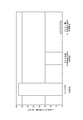
- (A) is a manufacturing process flowchart of the manufacturing method of the high cleanliness steel by one Embodiment of this invention
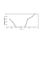
- (B) is a manufacturing process flowchart of the manufacturing method of the high cleanliness steel by a comparative example. It is an example of Ca concentration transition in the molten steel in the manufacturing processes of Comparative Methods 1 and 2 and the method of the present invention.
- (A) is an investigation of the average composition of CaO—MgO—Al 2 O 3 inclusions in a plurality of charges in molten steel samples taken after RH treatment and before Ca addition in Comparative Methods 1 and 2 and the method of the present invention.
- the results (B) are the results of investigating the average composition of CaO—MgO—Al 2 O 3 inclusions in molten steel samples collected after the addition of Ca in each charge of (A).
- the number of CaO—MgO—Al 2 O 3 inclusions having a diameter of 5 ⁇ m or more in the molten steel sample collected after the addition of Ca was investigated. It is a graph which shows the relationship between an atomic concentration ratio (ACR) parameter
- ACR atomic concentration ratio
- SSC stress corrosion cracking
- a method for producing a high cleanliness steel includes a step of adding a deoxidizer to molten steel in a converter and deoxidizing the molten steel, and a flux containing CaO in the molten steel. And a ladle refining step for desulfurizing the molten steel using a ladle furnace, a step for subjecting the molten steel to vacuum degassing using a vacuum degassing device, and then a Ca-containing metal in the molten steel. And a step of continuously casting the molten steel.
- a killed steel treatment in which a deoxidizer such as Si or Al is added in a converter, and for example, as shown in FIG.
- a rimmed steel treatment in which a deoxidizer such as Si or Al is added during ladle refining after furnace refining or during vacuum degassing.
- killed steel treatment is employed as the deoxidation treatment.
- the Ca concentration in the molten steel cannot be reduced to 0.0004% or less between the converter and the vacuum degassing treatment, and the inclusion composition after the addition of Ca is 1600.
- the liquid phase composition range cannot be controlled within the temperature range, and many large inclusions having a diameter of 5 ⁇ m or more are generated. This causes a problem of nozzle clogging and a problem that sufficient SSC resistance cannot be obtained.
- the deoxidation treatment can be performed by a general method of adding a deoxidizer such as Si or Al to molten steel.
- the deoxidation product formed by the deoxidation treatment is Al 2 O 3 (alumina).
- the addition composition after addition of Ca cannot be stably controlled within the 1600 ° C. liquid phase composition range, and many large inclusions having a diameter of 5 ⁇ m or more are generated. This causes a problem of nozzle clogging and a problem that sufficient SSC resistance cannot be obtained.
- the interval between Si addition and Al addition in the deoxidation treatment is not particularly limited, but is preferably 1 minute or more and 10 minutes or less. If the interval is less than 1 minute, the effects of the present invention may not be sufficiently obtained, and if the interval exceeds 10 minutes, it may grow into a giant SiO 2 —MnO (—CaO) oxide. Because there is.
- the ladle refining process includes a heating and stirring process in which gas is introduced into the molten steel while the molten steel is heated by arc discharge using a ladle furnace (LF).
- a flux containing CaO is added to the molten steel to perform a desulfurization treatment.
- As the flux quick lime (CaO) alone or a mixture of quick lime and Al 2 O 3 or SiO 2 which is a hatching accelerator of CaO can be used.
- the vacuum degassing treatment can be performed using a general apparatus such as an RH vacuum degassing apparatus, for example.
- the processing time for the ladle refining process and the vacuum degassing process is not particularly limited, and may be appropriately determined according to the O and S contents before the treatment with respect to the target O and S contents.
- the processing time of the pot refining process is about 30 to 60 minutes, and the processing time of the vacuum degassing process is about 10 to 40 minutes.
- the composition of the molten steel is finally adjusted to the target component composition by adding the alloy in the vacuum degassing process, but a large amount of Mn and Si components are added at the same time as the deoxidizer Al. Thereafter, it is generally added in several times so as to become a target component until ladle refining or vacuum degassing treatment.
- additional Si when additional Si is added for component adjustment, it is performed before the first half of the ladle refining process and not performed in the second half of the ladle refining process and the vacuum degassing process. is important. It is also preferable not to add additional Si after the ladle refining process so that the target Si content is satisfied only by Si addition performed before Al addition in the converter. Thereby, the Ca concentration in the molten steel from the converter to the vacuum degassing step can be continuously reduced to a low concentration of 4 ppm or less, and it becomes possible to produce a high cleanliness steel having better SSC resistance.
- the Ca addition method is not particularly defined, a method of adding a massive alloy having a content of Ca: 70% by mass and Si: 30% by mass or a wire wrapped with Fe hoop into molten steel is generally used. Yes. Since the Ca alloy reacts violently with the molten steel, it is easy to form molten steel re-oxide during the addition, and it is preferable to complete the argon seal during the addition.
- Ca addition after the vacuum degassing treatment may be performed subsequently to the vacuum degassing treatment in the ladle of the RH vacuum degassing apparatus, but after transferring the molten steel to a ladle dedicated for Ca treatment separately, It is preferable to add Ca to molten steel in the ladle.
- the treatment time of the LF process was 30 minutes, and after 10 minutes, 1.8 kg / ton-steel FeSi alloy was added as additional Si for component adjustment. Si was not added in the latter half of the LF process and in the RH process. After the RH process, Ca was added to the molten steel.
- Comparative method 1 Steel was melted in the same manner as in the method of the present invention except that the order of Al addition and Si addition in the converter was reversed. That is, in Comparative Method 1, the converter processing time was set to 60 minutes, 3.7 kg / ton-steel Al was added after 50 minutes, and 2.2 kg / ton-steel FeSi alloy was added 3 minutes later. .
- the processing time of the LF process was 45 minutes, and after 5 minutes, 2.2 kg / ton-steel FeSi alloy as deoxidizer Si was charged simultaneously with 3.5 kg / ton-steel Al. Further, an additional FeSi alloy was added for component adjustment at a timing of 2 minutes from the start of the RH treatment. After the RH process, Ca was added to the molten steel.
- the inventors of the present invention collected molten steel samples for each of the manufacturing processes and investigated the molten steel composition, the amount of inclusions, and the inclusion composition.
- the component analysis of the molten steel was performed by cantback rapid analysis.
- the inclusion investigation was carried out using a PSEM apparatus manufactured by ASPEX. Specifically, first, a molten steel sample was taken from a depth position of 2 m or more from the bath surface, and resin embedding and polishing were performed to prepare a sample for SEM observation. The sample was subjected to SEM observation, and the composition was determined by EDX for all inclusions having an inclusion diameter of 5 ⁇ m or more in a 15 ⁇ 15 mm visual field, and the average was calculated.
- the inclusion cross-sectional shape has anisotropy, the square diameter of the product of the major axis and the minor axis of the ellipse surrounding the section was taken as the inclusion diameter.
- the reaction of the oxide and the element entering from the slag with the deoxidizer (Al, Si, Mn, etc.), and the strong deoxidation element (Ca, Mg, Ti, etc.) contained in the alloy Changes under the influence.
- Ca treatment is finally performed for the purpose of suppressing MnS inclusions generated during solidification, and an oxide or CaS-based sulfide having a high CaO content is formed.
- Addition of Si is generally performed by adding an FeSi alloy to adjust the Si component.
- a general FeSi alloy inevitably contains about 0.3 to 1.5% of the Ca component, and a small amount of Ca component is added to the molten steel due to the addition of Si. CaO—Al 2 O 3 System inclusions will be generated.
- an alloy such as a SiMn alloy or Si scrap within a range not exceeding the allowable amount of other components including Mn.
- the Ca treatment is carried out mainly by introducing a CaSi alloy into the ladle after vacuum degassing, and is generally introduced so that Ca becomes 10 ppm or more in the molten steel.
- the CaO—MgO—Al 2 O 3 inclusions described above become CaO—Al 2 O 3 inclusions or CaS sulfides with a small MgO content.
- FIG. 2 shows the transition of Ca concentration in molten steel in Comparative Methods 1 and 2 and the method of the present invention.
- Comparative Method 1 the average value of 22 charges was plotted, and for the method of the present invention and Comparative Method 2, the average value of 5 charges was plotted.
- the Ca analysis value before the addition of Ca is as low as 4 ppm or less, whereas in Comparative methods 1 and 2, the Ca analysis value varies greatly from 5 to 15 ppm.
- FIG. 3 (A) is a result of investigating the average composition of CaO—MgO—Al 2 O 3 inclusions in molten steel samples collected after RH treatment and before Ca addition by multiple charges
- FIG. 3 (B) FIG. 3A is a result of investigating the average composition of CaO—MgO—Al 2 O 3 inclusions in a molten steel sample collected by tundish after adding Ca in each charge of FIG.
- the amount of Ca added was determined so that the inclusion composition after Ca addition would be in the liquid phase range at 1600 ° C. in the tundish stage, and Ca addition was performed.
- FIGS. 3 (A) and 3 (B) in the case of rimmed steel (Comparative Method 1), the average composition of inclusions before Ca treatment is caused by Ca that is considered to be caused by the FeSi alloy. It can be seen that the inclusion composition already contains many CaO—Al 2 O 3 .
- Si is added after addition of Al in killed steel
- the change to CaO—Al 2 O 3 inclusions progresses before Ca treatment, and the inclusion composition has a large variation. It could be confirmed.
- the inclusion composition before Ca addition is 10 to 20 wt% CaO mainly composed of MgO—Al 2 O 3 component. It was confirmed that the composition was uniform with very little variation. As a result, the inclusion composition of the sample collected from the tundish after the Ca treatment could be controlled to the 1600 ° C. liquid phase range.
- Comparative Methods 1 and 2 it was found that CaO—Al 2 O 3 inclusions having a high CaO composition with a large compositional variation and a high melting point were generated.
- the purpose of setting the average composition of inclusions in the tundish stage to the 1600 ° C. liquid phase range is as follows. (1) When CaO—Al 2 O 3 inclusions (3CaO ⁇ Al 2 O 3 to CaO + CaS) with high CaO concentration accompanied by CaS precipitation at the molten steel stage, the temperature drops in the subsequent tundish to mold immersion nozzle Sometimes nozzle clogging due to CaS is likely to occur. In addition, the inclusions that have become large due to aggregation drop off from the nozzle adhering location and are taken into the slab, and the deterioration of HIC resistance and SSC resistance becomes significant.
- the result of investigating the inclusion cleanliness of the sample collected with the tundish used in FIG. 3 (B) is shown in FIG. It was confirmed that the number of inclusions having a diameter of 5 ⁇ m or more was significantly improved in the method of the present invention compared to Comparative Methods 1 and 2.
- the average composition of inclusions after the addition of Ca could be controlled within the liquid phase range of 1600 ° C., which is considered to be due to the progress of inclusion floating removal.
- the appropriate range of the Ca addition amount during the Ca treatment was determined by investigating the Ca addition conditions and the results of the sulfide stress corrosion cracking (SSC) test in advance.
- the relationship between the atomic concentration ratio (ACR value) in the tundish when Ca is added after the vacuum degassing treatment (RH) and the rejection rate of the SSC test is shown in FIG.
- ACR value the atomic concentration ratio
- RH vacuum degassing treatment
- ACR atomic concentration ratio
- the ACR value is an index used to control the composition of MnS sulfide crystallized during solidification, CaS sulfide generated when Ca is excessively added, CaO oxide, and calcium aluminate inclusion (CaO—Al 2 O 3 ). It is. In general, it is known that ACR ⁇ 1.0 is effective in suppressing MnS sulfide generation, and that ACR ⁇ 3.0 can suppress CaO—CaS inclusion generation caused by excessive Ca addition. Yes.
- the composition of the MgO—CaO—Al 2 O 3 inclusions before Ca addition is controlled to a state with less variation, and the subsequent oxide composition and sulfide composition are controlled more accurately. It becomes possible. It is also possible to prevent clogging due to inclusions in the tundish immersion nozzle and to sufficiently suppress the formation of inclusions such as oxides and sulfides that are harmful to the SSC resistance. By applying the present invention, it is possible to manufacture a steel pipe excellent in SSC resistance without blocking due to inclusions in the immersion nozzle, and it is possible to achieve manufacturing cost reduction and yield stabilization.
- Table 1 shows the form of steel exit (killed steel and rimmed steel), the time of FeSi alloy addition, the Ca concentration in the molten steel before Ca treatment, the molten steel composition in the tundish after Ca treatment, and the ACR value.
- the converter processing time was 60 minutes.
- Si and Al were added to the molten steel in the converter for deoxidation treatment.
- the order of addition is shown in Table 1. In the example in which Al was added after FeSi was added, 2.2 kg / ton-steel FeSi alloy was added after 50 minutes from the start of the converter process, and 3.5 kg / ton-steel Al was added 5 minutes later. did.
- a CaO—Al 2 O 3 —SiO 2 flux was added to the molten steel, and a ladle refining process (desulfurization treatment) using LF was performed.
- the processing time of the LF process was 45 minutes.
- Si was added in the “first half of LF”
- Si was added 5 minutes after the start of the LF treatment.
- Si was added 30 minutes after the start of the LF treatment.
- the clogging situation was determined from the opening (hereinafter referred to as SN opening) of the sliding nozzle above the immersion nozzle for pouring molten steel into the mold from the tundish. That is, when the cross-sectional area of the flow path of the immersion nozzle becomes smaller due to the blockage, the SN opening degree approaches 100% by the automatic control function of the mold surface level. Under the present casting conditions, the operation with the SN opening of 60 to 70% is a stable casting state, but when the nozzle clogging occurs, the SN opening rapidly increases to 80 to 100%. Therefore, it was determined that the nozzle blockage occurred when the SN opening was 80% or more.
- Levels A, B, and C satisfied all the conditions of the present invention, and the SSC resistance and the degree of blockage of the immersion nozzle were good.
- Level D is an invention example where ACR value is below the lower limit of the preferred range, the clogging of the immersion nozzle due to the inclusions of CaO weight ratio lower high melting CaO ⁇ 6Al 2 O 3 ⁇ CaO ⁇ 2Al 2 O 3 composition The SSC test results were slightly worsened.
- Level E is an invention example in which the ACR value exceeded the upper limit of the preferred range, and the SSC test result decreased to 50% (3 out of 6 samples were broken) due to an increase in CaO-CaS inclusions.
- Level F is a comparative example in which the FeSi addition timing does not satisfy the conditions of the present invention, and the Ca concentration before Ca treatment also exceeded the upper limit of the preferred range, so the SSC test result was 33% (4 out of 6 samples were Rupture).
- Level G was the same as Level F.
- Levels H to L are rimmed steel (non-deoxidized steel), a comparative example that does not satisfy the FeSi addition timing, and the Ca concentration before Ca treatment is high, so the SSC test result was low.
- Level M is a comparative example in which the order of introduction of FeSi and Al does not satisfy the conditions of the present invention, and the Ca concentration before Ca treatment is also high, so the results of the SSC test did not reach levels A, B, and C.
Landscapes
- Chemical & Material Sciences (AREA)
- Engineering & Computer Science (AREA)
- Materials Engineering (AREA)
- Metallurgy (AREA)
- Organic Chemistry (AREA)
- Mechanical Engineering (AREA)
- Manufacturing & Machinery (AREA)
- Treatment Of Steel In Its Molten State (AREA)
Abstract
Description
-0.005≦(Ca/40-S/32)×sol.Al×T.[O]×1000000≦0.0042
[1]転炉内で溶鋼にSiを添加した後にAlを添加して、前記溶鋼に脱酸処理を施す工程と、
前記溶鋼にCaOを含有するフラックスを添加して、レードルファーネスを用いて前記溶鋼に脱硫処理を施す取鍋精錬工程と、
その後、真空脱ガス装置により前記溶鋼に真空脱ガス処理を施す工程と、
その後、前記溶鋼にCa含有金属を添加する工程と、
その後、前記溶鋼を連続鋳造する工程と、
を有し、
前記取鍋精錬工程では前記溶鋼にSiを添加しないか、
前記溶鋼の成分を調整するための追加Siを添加する場合には、前記取鍋精錬工程の処理期間中の前半に添加し、前記取鍋精錬工程の処理期間中の後半と前記真空脱ガス処理の期間中には添加しないことを特徴とする高清浄度鋼の製造方法。
下記の(1)式を満たすように前記Ca含有金属の添加量を設定する、請求項1~3のいずれか一項に記載の高清浄度鋼の製造方法。
記
1.00≦{[%Ca]-(0.18+130×[%Ca])×[%O]}
/1.25/[%S]≦2.00 ・・・(1)
ここで
[%Ca]、[%O]、[%S]:タンディッシュ内での溶鋼中の各元素の濃度(質量%)
である。
(本発明法)
図1(A)に示すプロセスで、タンディッシュでの溶鋼の化学組成C:0.2-0.3%、Si:0.22-0.27%、Mn:0.4-0.6%、P:0.005-0.009%、S:0.0005-0.002%、sol.Al:0.03-0.1%、Ca:0-0.003%、O:0.0010-0.0020%、残部:Fe及び不可避的不純物の鋼を溶製した。転炉処理時間は60分間とし、50分経過時に2.2kg/ton-steelのFeSi合金を添加し、その5分後に3.5kg/ton-steelのAlを添加した。LFプロセスの処理時間は30分間とし、10分経過後に、成分調整用の追加Siとして1.8kg/ton-steelのFeSi合金を添加した。LFプロセスの後半とRHプロセスではSiは添加しなかった。RHプロセス後、溶鋼にCa添加を行った。
転炉でのAl添加とSi添加の順序を逆にした以外は、本発明法と同様にして、鋼を溶製した。すなわち、比較法1では、転炉処理時間を60分間とし、50分経過後に3.7kg/ton-steelのAlを添加し、その3分後に2.2kg/ton-steelのFeSi合金を添加した。
図1(B)に例示するようなリムド出鋼のプロセスで、タンディッシュでの溶鋼の化学組成C:0.2-0.3%、Si:0.22-0.27%、Mn:0.4-0.6%、P:0.005-0.009%、S:0.0005-0.002%、sol.Al:0.03-0.1%、Ca:0-0.003%、O:0.0010-0.0020%、残部:Fe及び不可避的不純物の鋼を溶製した。すなわち、転炉では脱酸剤としてSi及びAlを添加しなかった。その後、LFプロセスの処理時間は45分間とし、5分経過後に脱酸剤Siとして2.2kg/ton-steelのFeSi合金を、3.5kg/ton-steelのAlと同時に投入した。また、RH処理の開始から2分のタイミングで、追加のFeSi合金を成分調整のために添加した。RHプロセス後、溶鋼にCa添加を行った。
(1)Al添加前:Fe2O3(+MnO+SiO2+CaO・・・)
(2)Al添加後:Al2O3介在物
(3)CaOフラックス添加による脱硫処理中:MgO-Al2O3系介在物
(4)Si添加:CaO-Al2O3系介在物が増加
(5)取鍋精錬(LF)後、真空脱ガス(RH)後:CaO-MgO-Al2O3系介在物
(6)Ca処理後:CaO-Al2O3系介在物+CaS
(1)溶鋼段階でCaS析出を伴う高CaO濃度のCaO-Al2O3介在物(3CaO・Al2O3~CaO+CaS)となった場合、その後のタンディッシュ~鋳型での浸漬ノズルにおいて温度低下時にCaS起因のノズル閉塞が発生しやすい。また、凝集により巨大化した介在物がノズル付着箇所より脱落して鋳片に取り込まれ、耐HIC性及び耐SSC性の劣化が顕著となる。
(2)溶鋼段階での介在物の平均組成が液相介在物組成(1600℃液相範囲)よりも低CaO濃度のCaO-Al2O3介在物組成(特にCaO・6Al2O3~CaO・2Al2O3)となった場合にも、ノズル閉塞が生じやすくなる。また、凝固時に有害なMnSが析出しやすくなり、耐HIC性及び耐SSC性の劣化が顕著となる。
したがってCaO・Al2O3~3CaO・Al2O3の介在物組成、好ましくは12CaO・7Al2O3介在物組成に制御することが重要である。
原子濃度比(ACR)は下記の式により規定した。
ACR={[%Ca]-(0.18+130×[%Ca])×[%O]}
/1.25/[%S]
[%Ca]、[%O]、[%S]:タンディッシュ内での溶鋼中の各元素の濃度(質量%)
耐SSC試験は、1気圧の硫化水素が飽和したNACE試験液中でサンプルに最小降伏応力の85%の応力を付与して単軸引張試験を720時間実施した。なお、SSC試験に供試したサンプルは熱処理により硬度をHRC=27にそろえた。SSC試験は各条件6本のサンプルを実施し、720時間の満了時間に対して破断無で試験をクリアできた本数の比率を合格率として表1に示した。合格率100%の場合を、耐SSC性良好と判断する。
ノズル閉塞の判定方法としては、タンディッシュから鋳型に溶鋼を注入させる浸漬ノズルの上部のスライディングノズルの開度(以下、SN開度と記す)から閉塞状況を判定した。すなわち、浸漬ノズルの流路の断面積が閉塞により小さくなった場合には、鋳型内湯面レベルの自動制御機能により、SN開度は100%に近づいていく。今回の鋳造条件では、SN開度は60~70%での操業が安定鋳造状態であるが、ノズル閉塞が発生するとSN開度は80~100%に急増する。そこで、SN開度が80%以上となった場合をノズル閉塞発生と判断した。

Claims (4)
- 転炉内で溶鋼にSiを添加した後にAlを添加して、前記溶鋼に脱酸処理を施す工程と、
前記溶鋼にCaOを含有するフラックスを添加して、レードルファーネスを用いて前記溶鋼に脱硫処理を施す取鍋精錬工程と、
その後、真空脱ガス装置により前記溶鋼に真空脱ガス処理を施す工程と、
その後、前記溶鋼にCa含有金属を添加する工程と、
その後、前記溶鋼を連続鋳造する工程と、
を有し、
前記取鍋精錬工程では前記溶鋼にSiを添加しないか、
前記溶鋼の成分を調整するための追加Siを添加する場合には、前記取鍋精錬工程の処理期間中の前半に添加し、前記取鍋精錬工程の処理期間中の後半と前記真空脱ガス処理の期間中には添加しないことを特徴とする高清浄度鋼の製造方法。 - 前記追加Siの添加は、前記取鍋精錬工程の処理開始から10分以内に行う、請求項1に記載の高清浄度鋼の製造方法。
- 前記脱酸処理におけるSi添加とAl添加との間隔は、1分以上10分以下とする、請求項1又は2に記載の高清浄度鋼の製造方法。
- 前記真空脱ガス処理後かつ前記Ca含有金属添加前の前記溶鋼中のCa濃度が0.0004質量%以下であり、
下記の(1)式を満たすように前記Ca含有金属の添加量を設定する、請求項1~3のいずれか一項に記載の高清浄度鋼の製造方法。
記
1.00≦{[%Ca]-(0.18+130×[%Ca])×[%O]}/1.25/[%S]≦2.00 ・・・(1)
ここで
[%Ca]、[%O]、[%S]:タンディッシュ内での溶鋼中の各元素の濃度(質量%)
である。
Priority Applications (3)
| Application Number | Priority Date | Filing Date | Title |
|---|---|---|---|
| KR1020207028831A KR102410083B1 (ko) | 2018-03-23 | 2019-03-20 | 고세정도 강의 제조 방법 |
| EP19770761.5A EP3770280B1 (en) | 2018-03-23 | 2019-03-20 | Method for manufacturing high-purity steel |
| JP2019546944A JP6648866B1 (ja) | 2018-03-23 | 2019-03-20 | 高清浄度鋼の製造方法 |
Applications Claiming Priority (2)
| Application Number | Priority Date | Filing Date | Title |
|---|---|---|---|
| JP2018-057080 | 2018-03-23 | ||
| JP2018057080 | 2018-03-23 |
Publications (1)
| Publication Number | Publication Date |
|---|---|
| WO2019182056A1 true WO2019182056A1 (ja) | 2019-09-26 |
Family
ID=67987249
Family Applications (1)
| Application Number | Title | Priority Date | Filing Date |
|---|---|---|---|
| PCT/JP2019/011852 Ceased WO2019182056A1 (ja) | 2018-03-23 | 2019-03-20 | 高清浄度鋼の製造方法 |
Country Status (4)
| Country | Link |
|---|---|
| EP (1) | EP3770280B1 (ja) |
| JP (1) | JP6648866B1 (ja) |
| KR (1) | KR102410083B1 (ja) |
| WO (1) | WO2019182056A1 (ja) |
Cited By (4)
| Publication number | Priority date | Publication date | Assignee | Title |
|---|---|---|---|---|
| CN114292982A (zh) * | 2022-01-04 | 2022-04-08 | 马鞍山钢铁股份有限公司 | 一种新能源汽车电池壳用钢砂眼缺陷的控制方法 |
| CN114318108A (zh) * | 2021-12-02 | 2022-04-12 | 包头钢铁(集团)有限责任公司 | 一种超低铝高纯工业纯铁生产方法 |
| CN116770009A (zh) * | 2023-07-19 | 2023-09-19 | 中国第一重型机械股份公司 | 一种大型碳锰钢管板钢锭及其生产方法 |
| CN118345299A (zh) * | 2024-04-19 | 2024-07-16 | 华北理工大学 | 一种大于1000MPa低碳高铝耐磨钢连铸坯的生产方法 |
Citations (4)
| Publication number | Priority date | Publication date | Assignee | Title |
|---|---|---|---|---|
| JP2002060893A (ja) | 2000-08-18 | 2002-02-28 | Sumitomo Metal Ind Ltd | 耐硫化物応力腐食割れ性に優れた油井用鋼とその製造方法 |
| JP2010209372A (ja) | 2009-03-09 | 2010-09-24 | Jfe Steel Corp | 耐硫化物腐食割れ性に優れた清浄鋼の製造方法 |
| JP2011089180A (ja) | 2009-10-23 | 2011-05-06 | Sumitomo Metal Ind Ltd | 高強度・高耐食性油井管用鋼材の溶製方法 |
| JP2017170487A (ja) * | 2016-03-24 | 2017-09-28 | 新日鐵住金株式会社 | 高炭素溶鋼の連続鋳造方法 |
Family Cites Families (4)
| Publication number | Priority date | Publication date | Assignee | Title |
|---|---|---|---|---|
| JP3250459B2 (ja) * | 1996-06-25 | 2002-01-28 | 住友金属工業株式会社 | 溶接部の低温靱性に優れた耐hic鋼およびその製造方法 |
| JPH10237533A (ja) * | 1997-02-27 | 1998-09-08 | Sumitomo Metal Ind Ltd | 耐hic鋼の製造方法 |
| JP4571994B2 (ja) * | 2008-07-15 | 2010-10-27 | 新日本製鐵株式会社 | 低炭素鋼の連続鋳造方法 |
| CN104018091B (zh) * | 2014-06-18 | 2016-11-23 | 江苏省沙钢钢铁研究院有限公司 | 一种钢筋及其制备方法 |
-
2019
- 2019-03-20 WO PCT/JP2019/011852 patent/WO2019182056A1/ja not_active Ceased
- 2019-03-20 KR KR1020207028831A patent/KR102410083B1/ko active Active
- 2019-03-20 JP JP2019546944A patent/JP6648866B1/ja active Active
- 2019-03-20 EP EP19770761.5A patent/EP3770280B1/en active Active
Patent Citations (4)
| Publication number | Priority date | Publication date | Assignee | Title |
|---|---|---|---|---|
| JP2002060893A (ja) | 2000-08-18 | 2002-02-28 | Sumitomo Metal Ind Ltd | 耐硫化物応力腐食割れ性に優れた油井用鋼とその製造方法 |
| JP2010209372A (ja) | 2009-03-09 | 2010-09-24 | Jfe Steel Corp | 耐硫化物腐食割れ性に優れた清浄鋼の製造方法 |
| JP2011089180A (ja) | 2009-10-23 | 2011-05-06 | Sumitomo Metal Ind Ltd | 高強度・高耐食性油井管用鋼材の溶製方法 |
| JP2017170487A (ja) * | 2016-03-24 | 2017-09-28 | 新日鐵住金株式会社 | 高炭素溶鋼の連続鋳造方法 |
Non-Patent Citations (1)
| Title |
|---|
| See also references of EP3770280A4 |
Cited By (4)
| Publication number | Priority date | Publication date | Assignee | Title |
|---|---|---|---|---|
| CN114318108A (zh) * | 2021-12-02 | 2022-04-12 | 包头钢铁(集团)有限责任公司 | 一种超低铝高纯工业纯铁生产方法 |
| CN114292982A (zh) * | 2022-01-04 | 2022-04-08 | 马鞍山钢铁股份有限公司 | 一种新能源汽车电池壳用钢砂眼缺陷的控制方法 |
| CN116770009A (zh) * | 2023-07-19 | 2023-09-19 | 中国第一重型机械股份公司 | 一种大型碳锰钢管板钢锭及其生产方法 |
| CN118345299A (zh) * | 2024-04-19 | 2024-07-16 | 华北理工大学 | 一种大于1000MPa低碳高铝耐磨钢连铸坯的生产方法 |
Also Published As
| Publication number | Publication date |
|---|---|
| JPWO2019182056A1 (ja) | 2020-04-30 |
| KR102410083B1 (ko) | 2022-06-16 |
| JP6648866B1 (ja) | 2020-02-14 |
| EP3770280A1 (en) | 2021-01-27 |
| EP3770280A4 (en) | 2021-01-27 |
| KR20200124753A (ko) | 2020-11-03 |
| EP3770280B1 (en) | 2023-05-10 |
Similar Documents
| Publication | Publication Date | Title |
|---|---|---|
| CN101784680B (zh) | 抗硫性能优异的钢管用钢的制造方法 | |
| CA2798852C (en) | Steel for steel tube with excellent sulfide stress cracking resistance | |
| JP6648866B1 (ja) | 高清浄度鋼の製造方法 | |
| CN108531807B (zh) | 一种厚壁大口径x80m管线洁净钢及冶炼方法 | |
| JP6786964B2 (ja) | 硫黄添加鋼の連続鋳造ノズルの閉塞防止方法 | |
| WO2014061784A1 (ja) | 疲労特性に優れる肌焼鋼 | |
| WO2014061782A1 (ja) | 疲労特性に優れる高周波焼入れ用鋼 | |
| JP7031634B2 (ja) | 耐サワー鋼材の製造方法 | |
| CN108893683A (zh) | 一种抗硫管线钢及其生产方法 | |
| KR102565782B1 (ko) | 용강으로의 Ca 첨가 방법 | |
| JP7260731B2 (ja) | 高清浄鋼とその精錬方法 | |
| JP6579147B2 (ja) | 高清浄度鋼の製造方法 | |
| CN102015156B (zh) | 低碳钢铸片的制造方法 | |
| JP5056826B2 (ja) | 連続鋳造用鋼およびその製造方法 | |
| JP2003160838A (ja) | 継目無鋼管とその製造方法 | |
| JP2020084250A (ja) | 継目無鋼管用鋼材 | |
| JP7492118B2 (ja) | 延伸性MnSが少ない鋼材、鋼鋳片、およびそれらの製造方法 | |
| KR101091931B1 (ko) | 칼슘 처리강의 제조 방법 | |
| JP6888275B2 (ja) | 硫黄添加鋼の製造方法 | |
| JP6086036B2 (ja) | 溶接熱影響部靱性に優れた厚板鋼材とその溶製方法 | |
| JP2976849B2 (ja) | 耐hic鋼の製造方法 | |
| RU2375463C2 (ru) | Проволока для внепечной обработки металлургических расплавов | |
| KR20170046216A (ko) | 용강 내 개재물 저감 장치 및 청정도가 향상된 스테인리스강의 제조 방법 | |
| CN115702253A (zh) | 作为高疲劳强度钢的原料的铸片的制造方法 | |
| JP5135923B2 (ja) | Sus301のバネ用オーステナイト系ステンレス鋼 |
Legal Events
| Date | Code | Title | Description |
|---|---|---|---|
| ENP | Entry into the national phase |
Ref document number: 2019546944 Country of ref document: JP Kind code of ref document: A |
|
| 121 | Ep: the epo has been informed by wipo that ep was designated in this application |
Ref document number: 19770761 Country of ref document: EP Kind code of ref document: A1 |
|
| NENP | Non-entry into the national phase |
Ref country code: DE |
|
| ENP | Entry into the national phase |
Ref document number: 20207028831 Country of ref document: KR Kind code of ref document: A |
|
| WWE | Wipo information: entry into national phase |
Ref document number: 2019770761 Country of ref document: EP |