WO2019186783A1 - 流量計測装置及び流量計測方法 - Google Patents
流量計測装置及び流量計測方法 Download PDFInfo
- Publication number
- WO2019186783A1 WO2019186783A1 PCT/JP2018/012821 JP2018012821W WO2019186783A1 WO 2019186783 A1 WO2019186783 A1 WO 2019186783A1 JP 2018012821 W JP2018012821 W JP 2018012821W WO 2019186783 A1 WO2019186783 A1 WO 2019186783A1
- Authority
- WO
- WIPO (PCT)
- Prior art keywords
- flow rate
- differential pressure
- flow
- fluid
- columnar member
- Prior art date
- Legal status (The legal status is an assumption and is not a legal conclusion. Google has not performed a legal analysis and makes no representation as to the accuracy of the status listed.)
- Ceased
Links
Images




Classifications
-
- G—PHYSICS
- G01—MEASURING; TESTING
- G01F—MEASURING VOLUME, VOLUME FLOW, MASS FLOW OR LIQUID LEVEL; METERING BY VOLUME
- G01F1/00—Measuring the volume flow or mass flow of fluid or fluent solid material wherein the fluid passes through a meter in a continuous flow
- G01F1/05—Measuring the volume flow or mass flow of fluid or fluent solid material wherein the fluid passes through a meter in a continuous flow by using mechanical effects
- G01F1/34—Measuring the volume flow or mass flow of fluid or fluent solid material wherein the fluid passes through a meter in a continuous flow by using mechanical effects by measuring pressure or differential pressure
- G01F1/36—Measuring the volume flow or mass flow of fluid or fluent solid material wherein the fluid passes through a meter in a continuous flow by using mechanical effects by measuring pressure or differential pressure the pressure or differential pressure being created by the use of flow constriction
- G01F1/40—Details of construction of the flow constriction devices
-
- G—PHYSICS
- G01—MEASURING; TESTING
- G01F—MEASURING VOLUME, VOLUME FLOW, MASS FLOW OR LIQUID LEVEL; METERING BY VOLUME
- G01F1/00—Measuring the volume flow or mass flow of fluid or fluent solid material wherein the fluid passes through a meter in a continuous flow
- G01F1/05—Measuring the volume flow or mass flow of fluid or fluent solid material wherein the fluid passes through a meter in a continuous flow by using mechanical effects
- G01F1/34—Measuring the volume flow or mass flow of fluid or fluent solid material wherein the fluid passes through a meter in a continuous flow by using mechanical effects by measuring pressure or differential pressure
- G01F1/36—Measuring the volume flow or mass flow of fluid or fluent solid material wherein the fluid passes through a meter in a continuous flow by using mechanical effects by measuring pressure or differential pressure the pressure or differential pressure being created by the use of flow constriction
- G01F1/40—Details of construction of the flow constriction devices
- G01F1/46—Pitot tubes
-
- G—PHYSICS
- G01—MEASURING; TESTING
- G01F—MEASURING VOLUME, VOLUME FLOW, MASS FLOW OR LIQUID LEVEL; METERING BY VOLUME
- G01F1/00—Measuring the volume flow or mass flow of fluid or fluent solid material wherein the fluid passes through a meter in a continuous flow
- G01F1/05—Measuring the volume flow or mass flow of fluid or fluent solid material wherein the fluid passes through a meter in a continuous flow by using mechanical effects
- G01F1/34—Measuring the volume flow or mass flow of fluid or fluent solid material wherein the fluid passes through a meter in a continuous flow by using mechanical effects by measuring pressure or differential pressure
-
- G—PHYSICS
- G01—MEASURING; TESTING
- G01F—MEASURING VOLUME, VOLUME FLOW, MASS FLOW OR LIQUID LEVEL; METERING BY VOLUME
- G01F1/00—Measuring the volume flow or mass flow of fluid or fluent solid material wherein the fluid passes through a meter in a continuous flow
- G01F1/05—Measuring the volume flow or mass flow of fluid or fluent solid material wherein the fluid passes through a meter in a continuous flow by using mechanical effects
- G01F1/34—Measuring the volume flow or mass flow of fluid or fluent solid material wherein the fluid passes through a meter in a continuous flow by using mechanical effects by measuring pressure or differential pressure
- G01F1/36—Measuring the volume flow or mass flow of fluid or fluent solid material wherein the fluid passes through a meter in a continuous flow by using mechanical effects by measuring pressure or differential pressure the pressure or differential pressure being created by the use of flow constriction
- G01F1/363—Measuring the volume flow or mass flow of fluid or fluent solid material wherein the fluid passes through a meter in a continuous flow by using mechanical effects by measuring pressure or differential pressure the pressure or differential pressure being created by the use of flow constriction with electrical or electro-mechanical indication
-
- G—PHYSICS
- G01—MEASURING; TESTING
- G01F—MEASURING VOLUME, VOLUME FLOW, MASS FLOW OR LIQUID LEVEL; METERING BY VOLUME
- G01F25/00—Testing or calibration of apparatus for measuring volume, volume flow or liquid level or for metering by volume
- G01F25/10—Testing or calibration of apparatus for measuring volume, volume flow or liquid level or for metering by volume of flowmeters
-
- G—PHYSICS
- G01—MEASURING; TESTING
- G01F—MEASURING VOLUME, VOLUME FLOW, MASS FLOW OR LIQUID LEVEL; METERING BY VOLUME
- G01F7/00—Volume-flow measuring devices with two or more measuring ranges; Compound meters
- G01F7/005—Volume-flow measuring devices with two or more measuring ranges; Compound meters by measuring pressure or differential pressure, created by the use of flow constriction
-
- G—PHYSICS
- G01—MEASURING; TESTING
- G01F—MEASURING VOLUME, VOLUME FLOW, MASS FLOW OR LIQUID LEVEL; METERING BY VOLUME
- G01F1/00—Measuring the volume flow or mass flow of fluid or fluent solid material wherein the fluid passes through a meter in a continuous flow
- G01F1/05—Measuring the volume flow or mass flow of fluid or fluent solid material wherein the fluid passes through a meter in a continuous flow by using mechanical effects
- G01F1/34—Measuring the volume flow or mass flow of fluid or fluent solid material wherein the fluid passes through a meter in a continuous flow by using mechanical effects by measuring pressure or differential pressure
- G01F1/36—Measuring the volume flow or mass flow of fluid or fluent solid material wherein the fluid passes through a meter in a continuous flow by using mechanical effects by measuring pressure or differential pressure the pressure or differential pressure being created by the use of flow constriction
- G01F1/40—Details of construction of the flow constriction devices
- G01F1/42—Orifices or nozzles
Definitions
- the present invention relates to a flow rate measuring device and a flow rate measuring method. More specifically, a measuring instrument that measures a differential pressure between a first pressure in the first pressure receiving portion of the tubular body through which the fluid flows and a second pressure in the second pressure receiving portion of the tubular body, and the fluid from the measured differential pressure
- the present invention relates to a flow rate measuring device and a flow rate measuring method provided with a processing machine that calculates the flow rate of the flow.
- a device as described in Patent Document 1 is known as a flow rate measuring device as described above.
- This apparatus measures the flow rate of the fluid using the differential pressure between the static pressure measured by the static pressure measurement hole provided in the conduction path and the wake pressure measured by the wake pressure detection tube.
- the fluid flow includes a laminar flow region and a turbulent flow region, and a transition region that changes from the laminar flow region to the turbulent flow region therebetween.
- the flow rate is not calculated in consideration of such a fluid state, and further improvement in measurement accuracy has been desired.
- an object of the present invention is to provide a flow rate measuring device and a flow rate measuring method capable of accurately measuring a flow rate not only in a turbulent flow region but also in a transition region from a laminar flow region. To do.
- the flow rate measuring device is characterized in that a differential pressure between a first pressure at a first pressure receiving portion of a tubular body through which a fluid flows and a second pressure at a second pressure receiving portion of the tubular body.
- the processor has a plurality of known flow rates and a measured differential pressure with respect to the plurality of known flow rates.
- a differential pressure determination unit that selects one of two parameter sets generated by comparing the measured differential pressure with the reference differential pressure, and the selected parameter set and the measured differential pressure are Substitute into flow rate calculation formula It is to have a flow rate calculation unit for calculating a flow rate of the fluid Te.
- the fluid flowing inside the tube has a laminar flow region where the viscous force is a smooth flow without a vortex, a turbulent region where the inertial force where various vortices are dominant, Between the laminar flow region and the turbulent flow region, there exists a transition region where viscous force and inertial force coexist.
- the differential pressure ⁇ P of the fluid is obtained by a flow rate calculation formula represented by a quadratic function of the flow rate Q in the above formula 1.
- c1 ⁇ ⁇ ⁇ Q is referred to as a viscosity term
- c2 ⁇ ⁇ ⁇ Q 2 is referred to as an inertia term.
- the laminar flow region and the turbulent region have different fluid flow conditions, and the dependence on the viscosity term and inertia term in the flow rate calculation formula is different.
- the reference differential pressure in the flow rate calculation formula of Formula 1 is obtained from a plurality of known flow rates and the measured differential pressures for the plurality of known flow rates, and the flow rate calculation formula Two parameter sets including the coefficients c1 to c3 are generated.
- the flow rate calculation formula at the reference pressure is the range corresponding to the range where laminar flow separation hardly occurs (when the flow rate is small) and the range where laminar flow separation occurs (when the flow rate is large). Since the coefficient of the flow rate calculation formula is generated in each range, a parameter set that is a coefficient corresponding to the state of fluid flow in the vicinity of the outer peripheral surface of the columnar member can be generated.
- one of the two parameter sets generated by comparing the measured differential pressure of the fluid to be measured and the reference differential pressure is selected, and the selected parameter set and the measured differential pressure are calculated as a flow rate. Since the flow rate of the fluid is calculated by substituting into the equation, the flow rate can be calculated based on the parameter corresponding to the state of the fluid to be measured, and the calculation accuracy is improved. In addition, since different parameters are generated with the reference differential pressure as a boundary, the calculation accuracy is improved in a region where the flow rate is small enough to include the above-described transition region and laminar flow region. Therefore, it is possible to accurately measure the flow rate not only in the turbulent flow region but also in the transition region from the laminar flow region.
- the said structure WHEREIN The said pipe body was equipped with the columnar member extended in the direction orthogonal to the flow direction of the said fluid inside, and the said 1st pressure receiving part was provided in the upstream of the said flow direction of the said columnar member.
- the columnar member has a streamline shape that is line symmetric with respect to the first plane passing through the center of the length along the flow direction, and the first measurement hole and the second measurement hole are symmetric with respect to the first plane. It is good to be arranged.
- the columnar member extending in the direction orthogonal to the fluid flow direction in the tube body exhibits a streamline shape that is axisymmetric with respect to the first plane passing through the center of the length along the flow direction. Laminar flow and turbulent flow are generated by the fluid flowing along the shape.
- a first measurement hole as a first pressure receiving portion is arranged upstream of the flow direction and a second measurement hole as a second pressure receiving portion is arranged symmetrically with respect to the first plane on the downstream side.
- the columnar member may be axisymmetric with respect to a second plane including the central axis of the tubular body and parallel to the extending direction of the columnar member.
- the columnar member may have an outer peripheral surface whose shape projected on a third plane orthogonal to the first plane and the second plane is defined by the following formulas 2 and 3.
- L 2 (K + r)
- d 2 (K (1 / cos ⁇ tan ⁇ ) + r) (O: origin, d: width of the columnar member, L: length of the columnar member in the flow direction, r: radius of the arc centered at a point a ⁇ K away from the origin O in the flow direction, ⁇ : center of the arc Corner / 2)
- the width d of the columnar member in the tube radial direction depends on the central angle of the arc.
- the length of the columnar member in the extending direction inside the tube is preferably smaller than the diameter of the tube.
- the first measurement hole and the second measurement hole may be located on the central axis of the tubular body. Therefore, since the differential pressure at the center where the pressure due to the fluid flowing through the pipe body is the highest is measured, the measurement accuracy of the flow rate is improved.
- the columnar member may be solid, and a tubular communication path communicating with a measuring instrument may be formed in each of the first measurement hole and the second measurement hole. By making it solid, it is possible to ensure measurement accuracy while ensuring strength (resistance) against the fluid.
- the fluid may be respiration.
- the flow measurement device according to the present invention can be implemented as, for example, a respiration measurement device.
- the fluid may be a medical gas.
- the first pressure receiving portion is a first opening provided in a tube wall of the tubular body, and the columnar member is the first opening.
- the second pressure receiving portion may be a second opening provided on the downstream side of the columnar member.
- the tube body includes an orifice for reducing the pipe line on the tube wall
- the first pressure receiving portion is a first opening provided in the tube wall upstream of the orifice in the fluid flow direction.
- the second pressure receiving part may be a second opening provided in the tube wall on the downstream side of the orifice in the fluid flow direction.
- the flow measurement method according to the present invention is characterized by the difference between the first pressure in the first pressure receiving portion of the tubular body through which the fluid flows and the second pressure in the second pressure receiving portion of the tubular body.
- a fluid having a known flow rate is caused to flow through the tube, and a plurality of known flow rates and a measured differential pressure with respect to the plurality of known flow rates are measured.
- the reference differential pressure in the flow rate calculation formula of the following formula 4 is obtained from the above, and two parameter sets including the coefficients c1 to c3 of the flow rate calculation formula are generated with the reference differential pressure as a boundary, and the fluid to be measured is defined as the pipe body. And select one of two parameter sets generated by comparing the measured differential pressure of the fluid to be measured and the reference differential pressure, and select the selected parameter set and the measured difference. Substituting pressure into the flow rate calculation formula It is to calculate the flow rate of the fluid Te.
- the flow rate measuring device and the flow rate measuring method according to the present invention it is possible to accurately measure the flow rate not only in the turbulent flow region but also in the transition region from the laminar flow region.
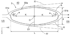
- FIG. 6 is a schematic diagram showing a correspondence relationship between a columnar member and first to third planes. It is a schematic diagram which shows the correspondence of a columnar member and Formula 2 and Formula 3.
- FIG. 5 is a graph schematically showing the relationship among a reference differential pressure ⁇ P, data groups A1 and A2, and parameter sets B1 and B2.
- FIG. 3 is a view corresponding to FIG. 2 according to another embodiment of the present invention.
- FIG. 3 is a view corresponding to FIG. 2B according to still another embodiment of the present invention.
- FIG. 3 is a view corresponding to FIG. 2B according to still another embodiment of the present invention.
- a flow rate measuring apparatus 1 roughly calculates a flow rate Q of a fluid from a measuring device 2 that measures a differential pressure ⁇ P in a tubular body 4 through which the fluid flows, and the measured differential pressure ⁇ P.
- the processing machine 3 to be provided.
- the fluid is human respiration.
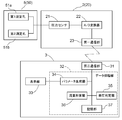
- the measuring instrument 2 measures a pressure sensor 21 that measures a first pressure in a first pressure receiving portion 51 a and a second pressure in a second pressure receiving portion 51 b described later, and a signal measured by the pressure sensor 21.
- An A / D converter 22 that converts digital data and a first communication unit 23 that transmits the digital data converted by the A / D converter 22 to the second communication unit 31 of the processor 3 are provided.
- the communication with the processor 3 uses wireless communication means such as Bluetooth (registered trademark), but data communication may be performed by wire.
- the processor 3 is subjected to data processing, a second communication unit 31 that receives digital data from the first communication unit 23, a data processing unit 32 that performs data processing of the received digital data, and And a display unit 33 for displaying data and the like.
- a second communication unit 31 that receives digital data from the first communication unit 23
- a data processing unit 32 that performs data processing of the received digital data
- a display unit 33 for displaying data and the like.
- portable terminals such as a tablet and a smart phone, and a personal computer (PC) can be used as the processing machine 3.
- the data processing unit 32 obtains a reference differential pressure ⁇ P ′, which will be described later, and sets two sets of parameter sets B including coefficients c1 to c3 of the flow rate calculation formula with the reference differential pressure ⁇ P ′ as a boundary.
- the setting unit 34, the differential pressure determination unit 35 that compares the measured differential pressure ⁇ P of the fluid to be measured and the reference differential pressure ⁇ P ′ and selects one of the two parameter sets, and the selected parameter set
- a flow rate calculation unit 36 for calculating the flow rate Q of the fluid by substituting the measured differential pressure ⁇ P into the flow rate calculation formula.
- the data processing unit 32 includes a storage unit 37 that stores received digital data, set parameters, calculated flow rate Q, and the like.
- the tubular body 4 is a circular tube attached through the housing 20.
- the tubular body 4 includes a columnar member 5 extending in a direction Z orthogonal to the fluid flow direction X in an interior 40 thereof.
- the columnar member 5 passes through the tube wall 41 and is fixed to the tube body 4 with the tip 53 abutting against the tube inner surface 41a.
- the columnar member 5 includes a first measurement hole 51 a as a first pressure receiving portion on the upstream side US of the columnar member 5 in the flow direction X and a downstream DS in the flow direction X. And a second measurement hole 51b as a second pressure receiving portion.
- These first and second measurement holes 51 a and 51 b are located on the central axis 42 of the tube body 4.
- the pressure of the fluid flowing in the circular pipe 40 is highest near the pipe shaft 42 on the upstream side US of the columnar member 5. Further, in the vicinity of the tube axis 42 of the downstream side DS, it is easily affected by a fine vacuum caused by turbulent flow. Accordingly, by positioning the first measurement hole 51a and the second measurement hole 51b on the central axis 42 of the tube body 4, the measured differential pressure ⁇ P is increased, and the flow rate Q calculated using the differential pressure ⁇ P is increased. Accuracy is improved.
- the first and second pressure receiving portions 51a and 51b for measuring the differential pressure ⁇ P are provided in the columnar member 5, for example, a conventional orifice flow meter provided with a throttle mechanism (orifice) or the back of the above-mentioned Patent Document 1 Unlike the pressure type differential pressure type flow meter, it is not necessary to provide the static pressure hole for measuring the static pressure in the tube wall 41 of the tube body 4. Therefore, the straight pipe region required before and after the pressure receiving portion 51 for measuring the differential pressure ⁇ P can be set to about the diameter D of the pipe body 4 (about 15 times the diameter D in the orifice flow meter, the back pressure type differential pressure type (About 4 times the diameter D for a flow meter). Accordingly, it is possible to reduce the size and weight of the flow rate measurement device so far, and in the example of the present embodiment, the total length of the tube body 4 can be shortened, and the measuring instrument 2 can be made compact.
- the columnar member 5 has a solid main body portion 50, and the tubular first and second continuous portions communicating with the first measurement hole 51a and the second measurement hole 51b, respectively. Passages 52a and 52b are formed.
- the pressure sensor 21 is connected to the other ends of the first and second communication passages 52a and 52b, and the differential pressure ⁇ P is measured.
- the columnar member 5 is axisymmetric with respect to a first plane S ⁇ b> 1 that is perpendicular to the central axis 42 of the tubular body 4 and passes through the center O having a length L along the flow direction X of the columnar member 5.
- a first plane S ⁇ b> 1 that is perpendicular to the central axis 42 of the tubular body 4 and passes through the center O having a length L along the flow direction X of the columnar member 5.
- the first measurement hole 51a and the second measurement hole 51b are arranged line-symmetrically with respect to the first plane S1.
- the columnar member 5 has bidirectionality with respect to the fluid flow direction X. Therefore, in the respiration as the fluid in the present embodiment, the flow direction X is opposite between exhalation and inspiration, but it is not necessary to change the apparatus itself or the parameter set B described later.
- the flow rate Q can be measured by measuring the differential pressure ⁇ P regardless of the fluid flow direction X.
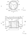
- the columnar member 5 is line-symmetric with respect to a second plane S2 including the central axis 42 of the tubular body 4 and parallel to the extending direction Z of the columnar member 5. Since it is line symmetric with respect to the second plane S2, as shown in FIG. 3, the columnar member 5 and the gap G1 between the columnar member 5 and the tube wall 41 are symmetric in the flow direction X view. Therefore, the pressure by the fluid applied to the columnar member 5 is substantially uniform on both sides of the second plane S2, and the durability of the columnar member 5 is improved.
- the shape projected on the third plane S3 orthogonal to the first plane S1 and the second plane S2 is defined by the above-described Expression 2 and Expression 3.
- the outer peripheral surface 50a is provided.
- the origin O is the center of the columnar member 5.
- the streamline shape indicates that the shape projected on the third plane S3 is a curve that continues gently along the flow direction X.
- the shape of the outer peripheral surface 50a of the columnar member 5 is an arc in which the end of the upstream US and the end of the downstream DS are defined by a central angle ⁇ and a radius a.
- the two end portions (arc portions) are connected by a smooth curve along the flow direction X.
- the curve connecting both ends bulges outward toward the first plane S1, and the intersection with the first plane S1 bulges most.
- the term c1 ⁇ ⁇ ⁇ Q is referred to as a viscosity term
- the term c2 ⁇ ⁇ ⁇ Q 2 is referred to as an inertia term.
- the kinematic viscosity coefficient ⁇ and the density ⁇ are constant values in the fluid. Therefore, it can be said that the magnitude of the viscous force and the inertial force is a relationship between the magnitudes of c1 and c2.
- the parameter set B generated by the parameter generation unit 34 is a combination of coefficients c1, c2, and c3 in each term of the flow rate calculation formula.
- the fluid collides with the columnar member 5 when the differential pressure ⁇ P is measured, and the flow is changed.
- the parameters of the viscosity term and the inertia term change depending on the shape of the columnar member 5 at this time. Specifically, the inertial force increases as the width d of the columnar member 5 increases like a circle.
- the viscous force increases. However, if the length L is too long, the transition to the turbulent boundary layer occurs, and the transient characteristics of the vortex to be influenced.
- the inertial term which is a secondary term of the flow rate calculation formula, is proportional to the cross-sectional area of the columnar member 5 in the flow direction X
- L becomes more dominant.
- the width d of the columnar member is reduced, the pressure loss can be reduced because the area occupied by the columnar member 5 is small in the cross section orthogonal to the flow direction X.
- a boundary layer is formed by the fluid along the flow direction X.
- This boundary layer becomes a laminar boundary layer made of laminar flow when the flow rate Q of the fluid is small, and becomes a turbulent boundary layer made of turbulent flow when the flow rate Q is large.
- the laminar boundary layer as shown in FIG. 4, when the flow rate Q is small, the flow R is along the outer peripheral surface 50a, but when the flow rate Q is large, the flow R 'is separated from the outer peripheral surface 50a.
- the flow rate Q increases, the laminar boundary layer (flow R) that does not separate, the laminar boundary layer (flow R ′) that separates, and the transition region, then the turbulent boundary layer.
- the flow rate Q at which the state of the boundary layer changes varies depending on the shape of the columnar member 5, and when the width d is large, the flow R of the laminar boundary layer easily changes to the separated flow R ′ and the length L is long. It is difficult to change from the flow R to the separated flow R ′. Further, when the flow R ′ separated in the laminar flow boundary layer is generated, the pressure decreases (becomes negative pressure) in the columnar member 5 downstream from the point.
- the provisional reference flow rate Q ′′ and the provisional reference differential pressure ⁇ P ′′ are determined, and the data located in a range smaller than the reference flow rate Q ′ and the reference differential pressure ⁇ P ′ in all the data groups A.
- the small data group A1 is used, and the other data is the large data group A2.
- a parameter set B1 (c11, c12, c13) is generated using the small data group A1
- a parameter set B2 (c21, c22, c23) is generated using the large data group A2.
- the flow rate of each data is calculated by each parameter set B1, B2, and compared with the actual flow rate.
- the temporary reference differential pressure ⁇ P ′′ that maximizes the coincidence between the actual flow rate and the flow rate calculated using the parameter sets B1 and B2. Is a reference differential pressure ⁇ P ′.
- the subject After generating the parameter sets B 1 and B 2, the subject sends exhaled breath from the first end portion 4 a of the tube body 4 to the second end portion 4 b of the tube body 4 in actual respiration measurement.
- the pressure sensor 21 measures the differential pressure ⁇ P of the expiration in the first and second measurement holes 51a and 51b.
- the measured differential pressure ⁇ P is transmitted and received by the first communication unit 23 and the second communication unit 31 and input to the data processing unit 32.
- the differential pressure determination unit 35 compares the magnitude relationship between the reference differential pressure ⁇ P ′ generated by the parameter generation unit 34 and the measured differential pressure ⁇ P.
- the differential pressure determination unit 35 selects the parameter set B1 when the differential pressure ⁇ P is smaller than the reference differential pressure ⁇ P ′, and selects the parameter set B2 when the differential pressure ⁇ P is larger than the reference differential pressure ⁇ P ′.
- the flow rate calculation unit 35 calculates the flow rate Q by substituting the selected parameter set B and the measured differential pressure ⁇ P into the flow rate calculation formula.
- the calculated flow rate Q is stored in the storage unit 37 and displayed on the display unit 33.
- the columnar member 5 of the flow measuring device 1 has bidirectionality, not only exhalation but also inspiration can be measured in the same manner. That is, it is possible to measure both expiration and inspiration without changing the setting or the like with one flow rate measuring device 1.
- the flow rate Q displayed on the display unit 33 may be displayed in any form, for example, a time transition graph in which the horizontal axis is time and the vertical axis is the flow rate Q, or the integrated flow rate from the start of measurement. May be displayed.
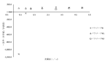
- the inventors calculated the differential pressure ⁇ P with only one parameter set B using the entire data group A and two parameter sets B1 and B2. The cases where the differential pressure ⁇ P was calculated were compared. The result is shown in FIG.
- the coincidence rate between the measured differential pressure ⁇ P and the calculated differential pressure ⁇ P is very low, particularly in the region where the flow rate Q is small. I understand. This is different from the potential flow in which the fluid is dominant in the inertial force flowing through the tube body 4, and in the vicinity of the first and second measurement holes 51 a and 51 b of the columnar member 5, the viscous force is dominant over the inertial force. This is probably due to the boundary layer.
- the flow rate Q is small, the flow R is not substantially separated, and as the flow rate Q increases, a separated flow R ′ is generated.
- the flow rate Q is small as shown in FIG. 7 (results using the parameter B1 are shown in FIG. Also in the region indicated by the symbol ⁇ in the figure, it can be seen that the coincidence ratio between the measured differential pressure ⁇ P and the calculated differential pressure ⁇ P is high. Further, even in a region where the flow rate Q is larger (the result using the parameter B2 is indicated by the symbol ⁇ in the figure), the coincidence rate between the calculated differential pressure ⁇ P and the calculated differential pressure ⁇ P is high. Recognize.
- two parameter sets B including the coefficients c1 to c3 of the flow rate calculation formula are generated based on the reference differential pressure ⁇ P ′, and the parameter set can be selected according to the measured differential pressure.
- the flow rate Q can be accurately calculated from the differential pressure ⁇ P even in a laminar flow region or a transition region where the flow rate Q is small.
- symbol is attached
- the tip 53 of the columnar member 5 is in contact with the tube inner surface 41a (contacts with the tube inner surface 41a or adheres to the tube inner surface 41a).
- the columnar member 5 is not limited to this, and it is not necessary to bring the tip 53 into contact with the pipe inner surface 41a.
- the length L ⁇ b> 2 in the extending direction Y of the columnar member 5 in the tube interior 40 may be smaller than the diameter D of the tube body 4. For example, as shown in FIG. 8, the length may be slightly longer than half (radius) of the diameter D of the tube body 4.
- the pressure received from the fluid of the columnar member 5 ′ is reduced, so that the pressure loss can be reduced and the durability is also improved.
- the first measurement hole 51′a as the first pressure receiving portion is provided on the upstream side US of the columnar member 5, and the second measurement hole 51′b as the second pressure receiving portion is provided on the downstream side DS.
- the differential pressure ⁇ P of the second measurement holes 51′a and 51′b was measured.
- two sets of parameter sets including the coefficients c1 to c3 of the flow rate calculation formula of the above equation 1 are generated on the basis of the reference differential pressure as well as the reference differential pressure. It is also possible to select one of two parameter sets generated by comparing the measured differential pressure of the fluid and the reference differential pressure, and calculate the flow rate.
- the 9 includes a Pitot tube 60 that extends in a direction Z perpendicular to the fluid flow direction X and that does not block the flow path 40.
- the first pressure receiving portion is a first opening 61 a provided in the tube wall 41 of the tube body 4.
- the Pitot tube 60 is located downstream of the first opening 61a in the flow direction X.
- the second pressure receiving portion is a second opening 61 b provided on the downstream side DS of the Pitot tube 60.
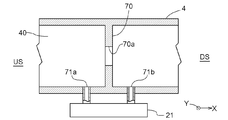
- the tube body 4 is provided with an orifice 70 having a small opening 70a by reducing the conduit on the tube wall 41.
- the first pressure receiving portion is a first opening 71 a provided in the pipe wall 41 on the upstream side US in the fluid flow direction X from the orifice 70.
- the second pressure receiving portion is a second opening 71 b provided in the pipe wall 41 on the downstream side DS in the fluid flow direction X with respect to the orifice 70.
- the straight pipe portion required before and after the flow direction X of the Pitot tube 60 and the orifice 70 becomes long, and the above-described embodiment in which the straight pipe portions before and after the columnar member 5 can be shortened is measured. It is excellent in that the applicable part (range) of the apparatus becomes wide.
- the measuring device 2 and the processing machine 3 are provided with a communication unit, but may be integrated.
- the data processing unit 32, the display unit 33, and the like can be provided in the measuring instrument 2 itself.
- respiration has been described as an example of the fluid.
- the fluid is not limited to breathing, and may be, for example, a medical gas such as oxygen for an inpatient attached to a wall of a hospital room.
- a medical gas such as oxygen for an inpatient attached to a wall of a hospital room.
- the present invention can be applied not only to medical gas but also to other gases and liquids.
- a pipe-shaped member provided in the measuring device may be inserted by making a hole in the pipe, or a pipe provided with the columnar member may be connected by cutting the existing pipe. .
- the present invention can be used as a flow rate measuring apparatus and a flow rate measuring method for measuring flow rates of various gases and liquids as well as a flow rate (respiratory capacity) associated with respiration.
Landscapes
- Physics & Mathematics (AREA)
- Fluid Mechanics (AREA)
- General Physics & Mathematics (AREA)
- Measuring Volume Flow (AREA)
Abstract
乱流領域のみならず層流領域から遷移領域においても精度良く流量を計測することが可能な流量計測装置及び流量計測方法を提供すること 処理機は、既知の流量とこれに対する計測された差圧から下記式1の流量計算式における基準差圧を求め、基準差圧を境に流量計算式の係数c1~c3を含むパラメータセットを2組生成するパラメータ生成部と、計測対象の流体の計測された差圧と基準差圧とを比較して2組のパラメータセットのいずれかを選択する差圧判定部と、パラメータセット及び計測された差圧から流体の流量を算出する流量算出部とを有する。 (式1)ΔP=c1×η×Q+c2×ρ×Q2+c3 (Q:流量、ΔP:差圧、η:動粘度係数、ρ:密度、c1~c3:係数)
Description
本発明は、流量計測装置及び流量計測方法に関する。さらに詳しくは、流体が流れる管体の第一受圧部における第一圧力と前記管体の第二受圧部における第二圧力との差圧を計測する計測器と、計測された差圧から前記流体の流量を算出する処理機とを備える流量計測装置及び流量計測方法に関する。
従来、上述の如き流量計測装置として、例えば、特許文献1に記載の如きものが知られている。この装置は、導通路に設けた静圧測定孔で測定された静圧と後流圧検出管で測定された後流圧の差圧を用いて流体の流量を計測する。流体の流れには、層流領域と乱流領域とその間に層流領域から乱流領域へ変化する遷移領域とが存在する。しかし、この差圧式流量計では、そのような流体の状況を考慮して流量を算出しておらず、更なる計測精度の向上が望まれていた。
かかる従来の実情に鑑みて、本発明は、乱流領域のみならず層流領域から遷移領域においても精度良く流量を計測することが可能な流量計測装置及び流量計測方法を提供することを目的とする。
上記目的を達成するため、本発明に係る流量計測装置の特徴は、流体が流れる管体の第一受圧部における第一圧力と前記管体の第二受圧部における第二圧力との差圧を計測する計測器と、計測された差圧から前記流体の流量を算出する処理機とを備える構成において、前記処理機は、複数の既知の流量と前記複数の既知の流量に対する計測された差圧から下記式1の流量計算式における基準差圧を求めると共に、前記基準差圧を境に前記流量計算式の係数c1~c3を含むパラメータセットを2組生成するパラメータ生成部と、計測対象の流体の計測された差圧と前記基準差圧とを比較して生成された2組のパラメータセットのいずれかを選択する差圧判定部と、選択されたパラメータセット及び前記計測された差圧を前記流量計算式に代入して前記流体の流量を算出する流量算出部とを有することにある。
(式1):ΔP=c1×η×Q+c2×ρ×Q2+c3
(Q:流量、ΔP:差圧、η:動粘度係数、ρ:密度、c1~c3:係数)
(式1):ΔP=c1×η×Q+c2×ρ×Q2+c3
(Q:流量、ΔP:差圧、η:動粘度係数、ρ:密度、c1~c3:係数)
ところで、管体の内部を流れる流体には、滑らかで渦の無い安定した流れとなる粘性力が支配的な層流領域と、様々な渦が発生する慣性力が支配的な乱流領域と、層流領域と乱流領域との間において粘性力と慣性力とが共存する遷移領域とが存在する。この流体の差圧ΔPは、上記式1の流量Qの二次関数で表される流量計算式で求まる。ここで、c1×η×Qを粘性項、c2×ρ×Q2を慣性項と称する。層流領域と乱流領域とは流体の流れの状況が異なり、流量計算式における粘性項及び慣性項への依存は異なる。
上記構成によれば、複数の既知の流量と複数の既知の流量に対する計測された差圧から上記式1の流量計算式における基準差圧を求めると共に、基準差圧を境に上記流量計算式の係数c1~c3を含むパラメータセットを2組生成する。これにより、基準圧力を境に流量計算式を層流剥離がほとんど発生していない範囲(流量が小さい場合)と、層流剥離が発生している範囲(流量が大きい場合)とに相当する範囲に分け、各範囲において流量計算式の係数を生成するので、柱状部材の外周面近傍の流体の流れの状況に応じた係数であるパラメータセットを生成できる。そして、計測対象の流体の計測された差圧と基準差圧とを比較して生成された2組のパラメータセットのいずれかを選択し、選択されたパラメータセット及び計測された差圧を流量計算式に代入して流体の流量を算出するので、測定対象の流体の状況に応じたパラメータに基づいて流量を算出でき、計算精度が向上する。しかも、基準差圧を境に異なるパラメータを生成するので、上述の遷移領域や層流領域が含まれる程度に流量が小さい領域での計算精度も向上する。よって、乱流領域のみならず層流領域から遷移領域においても精度良く流量を計測することが可能となる。
上記構成において、前記管体は、その内部に前記流体の流れ方向に直交する方向に延在する柱状部材を備え、前記第一受圧部は、前記柱状部材の前記流れ方向の上流側に設けた第一測定孔であり、前記第二受圧部は、前記柱状部材の前記流れ方向の下流側に設けた第二測定孔であり、前記柱状部材は、前記管体の中心軸に直交し且つ前記柱状部材の前記流れ方向に沿う長さの中心を通る第一平面に対し線対称となる流線形状を呈し、前記第一測定孔と前記第二測定孔とは前記第一平面に対し対称に配置されているとよい。管体の内部に流体の流れ方向に直交する方向に延在する柱状部材が、流れ方向に沿う長さの中心を通る第一平面に対し線対称となる流線形状を呈するので、この流線形状に沿って流れる流体によって層流や乱流が生じる。そして、柱状部材には、流れ方向の上流側に第一受圧部として第一測定孔と下流側に第二受圧部として第二測定孔とが第一平面に対し線対称に配置されている。これにより、柱状部材は、流体の流れ方向に対して双方向性を有するので、流れ方向に対応してパラメータを設定しなおす必要がない。よって、流体の流れ方向が逆になった場合でも、柱状部材による流体の変化(速度や圧力変化等)の分布も同様に、第一平面に対して対称となるので、流体の流れ方向を問わず、同じパラメータセットを用いて流量を計測することができる。
前記柱状部材は、前記管体の中心軸を含み且つ前記柱状部材の延在方向に平行な第二平面に対し線対称であるとよい。これにより、柱状部材の流体から受ける圧力が第二平面に対し左右で略均一となるので、計測精度が向上すると共に柱状部材の耐久性も向上する。
前記柱状部材は、前記第一平面及び前記第二平面に直交する第三平面上に投影される形状が下記式2及び式3で定義される外周面を有するとよい。
(式2)L=2(K+r)
(式3)d=2(K(1/cosθ-tanθ)+r)
(O:原点、d:柱状部材の幅、L:柱状部材の流れ方向の長さ、r:原点Oから流れ方向に±K離れた点aを中心とした円弧の半径、θ:円弧の中心角/2)
(式2)L=2(K+r)
(式3)d=2(K(1/cosθ-tanθ)+r)
(O:原点、d:柱状部材の幅、L:柱状部材の流れ方向の長さ、r:原点Oから流れ方向に±K離れた点aを中心とした円弧の半径、θ:円弧の中心角/2)
上記式2,3によれば、柱状部材の管径方向の幅dは、円弧の中心角に依存することとなる。柱状部材の流れ方向の長さと円弧の中心角とを調整することで、乱流の発生及び圧力損失を制御でき、測定精度が向上する形状とすることができる。
前記柱状部材の前記管体内部における延在方向の長さは、前記管体の直径よりも小であるとよい。これにより、柱状部材の延在方向の端部と管壁との間に流体が流下可能な隙間が形成され、流体の流れ方向に対する管断面の柱状部材の占める割合が低下する。従って、柱状部材による流体の圧力損失を抑制することができ且つ測定精度も確保できる。
前記第一測定孔及び前記第二測定孔は、前記管体の中心軸上に位置するとよい。これにより、管体を流れる流体による圧力が最も高い中心での差圧を計測するので、流量の計測精度が向上する。
前記柱状部材は中実であり、前記第一測定孔及び前記第二測定孔のそれぞれに計測器へと連通する管状の連通路が形成されていてもよい。中実とすることで、流体に対する強度(抵抗)を確保しつつ、測定精度も確保できる。
上記いずれかに記載の構成において、前記流体は、呼吸であるとよい。上述した如く、柱状部材が双方向性を有するので、本発明に係る流量測定装置は、例えば、呼吸測定装置として実施することができる。また、前記流体は、医療用ガスであってもよい。
前記流体の流れ方向に直交する方向に延在する柱状部材をさらに備え、前記第一受圧部は、前記管体の管壁に設けた第一開口であり、前記柱状部材は、前記第一開口よりも前記流れ方向の下流側に位置し、前記第二受圧部は、前記柱状部材の前記下流側に設けた第二開口であってもよい。
また、前記管体は、管壁に管路を縮小させるオリフィスを備え、前記第一受圧部は、前記オリフィスよりも前記流体の流れ方向の上流側の前記管壁に設けた第一開口であり、前記第二受圧部は、前記オリフィスよりも前記流体の流れ方向の下流側の前記管壁に設けた第二開口であってもよい。
また、上記目的を達成するため、本発明に係る流量計測方法の特徴は、流体が流れる管体の第一受圧部における第一圧力と前記管体の第二受圧部における第二圧力との差圧を計測し、計測した差圧から前記流体の流量を算出する方法において、既知の流量の流体を前記管体に流し、複数の既知の流量と前記複数の既知の流量に対する計測された差圧から下記式4の流量計算式における基準差圧を求めると共に、前記基準差圧を境に前記流量計算式の係数c1~c3を含むパラメータセットを2組生成し、計測対象の流体を前記管体に流し、前記測定対象の流体の計測された差圧と前記基準差圧とを比較して生成された2組のパラメータセットのいずれかを選択し、選択されたパラメータセット及び前記計測された差圧を前記流量計算式に代入して前記流体の流量を算出することにある。
(式4)ΔP=c1×η×Q+c2×ρ×Q2+c3
(Q:流量、ΔP:差圧、η:動粘度係数、ρ:密度、c1~c3:係数)
(式4)ΔP=c1×η×Q+c2×ρ×Q2+c3
(Q:流量、ΔP:差圧、η:動粘度係数、ρ:密度、c1~c3:係数)
上記本発明に係る流量計測装置及び流量計測方法の特徴によれば、乱流領域のみならず層流領域から遷移領域においても精度良く流量を計測することが可能となった。
本発明の他の目的、構成及び効果については、以下の発明の実施の形態の項から明らかになるであろう。
次に、図1~7を参照しながら、本発明をさらに詳しく説明する。
本発明に係る流量計測装置1は、図1に示すように、大略、流体が流れる管体4における差圧ΔPを計測する計測器2と、計測された差圧ΔPから流体の流量Qを計算する処理機3とを備える。なお、本実施形態において、流体は人体の呼吸である。
本発明に係る流量計測装置1は、図1に示すように、大略、流体が流れる管体4における差圧ΔPを計測する計測器2と、計測された差圧ΔPから流体の流量Qを計算する処理機3とを備える。なお、本実施形態において、流体は人体の呼吸である。
計測器2は、図5に示すように、後述する第一受圧部51aにおける第一圧力と第二受圧部51bにおける第二圧力を計測する圧力センサ21と、圧力センサ21で計測された信号をデジタルデータに変換するA/D変換器22と、A/D変換器22で変換したデジタルデータを処理機3の第二通信部31に送信する第一通信部23とを備える。なお、同図の例では、処理機3との通信はBluetooth(登録商標)等の無線通信手段を用いているが、有線にてデータ通信を行っても構わない。
処理機3は、図5に示すように、第一通信部23からのデジタルデータを受信する第二通信部31と、受信したデジタルデータのデータ処理を行うデータ処理部32と、データ処理されたデータ等を表示する表示部33とを備える。なお、処理機3としては、タブレットやスマートフォン等の携帯端末やパーソナルコンピュータ(PC)を用いることができる。
データ処理部32は、図5に示すように、後述する基準差圧ΔP’を求めると共に基準差圧ΔP’を境に流量計算式の係数c1~c3を含むパラメータセットBを2組設定するパラメータ設定部34と、計測対象の流体の計測された差圧ΔPと基準差圧ΔP’とを比較して2組のパラメータセットのいずれかを選択する差圧判定部35と、選択されたパラメータセット及び計測された差圧ΔPを流量計算式に代入して流体の流量Qを算出する流量算出部36とを有する。また、データ処理部32は、受信したデジタルデータ、設定したパラメータや算出した流量Q等を記憶する記憶部37を備える。
管体4は、図1,2に示すように、筐体20を貫通して取り付けられた円管である。この管体4は、その内部40に流体の流れ方向Xに直交する方向Zに延在する柱状部材5を備える。本実施形態において、柱状部材5は、管壁41を貫通すると共に先端53を管内面41aに当接させて管体4に固定される。
本実施形態において、柱状部材5は、図2に示すように、この柱状部材5における流れ方向Xの上流側USに第一受圧部としての第一測定孔51aと、流れ方向Xの下流側DSに第二受圧部としての第二測定孔51bとが設けられている。これら第一、第二測定孔51a,51bは、管体4の中心軸42上に位置させてある。円管内40を流れる流体の圧力は、柱状部材5の上流側USの管軸42付近が最も高くなる。また、下流側DSの管軸42付近では、乱流によって生じる微真空の影響を受けやすい。従って、第一測定孔51a及び第二測定孔51bを管体4の中心軸42上に位置させることで、計測される差圧ΔPが大きくなり、差圧ΔPを用いて算出される流量Qの精度が向上する。
また、柱状部材5に差圧ΔPを計測する第一、第二受圧部51a,51bを設けたので、例えば絞り機構(オリフィス)を備えた従来のオリフィス流量計や上記特許文献1に記載の後背圧型差圧式流量計の如く、静圧を計測する静圧孔を管体4の管壁41に設ける必要がない。そのため、差圧ΔPを測定する受圧部51の前後に必要とされる直管領域を管体4の直径D程度とすることができる(オリフィス流量計では直径Dの15倍程度、後背圧型差圧式流量計では直径Dの4倍程度)。従って、これまでの流量計測装置に比べ非常に小型化・軽量化が可能となり、本実施形態の例では管体4の全長を短くでき、計測器2をコンパクトとすることができる。
さらに、柱状部材5は、図2に示すように、本体部50は中実であり、その内部に第一測定孔51a及び第二測定孔51bのそれぞれに連通する管状の第一、第二連通路52a,52bが形成されている。本体部50を中実とすることで、測定精度を低下されることなく、流体の流れに対する強度を確保できる。また、細い管を製作する場合と比較し、製作も容易であり連通路52自体の強度も確保できる。この第一、第二連通路52a,52bの他端には、圧力センサ21が接続され、差圧ΔPが計測される。
柱状部材5は、図2に示すように、管体4の中心軸42に直交し且つ柱状部材5の流れ方向Xに沿う長さLの中心Oを通る第一平面S1に対し線対称となる流線形状を呈する。また、第一測定孔51a及び第二測定孔51bは第一平面S1に対し線対称に配置されている。これにより、柱状部材5は、流体の流れ方向Xに対し双方向性を有することとなる。従って、本実施形態における流体としての呼吸は、呼気と吸気とで流れ方向Xが反対となるが、装置自体や後述するパラメータセットBを変える必要はない。このように、流体の流れ方向Xを問わず差圧ΔPを計測して流量Qを測定することができる。また、柱状部材5は、管体4の中心軸42を含み柱状部材5の延在方向Zに平行な第二平面S2に対し線対称である。第二平面S2に対して線対称であるので、図3に示すように、柱状部材5及び柱状部材5と管壁41との隙間G1が、流れ方向X視で左右対称となる。よって、柱状部材5にかかる流体による圧力は第二平面S2の両側で略均一となり、柱状部材5の耐久性が向上する。
また、本実施形態に係る流線形状を呈する柱状部材5は、第一平面S1及び第二平面S2に直交する第三平面S3上に投影される形状が上述の式2及び式3にて定義される外周面50aを有する。なお、原点Oは柱状部材5の中心とする。ここで、流線形状とは、第三平面S3上に投影される形状が、流れ方向Xに沿ってなだらかに連続する曲線であることを指す。本実施形態では、図4に示すように、柱状部材5の外周面50aの形状は、上流側USの端部と下流側DSの端部が中心角θ及び半径aで定義される円弧であり、この両端部(円弧部)が流れ方向Xに沿うようになめらかな曲線で接続されている形状である。なお、両端部を接続する曲線は、同図に示す如く、第一平面S1に向かうに従い外方へ膨出し、その第一平面S1との交点が最も膨出している。
ここで、上記式1の流量計算式において、c1×η×Qの項を粘性項、c2×ρ×Q2の項を慣性項と称する。流体の温度及び圧力がほぼ一定の場合、動粘度係数η及び密度ρは流体において一定の値であるので、粘性力と慣性力の大きさは、c1とc2の大きさの関係であるといえる。パラメータ生成部34で生成されるパラメータセットBは、この流量計算式の各項における係数c1,c2,c3の組合せである。
流体は、差圧ΔPの計測時に柱状部材5に衝突して流れを変更される。この時の柱状部材5の形状によって、粘性項及び慣性項のパラメータが変化する。具体的には、円形のように柱状部材5の幅dが大きくなると慣性力が大きくなる。一方、楕円形のように流下方向の柱状部材5の長さLを長くするほど粘性力が大きくなるが、長さLが長すぎると、乱流境界層へと遷移し、渦の過渡特性の影響を受ける。
式1に示す流量計算式の流量Qを変数とする一次の項である粘性項は、柱状部材5の流れ方向Xの長さLに比例するので、流量計算式の傾きNは、N=2×c2×ρ×Q+c1’×η×Lとなる。従って、特に、流量Qが小さい(差圧ΔPが小さい)場合は、N=c1’×η×Lと近似できるので、長さLが流量計算式の傾きNにおいて支配的となる。そのため、長さLを増加させると傾きNが大きくなり、差圧ΔPが小さい場合の流量Qの計算精度が向上する。
また、流量計算式の二次の項である慣性項は、柱状部材5の流れ方向Xの断面積に比例するので、柱状部材5の幅dが減少すると、流量計算式の傾きNにおいて、長さLがより支配的となる。また、柱状部材の幅dを減少させると、流れ方向Xに直交する断面において、柱状部材5が占める面積が小さいため、圧力損失を軽減することができる。
ところで、柱状部材5の外周面50a近傍には、流れ方向Xに沿って流体による境界層が形成される。この境界層は、流体の流量Qが小さい場合は、層流よりなる層流境界層となり、流量Qが大きい場合は、乱流よりなる乱流境界層となる。さらに、層流境界層では、図4に示すように、流量Qが小さい時は外周面50aに沿う流れRとなるが、流量Qが大きくなると外周面50aから剥離する流れR’となる。すなわち、流量Qが大きくなるにつれて、剥離しない層流境界層(流れR)から、剥離する層流境界層(流れR’)、さらに遷移領域を経て、乱流境界層となる。ただし、境界層の状態が変化する流量Qは、柱状部材5の形状によっても異なり、幅dが大きいと層流境界層の流れRが剥離した流れR’と変化しやすく、長さLが長いと流れRから剥離した流れR’に変化しにくい。また、層流境界層で剥離した流れR’が生じた場合、その地点から下流DSの柱状部材5では圧力が低下する(負圧となる)。
次に、本実施形態の流量計測装置1を用いて流体の流量Qを計測する手順を説明する。
まず、既知の異なる流量Qを管体4に流し、流量Qに対応する差圧ΔPを計測器3にて複数回計測し、流量Qに対する差圧ΔPの全データ群Aを取得する。
まず、既知の異なる流量Qを管体4に流し、流量Qに対応する差圧ΔPを計測器3にて複数回計測し、流量Qに対する差圧ΔPの全データ群Aを取得する。
次に、例えば、仮基準流量Q’’及びそれに対する仮基準差圧ΔP’’を決定し、全データ群Aの内、基準流量Q’及び基準差圧ΔP’より小さい範囲に位置するデータを小データ群A1とし、これ以外のデータを大データ群A2とする。そして、図6に示すように、小データ群A1を用いてパラメータセットB1=(c11,c12,c13)を生成し、大データ群A2を用いてパラメータセットB2=(c21,c22,c23)を生成する。さらに、各パラメータセットB1,B2により各データの流量を算出し、実際の流量と比較する。この仮基準流量Q’’及び仮基準差圧ΔP’’を変化させて、実際の流量とパラメータセットB1,B2を用いて算出した流量との一致率が最も高くなる仮基準差圧ΔP’’を基準差圧ΔP’とする。
パラメータセットB1,B2を生成した後、実際の呼吸の測定に際して、被験者は、管体4の第一端部4aから管体4の第二端部4bへ呼気を送り込む。その際、第一,二測定孔51a,51bで呼気の差圧ΔPを圧力センサ21が計測する。計測された差圧ΔPは、第一通信部23及び第二通信部31で送受信され、データ処理部32に入力される。そして、差圧判定部35が、パラメータ生成部34で生成された基準差圧ΔP’と計測された差圧ΔPとの大小関係を比較する。差圧判定部35は、差圧ΔPが基準差圧ΔP’よりも小さい場合はパラメータセットB1を選択し、差圧ΔPが基準差圧ΔP’よりも大きい場合はパラメータセットB2を選択する。
そして、流量算出部35が、選択されたパラメータセットB及び計測された差圧ΔPを流量計算式に代入して流量Qを算出する。算出された流量Qは記憶部37に記憶されると共に、表示部33にて表示される。ここで、流量計測装置1の柱状部材5は双方向性を有するので、呼気のみならず吸気も同様に測定できる。すなわち、1つの流量計測装置1で設定等を変更することなく、呼気及び吸気の双方を計測することができる。なお、表示部33に表示される流量Qは、どのような形態で表示されてもよく、例えば、横軸を時間とし縦軸を流量Qとした時間遷移グラフや、測定開始時からの積算流量として表示されてもよい。
ここで、発明者らは、本願発明の有効性を確かめるべく、全データ群Aを用いて1組のパラメータセットBのみで差圧ΔPを計算した場合と、二つのパラメータセットB1,B2を用いて差圧ΔPを計算した場合を比較した。その結果を図7に示す。
図7に示すように、パラメータセットB(図中の記号×)では、特に、流量Qが小さい領域において、計測された差圧ΔPと計算された差圧ΔPとの一致率が非常に低いことがわかる。これは、流体が、管体4を流れる慣性力が支配的なポテンシャル流れとは異なり、柱状部材5の第一,二測定孔部51a,51b近傍では、慣性力よりも粘性力が支配的な境界層であるためと考えられる。ここで、流量Qが小さい場合、流れRはほぼ剥離しておらず、流量Qが大きくなるにつれて、剥離した流れR’が発生する。この剥離の有無によって、流量計算式において粘性力と慣性力との支配度が大きく変化すると考えられるので、1組のパラメータセットBのみで流体の流れの各状況に応じて精度よく流量を算出するのは限界がある。
一方で、基準差圧ΔP’を境界として、流量計算式に適用するパラメータセットB1,B2を選択可能とした場合は、図7に示すように流量Qが小さい(パラメータB1を用いた結果を図中の記号△で示す)領域においても、計測された差圧ΔPと計算された差圧ΔPとの一致率が高いことがわかる。また、それよりも流量Qが大きい領域(パラメータB2を用いた結果を図中の記号□で示す)においても、計算された差圧ΔPと計算された差圧ΔPとの一致率が高いことがわかる。このように、基準差圧ΔP’により流量計算式の係数c1~c3を含むパラメータセットBを2組生成し、計測された差圧に応じてパラメータセットを選択可能にしたことで、乱流のみならず、流量Qが小さい層流領域や遷移領域においても精度良く差圧ΔPから流量Qを算出することが可能である。
最後に、本発明の他の実施形態の可能性について言及する。なお、上述の実施形態と同様の部材には同一の符号を附してある。
上記実施形態において、柱状部材5の先端53が管内面41aに当接(管内面41aに接触または管内面41aに固着)するようにした。しかし、柱状部材5はこれに限られるものではなく、先端53を管内面41aに当接させる必要はない。柱状部材5の管内部40における延在方向Yの長さL2は、管体4の直径Dよりも小であってもよい。例えば、図8に示すように、管体4の直径Dの半分(半径)より若干長い程度の長さでもよい。先端53’と管内面41aとの間に隙間G2を形成することで、柱状部材5’の流体から受ける圧力が減少するので、圧力損失を減少させることができ、耐久性も向上する。但し、係る場合、第一、二測定孔51a,51bの位置を管体4の軸中心近辺とすることが望ましい。これにより、計測精度の低下も回避できる
上記実施形態において、柱状部材5の先端53が管内面41aに当接(管内面41aに接触または管内面41aに固着)するようにした。しかし、柱状部材5はこれに限られるものではなく、先端53を管内面41aに当接させる必要はない。柱状部材5の管内部40における延在方向Yの長さL2は、管体4の直径Dよりも小であってもよい。例えば、図8に示すように、管体4の直径Dの半分(半径)より若干長い程度の長さでもよい。先端53’と管内面41aとの間に隙間G2を形成することで、柱状部材5’の流体から受ける圧力が減少するので、圧力損失を減少させることができ、耐久性も向上する。但し、係る場合、第一、二測定孔51a,51bの位置を管体4の軸中心近辺とすることが望ましい。これにより、計測精度の低下も回避できる
上記実施形態において、柱状部材5の上流側USに第一受圧部としての第一測定孔51’aを設けると共に下流側DSに第二受圧部としての第二測定孔51’bを設け、第一、第二測定孔51’a,51’bの差圧ΔPを測定した。しかし、図9,10に示す如き流量計においても、基準差圧を求めると共に基準差圧を境に上記式1の流量計算式の係数c1~c3を含むパラメータセットを2組生成し、計測対象の流体の計測された差圧と基準差圧とを比較して生成された2組のパラメータセットのいずれかを選択し、流量を算出することも可能である。
図9に示す流量計の場合、流体の流れ方向Xに直交する方向Zに延在し、流路40を塞がない柱状部材としてのピトー管60を備える。第一受圧部としては、管体4の管壁41に設けた第一開口61aである。ピトー管60は、第一開口61aよりも流れ方向Xの下流側DSに位置する。第二受圧部としては、ピトー管60の下流側DSに設けた第二開口61bである。
また、図10に示す流量計の場合、管体4は、管壁41に管路を縮小させ、小開口70aを有するオリフィス70を備える。第一受圧部としては、オリフィス70よりも流体の流れ方向Xの上流側USの管壁41に設けた第一開口71aである。第二受圧部としては、オリフィス70よりも流体の流れ方向Xの下流側DSの管壁41に設けた第二開口71bである。ただし、図9,10の例では、ピトー管60及びオリフィス70の流れ方向Xの前後に必要となる直管部が長くなり、柱状部材5の前後の直管部を短くできる上記実施形態は計測装置の適用可能箇所(範囲)が広くなる点で優れている。
また、上記実施形態において、計測器2及び処理機3に通信部を設けて別体で構成したが、一体にしても構わない。例えば、計測器2自体にデータ処理部32や表示部33等を設けることも可能である。
上記実施形態において、流体として呼吸を例に説明した。しかし、流体は呼吸に限られるものではなく、例えば、病室の壁に備え付けの入院患者への酸素等の医療用ガスであってもよい。もちろん、医療用ガスに限らず、他の気体や液体にも適用可能である。さらに、既設の管に流れる流量を計測する場合、管に穴を開けて測定器に備わる柱状部材を挿入してもよく、既設の管を切断して柱状部材を備える管を接続してもよい。
本発明は、呼吸に伴う流量(肺活量)のみならず、種々のガスや、液体の流量を計測する流量計測装置及び流量計測方法として利用することができる。
1:流量測定装置、2:計測器、3:処理機、4:管体(円管)、4a:第一端部(導入部)、4b:第二端部(開放部)、5:柱状部材、20:筐体、21:圧力センサ、22:A/D変換器、23:第一通信部(送信部)、31:第二通信部(受信部)、32:データ処理部、33:表示部、34:パラメータ生成部、35:差圧判定部、36:流量算出部、37:記憶部、40:管内部(流路)、41:管壁、41a:管内面、42:中心軸(管軸)、50:本体部、50a:外周面、51:受圧部(測定孔)、51a:第一受圧部(第一測定孔)、51b:第二受圧部(第二測定孔)、52:連通路、52a:第一連通路、52b:第二連通路、60:ピトー管、61a:第一開口、61b:第二開口、70:オリフィス、71a:第一開口、71b:第二開口、A:全データ群、A1:小データ群、A2:大データ群、B:パラメータセット、ΔP:差圧、ΔP’:基準差圧、R:剥離しない流れ、R’:剥離した流れ、X:流れ方向(管軸方向)、Y:直交方向(管径方向)、Z:延在方向、US:上流側、DS:下流側、S1~S3:第一~第三平面
Claims (12)
- 流体が流れる管体の第一受圧部における第一圧力と前記管体の第二受圧部における第二圧力との差圧を計測する計測器と、計測された差圧から前記流体の流量を算出する処理機とを備える流量計測装置であって、
前記処理機は、複数の既知の流量と前記複数の既知の流量に対する計測された差圧から下記式1の流量計算式における基準差圧を求めると共に、前記基準差圧を境に前記流量計算式の係数c1~c3を含むパラメータセットを2組生成するパラメータ生成部と、
計測対象の流体の計測された差圧と前記基準差圧とを比較して生成された2組のパラメータセットのいずれかを選択する差圧判定部と、
選択されたパラメータセット及び前記計測された差圧を前記流量計算式に代入して前記流体の流量を算出する流量算出部とを有する流量計測装置。
(式1)ΔP=c1×η×Q+c2×ρ×Q2+c3
(Q:流量、ΔP:差圧、η:動粘度係数、ρ:密度、c1~c3:係数) - 前記管体は、その内部に前記流体の流れ方向に直交する方向に延在する柱状部材を備え、前記第一受圧部は、前記柱状部材の前記流れ方向の上流側に設けた第一測定孔であり、前記第二受圧部は、前記柱状部材の前記流れ方向の下流側に設けた第二測定孔であり、前記柱状部材は、前記管体の中心軸に直交し且つ前記柱状部材の前記流れ方向に沿う長さの中心を通る第一平面に対し線対称となる流線形状を呈し、前記第一測定孔と前記第二測定孔とは、前記第一平面に対し線対称に配置されている請求項1記載の流量計測装置。
- 前記柱状部材は、前記管体の中心軸を含み且つ前記柱状部材の延在方向に平行な第二平面に対し線対称である請求項1又は2記載の流量計測装置。
- 前記柱状部材は、前記第一平面及び前記第二平面に直交する第三平面上に投影される形状が下記式2及び式3で定義される外周面を有する請求項3記載の流量計測装置。
(式2)L=2(K+r)
(式3)d=2(K(1/cosθ-tanθ)+r)
(O:原点、d:柱状部材の幅、L:柱状部材の流れ方向の長さ、r:原点Oから流れ方向に±K離れた点aを中心した円弧の半径、θ:円弧の中心角/2) - 前記柱状部材の前記管体内部における延在方向の長さは、前記管体の直径よりも小である請求項2~4のいずれかに記載の流量計測装置。
- 前記第一測定孔及び前記第二測定孔は、前記管体の中心軸上に位置する請求項2~5のいずれかに記載の流量計測装置。
- 前記柱状部材は中実であり、前記第一測定孔及び前記第二測定孔のそれぞれに連通する管状の連通路が形成されている請求項2~6のいずれかに記載の流量計測装置。
- 前記流体は、呼吸である請求項1~7のいずれかに記載の流量計測装置。
- 前記流体は、医療用ガスである請求項1~7のいずれかに記載の流量計測装置。
- 前記流体の流れ方向に直交する方向に延在する柱状部材をさらに備え、前記第一受圧部は、前記管体の管壁に設けた第一開口であり、前記柱状部材は、前記第一開口よりも前記流れ方向の下流側に位置し、前記第二受圧部は、前記柱状部材の前記下流側に設けた第二開口である請求項1記載の流量計測装置。
- 前記管体は、管壁に管路を縮小させるオリフィスを備え、前記第一受圧部は、前記オリフィスよりも前記流体の流れ方向の上流側の前記管壁に設けた第一開口であり、前記第二受圧部は、前記オリフィスよりも前記流体の流れ方向の下流側の前記管壁に設けた第二開口である請求項1記載の流量計測装置。
- 流体が流れる管体の第一受圧部における第一圧力と前記管体の第二受圧部における第二圧力との差圧を計測し、計測した差圧から前記流体の流量を算出する流量計測方法であって、
既知の流量の流体を前記管体に流し、
複数の既知の流量と前記複数の既知の流量に対する計測された差圧から下記式4の流量計算式における基準差圧を求めると共に、前記基準差圧を境に前記流量計算式の係数c1~c3を含むパラメータセットを2組生成し、
計測対象の流体を前記管体に流し、
前記測定対象の流体の計測された差圧と前記基準差圧とを比較して生成された2組のパラメータセットのいずれかを選択し、
選択されたパラメータセット及び前記計測された差圧を前記流量計算式に代入して前記流体の流量を算出する流量計測方法。
(式4)ΔP=c1×η×Q+c2×ρ×Q2+c3
(Q:流量、ΔP:差圧、η:動粘度係数、ρ:密度、c1~c3:係数)
Priority Applications (7)
| Application Number | Priority Date | Filing Date | Title |
|---|---|---|---|
| JP2020510314A JP6771254B2 (ja) | 2018-03-28 | 2018-03-28 | 流量計測装置及び流量計測方法 |
| PCT/JP2018/012821 WO2019186783A1 (ja) | 2018-03-28 | 2018-03-28 | 流量計測装置及び流量計測方法 |
| SG11201911606UA SG11201911606UA (en) | 2018-03-28 | 2018-03-28 | Flow rate measurement device and flow rate measurement method |
| US16/615,065 US20200209022A1 (en) | 2018-03-28 | 2018-03-28 | Flow rate measurement device and flow rate measurement method |
| CN202110239048.8A CN113029261A (zh) | 2018-03-28 | 2018-03-28 | 流量计测装置 |
| CN201880032000.6A CN110662946B (zh) | 2018-03-28 | 2018-03-28 | 流量计测装置和流量计测方法 |
| EP18912875.4A EP3779372A4 (en) | 2018-03-28 | 2018-03-28 | FLOW RATE MEASURING DEVICE AND FLOW RATE MEASURING METHOD |
Applications Claiming Priority (1)
| Application Number | Priority Date | Filing Date | Title |
|---|---|---|---|
| PCT/JP2018/012821 WO2019186783A1 (ja) | 2018-03-28 | 2018-03-28 | 流量計測装置及び流量計測方法 |
Publications (1)
| Publication Number | Publication Date |
|---|---|
| WO2019186783A1 true WO2019186783A1 (ja) | 2019-10-03 |
Family
ID=68062573
Family Applications (1)
| Application Number | Title | Priority Date | Filing Date |
|---|---|---|---|
| PCT/JP2018/012821 Ceased WO2019186783A1 (ja) | 2018-03-28 | 2018-03-28 | 流量計測装置及び流量計測方法 |
Country Status (6)
| Country | Link |
|---|---|
| US (1) | US20200209022A1 (ja) |
| EP (1) | EP3779372A4 (ja) |
| JP (1) | JP6771254B2 (ja) |
| CN (2) | CN110662946B (ja) |
| SG (1) | SG11201911606UA (ja) |
| WO (1) | WO2019186783A1 (ja) |
Cited By (1)
| Publication number | Priority date | Publication date | Assignee | Title |
|---|---|---|---|---|
| WO2021201631A1 (ko) * | 2020-04-01 | 2021-10-07 | 주식회사 대한인스트루먼트 | 차압식 유량계 시스템 |
Families Citing this family (5)
| Publication number | Priority date | Publication date | Assignee | Title |
|---|---|---|---|---|
| DE102020129074A1 (de) * | 2020-11-04 | 2022-05-05 | Krohne Messtechnik Gmbh | Durchflussmessgerät, Verfahren zum Betreiben eines Durchflussmessgeräts, Anlage und Verfahren zum Betreiben einer Anlage |
| CN113654944A (zh) * | 2021-07-19 | 2021-11-16 | 中国烟草总公司郑州烟草研究院 | 核查标准恒流孔的方法 |
| CN114152445A (zh) * | 2021-10-20 | 2022-03-08 | 中国航发四川燃气涡轮研究院 | 一种高空台流量管总压径向测点布置方法及测量耙 |
| CN114111930A (zh) * | 2021-12-29 | 2022-03-01 | 觉隆传感技术(深圳)有限公司 | 一种天然气超声波质量流量计 |
| US20240068851A1 (en) * | 2022-08-24 | 2024-02-29 | Electronics And Telecommunications Research Institute | Method, apparatus, and parameter training method for friction loss-based differential pressure flow rate measurement |
Citations (5)
| Publication number | Priority date | Publication date | Assignee | Title |
|---|---|---|---|---|
| JP2005147682A (ja) * | 2003-11-11 | 2005-06-09 | Shimadzu Corp | 流量計及び流量計測法 |
| JP2010101738A (ja) * | 2008-10-23 | 2010-05-06 | Yazaki Corp | 流動状態判別方法 |
| US20100191481A1 (en) * | 2006-08-29 | 2010-07-29 | Richard Steven | Flow metering |
| JP2013134180A (ja) * | 2011-12-27 | 2013-07-08 | Cosmo Instruments Co Ltd | 流量計測方法及びそれを使った流量計測装置 |
| JP3200638U (ja) | 2015-08-14 | 2015-10-29 | 日本アプライドフロー株式会社 | 流量計測装置 |
Family Cites Families (14)
| Publication number | Priority date | Publication date | Assignee | Title |
|---|---|---|---|---|
| US4957007A (en) * | 1988-04-28 | 1990-09-18 | Westinghouse Electric Corp. | Bi-directional pressure sensing probe |
| CN1025756C (zh) * | 1991-06-08 | 1994-08-24 | 冶金部安全环保研究院 | 工业管道气体流量测定装置 |
| EP1041367A4 (en) * | 1997-12-15 | 2005-08-17 | Tokyo Gas Co Ltd | FLOWMETERS |
| JP3648724B2 (ja) * | 1999-07-22 | 2005-05-18 | 東京瓦斯株式会社 | ガスメータおよび流量計 |
| JP3655569B2 (ja) * | 2001-09-06 | 2005-06-02 | 大陽日酸株式会社 | ガス成分濃度測定方法及び装置 |
| CN1668243A (zh) * | 2002-07-24 | 2005-09-14 | 弗萨米德医疗系统有限公司 | 呼吸流量传感器 |
| WO2006020870A1 (en) * | 2004-08-13 | 2006-02-23 | Entegris, Inc. | System and method for calibration of a flow device |
| CN1332183C (zh) * | 2005-08-10 | 2007-08-15 | 陈宇 | 流体的流量检测装置 |
| CN202204541U (zh) * | 2011-07-25 | 2012-04-25 | 明笛 | 双翼型流量传感器 |
| CN104457862B (zh) * | 2014-11-28 | 2018-11-30 | 力合科技(湖南)股份有限公司 | 一种差压式流量计 |
| DE102014119548A1 (de) * | 2014-12-23 | 2016-06-23 | Endress + Hauser Gmbh + Co. Kg | MEMS-Sensor |
| CN204439142U (zh) * | 2015-03-18 | 2015-07-01 | 内蒙古天庆工程机械设备有限公司 | 低流速、高精度皮托管差压式流量传感器取压头 |
| CN107687876A (zh) * | 2016-08-06 | 2018-02-13 | 赵乐 | 一种测量流体流量的测量装置及测量方法 |
| CN107806912A (zh) * | 2017-12-13 | 2018-03-16 | 南京亿准纳自动化控制技术有限公司 | 双向流量测量装置 |
-
2018
- 2018-03-28 WO PCT/JP2018/012821 patent/WO2019186783A1/ja not_active Ceased
- 2018-03-28 EP EP18912875.4A patent/EP3779372A4/en not_active Withdrawn
- 2018-03-28 CN CN201880032000.6A patent/CN110662946B/zh active Active
- 2018-03-28 SG SG11201911606UA patent/SG11201911606UA/en unknown
- 2018-03-28 JP JP2020510314A patent/JP6771254B2/ja active Active
- 2018-03-28 US US16/615,065 patent/US20200209022A1/en not_active Abandoned
- 2018-03-28 CN CN202110239048.8A patent/CN113029261A/zh not_active Withdrawn
Patent Citations (5)
| Publication number | Priority date | Publication date | Assignee | Title |
|---|---|---|---|---|
| JP2005147682A (ja) * | 2003-11-11 | 2005-06-09 | Shimadzu Corp | 流量計及び流量計測法 |
| US20100191481A1 (en) * | 2006-08-29 | 2010-07-29 | Richard Steven | Flow metering |
| JP2010101738A (ja) * | 2008-10-23 | 2010-05-06 | Yazaki Corp | 流動状態判別方法 |
| JP2013134180A (ja) * | 2011-12-27 | 2013-07-08 | Cosmo Instruments Co Ltd | 流量計測方法及びそれを使った流量計測装置 |
| JP3200638U (ja) | 2015-08-14 | 2015-10-29 | 日本アプライドフロー株式会社 | 流量計測装置 |
Non-Patent Citations (1)
| Title |
|---|
| See also references of EP3779372A4 |
Cited By (1)
| Publication number | Priority date | Publication date | Assignee | Title |
|---|---|---|---|---|
| WO2021201631A1 (ko) * | 2020-04-01 | 2021-10-07 | 주식회사 대한인스트루먼트 | 차압식 유량계 시스템 |
Also Published As
| Publication number | Publication date |
|---|---|
| CN110662946B (zh) | 2021-02-23 |
| EP3779372A4 (en) | 2021-03-31 |
| EP3779372A1 (en) | 2021-02-17 |
| JPWO2019186783A1 (ja) | 2020-09-17 |
| CN110662946A (zh) | 2020-01-07 |
| CN113029261A (zh) | 2021-06-25 |
| US20200209022A1 (en) | 2020-07-02 |
| JP6771254B2 (ja) | 2020-10-21 |
| SG11201911606UA (en) | 2020-01-30 |
Similar Documents
| Publication | Publication Date | Title |
|---|---|---|
| JP6771254B2 (ja) | 流量計測装置及び流量計測方法 | |
| US9713438B2 (en) | Flow sensor | |
| JP2980979B2 (ja) | 可変流過妨害面積ガス流量計 | |
| US5979247A (en) | Flow sensor having a fixed resistance and a variable resistance | |
| JP3595337B2 (ja) | 流量測定装置 | |
| US4961344A (en) | Multiple tube flowmeter | |
| Meriläinen et al. | A novel sensor for routine continuous spirometry of intubated patients | |
| US9157774B2 (en) | Differential pressure flow sensor | |
| WO2021218133A1 (zh) | 一种双向双压差式呼吸流量检测传感装置及方法 | |
| WO2009064837A1 (en) | Venturi flow sensor | |
| CN102269604B (zh) | 气体流量计及用于其中的节流装置、呼吸机、麻醉机 | |
| US20090064794A1 (en) | Flow sensor with double obstruction | |
| CN108577845A (zh) | 节流件、差压式肺功能参数监测装置及流量确定方法 | |
| KR101703971B1 (ko) | 휴대용 양방향 호흡량 측정장치 및 방법 | |
| US7574908B2 (en) | Flow rate measuring device | |
| JP6886675B2 (ja) | 流量計測装置 | |
| US20040261540A1 (en) | Method to linearly measure gas volume flow in ducts and flow sensor | |
| US20090211371A1 (en) | Flow measuring device | |
| CA3034374A1 (en) | Device for measuring respiratory parameters of a patient | |
| JP3179720U (ja) | 流量計測装置 | |
| RU73600U1 (ru) | Спирометр | |
| JP3200638U (ja) | 流量計測装置 | |
| US20130345590A1 (en) | Apparatus for quantifying expiratory and inspiratory airflow | |
| CN113040747A (zh) | 肺功能监测评估设备及方法 | |
| KR100682026B1 (ko) | 소형 단방향 기류 계측용 호흡관 |
Legal Events
| Date | Code | Title | Description |
|---|---|---|---|
| 121 | Ep: the epo has been informed by wipo that ep was designated in this application |
Ref document number: 18912875 Country of ref document: EP Kind code of ref document: A1 |
|
| ENP | Entry into the national phase |
Ref document number: 2020510314 Country of ref document: JP Kind code of ref document: A |
|
| NENP | Non-entry into the national phase |
Ref country code: DE |
|
| ENP | Entry into the national phase |
Ref document number: 2018912875 Country of ref document: EP Effective date: 20201028 |