WO2019186957A1 - ユーザ装置及び基地局装置 - Google Patents
ユーザ装置及び基地局装置 Download PDFInfo
- Publication number
- WO2019186957A1 WO2019186957A1 PCT/JP2018/013440 JP2018013440W WO2019186957A1 WO 2019186957 A1 WO2019186957 A1 WO 2019186957A1 JP 2018013440 W JP2018013440 W JP 2018013440W WO 2019186957 A1 WO2019186957 A1 WO 2019186957A1
- Authority
- WO
- WIPO (PCT)
- Prior art keywords
- transmission mode
- transmission
- communication
- base station
- station apparatus
- Prior art date
- Legal status (The legal status is an assumption and is not a legal conclusion. Google has not performed a legal analysis and makes no representation as to the accuracy of the status listed.)
- Ceased
Links
Images


Classifications
-
- H—ELECTRICITY
- H04—ELECTRIC COMMUNICATION TECHNIQUE
- H04L—TRANSMISSION OF DIGITAL INFORMATION, e.g. TELEGRAPHIC COMMUNICATION
- H04L5/00—Arrangements affording multiple use of the transmission path
- H04L5/003—Arrangements for allocating sub-channels of the transmission path
- H04L5/0053—Allocation of signalling, i.e. of overhead other than pilot signals
-
- H—ELECTRICITY
- H04—ELECTRIC COMMUNICATION TECHNIQUE
- H04W—WIRELESS COMMUNICATION NETWORKS
- H04W28/00—Network traffic management; Network resource management
- H04W28/16—Central resource management; Negotiation of resources or communication parameters, e.g. negotiating bandwidth or QoS [Quality of Service]
- H04W28/18—Negotiating wireless communication parameters
-
- H—ELECTRICITY
- H04—ELECTRIC COMMUNICATION TECHNIQUE
- H04L—TRANSMISSION OF DIGITAL INFORMATION, e.g. TELEGRAPHIC COMMUNICATION
- H04L5/00—Arrangements affording multiple use of the transmission path
- H04L5/003—Arrangements for allocating sub-channels of the transmission path
- H04L5/0048—Allocation of pilot signals, i.e. of signals known to the receiver
-
- H—ELECTRICITY
- H04—ELECTRIC COMMUNICATION TECHNIQUE
- H04L—TRANSMISSION OF DIGITAL INFORMATION, e.g. TELEGRAPHIC COMMUNICATION
- H04L5/00—Arrangements affording multiple use of the transmission path
- H04L5/003—Arrangements for allocating sub-channels of the transmission path
- H04L5/0053—Allocation of signalling, i.e. of overhead other than pilot signals
- H04L5/0055—Physical resource allocation for ACK/NACK
Definitions
- the present invention relates to a user apparatus and a base station apparatus in a wireless communication system.
- 5G or NR New Radio
- 5G or NR New Radio
- 5G various wireless technologies are being studied in order to satisfy the requirement to achieve a delay of 1 ms or less while achieving a throughput of 10 Gbps or more.
- Non-Patent Document 1 Ultra Reliable and Low Latency Communications
- 99.999% reliability packet arrival rate, etc.
- 5G needs to flexibly cope with requirements different from high speed and large capacity such as eMBB (enhancedenMobile Broadband).
- the present invention has been made in view of the above points, and an object thereof is to perform communication in response to a request using a transmission mode associated with a plurality of communication capabilities or conditions.
- a control unit that determines one transmission mode to be applied to communication from a plurality of predefined transmission modes based on a plurality of conditions required for communication, and the transmission mode as a base station
- a user apparatus includes a transmission unit that notifies a device and a reception unit that receives a downlink signal to which a transmission parameter associated with the transmission mode is applied from the base station device.
- LTE Long Term Evolution
- LTE-Advanced and LTE-Advanced and subsequent systems eg, NR or 5G.
- SS Synchronization ⁇ Signal
- PSS Primary SS
- SSS Secondary SS
- PBCH Physical broadcast channel
- PRACH Physical
- RACH Radio Access
- the Duplex method may be a TDD (Time Division Division Duplex) method, an FDD (Frequency Division Duplex) method, or other (for example, Flexible Duplex).
- This method may be used.
- transmitting a signal using a transmission beam may be transmitting a signal multiplied by a precoding vector (precoded with a precoding vector).
- receiving a signal using a receive beam may be multiplying the received signal by a predetermined weight vector.
- transmitting a signal using a transmission beam may be transmitting a signal at a specific antenna port.
- receiving a signal using a receive beam may be receiving a signal at a particular antenna port.
- An antenna port refers to a logical antenna port or a physical antenna port defined in the 3GPP standard.
- the method of forming the transmission beam and the reception beam is not limited to the above method.
- a method of changing the angle of each antenna may be used, or a method of combining a method of using a precoding vector and a method of changing the angle of an antenna is used.
- different antenna panels may be switched and used, or a method of combining a plurality of antenna panels may be used, or other methods may be used.
- a plurality of different transmission beams may be used in the high frequency band. The use of multiple transmission beams is called multi-beam operation, and the use of one transmission beam is called single beam operation.
- “to be set” of a radio parameter or the like may be that a predetermined value is set in advance (Pre-configure), or the base station apparatus 100 or the user apparatus The radio parameter notified from 200 may be set.
- FIG. 1 is a diagram for explaining a communication system according to an embodiment of the present invention.
- wireless communications system in embodiment of this invention contains the base station apparatus 100 and the user apparatus 200 as FIG. 1 shows. Although one base station apparatus 100 and one user apparatus 200 are shown in FIG. 1, this is an example, and there may be a plurality of each.
- the base station apparatus 100 is a communication apparatus that provides one or more cells and performs wireless communication with the user apparatus 200.
- the base station apparatus 100 transmits a synchronization signal and system information to the user apparatus 200.
- the synchronization signal is, for example, NR-PSS and NR-SSS.
- the system information is transmitted via, for example, NR-PBCH and is also referred to as broadcast information.
- the base station apparatus 100 transmits application data to the user apparatus 200 via an NR-PDSCH (Physical / downlink / shared channel) scheduled by NR-PDCCH (Physical / downlink / control / channel). Both the base station apparatus 100 and the user apparatus 200 can transmit and receive signals by performing beamforming.
- NR-PDSCH Physical / downlink / shared channel
- NR-PDCCH Physical / downlink / control / channel
- the user device 200 is a communication device having a wireless communication function such as a smartphone, a mobile phone, a tablet, a wearable terminal, or a communication module for M2M (Machine-to-Machine).
- the user apparatus 200 is wirelessly connected to the base station apparatus 100 and uses various communication services provided by the wireless communication system.
- eMBB is not a communication in which quality guarantee or delay amount is guaranteed.
- URLLC introduced in 5G guarantees a packet success rate (arrival rate) and a delay amount. For example, a packet success rate of 99.999% and a wireless section one-way delay within 1 ms are guaranteed.
- URLLC or eMBB it is necessary to design a radio interface that can guarantee a packet arrival rate or a delay amount for a certain packet size or reception quality.
- Radio quality for example, SIR (Signal to interference ratio)
- SIR Signal to interference ratio
- Packet size When the packet size is larger than the transport block size, the packet is divided into a plurality of transport blocks and transmitted, so that the delay increases.
- a plurality of guaranteed transmission modes are defined.
- the transmission mode to be used is determined based on the required communication capability or conditions as described below.
- Packet size or packet size range for example, 32 bytes to 100 bytes, 100 bytes to 500 bytes, etc.
- the packet size may be the transport block size.
- the user apparatus 200 transmits a transmission mode used for downlink communication to the base station apparatus 100.
- the transmission mode is associated with a communication capability or condition that the transmission mode is required, that is, a condition of the transmission mode, and a transmission parameter used in the transmission mode.
- Base station apparatus 100 starts communication in the received transmission mode.
- the number of transmission mode conditions corresponding to a certain transmission mode may be one or more, and the number of transmission parameters corresponding to a certain transmission mode may be one or more.
- the base station apparatus 100 may determine a transmission mode to be applied to downlink communication from a plurality of transmission modes based on the transmission mode condition, and notify the user apparatus 200 of the transmission mode. Moreover, the base station apparatus 100 may determine the transmission mode applied to uplink communication from several transmission modes based on the conditions of transmission mode, and may notify it to the user apparatus 200. Further, the user apparatus 200 may determine a transmission mode to be applied to uplink communication from a plurality of transmission modes based on the transmission mode condition, and notify the base station apparatus 100 of the transmission mode. Moreover, both the transmission mode applied to downlink communication and the transmission mode applied to uplink communication may be determined and applied.
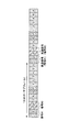
- FIG. 2 is a sequence diagram for explaining an example of a communication procedure in the embodiment of the present invention.
- the user apparatus 200 determines the transmission mode so as to satisfy the application requirements.
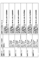
- FIG. 3 is a diagram showing a setting example of the transmission mode in the embodiment of the present invention. As shown in FIG. 3, “transmission mode”, “transmission mode condition”, and “transmission mode parameter” are defined in association with each other. The user apparatus 200 determines which “transmission mode” to use in accordance with the “transmission mode condition” required by the application.
- Transmission mode condition includes “Size”, “Rate”, “Delay” or “CQI (Channel Quality Indicator)”.
- the “transmission mode condition” associated with a certain “transmission mode” is any one, two, or three, or four of the “transmission mode conditions” shown in FIG. Any combination of transmission mode conditions may be used.
- Size indicates the packet size or packet size range used by the application. For example, 32 bytes to 100 bytes, 100 bytes to 500 bytes, and the like. Note that “Size” may be a transport block size.
- Rate indicates a required error rate.
- the error rate may be BLER, Packet error rate (packet error rate), or Packet success probability (packet success rate or packet arrival rate).
- Delay indicates an allowable maximum delay amount.
- the delay may be a radio interval delay, a user plane delay, a one-way delay, or an end-to-end delay.
- CQI is an index indicating the reception quality of the reference signal or an index indicating the reception quality of the data.
- the index indicating the reception quality may be, for example, RSRP (Reference Signal Signal Received Power), RSSI (Received Signal Strength Strength Indicator), RSRQ (Reference Signal Signal Received Quality), SINR (Signal Signal To Interference Value Plus Noise Value), or a CQI index.
- RSRP Reference Signal Signal Received Power
- RSSI Receiveived Signal Strength Strength Indicator
- RSRQ Reference Signal Signal Received Quality
- SINR Signal To Interference Value Plus Noise Value
- the CQI index is an index that specifies a combination of a modulation scheme and a coding rate that achieves a predetermined error rate.
- Transmission mode parameters include “Numerology”, “MCS selection range”, “number of retransmissions, retransmission method” or “MIMO (Multiple Input and Multiple Output) transmission mode”.
- the transmission parameters associated with a certain “transmission mode” can be any one of the transmission parameters shown in FIG. 3, or any two, or any three, or all four. It may be a combination of various transmission parameters.
- a “transmission mode parameter” corresponding to the transmission mode is used for communication.
- “Numerology” is information specifying a radio frame structure.
- Information specifying the radio frame structure includes, for example, information indicating a symbol length, a slot length, the number of symbols per slot, a subcarrier interval, and the like.
- an index indicating “Numerology” may be used to specify a radio frame structure corresponding to each index.
- MCS selection range is information for designating MCS (Modulation and Coding Scheme) used for communication.
- the designated MCS may be a certain fixed MCS or a plurality of MCSs by using a specific MCS table.
- an index indicating “MCS selection range” may be used to specify an MCS corresponding to each index.
- “Retransmission count, retransmission method” is information for specifying an operation related to retransmission.
- the information designating the operation related to retransmission may include information indicating whether or not there is retransmission, n times of retransmission, and the like. Also, the information designating the operation related to retransmission may include information designating whether or not to repeatedly perform transmission, whether to perform retransmission by ACK / NACK in HARQ, and the timing or interval of retransmission. .
- MIMO transmission mode is information indicating a transmission method used for MIMO such as SFBC (Space-frequency block coded), STBC (Space-time block coded), and closed-loop MIMO.
- an index indicating “MIMO transmission mode” may be used to specify a transmission scheme used for MIMO corresponding to each index.
- the user apparatus 200 may determine the “transmission mode” and notify the base station apparatus 100, or the base station apparatus 100 may determine the “transmission mode” and notify the user apparatus 200. Also good.
- the symbol length may be shortened with “Numerology” being a wider subcarrier interval.
- the user plane delay is a time until the packet transmission is successful, the user plane delay per packet increases when it is necessary to retransmit. Therefore, ACK / NACK-less retransmission that does not use ACK or NACK may be used as the retransmission method.
- ACK / NACK-less retransmission the transmission side continuously transmits the same packet or transport block, and if the reception side cannot decode the packet or transport block transmitted first, it continuously transmits. The generated packet or transport block is synthesized and decoded.
- the ACK / NACKless retransmission can realize a lower delay than the ACK / NACK retransmission.
- redundancy is high.
- a non-guaranteed transmission mode which is a conventional best effort type communication, may be defined as one transmission mode so that it can be used.
- the number of retransmissions and the retransmission interval are determined according to the error rate condition or delay condition specified by “transmission mode condition”. For example, if the error rate conditions are severe, the number of retransmissions is increased. For example, when delay conditions are severe, the number of retransmissions is reduced and the retransmission interval is shortened.
- the reception side can recognize the number of retransmissions or the retransmission interval used for communication to which URLLC is applied, and can perform correct communication. If the receiving side does not know the timing for receiving the retransmission signal, the receiving side cannot receive the retransmission signal correctly.
- an index indicating the number of retransmissions and a retransmission interval may be used for notification of “transmission mode parameters” of operations related to retransmission.
- the receiving side uses a predefined table indicating the number of retransmissions and the retransmission interval corresponding to the notified index.
- the “transmission mode parameter” related to the “MCS selection range” it is possible to secure stable communication by limiting the selectable MCS range for each transmission mode. For example, when the packet size is large, if a low MCS is used, packet division occurs and delay increases. Therefore, when the packet size is large, a high MCS is used, and when the packet size is small, a low MCS is used. It may be.
- transmission mode parameters for “transmission mode parameters” related to “MIMO transmission mode”, for example, when it is desired to improve the packet arrival rate, transmission diversity is used. For example, when it is desired to improve the communication speed, communication is performed by MIMO multiplex transmission using a plurality of layers. By switching the “MIMO transmission mode” according to the selected transmission mode, it is possible to guarantee the communication speed and the delay amount while ensuring the communication quality.
- transmission mode 0 when there is no communication capability or condition to be particularly guaranteed as a condition of the transmission mode, “transmission mode 0” is selected.
- Transmission parameters associated with “transmission mode 0” are “Numerology 1”, “MCS selection range 1”, “number of retransmissions, retransmission scheme”, or “MIMO transmission mode 3”.
- MIMO transmission mode 3 may indicate performing transmission diversity, for example.
- Transmission parameters associated with “transmission mode 1” are “Numerology 1”, “MCS selection range 1”, “number of retransmissions, retransmission method”, or “MIMO transmission mode 3”.
- Transmission parameters associated with “transmission mode 2” are “Numerology 1”, “MCS selection range 2”, “number of retransmissions, retransmission method”, or “MIMO transmission mode 8”.
- MIMO transmission mode 8 may indicate, for example, transmission by a plurality of layers.
- Transmission parameters associated with “transmission mode 3” are “Numerology 2”, “MCS selection range 3”, “number of retransmissions, retransmission scheme”, or “MIMO transmission mode 3”.
- Transmission parameters associated with “transmission mode 4” are “Numerology 4”, “MCS selection range 4”, “number of retransmissions, retransmission scheme”, or “MIMO transmission mode 8”.
- Transmission parameters associated with “transmission mode 5” are “Numerology 4”, “MCS selection range 4”, “number of retransmissions, retransmission scheme”, or “MIMO transmission mode 4”.
- MIMO transmission mode 4 may indicate that closed-loop MIMO transmission is performed, for example.
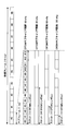
- FIG. 4 is a diagram showing an example of a time-domain radio frame according to the embodiment of the present invention.
- 10 1 ms subframes are arranged in a 10 ms radio frame in NR.
- a slot is composed of 14 OFDM symbols.
- the OFDM subcarrier interval is 15 kHz, one slot can be arranged in one subframe.
- the OFDM subcarrier interval is 30 kHz, two slots can be arranged in one subframe.
- the OFDM subcarrier interval is 60 kHz
- 4 slots can be arranged in one subframe.
- 8 slots can be arranged in one subframe.
- FIG. 5A is a diagram showing an example (1) of retransmission processing according to the embodiment of the present invention.
- FIG. 5B is a diagram illustrating an example (2) of the retransmission processing according to the embodiment of the present invention.
- 5A and 5B show an example in which signals are arranged in two slots in the case where repeated transmission is performed as retransmission processing in the radio frame shown in FIG.
- FIG. 5A is an example in which retransmission signals are arranged in consecutive symbols.
- FIG. 5A is a TDD radio frame, in which 6 symbols of DL (Downlink) signal are arranged from the head in one slot, then 2 symbols of GP (Guard Period) are arranged, and then UL (Uplink) signal 6 symbols are arranged.
- signal # 1 is transmitted by symbol # 1 and symbol # 2 in one slot, and a retransmission signal of signal # 1 is transmitted by symbol # 3 and symbol # 4.
- Signal # 2 is transmitted by symbol # 1 and symbol # 2 in the next one slot, and a retransmission signal of signal # 2 is transmitted by symbol # 3 and symbol # 4.
- a retransmission signal is transmitted using consecutive symbols.
- FIG. 5B is an example in which retransmission signals are arranged in different slots.
- FIG. 5B shows a TDD radio frame, in which 6 symbols of DL signal are arranged from the head in one slot, 2 symbols of GP are arranged next, and 6 symbols of UL signal are arranged next.
- signal # 1 is transmitted using symbol # 1 and symbol # 2 in one slot
- signal # 2 is transmitted using symbol # 3 and symbol # 4.
- the retransmission signal of signal # 1 is transmitted by symbol # 1 and symbol # 2 in the next one slot
- the retransmission signal of signal # 2 is transmitted by symbol # 3 and symbol # 4.
- the delay increases by one slot length, but for example, the delay increase is smaller than the retransmission delay due to ACK / NACK. Can be satisfied.
- step S2 the user apparatus 200 notifies the base station apparatus 100 of the transmission mode determined in step S1 as described above.
- Base station apparatus 100 identifies a transmission parameter used for communication based on the notified transmission mode.
- step S3 the base station apparatus 100 and the user apparatus 200 start communication using the transmission parameter associated with the transmission mode notified in step S2.
- the user apparatus 200 determines the transmission mode according to the communication condition requested by the application, and notifies the base station apparatus 100 of the transmission mode. Using the transmission parameter associated with the notified transmission mode, the base station apparatus 100 and the user apparatus 200 can perform communication.
- communication according to a request can be performed using a transmission mode associated with a plurality of communication capabilities or conditions.
- the base station apparatus 100 and the user apparatus 200 include functions for implementing the above-described embodiments. However, each of the base station apparatus 100 and the user apparatus 200 may have only some functions in the embodiments.
- FIG. 6 is a diagram illustrating an example of a functional configuration of the base station apparatus 100.
- the base station apparatus 100 includes a transmission unit 110, a reception unit 120, a setting information management unit 130, and a transmission mode processing unit 140.
- the functional configuration shown in FIG. 6 is merely an example. As long as the operation
- the transmission unit 110 includes a function of generating a signal to be transmitted to the user apparatus 200 and transmitting the signal wirelessly.
- the reception unit 120 includes a function of receiving various signals transmitted from the user apparatus 200 and acquiring, for example, higher layer information from the received signals. Further, the transmission unit 110 has a function of transmitting NR-PSS, NR-SSS, NR-PBCH, DL / UL control signals, and the like to the user apparatus 200.
- the receiving unit 120 has a function of receiving information specifying the transmission mode from the user device 200.
- the setting information management unit 130 stores setting information set in advance and various setting information to be transmitted to the user apparatus 200.
- the contents of the setting information are, for example, information related to transmission mode parameters.
- the transmission mode processing unit 140 determines the radio frame configuration, the number of repeated transmissions, the retransmission scheme, the MCS or the MIMO transmission mode based on the transmission mode notified from the user apparatus 200, and the parameter. Has a function of starting communication using. Note that the transmission mode determined by the base station apparatus 100 may be used.
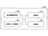
- FIG. 7 is a diagram illustrating an example of a functional configuration of the user device 200.
- the user device 200 includes a transmission unit 210, a reception unit 220, a setting information management unit 230, and a transmission mode control unit 240.
- the functional configuration shown in FIG. 7 is merely an example. As long as the operation
- the transmission unit 210 creates a transmission signal from the transmission data and transmits the transmission signal wirelessly.
- the receiving unit 220 wirelessly receives various signals and acquires higher layer signals from the received physical layer signals.
- the receiving unit 220 has a function of receiving NR-PSS, NR-SSS, NR-PBCH, DL / UL control signals and the like transmitted from the base station apparatus 100.
- the transmission unit 210 has a function of transmitting information specifying a transmission mode to the base station apparatus 100.
- the setting information management unit 230 stores various setting information received from the base station apparatus 100 or the user apparatus 200 by the receiving unit 220.
- the setting information management unit 230 also stores setting information set in advance.
- the contents of the setting information are, for example, information related to transmission mode parameters.
- the transmission mode control unit 240 has a function of determining a radio frame configuration, the number of repeated transmissions, a retransmission method, an MCS or a MIMO transmission mode, and starting communication using the parameters. Note that the transmission mode transmitted from base station apparatus 100 may be used.
- a function unit related to signal transmission in the transmission mode control unit 240 may be included in the transmission unit 210, and a function unit related to signal reception in the transmission mode control unit 240 may be included in the reception unit 220.
- each functional block may be realized by one device in which a plurality of elements are physically and / or logically combined, or two or more devices physically and / or logically separated may be directly and directly. It may be realized by a plurality of these devices connected indirectly (for example, wired and / or wirelessly).
- both the base station apparatus 100 and the user apparatus 200 according to the embodiment of the present invention may function as a computer that performs processing according to the embodiment of the present invention.
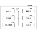
- FIG. 8 is a diagram illustrating an example of a hardware configuration of a radio communication apparatus that is the base station apparatus 100 or the user apparatus 200 according to the embodiment of the present invention.
- Each of the base station apparatus 100 and the user apparatus 200 described above is physically a computer apparatus including a processor 1001, a storage apparatus 1002, an auxiliary storage apparatus 1003, a communication apparatus 1004, an input apparatus 1005, an output apparatus 1006, a bus 1007, and the like. It may be configured.
- the term “apparatus” can be read as a circuit, a device, a unit, or the like.
- the hardware configuration of the base station apparatus 100 and the user apparatus 200 may be configured to include one or a plurality of apparatuses indicated by 1001 to 1006 shown in the figure, or may be configured not to include some apparatuses. May be.
- Each function in the base station apparatus 100 and the user apparatus 200 is performed by causing the processor 1001 to perform computation by reading predetermined software (program) on hardware such as the processor 1001 and the storage device 1002, and the communication by the communication apparatus 1004. This is realized by controlling reading and / or writing of data in the storage device 1002 and the auxiliary storage device 1003.
- the processor 1001 controls the entire computer by operating an operating system, for example.
- the processor 1001 may be configured by a central processing unit (CPU) including an interface with peripheral devices, a control device, an arithmetic device, a register, and the like.
- CPU central processing unit
- the processor 1001 reads a program (program code), software module, or data from the auxiliary storage device 1003 and / or the communication device 1004 to the storage device 1002, and executes various processes according to these.
- a program program that causes a computer to execute at least a part of the operations described in the above embodiments is used.
- the transmission unit 110, the reception unit 120, the setting information management unit 130, and the transmission mode processing unit 140 of the base station apparatus 100 illustrated in FIG. 6 are realized by a control program stored in the storage device 1002 and operating on the processor 1001. May be.
- the processor 1001 may be implemented by one or more chips. Note that the program may be transmitted from a network via a telecommunication line.
- the storage device 1002 is a computer-readable recording medium.
- the storage device 1002 is at least one of ROM (Read Only Memory), EPROM (Erasable Programmable ROM), EEPROM (Electrically Erasable Programmable ROM), RAM (Random Access Memory), and the like. It may be configured.
- the storage device 1002 may be called a register, a cache, a main memory (main storage device), or the like.
- the storage device 1002 can store a program (program code), a software module, and the like that can be executed to perform the processing according to the embodiment of the present invention.
- the auxiliary storage device 1003 is a computer-readable recording medium, such as an optical disc such as a CD-ROM (Compact Disc) ROM, a hard disc drive, a flexible disc, a magneto-optical disc (eg, a compact disc, a digital versatile disc, a Blu-ray). -Ray (registered trademark) disk), smart card, flash memory (eg, card, stick, key drive), floppy (registered trademark) disk, magnetic strip, etc.
- the auxiliary storage device 1003 may be referred to as an auxiliary storage device.
- the above-described storage medium may be, for example, a database including the storage device 1002 and / or the auxiliary storage device 1003, a server, or other suitable medium.
- the communication device 1004 is hardware (transmission / reception device) for performing communication between computers via a wired and / or wireless network, and is also referred to as a network device, a network controller, a network card, a communication module, or the like.
- the transmission unit 110 and the reception unit 120 of the base station device 100 may be realized by the communication device 1004.
- the transmission unit 210 and the reception unit 220 of the user device 200 may be realized by the communication device 1004.
- the input device 1005 is an input device (for example, a keyboard, a mouse, a microphone, a switch, a button, a sensor, etc.) that accepts an input from the outside.
- the output device 1006 is an output device (for example, a display, a speaker, an LED lamp, etc.) that performs output to the outside.
- the input device 1005 and the output device 1006 may have an integrated configuration (for example, a touch panel).
- each device such as the processor 1001 and the storage device 1002 is connected by a bus 1007 for communicating information.
- the bus 1007 may be configured with a single bus or may be configured with different buses between apparatuses.
- the base station apparatus 100 and the user apparatus 200 each include a microprocessor, a digital signal processor (DSP), an application specific integrated circuit (ASIC), a programmable logic device (PLD), a field programmable gate array (FPGA), and the like.
- DSP digital signal processor
- ASIC application specific integrated circuit
- PLD programmable logic device
- FPGA field programmable gate array
- the hardware may be configured, and a part or all of each functional block may be realized by the hardware.
- the processor 1001 may be implemented by at least one of these hardware.
- one transmission mode applied to communication is determined from a plurality of predefined transmission modes based on a plurality of conditions required for communication.
- a user apparatus comprising: a control unit; a transmission unit that notifies the base station device of the transmission mode; and a reception unit that receives a downlink signal to which a transmission parameter associated with the transmission mode is applied from the base station device Is provided.
- the user apparatus 200 determines the transmission mode according to the communication capability or conditions requested by the application, and notifies the base station apparatus 100 of the transmission mode. Using the transmission parameter associated with the notified transmission mode, the base station apparatus 100 and the user apparatus 200 can perform communication. That is, communication according to a request can be performed using a transmission mode associated with a plurality of communication capabilities or conditions.
- the plurality of conditions required for the communication include at least two of (a) packet arrival rate or BLER (Block error rate), (b) maximum delay amount, (c) packet size, and (d) signal reception quality. May be specified.
- the user apparatus 200 can determine a transmission parameter to be used according to a plurality of required conditions.
- the plurality of transmission modes may include a transmission mode in which a plurality of conditions required for the communication are not defined.
- the user apparatus 200 can determine a transmission parameter to be used when conditions required for communication are not defined (eg, best effort communication, existing communication mode, etc.).
- the transmission parameter may include information indicating a radio frame configuration, information indicating MCS (Modulation and Coding Scheme), information indicating an operation related to retransmission, or information indicating a MIMO (Multiple Input and Multiple Output) transmission scheme.
- MCS Modulation and Coding Scheme
- MIMO Multiple Input and Multiple Output
- a controller that determines one transmission mode applied to communication from a plurality of predefined transmission modes associated with a plurality of conditions required for communication;
- a base station apparatus having a processing unit that identifies a transmission parameter applied to communication based on the transmission mode, and a transmission unit that transmits a downlink signal to which the transmission parameter is applied to a user apparatus.
- the base station apparatus 100 determines the transmission mode according to the communication capability or conditions required by the application. Using the transmission parameters associated with the determined transmission mode, the base station apparatus 100 and the user apparatus 200 can perform communication. That is, communication according to a request can be performed using a transmission mode associated with a plurality of communication capabilities or conditions.
- the plurality of conditions required for the communication are (a) packet arrival rate or BLER (Block error rate), (b) maximum allowable delay amount, (c) packet size, and (d) signal reception quality. It may be defined by at least two. With this configuration, base station apparatus 100 can determine transmission parameters to be used according to a plurality of required conditions.
- the information processing apparatus may further include a notification unit that notifies the user apparatus of the transmission mode determined by the control unit.
- a notification unit that notifies the user apparatus of the transmission mode determined by the control unit.
- the operations of a plurality of functional units may be physically performed by one component, or the operations of one functional unit may be physically performed by a plurality of components.
- the processing order may be changed as long as there is no contradiction.
- the base station apparatus 100 and the user apparatus 200 have been described using functional block diagrams. However, such apparatuses may be realized by hardware, software, or a combination thereof.
- the software operated by the processor of the base station apparatus 100 according to the embodiment of the present invention and the software operated by the processor of the user apparatus 200 according to the embodiment of the present invention are random access memory (RAM), flash memory, and reading, respectively. It may be stored in a dedicated memory (ROM), EPROM, EEPROM, register, hard disk (HDD), removable disk, CD-ROM, database, server or any other suitable storage medium.
- notification of information is not limited to the aspect / embodiment described in the present specification, and may be performed by other methods.
- notification of information includes physical layer signaling (for example, DCI (Downlink Control Information), UCI (Uplink Control Information)), upper layer signaling (for example, RRC (Radio Resource Control) signaling, MAC (Medium Access Control) signaling, It may be implemented by broadcast information (MIB (Master Information Block), SIB (System Information Block)), other signals, or a combination thereof, and RRC signaling may be referred to as an RRC message. It may be a connection setup (RRC Connection Setup) message, an RRC connection reconfiguration (RRC Connection Reconfiguration) message, or the like.
- RRC Connection Setup RRC Connection Setup
- RRC Connection Reconfiguration RRC Connection Reconfiguration
- Each aspect / embodiment described herein includes LTE (Long Term Evolution), LTE-A (LTE-Advanced), SUPER 3G, IMT-Advanced 4G, 5G, FRA (Future Radio Access), W-CDMA.
- LTE Long Term Evolution
- LTE-A Long Term Evolution-Advanced
- SUPER 3G IMT-Advanced 4G
- 5G FRA (Future Radio Access)
- W-CDMA Wideband
- GSM registered trademark
- CDMA2000 Code Division Multiple Access 2000
- UMB User Mobile Broadband
- IEEE 802.11 Wi-Fi
- IEEE 802.16 WiMAX
- IEEE 802.20 UWB (Ultra-WideBand
- the present invention may be applied to a Bluetooth (registered trademark), a system using another appropriate system, and / or a next generation system extended based on the system.
- the specific operation performed by the base station apparatus 100 may be performed by the upper node in some cases.
- various operations performed for communication with the user apparatus 200 are other than the base station apparatus 100 and / or the base station apparatus 100.
- it can be done by other network nodes (for example, but not limited to MME or S-GW).
- MME Mobility Management Entity
- S-GW Serving Mobility Management Entity
- the user equipment 200 can be obtained by those skilled in the art from a subscriber station, mobile unit, subscriber unit, wireless unit, remote unit, mobile device, wireless device, wireless communication device, remote device, mobile subscriber station, access terminal, mobile terminal, It may also be referred to as a wireless terminal, remote terminal, handset, user agent, mobile client, client, or some other appropriate terminology.
- Base station apparatus 100 may also be referred to by those skilled in the art as NB (NodeB), eNB (evolved NodeB), gNB, Base Station, or some other appropriate terminology.
- NB NodeB
- eNB evolved NodeB
- gNB Base Station
- determining may encompass a wide variety of actions.
- “Judgment” and “determination” are, for example, judgment (judging), calculation (calculating), calculation (processing), processing (deriving), investigating (investigating), searching (looking up) (for example, table , Searching in a database or another data structure), considering ascertaining as “determining”, “deciding”, and the like.
- “determination” and “determination” are reception (for example, receiving information), transmission (for example, transmitting information), input (input), output (output), and access. (Accessing) (eg, accessing data in a memory) may be considered as “determined” or “determined”.
- determination and “determination” means that “resolving”, “selecting”, “choosing”, “establishing”, and “comparing” are regarded as “determining” and “determining”. May be included. In other words, “determination” and “determination” may include considering some operation as “determination” and “determination”.
- the phrase “based on” does not mean “based only on”, unless expressly specified otherwise. In other words, the phrase “based on” means both “based only on” and “based at least on.”
- the transmission mode control unit 240 is an example of a control unit.
- the transmission mode processing unit 140 is an example of a processing unit, a control unit, or a notification unit.
Landscapes
- Engineering & Computer Science (AREA)
- Signal Processing (AREA)
- Computer Networks & Wireless Communication (AREA)
- Quality & Reliability (AREA)
- Mobile Radio Communication Systems (AREA)
- Radio Transmission System (AREA)
Abstract
Description
1)無線品質(例えば、SIR(Signal to interference ratio)等)
無線品質が悪い場合、パケット到達率が低下する。また、パケットがロスした場合、再送が必要となり遅延が増加する。
2)パケットサイズ
パケットサイズがトランスポートブロックサイズよりも大きい場合、複数のトランスポートブロックに分割されて送信されるため、遅延が増加する。
1)パケットサイズ又はパケットサイズの範囲
例えば、32バイトから100バイトまで、100バイトから500バイトまで等。パケットサイズを、トランスポートブロックのサイズとしてもよい。
2)要求されるBLER(Block error rate)又はパケット到達率
3)許容される最大遅延量
4)無線リンクの受信品質(参照信号又はデータの受信品質を示す指標)
次に、これまでに説明した処理及び動作を実行する基地局装置100及びユーザ装置200の機能構成例を説明する。基地局装置100及びユーザ装置200は上述した実施例を実施する機能を含む。ただし、基地局装置100及びユーザ装置200はそれぞれ、実施例の中の一部の機能のみを備えることとしてもよい。
図6は、基地局装置100の機能構成の一例を示す図である。図6に示されるように、基地局装置100は、送信部110と、受信部120と、設定情報管理部130と、送信モード処理部140とを有する。図6に示される機能構成は一例に過ぎない。本発明の実施の形態に係る動作を実行できるのであれば、機能区分及び機能部の名称はどのようなものでもよい。
図7は、ユーザ装置200の機能構成の一例を示す図である。図7に示されるように、ユーザ装置200は、送信部210と、受信部220と、設定情報管理部230と、送信モード制御部240とを有する。図7に示される機能構成は一例に過ぎない。本発明の実施の形態に係る動作を実行できるのであれば、機能区分及び機能部の名称はどのようなものでもよい。
上述の本発明の実施の形態の説明に用いた機能構成図(図6及び図7)は、機能単位のブロックを示している。これらの機能ブロック(構成部)は、ハードウェア及び/又はソフトウェアの任意の組み合わせによって実現される。また、各機能ブロックの実現手段は特に限定されない。すなわち、各機能ブロックは、物理的及び/又は論理的に複数要素が結合した1つの装置により実現されてもよいし、物理的及び/又は論理的に分離した2つ以上の装置を直接的及び/又は間接的に(例えば、有線及び/又は無線)で接続し、これら複数の装置により実現されてもよい。
以上、説明したように、本発明の実施の形態によれば、通信に要求される複数の条件に基づいて、予め定義された複数の送信モードから通信に適用される1つの送信モードを決定する制御部と、前記送信モードを基地局装置に通知する送信部と、前記基地局装置から、前記送信モードに関連付けられた送信パラメータが適用された下りリンク信号を受信する受信部とを有するユーザ装置が提供される。
以上、本発明の実施の形態を説明してきたが、開示される発明はそのような実施形態に限定されず、当業者は様々な変形例、修正例、代替例、置換例等を理解するであろう。発明の理解を促すため具体的な数値例を用いて説明がなされたが、特に断りのない限り、それらの数値は単なる一例に過ぎず適切な如何なる値が使用されてもよい。上記の説明における項目の区分けは本発明に本質的ではなく、2以上の項目に記載された事項が必要に応じて組み合わせて使用されてよいし、ある項目に記載された事項が、別の項目に記載された事項に(矛盾しない限り)適用されてよい。機能ブロック図における機能部又は処理部の境界は必ずしも物理的な部品の境界に対応するとは限らない。複数の機能部の動作が物理的には1つの部品で行われてもよいし、あるいは1つの機能部の動作が物理的には複数の部品により行われてもよい。実施の形態で述べた処理手順については、矛盾の無い限り処理の順序を入れ替えてもよい。処理説明の便宜上、基地局装置100及びユーザ装置200は機能的なブロック図を用いて説明されたが、そのような装置はハードウェアで、ソフトウェアで又はそれらの組み合わせで実現されてもよい。本発明の実施の形態に従って基地局装置100が有するプロセッサにより動作するソフトウェア及び本発明の実施の形態に従ってユーザ装置200が有するプロセッサにより動作するソフトウェアはそれぞれ、ランダムアクセスメモリ(RAM)、フラッシュメモリ、読み取り専用メモリ(ROM)、EPROM、EEPROM、レジスタ、ハードディスク(HDD)、リムーバブルディスク、CD-ROM、データベース、サーバその他の適切な如何なる記憶媒体に保存されてもよい。
110 送信部
120 受信部
130 設定情報管理部
140 送信モード処理部
200 ユーザ装置
210 送信部
220 受信部
230 設定情報管理部
240 送信モード制御部
1001 プロセッサ
1002 記憶装置
1003 補助記憶装置
1004 通信装置
1005 入力装置
1006 出力装置
Claims (7)
- 通信に要求される複数の条件に基づいて、予め定義された複数の送信モードから通信に適用される1つの送信モードを決定する制御部と、
前記送信モードを基地局装置に通知する送信部と、
前記基地局装置から、前記送信モードに関連付けられた送信パラメータが適用された下りリンク信号を受信する受信部とを有するユーザ装置。 - 前記通信に要求される複数の条件は、(a)パケット到達率又はBLER(Block error rate)、(b)許容される最大遅延量、(c)パケットサイズ、(d)信号の受信品質のうち少なくとも2つで規定される請求項1記載のユーザ装置。
- 前記複数の送信モードは、前記通信に要求される複数の条件が規定されない送信モードを含む請求項1記載のユーザ装置。
- 前記送信パラメータは、無線フレーム構成を示す情報、MCS(Modulation and Coding Scheme)を示す情報、再送に係る動作を示す情報又はMIMO(Multiple Input and Multiple Output)送信方式を示す情報を含む請求項1記載のユーザ装置。
- 通信に要求される複数の条件に関連付けられた、予め定義された複数の送信モードから通信に適用される1つの送信モードを決定する制御部と、
前記送信モードに基づいて、通信に適用される送信パラメータを特定する処理部と、
ユーザ装置に対して、前記送信パラメータが適用された下りリンク信号を送信する送信部とを有する基地局装置。 - 前記通信に要求される複数の条件は、(a)パケット到達率又はBLER(Block error rate)、(b)許容される最大遅延量、(c)パケットサイズ、(d)信号の受信品質のうち少なくとも2つで規定される請求項5記載の基地局装置。
- 前記制御部で決定された送信モードを前記ユーザ装置に通知する通知部をさらに有する請求項5又は6記載の基地局装置。
Priority Applications (3)
| Application Number | Priority Date | Filing Date | Title |
|---|---|---|---|
| FIEP18911915.9T FI3780725T3 (fi) | 2018-03-29 | 2018-03-29 | Käyttäjälaite ja tukiasemalaite |
| EP18911915.9A EP3780725B1 (en) | 2018-03-29 | 2018-03-29 | User device and base station device |
| PCT/JP2018/013440 WO2019186957A1 (ja) | 2018-03-29 | 2018-03-29 | ユーザ装置及び基地局装置 |
Applications Claiming Priority (1)
| Application Number | Priority Date | Filing Date | Title |
|---|---|---|---|
| PCT/JP2018/013440 WO2019186957A1 (ja) | 2018-03-29 | 2018-03-29 | ユーザ装置及び基地局装置 |
Publications (1)
| Publication Number | Publication Date |
|---|---|
| WO2019186957A1 true WO2019186957A1 (ja) | 2019-10-03 |
Family
ID=68058604
Family Applications (1)
| Application Number | Title | Priority Date | Filing Date |
|---|---|---|---|
| PCT/JP2018/013440 Ceased WO2019186957A1 (ja) | 2018-03-29 | 2018-03-29 | ユーザ装置及び基地局装置 |
Country Status (3)
| Country | Link |
|---|---|
| EP (1) | EP3780725B1 (ja) |
| FI (1) | FI3780725T3 (ja) |
| WO (1) | WO2019186957A1 (ja) |
Cited By (3)
| Publication number | Priority date | Publication date | Assignee | Title |
|---|---|---|---|---|
| JP7150094B1 (ja) * | 2021-05-13 | 2022-10-07 | 株式会社Nttドコモ | 端末およびパケット送信方法 |
| EP4258783A4 (en) * | 2020-12-31 | 2023-12-27 | Huawei Technologies Co., Ltd. | METHOD, APPARATUS AND SYSTEM FOR DATA TRANSMISSION |
| US20240388951A1 (en) * | 2023-05-16 | 2024-11-21 | Uvic Industry Partnerships Inc. | Joint selection of parameter values for wireless transmission |
Families Citing this family (1)
| Publication number | Priority date | Publication date | Assignee | Title |
|---|---|---|---|---|
| US11424868B2 (en) * | 2019-01-24 | 2022-08-23 | Mediatek Singapore Pte. Ltd. | Method and apparatus for user equipment processing timeline enhancement in mobile communications |
Citations (2)
| Publication number | Priority date | Publication date | Assignee | Title |
|---|---|---|---|---|
| JP2011193471A (ja) * | 2010-03-15 | 2011-09-29 | Fujitsu Ltd | 移動度に基づいてリンク適応を実施する方法及びシステム |
| JP2014527771A (ja) * | 2011-08-18 | 2014-10-16 | ヴィド スケール インコーポレイテッド | パケットを差別化する方法およびシステム |
Family Cites Families (1)
| Publication number | Priority date | Publication date | Assignee | Title |
|---|---|---|---|---|
| WO2016190804A1 (en) * | 2015-05-25 | 2016-12-01 | Telefonaktiebolaget Lm Ericsson (Publ) | Channel information reporting |
-
2018
- 2018-03-29 WO PCT/JP2018/013440 patent/WO2019186957A1/ja not_active Ceased
- 2018-03-29 EP EP18911915.9A patent/EP3780725B1/en active Active
- 2018-03-29 FI FIEP18911915.9T patent/FI3780725T3/fi active
Patent Citations (2)
| Publication number | Priority date | Publication date | Assignee | Title |
|---|---|---|---|---|
| JP2011193471A (ja) * | 2010-03-15 | 2011-09-29 | Fujitsu Ltd | 移動度に基づいてリンク適応を実施する方法及びシステム |
| JP2014527771A (ja) * | 2011-08-18 | 2014-10-16 | ヴィド スケール インコーポレイテッド | パケットを差別化する方法およびシステム |
Non-Patent Citations (4)
| Title |
|---|
| 3GPP TS 38.300, December 2017 (2017-12-01) |
| ERICSSON: "CQI and MCS tables for URLLC", 3GPP TSG RAN WG1 MEETING #92 R1-1801563, 2 March 2018 (2018-03-02), XP051397603 * |
| See also references of EP3780725A4 |
| ZTE: "SANECHIPS, Summary of offline discussion for NOMA study", 3GPP TSG RAN WG1 MEETING #92 R1- 1803412, 2 March 2018 (2018-03-02), XP051398634 * |
Cited By (3)
| Publication number | Priority date | Publication date | Assignee | Title |
|---|---|---|---|---|
| EP4258783A4 (en) * | 2020-12-31 | 2023-12-27 | Huawei Technologies Co., Ltd. | METHOD, APPARATUS AND SYSTEM FOR DATA TRANSMISSION |
| JP7150094B1 (ja) * | 2021-05-13 | 2022-10-07 | 株式会社Nttドコモ | 端末およびパケット送信方法 |
| US20240388951A1 (en) * | 2023-05-16 | 2024-11-21 | Uvic Industry Partnerships Inc. | Joint selection of parameter values for wireless transmission |
Also Published As
| Publication number | Publication date |
|---|---|
| FI3780725T3 (fi) | 2026-03-27 |
| EP3780725A1 (en) | 2021-02-17 |
| EP3780725B1 (en) | 2026-02-18 |
| EP3780725A4 (en) | 2021-12-01 |
Similar Documents
| Publication | Publication Date | Title |
|---|---|---|
| US11818792B2 (en) | Method for avoiding collisions between open discovery and cellular resource | |
| KR20230070061A (ko) | 스케줄링 요청 및 ack/nack의 우선 순위화 | |
| CN105934992B (zh) | 用户终端、无线基站以及无线通信方法 | |
| KR102414087B1 (ko) | 유저장치 및 통신방법 | |
| WO2019092859A1 (ja) | ユーザ端末及び無線通信方法 | |
| KR20190126129A (ko) | 전송 방향 구성 방법, 장치, 및 시스템 | |
| WO2019159304A1 (ja) | ユーザ装置及び基地局装置 | |
| WO2020008649A1 (ja) | ユーザ端末及び無線通信方法 | |
| CN113285794A (zh) | 传输上行反馈信息的方法、终端设备和网络设备 | |
| EP3780725B1 (en) | User device and base station device | |
| JP7010964B2 (ja) | 端末、通信方法及び基地局 | |
| US9883528B2 (en) | Method to transmit signaling radio bearer messages in multi antenna wireless communication system | |
| WO2018173230A1 (ja) | ユーザ装置、及びランダムアクセスプリアンブル送信方法 | |
| US20230076250A1 (en) | Terminal and base station | |
| CN110915285A (zh) | 用户装置及基站装置 | |
| JP2019169753A (ja) | ユーザ装置及び信号送信方法 | |
| KR20190139274A (ko) | 유저장치 및 기지국장치 | |
| US20200288536A1 (en) | User device and base station apparatus | |
| US20200015224A1 (en) | User apparatus and base station | |
| WO2021157095A1 (ja) | 端末及び基地局 | |
| JP7718631B2 (ja) | 通信装置及び通信方法 | |
| WO2025124426A9 (zh) | 无线通信方法、装置、设备以及可读存储介质 | |
| WO2021157097A1 (ja) | 端末及び基地局 | |
| WO2021157096A1 (ja) | 端末及び基地局 | |
| JP2020005215A (ja) | ユーザ装置及び基地局装置 |
Legal Events
| Date | Code | Title | Description |
|---|---|---|---|
| 121 | Ep: the epo has been informed by wipo that ep was designated in this application |
Ref document number: 18911915 Country of ref document: EP Kind code of ref document: A1 |
|
| NENP | Non-entry into the national phase |
Ref country code: DE |
|
| WWE | Wipo information: entry into national phase |
Ref document number: 2018911915 Country of ref document: EP |
|
| ENP | Entry into the national phase |
Ref document number: 2018911915 Country of ref document: EP Effective date: 20201029 |
|
| NENP | Non-entry into the national phase |
Ref country code: JP |
|
| WWG | Wipo information: grant in national office |
Ref document number: 2018911915 Country of ref document: EP |