WO2019187095A1 - Dispositif de transfert d'élément de bouton - Google Patents
Dispositif de transfert d'élément de bouton Download PDFInfo
- Publication number
- WO2019187095A1 WO2019187095A1 PCT/JP2018/013855 JP2018013855W WO2019187095A1 WO 2019187095 A1 WO2019187095 A1 WO 2019187095A1 JP 2018013855 W JP2018013855 W JP 2018013855W WO 2019187095 A1 WO2019187095 A1 WO 2019187095A1
- Authority
- WO
- WIPO (PCT)
- Prior art keywords
- button
- stopper
- parts
- path
- displaced
- Prior art date
- Legal status (The legal status is an assumption and is not a legal conclusion. Google has not performed a legal analysis and makes no representation as to the accuracy of the status listed.)
- Ceased
Links
Images




Classifications
-
- A—HUMAN NECESSITIES
- A41—WEARING APPAREL
- A41H—APPLIANCES OR METHODS FOR MAKING CLOTHES, e.g. FOR DRESS-MAKING OR FOR TAILORING, NOT OTHERWISE PROVIDED FOR
- A41H37/00—Machines, appliances or methods for setting fastener-elements on garments
- A41H37/10—Setting buttons
Definitions
- the present invention relates to a button parts conveying apparatus, and more particularly, to a button parts conveying apparatus for conveying and supplying button parts such as a button body and a button stopper from a supply source to a processing section of a button mounting machine.
- the button main body and the button stopper are respectively supplied from the immediately preceding supply section to the upper die and the lower die of the mounting section, and the button main body and the button stopper are attached to the cloth at the mounting section.
- the button main body and the button stopper are sent from the respective supply sources to the immediately preceding supply unit via the conveyance path, and are supplied from the immediately preceding supply unit to the mounting unit.
- Each supply source is disposed above the front direct supply unit, and each conveyance path sends the button main body and the button stopper to the immediately preceding supply unit downstream by its own weight or air.
- the conveyance path generally connects the upper straight path that receives the button main body and the like from the supply source, the lower straight path that supplies the button main body and the like to the supply section immediately before the processing section, and the upper and lower straight paths. It consists of an intermediate curved path. By providing a curved path in the middle, it is possible to flexibly arrange the transport path even in a limited space.
- FIG. 1 shows a bar 10 as an example of a button body and a rivet 20 as an example of a button stopper.
- the bar 10 has a central dome part 11 and a flange part 12 extending radially outward from the dome part 11.
- the rivet 20 has a disk-shaped base portion 21 and a pin portion 22 extending in the axial direction from the center of the base portion 21.
- the bar 10 is held by the upper die at the attachment portion of the processing portion, and the rivet 20 is set on the lower die. Further, when the operator steps on the foot switch once with the cloth or the like placed on the rivet 20, the upper die descends from the upper initial position to the lowermost position and then returns to the initial position. When the upper die is lowered to the lowest position, the pin portion 22 of the rivet 20 penetrates the fabric upward, and is crimped in the dome portion 11 of the bar 10, whereby the bar 10 is fixed to the fabric.
- the transport path for transporting the bar 10 from the supply source to the supply section immediately before the processing section has a cross section substantially similar to the cross section of the upper straight path of the button component transport apparatus according to the present invention shown in FIG. That is, the conveyance path has a first passage 111 that is a space for allowing the bar 10 to pass in the longitudinal direction, and the first passage 111 has a first central groove 111 a for passing the dome portion 11 of the bar 10 and the first passage 111.
- the first expansion groove 111b that extends from the first central groove 111a to the left and right (left and right are based on the paper surface of FIG. 9) for passing the flange portion 12 of the bar 10 is provided.
- the first central groove 111a and the first expansion groove 111b are substantially T-shaped, and the first central groove 111a opens to the outside of the conveyance path. Further, the cross section of the conveyance path for conveying the rivet 20 is also substantially T-shaped, and has a central groove for passing the pin portion 22 and an expansion groove for allowing the base portion 21 to pass.
- the rivet 20 is also referred to as a button stopper 20.
- FIG. 2 shows a female snap button 30 and a button stopper 40 as a button body.
- 3 shows a male snap button 50 as a button body and the same button stopper 40 as the button stopper 40 of FIG.
- the female snap button 30 and the male snap button 50 can be engaged and disengaged with each other.
- the male snap button 50 includes an engagement protrusion 51 and a flange portion 52 that extends radially outward from the engagement protrusion 51.
- the female snap button 30 includes an engaging portion 31 that removably receives the engaging protrusion 51 of the male snap button 50 and a flange portion 32 that extends radially outward from the engaging portion 31.
- the button stopper 40 includes an annular base portion 41 and five pin portions 42 (only three are shown in FIGS. 2 and 3) as an example extending in the axial direction from the radially inner end of the base portion 41. .
- FIG. 5 shows yet another button stop 60.
- the button stopper 60 is formed by assembling a cap 63 to a base core 62 of a stopper main body 61 which is a part of the button stopper 60 shown in FIG.
- the button stopper 60 includes a circular base portion 64 and a cylindrical pin portion 65 extending in the axial direction from the center of the base portion 64.
- the engaging portion 31 and the engaging projection 51 are passed through the central groove of the passage of the conveying path, and the flange portions 32, 52 are passed through the extended groove.
- the pin portions 42 and 65 are passed through the central groove of the passage of the conveyance path, and the base portions 41 and 64 are passed through the expansion groove.
- a fastener body 61 that is a part of the button fastener 60 is an example of a button part, and the pin portion 65 is passed through the central groove and the base core 62 is passed through the expansion groove.
- the “button component” refers to a button main body, a button stopper, and components used in these, which are conveyed by a conveyance path having a T-shaped cross section in which a passage includes a central groove and an expansion groove.
- the dome part 11, the engaging part 31, the engaging protrusion 51, and the pin parts 42 and 65 of the button part that are passed through the central groove of the passage are referred to as “central part” and are passed through the expansion groove.
- the flange parts 12, 32, 52, the base parts 21, 41, 64, and the base core 62 of the button parts are referred to as “expansion parts”.
- the thickness of the expansion groove (see t1 in FIG. 9) is the same in the upper and lower straight paths and the intermediate curved path.
- a system that allows the extension parts of two adjacent button parts in the transport path to overlap each other in the lateral direction perpendicular to the transport direction (longitudinal direction) and permissible There is a method that does not.
- the thickness of the extended groove is relatively large, and clogging may be likely to occur particularly in an intermediate curved path depending on the type of the button part.
- the thickness of the expanding groove is relatively thin, and in this case, the button part may not pass through the intermediate curved path.
- the present invention has been made paying attention to the above points, and an object of the present invention is to provide a button component transport apparatus that can substantially eliminate the possibility that the button component is clogged or cannot pass. .
- a button component transport apparatus for transporting a button component from a supply source to a processing unit, and receives an upper straight path from the supply source.
- a lower straight path for supplying the button parts to the processing portion, an intermediate curved path connecting the upper and lower straight paths, and a plurality of the button parts are temporarily stored in the upper straight path
- a supply mechanism for supplying button parts to the intermediate curved path one by one, and the intermediate curved path passes through the button parts supplied one by one from the upper straight path to the lower straight path.
- a button component conveying device is provided.
- the button part enters the upper straight path from the supply source, is sent from the upper straight path to the intermediate curved path, is then sent from the intermediate curved path to the lower straight path, and is then supplied from the lower straight path to the processing unit. .
- the button parts pass through the upper straight path, the intermediate curved path, and the lower straight path by free fall, but in the upper straight path, a plurality of button parts are temporarily stored by one supply mechanism, and the button is moved to the intermediate curved path. Parts are supplied one by one.
- the intermediate curved path is designed to pass the lower straight path without accumulating the button parts. As described above, in the present invention, since the button parts are supplied one by one to the intermediate curved path and passed one by one without accumulating the button parts in the intermediate curved path, the button parts are blocked by the intermediate curved path. It will not be impossible to pass.
- the lower straight path supplies the button parts one by one to the processing portion while temporarily accumulating the plurality of button parts.
- button components are received one by one from the lower straight path at the immediately preceding supply unit, and one button component is supplied from the immediately preceding supply unit to the upper die or the lower die of the mounting unit when the operator turns on the foot switch.
- button parts may accumulate on the intermediate curved path that is upstream of the button parts. Has a problem that it is difficult to see from the operator. Therefore, by arranging the mirror at a proper position on the downward straight road, it is possible to make the state of accumulation of the button parts on the downward straight road easier to see.
- the button part has a central portion and an extended portion that extends radially outward from the central portion, and the upper and lower straight paths pass through the central portion.
- middle curved path is the 2nd center groove for letting the said center part pass, and the 2nd extension groove for letting the said extension part pass
- the thickness of the second expansion groove is larger than the thickness of the first expansion groove. In this embodiment, by making the thickness of the second expansion groove of the intermediate curved path larger than the thickness of the first expansion groove of the upper and lower straight paths, the button parts are blocked or cannot pass through the intermediate curved path. Can be prevented.
- the “button part” in the present invention includes a button body having a center part and an extension part extending radially outward from the center part, a button stopper, and parts for the button body and the button stopper.
- Examples of the button body include the bar 10 shown in FIGS. 1 to 3 and the female and male snap buttons 30 and 50.
- the bar 10 includes a dome portion 11 as a central portion and a flange portion 12 as an extension portion.
- the female and male snap buttons 30 and 50 have engaging portions 31 and engaging protrusions 51 as central portions and flange portions 32 and 52 as extended portions.
- button fasteners include the button fasteners 20, 40, 60 shown in FIGS. 1 to 5, and the button fasteners 20, 40, 60 are pin portions 22, 42, 65 as the central portion.
- the stopper body 61 shown in FIG. 4 has a pin portion 65 as a central portion and a base core 62 as an extension portion.
- the processing unit combines the part with another part such as the cap 63 to form the button body or button stopper. Or the process which makes these intermediate bodies is performed.
- the one supply mechanism can stop the lowermost button part stored in the upper straight path at the first position and the lowermost button part at the second position.
- a first stopper that can permit the fall of the first button, and when the first stopper is displaced from the first position to the second position, the first stopper is displaced from the retracted position to the projecting position and above the lowest button part.
- a second stopper capable of stopping the fall of the second button component from the adjacent bottom; and displacing the first stopper between the first position and the second position; and A stopper displacement mechanism for displacing between the retracted position and the protruding position is provided.
- the button parts in the upper straight path are stopped from falling by the first stopper and are prevented from passing through the intermediate curved path.
- the several button components sent continuously from a supply source accumulate and accumulate on the 1st stopper in an upper straight path.
- the second stopper is in the retracted position.
- the stopper displacement mechanism displaces the first stopper from the first position to the second position, and displaces the second stopper from the retracted position to the protruding position.
- the lowermost button part that has been stopped by the first stopper that is, the button part that has been stopped by the direct contact of the first stopper is released and falls to the intermediate curved path.
- the second stopper is displaced to the projecting position to prevent the second button component from the bottom adjacent to the lowermost button component from dropping. As a result, only the lowermost button part is supplied from the upper straight path to the intermediate curved path.
- the stopper displacement mechanism may be any mechanism that can displace the first stopper between the first position and the second position and displace the second stopper between the retracted position and the protruding position.
- a mechanism using an actuator, a spring, etc. can be mentioned, it is not limited to this.
- an actuator such as a solenoid
- energization of the actuator can be interlocked with a foot switch that drives a mounting portion of the button mounting machine.
- the second stopper includes an escape portion for allowing displacement of the second button component from the bottom when the second stopper is displaced from the retracted position to the projecting position.
- the second stopper comes into contact with the second button part from the bottom, and the second button part from the bottom passes through the upper straight path.
- the surface of the button part may be damaged by being pressed against the inner wall that defines the (first passage).
- the second button part from the bottom cannot escape upward even if it is struck by the second stopper that is displaced to the protruding position.
- the escape portion is a movable member that can be displaced from the initial position to the retracted position by the second button component from the bottom when the second stopper is displaced from the retracted position to the projecting position. And an elastic member that urges the movable member to the initial position.
- the second stopper when the second stopper is displaced to the protruding position, the second button component from the bottom comes into contact with the second stopper and temporarily retracts or displaces. At this time, the second stopper is movable at the initial position. Push the member to the exit position.
- the movable member returns to the initial position by the biasing of the elastic member, so that the movable member returns the second button part from the bottom to the initial position before retraction, where the second button part from the bottom is the second button part. 2 Falling down is stopped by the stopper.
- a button component transport apparatus for transporting a button component having a central portion and an expansion portion extending radially outward from the central portion from a supply source to a processing portion, An upper straight path that receives the button part from the supply source, a lower straight path that supplies the button part to the processing unit, an intermediate curved path that connects the upper and lower straight paths, and the upper straight path
- a supply mechanism for supplying the button parts one by one to the intermediate curved path while temporarily storing a plurality of the button parts, and the upper and lower straight paths have the extension portions of the button parts.
- a button component transporting device including a first expansion groove for passing through, and wherein the intermediate curved path includes a second expansion groove having a thickness larger than that of the first expansion groove for passing the expansion portion of the button component.
- the button part having the central portion and the extended portion is blocked by the intermediate curved path. Or being unable to pass through.
- the upper and lower straight paths temporarily store a plurality of the button parts, and the intermediate curved path allows the button parts to pass through the lower straight path.
- a plurality of button parts are temporarily stored in the upper straight path by a single supply mechanism, and one button part is supplied to the intermediate curved path one by one, and the intermediate curved path is lowered without storing the button parts.
- the straight path is passed through, and the lower straight path supplies the button parts one by one to the processing portion while accumulating a plurality of button parts.
- the button parts are supplied one by one to the intermediate curved path and passed one by one without accumulating the button parts in the intermediate curved path. It will not be impossible to pass.
- the one supply mechanism can stop the lowermost button part stored in the upper straight path at the first position and the lowermost button part at the second position.
- a first stopper that can permit the fall of the first button, and when the first stopper is displaced from the first position to the second position, the first stopper is displaced from the retracted position to the projecting position and above the lowest button part.
- a second stopper capable of stopping the fall of the second button component from the adjacent bottom; and displacing the first stopper between the first position and the second position; and A stopper displacement mechanism for displacing between the retracted position and the protruding position is provided.
- the second stopper includes an escape portion for allowing displacement of the second button component from the bottom when the second stopper is displaced from the retracted position to the protruding position.
- the escape portion can be displaced from the initial position to the retracted position by the second button component from the bottom when the second stopper is displaced from the retracted position to the projecting position.
- a single supply mechanism for supplying a plurality of button parts to the intermediate curved road one by one while temporarily storing a plurality of button parts on the upper straight road, and the intermediate curved road is supplied one by one from the upper straight road. Since the button part is passed through the downward straight path, the button part is not blocked by the intermediate curved path or cannot pass. Further, by making the thickness of the second extended groove of the intermediate curved path larger than the thickness of the first extended groove of the upper and lower straight paths, it is possible to prevent the button parts from being clogged or unable to pass through the intermediate curved path. be able to.
- FIG. 1 is a cross-sectional explanatory view showing a bar as an example of a button body and a rivet as an example of a button stopper.
- FIG. 2 is a cross-sectional explanatory view illustrating another example of a female snap button and a button stopper, which is another example of the button body.
- FIG. 3 is a cross-sectional explanatory view showing a male snap button which is another example of the button body and the same button stopper as FIG.
- FIG. 4 is a cross-sectional explanatory view showing a stopper main body and a cap, which are parts of the button stopper, respectively.
- FIG. 5 is a cross-sectional explanatory view showing still another example of the button stopper.
- FIG. 1 is a cross-sectional explanatory view showing a bar as an example of a button body and a rivet as an example of a button stopper.
- FIG. 2 is a cross-sectional explanatory view illustrating another example of a female snap button
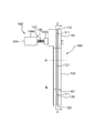
- FIG. 6 is a front view schematically showing a button component transport apparatus according to an embodiment of the present invention.
- FIG. 7 is a schematic side view of the button component transport device as seen from the direction of arrow C in FIG.
- FIG. 8 is a cross-sectional view of the intermediate curved path along the line DD in FIG.
- FIG. 9 is a cross-sectional view of the upper straight path along the line EE in FIG.
- FIG. 10 is a cross-sectional view of the intermediate curved path along the line FF in FIG.
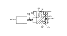
- FIG. 11 is a partial cross-sectional explanatory diagram for explaining the operation of the single supply mechanism, and shows a state where the first stopper is in the first position and the second stopper is in the retracted position.
- FIG. 7 is a schematic side view of the button component transport device as seen from the direction of arrow C in FIG.
- FIG. 8 is a cross-sectional view of the intermediate curved path along the line DD in FIG.
- FIG. 9 is a
- FIG. 12 is a partial cross-sectional explanatory diagram for explaining the operation of the single supply mechanism, showing a state in which the first stopper is in the second position and the second stopper is in the protruding position.
- FIG. 13 is a partial cross-sectional explanatory view showing a state where the button parts (bars) accumulated in the downward straight path do not exceed the mirror product amount confirmation line.
- FIG. 14 is a partial cross-sectional explanatory view showing a state where the bar accumulated in the downward straight path exceeds the mirror product amount confirmation line.
- FIG. 15 shows a modified example in which an escape portion is provided on the upper straight path, and the movable member is in the initial position.
- FIG. 16 shows a modification in which an escape portion is provided on the upper straight path, and the movable member is in the retracted position.
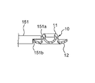
- FIG. 17 is an enlarged cross-sectional view of the movable member in the retracted position and the second bar from the bottom.
- FIG. 6 is a front view schematically showing the button component transport apparatus 100 according to one embodiment of the present invention.
- FIG. 7 is a schematic side view of the button component transport apparatus 100 as seen from the direction of arrow C in FIG.
- the button component conveying device 100 is provided between a hopper unit 70 that is a supply source of button components that is disposed relatively above, and a processing unit 80 of the button attachment machine that is below the hopper unit 70, The button parts are conveyed from the hopper unit 70 to the processing unit 80 by its own weight.
- this invention is not limited to the form which conveys button parts by dead weight, The form which conveys button parts by air regardless of dead weight, or the form which conveys button parts by air in addition to dead weight is included.
- the hopper unit 70 is loaded with a large number of button parts of the same type.
- the hopper unit 70 is rotated by a rotation drive source (not shown), and continuously supplies the button parts to an upper straight path 110 (to be described later) of the button part transport apparatus 100 while keeping the front and back of the button parts constant.
- the processing unit 80 includes an attachment part including an upper die and a lower die, and a supply part immediately before supplying a button body and a button stopper as button parts to the attachment part. Is attached to the fabric.
- the button component conveying apparatus 100 supplies the button component to the supply unit immediately before the processing unit 80.
- the button component conveying device 100 is configured to receive the button components from the hopper unit 70 continuously, and to linearly extend the upper straight path 110, to supply the button components to the processing unit 80, and to linearly extend the lower straight path 120. And an intermediate curved path 130 that connects the lower straight paths 110 and 120 in a curved shape, and a single supply mechanism 140 provided in the upper straight path 110. 6 and 7, the broken line A represents the boundary between the upper straight path 110 and the middle curved path 130, and the broken line B represents the boundary between the middle curved path 130 and the lower straight path 120.
- the upper and lower straight paths 110 and 120 are paths that send button components to the intermediate curved path 130 and the processing unit 80 while temporarily storing a plurality of button parts, respectively.
- the path 130 is a path that allows the button parts to pass through the lower straight path 120 one by one without accumulating button parts.
- FIG. 8 is a cross-sectional view of the intermediate curved path 130 along the line DD in FIG. 7, in which the lower end part of the upper straight path 110 and the upper end part of the lower straight path 120 are both represented.
- the upper straight path 110 receives button parts from the upper end or an inlet 112 near the upper end from the hopper unit 70, passes the button parts through a first passage 111 (see FIG. 7 and the like) extending in the longitudinal direction, and is supplied by a single supply mechanism 140.
- the button components are discontinuously delivered one by one from the lower end outlet 113 to the upper end inlet 132 of the intermediate curved path 130.
- the intermediate curved path 130 allows the button parts received from the upper straight path 110 to pass through the second passage 131 (see FIG. 7 and the like) extending in the longitudinal direction all at once without collecting or stopping the button parts, and from the outlet 133 at the lower end.
- the button part is delivered to the inlet 122 at the upper end of the lower straight path 120.
- the lower straight path 120 passes the button part received from the intermediate curved path 130 through the third passage extending in the longitudinal direction, and stores one button part from the lower end or the outlet 123 near the lower end to the processing unit 80 while accumulating a plurality of button parts. Supply one by one.
- route of the lower straight path 120 is 1st.
- the passage 111 is also referred to, and the description of the first passage 111 described later also applies to the third passage.
- the outlet 113 at the lower end of the upper straight path 110 and the inlet 132 at the upper end of the intermediate curved path 130 are adjacent to each other at the boundary A (see FIGS. 6 and 7), and the outlet 133 at the lower end of the intermediate curved path 130 and the lower straight path
- the upper end inlet 122 is adjacent to the boundary B (see FIGS. 6 and 7).
- FIG. 9 is a sectional view of the upper straight path 110 along the line EE in FIG.
- FIG. 10 is a cross-sectional view of the intermediate curved path 130 along the line FF in FIG.
- the lower straight path 120 has substantially the same form as the upper straight path 110 except for the length in the longitudinal direction. Therefore, it can be said that FIG. 9 is a sectional view of the downward straight path 120.
- the first and second passages 111 and 131 will be described with reference to FIGS. 9 and 10, and the vertical and horizontal directions of the first and second passages 111 and 131 are the same as those in FIGS. 9 and 10. Based on. Further, hereinafter, the bar 10 of FIG. 1 is used as an example of the button part.
- the bar 10 has a dome portion 11 that is a central portion and a flange portion 12 that is an extended portion.
- the first passage 111 has a first central groove 111a for passing the dome part 11 of the bar 10 and a first extension groove for passing the flange part 12 of the bar 10 extending from the upper end of the first central groove 111a to the left and right. 111b.
- the lower end of the first central groove 111 a opens to the outside of the upper straight path 110.
- the upper straight path 110 is formed by joining the left half body 110a and the right half body 110b, and half parts of the first passage 111 are formed on the side parts of the left half body 110a and the right half body 110b facing each other. .
- the second passage 131 is composed of a second central groove 131a for passing the dome portion 11 of the bar 10 and a second expansion groove 131b for passing the flange portion 12 in the same manner as the first passage 111.
- the lower end of the groove 131a opens to the outside of the intermediate curved path 130.
- the intermediate curved path 130 is formed by joining the left half 130a and the right half 130b, and the half of the second passage 131 is formed on the side of the left half 130a and the right half 130b facing each other.
- the second central groove 131 a of the second passage 131 has substantially the same dimensions as the first central groove 111 a of the first passage 111.
- the thickness (vertical interval) t2 of the second expansion groove 131b of the second passage 131 is set to be slightly larger than the thickness t1 of the first expansion groove 111b of the first passage 111. That is, t2> t1.
- the thicknesses t1 and t2 of the first and second expansion grooves 111b and 131b are set so that the flange portions 12 of the two adjacent bars 10 in the transport direction (longitudinal direction) are in the lateral direction perpendicular to the transport direction. It is set to a size that can pass without overlapping each other.
- the single supply mechanism 140 is provided in the middle of the upper straight path 110, but may be provided immediately before the intermediate curved path 130 in the upper straight path 110.
- 11 and 12 are partial cross-sectional explanatory views for explaining the operation of the single supply mechanism 140.
- the single supply mechanism 140 includes a first stopper 141 that can be displaced between a first position shown in FIG. 11 and a second position shown in FIG. 12, a retracted position shown in FIG. 11, and a protruding position shown in FIG.
- the left-right direction of the single supply mechanism 140 is based on the paper surface of FIGS.
- the stopper displacement mechanism 143 includes a solenoid 144 having a fixed portion 144a and a movable portion 144b, and a spring 145 for returning the movable portion 144b to the initial position shown in FIG. It is not limited to.
- the first and second stoppers 141 and 142 are connected to the movable portion 144b of the solenoid 144 and are displaced together with the movable portion 144b.
- the fixed portion 144a of the solenoid 144 is instantaneously energized
- the movable portion 144b at the initial position is sucked by the fixed portion 144a and displaced leftward to the suction position shown in FIG.
- the first stopper 141 located at the first position is displaced to the second position
- the second stopper located at the retracted position is displaced to the protruding position.
- the spring 145 is compressed between the fixed portion 144a and the movable portion 144b.
- the spring 145 Due to this compression, a restoring force is generated in the spring 145. Therefore, as soon as the spring 145 is compressed, the spring 145 expands due to the restoring force and returns to the initial state. As a result, the first stopper 141 located at the second position is displaced to the first position, and the second stopper located at the protruding position is displaced to the retracted position.
- the energization of the fixing portion 144a of the solenoid 144 can be interlocked with a foot switch that the operator steps on when the bar 10 is attached to the fabric by the processing portion 80 of the button attaching machine.
- the first stopper 141 protrudes into the first expansion groove 111b of the first passage 111 of the upper straight path 110 at the first position (see FIG. 11).
- the bar 10 is prevented from falling downward by the first stoppers 141. Therefore, the plurality of bars 10 are accumulated so as to be stacked upward from the first stopper 141.
- the lowest one, that is, the one in contact with the first stopper 141 is defined as a bar 10a
- the second one from the bottom adjacent to the upper side of the bar 10a is defined as a bar 10b.
- the movable portion 144b is attracted to the left, and the first stopper 141 is displaced to the second position as shown in FIG. 12, and at the same time, the second stopper is displaced to the protruding position.
- the first stopper 141 is displaced to the second position, the lowermost bar 10a is allowed to fall and released to the intermediate curved path 130. Further, the second stopper is displaced to the protruding position, so that the second bar 10b from the bottom is prevented from falling downward.
- the second stopper 142 becomes the retracted position and the first stopper 141 becomes the first position.
- the single supply mechanism 140 can supply the bars 10 one by one to the intermediate curved path 130 while accumulating the plurality of bars 10 in the upper straight path 110.
- the mirror 160 is arranged at the upper end portion of the lower straight path 120, and the component amount confirmation line 161 (see FIG. 7) is attached to the mirror 160. The operator can easily see the accumulation state of the bar 10 in the downward straight path 120 by the mirror 160, and whether or not the accumulated bar 10 exceeds the component amount confirmation line 161 by the component amount confirmation line 161 reflected on the mirror 160. It can be easily confirmed.
- FIG. 13 shows a state where the plurality of bars 10 accumulated in the lower straight path 120 does not exceed the component amount confirmation line 161 reflected on the mirror 160, and the lower straight path 120 is represented by a cross section along the first central groove 111a. Is done.
- the uppermost bar 10 accumulated in the lower straight path 120 is reflected in the mirror 160, but since this bar 10 does not exceed the part quantity confirmation line 161, the operator continues normal button mounting work. can do.
- FIG. 14 shows a state where the bar 10 accumulated in the lower straight path 120 exceeds the component amount confirmation line 161.
- FIGS. 15 and 16 are cross-sectional views similar to FIGS. 11 and 12 showing modifications of the above-described upper conveyance path 110.
- FIG. This modification is different from the above-described embodiment in that the escape portion 150 is added to the upper conveyance path 110.
- subjected to FIG.11, FIG.12 etc. is used for FIG.15 and FIG.16.
- the first stopper 141 in the first position stops the lowermost bar 10a from dropping, and the second stopper 142 is in the retracted position.
- the stopper displacement mechanism 143 is operated from this state, the first stopper 141 is displaced to the second position as shown in FIG.
- the second stopper 142 is moved from the retracted position. Displacement to the protruding position stops the fall of the second bar 10b from the bottom.
- the second stopper 142 is displaced to the protruding position, the second stopper 142 contacts the second bar 10b from the bottom, and the second bar 10b from the bottom is pressed against the inner wall defining the first passage 111, There is a possibility that the surface of the bar 10b may be damaged, or plating or painting may be damaged.
- the second bar 10b from the bottom escapes upward even if it is struck by the second stopper 142 that is displaced to the protruding position.
- the second bar 10b from the bottom contacts another bar 10 stacked upward, and this may damage the surface of the bar 10b, or may damage the plating and coating.
- an escape portion 150 is provided in the upper straight path 110 for allowing the second bar 10b from the bottom to escape in the lateral direction when the second stopper 142 is displaced to the protruding position.
- the escape portion 150 is an example of a movable member 151 that can be displaced from the initial position to a retracted position that is shifted from the initial position, and an elastic member that urges the movable member 151 in the retracted position to return to the initial position.
- a spring 152 In this example, the displacement direction of the movable member 151 from the initial position to the withdrawal position is along the lateral direction perpendicular to the longitudinal direction of the first straight path 110, but is not limited thereto, and is oblique to the longitudinal direction. May be the direction.
- FIG. 17 is an enlarged cross-sectional view of the movable member 151 in the retracted position and the bar 10 as the second bar 10b from the bottom.
- the movable member 151 includes an upper side portion 151 a that faces the dome portion 11 of the bar 10 from the side, and a lower side portion 151 b that faces the flange portion 12 of the bar 10 from the side.
- the movable member 151 is in contact with the bar 10 at least one of the upper side portion 151a and the lower side portion 151b at least in the retracted position.
- the movable member 151 In the retracted position of the second stopper 142 in FIG. 15, the movable member 151 is in the initial position. At the initial position of the movable member 151, the second bar 10b from the bottom is in contact with or close to the movable member 151.
- the second stopper 142 When the second stopper 142 is displaced from the retracted position to the projecting position and the second bar 10b from the bottom is projected by the second stopper 142 and displaced, the second bar 10b from the bottom is movable as shown in FIG. 151 is pushed so as to deviate from the initial position, whereby the movable member 151 is moved to the retracted position.
- the second bar 10b from the bottom projected by the second stopper 142 that is displaced to the projecting position can be temporarily released laterally while pushing the movable member 151, thereby damaging the bar 10b. Can be prevented.
- the movable member 151 As soon as the movable member 151 is displaced to the retracted position, the movable member 151 returns to the initial position by the spring 152.
- the present invention is directed to the female snap button 30, the male snap button 50, and the rivet 20 as the button stop shown in FIG.
- the present invention can also be applied to the button fasteners 40 and 60 shown in FIGS. 2, 3 and 5, the fastener body 61 which is a part of the button fastener 60 shown in FIG. 5, and the like.
Landscapes
- Engineering & Computer Science (AREA)
- Textile Engineering (AREA)
- Feeding Of Articles To Conveyors (AREA)
- Sewing Machines And Sewing (AREA)
Abstract
L'invention concerne un dispositif de transfert d'élément de bouton au moyen duquel il est possible d'éliminer le coinçage ou l'échec de passage d'un élément de bouton. Le dispositif de transfert d'élément de bouton (100) transfère un élément de bouton (10) d'une source d'alimentation (70) à une unité de traitement (80). Le dispositif de transfert d'élément de bouton (100) comprend : un trajet linéaire supérieur (110) qui reçoit l'élément de bouton (10) depuis la source d'alimentation (70) ; un trajet linéaire inférieur (120) qui fournit l'élément de bouton (10) à l'unité de traitement (80) ; un trajet incurvé central (130) reliant les trajets linéaires supérieur et inférieur (110, 120) ; et un mécanisme d'alimentation individuel (140) pour fournir l'élément de bouton (10) au trajet incurvé central (130) un par un, tout en accumulant temporairement une pluralité d'éléments de bouton (10) dans le trajet linéaire supérieur (110). Le trajet incurvé central (130) permet à l'élément de bouton (10) fourni par le trajet linéaire supérieur (110) un par un d'être passé au trajet linéaire inférieur (130).
Priority Applications (2)
| Application Number | Priority Date | Filing Date | Title |
|---|---|---|---|
| PCT/JP2018/013855 WO2019187095A1 (fr) | 2018-03-30 | 2018-03-30 | Dispositif de transfert d'élément de bouton |
| TW107126258A TW201942035A (zh) | 2018-03-30 | 2018-07-30 | 鈕扣零件搬運裝置 |
Applications Claiming Priority (1)
| Application Number | Priority Date | Filing Date | Title |
|---|---|---|---|
| PCT/JP2018/013855 WO2019187095A1 (fr) | 2018-03-30 | 2018-03-30 | Dispositif de transfert d'élément de bouton |
Publications (1)
| Publication Number | Publication Date |
|---|---|
| WO2019187095A1 true WO2019187095A1 (fr) | 2019-10-03 |
Family
ID=68058672
Family Applications (1)
| Application Number | Title | Priority Date | Filing Date |
|---|---|---|---|
| PCT/JP2018/013855 Ceased WO2019187095A1 (fr) | 2018-03-30 | 2018-03-30 | Dispositif de transfert d'élément de bouton |
Country Status (2)
| Country | Link |
|---|---|
| TW (1) | TW201942035A (fr) |
| WO (1) | WO2019187095A1 (fr) |
Citations (4)
| Publication number | Priority date | Publication date | Assignee | Title |
|---|---|---|---|---|
| US4354588A (en) * | 1978-12-30 | 1982-10-19 | Schaeffer-Homberg Gmbh | Device on an attachment machine |
| JPS59145529U (ja) * | 1983-03-18 | 1984-09-28 | 日本ノ−ション工業株式会社 | 部品減速装置を備えた釦加工装置 |
| JPH09107196A (ja) * | 1995-10-09 | 1997-04-22 | Sony Corp | 部品供給方法及びその装置 |
| JP2001192106A (ja) * | 2000-01-07 | 2001-07-17 | Taiyo Yuden Co Ltd | 部品配向構造 |
-
2018
- 2018-03-30 WO PCT/JP2018/013855 patent/WO2019187095A1/fr not_active Ceased
- 2018-07-30 TW TW107126258A patent/TW201942035A/zh unknown
Patent Citations (4)
| Publication number | Priority date | Publication date | Assignee | Title |
|---|---|---|---|---|
| US4354588A (en) * | 1978-12-30 | 1982-10-19 | Schaeffer-Homberg Gmbh | Device on an attachment machine |
| JPS59145529U (ja) * | 1983-03-18 | 1984-09-28 | 日本ノ−ション工業株式会社 | 部品減速装置を備えた釦加工装置 |
| JPH09107196A (ja) * | 1995-10-09 | 1997-04-22 | Sony Corp | 部品供給方法及びその装置 |
| JP2001192106A (ja) * | 2000-01-07 | 2001-07-17 | Taiyo Yuden Co Ltd | 部品配向構造 |
Also Published As
| Publication number | Publication date |
|---|---|
| TW201942035A (zh) | 2019-11-01 |
Similar Documents
| Publication | Publication Date | Title |
|---|---|---|
| KR100593371B1 (ko) | 개선된 체결장치 | |
| JP4817594B2 (ja) | ワークステーションに定型物体を供給する方法および装置 | |
| US11840412B2 (en) | Handling system for the automatic transfer and separation of load carriers | |
| CN102458757A (zh) | 用于供应连接元件的设备的单个化滑动件 | |
| US20120210890A1 (en) | Lifting apparatus with safety device | |
| JP6198743B2 (ja) | 作業装置 | |
| JP2011527275A (ja) | 構成部品の自動分配装置 | |
| WO2019187095A1 (fr) | Dispositif de transfert d'élément de bouton | |
| CN111683761B (zh) | 用于紧固件设置机的紧固件处理装置及相关方法 | |
| TWI507147B (zh) | Method of manufacturing parts feeders and zippers | |
| JP2011058421A (ja) | 弁コッタ及びリテーナの組付け装置 | |
| KR20140144426A (ko) | 리베팅 자동화 장치 | |
| DE69524168T2 (de) | Gerät zum kontinuierlichen Fördern und Setzen von vernichtbaren Muttern | |
| JP2018193156A (ja) | パーツフィーダ | |
| KR102491953B1 (ko) | 리벳 분배 시스템 및 이의 사용 방법 | |
| SK51396A3 (en) | Device for use in a press to feed connecting components and secure them in workpieces by pressing | |
| JP2019099279A (ja) | 重力コンベア装置、トレイ、及び自動倉庫 | |
| TWI523803B (zh) | 零件供給裝置 | |
| US6736255B1 (en) | Conveyor system for feeding small parts to a chain assembly unit | |
| JP5499962B2 (ja) | 部品整列供給方法 | |
| GB2033815A (en) | Escapement assembly for fastening feeding apparatus | |
| US6564923B2 (en) | Separating device | |
| JP4694212B2 (ja) | 物流用棚装置 | |
| JPH0425331A (ja) | 引張りコイルスプリングの自動組付け装置 | |
| JP4625479B2 (ja) | リベッター用のリベット位置決ユニット、及びリベッター |
Legal Events
| Date | Code | Title | Description |
|---|---|---|---|
| 121 | Ep: the epo has been informed by wipo that ep was designated in this application |
Ref document number: 18911480 Country of ref document: EP Kind code of ref document: A1 |
|
| 122 | Ep: pct application non-entry in european phase |
Ref document number: 18911480 Country of ref document: EP Kind code of ref document: A1 |
|
| NENP | Non-entry into the national phase |
Ref country code: JP |