WO2019187147A1 - 刈払機 - Google Patents
刈払機 Download PDFInfo
- Publication number
- WO2019187147A1 WO2019187147A1 PCT/JP2018/013961 JP2018013961W WO2019187147A1 WO 2019187147 A1 WO2019187147 A1 WO 2019187147A1 JP 2018013961 W JP2018013961 W JP 2018013961W WO 2019187147 A1 WO2019187147 A1 WO 2019187147A1
- Authority
- WO
- WIPO (PCT)
- Prior art keywords
- brush cutter
- box
- absorbing member
- shaft
- ribs
- Prior art date
- Legal status (The legal status is an assumption and is not a legal conclusion. Google has not performed a legal analysis and makes no representation as to the accuracy of the status listed.)
- Ceased
Links
Images



Classifications
-
- A—HUMAN NECESSITIES
- A01—AGRICULTURE; FORESTRY; ANIMAL HUSBANDRY; HUNTING; TRAPPING; FISHING
- A01G—HORTICULTURE; CULTIVATION OF VEGETABLES, FLOWERS, RICE, FRUIT, VINES, HOPS OR SEAWEED; FORESTRY; WATERING
- A01G3/00—Cutting implements specially adapted for horticultural purposes; Delimbing standing trees
- A01G3/06—Hand-held edge trimmers or shears for lawns
- A01G3/062—Motor-driven edge trimmers
-
- A—HUMAN NECESSITIES
- A01—AGRICULTURE; FORESTRY; ANIMAL HUSBANDRY; HUNTING; TRAPPING; FISHING
- A01D—HARVESTING; MOWING
- A01D34/00—Mowers; Mowing apparatus of harvesters
- A01D34/835—Mowers; Mowing apparatus of harvesters specially adapted for particular purposes
- A01D34/90—Mowers; Mowing apparatus of harvesters specially adapted for particular purposes for carrying by the operator
- A01D34/905—Vibration dampening means
-
- B—PERFORMING OPERATIONS; TRANSPORTING
- B25—HAND TOOLS; PORTABLE POWER-DRIVEN TOOLS; MANIPULATORS
- B25F—COMBINATION OR MULTI-PURPOSE TOOLS NOT OTHERWISE PROVIDED FOR; DETAILS OR COMPONENTS OF PORTABLE POWER-DRIVEN TOOLS NOT PARTICULARLY RELATED TO THE OPERATIONS PERFORMED AND NOT OTHERWISE PROVIDED FOR
- B25F5/00—Details or components of portable power-driven tools not particularly related to the operations performed and not otherwise provided for
- B25F5/006—Vibration damping means
-
- B—PERFORMING OPERATIONS; TRANSPORTING
- B25—HAND TOOLS; PORTABLE POWER-DRIVEN TOOLS; MANIPULATORS
- B25F—COMBINATION OR MULTI-PURPOSE TOOLS NOT OTHERWISE PROVIDED FOR; DETAILS OR COMPONENTS OF PORTABLE POWER-DRIVEN TOOLS NOT PARTICULARLY RELATED TO THE OPERATIONS PERFORMED AND NOT OTHERWISE PROVIDED FOR
- B25F5/00—Details or components of portable power-driven tools not particularly related to the operations performed and not otherwise provided for
- B25F5/02—Construction of casings, bodies or handles
- B25F5/025—Construction of casings, bodies or handles with torque reaction bars for rotary tools
- B25F5/026—Construction of casings, bodies or handles with torque reaction bars for rotary tools in the form of an auxiliary handle
-
- F—MECHANICAL ENGINEERING; LIGHTING; HEATING; WEAPONS; BLASTING
- F16—ENGINEERING ELEMENTS AND UNITS; GENERAL MEASURES FOR PRODUCING AND MAINTAINING EFFECTIVE FUNCTIONING OF MACHINES OR INSTALLATIONS; THERMAL INSULATION IN GENERAL
- F16F—SPRINGS; SHOCK-ABSORBERS; MEANS FOR DAMPING VIBRATION
- F16F1/00—Springs
- F16F1/36—Springs made of rubber or other material having high internal friction, e.g. thermoplastic elastomers
- F16F1/373—Springs made of rubber or other material having high internal friction, e.g. thermoplastic elastomers characterised by having a particular shape
- F16F1/376—Springs made of rubber or other material having high internal friction, e.g. thermoplastic elastomers characterised by having a particular shape having projections, studs, serrations or the like on at least one surface
-
- F—MECHANICAL ENGINEERING; LIGHTING; HEATING; WEAPONS; BLASTING
- F16—ENGINEERING ELEMENTS AND UNITS; GENERAL MEASURES FOR PRODUCING AND MAINTAINING EFFECTIVE FUNCTIONING OF MACHINES OR INSTALLATIONS; THERMAL INSULATION IN GENERAL
- F16F—SPRINGS; SHOCK-ABSORBERS; MEANS FOR DAMPING VIBRATION
- F16F1/00—Springs
- F16F1/36—Springs made of rubber or other material having high internal friction, e.g. thermoplastic elastomers
- F16F1/373—Springs made of rubber or other material having high internal friction, e.g. thermoplastic elastomers characterised by having a particular shape
- F16F1/377—Springs made of rubber or other material having high internal friction, e.g. thermoplastic elastomers characterised by having a particular shape having holes or openings
-
- F—MECHANICAL ENGINEERING; LIGHTING; HEATING; WEAPONS; BLASTING
- F16—ENGINEERING ELEMENTS AND UNITS; GENERAL MEASURES FOR PRODUCING AND MAINTAINING EFFECTIVE FUNCTIONING OF MACHINES OR INSTALLATIONS; THERMAL INSULATION IN GENERAL
- F16F—SPRINGS; SHOCK-ABSORBERS; MEANS FOR DAMPING VIBRATION
- F16F15/00—Suppression of vibrations in systems; Means or arrangements for avoiding or reducing out-of-balance forces, e.g. due to motion
- F16F15/02—Suppression of vibrations of non-rotating, e.g. reciprocating systems; Suppression of vibrations of rotating systems by use of members not moving with the rotating systems
- F16F15/04—Suppression of vibrations of non-rotating, e.g. reciprocating systems; Suppression of vibrations of rotating systems by use of members not moving with the rotating systems using elastic means
- F16F15/08—Suppression of vibrations of non-rotating, e.g. reciprocating systems; Suppression of vibrations of rotating systems by use of members not moving with the rotating systems using elastic means with rubber springs ; with springs made of rubber and metal
-
- A—HUMAN NECESSITIES
- A01—AGRICULTURE; FORESTRY; ANIMAL HUSBANDRY; HUNTING; TRAPPING; FISHING
- A01D—HARVESTING; MOWING
- A01D34/00—Mowers; Mowing apparatus of harvesters
- A01D34/01—Mowers; Mowing apparatus of harvesters characterised by features relating to the type of cutting apparatus
- A01D34/412—Mowers; Mowing apparatus of harvesters characterised by features relating to the type of cutting apparatus having rotating cutters
- A01D34/416—Flexible line cutters
Definitions
- the present invention relates to a brush cutter, and more particularly, to a brush cutter provided with a vibration absorbing member.
- a brush cutter such as an engine, a working unit such as a cutting blade that is driven by the power of the drive unit, a shaft that transmits the power of the drive unit, and the drive unit and the work unit are disposed inside.
- a brush cutter is known that includes a cylindrical portion through which a shaft is inserted and a handle supported by the cylindrical portion.
- Patent Document 1 discloses a brush cutter that suppresses vibration generated in a shaft by integrally attaching a resin bush to the shaft inside a cylindrical portion.
- the present invention provides a brush cutter that can suppress vibration transmitted from a drive unit or a working unit to a cylinder unit from being transmitted to a handle.
- the present invention A drive unit; A working unit driven by the power of the driving unit; A shaft for transmitting the power of the driving unit to the working unit; A cylindrical portion disposed between the drive portion and the working portion, and through which the shaft is inserted; A floating box having a handle support; A brush cutter comprising: a handle supported by the handle support; The brush cutter includes a vibration absorbing member that fits into a cylinder side fitting part provided in the cylinder part and fits into a box side fitting part provided in the floating box, The vibration absorbing member is An inner peripheral surface of which an inner peripheral surface is in contact with the tubular portion side fitting portion; An outer peripheral portion whose outer peripheral surface abuts on the box side fitting portion; A plurality of ribs connecting the inner periphery and the outer periphery; A pair of stopper portions protruding from the outer peripheral portion toward the inner peripheral portion and opposed to the inner peripheral portion via a gap portion; The pair of stopper portions are arranged at positions perpendicular to the upper and lower surfaces passing through the center of the handle
- the floating box provided with the handle support portion and the cylinder portion through which the shaft for transmitting the power of the drive portion to the work portion is fitted through the vibration absorbing member, the drive portion and work
- the vibration transmitted from the part to the cylinder part can be suppressed from being transmitted to the handle.
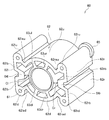
- FIG. 4 is a right side view of the vibration absorbing member of FIG. 3.
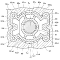
- FIG. 2 is a cross-sectional view taken along the line AA in FIG.
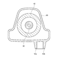
- FIG. 2 is a cross-sectional view of a main part BB in FIG. 1.
- the brush cutter 1 includes a drive unit 10, a working unit 20 that is driven by the power of the drive unit 10, a shaft 30 that transmits the power of the drive unit 10 to the work unit 20, and a drive
- the cylinder part 40 which is arrange
- the working unit 20 may be a rotary cutting blade, for example, but is not particularly limited.
- the handle 90 is provided with grips 91 ⁇ / b> L and 91 ⁇ / b> R that are held by the operator during work, and on one side (the grip 91 ⁇ / b> R in the illustrated example) is provided with a throttle lever 92 that adjusts the power of the drive unit 10.
- the power by the drive unit 10 is transmitted when the clutch 11 is connected to the output shaft of the drive unit 10, and the power transmitted to the clutch 11 is a shaft 30 (see FIG. 2) provided inside the cylinder unit 40. ) To the working unit 20.
- the working unit 20 side is the distal end side
- the drive unit 10 side is the proximal end side
- the side on which the handle support unit 51 is provided is the upper side and the opposite side. Will be described below.
- a first holding portion 41 is provided at the base end side end portion of the cylinder portion 40, that is, the drive portion 10 side end portion.
- the first holding part 41 is connected to the driving part 10, covers the clutch 11, and is provided so as to surround the outer periphery of the cylinder part 40. Further, the first holding portion 41 is provided with pin-shaped tubular portion side fitting portions 41 a extending in parallel to the shaft 30 toward the tip side on the top and bottom of the shaft 30.
- a second holding portion 42 is provided on the distal end side from the proximal end side end portion of the cylindrical portion 40 to about one third of the axial length of the cylindrical portion 40.
- the second holding portion 42 is provided so as to surround the outer periphery of the cylindrical portion 40.
- the second holding portion 42 is provided with a pin-shaped tubular portion side fitting portion 42 a extending toward the base end side in parallel with the shaft 30 on the top and bottom of the shaft 30.
- the floating box 50 is arranged so that both ends are sandwiched between the first holding part 41 and the second holding part 42.
- a handle support portion 51 is provided on the top end of the floating box 50 (on the second holding portion 42 side), and the handle 90 is supported by the handle support portion 51.
- the floating box 50 is provided with a total of four hole-shaped box-side fitting portions 52 extending in parallel with the shaft 30 above and below the shafts 30 at both ends in the axial direction of the floating box 50.
- box-side fitting portion 52 has a tapered shape in which the inner peripheral surface 52a has a vertical distance that decreases from both axial ends of the floating box 50 toward the center when viewed from the direction orthogonal to the shaft 30. have.
- the outer periphery of the cylinder part side fitting part 41a and the cylinder part side fitting part 42a is each fitting with the vibration absorption member 60, and the outer periphery of this vibration absorption member 60 is with the box side fitting part 52. It is mated. Therefore, the floating box 50 is supported by the first holding part 41 and the second holding part 42 provided in the cylindrical part 40 via the vibration absorbing member 60.
- the floating box 50 provided with the handle support portion 51 and the cylindrical portion 40 through which the shaft 30 for transmitting the power of the driving portion 10 to the working portion 20 is fitted via the vibration absorbing member 60,
- the vibration transmitted from the drive unit 10 or the working unit 20 to the tube unit 40 can be suppressed from being transmitted to the handle 90.
- the vibration absorbing member 60 includes an inner peripheral portion 61, an outer peripheral portion 62, two upper ribs 63 ul and 63 ur that connect the inner peripheral portion 61 and the outer peripheral portion 62, and two lower ribs 63 dl. , 63dr.
- the vibration absorbing member 60 is made of an elastic material, and for example, rubber can be used, but is not particularly limited.
- the inner periphery 61 has an annular shape.
- the outer peripheral part 62 includes an upper arc part 62u and a lower arc part 62d that are concentric with the inner peripheral part 61, a left connecting part 62l that connects the left side of the upper arc part 62u and the left side of the lower arc part 62d, A right connecting part 62r that connects the right side of the arc part 62u and the right side of the lower arc part 62d;
- the left connecting part 62l connects the left upper end annular part 62lu and the left lower end annular part 62ld having a central axis parallel to the central axis of the inner peripheral part 61, and the left upper end annular part 62lu and the left side of the upper arc part 62u. Connecting the upper left arc connecting portion 62 lau, the lower left arc connecting portion 62 ld connecting the left lower end circular portion 62 ld and the left lower arc portion 62 d, and the upper left upper ring portion 62 lu and the lower left annular portion 62 ld. Left upper and lower connecting portion 62lb. Further, the left upper and lower connecting portion 62 lb is provided with a left stopper portion 64 l that protrudes toward the inner peripheral portion 61.
- the right connecting portion 62r connects the upper right end annular portion 62ru and the right lower end annular portion 62rd having a central axis parallel to the central axis of the inner peripheral portion 61, and the right side of the upper right end annular portion 62ru and the upper arc portion 62u.
- Right upper and lower connecting part 62rb to be connected.
- the right upper / lower connecting portion 62rb is provided with a right stopper portion 64r protruding toward the inner peripheral portion 61.
- left stopper portion 64l and the right stopper portion 64r are provided at positions facing each other across the upper and lower surfaces passing through the center of the ring of the inner peripheral portion 61, and between the inner peripheral portion 61 and the left stopper portion 64l.
- the gap portion Cl is provided between the inner peripheral portion 61 and the right stopper portion 64r, respectively.
- the upper ribs 63 ul and 63 ur respectively connect the upper side from the center of the ring of the inner peripheral part 61 and the upper arc part 62 u of the outer peripheral part 62.
- the upper rib 63ul is provided on the left side of the upper and lower surfaces passing through the center of the inner periphery 61
- the upper rib 63ur is provided on the right side of the upper and lower surfaces of the inner periphery 61 passing through the center of the ring.
- the upper rib 63ur is a pair with the upper and lower surfaces passing through the center of the ring of the inner peripheral portion 61 interposed therebetween.
- the lower ribs 63dl and 63dr connect the lower side from the center of the ring of the inner peripheral part 61 and the lower arc part 62d of the outer peripheral part 62, respectively.
- the lower rib 63dl is provided on the left side of the upper and lower surfaces passing through the ring center of the inner peripheral portion 61
- the lower rib 63dr is provided on the right side of the upper and lower surfaces passing through the ring center of the inner peripheral portion 61.
- the rib 63dl and the lower rib 63dr are paired with an upper and lower surface passing through the center of the ring of the inner peripheral portion 61 interposed therebetween.
- the wall thickness of the left stopper portion 64l and the right stopper portion 64r is configured to be larger than the wall thickness of the upper ribs 63ul and 63ur and the lower ribs 63dl and 63dr.
- a lip portion 65 is provided on the end surface on one end side (the back side in the drawing) of the lower left annular portion 62ld and the upper right annular portion 62ru.
- Each of the lip portions 65 has a hook shape extending from the outer peripheral surfaces of the left lower end annular portion 62ld and the upper right end annular portion 62ru in the outer diameter direction of the annular center.
- the vibration absorbing member 60 is viewed from a direction orthogonal to the central axis of the annular portion of the inner peripheral portion 61 from the one end side (the right side in the drawing) where the lip portion 65 is provided (the figure). It has a taper shape whose vertical length becomes shorter toward the middle left). That is, it has a tapered shape such that the other end side vertical length D2 is smaller than the one end side vertical length D1.
- the vibration absorbing member 60 is arranged so that one end side where the lip portion 65 is provided becomes both end sides of the floating box 50, that is, the lip portion 65 is the first holding portion 41 or the second holding portion 42. Are fitted into the cylinder side fitting parts 41a and 42a and the box side fitting part 52.
- the vibration absorbing member 60 is provided with the lip portion 65 on the end face on one end side, the vibration absorbing member 60 is attached to the cylinder side fitting portions 41a and 42a and the box side fitting portion 52 during assembly.
- the fitting direction can be easily visually confirmed.
- the vibration absorbing member 60 is fitted to the tube side fitting portions 41 a and 42 a in the wrong direction, the vibration absorbing member 60 cannot be inserted into the box side fitting portion 52 by the lip portion 65. Therefore, misassembly can be prevented at the time of assembly.
- the inner peripheral portion 61 is fitted with the tube portion side fitting portion 42 a of the second holding portion 42. Further, the vibration absorbing member 60 is fitted and fixed to the box-side fitting portion 52 when the left connecting portion 62l and the right connecting portion 62r of the outer peripheral portion 62 are in contact with the inner peripheral surface 52a of the box-side fitting portion 52.
- the right upper and lower connecting portions 62rb and the right stopper portion 64r are in contact with the inner peripheral surface 52a of the box side fitting portion 52.
- the upper surfaces of the upper left annular portion 62lu and the upper right annular portion 62ru, and the lower surfaces of the lower left annular portion 62ld and the lower right annular portion 62rd are also in contact with the inner peripheral surface 52a of the box-side fitting portion 52.
- the vibration absorbing member 60 is fixed in the vertical direction and the horizontal direction.
- the loads in the upper and lower surfaces of the vibration absorbing member 60 are applied to the plurality of ribs. Can be dispersed.
- the brush cutter 1 is placed with the handle support portion 51 facing upward when not in use. At this time, stress concentration on a specific portion of the vibration absorbing member 60 is reduced by supporting gravity with a plurality of ribs. it can.
- an upper air gap Su and a lower air gap Sd are provided between the upper arc portion 62u and the lower arc portion 62d of the vibration absorbing member 60 and the inner peripheral surface 52a of the box side fitting portion 52.
- the outer peripheral portion 62 of the vibration absorbing member 60 is allowed to be deformed in the vertical direction. Therefore, the stress applied to the upper ribs 63ul and 63ur and the lower ribs 63dl and 63dr can be reduced, and the transmission of vibration to the handle 90 via the floating box 50 can be further reduced.
- the vibration absorbing member 60 is fitted and fixed to the box-side fitting portion 52 at the left connecting portion 62l and the right connecting portion 62r, and the upper arc portion 62u and the lower arc portion 62d, the upper ribs 63ul and 63ur, and the lower portion.
- the side ribs 63dl and 63dr are deformed to absorb vibrations.
- the upper and lower ribs 63ul and 63ur and the lower ribs 63dl and 63dr that allow deformation are appropriately damped by increasing the thickness of the left stopper portion 64l and the right stopper portion 64r that restrict deformation. can do.
- the box-side fitting portion 52 has a taper shape such that the inner peripheral surface 52a has a vertical distance that decreases from both axial ends of the floating box 50 toward the center when viewed from the direction orthogonal to the shaft 30.
- the vibration absorbing member 60 is also arranged in a direction in which the taper shape decreases in the vertical direction from both axial ends of the floating box 50 toward the center.
- the floating box 50 includes two convex holding portions 53 a and 53 b extending from the front end side of the floating box 50 in the axial direction of the shaft 30 on the side opposite to the handle support portion 51. .
- the operator can hold the brush cutter 1 and move with the hand so as to straddle the two gripping portions 53a and 53b, and the carryability of the brush cutter 1 is improved.
- each of the lip portions 65 has a hook shape extending from the outer peripheral surfaces of the left lower end annular portion 62ld and the upper right end annular portion 62ru in the outer radial direction of the annular center.
- the structure is simplified and the manufacture is facilitated.
- the left upper and lower connecting portions 62 lb and the right upper and lower connecting portions 62 rb extend in the vertical direction. It is good also as a character shape of "ku". If it does in this way, the shape of the inner peripheral surface 52a of the box side fitting part 52 is also made into the same shape,
- the vibration absorption member 60 can suppress that a shift
- a drive unit (drive unit 10); A working unit (working unit 20) driven by the power of the driving unit; A shaft (shaft 30) for transmitting the power of the drive unit to the working unit; A cylinder part (cylinder part 40) that is arranged between the drive part and the working part, and through which the shaft is inserted; A floating box (floating box 50) having a handle support (handle support 51); A brush cutter (a brush cutter 1) including a handle (handle 90) supported by the handle support portion; The brush cutter fits into a cylinder part side fitting part (cylinder part side fitting part 41a, 42a) provided in the cylinder part, and a box side fitting part (box side) provided in the floating box.
- the vibration absorbing member is An inner peripheral portion (inner peripheral portion 61) in which an inner peripheral surface is in contact with the tube portion side fitting portion; An outer peripheral portion (outer peripheral portion 62) whose outer peripheral surface is in contact with the box-side fitting portion; A plurality of ribs (upper ribs 63ul, 63ur, lower ribs 63dl, 63dr) connecting the inner peripheral part and the outer peripheral part; A pair of stopper parts (left stopper part 64l, right stopper part 64r) projecting from the outer peripheral part toward the inner peripheral part and facing the inner peripheral part via gap parts (gap parts Cl, Cr), Have The pair of stopper portions are arranged at positions perpendicular to the upper and lower surfaces passing through the center of the handle support portion and the center of the shaft, as viewed from the axial direction.
- the brush cutter wherein the plurality of ribs are disposed on both sides of the upper and lower surfaces and at positions
- the floating box provided with the handle support portion and the cylindrical portion through which the shaft that transmits the power of the drive portion to the working portion is fitted through the vibration absorbing member. It is possible to suppress the vibration transmitted from the working part to the cylinder part from being transmitted to the handle.
- the vibration absorbing member protrudes from the outer peripheral portion toward the inner peripheral portion, and a pair of stopper portions facing the inner peripheral portion via the gap portion are orthogonal to the upper and lower surfaces passing through the center of the handle support portion and the center of the shaft.
- the vibration absorbing member when the operator holds the handle and shakes the brush cutter to the left and right, if the vibration absorbing member is deformed by a certain amount in the direction perpendicular to the upper and lower surfaces, the inner peripheral portion comes into contact with the stopper portion, Deformation is regulated. Thereby, when the brush cutter is swung from side to side, the operator's uncomfortable feeling due to the deformation of the vibration absorbing member can be reduced. Further, since the plurality of ribs are arranged on both sides of the upper and lower surfaces at positions shifted from the upper and lower surfaces, the load in the upper and lower surface direction of the vibration absorbing member can be distributed to the plurality of ribs. Generally, the brush cutter is placed with the handle support portion facing upward when not in use. At this time, by supporting gravity with a plurality of ribs, stress concentration on a specific portion of the vibration absorbing member can be reduced.
- the plurality of ribs are: A pair of upper ribs (upper ribs 63ul, 63ur) provided above the center of the shaft across the upper and lower surfaces; A pair of lower ribs (lower ribs 63dl, 63dr) provided below the center of the shaft across the upper and lower surfaces,
- the inner peripheral portion has an annular shape surrounding the tubular portion side fitting portion,
- the outer periphery is An upper arc portion (upper arc portion 62u) connected to the pair of upper ribs; A lower arc portion connected to the pair of lower ribs (lower arc portion 62d); One end side connecting portion (left connecting portion 62l) for connecting one end side of the upper arc portion and one end side of the lower arc portion; The other end side of the upper arc part and the other end side connecting part (right side connecting part 62r) for connecting the other end side of the lower arc part, The one end side connecting portion and the other end side connecting portion are fitted to the box side fitting
- the vibration absorbing member is fitted and fixed to the box side fitting portion at the left side connecting portion and the right side connecting portion, and is deformed at the upper arc portion and the lower arc portion and the upper rib and the lower rib. And can absorb vibration.
- the brush cutter according to (1) or (2) has a wall thickness of the pair of stopper portions larger than a wall thickness of the plurality of ribs.
- the vibration and impact can be appropriately damped by increasing the thickness of the pair of stopper portions that restrict the deformation of the plurality of ribs that allow the deformation.
- a drive unit (drive unit 10); A working unit (working unit 20) driven by the power of the driving unit; A shaft (shaft 30) for transmitting the power of the drive unit to the working unit; A cylinder part (cylinder part 40) that is arranged between the drive part and the working part, and through which the shaft is inserted; A floating box (floating box 50) having a handle support (handle support 51); A brush cutter (a brush cutter 1) including a handle (handle 90) supported by the handle support portion; The brush cutter fits into a cylinder part side fitting part (cylinder part side fitting part 41a, 42a) provided in the cylinder part, and a box side fitting part (box side) provided in the floating box.
- a vibration absorbing member (vibration absorbing member 60) fitted to the fitting portion 52), A brush cutter in which an inner peripheral surface (inner peripheral surface 52a) of the box-side fitting portion and an outer peripheral surface of the vibration absorbing member have a tapered shape when viewed from a direction orthogonal to the axis.
- the vibration absorbing member since the floating box provided with the handle support part and the cylinder part through which the shaft for transmitting the power of the drive part to the working part is inserted are fitted via the vibration absorbing member, It is possible to suppress the vibration transmitted from the working part to the cylinder part from being transmitted to the handle.
- the inner peripheral surface of the box side fitting portion and the outer peripheral surface of the vibration absorbing member have a tapered shape when viewed from the direction orthogonal to the axis, the vibration absorbing member is attached to the box side fitting portion during assembly. Can be easily fitted to improve productivity.
- gap of the internal peripheral surface of a box side fitting part and a vibration absorption member can be made uniform, vibration absorption performance does not fall.
- the vibration absorbing member is provided with the lip portion on the end face on one end side, the vibration absorbing member is fitted to the tube side fitting portion and the box side fitting portion during assembly. The direction can be easily seen. Further, when the vibration absorbing member is fitted to the tube portion side fitting portion in the wrong direction, the vibration absorbing member cannot be inserted into the box side fitting portion by the lip portion. Therefore, misassembly can be prevented at the time of assembly.
- Predetermined gap portions (upper gap portion Su, lower gap portion Sd) are provided between the box-side fitting portion and the vibration absorbing member on the upper and lower surfaces passing through the center of the handle support portion and the center of the shaft.
- a brush cutter is provided.
- the upper and lower surfaces passing through the handle support portion and the center of the shaft have a predetermined gap between the box-side fitting portion and the vibration absorbing member, so that the outer peripheral portion of the vibration absorbing member is It is possible to allow deformation in the upper and lower surface directions. Thereby, the stress concerning a some rib can be reduced and it can further reduce that a vibration transmits to a handle
- the said floating box is a brush cutter which has the holding part (grip part 53a, 53b) extended in the said axial direction on the opposite side to the said handle
Landscapes
- Engineering & Computer Science (AREA)
- General Engineering & Computer Science (AREA)
- Mechanical Engineering (AREA)
- Life Sciences & Earth Sciences (AREA)
- Environmental Sciences (AREA)
- Forests & Forestry (AREA)
- Ecology (AREA)
- Biodiversity & Conservation Biology (AREA)
- Chemical & Material Sciences (AREA)
- Combustion & Propulsion (AREA)
- Physics & Mathematics (AREA)
- Acoustics & Sound (AREA)
- Aviation & Aerospace Engineering (AREA)
- Harvester Elements (AREA)
Abstract
駆動部(10)と、駆動部(10)の動力によって駆動する作業部(20)と、駆動部(10)の動力を作業部(20)に伝達する軸(30)と、駆動部(10)と作業部(20)との間に配置され、内部に軸(30)が挿通する筒部(40)と、ハンドル支持部(51)を有するフローティングボックス(50)と、ハンドル支持部(51)に支持されたハンドル(90)と、を備える刈払機(1)であって、刈払機(1)は、筒部(40)に設けられた筒部側嵌合部(41a、42a)に嵌合するとともに、フローティングボックス(50)に設けられたボックス側嵌合部(52)に嵌合する振動吸収部材(60)を備える。
Description
本発明は、刈払機に関し、特に、振動吸収部材を備えた刈払機に関する。
従来から、エンジン等の駆動部と、該駆動部の動力によって駆動する刈刃等の作業部と、駆動部の動力を伝達する軸と、駆動部と作業部との間に配置され、内部に軸が挿通する筒部と、筒部に支持されたハンドルを備える刈払機が知られている。
この種の刈払機では、駆動部や作業部からの振動がハンドルに伝わり難くなるように構成されているものがある。例えば、特許文献1には、筒部の内部で、樹脂製ブッシュを軸に一体的に取り付けることにより、軸に発生する振動を抑制する刈払機が開示されている。
しかしながら、特許文献1の刈払機では、駆動部や作業部から筒部に伝わる振動が、ハンドルに伝わるのを抑制することは困難であった。
本発明は、駆動部や作業部から筒部に伝わる振動が、ハンドルに伝わるのを抑制することができる刈払機を提供する。
本発明は、
駆動部と、
前記駆動部の動力によって駆動する作業部と、
前記駆動部の動力を作業部に伝達する軸と、
前記駆動部と前記作業部との間に配置され、内部に前記軸が挿通する筒部と、
ハンドル支持部を有するフローティングボックスと、
前記ハンドル支持部に支持されたハンドルと、を備える刈払機であって、
前記刈払機は、前記筒部に設けられた筒部側嵌合部に嵌合するとともに、前記フローティングボックスに設けられたボックス側嵌合部に嵌合する振動吸収部材を備え、
前記振動吸収部材は、
内周面が前記筒部側嵌合部と当接する内周部と、
外周面が前記ボックス側嵌合部と当接する外周部と、
前記内周部と前記外周部をつなぐ複数のリブと、
前記外周部から前記内周部に向かって突出し、前記内周部と隙間部を介して対向する一対のストッパー部と、を有し、
前記一対のストッパー部は、軸方向からみて、前記ハンドル支持部の中心と前記軸の中心を通る上下面と直交する位置に配置され、
前記複数のリブは、前記上下面の両側に、且つ前記上下面からずれた位置に配置される。
駆動部と、
前記駆動部の動力によって駆動する作業部と、
前記駆動部の動力を作業部に伝達する軸と、
前記駆動部と前記作業部との間に配置され、内部に前記軸が挿通する筒部と、
ハンドル支持部を有するフローティングボックスと、
前記ハンドル支持部に支持されたハンドルと、を備える刈払機であって、
前記刈払機は、前記筒部に設けられた筒部側嵌合部に嵌合するとともに、前記フローティングボックスに設けられたボックス側嵌合部に嵌合する振動吸収部材を備え、
前記振動吸収部材は、
内周面が前記筒部側嵌合部と当接する内周部と、
外周面が前記ボックス側嵌合部と当接する外周部と、
前記内周部と前記外周部をつなぐ複数のリブと、
前記外周部から前記内周部に向かって突出し、前記内周部と隙間部を介して対向する一対のストッパー部と、を有し、
前記一対のストッパー部は、軸方向からみて、前記ハンドル支持部の中心と前記軸の中心を通る上下面と直交する位置に配置され、
前記複数のリブは、前記上下面の両側に、且つ前記上下面からずれた位置に配置される。
本発明によれば、ハンドル支持部が設けられるフローティングボックスと、駆動部の動力を作業部に伝達する軸が挿通する筒部とが、振動吸収部材を介して嵌合するので、駆動部や作業部から筒部に伝わる振動がハンドルに伝わるのを抑制することができる。
以下、本発明の刈払機の一実施形態を、添付図面に基づいて説明する。
<刈払機>
図1及び図2に示すように、刈払機1は、駆動部10と、駆動部10の動力によって駆動する作業部20と、駆動部10の動力を作業部20に伝達する軸30と、駆動部10と作業部20との間に配置され、内部に軸30が挿通する筒部40と、ハンドル支持部51を有するフローティングボックス50と、ハンドル支持部51に支持されたハンドル90と、を備える。
図1及び図2に示すように、刈払機1は、駆動部10と、駆動部10の動力によって駆動する作業部20と、駆動部10の動力を作業部20に伝達する軸30と、駆動部10と作業部20との間に配置され、内部に軸30が挿通する筒部40と、ハンドル支持部51を有するフローティングボックス50と、ハンドル支持部51に支持されたハンドル90と、を備える。
駆動部10の駆動源としては、例えば内燃機関を用いることができるが、特に限定されるものではない。また、作業部20としては、例えば回転刈刃を用いることができるが、特に限定されるものではない。ハンドル90には、作業者が作業時に把持するグリップ91L、91Rが設けられ、一方(図示例ではグリップ91R)には、駆動部10の動力を調整するスロットルレバー92が設けられている。
駆動部10による動力は、クラッチ11が駆動部10の出力軸と接続することにより動力が伝達され、クラッチ11に伝達された動力は、筒部40の内部に設けられた軸30(図2参照)を介して作業部20に伝達される。
以下、特に断りのない限り、説明を簡単且つ明確にするために、作業部20側を先端側、駆動部10側を基端側、ハンドル支持部51が設けられている側を上方、反対側を下方、として説明する。
図2に示すように、筒部40の基端側端部、すなわち、駆動部10側端部には、第一保持部41が設けられている。この第一保持部41は、駆動部10と接続しており、クラッチ11を覆い、筒部40の外周を取り囲むように設けられている。さらに、第一保持部41には、軸30と平行に先端側に向かって延びるピン形状の筒部側嵌合部41aが、軸30の上下に設けられている。
筒部40の基端側端部から、筒部40の軸方向長さの3分の1程度先端側には、第二保持部42が設けられている。この第二保持部42は、筒部40の外周を取り囲むように設けられている。さらに、第二保持部42には、軸30と平行に基端側に向かって延びるピン形状の筒部側嵌合部42aが、軸30の上下に設けられている。
第一保持部41と第二保持部42に両端が挟まれるように、フローティングボックス50が配置されている。フローティングボックス50の先端側(第二保持部42側)端部には、上部にハンドル支持部51が設けられており、ハンドル支持部51にハンドル90が支持されている。さらに、フローティングボックス50には、軸30と平行に延びる孔形状のボックス側嵌合部52が、フローティングボックス50の軸方向両端の軸30の上下に計4つ設けられている。
さらに、ボックス側嵌合部52は、内周面52aが、軸30と直交する方向から見て、フローティングボックス50の軸方向両端から中央に向かって上下方向の距離が小さくなるような、テーパ形状を有している。
そして、筒部側嵌合部41a及び筒部側嵌合部42aの外周は、それぞれ、振動吸収部材60と嵌合しており、該振動吸収部材60の外周は、ボックス側嵌合部52と嵌合している。したがって、フローティングボックス50は、振動吸収部材60を介して、筒部40に設けられた第一保持部41と第二保持部42に支持されている。
これにより、ハンドル支持部51が設けられるフローティングボックス50と、駆動部10の動力を作業部20に伝達する軸30が挿通する筒部40とが、振動吸収部材60を介して嵌合するので、駆動部10や作業部20から筒部40に伝わる振動がハンドル90に伝わるのを抑制することができる。
<振動吸収部材>
図3に示すように、振動吸収部材60は、内周部61と、外周部62と、内周部61と外周部62をつなぐ2本の上側リブ63ul、63urと2本の下側リブ63dl、63drと、を備える。振動吸収部材60は、弾性材からなり、例えばゴムを用いることができるが、特に限定されるものではない。
図3に示すように、振動吸収部材60は、内周部61と、外周部62と、内周部61と外周部62をつなぐ2本の上側リブ63ul、63urと2本の下側リブ63dl、63drと、を備える。振動吸収部材60は、弾性材からなり、例えばゴムを用いることができるが、特に限定されるものではない。
内周部61は、円環形状を有する。外周部62は、内周部61と同心円弧形状の上側円弧部62u及び下側円弧部62dと、上側円弧部62uの左側と下側円弧部62dの左側を連結する左側連結部62lと、上側円弧部62uの右側と下側円弧部62dの右側を連結する右側連結部62rと、を有する。
左側連結部62lは、内周部61の中心軸と平行な中心軸を有する左上端円環部62lu及び左下端円環部62ldと、左上端円環部62luと上側円弧部62uの左側を連結する左上側円弧連結部62lauと、左下端円環部62ldと下側円弧部62dの左側を連結する左下側円弧連結部62ladと、左上端円環部62luと左下端円環部62ldとを連結する左上下連結部62lbと、を有する。さらに、左上下連結部62lbには、内周部61に向かって突出する左ストッパー部64lが設けられている。
右側連結部62rは、内周部61の中心軸と平行な中心軸を有する右上端円環部62ru及び右下端円環部62rdと、右上端円環部62ruと上側円弧部62uの右側を連結する右上側円弧連結部62rauと、右下端円環部62rdと下側円弧部62dの右側を連結する右下側円弧連結部62radと、右上端円環部62ruと右下端円環部62rdとを連結する右上下連結部62rbと、を有する。さらに、右上下連結部62rbには、内周部61に向かって突出する右ストッパー部64rが設けられている。
さらに、左ストッパー部64lと右ストッパー部64rは、内周部61の円環中心を通る上下面を挟んで対向する位置に設けられており、内周部61と左ストッパー部64lの間には隙間部Clが、内周部61と右ストッパー部64rの間には隙間部Crが、それぞれ設けられている。
上側リブ63ul、63urは、それぞれ、内周部61の円環中心より上側と、外周部62の上側円弧部62uとを連結する。そして、上側リブ63ulは内周部61の円環中心を通る上下面の左側、上側リブ63urは、内周部61の円環中心を通る上下面の右側に設けられており、上側リブ63ulと上側リブ63urは、内周部61の円環中心を通る上下面を挟んで一対となっている。
下側リブ63dl、63drは、それぞれ、内周部61の円環中心より下側と、外周部62の下側円弧部62dとを連結する。そして、下側リブ63dlは内周部61の円環中心を通る上下面の左側、下側リブ63drは、内周部61の円環中心を通る上下面の右側に設けられており、下側リブ63dlと下側リブ63drは、内周部61の円環中心を通る上下面を挟んで一対となっている。
また、左ストッパー部64lと右ストッパー部64rの肉厚は、上側リブ63ul、63ur及び下側リブ63dl、63drの肉厚よりも大きく構成されている。
さらに、左下端円環部62ldと、右上端円環部62ruの一端側(図中奥側)の端面には、リップ部65が設けられている。リップ部65は、それぞれ、左下端円環部62ldと、右上端円環部62ruの外周面から、円環中心の外径方向に延びる鍔形状を有する。
図4に示すように、振動吸収部材60は、内周部61の円環中心軸と直交する方向からみて、リップ部65が設けられている一端側(図中右側)から他端側(図中左側)に向かって、上下長さが短くなるようなテーパ形状を有する。すなわち、一端側上下長さD1よりも、他端側上下長さD2が小さくなるようなテーパ形状となっている。
<嵌合構造>
図2に戻って、振動吸収部材60は、リップ部65が設けられている一端側がフローティングボックス50の両端側となるように、すなわち、リップ部65が第一保持部41または第二保持部42と当接するように、筒部側嵌合部41a、42a及びボックス側嵌合部52に嵌合される。
図2に戻って、振動吸収部材60は、リップ部65が設けられている一端側がフローティングボックス50の両端側となるように、すなわち、リップ部65が第一保持部41または第二保持部42と当接するように、筒部側嵌合部41a、42a及びボックス側嵌合部52に嵌合される。
このとき、振動吸収部材60は、一端側の端面にリップ部65が設けられているので、組み付け時において、振動吸収部材60を筒部側嵌合部41a、42a及びボックス側嵌合部52に嵌合する方向を容易に視認できる。また、振動吸収部材60を誤った方向で筒部側嵌合部41a、42aに嵌合した場合、振動吸収部材60は、リップ部65によってボックス側嵌合部52に挿入できない。よって、組み付け時において、誤組を防止できる。
図5に示すように、振動吸収部材60は、内周部61が第二保持部42の筒部側嵌合部42aと嵌合する。さらに、振動吸収部材60は、外周部62の左側連結部62lと右側連結部62rがボックス側嵌合部52の内周面52aと当接することにより、ボックス側嵌合部52と嵌合固定される。具体的には、外周部62の左上端円環部62lu、左下端円環部62ld、左上下連結部62lb、左ストッパー部64l、及び、右上端円環部62ru、右下端円環部62rd、右上下連結部62rb、右ストッパー部64rがボックス側嵌合部52の内周面52aと当接する。ここで、左上端円環部62lu及び右上端円環部62ruの上面、左下端円環部62ld及び右下端円環部62rdの下面もボックス側嵌合部52の内周面52aと当接するので、振動吸収部材60は、上下方向及び左右方向に固定される。
これにより、作業者がハンドル90を持って刈払機1を左右に振ったとき、第二保持部42の筒部側嵌合部42aが振動吸収部材60の内周部61に左右に当接することにより、振動吸収部材60が左右方向に一定量変形すると、内周部61が左ストッパー部64l及び右ストッパー部64rと当接し、変形が規制される。これにより、刈払機1を左右に振ったときに作業者が感じる、振動吸収部材60の変形による違和感を低減することできる。
また、上側リブ63ul、63ur及び下側リブ63dl、63drは、それぞれ、円環中心を通る上下面からずれた位置に配置されるので、振動吸収部材60の上下面方向の荷重を複数のリブに分散することができる。一般的に刈払機1は、不使用時にハンドル支持部51を上にして載置されるが、このとき複数のリブで重力を支えることで、振動吸収部材60の特定部位への応力集中を緩和できる。
一方、振動吸収部材60の上側円弧部62u及び下側円弧部62dと、ボックス側嵌合部52の内周面52aとの間には、上側空隙部Su及び下側空隙部Sdが設けられている。
したがって、振動吸収部材60の外周部62は、上下方向に変形することが許容される。これにより、上側リブ63ul、63ur及び下側リブ63dl、63drにかかる応力を低減でき、また、振動がフローティングボックス50を介してハンドル90に伝達するのをより低減できる。
すなわち、振動吸収部材60は、左側連結部62lと右側連結部62rでボックス側嵌合部52と嵌合し固定され、上側円弧部62u及び下側円弧部62dと、上側リブ63ul、63ur及び下側リブ63dl、63drで変形し、振動を吸収する。
さらに、変形を許容する上側リブ63ul、63ur及び下側リブ63dl、63drに対し、変形を規制する左ストッパー部64lと右ストッパー部64rの肉厚を大きくすることで、振動や衝撃を適切に減衰することができる。
ボックス側嵌合部52は、内周面52aが、軸30と直交する方向から見て、フローティングボックス50の軸方向両端から中央に向かって上下方向の距離が小さくなるような、テーパ形状を有しており、振動吸収部材60も、テーパ形状がフローティングボックス50の軸方向両端から中央に向かって上下方向の長さが小さくなる方向に配置される。
これにより、組み付け時において、フローティングボックス50のボックス側嵌合部52に振動吸収部材60を嵌合するのが容易となり、生産性が向上する。また、ボックス側嵌合部52の内周面52aと振動吸収部材60との空隙を均一にすることができるので、振動吸収性能が低下しない。
図6に示すように、フローティングボックス50には、ハンドル支持部51とは反対側に、フローティングボックス50の先端側から軸30の軸方向に延びる凸形状の2本の把持部53a、53bを有する。
これにより、作業時以外では、作業者は、2本の把持部53a、53bを跨ぐように手で握り、刈払機1を持って移動することができ、刈払機1の持ち運び性が向上する。
なお、前述した実施形態は、適宜、変形、改良、等が可能である。例えば、本実施形態では、リップ部65は、それぞれ、左下端円環部62ldと、右上端円環部62ruの外周面から、円環中心の外径方向に延びる鍔形状を有するものとしたが、単なる突起部としてもよい、このようにすると、構造が簡素化され、製造が容易になる。また、本実施形態においては、左上下連結部62lb及び右上下連結部62rbは上下方向に延びる形状としたが、上下方向中央部が内周部61側に屈曲する「く」の字形状または逆「く」の字形状としてもよい。このようにすると、ボックス側嵌合部52の内周面52aの形状も同形状とすることで、振動吸収部材60は、振動によってずれが生じるのを抑制できる。
また、本明細書には少なくとも以下の事項が記載されている。なお、括弧内には、上記した実施形態において対応する構成要素等を示しているが、これに限定されるものではない。
(1) 駆動部(駆動部10)と、
前記駆動部の動力によって駆動する作業部(作業部20)と、
前記駆動部の動力を作業部に伝達する軸(軸30)と、
前記駆動部と前記作業部との間に配置され、内部に前記軸が挿通する筒部(筒部40)と、
ハンドル支持部(ハンドル支持部51)を有するフローティングボックス(フローティングボックス50)と、
前記ハンドル支持部に支持されたハンドル(ハンドル90)と、を備える刈払機(刈払機1)であって、
前記刈払機は、前記筒部に設けられた筒部側嵌合部(筒部側嵌合部41a、42a)に嵌合するとともに、前記フローティングボックスに設けられたボックス側嵌合部(ボックス側嵌合部52)に嵌合する振動吸収部材(振動吸収部材60)を備え、
前記振動吸収部材は、
内周面が前記筒部側嵌合部と当接する内周部(内周部61)と、
外周面が前記ボックス側嵌合部と当接する外周部(外周部62)と、
前記内周部と前記外周部をつなぐ複数のリブ(上側リブ63ul、63ur、下側リブ63dl、63dr)と、
前記外周部から前記内周部に向かって突出し、前記内周部と隙間部(隙間部Cl、Cr)を介して対向する一対のストッパー部(左ストッパー部64l、右ストッパー部64r)と、を有し、
前記一対のストッパー部は、軸方向からみて、前記ハンドル支持部の中心と前記軸の中心を通る上下面と直交する位置に配置され、
前記複数のリブは、前記上下面の両側に、且つ前記上下面からずれた位置に配置される、刈払機。
前記駆動部の動力によって駆動する作業部(作業部20)と、
前記駆動部の動力を作業部に伝達する軸(軸30)と、
前記駆動部と前記作業部との間に配置され、内部に前記軸が挿通する筒部(筒部40)と、
ハンドル支持部(ハンドル支持部51)を有するフローティングボックス(フローティングボックス50)と、
前記ハンドル支持部に支持されたハンドル(ハンドル90)と、を備える刈払機(刈払機1)であって、
前記刈払機は、前記筒部に設けられた筒部側嵌合部(筒部側嵌合部41a、42a)に嵌合するとともに、前記フローティングボックスに設けられたボックス側嵌合部(ボックス側嵌合部52)に嵌合する振動吸収部材(振動吸収部材60)を備え、
前記振動吸収部材は、
内周面が前記筒部側嵌合部と当接する内周部(内周部61)と、
外周面が前記ボックス側嵌合部と当接する外周部(外周部62)と、
前記内周部と前記外周部をつなぐ複数のリブ(上側リブ63ul、63ur、下側リブ63dl、63dr)と、
前記外周部から前記内周部に向かって突出し、前記内周部と隙間部(隙間部Cl、Cr)を介して対向する一対のストッパー部(左ストッパー部64l、右ストッパー部64r)と、を有し、
前記一対のストッパー部は、軸方向からみて、前記ハンドル支持部の中心と前記軸の中心を通る上下面と直交する位置に配置され、
前記複数のリブは、前記上下面の両側に、且つ前記上下面からずれた位置に配置される、刈払機。
(1)によれば、ハンドル支持部が設けられるフローティングボックスと、駆動部の動力を作業部に伝達する軸が挿通する筒部とが、振動吸収部材を介して嵌合するので、駆動部や作業部から筒部に伝わる振動がハンドルに伝わるのを抑制することができる。
また、振動吸収部材は、外周部から内周部に向かって突出し、内周部と隙間部を介して対向する一対のストッパー部が、ハンドル支持部の中心と軸の中心を通る上下面と直交する位置に配置されるので、作業者がハンドルを持って左右に刈払機をふったとき、振動吸収部材が上下面と直交する方向に一定量変形すると、内周部がストッパー部と当接し、変形が規制される。これにより刈払機を左右に振ったとき、振動吸収部材の変形による作業者の違和感を低減することできる。
また、複数のリブは、上下面の両側に、上下面からずれた位置に配置されるので、振動吸収部材の上下面方向の荷重を複数のリブに分散することができる。一般的に刈払機は、不使用時にハンドル支持部を上にして載置されるが、このとき複数のリブで重力を支えることで、振動吸収部材の特定部位への応力集中を緩和できる。
また、振動吸収部材は、外周部から内周部に向かって突出し、内周部と隙間部を介して対向する一対のストッパー部が、ハンドル支持部の中心と軸の中心を通る上下面と直交する位置に配置されるので、作業者がハンドルを持って左右に刈払機をふったとき、振動吸収部材が上下面と直交する方向に一定量変形すると、内周部がストッパー部と当接し、変形が規制される。これにより刈払機を左右に振ったとき、振動吸収部材の変形による作業者の違和感を低減することできる。
また、複数のリブは、上下面の両側に、上下面からずれた位置に配置されるので、振動吸収部材の上下面方向の荷重を複数のリブに分散することができる。一般的に刈払機は、不使用時にハンドル支持部を上にして載置されるが、このとき複数のリブで重力を支えることで、振動吸収部材の特定部位への応力集中を緩和できる。
(2) (1)に記載の刈払機であって、
前記複数のリブは、
前記上下面を挟んで前記軸の中心よりも上方に設けられた一対の上側リブ(上側リブ63ul、63ur)と、
前記上下面を挟んで前記軸の中心よりも下方に設けられた一対の下側リブ(下側リブ63dl、63dr)と、を備え、
前記内周部は、前記筒部側嵌合部を囲う円環形状を有し、
前記外周部は、
前記一対の上側リブに連結された上側円弧部(上側円弧部62u)と、
前記一対の下側リブに連結された下側円弧部(下側円弧部62d)と、
前記上側円弧部の一端側と前記下側円弧部の一端側を連結する一端側連結部(左側連結部62l)と、
前記上側円弧部の他端側と前記下側円弧部の他端側を連結する他端側連結部(右側連結部62r)と、を備え、
前記一端側連結部及び他端側連結部が前記ボックス側嵌合部に嵌合し、
前記一対のストッパー部は、前記一端側連結部及び前記他端側連結部に設けられている、刈払機。
前記複数のリブは、
前記上下面を挟んで前記軸の中心よりも上方に設けられた一対の上側リブ(上側リブ63ul、63ur)と、
前記上下面を挟んで前記軸の中心よりも下方に設けられた一対の下側リブ(下側リブ63dl、63dr)と、を備え、
前記内周部は、前記筒部側嵌合部を囲う円環形状を有し、
前記外周部は、
前記一対の上側リブに連結された上側円弧部(上側円弧部62u)と、
前記一対の下側リブに連結された下側円弧部(下側円弧部62d)と、
前記上側円弧部の一端側と前記下側円弧部の一端側を連結する一端側連結部(左側連結部62l)と、
前記上側円弧部の他端側と前記下側円弧部の他端側を連結する他端側連結部(右側連結部62r)と、を備え、
前記一端側連結部及び他端側連結部が前記ボックス側嵌合部に嵌合し、
前記一対のストッパー部は、前記一端側連結部及び前記他端側連結部に設けられている、刈払機。
(2)によれば、振動吸収部材は、左側連結部と右側連結部でボックス側嵌合部と嵌合し、固定され、上側円弧部及び下側円弧部と上側リブ及び下側リブで変形し、振動を吸収することができる。
(3) (1)または(2)に記載の刈払機であって、
前記一対のストッパー部の肉厚は、前記複数のリブの肉厚よりも大きい、刈払機。
前記一対のストッパー部の肉厚は、前記複数のリブの肉厚よりも大きい、刈払機。
(3)によれば、変形を許容する複数のリブに対し、変形を規制する一対のストッパー部の肉厚を大きくすることで、振動や衝撃を適切に減衰することができる。
(4) 駆動部(駆動部10)と、
前記駆動部の動力によって駆動する作業部(作業部20)と、
前記駆動部の動力を作業部に伝達する軸(軸30)と、
前記駆動部と前記作業部との間に配置され、内部に前記軸が挿通する筒部(筒部40)と、
ハンドル支持部(ハンドル支持部51)を有するフローティングボックス(フローティングボックス50)と、
前記ハンドル支持部に支持されたハンドル(ハンドル90)と、を備える刈払機(刈払機1)であって、
前記刈払機は、前記筒部に設けられた筒部側嵌合部(筒部側嵌合部41a、42a)に嵌合するとともに、前記フローティングボックスに設けられたボックス側嵌合部(ボックス側嵌合部52)に嵌合する振動吸収部材(振動吸収部材60)を備え、
前記ボックス側嵌合部の内周面(内周面52a)と、前記振動吸収部材の外周面は、ともに前記軸と直交する方向から見て、テーパ形状を有する、刈払機。
前記駆動部の動力によって駆動する作業部(作業部20)と、
前記駆動部の動力を作業部に伝達する軸(軸30)と、
前記駆動部と前記作業部との間に配置され、内部に前記軸が挿通する筒部(筒部40)と、
ハンドル支持部(ハンドル支持部51)を有するフローティングボックス(フローティングボックス50)と、
前記ハンドル支持部に支持されたハンドル(ハンドル90)と、を備える刈払機(刈払機1)であって、
前記刈払機は、前記筒部に設けられた筒部側嵌合部(筒部側嵌合部41a、42a)に嵌合するとともに、前記フローティングボックスに設けられたボックス側嵌合部(ボックス側嵌合部52)に嵌合する振動吸収部材(振動吸収部材60)を備え、
前記ボックス側嵌合部の内周面(内周面52a)と、前記振動吸収部材の外周面は、ともに前記軸と直交する方向から見て、テーパ形状を有する、刈払機。
(4)によれば、ハンドル支持部が設けられるフローティングボックスと、駆動部の動力を作業部に伝達する軸が挿通する筒部とが、振動吸収部材を介して嵌合するので、駆動部や作業部から筒部に伝わる振動がハンドルに伝わるのを抑制することができる。
また、ボックス側嵌合部の内周面と、振動吸収部材の外周面は、ともに軸と直交する方向から見て、テーパ形状を有するので、組み付け時において、ボックス側嵌合部に振動吸収部材を嵌合するのが容易となり、生産性が向上する。また、ボックス側嵌合部の内周面と振動吸収部材との空隙を均一にすることができるので、振動吸収性能が低下しない。
また、ボックス側嵌合部の内周面と、振動吸収部材の外周面は、ともに軸と直交する方向から見て、テーパ形状を有するので、組み付け時において、ボックス側嵌合部に振動吸収部材を嵌合するのが容易となり、生産性が向上する。また、ボックス側嵌合部の内周面と振動吸収部材との空隙を均一にすることができるので、振動吸収性能が低下しない。
(5) (4)に記載の刈払機であって、
前記振動吸収部材には、軸方向において一方の端面に、リップ部(リップ部65)が設けられた、刈払機。
前記振動吸収部材には、軸方向において一方の端面に、リップ部(リップ部65)が設けられた、刈払機。
(5)によれば、振動吸収部材は、一端側の端面にリップ部が設けられているので、組み付け時において、振動吸収部材を筒部側嵌合部及びボックス側嵌合部に嵌合する方向を容易に視認できる。また、振動吸収部材を誤った方向で筒部側嵌合部に嵌合した場合、振動吸収部材は、リップ部によってボックス側嵌合部に挿入できない。よって、組み付け時において、誤組を防止できる。
(6) (1)から(5)のいずれかに記載の刈払機であって、
前記ハンドル支持部の中心と前記軸の中心を通る上下面において、前記ボックス側嵌合部と前記振動吸収部材との間には、所定の空隙部(上側空隙部Su、下側空隙部Sd)が設けられている、刈払機。
前記ハンドル支持部の中心と前記軸の中心を通る上下面において、前記ボックス側嵌合部と前記振動吸収部材との間には、所定の空隙部(上側空隙部Su、下側空隙部Sd)が設けられている、刈払機。
(6)によれば、ハンドル支持部と軸の中心を通る上下面において、ボックス側嵌合部と振動吸収部材との間には、所定の空隙部を有するので、振動吸収部材の外周部が上下面方向に変形することを許容できる。これにより、複数のリブにかかる応力を低減でき、また、振動がフローティングボックスを介してハンドル部に伝達するのをより低減できる。
(7) (1)から(6)のいずれかに記載の刈払機であって、
前記フローティングボックスは、前記ハンドル支持部と反対側に、前記軸方向に延びる把持部(把持部53a、53b)を有する、刈払機。
前記フローティングボックスは、前記ハンドル支持部と反対側に、前記軸方向に延びる把持部(把持部53a、53b)を有する、刈払機。
(7)によれば、作業時以外では、作業者は、把持部を跨ぐように手で握り、刈払機を持って移動することができるので、刈払機の持ち運び性が向上する。
1 刈払機
10 駆動部
20 作業部
30 軸
40 筒部
41a、42a 筒部側嵌合部
50 フローティングボックス
51 ハンドル支持部
52 ボックス側嵌合部
52a 内周面
53a、53b 把持部
60 振動吸収部材
61 内周部
62 外周部
62u 上側円弧部
62d 下側円弧部
62l 左側連結部(一端側連結部)
62r 右側連結部(他端側連結部)
63ul、63ur 上側リブ
63dl、63dr 下側リブ
64l 左ストッパー部(一対のストッパー部)
64r 右ストッパー部(一対のストッパー部)
65 リップ部
90 ハンドル
Cl、Cr 隙間部
Su 上側空隙部
Sd 下側空隙部
10 駆動部
20 作業部
30 軸
40 筒部
41a、42a 筒部側嵌合部
50 フローティングボックス
51 ハンドル支持部
52 ボックス側嵌合部
52a 内周面
53a、53b 把持部
60 振動吸収部材
61 内周部
62 外周部
62u 上側円弧部
62d 下側円弧部
62l 左側連結部(一端側連結部)
62r 右側連結部(他端側連結部)
63ul、63ur 上側リブ
63dl、63dr 下側リブ
64l 左ストッパー部(一対のストッパー部)
64r 右ストッパー部(一対のストッパー部)
65 リップ部
90 ハンドル
Cl、Cr 隙間部
Su 上側空隙部
Sd 下側空隙部
Claims (7)
- 駆動部と、
前記駆動部の動力によって駆動する作業部と、
前記駆動部の動力を作業部に伝達する軸と、
前記駆動部と前記作業部との間に配置され、内部に前記軸が挿通する筒部と、
ハンドル支持部を有するフローティングボックスと、
前記ハンドル支持部に支持されたハンドルと、を備える刈払機であって、
前記刈払機は、前記筒部に設けられた筒部側嵌合部に嵌合するとともに、前記フローティングボックスに設けられたボックス側嵌合部に嵌合する振動吸収部材を備え、
前記振動吸収部材は、
内周面が前記筒部側嵌合部と当接する内周部と、
外周面が前記ボックス側嵌合部と当接する外周部と、
前記内周部と前記外周部をつなぐ複数のリブと、
前記外周部から前記内周部に向かって突出し、前記内周部と隙間部を介して対向する一対のストッパー部と、を有し、
前記一対のストッパー部は、軸方向からみて、前記ハンドル支持部の中心と前記軸の中心を通る上下面と直交する位置に配置され、
前記複数のリブは、前記上下面の両側に、且つ前記上下面からずれた位置に配置される、刈払機。 - 請求項1に記載の刈払機であって、
前記複数のリブは、
前記上下面を挟んで前記軸の中心よりも上方に設けられた一対の上側リブと、
前記上下面を挟んで前記軸の中心よりも下方に設けられた一対の下側リブと、を備え、
前記内周部は、前記筒部側嵌合部を囲う円環形状を有し、
前記外周部は、
前記一対の上側リブに連結された上側円弧部と、
前記一対の下側リブに連結された下側円弧部と、
前記上側円弧部の一端側と前記下側円弧部の一端側を連結する一端側連結部と、
前記上側円弧部の他端側と前記下側円弧部の他端側を連結する他端側連結部と、を備え、
前記一端側連結部及び他端側連結部が前記ボックス側嵌合部に嵌合し、
前記一対のストッパー部は、前記一端側連結部及び前記他端側連結部に設けられている、刈払機。 - 請求項1または2に記載の刈払機であって、
前記一対のストッパー部の肉厚は、前記複数のリブの肉厚よりも大きい、刈払機。 - 駆動部と、
前記駆動部の動力によって駆動する作業部と、
前記駆動部の動力を作業部に伝達する軸と、
前記駆動部と前記作業部との間に配置され、内部に前記軸が挿通する筒部と、
ハンドル支持部を有するフローティングボックスと、
前記ハンドル支持部に支持されたハンドルと、を備える刈払機であって、
前記刈払機は、前記筒部に設けられた筒部側嵌合部に嵌合するとともに、前記フローティングボックスに設けられたボックス側嵌合部に嵌合する振動吸収部材を備え、
前記ボックス側嵌合部の内周面と、前記振動吸収部材の外周面は、ともに前記軸と直交する方向から見て、テーパ形状を有する、刈払機。 - 請求項4に記載の刈払機であって、
前記振動吸収部材には、軸方向において一方の端面に、リップ部が設けられた、刈払機。 - 請求項1から5のいずれか一項に記載の刈払機であって、
前記ハンドル支持部の中心と前記軸の中心を通る上下面において、前記ボックス側嵌合部と前記振動吸収部材との間には、所定の空隙部が設けられている、刈払機。 - 請求項1から6のいずれか一項に記載の刈払機であって、
前記フローティングボックスは、前記ハンドル支持部と反対側に、前記軸方向に延びる把持部を有する、刈払機。
Priority Applications (4)
| Application Number | Priority Date | Filing Date | Title |
|---|---|---|---|
| PCT/JP2018/013961 WO2019187147A1 (ja) | 2018-03-30 | 2018-03-30 | 刈払機 |
| EP18913063.6A EP3777509B1 (en) | 2018-03-30 | 2018-03-30 | Mower |
| US17/043,992 US11832564B2 (en) | 2018-03-30 | 2018-03-30 | Brush cutter |
| JP2020508911A JP7016948B2 (ja) | 2018-03-30 | 2018-03-30 | 刈払機 |
Applications Claiming Priority (1)
| Application Number | Priority Date | Filing Date | Title |
|---|---|---|---|
| PCT/JP2018/013961 WO2019187147A1 (ja) | 2018-03-30 | 2018-03-30 | 刈払機 |
Publications (1)
| Publication Number | Publication Date |
|---|---|
| WO2019187147A1 true WO2019187147A1 (ja) | 2019-10-03 |
Family
ID=68059702
Family Applications (1)
| Application Number | Title | Priority Date | Filing Date |
|---|---|---|---|
| PCT/JP2018/013961 Ceased WO2019187147A1 (ja) | 2018-03-30 | 2018-03-30 | 刈払機 |
Country Status (4)
| Country | Link |
|---|---|
| US (1) | US11832564B2 (ja) |
| EP (1) | EP3777509B1 (ja) |
| JP (1) | JP7016948B2 (ja) |
| WO (1) | WO2019187147A1 (ja) |
Families Citing this family (4)
| Publication number | Priority date | Publication date | Assignee | Title |
|---|---|---|---|---|
| USD1105869S1 (en) * | 2023-02-06 | 2025-12-16 | Husqvarna Ab | Grass trimmer |
| USD1105868S1 (en) * | 2023-02-06 | 2025-12-16 | Husqvarna Ab | Grass trimmer |
| USD1111724S1 (en) * | 2023-08-25 | 2026-02-10 | Husqvarna Ab | Grass trimmer |
| CN120898612B (zh) * | 2025-10-10 | 2025-12-23 | 浙江中马园林机器股份有限公司 | 一种具有减振手把的割灌机 |
Citations (9)
| Publication number | Priority date | Publication date | Assignee | Title |
|---|---|---|---|---|
| JPS51123929U (ja) * | 1975-04-04 | 1976-10-07 | ||
| JPH0399919U (ja) * | 1990-01-30 | 1991-10-18 | ||
| JPH09303354A (ja) * | 1996-05-21 | 1997-11-25 | Kioritz Corp | 抜け止め構造体、及び、該抜け止め構造体を備えた刈払機 |
| US5692306A (en) * | 1995-01-25 | 1997-12-02 | Andreas Stihl | Hand-held working tool |
| JP2003310029A (ja) | 2002-04-19 | 2003-11-05 | Honda Motor Co Ltd | 携帯式動力作業機機の軸構造及び携帯式動力作業機機の軸成形方法 |
| JP2005046087A (ja) * | 2003-07-30 | 2005-02-24 | Komatsu Zenoah Co | 携帯型作業機のハンドル支持構造 |
| JP2005048643A (ja) * | 2003-07-28 | 2005-02-24 | Komatsu Zenoah Co | 携帯型作業機 |
| JP2011254706A (ja) * | 2010-06-04 | 2011-12-22 | Makita Corp | 携帯型動力作業機 |
| JP2014121283A (ja) * | 2012-12-20 | 2014-07-03 | Makita Corp | 携帯型作業機 |
Family Cites Families (35)
| Publication number | Priority date | Publication date | Assignee | Title |
|---|---|---|---|---|
| US3581832A (en) * | 1968-06-01 | 1971-06-01 | Stihl Maschf Andreas | Free-cutting device |
| US3622142A (en) * | 1970-01-12 | 1971-11-23 | Angelo Lorio | Cushioned coil spring |
| DE2623826C2 (de) * | 1976-05-28 | 1984-08-02 | Fa. Andreas Stihl, 7050 Waiblingen | Motorkettensäge |
| JPS5833850Y2 (ja) * | 1980-04-11 | 1983-07-29 | 株式会社 ニツカリ | 刈払機 |
| JPS5838230U (ja) * | 1981-09-09 | 1983-03-12 | 株式会社共立 | 刈払機の防振装置 |
| JPS60156923U (ja) * | 1984-03-29 | 1985-10-18 | 株式会社共立 | 刈払機 |
| US4759128A (en) * | 1986-02-13 | 1988-07-26 | Komatsu Zenoah Co. | Transmission device |
| US4825548A (en) * | 1987-03-31 | 1989-05-02 | White Consolidated Industries, Inc. | Vibration-damping control handle for a portable power tool |
| US4819742A (en) * | 1987-06-12 | 1989-04-11 | White Consolidated Industries, Inc. | Vibration-damping control handle for a portable power tool |
| JP2534318B2 (ja) * | 1988-04-30 | 1996-09-11 | 日立工機株式会社 | 動力工具の防振ハンドル |
| SE470418B (sv) * | 1992-07-17 | 1994-02-21 | Electrolux Ab | Avvibreringsanordning |
| JP2598703Y2 (ja) * | 1992-10-14 | 1999-08-16 | 株式会社共立 | 防振用コイルばねの取り付け構造 |
| US5345684A (en) * | 1993-01-25 | 1994-09-13 | Wci Outdoor Products, Inc. | Flexible line trimmer having an anti-vibration handle |
| US5540291A (en) * | 1993-07-23 | 1996-07-30 | Ryobi Outdoor Products | Switch actuator for a portable power tool |
| US5375666A (en) * | 1993-07-23 | 1994-12-27 | Ryobi Outdoor Products | Vibration isolator for a portable power tool |
| FR2726216B1 (fr) * | 1994-10-29 | 1997-06-06 | Stihl Maschf Andreas | Machine-outil guidee manuellement, en particulier debroussailleuse ou taille-bordures |
| US5697456A (en) * | 1995-04-10 | 1997-12-16 | Milwaukee Electric Tool Corp. | Power tool with vibration isolated handle |
| DE19956332A1 (de) * | 1999-11-23 | 2001-05-31 | Stihl Maschf Andreas | Freischneider |
| DE10132951B4 (de) * | 2000-07-15 | 2006-04-20 | Andreas Stihl Ag & Co | Handgeführtes Arbeitsgerät |
| DE10105826B4 (de) * | 2001-02-07 | 2012-05-31 | Andreas Stihl Ag & Co | Schwingungsdämpfer zwischen zwei Bauteilen |
| JP4537594B2 (ja) * | 2001-02-07 | 2010-09-01 | 本田技研工業株式会社 | 刈払機 |
| DE10332637A1 (de) * | 2003-07-18 | 2005-02-03 | Andreas Stihl Ag & Co. Kg | Antivibrationselement |
| US7878490B2 (en) * | 2005-07-19 | 2011-02-01 | Deere & Company | Damping arrangement for lawn and garden care implement |
| JP4167679B2 (ja) * | 2005-09-01 | 2008-10-15 | 株式会社共立 | 振動吸収継手及びそれを備えた携帯型刈払機 |
| US7882596B2 (en) * | 2007-02-15 | 2011-02-08 | Motion Minder Llc | Adjustable handle clamp systems and methods |
| DE102007052944A1 (de) * | 2007-11-07 | 2009-05-14 | Andreas Stihl Ag & Co. Kg | Handgeführtes Arbeitsgerät |
| DE202008006395U1 (de) * | 2008-05-09 | 2009-09-24 | Dolmar Gmbh | Gedämpfte Führungseinheit sowie tragbares Arbeitsgerät |
| JP2010022235A (ja) * | 2008-07-16 | 2010-02-04 | Starting Ind Co Ltd | 刈払機 |
| JP5567943B2 (ja) * | 2010-08-30 | 2014-08-06 | スターテング工業株式会社 | 携帯型刈払い機における操作レバーの防振機構 |
| JP5751772B2 (ja) * | 2010-08-30 | 2015-07-22 | スターテング工業株式会社 | 携帯型刈払い機におけるハンドルの防振機構 |
| JP5350354B2 (ja) * | 2010-12-06 | 2013-11-27 | 株式会社大成モナック | 肩掛式刈払機 |
| US20120204428A1 (en) * | 2011-02-15 | 2012-08-16 | Yao I Fabric Co, Ltd. | Positioning tube of a vegetation cutter |
| JP5764363B2 (ja) * | 2011-03-31 | 2015-08-19 | 川崎重工業株式会社 | 捩りダンパ付クラッチ |
| US8667648B2 (en) * | 2011-08-26 | 2014-03-11 | Mtd Products Inc | Ball handle assembly for a handheld tool |
| JP5841891B2 (ja) * | 2012-04-18 | 2016-01-13 | 株式会社マキタ | 作業機 |
-
2018
- 2018-03-30 JP JP2020508911A patent/JP7016948B2/ja active Active
- 2018-03-30 US US17/043,992 patent/US11832564B2/en active Active
- 2018-03-30 EP EP18913063.6A patent/EP3777509B1/en active Active
- 2018-03-30 WO PCT/JP2018/013961 patent/WO2019187147A1/ja not_active Ceased
Patent Citations (9)
| Publication number | Priority date | Publication date | Assignee | Title |
|---|---|---|---|---|
| JPS51123929U (ja) * | 1975-04-04 | 1976-10-07 | ||
| JPH0399919U (ja) * | 1990-01-30 | 1991-10-18 | ||
| US5692306A (en) * | 1995-01-25 | 1997-12-02 | Andreas Stihl | Hand-held working tool |
| JPH09303354A (ja) * | 1996-05-21 | 1997-11-25 | Kioritz Corp | 抜け止め構造体、及び、該抜け止め構造体を備えた刈払機 |
| JP2003310029A (ja) | 2002-04-19 | 2003-11-05 | Honda Motor Co Ltd | 携帯式動力作業機機の軸構造及び携帯式動力作業機機の軸成形方法 |
| JP2005048643A (ja) * | 2003-07-28 | 2005-02-24 | Komatsu Zenoah Co | 携帯型作業機 |
| JP2005046087A (ja) * | 2003-07-30 | 2005-02-24 | Komatsu Zenoah Co | 携帯型作業機のハンドル支持構造 |
| JP2011254706A (ja) * | 2010-06-04 | 2011-12-22 | Makita Corp | 携帯型動力作業機 |
| JP2014121283A (ja) * | 2012-12-20 | 2014-07-03 | Makita Corp | 携帯型作業機 |
Non-Patent Citations (1)
| Title |
|---|
| See also references of EP3777509A4 |
Also Published As
| Publication number | Publication date |
|---|---|
| JP7016948B2 (ja) | 2022-02-07 |
| US11832564B2 (en) | 2023-12-05 |
| US20210029888A1 (en) | 2021-02-04 |
| JPWO2019187147A1 (ja) | 2021-03-18 |
| EP3777509B1 (en) | 2022-07-06 |
| EP3777509A1 (en) | 2021-02-17 |
| EP3777509A4 (en) | 2021-04-07 |
Similar Documents
| Publication | Publication Date | Title |
|---|---|---|
| JP7016948B2 (ja) | 刈払機 | |
| CN104245239B (zh) | 具有外壳的手持式工具机 | |
| US8760013B2 (en) | Hand-held power tool with a drive motor and a gear mechanism | |
| JP4167679B2 (ja) | 振動吸収継手及びそれを備えた携帯型刈払機 | |
| JP2017159595A (ja) | チェーンソー | |
| JP4188177B2 (ja) | 携帯式刈払機 | |
| CN105083517B (zh) | 船舶推进器用的螺旋桨以及具有该螺旋桨的船舶推进器 | |
| US8496073B2 (en) | Portable power tool | |
| US10953533B2 (en) | Manually guided implement | |
| JP2012171023A (ja) | 防振ハンドル | |
| TWI225771B (en) | Plant cutter apparatus | |
| JP2005168339A (ja) | 携帯型作業機 | |
| CN102595871A (zh) | 振动吸收机构以及安装有这种振动吸收机构的工作机器 | |
| JP5265958B2 (ja) | 振動吸収継手及びそれを備えた携帯型刈払機 | |
| JP5142857B2 (ja) | 振動吸収継手及びそれを備えた携帯型刈払機 | |
| WO2020250715A1 (ja) | 電動作業機 | |
| JP4338469B2 (ja) | 携帯型作業機 | |
| JP2017526357A (ja) | 振動吸収体およびこれを有する作業機 | |
| JP5243854B2 (ja) | 携帯型作業機 | |
| JPH0647217Y2 (ja) | 防振性能が調節可能な刈払機 | |
| JPS593823Y2 (ja) | 2重防振ハンドル | |
| JP2567331Y2 (ja) | 刈払機における防振機構 | |
| JPH0442988Y2 (ja) | ||
| JP6883833B2 (ja) | 刈払機用の回転刈刃 | |
| WO2006019889A1 (en) | Flexible centering liner for hand-held tool |
Legal Events
| Date | Code | Title | Description |
|---|---|---|---|
| 121 | Ep: the epo has been informed by wipo that ep was designated in this application |
Ref document number: 18913063 Country of ref document: EP Kind code of ref document: A1 |
|
| ENP | Entry into the national phase |
Ref document number: 2020508911 Country of ref document: JP Kind code of ref document: A |
|
| WWE | Wipo information: entry into national phase |
Ref document number: 2018913063 Country of ref document: EP |