WO2019187423A1 - 端末装置、方法及び記録媒体 - Google Patents
端末装置、方法及び記録媒体 Download PDFInfo
- Publication number
- WO2019187423A1 WO2019187423A1 PCT/JP2018/047481 JP2018047481W WO2019187423A1 WO 2019187423 A1 WO2019187423 A1 WO 2019187423A1 JP 2018047481 W JP2018047481 W JP 2018047481W WO 2019187423 A1 WO2019187423 A1 WO 2019187423A1
- Authority
- WO
- WIPO (PCT)
- Prior art keywords
- information
- transmission
- terminal
- communication
- terminal device
- Prior art date
- Legal status (The legal status is an assumption and is not a legal conclusion. Google has not performed a legal analysis and makes no representation as to the accuracy of the status listed.)
- Ceased
Links
Images






Classifications
-
- H—ELECTRICITY
- H04—ELECTRIC COMMUNICATION TECHNIQUE
- H04W—WIRELESS COMMUNICATION NETWORKS
- H04W4/00—Services specially adapted for wireless communication networks; Facilities therefor
- H04W4/30—Services specially adapted for particular environments, situations or purposes
- H04W4/40—Services specially adapted for particular environments, situations or purposes for vehicles, e.g. vehicle-to-pedestrians [V2P]
-
- H—ELECTRICITY
- H04—ELECTRIC COMMUNICATION TECHNIQUE
- H04B—TRANSMISSION
- H04B7/00—Radio transmission systems, i.e. using radiation field
- H04B7/02—Diversity systems; Multi-antenna system, i.e. transmission or reception using multiple antennas
- H04B7/04—Diversity systems; Multi-antenna system, i.e. transmission or reception using multiple antennas using two or more spaced independent antennas
- H04B7/06—Diversity systems; Multi-antenna system, i.e. transmission or reception using multiple antennas using two or more spaced independent antennas at the transmitting station
- H04B7/0686—Hybrid systems, i.e. switching and simultaneous transmission
- H04B7/0695—Hybrid systems, i.e. switching and simultaneous transmission using beam selection
- H04B7/06952—Selecting one or more beams from a plurality of beams, e.g. beam training, management or sweeping
- H04B7/06954—Sidelink beam training with support from third instance, e.g. the third instance being a base station
-
- H—ELECTRICITY
- H04—ELECTRIC COMMUNICATION TECHNIQUE
- H04W—WIRELESS COMMUNICATION NETWORKS
- H04W16/00—Network planning, e.g. coverage or traffic planning tools; Network deployment, e.g. resource partitioning or cells structures
- H04W16/24—Cell structures
- H04W16/28—Cell structures using beam steering
-
- H—ELECTRICITY
- H04—ELECTRIC COMMUNICATION TECHNIQUE
- H04W—WIRELESS COMMUNICATION NETWORKS
- H04W4/00—Services specially adapted for wireless communication networks; Facilities therefor
- H04W4/30—Services specially adapted for particular environments, situations or purposes
- H04W4/40—Services specially adapted for particular environments, situations or purposes for vehicles, e.g. vehicle-to-pedestrians [V2P]
- H04W4/44—Services specially adapted for particular environments, situations or purposes for vehicles, e.g. vehicle-to-pedestrians [V2P] for communication between vehicles and infrastructures, e.g. vehicle-to-cloud [V2C] or vehicle-to-home [V2H]
-
- H—ELECTRICITY
- H04—ELECTRIC COMMUNICATION TECHNIQUE
- H04W—WIRELESS COMMUNICATION NETWORKS
- H04W4/00—Services specially adapted for wireless communication networks; Facilities therefor
- H04W4/30—Services specially adapted for particular environments, situations or purposes
- H04W4/40—Services specially adapted for particular environments, situations or purposes for vehicles, e.g. vehicle-to-pedestrians [V2P]
- H04W4/46—Services specially adapted for particular environments, situations or purposes for vehicles, e.g. vehicle-to-pedestrians [V2P] for vehicle-to-vehicle communication [V2V]
-
- H—ELECTRICITY
- H04—ELECTRIC COMMUNICATION TECHNIQUE
- H04W—WIRELESS COMMUNICATION NETWORKS
- H04W52/00—Power management, e.g. Transmission Power Control [TPC] or power classes
- H04W52/04—Transmission power control [TPC]
- H04W52/18—TPC being performed according to specific parameters
- H04W52/24—TPC being performed according to specific parameters using SIR [Signal to Interference Ratio] or other wireless path parameters
- H04W52/243—TPC being performed according to specific parameters using SIR [Signal to Interference Ratio] or other wireless path parameters taking into account interferences
-
- H—ELECTRICITY
- H04—ELECTRIC COMMUNICATION TECHNIQUE
- H04W—WIRELESS COMMUNICATION NETWORKS
- H04W72/00—Local resource management
- H04W72/04—Wireless resource allocation
-
- H—ELECTRICITY
- H04—ELECTRIC COMMUNICATION TECHNIQUE
- H04W—WIRELESS COMMUNICATION NETWORKS
- H04W88/00—Devices specially adapted for wireless communication networks, e.g. terminals, base stations or access point devices
- H04W88/02—Terminal devices
-
- H—ELECTRICITY
- H04—ELECTRIC COMMUNICATION TECHNIQUE
- H04B—TRANSMISSION
- H04B7/00—Radio transmission systems, i.e. using radiation field
- H04B7/02—Diversity systems; Multi-antenna system, i.e. transmission or reception using multiple antennas
- H04B7/04—Diversity systems; Multi-antenna system, i.e. transmission or reception using multiple antennas using two or more spaced independent antennas
- H04B7/06—Diversity systems; Multi-antenna system, i.e. transmission or reception using multiple antennas using two or more spaced independent antennas at the transmitting station
- H04B7/0613—Diversity systems; Multi-antenna system, i.e. transmission or reception using multiple antennas using two or more spaced independent antennas at the transmitting station using simultaneous transmission
- H04B7/0615—Diversity systems; Multi-antenna system, i.e. transmission or reception using multiple antennas using two or more spaced independent antennas at the transmitting station using simultaneous transmission of weighted versions of same signal
- H04B7/0619—Diversity systems; Multi-antenna system, i.e. transmission or reception using multiple antennas using two or more spaced independent antennas at the transmitting station using simultaneous transmission of weighted versions of same signal using feedback from receiving side
- H04B7/0621—Feedback content
- H04B7/063—Parameters other than those covered in groups H04B7/0623 - H04B7/0634, e.g. channel matrix rank or transmit mode selection
-
- H—ELECTRICITY
- H04—ELECTRIC COMMUNICATION TECHNIQUE
- H04W—WIRELESS COMMUNICATION NETWORKS
- H04W52/00—Power management, e.g. Transmission Power Control [TPC] or power classes
- H04W52/04—Transmission power control [TPC]
- H04W52/38—TPC being performed in particular situations
- H04W52/383—TPC being performed in particular situations power control in peer-to-peer links
-
- H—ELECTRICITY
- H04—ELECTRIC COMMUNICATION TECHNIQUE
- H04W—WIRELESS COMMUNICATION NETWORKS
- H04W52/00—Power management, e.g. Transmission Power Control [TPC] or power classes
- H04W52/04—Transmission power control [TPC]
- H04W52/38—TPC being performed in particular situations
- H04W52/42—TPC being performed in particular situations in systems with time, space, frequency or polarisation diversity
Definitions
- the present disclosure relates to a terminal device, a method, and a recording medium.
- side links a communication link between terminals called a side link.
- Examples of communication using side links include D2D (Device to Device) communication and V2X (Vehicle to X) communication.
- D2D Device to Device
- V2X Vehicle to X
- Patent Document 1 discloses a technique for reducing power consumption by controlling the timing of executing V2X communication.
- the present disclosure provides a mechanism for interference protection for communication using a transmission beam in the side link.
- a terminal device capable of communication using any one of the communication methods classified as V2X communication, and the first related to allocation of resource pools that can be used by a plurality of terminal devices using the communication method.
- an acquisition unit that acquires second information related to transmission power associated with beam IDs of single or multiple transmission beams used by the terminal device in communication using the communication method; and
- a parameter determining unit that determines a parameter related to the transmission beam based on the information and the second information, a transmission processing unit that performs a packet transmission process using the communication method based on the determined parameter, A terminal device is provided.
- the method is executed by a terminal device capable of communication using any communication method classified as V2X communication, and a plurality of terminal devices using the communication method can be used.
- First information on resource pool allocation and second information on transmission power associated with beam IDs of single or multiple transmission beams used by the terminal device in communication using the communication method are acquired.
- a method comprising:
- a computer that controls a terminal device capable of communication using any one of the communication methods classified as V2X communication is used as a resource pool that can be used by a plurality of terminal devices using the communication method.
- An acquisition unit that acquires first information related to allocation, and second information related to transmission power associated with beam IDs of single or multiple transmission beams used by the terminal device in communication using the communication method;
- a parameter determination unit that determines a parameter related to the transmission beam based on the first information and the second information, and a transmission that performs packet transmission processing using the communication method based on the determined parameter
- a processing medium and a recording medium on which a program for functioning as a recording unit is recorded are provided.
- an interference protection mechanism for communication using a transmission beam in a side link is provided. Note that the above effects are not necessarily limited, and any of the effects shown in the present specification, or other effects that can be grasped from the present specification, together with or in place of the above effects. May be played.
- FIG. 2 is an explanatory diagram illustrating an example of a configuration of a system according to an embodiment of the present disclosure.
- FIG. It is a block diagram which shows an example of the logical structure of the base station which concerns on this embodiment. It is a block diagram which shows an example of the logical structure of the terminal device which concerns on this embodiment.
- V2X communication includes, for example, V2V (Vehicle to Vehicle) communication, V2I (Vehicle to Infrastructure) communication, V2N (Vehicle to Nomadic device) communication, and V2P (Vehicle to Pedestrian) communication.
- V2H communication includes, for example, V2H (Vehicle to Home) communication.
- the first character and the third character mean the start point and the end point, respectively, and do not limit the communication path.
- V2V communication is a concept that includes communication directly between mobile bodies and communication indirectly via a base station or the like.
- V2V communication is communication between mobile bodies such as vehicles (more precisely, a communication device mounted on the mobile body).
- V2I communication is communication between a mobile unit and an infrastructure called RSU (Road Side Unit).
- V2N communication is communication between a mobile unit and a cellular network.
- V2P communication is communication between a moving body and a pedestrian (more precisely, a communication device possessed by a pedestrian).
- a mobile device such as a vehicle and a communication device held by a pedestrian are also referred to as a terminal device.
- the terminal device may be simply referred to as a user terminal (UE: User Equipment).
- the RSU includes a UE type RSU implemented in a terminal device and a base station type RSU implemented in a base station.
- a wireless interface between a base station and a base station type infrastructure device such as an RSU and a terminal device is also referred to as a Uu interface.
- the communication link in the Uu interface is also referred to as Uu DL / Uu UL depending on the Uu link or downlink (DL) / uplink (UL).
- the wireless interface between terminal devices is also referred to as a PC5 interface.
- the communication link in the PC5 interface is also referred to as a side link (SL).
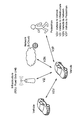
- FIG. 2 is an explanatory diagram for explaining the overall image of V2X communication.
- V2X communication may involve a mobile body, a pedestrian, an RSU, an E-UTRAN (Evolved Universal Terrestrial Radio Access) (that is, a base station of a cellular network), a core network, and a cloud server.
- the cloud server has a V2X application server.
- the core network controls V2X communication.
- the base station performs Uu link communication with a mobile unit, while supporting resource management and communication parameter control for direct communication such as V2V communication and V2P communication.
- RSUs are classified into base station type RSUs and UE type RSUs.
- the RSU provides V2X applications and supports data relays.
- V2X communication a communication system that mainly uses 802.11p-based DSRC (Dedicated Short Range Communication) has been studied so far.
- V2X communication studies are being conducted on a communication system using a cellular phone communication standard such as LTE (Long Term Evolution).
- LTE-based V2X communication exchange of basic safety messages and the like is supported.
- NR V2X communication using 5G technology NR: New Radio
- 5G technology NR: New Radio
- the present technology can also be applied to V2X communication using other communication standards.
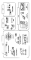
- FIG. 3 is an explanatory diagram for explaining a use case of V2X communication.
- use cases of V2V communication include a forward vehicle approach warning, intersection collision prevention, emergency vehicle warning, platooning, overtaking stop warning, and road construction warning.
- Examples of use cases for V2I communication include provision of road safety information, traffic signal cooperation, and parking lot assistance billing.
- As a use case of V2P communication there is a traffic weak warning.
- Use cases for V2N communication include dynamic map sharing, remote driving, in-car entertainment, and the like.
- NR V2X communication supports new use cases that require high reliability, low latency, high-speed communication, and high capacity that could not be supported by LTE-based V2X.
- the provision of the dynamic map shown, remote driving, and the like are examples.
- Other examples include sensor data sharing in which sensor data is exchanged between vehicles or road vehicles, and platooning use cases for platooning.
- These NR V2X communication use cases and requirements are described in 3GPP TR22.886. As an example, the use case of NR V2X communication will be described below.
- This use case is a use case of platooning in which a plurality of vehicles form a platoon and travel in the same direction. Information for controlling the platooning is exchanged between the vehicle leading the platooning and the other vehicles. By exchanging this information, it becomes possible to further reduce the inter-vehicle distance of the platooning.
- This use case is a use case in which sensor-related information (raw data before data processing or processed data) is exchanged between vehicles. Sensor information is collected through local sensors, surrounding vehicles, RSUs, live video images between pedestrians, V2X application servers, and the like. By exchanging such information, the vehicle can obtain information that cannot be obtained from its own sensor information, and can recognize / recognize a wider range of environments. Since a lot of information can be exchanged, a high data rate is required for communication.
- This use case is a use case of semi-automatic driving or fully automatic driving.
- the RSU shares the recognition / recognition information obtained from its own sensors to the surrounding vehicles, so that each vehicle can adjust the track and operation of the own vehicle while synchronizing and coordinating with other vehicles. it can.
- Each vehicle can share driving intentions and intentions with surrounding vehicles.
- This use case is a use case in which a remote operator or a V2X application controls a vehicle remotely. Remote control is used instead of people who cannot drive or in hazardous areas. Cloud computing-based maneuvers can be used for public transportation where the route or road to be traveled is determined to some extent. High reliability and low transmission delay are required for communication.
- NR V2X is considering further enhancement of the physical layer from LTE V2X.
- the target wireless interface is a Uu interface and a PC5 interface.
- V2X Operation Scenario An example of the V2X communication operation scenario will be described below.
- V2N communication only DL / UL communication between the base station and the terminal device is simple.
- V2V communication various communication paths are conceivable.
- an example of an operation scenario of V2V communication will be described with reference to FIGS.
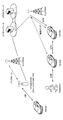
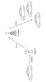
- FIG. 4 is an explanatory diagram for explaining a first scenario of V2V communication.
- mobile objects such as vehicles directly perform V2V communication.
- the communication link in this case is also referred to as SL (ie, PC5).
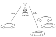
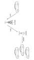
- FIG. 5 is an explanatory diagram for explaining a second scenario of V2V communication.
- mobile bodies such as vehicles perform V2V communication indirectly via E-UTRAN (Evolved Universal Terrestrial Radio Access), that is, via a base station.
- E-UTRAN Evolved Universal Terrestrial Radio Access
- the communication link from the transmission side to the base station is also referred to as Uu UL, and the communication link from the base station to the reception side is also referred to as Uu DL.
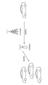
- FIG. 6 is an explanatory diagram for explaining a third scenario of V2V communication.
- a mobile body such as a vehicle transmits a signal to other mobile bodies via the RSU or RSU type UE and the E-UTRAN in order.
- Communication links between the devices are SL (that is, PC5), Uu UL, and Uu DL in this order.
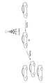
- FIG. 7 is an explanatory diagram for explaining a fourth scenario of V2V communication.
- a mobile body such as a vehicle transmits a signal to other mobile bodies via the E-UTRAN and the RSU or RSU type UE in order.
- Communication links between the devices are Uu UL, Uu DL, and SL (that is, PC5) in this order.
- FIG. 8 is an explanatory diagram for explaining a fifth scenario of V2V communication.
- mobile objects such as vehicles perform V2V communication indirectly via an RSU or RSU type UE.
- the communication link between the mobile and the RSU or RSU type UE is SL (ie PC5).
- FIG. 9 is an explanatory diagram for explaining a sixth scenario of V2V communication.
- mobile objects such as vehicles perform V2V communication indirectly via the UE.
- the communication link between the mobile and the UE is SL (ie PC5).
- Each scenario described above becomes a scenario of V2P communication when one of the moving objects is changed to a pedestrian.
- each scenario becomes a scenario of V2I communication or V2N communication when one of the mobile objects is changed to an infrastructure or a network.
- the use of single antenna transmission or transmission diversity is basically performed on the side link.
- MIMO and beam forming using a plurality of antennas between transmission and reception have not been performed.
- a beamforming technique is used for the side link, it is desirable to consider interference with a base station and peripheral terminals.
- the present disclosure proposes a mechanism for performing communication in consideration of interference given to a base station and peripheral terminals in side link communication using a transmission beam.
- FIG. 10 is an explanatory diagram illustrating an example of a configuration of a system according to an embodiment of the present disclosure.
- the system 1 according to the present embodiment includes a base station 100 and a plurality of terminal devices 200 (200A to 200D).
- the base station 100 is a cellular base station that provides a cellular communication service to the terminal device 200 located in the cell 11.
- the base station 100 controls V2X communication by the terminal device 200 located in the cell 11. For example, the base station 100 allocates a resource pool for V2X communication to the terminal device 200. Further, the base station 100 supports transmission parameter control by the terminal device 200.
- Base station 100 may be a base station type RSU.
- the terminal device 200 is a communication device such as a moving body such as a vehicle, a pedestrian, or a UE type RSU.
- the terminal device 200 can perform communication using any communication method classified as V2X communication, and performs communication based on control by the base station 100.
- the terminal device 200A and the terminal device 200B, and the terminal device 200C and the terminal device 200D can perform side link communication, respectively.
- the terminal device 200 may perform communication using a transmission beam (also referred to as beam forming communication) on the side link.
- the terminal device 200 can perform uplink communication and / or downlink communication with the base station 100.
- FIG. 11 is a block diagram illustrating an example of a logical configuration of the base station 100 according to the present embodiment.
- the base station 100 according to the present embodiment includes an antenna unit 110, a wireless communication unit 120, a network communication unit 130, a storage unit 140, and a control unit 150.
- Antenna unit 110 The antenna unit 110 radiates the signal output from the wireless communication unit 120 to space as a radio wave. Further, the antenna unit 110 converts radio waves in space into a signal and outputs the signal to the wireless communication unit 120.
- the wireless communication unit 120 transmits and receives signals.
- the radio communication unit 120 receives an uplink signal from the terminal device 200 and transmits a downlink signal to the terminal device 200.
- the network communication unit 130 transmits and receives information.
- the network communication unit 130 transmits information to other nodes and receives information from other nodes.
- the other nodes include other base stations 100 and core network nodes.
- Storage unit 140 The storage unit 140 temporarily or permanently stores a program for operating the base station 100 and various data.
- Control unit 150 provides various functions of the base station 100.
- the control unit 150 includes a measurement report unit 151 and a communication control unit 152.
- the measurement report unit 151 measures signals received from other devices and reports information based on the measurement results. For example, the measurement report unit 151 measures an uplink signal transmitted using a transmission beam from the terminal device 200, and reports information based on the measurement result to the transmission source terminal device 200. In addition, the measurement report unit 151 measures the amount of interference caused by the side link signal transmitted using the transmission beam from the terminal device 200 and reports information based on the measurement result to the terminal device 200 that is the transmission source.
- the communication control unit 152 controls communication performed by the terminal device 200 in the cell. For example, the communication control unit 152 controls the transmission parameters of the terminal device 200, such as assigning a resource pool or performing transmission power control. In addition, the communication control unit 152 relays information exchange between the terminal devices 200.
- control unit 150 may further include other components other than these components. That is, the control unit 150 can perform operations other than the operations of these components.
- FIG. 12 is a block diagram illustrating an example of a logical configuration of the terminal device 200 according to the present embodiment.
- the terminal device 200 according to the present embodiment includes an antenna unit 210, a wireless communication unit 220, a storage unit 230, and a control unit 240.
- Antenna unit 210 The antenna unit 210 radiates the signal output from the wireless communication unit 220 to the space as a radio wave. Further, the antenna unit 210 converts a radio wave in the space into a signal and outputs the signal to the wireless communication unit 220.
- the wireless communication unit 220 transmits and receives signals.
- the radio communication unit 220 receives a downlink signal from the base station 100 and transmits an uplink signal to the base station 100.
- the wireless communication unit 220 transmits / receives a side link signal to / from another terminal device 200.
- Storage unit 230 The storage unit 230 temporarily or permanently stores a program for operating the terminal device 200 and various data.
- Control unit 240 provides various functions of the terminal device 200.
- the control unit 240 includes an acquisition unit 241, a parameter determination unit 242, a transmission processing unit 243, and a measurement report unit 244.
- the acquisition unit 241, the parameter determination unit 242, and the transmission processing unit 243 operate mainly when the terminal device 200 performs transmission using a transmission beam.
- the measurement report unit 244 mainly operates when the terminal device 200 is an interference protection target.
- the acquisition unit 241 has a function of acquiring information for determining transmission parameters.
- the acquisition unit 241 acquires information (corresponding to the first information) related to allocation of resource pools that can be used by a plurality of terminal devices 200 using a communication method classified as V2X communication. This information is also referred to as resource pool allocation information below.
- the resource pool allocation information is included in the system information (MIB (Master Information Block) or SIB (System Information Block)) and is notified from the base station 100, for example.
- MIB Master Information Block
- SIB System Information Block
- a resource used for side link communication (hereinafter also referred to as side link resource) and a resource used for uplink communication (hereinafter also referred to as uplink resource) are set in the resource pool.
- the resource pool allocation information may also include setting information for side link resources and uplink resources.
- the acquisition unit 241 includes information related to transmission power (corresponding to second information) associated with beam IDs of a single or a plurality of transmission beams used by the terminal device 200 in communication using a communication method classified as V2X communication. ) To get.
- This information is also referred to as transmission power related information below.
- the transmission power related information may be acquired from the interference protection target or may be acquired by the terminal device 200 itself.
- the interference protection target in the transmission power related information is the terminal device 200 other than the base station 100 or the terminal device 200 of the transmission destination.
- the acquisition unit 241 acquires information (corresponding to third information) determined based on the influence of the transmission beam of the terminal device 200 on the interference protection target.
- this information is also referred to as first interference related information.
- the first interference related information is acquired from the interference protection target.
- the interference protection target in the first interference related information is the terminal device 200 other than the base station 100 or the transmission destination terminal device 200.
- the acquisition unit 241 acquires information (corresponding to fourth information) determined based on the influence of the transmission beam of the other terminal device 200 in the interference protection target.
- this information is also referred to as second interference related information.
- the second interference related information is acquired from the interference protection target.
- the interference protection target in the second interference related information is the terminal device 200 of the communication partner of the terminal device 200, and the interference source is the terminal device 200 other than the communication partner of the terminal device 200.
- the transmission power related information, the first and second interference related information may be included in RRC (Radio Resource Information) signaling, system information or DCI (Downlink Control information), and notified from the base station 100. Further, the transmission power related information and the first and second interference related information can be notified from the other terminal device 200 through the side link.
- RRC Radio Resource Information
- DCI Downlink Control information
- the parameter determination unit 242 determines a parameter related to the transmission beam (hereinafter also referred to as a transmission parameter) based on the information acquired by the acquisition unit 241. Specifically, the parameter determination unit 242 determines transmission parameters based on transmission power related information, first interference related information and / or second interference related information in addition to resource pool allocation information. In that case, the parameter determination part 242 can determine a transmission parameter so that the interference in interference protection object may be suppressed. For example, the parameter determination unit 242 determines a parameter related to at least one of the following. ⁇ Transmission power control ⁇ Implementation or stop of beamforming ⁇ Selection or change of transmission beam to be used ⁇ Selection or change of resource to be used ⁇ Selection or change of resource pool to be used
- the parameter determination unit 242 determines parameters of communication using the transmission beam in the side link based on transmission power related information that is information regarding transmission power corresponding to the transmission beam used by the terminal device 200. As a result, even when the terminal device 200 uses the beamforming technique for side link communication, it is possible to suppress interference that the transmission beam of the terminal device 200 gives to the interference protection target. Such determination of transmission parameters will be described later in detail as the first interference suppression processing.
- the parameter determination unit 242 determines communication parameters using the transmission beam in the side link based on the first interference related information determined based on the influence of the transmission beam used by the terminal device 200 on the interference protection target. To do. As a result, even when the terminal device 200 uses the beamforming technique for side link communication, it is possible to suppress interference that the transmission beam of the terminal device 200 gives to the interference protection target. Such determination of transmission parameters will be described in detail later as the second to fifth interference suppression processes.
- the parameter determination unit 242 sets communication parameters using the transmission beam in the side link based on the second interference related information determined based on the influence of the transmission beam used by the other terminal device 200 on the interference protection target. To decide. Thereby, even when the other terminal device 200 uses the beam forming technique for the side link communication, the communication partner of the terminal device 200 receives from the other terminal device 200 by controlling the transmission parameter used by the terminal device 200. It becomes possible to avoid interference. Such determination of transmission parameters will be described in detail later as a sixth interference suppression process.
- the transmission processing unit 243 performs packet transmission processing using a communication method classified as V2X communication based on the determined transmission parameter. For example, the transmission processing unit 243 performs side link communication with another terminal device 200, or performs uplink communication or downlink communication with the base station 100 for V2X communication via the base station 100. In particular, the transmission processing unit 243 transmits a signal using a transmission beam in side link communication and uplink communication.
- the measurement report unit 244 measures signals received from other devices and reports information based on the measurement results. For example, the measurement report unit 244 measures a side link signal transmitted to itself using a transmission beam from another terminal apparatus 200 and reports information based on the measurement result to the terminal apparatus 200 that is the transmission source. In addition, the measurement report unit 244 measures the amount of interference caused by the side link signal addressed to other than itself transmitted using the transmission beam from the other terminal device 200, and transmits information based on the measurement result to the terminal device of the transmission source Report to 200 mag.
- control unit 150 may further include other components other than these components. That is, the control unit 150 can perform operations other than the operations of these components.
- the transmitting-side terminal device 200 is also referred to as a transmitting terminal 200
- the receiving-side terminal device 200 is also referred to as a receiving terminal 200.
- the terminal device 200 when it is not necessary to distinguish between the transmission terminal 200 and the reception terminal 200, they are collectively referred to as the terminal device 200.
- Interference suppression control in side link communication In typical side link communication, a part of radio resources (frequency time resources) for uplink communication is set as a resource pool for side link communication. The terminal device 200 can perform uplink communication or side link communication using any resource in the resource pool.
- the side link resource is orthogonal to the uplink resource in terms of time and / or frequency.
- IBE In-Band Emission
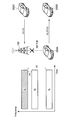
- FIG. 13 is an explanatory diagram for explaining a typical interference suppression process performed in the side link communication.
- the side link transmission from the transmission terminal 200A to the reception terminal 200B interferes with the uplink transmission from the terminal device 200C to the base station 100.
- the left side of FIG. 13 shows an example of resources used for communication, and the right side of FIG. 13 shows the positional relationship of each device that communicates.
- the transmission terminal 200A is located closer to the base station 100 than the terminal device 200C. Therefore, in the base station 100, the reception power of the side link signal from the transmission terminal 200A is larger than the uplink signal from the terminal device 200C.
- the resources used in the side link signal from the transmitting terminal 200A and the uplink signal from the terminal device 200C are orthogonal in the frequency direction. However, in base station 100, the radiation component of the side link signal from transmitting terminal 200A overlaps with the uplink signal from terminal apparatus 200C, and IBE interference occurs.
- a technique for controlling transmission power using a path loss for example, RSRP
- transmission power control is performed on the transmission terminal 200A close to the base station 100, and the amount of interference with the base station 100 is suppressed.
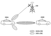
- FIG. 14 is an explanatory diagram for explaining an example of interference with the base station 100 when beamforming is performed in the side link.
- FIG. 14 shows a state in which side link transmission using a transmission beam from transmitting terminal 200A to receiving terminal 200B causes interference to base station 100.
- the transmission terminal 200A transmits a side link signal with the main lobe (desired component) of the transmission beam directed to the reception terminal 200B, the side lobe (interference component) of the transmission beam is directed to the base station 100, and unexpected interference occurs. May occur.
- a mechanism for interference suppression control in consideration of gain due to beamforming in side link communication is provided. According to the interference suppression process described below, even when the transmission terminal 200 transmits a side link signal using a transmission beam, it is possible to ensure that the amount of interference with the base station 100 is below a predetermined amount. is there.
- First interference suppression process In the first interference suppression process, transmission power control based on a gain obtained by beam forming of the transmission terminal 200 is performed. In this processing, the interference protection target is the base station 100.
- P MAX is the maximum transmission power for the side link of the transmission terminal 200.
- ⁇ is a component that increases in proportion to the transmission bandwidth of the side link.
- ⁇ is a component corresponding to the received power in the base station 100.
- ⁇ is a path loss component between the base station 100 and the transmission terminal 200.
- ⁇ is a gain component obtained by beam forming.
- ⁇ is a component corresponding to the distance in the frequency direction between used resources in the resource pool.
- Whether or not to perform transmission power control may be determined depending on whether or not the frequency of the side link communication overlaps with a frequency band (for example, uplink frequency band) assigned to the base station 100.
- a frequency band for example, uplink frequency band
- the above formula (1) is used when the frequency of the side link communication overlaps with a part of the frequency band assigned to the base station 100, and when the frequency does not overlap, the maximum transmission for the side link of the transmission terminal 200 is used.
- the power P MAX [dBm] may be used.
- the transmission power in the conventional side link communication has been determined using ⁇ , ⁇ and ⁇ .
- ⁇ is calculated from the transmission power of the reference signal from the base station 100 and the reception power (for example, RSRP) at the transmission terminal 200.
- ⁇ decreases as the distance between the base station 100 and the transmission terminal 200 increases, and increases as it approaches.
- transmission power is determined as follows:
- ⁇ ⁇ is information related to the gain for the interference protection target (ie, the base station 100) obtained by the transmission beam.
- ⁇ corresponds to the transmission power related information described above.
- ⁇ may be calculated based on a gain value for an interference protection target (ie, base station 100) obtained by a transmission beam formed by transmission terminal 200. Good.
- ⁇ may be determined based on the result of beamforming between the transmitting terminal 200 and the receiving terminal 200. That is, ⁇ may be determined based on a transmission beam used by the transmission terminal 200 for transmission to the reception terminal 200.
- the transmitting terminal 200 performs beamforming for side link transmission to the receiving terminal 200, and uses the obtained gain ⁇ for transmission power control. For example, the maximum gain value set for the side link transmission beam is used as the maximum value of ⁇ .
- the transmission beam used by the transmission terminal 200 in the side link is specified using the beam ID.
- the process for determining ⁇ based on the transmission beam used by the transmission terminal 200 in the side link corresponds to option # 2 of the sequence shown in FIG.
- ⁇ may be determined based on the result of beamforming between the transmitting terminal 200 and the base station 100. That is, ⁇ may be determined based on a transmission beam used by the transmission terminal 200 for transmission to the base station 100.
- the transmission terminal 200 performs beamforming for Uu uplink transmission to the base station 100, and uses the obtained gain ⁇ for transmission power control. For example, the maximum gain value set for the Uu uplink transmission beam is used as the maximum value of ⁇ .
- the transmission beam used by the transmission terminal 200 in the Uu uplink is specified using the beam ID.
- the process in which ⁇ is determined based on the transmission beam used by the transmitting terminal 200 in the Uu uplink corresponds to option # 1 of the sequence shown in FIG.
- ⁇ may be an average value of gains of transmission beams used by the transmission terminal 200 during a predetermined time.
- ⁇ is set to an average value of gains of transmission beams transmitted by the transmission terminal 200 in the side link or Uu uplink in a predetermined period.
- ⁇ may be determined based on location information of transmitting terminal 200. Specifically, ⁇ may be determined based on the relative positional relationship between the transmission terminal 200 and the base station 100. For example, ⁇ is determined based on the zone information of the transmission terminal 200 and the zone information of the base station 100.
- the zone information is information indicating which zone is located among a plurality of preset zones (indicating a geographical range).
- ⁇ notification / setting method ⁇ is a parameter ⁇ 1 (corresponding to information on the first gain) peculiar to the transmitting terminal 200 (that is, UE specific) and a cell ⁇ 2 (second cell specific) May be included).
- ⁇ may simply be the sum of ⁇ 1 and ⁇ 2, may be a weighted sum, or may be calculated by any other calculation method.
- ⁇ 1 is set for each transmission terminal 200 by RRC signaling, for example.
- a reference table in which each of the plurality of beam IDs is associated with the value of ⁇ 1 may be individually set, and ⁇ 1 may be determined based on the reference table.
- the transmission terminal 200 refers to a reference table individually set for the transmission terminal 200 and determines ⁇ 1 associated with the beam ID of the transmission beam to be used as ⁇ 1 to be used.
- the base station 100 may directly set ⁇ 1 to be used by the transmission terminal 200. Further, the base station 100 may set the maximum value of ⁇ 1 in the transmission terminal 200.
- ⁇ 2 is set in the transmission terminal 200 by, for example, system information (especially SIB).
- SIB system information
- ⁇ 2 may be determined based on the distance in the frequency direction between the side link resource and the uplink resource in the resource pool. This is because the interference (IBE) decreases as the distance in the frequency direction between the side link resource and the uplink resource increases, and the interference increases as the distance becomes shorter.
- a reference table may be set in which each of the plurality of zone information is associated with the value of ⁇ 2.
- FIG. 15 is an explanatory diagram for explaining an example of transmission power control according to the present embodiment.
- FIG. 15 illustrates a state in which side link transmission from the transmission terminal 200A to the reception terminal 200B interferes with uplink transmission from the terminal device 200C to the base station 100.
- the left side of FIG. 15 shows an example of resources used for communication, and the right side of FIG. 15 shows the positional relationship of each device that communicates.
- the transmission terminal 200A sets a small maximum transmission power when using a side link resource whose distance in the frequency direction from the uplink resource is ⁇ 1.
- the transmitting terminal 200A sets the maximum transmission power that is larger than the case of using the side link resource of ⁇ 1.
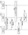
- FIG. 16 is a sequence diagram illustrating an example of a flow of a first interference suppression process executed in the system 1 according to the present embodiment.
- the base station 100, the transmission terminal 200A, and the reception terminal 200B are involved in this sequence.
- base station 100 may be a base station type RSU.
- the base station 100 transmits resource pool allocation information to the transmission terminal 200A and the reception terminal 200B (step S102). Thereafter, either option # 1 or # 2 is implemented.
- the base station 100 and the transmission terminal 200A perform beam forming processing (step S104). Specifically, the transmission terminal 200A transmits an uplink signal to the base station 100 using a transmission beam. Next, the base station 100 calculates the gain obtained by the transmission beam based on the reception result of the uplink signal, and determines ⁇ (step S106). Next, the base station 100 notifies the determined ⁇ to the transmission terminal 200A (step S108).
- the transmitting terminal 200A and the receiving terminal 200B perform beam forming processing (step S110). Specifically, the transmission terminal 200A transmits a side link signal to the reception terminal 200B using a transmission beam. Next, transmitting terminal 200A calculates the gain obtained by the transmission beam and determines ⁇ (step S106).
- the transmitting terminal 200A determines the transmission power of the transmission beam used for transmitting the side link signal based on the notified or determined ⁇ (step S114). Thereafter, the transmitting terminal 200A performs beamforming communication with the receiving terminal 200 using the determined transmission power (step S116).
- the transmission terminal 200 may control the resource used for the side link together with or instead of the transmission power control described above. For example, if the transmission terminal 200 uses the transmission power determined by the transmission power control described above, and determines that the desired quality is not satisfied at the packet transmission destination, the transmission terminal 200 changes the resource used.
- the transmitting terminal 200 may transmit a resource change request to the base station 100 and receive the allocation of the side link resource by DCI again. Moreover, the transmission terminal 200 may perform sensing for resource reselection again by applying a resource reselection trigger to perform resource selection.
- a desired quality may be set as a threshold value, or an arbitrary value may be set as the threshold value.
- the threshold value may be provided from the base station 100 by RRC signaling or SIB.
- the threshold value may be preset (Preconfigure) in the transmission terminal 200 or may be preset (Preconfigure) for each frequency band.
- Second interference suppression process In the second interference suppression process, the interference protection target feeds back to the transmission terminal 200 the influence of the beam forming communication between the transmission terminal 200 and the reception terminal 200, and the transmission terminal 200 controls the transmission parameter based on the feedback.
- the interference protection target is the base station 100.
- Interference report information for side link communication using a transmission beam The base station 100 measures IBE interference caused by side link transmission using a transmission beam by the transmission terminal 200. Base station 100 then feeds back information (hereinafter also referred to as interference report information) based on the measurement result to transmitting terminal 200. The base station 100 may feed back the trigger when the amount of interference exceeds a predetermined threshold.
- the interference report information corresponds to the transmission power related information described above.
- the interference report information is information based on the measurement result in the interference protection target (that is, the base station 100) of the interference caused by the side link communication using the transmission beam performed between the transmission terminal 200 and the reception terminal 200. Including.
- the interference report information includes at least one of the following information. -Information indicating that the specified amount of interference has been exceeded-Information for transmission power control-Request to change the transmission beam to be used-Request to stop beamforming-Request to change resource to be used-Change notification of resource pool
- the information for transmission power control includes, for example, a TPC command.
- the resource change request to be used includes information for requesting change of the resource used in the allocated resource pool.
- the resource pool change notification includes, for example, information indicating that the resource pool allocation is changed or information indicating that the resource pool is reset.
- the base station 100 measures the interference caused by the side link transmission using the transmission beam by the transmission terminal 200, and generates the above information. These pieces of information may be associated with the measured beam ID of the transmission beam.
- the interference report information may further include at least one of the following information. -Time frequency resource in which interference occurs-Measurement result of IBE interference-Location information of transmitting terminal 200-Traveling direction of transmitting terminal 200
- the measurement result of IBE interference may include information indicating the amount of interference, or may include information indicating the amount of interference exceeding the threshold value.
- the transmission terminal 200 may be assigned from the base station 100 resources to be used in the side link. Such an operation mode is also referred to as mode 3 (mode 3). In the case of mode 3, the base station 100 can grasp which terminal device 200 is using which resource, and thus can specify a feedback destination.
- mode 3 mode 3
- the base station 100 can grasp which terminal device 200 is using which resource, and thus can specify a feedback destination.
- the transmitting terminal 200 may itself select a resource to be used for side link communication from the allocated resource pool. Such an operation mode is also referred to as mode 4 (mode 3). In the case of mode 4, it is difficult for the base station 100 to grasp which terminal device 200 is using which resource.
- the terminal device 200 may notify the base station 100 in advance of information indicating whether or not beam forming is performed in the side link and / or capability information indicating whether or not beam forming can be performed. Good.
- the base station 100 may notify the terminal device 200 in advance of permission / non-permission of beamforming in the side link. As a result, the base station 100 can grasp which terminal device 200 is using which resource. Further, the terminal device 200 may notify the base station 100 of the location information in advance.
- the base station 100 feeds back the interference report information to the transmission terminal 200 specified as the feedback destination.
- the feedback destination for example, RRC signaling or DCI may be used.
- the base station 100 may notify all the terminal devices 200 using the resource pool in which the interference occurs to notify the interference report information. Good.
- the base station 100 may notify the resource pool allocation information in association with the interference report information.
- SIB can be used.
- the base station 100 may notify interference report information specific to the resource pool for each resource pool. In this case, for example, RRC signaling or DCI may be used.
- the base station 100 may notify the interference report information to all the terminal devices 200 performing the side link communication.
- SIB or RRC signaling may be used.
- the transmission terminal 200 controls transmission parameters based on the interference report information notified from the base station 100.
- the terminal device 200 controls transmission parameters so that the amount of interference in the base station 100 is equal to or less than a predetermined threshold. Thereby, it is possible to suppress interference given to the base station 100.
- the transmission terminal 200 determines a transmission parameter related to at least one of the following. -Transmit power control-Stop beamforming-Change the transmit beam to use-Change the resource to use-Change the resource pool to use
- the transmission terminal 200 determines to reduce the transmission power.
- the transmission terminal 200 determines the transmission beam to be changed based on the position information of the transmission terminal 200, the reception terminal 200, and the base station 100.
- the transmitting terminal 200 determines the resource to be used or the resource pool to be used so that the distance in the frequency direction from the uplink resource used by the base station 100 is increased. Perform the change process.
- the transmission terminal 200 determines the transmission parameter according to the instruction (that is, adopts it as it is).
- the transmission terminal 200 may accumulate interference report information in a database. And the terminal device 200 may control a transmission parameter (for example, selection of a transmission beam) based on the positional relationship between the transmission terminal 200 and the base station 100 and the accumulated interference report information.
- a transmission parameter for example, selection of a transmission beam
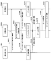
- FIG. 17 is a sequence diagram illustrating an example of the flow of the second interference suppression process executed in the system 1 according to the present embodiment.
- base station 100 the transmission terminal 200A, and the reception terminal 200B are involved in this sequence.
- base station 100 may be a base station type RSU.
- the base station 100 transmits resource pool allocation information to the transmission terminal 200A and the reception terminal 200B (step S202).
- the transmitting terminal 200A notifies the base station 100 that beam forming communication is to be performed (step S204).
- the transmitting terminal 200A and the receiving terminal 200B perform beamforming communication (step S206). Specifically, the transmission terminal 200A transmits a side link signal to the reception terminal 200B using a transmission beam.
- the base station 100 measures the amount of interference received by the beamforming communication in step S206 (step S208).
- the base station 100 transmits the interference report information generated based on the measurement result to the transmission terminal 200A (step S210).
- the transmitting terminal 200A controls transmission parameters based on the fed back interference report information (step S212).
- the transmission terminal 200 performs beam sweeping, and selects a transmission beam based on feedback from the base station 100 with respect to beam sweeping.
- the interference protection target is the base station 100.
- the transmission terminal 200 uses each of a plurality of usable transmission beams to select a transmission resource to be used for beamforming communication, and thereby a measurement signal (for example, a reference signal). Send. Such processing is also referred to as beam sweeping.
- the measurement signal is transmitted in association with the beam ID.
- the measurement signal is transmitted using information indicating the beam ID of the transmission beam or using a resource corresponding to the beam ID of the transmission beam. Accordingly, the receiving side can identify which transmission beam is used for the received measurement signal.
- the beam-swept measurement signal is measured by the receiving side, and information based on the measurement result is fed back to the transmitting terminal 200.
- the information fed back includes information (hereinafter also referred to as measurement report information) based on the measurement result at the reception terminal 200 of the measurement signal beam-swept by the transmission terminal 200.
- the reception terminal 200 measures each of the beam-swept measurement signals, generates measurement report information based on the measurement result, and feeds back the measurement report information to the transmission terminal 200.
- the receiving terminal 200 feeds back a beam ID of a transmission beam that has secured an SINR equal to or greater than a predetermined threshold as measurement report information.
- the information fed back includes information (hereinafter also referred to as interference report information) based on the measurement result in the interference protection target (that is, the base station 100) of the measurement signal beam-swept by the transmission terminal 200.
- the base station 100 measures interference received by each of the measurement signals beam-swept with respect to the receiving terminal 200, generates interference report information based on the measurement result, and feeds back to the transmitting terminal 200. For example, the base station 100 feeds back the beam ID of the transmission beam whose interference amount exceeds a predetermined threshold as the interference report information.
- the interference report information corresponds to the first interference related information described above.
- the transmitting terminal 200 may notify the base station 100 that beam sweeping is to be performed.
- the notification may include time-frequency resource information used for beam sweeping. Thereby, the base station 100 can efficiently perform the measurement of the notified resource and in-band radiation in the vicinity thereof.
- RRC signaling may be used for feedback from the base station 100 to the transmission terminal 200.
- the transmission terminal 200 selects a transmission beam to be used for side link transmission to the reception terminal 200 based on the fed back measurement report information and interference report information. For example, the terminal device 200 can secure an SINR equal to or higher than the predetermined threshold at the receiving terminal 200 indicated by the measurement report information other than a transmission beam whose interference amount at the base station 100 indicated by the interference report information exceeds a predetermined threshold. Select the transmitted beam. Thereby, it is possible to suppress the amount of interference in the interference protection target while securing a desired SINR in the receiving terminal 200.
- FIG. 18 is a sequence diagram illustrating an example of the flow of the third interference suppression process executed in the system 1 according to the present embodiment.
- base station 100 the transmission terminal 200A, and the reception terminal 200B are involved in this sequence.
- base station 100 may be a base station type RSU.
- the base station 100 transmits resource pool allocation information to the transmission terminal 200A and the reception terminal 200B (step S302).
- the transmitting terminal 200A determines to perform beamforming communication (step S304).
- the transmitting terminal 200A notifies each of the receiving terminal 200B and the base station 100 that the beamforming sweeping is to be performed (step S306). At this time, information indicating resources and timing used for beam sweeping is also notified.
- the transmitting terminal 200A performs beam sweeping (step S308).
- the receiving terminal 200B measures each of the beam-swept measurement signals (Step S310), and feeds back the measurement report information to the transmitting terminal 200A (Step S312). For example, the receiving terminal 200B feeds back a beam ID of a transmission beam that exceeds a predetermined SINR.
- the base station 100 measures the amount of interference received from each of the beam-swept measurement signals (step S314), and feeds back the measurement report information to the transmission terminal 200A (step S316). For example, the base station 100 feeds back a beam ID of a transmission beam that exceeds a predetermined interference threshold.
- the transmitting terminal 200A determines the beam ID of the transmission beam used for side link transmission to the receiving terminal 200B based on the fed back measurement report information and interference report information (step S318). Thereafter, the transmitting terminal 200A notifies the determined beam ID to the receiving terminal 200 (step S320), and performs beamforming communication with the receiving terminal 200 using the transmitted beam of the determined beam ID (step S322).
- interference due to the influence of IBE may occur in the terminal devices 200 around the transmission terminal 200. Specifically, when there are a plurality of pairs of the transmission terminal 200 and the reception terminal 200 that perform side link communication, interference due to IBE may occur between neighboring pairs even if resources used between the pairs are different in the time-frequency direction. . In particular, when the transmission terminal 200 performs side link transmission using a transmission beam, it may interfere with many other terminal devices 200 located around the transmission terminal 200. This point will be described with reference to FIG.
- FIG. 19 is an explanatory diagram for explaining an example of interference with peripheral terminal devices 200 occurring in side link communication.
- the transmission terminal 200A performs side link transmission using a transmission beam to the reception terminal 200B, and the transmission terminal 200C performs side link transmission to the reception terminal 200D.
- the transmission terminal 200A transmits a side link signal with the main lobe (desired component) of the transmission beam directed to the reception terminal 200B
- the side lobe (interference component) of the transmission beam is directed to the reception terminal 200D
- unexpected interference May occur.
- the side link resource used by the pair of the transmission terminal 200A and the reception terminal 200B and the side link resource used by the pair of the transmission terminal 200C and the reception terminal 200D are orthogonal in the frequency direction. However, interference due to IBE can occur.
- a mechanism for interference suppression control in consideration of gain due to beamforming in side link communication is provided. According to the interference suppression process described below, even when the transmitting terminal 200 performs beamforming and transmits a side link signal, it is possible to ensure that the amount of interference with the surrounding terminal device 200 is equal to or less than a predetermined amount. Is possible.
- the transmission terminal 200 performs beam sweeping, and selects a transmission beam based on feedback from surrounding terminal devices 200 for beam sweeping.
- the interference protection target is the peripheral terminal device 200 (hereinafter also referred to as the peripheral terminal 200).
- the transmission terminal 200 performs beam sweeping by transmitting a measurement signal (for example, a reference signal) using each of a plurality of usable transmission beams.
- the beam-swept measurement signal is measured by the receiving side, and information based on the measurement result is fed back to the transmitting terminal 200.
- the information fed back includes information (hereinafter also referred to as measurement report information) based on the measurement result at the reception terminal 200 of the measurement signal beam-swept by the transmission terminal 200.
- the reception terminal 200 measures each of the beam-swept measurement signals, generates measurement report information based on the measurement result, and feeds back the measurement report information to the transmission terminal 200.
- the receiving terminal 200 feeds back a beam ID of a transmission beam that has secured an SINR equal to or greater than a predetermined threshold as measurement report information.
- the information fed back includes information (hereinafter also referred to as interference report information) based on the measurement result in the interference protection target (that is, the peripheral terminal 200) of the measurement signal beam-swept by the transmission terminal 200.
- the peripheral terminal 200 measures the interference received by each of the measurement signals beam-swept with respect to the receiving terminal 200, generates interference report information based on the measurement result, and feeds back to the transmitting terminal 200.
- the peripheral terminal 200 feeds back the beam ID of the transmission beam whose interference amount exceeds a predetermined threshold as the interference report information.
- the feedback may be performed directly from the peripheral terminal 200 to the transmitting terminal 200 or may be performed via the base station 100.
- the interference report information corresponds to the first interference related information described above.
- the transmitting terminal 200 may notify (for example, broadcast) to the peripheral terminal 200 that the beam sweeping is to be performed.
- the notification may include time-frequency resource information used for beam sweeping.
- the peripheral terminal 200 can efficiently perform the measurement of the notified resource and in-band radiation in the vicinity thereof.
- the transmission terminal 200 selects a transmission beam to be used for side link transmission to the reception terminal 200 based on the fed back measurement report information and interference report information. For example, the terminal device 200 can secure an SINR equal to or greater than the predetermined threshold at the receiving terminal 200 indicated by the measurement report information other than a transmission beam whose interference amount at the peripheral terminal 200 indicated by the interference report information exceeds a predetermined threshold. Select the transmitted beam. Thereby, it is possible to suppress the amount of interference in the interference protection target while securing a desired SINR in the receiving terminal 200.
- the transmission terminal 200 may select a transmission beam to be used for side link transmission to the reception terminal 200 based on interference report information from the base station 100 for beam sweeping.
- the interference report information from the base station 100 is as described in the third interference suppression process.
- the transmission terminal 200 may set the upper limit value of the transmission power based on the interference report information from the base station 100 for beam sweeping.
- FIG. 20 is a sequence diagram illustrating an example of the flow of a fourth interference suppression process executed in the system 1 according to the present embodiment.
- base station 100 the transmission terminal 200A, the reception terminal 200B, and the peripheral terminal 200C are involved in this sequence.
- base station 100 may be a base station type RSU.
- the base station 100 transmits resource pool allocation information to the transmission terminal 200A, the reception terminal 200B, and the peripheral terminal 200C (step S402).
- the transmitting terminal 200A notifies each of the receiving terminal 200B and the peripheral terminal 200C that beam sweeping is to be performed (step S404). At this time, information indicating resources and timing used for beam sweeping is also notified.
- the transmitting terminal 200A performs beam sweeping (step S406).
- the receiving terminal 200B measures each of the beam-swept measurement signals (Step S408), and feeds back the measurement report information to the transmitting terminal 200A (Step S410). For example, the receiving terminal 200B feeds back a beam ID of a transmission beam that exceeds a predetermined SINR.
- peripheral terminal 200C measures the amount of interference received from each of the beam-swept measurement signals (step S412), and feeds back interference report information to transmitting terminal 200A (step S414). For example, the peripheral terminal 200C feeds back a beam ID of a transmission beam that exceeds a predetermined interference threshold.
- the transmission terminal 200A determines the beam ID of the transmission beam used for side link transmission to the reception terminal 200B based on the fed back measurement report information and interference report information (step S416). Thereafter, the transmitting terminal 200A notifies the receiving terminal 200 of the determined beam ID (step S418), and performs beamforming communication with the receiving terminal 200 using the transmitting beam of the determined beam ID (step S420).
- the interference protection target feeds back to the transmission terminal 200 the influence of the beam forming communication between the transmission terminal 200 and the reception terminal 200, and the transmission terminal 200 controls the transmission parameter based on the feedback.
- the interference protection target is the peripheral terminal 200.
- Interference report information for side link communication using a transmission beam The peripheral terminal 200 measures IBE interference caused by side link transmission using a transmission beam by the transmission terminal 200. Then, the peripheral terminal 200 feeds back information (hereinafter also referred to as interference report information) based on the measurement result to the transmitting terminal 200. Peripheral terminal 200 may trigger feedback that the amount of interference exceeds a predetermined threshold.
- the interference report information corresponds to the first interference related information described above.
- the interference report information is information based on the measurement result in the interference protection target (that is, the peripheral terminal 200) of the interference caused by the side link communication using the transmission beam performed between the transmission terminal 200 and the reception terminal 200. is there.
- the interference report information includes at least one of the following information. -Information indicating that the specified interference amount has been exceeded-Information for transmission power control-Request to change the transmission beam to be used-Request to stop beamforming-Request to change resource to be used
- the information for transmission power control includes, for example, information requesting to reduce transmission power.
- the resource change request to be used includes information for requesting change of the resource used in the allocated resource pool.
- Peripheral terminal 200 measures the interference caused by side link transmission using the transmission beam by transmission terminal 200 and generates the above information. These pieces of information may be associated with the measured beam ID of the transmission beam.
- the interference report information may further include at least one of the following information.
- Time frequency resources used by the peripheral terminal 200 Measurement result of IBE interference Position information of the peripheral terminal 200 Travel direction of the peripheral terminal 200 Position information of the transmission terminal 200 Travel direction of the transmission terminal 200
- the measurement result of IBE interference may include information indicating the amount of interference, or may include information indicating the amount of interference exceeding the threshold value.
- the peripheral terminal 200 may directly feed back the interference report information to the transmitting terminal 200.
- the peripheral terminal 200 may broadcast the interference report information to the periphery, or may unicast to the transmitting terminal 200.
- SCI Servicelink Control Information
- SSCH Servicelink Shared Channel
- the peripheral terminal 200 may feed back the interference report information via the base station 100. In that case, the peripheral terminal 200 notifies the base station 100 of the identification information of the transmission terminal 200 that is the interference source, the information indicating the resource in which the interference has occurred, and the beam ID of the transmission beam that has received the interference together with the interference report information. .
- the identification of the feedback destination and the feedback method by the base station 100 are the same as in the second interference suppression process.
- the transmission terminal 200 controls transmission parameters based on the interference report information fed back from the peripheral terminal 200.
- the transmission terminal 200 controls transmission parameters so that the amount of interference in the peripheral terminal 200 is equal to or less than a predetermined threshold. Thereby, it is possible to suppress interference given to the peripheral terminal 200.
- the transmission terminal 200 performs transmission parameters related to at least one of the following. -Transmit power control-Stop beamforming-Change the transmit beam to use-Change the resource to use-Change the resource pool to use
- the transmission terminal 200 determines to reduce the transmission power.
- the transmission terminal 200 determines the transmission beam to be changed based on the position information of the transmission terminal 200, the reception terminal 200, and the peripheral terminal 200.
- the transmission terminal 200 determines the resource to be used or the resource pool to be used so that the distance in the frequency direction from the resource used by the peripheral terminal 200 is increased. Perform the change process.
- the transmission terminal 200 determines the transmission parameter according to the instruction (that is, adopts it as it is).
- the transmission terminal 200 may accumulate interference report information in a database. And the terminal device 200 may control a transmission parameter (for example, selection of a transmission beam) based on the positional relationship between the transmission terminal 200 and the peripheral terminal 200 and the accumulated interference report information.
- a transmission parameter for example, selection of a transmission beam
- FIG. 21 is a sequence diagram illustrating an example of a flow of fifth interference suppression processing executed in the system 1 according to the present embodiment.
- the base station 100, the transmitting terminal 200A, the receiving terminal 200B, and the peripheral terminal 200C are involved in this sequence.
- base station 100 may be a base station type RSU.
- the base station 100 transmits resource pool allocation information to the transmission terminal 200A, the reception terminal 200B, and the peripheral terminal 200C (step S502).
- the transmitting terminal 200A notifies the peripheral terminal 200C that beam forming communication is to be performed (step S504).
- the transmitting terminal 200A and the receiving terminal 200B perform beamforming communication (step S506).
- the transmission terminal 200A transmits a side link signal to the reception terminal 200B using a transmission beam.
- the peripheral terminal 200C measures the amount of interference received by the beamforming communication in step S506 (step S508). Thereafter, either option # 1 or # 2 is implemented.
- the peripheral terminal 200C transmits the interference report information generated based on the measurement result to the transmission terminal 200A (step S510). Then, the transmitting terminal 200A controls the transmission parameter based on the fed back interference report information (step S512).
- the peripheral terminal 200C transmits information based on the measurement result to the base station 100 (step S514).
- the base station 100 specifies a feedback destination of the interference report information acquired from the peripheral terminal 200C and determines a feedback method (step S516).
- the base station 100 transmits the interference report information acquired from the peripheral terminal 200C to the transmission terminal 200A (step S518).
- the transmitting terminal 200A controls transmission parameters based on the fed back interference report information (step S520).
- the peripheral terminal 200 on the transmission side is also referred to as the peripheral transmission terminal 200
- the peripheral terminal 200 on the reception side is also referred to as the peripheral reception terminal 200.
- the transmission parameters used by the peripheral transmission terminal 200 for the side link transmission based on the influence received by the peripheral reception terminal 200 by the side link transmission using the transmission beam from the transmission terminal 200 to the reception terminal 200 To control.
- the interference protection target is the peripheral reception terminal 200
- the interference source is the transmission terminal 200.
- Interference report information for side link communication using a transmission beam The peripheral reception terminal 200 measures IBE interference caused by side link transmission using a transmission beam by the transmission terminal 200. Then, the peripheral terminal 200 feeds back information (hereinafter also referred to as interference report information) based on the measurement result to the peripheral transmission terminal 200. Peripheral receiving terminal 200 may feed back the trigger when the amount of interference exceeds a predetermined threshold.
- the interference report information corresponds to the above-described second interference related information.
- the interference report information is an interference protection target (that is, a peripheral receiving terminal) of interference caused by side link communication using a transmission beam performed between other terminal apparatuses 200 (that is, between the transmitting terminal 200 and the receiving terminal 200). 200) based on the measurement result.
- the interference report information includes at least one of the following information. -Information indicating that the specified interference amount has been exceeded-Information for transmission power control-Request to change the transmission beam to be used-Request to change the resource to be used
- the information for transmission power control includes, for example, information requesting to increase transmission power.
- the resource change request to be used includes information for requesting change of the resource used in the allocated resource pool.
- the peripheral reception terminal 200 measures interference caused by side link transmission using the transmission beam by the transmission terminal 200 and generates the above information. These pieces of information may be associated with the measured beam ID of the transmission beam.
- the interference report information may further include at least one of the following information. -Time frequency resource in which interference occurs-Measurement result of IBE interference-Location information of peripheral receiving terminal 200 and transmitting terminal 200-Traveling direction of peripheral receiving terminal 200 and transmitting terminal 200
- the measurement result of IBE interference may include information indicating the amount of interference, or may include information indicating the amount of interference exceeding the threshold value.
- the peripheral transmission terminal 200 controls transmission parameters based on the interference report information fed back from the peripheral reception terminal 200.
- Peripheral transmission terminal 200 controls transmission parameters so that SINR in peripheral reception terminal 200 is improved. As a result, it is possible to suppress the relative influence of interference received by the peripheral receiving terminal 200 compared to the desired component.
- the peripheral transmission terminal 200 performs at least one of the following. ⁇ Transmission power control ⁇ Beam forming ⁇ Change of used transmit beam ⁇ Change of used resource ⁇ Change of used resource pool
- the peripheral transmission terminal 200 determines to increase the transmission power.
- the peripheral transmission terminal 200 determines the transmission beam to be changed based on the position information of the transmission terminal 200, the reception terminal 200, and the peripheral reception terminal 200.
- the peripheral transmission terminal 200 uses the resource to be used or the resource pool to be used so that the distance in the frequency direction from the resource used by the transmission terminal 200 is increased. Process to change.
- the peripheral transmission terminal 200 determines the transmission parameter (that is, adopts it as it is) according to the instruction.
- FIG. 22 is a sequence diagram illustrating an example of a flow of sixth interference suppression processing executed in the system 1 according to the present embodiment.
- the base station 100, the transmission terminal 200A, the reception terminal 200B, the peripheral transmission terminal 200C, and the peripheral reception terminal 200D are involved in this sequence.
- base station 100 may be a base station type RSU.
- the base station 100 transmits resource pool allocation information to the transmission terminal 200A, the reception terminal 200B, the peripheral transmission terminal 200C, and the peripheral reception terminal 200D (step S602).
- the transmission terminal 200 and the reception terminal 200 perform beamforming communication (step S604), and the peripheral transmission terminal 200C and the peripheral reception terminal 200D perform communication (may be beamforming communication) (step S606).
- the peripheral reception terminal 200D measures the amount of interference received by the beamforming communication in step S604 (step S608).
- the peripheral receiving terminal 200D transmits the interference report information generated based on the measurement result to the peripheral transmitting terminal 200C (step S610).
- peripheral transmission terminal 200C controls transmission parameters for improving SINR based on the fed back interference report information (step S612), and communicates with peripheral reception terminal 200D using the new transmission parameters (step S612). S614).
- the base station 100 may be realized as any type of eNB (evolved Node B) such as a macro eNB or a small eNB.
- the small eNB may be an eNB that covers a cell smaller than a macro cell, such as a pico eNB, a micro eNB, or a home (femto) eNB.
- the base station 100 may be realized as another type of base station such as a NodeB or a BTS (Base Transceiver Station).
- the base station 100 may include a main body (also referred to as a base station apparatus) that controls wireless communication, and one or more RRHs (Remote Radio Heads) that are arranged at locations different from the main body. Further, various types of terminals described later may operate as the base station 100 by temporarily or semi-permanently executing the base station function.
- the terminal device 200 is a smartphone, a tablet PC (Personal Computer), a notebook PC, a portable game terminal, a mobile terminal such as a portable / dongle type mobile router or a digital camera, or an in-vehicle terminal such as a car navigation device. It may be realized as.
- the terminal device 200 may be realized as a terminal (also referred to as an MTC (Machine Type Communication) terminal) that performs M2M (Machine To Machine) communication.
- the terminal device 200 may be a wireless communication module (for example, an integrated circuit module configured by one die) mounted on these terminals.
- FIG. 23 is a block diagram illustrating a first example of a schematic configuration of an eNB to which the technology according to the present disclosure may be applied.
- the eNB 800 includes one or more antennas 810 and a base station device 820. Each antenna 810 and the base station apparatus 820 can be connected to each other via an RF cable.
- Each of the antennas 810 has a single or a plurality of antenna elements (for example, a plurality of antenna elements constituting a MIMO antenna), and is used for transmission and reception of radio signals by the base station apparatus 820.
- the eNB 800 includes a plurality of antennas 810 as illustrated in FIG. 23, and the plurality of antennas 810 may respectively correspond to a plurality of frequency bands used by the eNB 800, for example. 23 shows an example in which the eNB 800 includes a plurality of antennas 810, the eNB 800 may include a single antenna 810.
- the base station apparatus 820 includes a controller 821, a memory 822, a network interface 823, and a wireless communication interface 825.
- the controller 821 may be a CPU or a DSP, for example, and operates various functions of the upper layer of the base station apparatus 820. For example, the controller 821 generates a data packet from the data in the signal processed by the wireless communication interface 825, and transfers the generated packet via the network interface 823. The controller 821 may generate a bundled packet by bundling data from a plurality of baseband processors, and may transfer the generated bundled packet. In addition, the controller 821 is a logic that executes control such as radio resource control, radio bearer control, mobility management, inflow control, or scheduling. May have a typical function. Moreover, the said control may be performed in cooperation with a surrounding eNB or a core network node.
- the memory 822 includes RAM and ROM, and stores programs executed by the controller 821 and various control data (for example, terminal list, transmission power data, scheduling data, and the like).
- the network interface 823 is a communication interface for connecting the base station device 820 to the core network 824.
- the controller 821 may communicate with the core network node or other eNB via the network interface 823.
- the eNB 800 and the core network node or another eNB may be connected to each other by a logical interface (for example, an S1 interface or an X2 interface).
- the network interface 823 may be a wired communication interface or a wireless communication interface for wireless backhaul.
- the network interface 823 may use a frequency band higher than the frequency band used by the wireless communication interface 825 for wireless communication.
- the wireless communication interface 825 supports any cellular communication scheme such as LTE (Long Term Evolution) or LTE-Advanced, and provides a wireless connection to terminals located in the cell of the eNB 800 via the antenna 810.
- the wireless communication interface 825 may typically include a baseband (BB) processor 826, an RF circuit 827, and the like.
- the BB processor 826 may perform, for example, encoding / decoding, modulation / demodulation, and multiplexing / demultiplexing, and each layer (for example, L1, MAC (Medium Access Control), RLC (Radio Link Control), and PDCP).
- Various signal processing of Packet Data Convergence Protocol
- Packet Data Convergence Protocol is executed.
- the BB processor 826 may have some or all of the logical functions described above instead of the controller 821.
- the BB processor 826 may be a module that includes a memory that stores a communication control program, a processor that executes the program, and related circuits. The function of the BB processor 826 may be changed by updating the program. Good.
- the module may be a card or a blade inserted into a slot of the base station apparatus 820, or a chip mounted on the card or the blade.
- the RF circuit 827 may include a mixer, a filter, an amplifier, and the like, and transmits and receives a radio signal via the antenna 810.
- the wireless communication interface 825 includes a plurality of BB processors 826 as illustrated in FIG. 23, and the plurality of BB processors 826 may respectively correspond to a plurality of frequency bands used by the eNB 800, for example. Further, the wireless communication interface 825 includes a plurality of RF circuits 827 as shown in FIG. 23, and the plurality of RF circuits 827 may respectively correspond to a plurality of antenna elements, for example. 23 shows an example in which the wireless communication interface 825 includes a plurality of BB processors 826 and a plurality of RF circuits 827, the wireless communication interface 825 includes a single BB processor 826 or a single RF circuit 827. But you can.
- the eNB 800 illustrated in FIG. 23 one or more components (the measurement report unit 151 and / or the communication control unit 152) included in the control unit 150 described with reference to FIG. 11 are implemented in the wireless communication interface 825. May be. Alternatively, at least some of these components may be implemented in the controller 821.
- the eNB 800 includes a module including a part (for example, the BB processor 826) or all of the wireless communication interface 825 and / or the controller 821, and the one or more components are mounted in the module. Good.
- the module stores a program for causing the processor to function as the one or more components (in other words, a program for causing the processor to execute the operation of the one or more components). The program may be executed.
- a program for causing a processor to function as the one or more components is installed in the eNB 800, and the radio communication interface 825 (eg, the BB processor 826) and / or the controller 821 executes the program.
- the eNB 800, the base station apparatus 820, or the module may be provided as an apparatus including the one or more components, and a program for causing a processor to function as the one or more components is provided. May be.
- a readable recording medium in which the program is recorded may be provided.
- the radio communication unit 120 described with reference to FIG. 11 may be implemented in the radio communication interface 825 (for example, the RF circuit 827) in the eNB 800 illustrated in FIG. Further, the antenna unit 110 may be mounted on the antenna 810.
- the network communication unit 130 may be implemented in the controller 821 and / or the network interface 823.
- the storage unit 140 may be implemented in the memory 822.
- FIG. 24 is a block diagram illustrating a second example of a schematic configuration of an eNB to which the technology according to the present disclosure may be applied.
- the eNB 830 includes one or more antennas 840, a base station apparatus 850, and an RRH 860. Each antenna 840 and RRH 860 may be connected to each other via an RF cable. Base station apparatus 850 and RRH 860 can be connected to each other via a high-speed line such as an optical fiber cable.
- Each of the antennas 840 has a single or a plurality of antenna elements (for example, a plurality of antenna elements constituting a MIMO antenna), and is used for transmission / reception of radio signals by the RRH 860.
- the eNB 830 includes a plurality of antennas 840 as illustrated in FIG. 24, and the plurality of antennas 840 may respectively correspond to a plurality of frequency bands used by the eNB 830, for example. 24 shows an example in which the eNB 830 has a plurality of antennas 840, but the eNB 830 may have a single antenna 840.
- the base station device 850 includes a controller 851, a memory 852, a network interface 853, a wireless communication interface 855, and a connection interface 857.
- the controller 851, the memory 852, and the network interface 853 are the same as the controller 821, the memory 822, and the network interface 823 described with reference to FIG.
- the wireless communication interface 855 supports a cellular communication method such as LTE or LTE-Advanced, and provides a wireless connection to a terminal located in a sector corresponding to the RRH 860 via the RRH 860 and the antenna 840.
- the wireless communication interface 855 may typically include a BB processor 856 and the like.
- the BB processor 856 is the same as the BB processor 826 described with reference to FIG. 23 except that the BB processor 856 is connected to the RF circuit 864 of the RRH 860 via the connection interface 857.
- the wireless communication interface 855 includes a plurality of BB processors 856 as illustrated in FIG.
- the plurality of BB processors 856 may respectively correspond to a plurality of frequency bands used by the eNB 830, for example.
- 24 shows an example in which the wireless communication interface 855 includes a plurality of BB processors 856, the wireless communication interface 855 may include a single BB processor 856.
- connection interface 857 is an interface for connecting the base station device 850 (wireless communication interface 855) to the RRH 860.
- the connection interface 857 may be a communication module for communication on the high-speed line that connects the base station apparatus 850 (wireless communication interface 855) and the RRH 860.
- the RRH 860 includes a connection interface 861 and a wireless communication interface 863.
- connection interface 861 is an interface for connecting the RRH 860 (wireless communication interface 863) to the base station device 850.
- the connection interface 861 may be a communication module for communication on the high-speed line.
- the wireless communication interface 863 transmits and receives wireless signals via the antenna 840.
- the wireless communication interface 863 may typically include an RF circuit 864 and the like.
- the RF circuit 864 may include a mixer, a filter, an amplifier, and the like, and transmits and receives wireless signals via the antenna 840.
- the wireless communication interface 863 includes a plurality of RF circuits 864 as illustrated in FIG. 24, and the plurality of RF circuits 864 may correspond to, for example, a plurality of antenna elements, respectively. 24 shows an example in which the wireless communication interface 863 includes a plurality of RF circuits 864, the wireless communication interface 863 may include a single RF circuit 864.
- one or more components included in the control unit 150 described with reference to FIG. Y include the wireless communication interface 855 and / or The wireless communication interface 863 may be implemented. Alternatively, at least some of these components may be implemented in the controller 851.
- the eNB 830 includes a module including a part (for example, the BB processor 856) or the whole of the wireless communication interface 855 and / or the controller 851, and the one or more components are mounted in the module. Good.
- the module stores a program for causing the processor to function as the one or more components (in other words, a program for causing the processor to execute the operation of the one or more components).
- the program may be executed.
- a program for causing a processor to function as the one or more components is installed in the eNB 830, and the wireless communication interface 855 (eg, the BB processor 856) and / or the controller 851 executes the program.
- the eNB 830, the base station apparatus 850, or the module may be provided as an apparatus including the one or more components, and a program for causing a processor to function as the one or more components is provided. May be.
- a readable recording medium in which the program is recorded may be provided.
- the radio communication unit 120 described with reference to FIG. 11 may be implemented in the radio communication interface 863 (for example, the RF circuit 864).
- the antenna unit 110 may be mounted on the antenna 840.
- the network communication unit 130 may be implemented in the controller 851 and / or the network interface 853.
- the storage unit 140 may be mounted in the memory 852.
- FIG. 25 is a block diagram illustrating an example of a schematic configuration of a smartphone 900 to which the technology according to the present disclosure can be applied.
- the smartphone 900 includes a processor 901, a memory 902, a storage 903, an external connection interface 904, a camera 906, a sensor 907, a microphone 908, an input device 909, a display device 910, a speaker 911, a wireless communication interface 912, one or more antenna switches 915.
- One or more antennas 916, a bus 917, a battery 918 and an auxiliary controller 919 are provided.
- the processor 901 may be, for example, a CPU or a SoC (System on Chip), and controls the functions of the application layer and other layers of the smartphone 900.
- the memory 902 includes a RAM and a ROM, and stores programs executed by the processor 901 and data.
- the storage 903 can include a storage medium such as a semiconductor memory or a hard disk.
- the external connection interface 904 is an interface for connecting an external device such as a memory card or a USB (Universal Serial Bus) device to the smartphone 900.
- the camera 906 includes, for example, an image sensor such as a CCD (Charge Coupled Device) or a CMOS (Complementary Metal Oxide Semiconductor), and generates a captured image.
- the sensor 907 may include a sensor group such as a positioning sensor, a gyro sensor, a geomagnetic sensor, and an acceleration sensor.
- the microphone 908 converts sound input to the smartphone 900 into an audio signal.
- the input device 909 includes, for example, a touch sensor that detects a touch on the screen of the display device 910, a keypad, a keyboard, a button, or a switch, and receives an operation or information input from a user.
- the display device 910 has a screen such as a liquid crystal display (LCD) or an organic light emitting diode (OLED) display, and displays an output image of the smartphone 900.
- the speaker 911 converts an audio signal output from the smartphone 900 into audio.
- the wireless communication interface 912 supports any cellular communication method such as LTE or LTE-Advanced, and performs wireless communication.
- the wireless communication interface 912 may typically include a BB processor 913, an RF circuit 914, and the like.
- the BB processor 913 may perform, for example, encoding / decoding, modulation / demodulation, and multiplexing / demultiplexing, and performs various signal processing for wireless communication.
- the RF circuit 914 may include a mixer, a filter, an amplifier, and the like, and transmits and receives radio signals via the antenna 916.
- the wireless communication interface 912 may be a one-chip module in which the BB processor 913 and the RF circuit 914 are integrated.
- the wireless communication interface 912 may include a plurality of BB processors 913 and a plurality of RF circuits 914 as illustrated in FIG.
- FIG. 25 illustrates an example in which the wireless communication interface 912 includes a plurality of BB processors 913 and a plurality of RF circuits 914.
- the wireless communication interface 912 includes a single BB processor 913 or a single RF circuit 914. But you can.
- the wireless communication interface 912 may support other types of wireless communication methods such as a short-range wireless communication method, a proximity wireless communication method, or a wireless LAN (Local Area Network) method in addition to the cellular communication method.
- a BB processor 913 and an RF circuit 914 for each wireless communication method may be included.
- Each of the antenna switches 915 switches the connection destination of the antenna 916 among a plurality of circuits (for example, circuits for different wireless communication systems) included in the wireless communication interface 912.
- Each of the antennas 916 includes a single or a plurality of antenna elements (for example, a plurality of antenna elements constituting a MIMO antenna), and is used for transmission / reception of a radio signal by the radio communication interface 912.
- the smartphone 900 may include a plurality of antennas 916 as illustrated in FIG. Note that although FIG. 25 illustrates an example in which the smartphone 900 includes a plurality of antennas 916, the smartphone 900 may include a single antenna 916.
- the smartphone 900 may include an antenna 916 for each wireless communication method.
- the antenna switch 915 may be omitted from the configuration of the smartphone 900.
- the bus 917 connects the processor 901, the memory 902, the storage 903, the external connection interface 904, the camera 906, the sensor 907, the microphone 908, the input device 909, the display device 910, the speaker 911, the wireless communication interface 912, and the auxiliary controller 919 to each other.
- the battery 918 supplies power to each block of the smartphone 900 illustrated in FIG. 25 via a power supply line partially illustrated by a broken line in the drawing.
- the auxiliary controller 919 operates the minimum necessary functions of the smartphone 900 in the sleep mode.
- one or more components included in the control unit 240 described with reference to FIG.
- the smartphone 900 includes a module including a part (for example, the BB processor 913) or the whole of the wireless communication interface 912, the processor 901, and / or the auxiliary controller 919, and the one or more components in the module. May be implemented.
- the module stores a program for causing the processor to function as the one or more components (in other words, a program for causing the processor to execute the operation of the one or more components).
- the program may be executed.
- a program for causing a processor to function as the one or more components is installed in the smartphone 900, and the wireless communication interface 912 (eg, the BB processor 913), the processor 901, and / or the auxiliary controller 919 is The program may be executed.
- the smartphone 900 or the module may be provided as a device including the one or more components, and a program for causing a processor to function as the one or more components may be provided.
- a readable recording medium in which the program is recorded may be provided.
- the wireless communication unit 220 described with reference to FIG. 12 may be implemented in the wireless communication interface 912 (for example, the RF circuit 914).
- the antenna unit 210 may be mounted on the antenna 916.
- the storage unit 230 may be mounted in the memory 902.
- FIG. 26 is a block diagram illustrating an example of a schematic configuration of a car navigation device 920 to which the technology according to the present disclosure can be applied.
- the car navigation device 920 includes a processor 921, a memory 922, a GPS (Global Positioning System) module 924, a sensor 925, a data interface 926, a content player 927, a storage medium interface 928, an input device 929, a display device 930, a speaker 931, and wireless communication.
- the interface 933 includes one or more antenna switches 936, one or more antennas 937, and a battery 938.
- the processor 921 may be a CPU or SoC, for example, and controls the navigation function and other functions of the car navigation device 920.
- the memory 922 includes RAM and ROM, and stores programs and data executed by the processor 921.
- the GPS module 924 measures the position (for example, latitude, longitude, and altitude) of the car navigation device 920 using GPS signals received from GPS satellites.
- the sensor 925 may include a sensor group such as a gyro sensor, a geomagnetic sensor, and an atmospheric pressure sensor.
- the data interface 926 is connected to the in-vehicle network 941 through a terminal (not shown), for example, and acquires data generated on the vehicle side such as vehicle speed data.
- the content player 927 reproduces content stored in a storage medium (for example, CD or DVD) inserted into the storage medium interface 928.
- the input device 929 includes, for example, a touch sensor, a button, or a switch that detects a touch on the screen of the display device 930, and receives an operation or information input from the user.
- the display device 930 has a screen such as an LCD or an OLED display, and displays a navigation function or an image of content to be reproduced.
- the speaker 931 outputs the navigation function or the audio of the content to be played back.
- the wireless communication interface 933 supports any cellular communication method such as LTE or LTE-Advanced, and performs wireless communication.
- the wireless communication interface 933 may typically include a BB processor 934, an RF circuit 935, and the like.
- the BB processor 934 may perform, for example, encoding / decoding, modulation / demodulation, and multiplexing / demultiplexing, and performs various signal processing for wireless communication.
- the RF circuit 935 may include a mixer, a filter, an amplifier, and the like, and transmits and receives a radio signal via the antenna 937.
- the wireless communication interface 933 may be a one-chip module in which the BB processor 934 and the RF circuit 935 are integrated.
- the wireless communication interface 933 may include a plurality of BB processors 934 and a plurality of RF circuits 935 as shown in FIG. 26 shows an example in which the wireless communication interface 933 includes a plurality of BB processors 934 and a plurality of RF circuits 935, the wireless communication interface 933 includes a single BB processor 934 or a single RF circuit 935. But you can.
- the wireless communication interface 933 may support other types of wireless communication methods such as a short-range wireless communication method, a proximity wireless communication method, or a wireless LAN method in addition to the cellular communication method.
- a BB processor 934 and an RF circuit 935 may be included for each communication method.
- Each of the antenna switches 936 switches the connection destination of the antenna 937 among a plurality of circuits included in the wireless communication interface 933 (for example, circuits for different wireless communication systems).
- Each of the antennas 937 has a single or a plurality of antenna elements (for example, a plurality of antenna elements constituting a MIMO antenna), and is used for transmission / reception of a radio signal by the radio communication interface 933.
- the car navigation device 920 may include a plurality of antennas 937 as shown in FIG. FIG. 26 shows an example in which the car navigation apparatus 920 includes a plurality of antennas 937. However, the car navigation apparatus 920 may include a single antenna 937.
- the car navigation device 920 may include an antenna 937 for each wireless communication method.
- the antenna switch 936 may be omitted from the configuration of the car navigation device 920.
- the battery 938 supplies power to each block of the car navigation device 920 shown in FIG. 26 through a power supply line partially shown by broken lines in the drawing. Further, the battery 938 stores electric power supplied from the vehicle side.
- one or more components included in the control unit 240 described with reference to FIG. Unit 243) may be implemented in the wireless communication interface 933.
- at least some of these components may be implemented in the processor 921.
- the car navigation apparatus 920 includes a module including a part (for example, the BB processor 934) or the whole of the wireless communication interface 933 and / or the processor 921, and the one or more components are mounted in the module. May be.
- the module stores a program for causing the processor to function as the one or more components (in other words, a program for causing the processor to execute the operation of the one or more components).
- the program may be executed.
- a program for causing a processor to function as the one or more components is installed in the car navigation device 920, and the wireless communication interface 933 (eg, the BB processor 934) and / or the processor 921 executes the program. May be.
- the car navigation apparatus 920 or the module may be provided as an apparatus including the one or more components, and a program for causing a processor to function as the one or more components may be provided. Good.
- a readable recording medium in which the program is recorded may be provided.
- the radio communication unit 220 described with reference to FIG. 12 may be implemented in the radio communication interface 933 (for example, the RF circuit 935).
- the antenna unit 210 may be mounted on the antenna 937.
- the storage unit 230 may be implemented in the memory 922.
- the technology according to the present disclosure may be realized as an in-vehicle system (or vehicle) 940 including one or more blocks of the car navigation device 920 described above, an in-vehicle network 941, and a vehicle side module 942.
- vehicle-side module 942 generates vehicle-side data such as vehicle speed, engine speed, or failure information, and outputs the generated data to the in-vehicle network 941.
- the terminal device 200 acquires resource pool allocation information and transmission power related information when performing communication using any one of the communication methods classified as V2X communication. Based on the above information, a parameter related to the transmission beam is determined.
- the transmission power related information is information related to the transmission power of the transmission beam used when the terminal device 200 performs V2X communication.
- the parameters of communication using the transmission beam in the side link are determined based on information regarding transmission power corresponding to the transmission beam used.
- the V2X communication has been described, but the application target of the present technology is not limited to the V2X communication. Since the present technology is a side link enhancement, it can be applied to any use case of side link communication. For example, the present technology is applicable to D2D communication and MTC communication. Moreover, this technique is applicable also to a moving cell and relay communication.
- first to sixth interference suppression processes described above may be combined as appropriate. For example, by combining any one of the first to third interference suppression processes and any one of the fourth to sixth interference suppression processes, interference given to each of the base station 100 and the peripheral terminal 200 can be reduced. It becomes possible to suppress.
- a terminal device capable of communication using any communication method classified as V2X (Vehicle to X) communication, Corresponding to first information on allocation of resource pools that can be used by a plurality of terminal apparatuses using the communication method, and beam IDs of single or plural transmission beams used by the terminal apparatus in communication using the communication method
- An acquisition unit for acquiring second information regarding the attached transmission power A parameter determining unit that determines a parameter related to the transmission beam based on the first information and the second information; Based on the determined parameter, a transmission processing unit that performs transmission processing of a packet using the communication method;
- a terminal device comprising: (2) The terminal device according to (1), wherein the second information includes information related to a gain for an interference protection target obtained by the transmission beam.
- the terminal device according to (2) wherein the information related to the gain is determined based on a maximum gain value set in the transmission beam used by the terminal device for transmission to another terminal device.
- the information on the gain is determined based on a maximum gain value set in the transmission beam used by the terminal device for transmission to the interference protection target, according to (2) or (3).
- Terminal device. The terminal apparatus according to any one of (2) to (4), wherein the information related to the gain is determined based on an average value of gains of the transmission beams used by the terminal apparatus during a predetermined time.
- the terminal apparatus according to any one of (2) to (6), wherein the information related to the gain includes information related to a first gain specific to the terminal apparatus and information related to a second gain specific to the cell. .
- the terminal device according to (7), wherein the information related to the first gain is determined based on a table individually set in the terminal device.
- the terminal device according to (7) or (8), wherein the information related to the second gain is determined based on a distance in a frequency direction between an uplink resource and a side link resource in the resource pool. .
- the acquisition unit further acquires third information determined based on an influence of the transmission beam of the terminal device on an interference protection target,
- the terminal apparatus according to any one of (1) to (10), wherein the parameter determination unit determines the parameter related to the transmission beam further based on the third information.
- the third information includes information based on a measurement result in the interference protection target of interference caused by communication by the communication method using the transmission beam performed between the terminal device and another terminal device.
- the third information is information indicating that a predetermined amount of interference has been exceeded, information for transmission power control, a request to change the transmission beam to be used, a request to stop beamforming, a request to change a resource to be used, or
- the terminal device according to (12) including at least one of the resource pool change notifications.
- the third information includes time-frequency resources in which interference has occurred or used by the interference protection target, the measurement result, location information of the terminal device or the interference protection target, the terminal device or the interference protection target
- the acquisition unit further acquires fourth information determined based on an influence of the transmission beam of another terminal device in an interference protection target,
- the terminal apparatus according to any one of (1) to (15), wherein the parameter determination unit determines the parameter related to the transmission beam based further on the fourth information.
- the fourth information is information based on a measurement result in the interference protection target of interference caused by communication by the communication method using the transmission beam performed between other terminal apparatuses.
- the fourth information includes information indicating that a predetermined interference amount has been exceeded, information for transmission power control, a request to change the transmission beam to be used, a request to change the resource to be used, and a time-frequency resource in which interference has occurred.
- (17) including at least one of the measurement result, position information of the interference protection target and the other terminal device of the interference source, or a traveling direction of the interference protection target and the other terminal device of the interference source.
- a computer that controls a terminal device capable of communication using any communication method classified as V2X communication, Corresponding to first information on allocation of resource pools that can be used by a plurality of terminal apparatuses using the communication method, and beam IDs of single or plural transmission beams used by the terminal apparatus in communication using the communication method
- An acquisition unit for acquiring second information regarding the attached transmission power A parameter determining unit that determines a parameter related to the transmission beam based on the first information and the second information; Based on the determined parameter, a transmission processing unit that performs transmission processing of a packet using the communication method;
- a recording medium on which a program for functioning as a recording medium is recorded.
Landscapes
- Engineering & Computer Science (AREA)
- Computer Networks & Wireless Communication (AREA)
- Signal Processing (AREA)
- Mobile Radio Communication Systems (AREA)
Abstract
Description
1.はじめに
1.1.V2X通信
1.2.提案技術の概要
2.構成例
2.1.システムの構成例
2.2.基地局の構成例
2.3.端末装置の構成例
3.技術的特徴
3.1.基地局への干渉を考慮したビームフォーミング
3.1.1.技術的課題
3.1.2.第1の干渉抑制処理
3.1.3.第2の干渉抑制処理
3.1.4.第3の干渉抑制処理
3.2.周辺端末への干渉を考慮したビームフォーミング
3.2.1.技術的課題
3.2.2.第4の干渉抑制処理
3.2.3.第5の干渉抑制処理
3.2.4.第6の干渉抑制処理
4.応用例
5.まとめ
<1.1.V2X通信>
(1)概要
車両等の移動体に搭載された通信装置を利用することによって、移動体と種々の対象物との間における直接的な通信が実現される。車両と種々の対象物との間における通信は、V2X通信と称されている。図1は、V2X通信の概要について説明するための説明図である。図1に示すように、V2X通信として、例えば、V2V(Vehicle to Vehicle)通信、V2I(Vehicle to Infrastructure)通信、V2N(Vehicle to Nomadic device)通信、及びV2P(Vehicle to Pedestrian)通信がある。その他、図示はされていないが、V2X通信として、例えばV2H(Vehicle to Home)通信もある。ここで、V2V通信等の1文字目と3文字目は、それぞれ始点及び終点を意味しており、通信経路を限定するものではない。例えば、V2V通信は、移動体同士が直接的に通信すること、及び基地局等を介して間接的に通信することを含む概念である。
図3は、V2X通信のユースケースを説明するための説明図である。図3に示すように、V2V通信のユースケースとしては、前方車接近警報、交差点衝突防止、緊急車両警告、隊列走行、追い越し中止警告、及び道路工事警告が挙げられる。V2I通信のユースケースとしては、道路安全情報の提供、信号機連携、及び駐車場補助課金等が挙げられる。V2P通信のユースケースとしては、交通弱者警告が挙げられる。V2N通信のユースケースとしては、ダイナミックマップシェアリング、リモートドライビング、及び車内エンタテイメント等が挙げられる。
本ユースケースは、複数の車両が隊列となり、同じ方向に走行する、隊列走行のユースケースである。隊列走行を主導する車両とその他の車両との間で、隊列走行を制御するための情報がやり取りされる。この情報のやりとりにより、隊列走行の車間距離をより詰めることが可能となる。
本ユースケースは、センサ関連の情報(データ処理前のRawデータ又は処理されたデータ)を車車間等で交換するユースケースである。センサ情報は、ローカルセンサ、周辺の車両、RSU、歩行者間のライブビデオイメージ、V2Xアプリケーションサーバ等を通して集められる。車両は、これらの情報の交換により、自身のセンサ情報では得られない情報を入手することができ、より広範囲の環境を認知/認識することが可能となる。多くの情報が交換され得るため、通信には高いデータレートが求められる。
本ユースケースは、準自動走行、又は完全自動走行のユースケースである。RSUが自身のセンサ等から得られた認知/認識情報を周辺車両へとシェアすることで、それぞれの車両は、自車両の軌道及び操作を、他の車両と同期及び協調しながら調整することができる。それぞれの車両は、ドライビングの意図及び意思を、周辺車両とシェアすることも可能。
本ユースケースは、遠隔操縦者又はV2Xアプリケーションに車両を遠隔操縦させるユースケースである。運転ができない人の代わりに、又は危険地域において、遠隔操作が用いられる。ルート又は走行する道がある程度決まっているような公共交通機関に対しては、クラウドコンピューティングベースの操縦を用いることも可能である。高い信頼性と低い伝送遅延とが、通信に求められる。
上記の要求事項を達成するために、NR V2Xでは、LTE V2Xから物理レイヤのさらなるエンハンスメントが検討されている。対象となる無線インタフェースは、Uuインタフェース及びPC5インタフェースである。
・チャネルフォーマット
Flexible numerology、short TTI(Transmission Time Interval)、マルチアンテナ対応、Waveform等
・サイドリンクフィードバック通信
HARQ、CSI(Channel Status Information)等
・サイドリンクリソース割り当て方式
・車両位置情報推定技術
・端末間リレー通信
・ユニキャスト通信、マルチキャスト通信のサポート
・マルチキャリア通信、キャリアアグリゲーション
・MIMO(multiple-input and multiple-output)/ビームフォーミング
・高周波周波数対応(例:6GHz以上)等
以下、V2X通信のオペレーションシナリオの例を説明する。V2N通信においては、基地局と端末装置との間のDL/UL通信のみでシンプルであったが、V2V通信ではいろいろな通信経路が考えられる。以下では、図4~図9を参照して、V2V通信のオペレーションシナリオの例を説明する。
本開示では、NR V2X通信におけるMIMOビームフォーミング技術に関する技術を提案する。
<2.1.システムの構成例>
図10は、本開示の一実施形態に係るシステムの構成の一例を示す説明図である。図10に示したように、本実施形態に係るシステム1は、基地局100及び複数の端末装置200(200A~200D)を含む。
図11は、本実施形態に係る基地局100の論理的な構成の一例を示すブロック図である。図11に示すように、本実施形態に係る基地局100は、アンテナ部110、無線通信部120、ネットワーク通信部130、記憶部140及び制御部150を含む。
アンテナ部110は、無線通信部120により出力される信号を電波として空間に放射する。また、アンテナ部110は、空間の電波を信号に変換し、当該信号を無線通信部120へ出力する。
無線通信部120は、信号を送受信する。例えば、無線通信部120は、端末装置200からのアップリンク信号を受信し、端末装置200へのダウンリンク信号を送信する。
ネットワーク通信部130は、情報を送受信する。例えば、ネットワーク通信部130は、他のノードへの情報を送信し、他のノードからの情報を受信する。例えば、上記他のノードは、他の基地局100及びコアネットワークノードを含む。
記憶部140は、基地局100の動作のためのプログラム及び様々なデータを一時的に又は恒久的に記憶する。
制御部150は、基地局100の様々な機能を提供する。例えば、制御部150は、測定報告部151、及び通信制御部152を含む。
測定報告部151は、他の装置から受信した信号を測定し、測定結果に基づく情報を報告する。例えば、測定報告部151は、端末装置200からの送信ビームを用いて送信されたアップリンク信号を測定し、測定結果に基づく情報を送信元の端末装置200に報告する。また、測定報告部151は、端末装置200からの送信ビームを用いて送信されたサイドリンク信号に起因する干渉量を測定し、測定結果に基づく情報を送信元の端末装置200に報告する。
通信制御部152は、セル内の端末装置200により行われる通信を制御する。例えば、通信制御部152は、リソースプールを割り当てたり、送信電力制御を行ったりする等、端末装置200の送信パラメータを制御する。また、通信制御部152は、端末装置200間の情報のやり取りを中継する。
なお、制御部150は、これらの構成要素以外の他の構成要素をさらに含み得る。即ち、制御部150は、これらの構成要素の動作以外の動作も行い得る。
図12は、本実施形態に係る端末装置200の論理的な構成の一例を示すブロック図である。図12に示すように、本実施形態に係る端末装置200は、アンテナ部210、無線通信部220、記憶部230及び制御部240を含む。
アンテナ部210は、無線通信部220により出力される信号を電波として空間に放射する。また、アンテナ部210は、空間の電波を信号に変換し、当該信号を無線通信部220へ出力する。
無線通信部220は、信号を送受信する。例えば、無線通信部220は、基地局100からのダウンリンク信号を受信し、基地局100へのアップリンク信号を送信する。また、無線通信部220は、他の端末装置200との間でサイドリンク信号を送受信する。
記憶部230は、端末装置200の動作のためのプログラム及び様々なデータを一時的に又は恒久的に記憶する。
制御部240は、端末装置200の様々な機能を提供する。例えば、制御部240は、取得部241、パラメータ決定部242、送信処理部243及び測定報告部244を含む。取得部241、パラメータ決定部242、及び送信処理部243は、端末装置200が送信ビームを用いた送信を行う際に主に動作する。一方で、測定報告部244は、端末装置200が干渉保護対象である場合に主に動作する。
取得部241は、送信パラメータ決定のための情報の取得する機能を有する。
パラメータ決定部242は、取得部241により取得された情報に基づいて、送信ビームに関するパラメータ(以下、送信パラメータとも称する)を決定する。詳しくは、パラメータ決定部242は、リソースプール割り当て情報に加えて、送信電力関連情報、第1の干渉関連情報及び/又は第2の干渉関連情報に基づいて、送信パラメータを決定する。その際、パラメータ決定部242は、干渉保護対象における干渉を抑制するよう、送信パラメータを決定し得る。例えば、パラメータ決定部242は、以下のうち少なくともいずれかに関するパラメータを決定する。
・送信電力制御
・ビームフォーミングの実施又は停止
・使用する送信ビームの選択又は変更
・使用するリソースの選択又は変更
・使用するリソースプールの選択又は変更
送信処理部243は、決定された送信パラメータに基づいて、V2X通信に分類される通信方法を用いたパケットの送信処理を行う。例えば、送信処理部243は、他の端末装置200とサイドリンク通信を行ったり、基地局100を介したV2X通信のために基地局100とアップリンク通信又はダウンリンク通信を行ったりする。とりわけ、送信処理部243は、サイドリンク通信及びアップリンク通信において、送信ビームを用いて信号を送信する。
測定報告部244は、他の装置から受信した信号を測定し、測定結果に基づく情報を報告する。例えば、測定報告部244は、他の端末装置200からの送信ビームを用いて自身宛てに送信されたサイドリンク信号を測定し、測定結果に基づく情報を送信元の端末装置200に報告する。また、測定報告部244は、他の端末装置200からの送信ビームを用いて送信された自身以外宛てのサイドリンク信号に起因する干渉量を測定し、測定結果に基づく情報を送信元の端末装置200等に報告する。
なお、制御部150は、これらの構成要素以外の他の構成要素をさらに含み得る。即ち、制御部150は、これらの構成要素の動作以外の動作も行い得る。
以下、本実施形態に係るシステム1の技術的特徴を説明する。
<3.1.1.技術的課題>
・サイドリンク通信における干渉抑制制御
典型的なサイドリンク通信では、アップリンク通信用の無線リソース(周波数時間リソース)の一部が、サイドリンク通信用のリソースプールとして設定される。端末装置200は、リソースプール内の任意のリソースを用いて、アップリンク通信又はサイドリンク通信を行うことができる。
サイドリンク通信においてビームフォーミングを用いられる場合、上述したパスロスに基づく送信電力制御だけでは、基地局100への干渉を適切に抑制することが困難になり得る。パスロスに基づく送信電力制御では、ビームフォーミングによる利得が考慮されないためである。この点について、図14を参照して説明する。
第1の干渉抑制処理では、送信端末200のビームフォーミングにより得られる利得に基づく送信電力制御が行われる。本処理では、干渉保護対象は基地局100である。
送信端末200は、送信パラメータとしてサイドリンク送信電力を決定する。例えば、送信端末200は、次式によりサイドリンク送信電力を決定する。
サイドリンク送信電力=min{PMAX,α+β+γ+δ+θ}[dBm] …(1)


δは、送信ビームにより得られる干渉保護対象(即ち、基地局100)に対する利得に関する情報である。δは、上述した送信電力関連情報に相当する。送信電力制御をδに基づいて行うことで、サイドリンク通信にビームフォーミング技術が用いられる場合にも、端末装置200の送信ビームが干渉保護対象に与える干渉の抑制を図ることが可能となる。
δの決定方法は多様に考えられる。以下、その一例を説明する。これらの決定方法は、適宜組み合わされてもよい。
δは、以下に説明するように、送信端末200が形成する送信ビームにより得られる、干渉保護対象(即ち、基地局100)に対する利得の値に基づいて算出されてもよい。
δは、送信端末200の位置情報に基づいて決定されてもよい。具体的には、δは、送信端末200と基地局100との相対的な位置関係に基づいて決定されてもよい。例えば、δは、送信端末200のゾーン情報と基地局100のゾーン情報とに基づいて、決定される。なお、ゾーン情報とは、予め設定された複数のゾーン(地理的範囲を示す)のうち、どのゾーンに位置するかを示す情報である。
δは、送信端末200に特有(即ち、UE specific)なパラメータδ1(第1の利得に関する情報に相当)及びセルに特有(即ち、Cell specific)なパラメータδ2(第2の利得に関する情報に相当)を含んでいてもよい。δは、単純にδ1とδ2の和であってもよいし、重み付け和であってもよいし、他の任意の計算方法により計算されてもよい。
θは、リソースプールにおけるサイドリンクリソースとアップリンクリソースとの周波数方向の距離に関する情報である。周波数方向の距離が、遠いほど干渉(IBE)は減り、近いほど干渉は増えるためである。即ち、周波数方向の距離が遠いほど、最大送信電力は大きく設定されてもよい。一方で、周波数方向の距離が近いほど、最大送信電力は小さく設定されることが望ましい。このような送信電力制御により、基地局100における干渉を抑制することが可能であり、干渉が生じにくい環境では送信電力を大きくしてSINRを改善することも可能である。この点について、図15を参照して説明する。
以下、図16を参照して、第1の干渉抑制処理の流れの一例を説明する。図16は、本実施形態に係るシステム1において実行される第1の干渉抑制処理の流れの一例を示すシーケンス図である。図16に示すように、本シーケンスには、基地局100、送信端末200A及び受信端末200Bが関与する。なお、基地局100は、基地局タイプのRSUであってもよい。
送信端末200は、上述した送信電力制御と共に又は代えて、サイドリンクの使用リソースを制御してもよい。例えば、送信端末200は、上述した送信電力制御により決定した送信電力を使用すると、パケット送信先において所望の品質が満たされないと判断した場合、使用リソースを変更する。
第2の干渉抑制処理では、干渉保護対象は送信端末200と受信端末200とのビームフォーミング通信により受ける影響を送信端末200にフィードバックし、送信端末200は当該フィードバックに基づいて送信パラメータを制御する。本処理では、干渉保護対象は基地局100である。
基地局100は、送信端末200による送信ビームを用いたサイドリンク送信に起因するIBE干渉を測定する。そして、基地局100は、測定結果に基づく情報(以下、干渉報告情報とも称する)を送信端末200にフィードバックする。基地局100は、干渉量が所定の閾値を超えたことをトリガとして、フィードバックしてもよい。
・所定の干渉量を超えたことを示す情報
・送信電力制御のための情報
・使用する送信ビームの変更要求
・ビームフォーミングの停止要求
・使用するリソースの変更要求
・リソースプールの変更通知
・干渉が発生した時間周波数リソース
・IBE干渉の測定結果
・送信端末200の位置情報
・送信端末200の進行方向
送信端末200は、サイドリンクで使用するリソースを基地局100から割り当てられてもよい。そのような動作モードは、モード3(mode 3)とも称される。モード3の場合、基地局100は、どのリソースをどの端末装置200が使用しているかを把握できるので、フィードバック先を特定することができる。
・フィードバック先を特定可能な場合
基地局100は、フィードバック先を特定可能な場合、フィードバック先として特定した送信端末200に、干渉報告情報をフィードバックする。この場合、例えばRRCシグナリング又はDCIが用いられ得る。
基地局100は、フィードバック先を特定困難な場合、干渉が生じているリソースプールを使用している全ての端末装置200に対して、干渉報告情報を通知してもよい。基地局100は、リソースプール割り当て情報に干渉報告情報を対応付けて通知してもよい。この場合、例えばSIBが用いられ得る。また、基地局100は、リソースプールごとに、リソースプールに特有な干渉報告情報を通知してもよい。この場合、例えばRRCシグナリング又はDCIが用いられ得る。
送信端末200は、基地局100から通知された干渉報告情報に基づいて、送信パラメータを制御する。端末装置200は、基地局100における干渉量が所定の閾値以下となるように、送信パラメータを制御する。これにより、基地局100に与える干渉を抑制することが可能となる。例えば、送信端末200は、以下のうち少なくともいずれかに関する送信パラメータを決定する。
・送信電力制御
・ビームフォーミングの停止
・使用する送信ビームの変更
・使用するリソースの変更
・使用するリソースプールの変更
以下、図17を参照して、第2の干渉抑制処理の流れの一例を説明する。図17は、本実施形態に係るシステム1において実行される第2の干渉抑制処理の流れの一例を示すシーケンス図である。図17に示すように、本シーケンスには、基地局100、送信端末200A及び受信端末200Bが関与する。なお、基地局100は、基地局タイプのRSUであってもよい。
第3の干渉抑制処理では、送信端末200は、ビームスイーピングを行い、ビームスイーピングに対する基地局100からのフィードバックに基づいて送信ビームを選択する。本処理では、干渉保護対象は基地局100である。
送信端末200は、ビームフォーミング通信に使用する送信リソースを選択するために、使用可能な複数の送信ビームの各々を用いて、測定用信号(例えば、参照信号)を送信する。このような処理は、ビームスイーピングとも称される。測定用信号は、ビームIDに対応付けて送信される。例えば、測定用信号は、送信ビームのビームIDを示す情報含む、又は送信ビームのビームIDに対応するリソースを使用して送信される。これにより、受信側は、受信した測定用信号が、どの送信ビームを用いて送信された測定用信号であるかを識別することができる。ビームスイーピングされた測定用信号は受信側により測定され、測定結果に基づく情報が送信端末200にフィードバックされる。
送信端末200は、フィードバックされた測定報告情報及び干渉報告情報に基づいて、受信端末200へのサイドリンク送信に使用する送信ビームを選択する。例えば、端末装置200は、干渉報告情報が示す基地局100における干渉量が所定の閾値を超えた送信ビーム以外であって、測定報告情報が示す受信端末200において所定の閾値以上のSINRを確保できた送信ビームを、選択する。これにより、受信端末200における所望のSINRを確保しつつ、且つ干渉保護対象における干渉量を抑制することが可能となる。
以下、図18を参照して、第3の干渉抑制処理の流れの一例を説明する。図18は、本実施形態に係るシステム1において実行される第3の干渉抑制処理の流れの一例を示すシーケンス図である。図18に示すように、本シーケンスには、基地局100、送信端末200A及び受信端末200Bが関与する。なお、基地局100は、基地局タイプのRSUであってもよい。
<3.2.1.技術的課題>
サイドリンク通信では、送信端末200の周辺の端末装置200においてIBEの影響による干渉が発生する場合がある。詳しくは、サイドリンク通信を行う送信端末200と受信端末200のペアが複数ある場合、ペア間で使用するリソースが時間周波数方向に異なっていても、近隣のペア間でIBEによる干渉が発生し得る。とりわけ、送信端末200が送信ビームを用いたサイドリンク送信を行う場合、送信端末200の周辺に位置する多くの他の端末装置200に干渉を与えてしまい得る。この点について、図19を参照して説明する。
第4の干渉抑制処理では、送信端末200は、ビームスイーピングを行い、ビームスイーピングに対する周辺の端末装置200からのフィードバックに基づいて送信ビームを選択する。本処理では、干渉保護対象は周辺の端末装置200(以下、周辺端末200とも称する)である。
送信端末200は、使用可能な複数の送信ビームの各々を用いて測定用信号(例えば、参照信号)を送信する、ビームスイーピングを行う。ビームスイーピングされた測定用信号は受信側により測定され、測定結果に基づく情報が送信端末200にフィードバックされる。
送信端末200は、フィードバックされた測定報告情報及び干渉報告情報に基づいて、受信端末200へのサイドリンク送信に使用する送信ビームを選択する。例えば、端末装置200は、干渉報告情報が示す周辺端末200における干渉量が所定の閾値を超えた送信ビーム以外であって、測定報告情報が示す受信端末200において所定の閾値以上のSINRを確保できた送信ビームを、選択する。これにより、受信端末200における所望のSINRを確保しつつ、且つ干渉保護対象における干渉量を抑制することが可能となる。
以下、図20を参照して、第4の干渉抑制処理の流れの一例を説明する。図20は、本実施形態に係るシステム1において実行される第4の干渉抑制処理の流れの一例を示すシーケンス図である。図20に示すように、本シーケンスには、基地局100、送信端末200A、受信端末200B及び周辺端末200Cが関与する。なお、基地局100は、基地局タイプのRSUであってもよい。
第5の干渉抑制処理では、干渉保護対象は送信端末200と受信端末200とのビームフォーミング通信により受ける影響を送信端末200にフィードバックし、送信端末200は当該フィードバックに基づいて送信パラメータを制御する。本処理では、干渉保護対象は周辺端末200である。
周辺端末200は、送信端末200による送信ビームを用いたサイドリンク送信に起因するIBE干渉を測定する。そして、周辺端末200は、測定結果に基づく情報(以下、干渉報告情報とも称する)を送信端末200にフィードバックする。周辺端末200は、干渉量が所定の閾値を超えたことをトリガとして、フィードバックしてもよい。
・所定の干渉量を超えたことを示す情報
・送信電力制御のための情報
・使用する送信ビームの変更要求
・ビームフォーミングの停止要求
・使用するリソースの変更要求
・周辺端末200が使用している時間周波数リソース
・IBE干渉の測定結果
・周辺端末200の位置情報
・周辺端末200の進行方向
・送信端末200の位置情報
・送信端末200の進行方向
周辺端末200は、送信端末200に干渉報告情報を直接フィードバックしてもよい。周辺端末200は、干渉報告情報を周辺にブロードキャストしてもよいし、送信端末200にユニキャストしてもよい。フィードバックには、SCI(Sidelink Control Information)又はSSCH(Sidelink Shared Channel)が用いられ得る。
送信端末200は、周辺端末200からフィードバックされた干渉報告情報に基づいて、送信パラメータを制御する。送信端末200は、周辺端末200における干渉量が所定の閾値以下となるように、送信パラメータを制御する。これにより、周辺端末200に与える干渉を抑制することが可能となる。例えば、送信端末200は、以下のうち少なくともいずれかに関する送信パラメータを行う。
・送信電力制御
・ビームフォーミングの停止
・使用する送信ビームの変更
・使用するリソースの変更
・使用するリソースプールの変更
以下、図21を参照して、第5の干渉抑制処理の流れの一例を説明する。図21は、本実施形態に係るシステム1において実行される第5の干渉抑制処理の流れの一例を示すシーケンス図である。図21に示すように、本シーケンスには、基地局100、送信端末200A、受信端末200B及び周辺端末200Cが関与する。なお、基地局100は、基地局タイプのRSUであってもよい。
周辺端末200のうち、送信側の周辺端末200を周辺送信端末200とも称し、受信側の周辺端末200を周辺受信端末200とも称する。第6の干渉抑制処理では、送信端末200から受信端末200への送信ビームを用いたサイドリンク送信により周辺受信端末200が受ける影響に基づいて、周辺送信端末200が、サイドリンク送信に用いる送信パラメータを制御する。本処理では、干渉保護対象は周辺受信端末200であり、干渉元は送信端末200である。
周辺受信端末200は、送信端末200による送信ビームを用いたサイドリンク送信に起因するIBE干渉を測定する。そして、周辺端末200は、測定結果に基づく情報(以下、干渉報告情報とも称する)を周辺送信端末200にフィードバックする。周辺受信端末200は、干渉量が所定の閾値を超えたことをトリガとして、フィードバックしてもよい。
・所定の干渉量を超えたことを示す情報
・送信電力制御のための情報
・使用する送信ビームの変更要求
・使用するリソースの変更要求
・干渉が発生した時間周波数リソース
・IBE干渉の測定結果
・周辺受信端末200及び送信端末200の位置情報
・周辺受信端末200及び送信端末200の進行方向
フィードバック方法は、第5の干渉抑制処理と同様である。
周辺送信端末200は、周辺受信端末200からフィードバックされた干渉報告情報に基づいて、送信パラメータを制御する。周辺送信端末200は、周辺受信端末200におけるSINRが改善するように、送信パラメータを制御する。これにより、周辺受信端末200が受ける干渉の、所望成分と比較した相対的な影響を抑制することが可能となる。例えば、周辺送信端末200は、以下のうち少なくともいずれかを行う。
・送信電力制御
・ビームフォーミングの実施
・使用する送信ビームの変更
・使用するリソースの変更
・使用するリソースプールの変更
以下、図22を参照して、第6の干渉抑制処理の流れの一例を説明する。図22は、本実施形態に係るシステム1において実行される第6の干渉抑制処理の流れの一例を示すシーケンス図である。図22に示すように、本シーケンスには、基地局100、送信端末200A、受信端末200B、周辺送信端末200C、及び周辺受信端末200Dが関与する。なお、基地局100は、基地局タイプのRSUであってもよい。
本開示に係る技術は、様々な製品へ応用可能である。
(第1の応用例)
図23は、本開示に係る技術が適用され得るeNBの概略的な構成の第1の例を示すブロック図である。eNB800は、1つ以上のアンテナ810、及び基地局装置820を有する。各アンテナ810及び基地局装置820は、RFケーブルを介して互いに接続され得る。
図24は、本開示に係る技術が適用され得るeNBの概略的な構成の第2の例を示すブロック図である。eNB830は、1つ以上のアンテナ840、基地局装置850、及びRRH860を有する。各アンテナ840及びRRH860は、RFケーブルを介して互いに接続され得る。また、基地局装置850及びRRH860は、光ファイバケーブルなどの高速回線で互いに接続され得る。
(第1の応用例)
図25は、本開示に係る技術が適用され得るスマートフォン900の概略的な構成の一例を示すブロック図である。スマートフォン900は、プロセッサ901、メモリ902、ストレージ903、外部接続インタフェース904、カメラ906、センサ907、マイクロフォン908、入力デバイス909、表示デバイス910、スピーカ911、無線通信インタフェース912、1つ以上のアンテナスイッチ915、1つ以上のアンテナ916、バス917、バッテリー918及び補助コントローラ919を備える。
図26は、本開示に係る技術が適用され得るカーナビゲーション装置920の概略的な構成の一例を示すブロック図である。カーナビゲーション装置920は、プロセッサ921、メモリ922、GPS(Global Positioning System)モジュール924、センサ925、データインタフェース926、コンテンツプレーヤ927、記憶媒体インタフェース928、入力デバイス929、表示デバイス930、スピーカ931、無線通信インタフェース933、1つ以上のアンテナスイッチ936、1つ以上のアンテナ937及びバッテリー938を備える。
以上、図1~図26を参照して、本開示の一実施形態について説明した。上記説明したように、本実施形態に係る端末装置200は、V2X通信に分類されるいずれかの通信方法を用いた通信を行う際に、リソースプール割り当て情報及び送信電力関連情報を取得し、これらの情報に基づいて送信ビームに関するパラメータを決定する。送信電力関連情報は、端末装置200がV2X通信を行う際に使用する送信ビームの送信電力に関する情報である。即ち、本実施形態では、サイドリンクにおける送信ビームを用いた通信のパラメータが、使用される送信ビームに対応する送信電力に関する情報に基づいて決定される。これにより、サイドリンク通信にビームフォーミング技術が用いられる場合にも、端末装置200の送信ビームが干渉保護対象に与える干渉の抑制を図ることが可能となる。
(1)
V2X(Vehicle to X)通信に分類されるいずれかの通信方法を用いた通信が可能な端末装置であって、
前記通信方法を用いる複数の端末装置が使用可能なリソースプールの割り当てに関する第1の情報、及び前記端末装置が前記通信方法を用いた通信で使用する単一ないし複数の送信ビームのビームIDに対応付けられた送信電力に関する第2の情報を取得する取得部と、
前記第1の情報及び前記第2の情報に基づいて前記送信ビームに関するパラメータを決定するパラメータ決定部と、
決定された前記パラメータに基づいて、前記通信方法を用いたパケットの送信処理を行う送信処理部と、
を備える端末装置。
(2)
前記第2の情報は、前記送信ビームにより得られる干渉保護対象に対する利得に関する情報を含む、前記(1)に記載の端末装置。
(3)
前記利得に関する情報は、前記端末装置が他の端末装置への送信に用いる前記送信ビームに設定された、最大のゲインの値に基づいて決定される、前記(2)に記載の端末装置。
(4)
前記利得に関する情報は、前記端末装置が前記干渉保護対象への送信に用いる前記送信ビームに設定された、最大のゲインの値に基づいて決定される、前記(2)又は(3)に記載の端末装置。
(5)
前記利得に関する情報は、所定時間において前記端末装置により使用された前記送信ビームのゲインの平均値に基づいて決定される、前記(2)~(4)のいずれか一項に記載の端末装置。
(6)
前記利得に関する情報は、前記端末装置と前記干渉保護対象との相対的な位置関係に基づいて決定される、前記(2)~(5)のいずれか一項に記載の端末装置。
(7)
前記利得に関する情報は、前記端末装置に特有な第1の利得に関する情報及びセルに特有な第2の利得に関する情報を含む、前記(2)~(6)のいずれか一項に記載の端末装置。
(8)
前記第1の利得に関する情報は、前記端末装置に個別に設定されたテーブルに基づいて決定される、前記(7)に記載の端末装置。
(9)
前記第2の利得に関する情報は、前記リソースプールにおけるアップリンク用のリソースとサイドリンク用のリソースとの周波数方向の距離に基づいて決定される、前記(7)又は(8)に記載の端末装置。
(10)
前記第2の情報は、前記リソースプールにおけるアップリンク用のリソースとサイドリンク用のリソースとの周波数方向の距離に関する情報を含む、前記(1)~(9)のいずれか一項に記載の端末装置。
(11)
前記取得部は、干渉保護対象における前記端末装置の前記送信ビームの影響に基づいて決定される第3の情報をさらに取得し、
前記パラメータ決定部は、前記第3の情報にさらに基づいて前記送信ビームに関する前記パラメータを決定する、前記(1)~(10)のいずれか一項に記載の端末装置。
(12)
前記第3の情報は、前記端末装置と他の端末装置との間で行われた前記送信ビームを用いた前記通信方法による通信に起因する干渉の前記干渉保護対象における測定結果に基づく情報を含む、前記(11)に記載の端末装置。
(13)
前記第3の情報は、所定の干渉量を超えたことを示す情報、送信電力制御のための情報、使用する前記送信ビームの変更要求、ビームフォーミングの停止要求、使用するリソースの変更要求、又は前記リソースプールの変更通知の少なくともいずれかを含む、前記(12)に記載の端末装置。
(14)
前記第3の情報は、干渉が発生した若しくは前記干渉保護対象が使用している時間周波数リソース、前記測定結果、前記端末装置若しくは前記干渉保護対象の位置情報、前記端末装置若しくは前記干渉保護対象の進行方向の少なくともいずれかを含む、前記(12)又は(13)に記載の端末装置。
(15)
前記第3の情報は、前記端末装置によりビームスィーピングされた測定用信号の前記干渉保護対象における測定結果に基づく情報を含む、前記(11)~(14)のいずれか一項に記載の端末装置。
(16)
前記取得部は、干渉保護対象における他の端末装置の前記送信ビームの影響に基づいて決定される第4の情報をさらに取得し、
前記パラメータ決定部は、前記第4の情報にさらに基づいて前記送信ビームに関する前記パラメータを決定する、前記(1)~(15)のいずれか一項に記載の端末装置。
(17)
前記第4の情報は、他の端末装置間で行われた前記送信ビームを用いた前記通信方法による通信に起因する干渉の前記干渉保護対象における測定結果に基づく情報である、前記(16)に記載の端末装置。
(18)
前記第4の情報は、所定の干渉量を超えたことを示す情報、送信電力制御のための情報、使用する前記送信ビームの変更要求、使用するリソースの変更要求、干渉が発生した時間周波数リソース、前記測定結果、前記干渉保護対象及び干渉元の前記他の端末装置の位置情報、又は前記干渉保護対象及び干渉元の前記他の端末装置の進行方向の少なくともいずれかを含む、前記(17)に記載の端末装置。
(19)
V2X通信に分類されるいずれかの通信方法を用いた通信が可能な端末装置により実行される方法であって、
前記通信方法を用いる複数の端末装置が使用可能なリソースプールの割り当てに関する第1の情報、及び前記端末装置が前記通信方法を用いた通信で使用する単一ないし複数の送信ビームのビームIDに対応付けられた送信電力に関する第2の情報を取得することと、
前記第1の情報及び前記第2の情報に基づいて前記送信ビームに関するパラメータを決定することと、
決定された前記パラメータに基づいて、前記通信方法を用いたパケットの送信処理を行うことと、
を含む方法。
(20)
V2X通信に分類されるいずれかの通信方法を用いた通信が可能な端末装置を制御するコンピュータを、
前記通信方法を用いる複数の端末装置が使用可能なリソースプールの割り当てに関する第1の情報、及び前記端末装置が前記通信方法を用いた通信で使用する単一ないし複数の送信ビームのビームIDに対応付けられた送信電力に関する第2の情報を取得する取得部と、
前記第1の情報及び前記第2の情報に基づいて前記送信ビームに関するパラメータを決定するパラメータ決定部と、
決定された前記パラメータに基づいて、前記通信方法を用いたパケットの送信処理を行う送信処理部と、
として機能させるためのプログラムが記録された記録媒体。
100 基地局
110 アンテナ部
120 無線通信部
130 ネットワーク通信部
140 記憶部
150 制御部
151 測定報告部
152 通信制御部
200 端末装置
210 アンテナ部
220 無線通信部
230 記憶部
240 制御部
241 取得部
242 パラメータ決定部
243 送信処理部
244 測定報告部
Claims (20)
- V2X(Vehicle to X)通信に分類されるいずれかの通信方法を用いた通信が可能な端末装置であって、
前記通信方法を用いる複数の端末装置が使用可能なリソースプールの割り当てに関する第1の情報、及び前記端末装置が前記通信方法を用いた通信で使用する単一ないし複数の送信ビームのビームIDに対応付けられた送信電力に関する第2の情報を取得する取得部と、
前記第1の情報及び前記第2の情報に基づいて前記送信ビームに関するパラメータを決定するパラメータ決定部と、
決定された前記パラメータに基づいて、前記通信方法を用いたパケットの送信処理を行う送信処理部と、
を備える端末装置。 - 前記第2の情報は、前記送信ビームにより得られる干渉保護対象に対する利得に関する情報を含む、請求項1に記載の端末装置。
- 前記利得に関する情報は、前記端末装置が他の端末装置への送信に用いる前記送信ビームに設定された、最大のゲインの値に基づいて決定される、請求項2に記載の端末装置。
- 前記利得に関する情報は、前記端末装置が前記干渉保護対象への送信に用いる前記送信ビームに設定された、最大のゲインの値に基づいて決定される、請求項2に記載の端末装置。
- 前記利得に関する情報は、所定時間において前記端末装置により使用された前記送信ビームのゲインの平均値に基づいて決定される、請求項2に記載の端末装置。
- 前記利得に関する情報は、前記端末装置と前記干渉保護対象との相対的な位置関係に基づいて決定される、請求項2に記載の端末装置。
- 前記利得に関する情報は、前記端末装置に特有な第1の利得に関する情報及びセルに特有な第2の利得に関する情報を含む、請求項2に記載の端末装置。
- 前記第1の利得に関する情報は、前記端末装置に個別に設定されたテーブルに基づいて決定される、請求項7に記載の端末装置。
- 前記第2の利得に関する情報は、前記リソースプールにおけるアップリンク用のリソースとサイドリンク用のリソースとの周波数方向の距離に基づいて決定される、請求項7に記載の端末装置。
- 前記第2の情報は、前記リソースプールにおけるアップリンク用のリソースとサイドリンク用のリソースとの周波数方向の距離に関する情報を含む、請求項1に記載の端末装置。
- 前記取得部は、干渉保護対象における前記端末装置の前記送信ビームの影響に基づいて決定される第3の情報をさらに取得し、
前記パラメータ決定部は、前記第3の情報にさらに基づいて前記送信ビームに関する前記パラメータを決定する、請求項1に記載の端末装置。 - 前記第3の情報は、前記端末装置と他の端末装置との間で行われた前記送信ビームを用いた前記通信方法による通信に起因する干渉の前記干渉保護対象における測定結果に基づく情報を含む、請求項11に記載の端末装置。
- 前記第3の情報は、所定の干渉量を超えたことを示す情報、送信電力制御のための情報、使用する前記送信ビームの変更要求、ビームフォーミングの停止要求、使用するリソースの変更要求、又は前記リソースプールの変更通知の少なくともいずれかを含む、請求項12に記載の端末装置。
- 前記第3の情報は、干渉が発生した若しくは前記干渉保護対象が使用している時間周波数リソース、前記測定結果、前記端末装置若しくは前記干渉保護対象の位置情報、前記端末装置若しくは前記干渉保護対象の進行方向の少なくともいずれかを含む、請求項12に記載の端末装置。
- 前記第3の情報は、前記端末装置によりビームスィーピングされた測定用信号の前記干渉保護対象における測定結果に基づく情報を含む、請求項11に記載の端末装置。
- 前記取得部は、干渉保護対象における他の端末装置の前記送信ビームの影響に基づいて決定される第4の情報をさらに取得し、
前記パラメータ決定部は、前記第4の情報にさらに基づいて前記送信ビームに関する前記パラメータを決定する、請求項1に記載の端末装置。 - 前記第4の情報は、他の端末装置間で行われた前記送信ビームを用いた前記通信方法による通信に起因する干渉の前記干渉保護対象における測定結果に基づく情報である、請求項16に記載の端末装置。
- 前記第4の情報は、所定の干渉量を超えたことを示す情報、送信電力制御のための情報、使用する前記送信ビームの変更要求、使用するリソースの変更要求、干渉が発生した時間周波数リソース、前記測定結果、前記干渉保護対象及び干渉元の前記他の端末装置の位置情報、又は前記干渉保護対象及び干渉元の前記他の端末装置の進行方向の少なくともいずれかを含む、請求項17に記載の端末装置。
- V2X通信に分類されるいずれかの通信方法を用いた通信が可能な端末装置により実行される方法であって、
前記通信方法を用いる複数の端末装置が使用可能なリソースプールの割り当てに関する第1の情報、及び前記端末装置が前記通信方法を用いた通信で使用する単一ないし複数の送信ビームのビームIDに対応付けられた送信電力に関する第2の情報を取得することと、
前記第1の情報及び前記第2の情報に基づいて前記送信ビームに関するパラメータを決定することと、
決定された前記パラメータに基づいて、前記通信方法を用いたパケットの送信処理を行うことと、
を含む方法。 - V2X通信に分類されるいずれかの通信方法を用いた通信が可能な端末装置を制御するコンピュータを、
前記通信方法を用いる複数の端末装置が使用可能なリソースプールの割り当てに関する第1の情報、及び前記端末装置が前記通信方法を用いた通信で使用する単一ないし複数の送信ビームのビームIDに対応付けられた送信電力に関する第2の情報を取得する取得部と、
前記第1の情報及び前記第2の情報に基づいて前記送信ビームに関するパラメータを決定するパラメータ決定部と、
決定された前記パラメータに基づいて、前記通信方法を用いたパケットの送信処理を行う送信処理部と、
として機能させるためのプログラムが記録された記録媒体。
Priority Applications (4)
| Application Number | Priority Date | Filing Date | Title |
|---|---|---|---|
| JP2020509653A JP7413995B2 (ja) | 2018-03-27 | 2018-12-25 | 端末装置、方法及びプログラム |
| US16/982,050 US11706593B2 (en) | 2018-03-27 | 2018-12-25 | Terminal device, method, and recording medium |
| RU2020130778A RU2020130778A (ru) | 2018-03-27 | 2018-12-25 | Оконечное устройство, способ и носитель записи |
| EP18912004.1A EP3780670B1 (en) | 2018-03-27 | 2018-12-25 | Terminal device, method, and recording medium |
Applications Claiming Priority (2)
| Application Number | Priority Date | Filing Date | Title |
|---|---|---|---|
| JP2018059471 | 2018-03-27 | ||
| JP2018-059471 | 2018-03-27 |
Publications (1)
| Publication Number | Publication Date |
|---|---|
| WO2019187423A1 true WO2019187423A1 (ja) | 2019-10-03 |
Family
ID=68061225
Family Applications (1)
| Application Number | Title | Priority Date | Filing Date |
|---|---|---|---|
| PCT/JP2018/047481 Ceased WO2019187423A1 (ja) | 2018-03-27 | 2018-12-25 | 端末装置、方法及び記録媒体 |
Country Status (5)
| Country | Link |
|---|---|
| US (1) | US11706593B2 (ja) |
| EP (1) | EP3780670B1 (ja) |
| JP (1) | JP7413995B2 (ja) |
| RU (1) | RU2020130778A (ja) |
| WO (1) | WO2019187423A1 (ja) |
Cited By (8)
| Publication number | Priority date | Publication date | Assignee | Title |
|---|---|---|---|---|
| WO2021080868A1 (en) * | 2019-10-24 | 2021-04-29 | Qualcomm Incorporated | Sidelink groupcast beam training |
| JPWO2021117373A1 (ja) * | 2019-12-13 | 2021-06-17 | ||
| WO2022178065A1 (en) * | 2021-02-17 | 2022-08-25 | Kyocera Corporation | Network-assigned resources to minimize transmission collisions in vehicle-to-vehicle communications |
| US11558880B2 (en) | 2019-10-24 | 2023-01-17 | Qualcomm Incorporated | Sidelink groupcast scheduling |
| JP2023511563A (ja) * | 2020-01-24 | 2023-03-20 | クアルコム,インコーポレイテッド | ジオフェンス情報を伴うアプリケーションレイヤ安全メッセージ |
| JP2023514108A (ja) * | 2020-02-14 | 2023-04-05 | ホアウェイ・テクノロジーズ・カンパニー・リミテッド | サイドリンクビームスイーピング |
| US11653349B2 (en) | 2019-10-24 | 2023-05-16 | Qualcomm Incorporated | Sidelink groupcast reachability based scheduling |
| JP2023532805A (ja) * | 2020-07-10 | 2023-07-31 | テレフオンアクチーボラゲット エルエム エリクソン(パブル) | レーダ対応ユーザ機器と無線ネットワークノードとの共存動作 |
Families Citing this family (21)
| Publication number | Priority date | Publication date | Assignee | Title |
|---|---|---|---|---|
| US11457431B2 (en) * | 2018-08-03 | 2022-09-27 | FG Innovation Company Limited | Sidelink radio resource allocation |
| EP3834438B1 (en) * | 2018-08-30 | 2024-06-19 | Huawei Technologies Co., Ltd. | Techniques for group-based feedback |
| WO2020162282A1 (ja) * | 2019-02-04 | 2020-08-13 | 日本電気株式会社 | 車両管理装置、車両管理方法、記録媒体 |
| US11540106B2 (en) * | 2019-04-05 | 2022-12-27 | Qualcomm Incorporated | Beam sweeping on millimeter wave frequencies for device-to-device communications |
| US11464066B2 (en) | 2019-04-05 | 2022-10-04 | Qualcomm Incorporated | Establishing radio bearers on millimeter wave frequencies for device-to-device communications |
| US11503492B2 (en) * | 2019-08-02 | 2022-11-15 | Qualcomm Incorporated | Congestion control for sidelink transmissions |
| EP4042737B1 (en) * | 2019-10-09 | 2024-08-14 | Telefonaktiebolaget LM Ericsson (publ) | Wireless devices and methods therein for handling transmissions between the devices over a direct device-to-device (d2d) communication link |
| US11917605B2 (en) * | 2019-11-05 | 2024-02-27 | Qualcomm Incorporated | Multi-path diversity for uplink transmissions through sidelinks |
| US11778641B2 (en) * | 2019-11-27 | 2023-10-03 | Qualcomm Incorporated | Configurations for sidelink beam management |
| US12200637B2 (en) * | 2019-12-26 | 2025-01-14 | Sony Group Corporation | Communication device, communication control device, and communication method |
| US12432698B2 (en) * | 2020-02-18 | 2025-09-30 | Lg Electronics Inc. | Method for assigning beam management ID to terminal in wireless communication system supporting sidelink, and apparatus therefor |
| US11653400B2 (en) * | 2020-06-16 | 2023-05-16 | Blu Wireless Technology Limited | Wireless communication for vehicle based node |
| EP4304232A4 (en) * | 2021-03-02 | 2024-11-20 | Ntt Docomo, Inc. | Communication device and communication method |
| US11882546B2 (en) | 2021-04-02 | 2024-01-23 | Qualcomm Incorporated | Sidelink feedback for multiple transmit receive points |
| EP4089932A1 (en) * | 2021-04-22 | 2022-11-16 | Nokia Technologies Oy | Adaptive relay discovery |
| US12063668B2 (en) * | 2021-09-21 | 2024-08-13 | Qualcomm Incorporated | Techniques for beam refinement in vehicle to everything communications systems |
| US11917584B2 (en) * | 2021-10-12 | 2024-02-27 | Qualcomm Incorporated | Sidelink beam or transmission parameter range restriction |
| US11964611B2 (en) * | 2022-01-04 | 2024-04-23 | Toyota Motor Engineering & Manufacturing North America, Inc. | Autonomous cabin lighting systems for vehicles |
| US20240098703A1 (en) * | 2022-09-16 | 2024-03-21 | Qualcomm Incorporated | Beam management block for sidelink |
| WO2024093050A1 (en) * | 2023-02-16 | 2024-05-10 | Lenovo (Beijing) Limited | Terminal device and method for positioning |
| WO2024179667A1 (en) * | 2023-02-28 | 2024-09-06 | Telefonaktiebolaget Lm Ericsson (Publ) | Assigning resources for d2d communication |
Citations (6)
| Publication number | Priority date | Publication date | Assignee | Title |
|---|---|---|---|---|
| WO2014050556A1 (ja) * | 2012-09-26 | 2014-04-03 | 京セラ株式会社 | 移動通信システム |
| JP2015185956A (ja) * | 2014-03-20 | 2015-10-22 | 株式会社Nttドコモ | ユーザ装置及び基地局 |
| JP2016506681A (ja) * | 2012-12-27 | 2016-03-03 | サムスン エレクトロニクス カンパニー リミテッド | ビームフォーミングに基づいた無線通信システムにおけるアップリンク電力制御方法及び装置 |
| WO2017033799A1 (ja) * | 2015-08-26 | 2017-03-02 | 京セラ株式会社 | 無線通信装置及び網側装置 |
| JP2017139659A (ja) | 2016-02-04 | 2017-08-10 | ソニー株式会社 | ユーザ端末、通信装置及び方法 |
| WO2017135455A1 (ja) * | 2016-02-04 | 2017-08-10 | 株式会社Nttドコモ | ユーザ装置、及びランダムアクセス方法 |
Family Cites Families (7)
| Publication number | Priority date | Publication date | Assignee | Title |
|---|---|---|---|---|
| KR20230128391A (ko) * | 2016-03-03 | 2023-09-04 | 인터디지탈 패튼 홀딩스, 인크 | 빔 포밍 기반의 시스템에서의 빔 제어를 위한 방법및 장치 |
| US10237896B2 (en) * | 2017-01-05 | 2019-03-19 | At&T Intellectual Property I, L.P. | Facilitation of new radio random access channels for 5G or other next generation network |
| US10863484B2 (en) * | 2017-01-09 | 2020-12-08 | Qualcomm Incorporated | Indication of random-access channel MSG3 resource duration via random-access channel MSG2 |
| US11190976B2 (en) * | 2017-07-03 | 2021-11-30 | Ntt Docomo, Inc. | User apparatus and transmission method |
| JP7059348B2 (ja) | 2017-07-07 | 2022-04-25 | エルジー エレクトロニクス インコーポレイティド | 無線通信システムにおけるアップリンクリソースとサイドリンクリソースを共有して端末間通信を実行する方法及び装置 |
| WO2019029814A1 (en) | 2017-08-10 | 2019-02-14 | Huawei Technologies Co., Ltd. | COLLABORATIVE MANAGEMENT OF LATERAL LINK INTERFERENCE WITH BEAM SELECTION TECHNIQUE |
| WO2020096693A1 (en) * | 2018-11-08 | 2020-05-14 | Convida Wireless, Llc | Sidelink transmit power control for new radio v2x |
-
2018
- 2018-12-25 WO PCT/JP2018/047481 patent/WO2019187423A1/ja not_active Ceased
- 2018-12-25 US US16/982,050 patent/US11706593B2/en active Active
- 2018-12-25 EP EP18912004.1A patent/EP3780670B1/en active Active
- 2018-12-25 JP JP2020509653A patent/JP7413995B2/ja active Active
- 2018-12-25 RU RU2020130778A patent/RU2020130778A/ru unknown
Patent Citations (6)
| Publication number | Priority date | Publication date | Assignee | Title |
|---|---|---|---|---|
| WO2014050556A1 (ja) * | 2012-09-26 | 2014-04-03 | 京セラ株式会社 | 移動通信システム |
| JP2016506681A (ja) * | 2012-12-27 | 2016-03-03 | サムスン エレクトロニクス カンパニー リミテッド | ビームフォーミングに基づいた無線通信システムにおけるアップリンク電力制御方法及び装置 |
| JP2015185956A (ja) * | 2014-03-20 | 2015-10-22 | 株式会社Nttドコモ | ユーザ装置及び基地局 |
| WO2017033799A1 (ja) * | 2015-08-26 | 2017-03-02 | 京セラ株式会社 | 無線通信装置及び網側装置 |
| JP2017139659A (ja) | 2016-02-04 | 2017-08-10 | ソニー株式会社 | ユーザ端末、通信装置及び方法 |
| WO2017135455A1 (ja) * | 2016-02-04 | 2017-08-10 | 株式会社Nttドコモ | ユーザ装置、及びランダムアクセス方法 |
Non-Patent Citations (2)
| Title |
|---|
| NOKIA ET AL.: "Discussion on sidelink power control", 3GPP TSG RAN WG1 #90 R1- 1714002, 25 August 2017 (2017-08-25), XP051316794 * |
| See also references of EP3780670A4 |
Cited By (21)
| Publication number | Priority date | Publication date | Assignee | Title |
|---|---|---|---|---|
| US12213126B2 (en) | 2019-10-24 | 2025-01-28 | Qualcomm Incorporated | Sidelink groupcast reachability based scheduling |
| US11985647B2 (en) | 2019-10-24 | 2024-05-14 | Qualcomm Incorporated | Sidelink groupcast beam training |
| US11558880B2 (en) | 2019-10-24 | 2023-01-17 | Qualcomm Incorporated | Sidelink groupcast scheduling |
| WO2021080868A1 (en) * | 2019-10-24 | 2021-04-29 | Qualcomm Incorporated | Sidelink groupcast beam training |
| TWI865632B (zh) * | 2019-10-24 | 2024-12-11 | 美商高通公司 | 側行鏈路多播波束訓練 |
| US11653349B2 (en) | 2019-10-24 | 2023-05-16 | Qualcomm Incorporated | Sidelink groupcast reachability based scheduling |
| JPWO2021117373A1 (ja) * | 2019-12-13 | 2021-06-17 | ||
| US12395894B2 (en) | 2019-12-13 | 2025-08-19 | Sony Group Corporation | Information processing device, information processing method, terminal device, base station device, and program |
| JP7711591B2 (ja) | 2019-12-13 | 2025-07-23 | ソニーグループ株式会社 | 情報処理装置、情報処理方法、端末装置、基地局装置、及びプログラム |
| EP4075852A4 (en) * | 2019-12-13 | 2023-01-18 | Sony Group Corporation | INFORMATION PROCESSING DEVICE, INFORMATION PROCESSING METHOD, TERMINAL, BASE STATION DEVICE AND PROGRAM |
| JP7692919B2 (ja) | 2020-01-24 | 2025-06-16 | クアルコム,インコーポレイテッド | ジオフェンス情報を伴うアプリケーションレイヤ安全メッセージ |
| JP2023511563A (ja) * | 2020-01-24 | 2023-03-20 | クアルコム,インコーポレイテッド | ジオフェンス情報を伴うアプリケーションレイヤ安全メッセージ |
| JP7409746B2 (ja) | 2020-02-14 | 2024-01-09 | ホアウェイ・テクノロジーズ・カンパニー・リミテッド | サイドリンクビームスイーピング |
| JP2023514108A (ja) * | 2020-02-14 | 2023-04-05 | ホアウェイ・テクノロジーズ・カンパニー・リミテッド | サイドリンクビームスイーピング |
| US12356211B2 (en) | 2020-02-14 | 2025-07-08 | Huawei Technologies Co., Ltd. | Sidelink beam sweeping |
| JP2023532805A (ja) * | 2020-07-10 | 2023-07-31 | テレフオンアクチーボラゲット エルエム エリクソン(パブル) | レーダ対応ユーザ機器と無線ネットワークノードとの共存動作 |
| JP7503197B2 (ja) | 2020-07-10 | 2024-06-19 | テレフオンアクチーボラゲット エルエム エリクソン(パブル) | レーダ対応ユーザ機器と無線ネットワークノードとの共存動作 |
| US12541019B2 (en) | 2020-07-10 | 2026-02-03 | Telefonaktiebolaget Lm Ericsson (Publ) | Co-existence operations involving a radar-enabled user equipment and radio network nodes |
| WO2022178058A1 (en) * | 2021-02-17 | 2022-08-25 | Kyocera Corporation | Transmission collision avoidance in vehicle-to-vehicle communications |
| WO2022178062A1 (en) * | 2021-02-17 | 2022-08-25 | Kyocera Corporation | Network-assisted transmission collision avoidance in vehicle-to-vehicle communications |
| WO2022178065A1 (en) * | 2021-02-17 | 2022-08-25 | Kyocera Corporation | Network-assigned resources to minimize transmission collisions in vehicle-to-vehicle communications |
Also Published As
| Publication number | Publication date |
|---|---|
| EP3780670A4 (en) | 2021-04-28 |
| JPWO2019187423A1 (ja) | 2021-03-11 |
| EP3780670B1 (en) | 2025-06-25 |
| US20210099847A1 (en) | 2021-04-01 |
| RU2020130778A (ru) | 2022-03-17 |
| RU2020130778A3 (ja) | 2022-04-28 |
| JP7413995B2 (ja) | 2024-01-16 |
| EP3780670A1 (en) | 2021-02-17 |
| US11706593B2 (en) | 2023-07-18 |
Similar Documents
| Publication | Publication Date | Title |
|---|---|---|
| JP7413995B2 (ja) | 端末装置、方法及びプログラム | |
| US11012840B2 (en) | Wireless communication device and wireless communication method | |
| EP3709678B1 (en) | Cooperative vehicle-to-anything (v2x) communication from terminal device to vehicle-mounted device with support from base station or road side unit (rsu) | |
| CN114727233B (zh) | 用于无线通信的电子设备、方法和计算机可读存储介质 | |
| CN110574462B (zh) | 通信装置和通信方法 | |
| TWI752936B (zh) | 使用者終端、通訊裝置及方法 | |
| CN106341772B (zh) | 无线通信设备和无线通信方法 | |
| CN106686647B (zh) | 无线通信设备和无线通信方法 | |
| EP3439403B1 (en) | Device and method | |
| CN108605198B (zh) | 电子装置、信息处理设备和信息处理方法 | |
| US11470584B2 (en) | Communication device | |
| WO2018142784A1 (ja) | リレー通信装置、基地局、方法及び記録媒体 | |
| JP2017208796A (ja) | 通信装置、通信方法及びコンピュータプログラム | |
| CN113196822B (zh) | 终端设备、基站、方法和记录介质 | |
| CN112584447A (zh) | 无线通信系统中的电子设备和方法 | |
| CN121463244A (zh) | 用于基站控制下的侧链路感知资源分配的方法、设备和介质 |
Legal Events
| Date | Code | Title | Description |
|---|---|---|---|
| 121 | Ep: the epo has been informed by wipo that ep was designated in this application |
Ref document number: 18912004 Country of ref document: EP Kind code of ref document: A1 |
|
| ENP | Entry into the national phase |
Ref document number: 2020509653 Country of ref document: JP Kind code of ref document: A |
|
| NENP | Non-entry into the national phase |
Ref country code: DE |
|
| ENP | Entry into the national phase |
Ref document number: 2018912004 Country of ref document: EP Effective date: 20201027 |
|
| WWG | Wipo information: grant in national office |
Ref document number: 2018912004 Country of ref document: EP |