WO2019187537A1 - 非水電解質二次電池用負極及び非水電解質二次電池 - Google Patents
非水電解質二次電池用負極及び非水電解質二次電池 Download PDFInfo
- Publication number
- WO2019187537A1 WO2019187537A1 PCT/JP2019/001801 JP2019001801W WO2019187537A1 WO 2019187537 A1 WO2019187537 A1 WO 2019187537A1 JP 2019001801 W JP2019001801 W JP 2019001801W WO 2019187537 A1 WO2019187537 A1 WO 2019187537A1
- Authority
- WO
- WIPO (PCT)
- Prior art keywords
- active material
- negative electrode
- layer
- carbon
- based active
- Prior art date
- Legal status (The legal status is an assumption and is not a legal conclusion. Google has not performed a legal analysis and makes no representation as to the accuracy of the status listed.)
- Ceased
Links
Images
Classifications
-
- H—ELECTRICITY
- H01—ELECTRIC ELEMENTS
- H01M—PROCESSES OR MEANS, e.g. BATTERIES, FOR THE DIRECT CONVERSION OF CHEMICAL ENERGY INTO ELECTRICAL ENERGY
- H01M4/00—Electrodes
- H01M4/02—Electrodes composed of, or comprising, active material
- H01M4/36—Selection of substances as active materials, active masses, active liquids
- H01M4/362—Composites
- H01M4/366—Composites as layered products
-
- H—ELECTRICITY
- H01—ELECTRIC ELEMENTS
- H01M—PROCESSES OR MEANS, e.g. BATTERIES, FOR THE DIRECT CONVERSION OF CHEMICAL ENERGY INTO ELECTRICAL ENERGY
- H01M10/00—Secondary cells; Manufacture thereof
- H01M10/05—Accumulators with non-aqueous electrolyte
- H01M10/052—Li-accumulators
- H01M10/0525—Rocking-chair batteries, i.e. batteries with lithium insertion or intercalation in both electrodes; Lithium-ion batteries
-
- H—ELECTRICITY
- H01—ELECTRIC ELEMENTS
- H01M—PROCESSES OR MEANS, e.g. BATTERIES, FOR THE DIRECT CONVERSION OF CHEMICAL ENERGY INTO ELECTRICAL ENERGY
- H01M4/00—Electrodes
- H01M4/02—Electrodes composed of, or comprising, active material
- H01M4/13—Electrodes for accumulators with non-aqueous electrolyte, e.g. for lithium-accumulators; Processes of manufacture thereof
- H01M4/133—Electrodes based on carbonaceous material, e.g. graphite-intercalation compounds or CFx
-
- H—ELECTRICITY
- H01—ELECTRIC ELEMENTS
- H01M—PROCESSES OR MEANS, e.g. BATTERIES, FOR THE DIRECT CONVERSION OF CHEMICAL ENERGY INTO ELECTRICAL ENERGY
- H01M4/00—Electrodes
- H01M4/02—Electrodes composed of, or comprising, active material
- H01M4/13—Electrodes for accumulators with non-aqueous electrolyte, e.g. for lithium-accumulators; Processes of manufacture thereof
- H01M4/134—Electrodes based on metals, Si or alloys
-
- H—ELECTRICITY
- H01—ELECTRIC ELEMENTS
- H01M—PROCESSES OR MEANS, e.g. BATTERIES, FOR THE DIRECT CONVERSION OF CHEMICAL ENERGY INTO ELECTRICAL ENERGY
- H01M4/00—Electrodes
- H01M4/02—Electrodes composed of, or comprising, active material
- H01M4/36—Selection of substances as active materials, active masses, active liquids
- H01M4/362—Composites
- H01M4/364—Composites as mixtures
-
- H—ELECTRICITY
- H01—ELECTRIC ELEMENTS
- H01M—PROCESSES OR MEANS, e.g. BATTERIES, FOR THE DIRECT CONVERSION OF CHEMICAL ENERGY INTO ELECTRICAL ENERGY
- H01M4/00—Electrodes
- H01M4/02—Electrodes composed of, or comprising, active material
- H01M4/36—Selection of substances as active materials, active masses, active liquids
- H01M4/38—Selection of substances as active materials, active masses, active liquids of elements or alloys
- H01M4/386—Silicon or alloys based on silicon
-
- H—ELECTRICITY
- H01—ELECTRIC ELEMENTS
- H01M—PROCESSES OR MEANS, e.g. BATTERIES, FOR THE DIRECT CONVERSION OF CHEMICAL ENERGY INTO ELECTRICAL ENERGY
- H01M4/00—Electrodes
- H01M4/02—Electrodes composed of, or comprising, active material
- H01M4/36—Selection of substances as active materials, active masses, active liquids
- H01M4/58—Selection of substances as active materials, active masses, active liquids of inorganic compounds other than oxides or hydroxides, e.g. sulfides, selenides, tellurides, halogenides or LiCoFy; of polyanionic structures, e.g. phosphates, silicates or borates
- H01M4/583—Carbonaceous material, e.g. graphite-intercalation compounds or CFx
- H01M4/587—Carbonaceous material, e.g. graphite-intercalation compounds or CFx for inserting or intercalating light metals
-
- H—ELECTRICITY
- H01—ELECTRIC ELEMENTS
- H01M—PROCESSES OR MEANS, e.g. BATTERIES, FOR THE DIRECT CONVERSION OF CHEMICAL ENERGY INTO ELECTRICAL ENERGY
- H01M4/00—Electrodes
- H01M4/02—Electrodes composed of, or comprising, active material
- H01M2004/021—Physical characteristics, e.g. porosity, surface area
-
- H—ELECTRICITY
- H01—ELECTRIC ELEMENTS
- H01M—PROCESSES OR MEANS, e.g. BATTERIES, FOR THE DIRECT CONVERSION OF CHEMICAL ENERGY INTO ELECTRICAL ENERGY
- H01M4/00—Electrodes
- H01M4/02—Electrodes composed of, or comprising, active material
- H01M2004/026—Electrodes composed of, or comprising, active material characterised by the polarity
- H01M2004/027—Negative electrodes
-
- Y—GENERAL TAGGING OF NEW TECHNOLOGICAL DEVELOPMENTS; GENERAL TAGGING OF CROSS-SECTIONAL TECHNOLOGIES SPANNING OVER SEVERAL SECTIONS OF THE IPC; TECHNICAL SUBJECTS COVERED BY FORMER USPC CROSS-REFERENCE ART COLLECTIONS [XRACs] AND DIGESTS
- Y02—TECHNOLOGIES OR APPLICATIONS FOR MITIGATION OR ADAPTATION AGAINST CLIMATE CHANGE
- Y02E—REDUCTION OF GREENHOUSE GAS [GHG] EMISSIONS, RELATED TO ENERGY GENERATION, TRANSMISSION OR DISTRIBUTION
- Y02E60/00—Enabling technologies; Technologies with a potential or indirect contribution to GHG emissions mitigation
- Y02E60/10—Energy storage using batteries
Definitions
- the present disclosure relates to a negative electrode for a non-aqueous electrolyte secondary battery and a non-aqueous electrolyte secondary battery.
- Patent Document 1 discloses a non-aqueous electrolyte secondary battery using a carbon-based active material having different particle shapes in a current collector side region and a surface side region of a negative electrode mixture layer in order to improve battery performance such as output characteristics. Proposed.
- a negative electrode for a non-aqueous electrolyte secondary battery which is an embodiment of the present disclosure, is a negative electrode for a non-aqueous electrolyte secondary battery including a negative electrode current collector and a negative electrode mixture layer provided on the negative electrode current collector.
- the negative electrode mixture layer has a first layer and a second layer formed in order from the negative electrode current collector side, and the first layer is a first carbon-based active material having a 10% proof stress of 3 MPa or less.
- a silicon-based active material containing Si wherein the second layer includes a second carbon-based active material having a 10% proof stress of 5 MPa or more, and the silicon-based active material is contained more than the first layer.
- the rate (mass ratio) is low.
- a non-aqueous electrolyte secondary battery that is one embodiment of the present disclosure includes the negative electrode, a positive electrode, a separator, and a non-aqueous electrolyte.
- the hardness of the carbon-based active material depends on the degree of graphitization, the amount of amorphous components, and the amount of voids inside the particles. In general, the higher the degree of graphitization and the higher the proportion of the amorphous component, the harder the carbon-based active material and the greater the 10% yield strength. As the amount of voids increases, the output characteristics are more advantageous. However, for example, when the firing temperature of the active material is increased to increase the degree of graphitization, the voids are reduced. As will be described in detail later, the present inventors synthesize graphite having hardness and high porosity by devising a mixing method with a pitch material and a firing temperature by using a nuclear graphite having a small particle size. succeeded in. It is preferable to use the graphite for the second layer.
- the electrode body 14 is not limited to a wound type, and a plurality of positive electrodes and a plurality of negative electrodes are separators. It may be a stacked type in which layers are alternately stacked.
- the nonaqueous electrolyte secondary battery according to the present disclosure may be a prismatic battery including a rectangular metal case, a coin battery including a coin-shaped metal case, or the like, and a laminate including a metal layer and a resin layer.
- a laminated battery including an exterior body made of a sheet may be used.
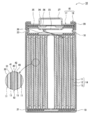
- FIG. 1 is a cross-sectional view of a nonaqueous electrolyte secondary battery 10 which is an example of an embodiment.
- the nonaqueous electrolyte secondary battery 10 includes an electrode body 14, a nonaqueous electrolyte (not shown), and a battery case 15 that houses the electrode body 14 and the nonaqueous electrolyte.
- the electrode body 14 includes a positive electrode 11, a negative electrode 12, and a separator 13, and has a winding structure in which the positive electrode 11 and the negative electrode 12 are wound via the separator 13.
- the battery case 15 includes a bottomed cylindrical outer can 16 and a sealing body 17 that closes an opening of the outer can 16.
- the non-aqueous electrolyte includes a non-aqueous solvent and an electrolyte salt dissolved in the non-aqueous solvent.
- the non-aqueous solvent for example, esters, ethers, nitriles, amides, and a mixed solvent of two or more thereof may be used.
- the non-aqueous solvent may contain a halogen-substituted product in which at least a part of hydrogen in these solvents is substituted with a halogen atom such as fluorine.
- the non-aqueous electrolyte is not limited to a liquid electrolyte, and may be a solid electrolyte using a gel polymer or the like.
- the electrolyte salt a lithium salt such as LiPF 6 is used.
- the nonaqueous electrolyte secondary battery 10 includes insulating plates 18 and 19 disposed above and below the electrode body 14, respectively.
- the positive electrode lead 20 attached to the positive electrode 11 extends to the sealing body 17 side through the through hole of the insulating plate 18, and the negative electrode lead 21 attached to the negative electrode 12 passes outside the insulating plate 19. Extending to the bottom side of the outer can 16.
- the positive electrode lead 20 is connected to the lower surface of the filter 23 which is the bottom plate of the sealing body 17 by welding or the like, and the cap 27 which is the top plate of the sealing body 17 electrically connected to the filter 23 serves as a positive electrode terminal.
- the negative electrode lead 21 is connected to the bottom inner surface of the outer can 16 by welding or the like, and the outer can 16 serves as a negative electrode terminal.
- the outer can 16 is, for example, a bottomed cylindrical metal container.
- a gasket 28 is provided between the outer can 16 and the sealing body 17 to ensure the sealing inside the battery.
- a protruding portion 22 that supports the sealing body 17 is formed in which a part of the side surface portion protrudes inward.
- the overhang portion 22 is preferably formed in an annular shape along the circumferential direction of the outer can 16, and supports the sealing body 17 on its upper surface.
- the sealing body 17 has a structure in which a filter 23, a lower valve body 24, an insulating member 25, an upper valve body 26, and a cap 27 are laminated in this order from the electrode body 14 side.
- Each member which comprises the sealing body 17 has disk shape or a ring shape, for example, and each member except the insulating member 25 is electrically connected mutually.
- the lower valve body 24 and the upper valve body 26 are connected to each other at the center, and an insulating member 25 is interposed between the peripheral edges.
- the positive electrode 11 includes a positive electrode current collector 30 and a positive electrode mixture layer 31 provided on the positive electrode current collector 30.
- a metal foil that is stable within the potential range of the positive electrode 11 such as aluminum or an aluminum alloy, a film in which the metal is disposed on the surface layer, or the like can be used.
- the positive electrode mixture layer 31 includes a positive electrode active material, a conductive material such as acetylene black, and a binder such as polyvinylidene fluoride (PVdF), and is preferably provided on both surfaces of the positive electrode current collector 30.
- PVdF polyvinylidene fluoride
- the positive electrode 11 is formed by applying a positive electrode mixture slurry containing a positive electrode active material, a conductive material, a binder, and the like on the positive electrode current collector 30, drying the coating film, and compressing the positive electrode mixture layer 31. It can be produced by forming on both surfaces of the positive electrode current collector 30.
- a lithium metal composite oxide is used as the positive electrode active material.
- metal elements contained in the lithium metal composite oxide include Ni, Co, Mn, Al, B, Mg, Ti, V, Cr, Fe, Cu, Zn, Ga, Sr, Zr, Nb, In, Sn, Ta, W, etc. are mentioned.
- An example of a suitable lithium metal composite oxide is a lithium metal composite oxide containing at least one of Ni, Co, and Mn. Specific examples include lithium metal composite oxides containing Ni, Co, and Mn, and lithium metal composite oxides containing Ni, Co, and Al. Note that inorganic particles such as tungsten oxide, aluminum oxide, and a lanthanoid-containing compound may be fixed to the surface of the lithium metal composite oxide particles.
- the negative electrode 12 includes a negative electrode current collector 40 and a negative electrode mixture layer 41 provided on the negative electrode current collector 40.
- a metal foil that is stable in the potential range of the negative electrode 12, such as copper, a film in which the metal is disposed on the surface layer, or the like can be used.
- the negative electrode mixture layer 41 includes a negative electrode active material and a binder, and is preferably provided on both surfaces of the negative electrode current collector 40.
- the negative electrode 12 is formed by applying a negative electrode mixture slurry containing a negative electrode active material and a binder on the negative electrode current collector 40, drying the coating film, and then compressing the negative electrode mixture layer 41 to form the negative electrode collector layer 41. It can be produced by forming on both surfaces of the electric body 40.
- the negative electrode mixture layer 41 has a first layer 42 and a second layer 43 formed in this order from the negative electrode current collector 40 side.
- the first layer 42 includes a first carbon-based active material (hereinafter referred to as carbon-based active material A) having a 10% proof stress of 3 MPa or less and a silicon-based active material containing Si.
- the second layer 43 includes a second carbon-based active material (hereinafter referred to as a carbon-based active material B) having a 10% proof stress of 5 MPa or more, and the content (mass ratio) of the silicon-based active material as compared with the first layer 42. ) Is low.
- the carbon-based active materials A and B are negative electrode active materials made of a carbon material, and preferably include graphite as a main component. Examples of graphite include natural graphite such as flake graphite, massive graphite, and earthy graphite, artificial graphite such as massive artificial graphite, and graphitized mesophase carbon microbeads.
- the negative electrode mixture layer 41 may have a third layer, but preferably has a two-layer structure including a first layer 42 and a second layer 43.
- the two-layer structure is preferably formed on both sides of the negative electrode current collector 40.
- the negative electrode mixture layer 41 may contain a negative electrode active material other than the carbon-based active materials A and B and the silicon-based active material as long as the object of the present disclosure is not impaired.
- Carbon-based active materials A and B having different hardnesses are added to the first layer 42 and the second layer 43, respectively.
- the carbon-based active material A of the first layer 42 is softer than the carbon-based active material B of the second layer 43.
- the content of the silicon-based active material is preferably the first layer 42> the second layer 43, and the second layer 43 preferably does not substantially contain the silicon-based active material.
- the content rate of the silicon-based active material in each layer is the ratio of the mass of the silicon-based active material contained in each layer to the total mass of each layer.
- the thickness of the negative electrode mixture layer 41 is, for example, 20 ⁇ m to 120 ⁇ m on one side of the negative electrode current collector 40.
- the thickness of the first layer 42 is preferably 30 to 80%, more preferably 50 to 70% of the thickness of the negative electrode mixture layer 41.
- the thickness of the second layer 43 is preferably 20 to 70%, more preferably 30 to 50% of the thickness of the negative electrode mixture layer 41. In this case, it is easy to achieve both high energy density and good output characteristics.
- the thickness of the second layer 43 may be thinner than the thickness of the first layer 42, for example, or may be substantially the same.
- the silicon-based active material is preferably included only in the first layer 42.
- the silicon-based active material is Si or a compound containing Si, and is preferably a silicon oxide represented by SiO x (0.5 ⁇ x ⁇ 1.6).
- the silicon oxide represented by SiO x has a structure in which Si fine particles are dispersed in an amorphous SiO 2 matrix.
- the silicon-based active material may be a compound represented by Li 2y SiO (2 + y) (0 ⁇ y ⁇ 2) in which Si fine particles are dispersed in a lithium silicate phase.
- a conductive coating composed of a material having higher conductivity than Si or a compound containing Si is formed on the particle surface of the silicon-based active material.
- the constituent material of the conductive film include at least one selected from a carbon material, a metal, and a metal compound.
- a carbon material such as amorphous carbon is preferable.
- the carbon coating can be formed by, for example, a CVD method using acetylene, methane, or the like, a method in which coal pitch, petroleum pitch, phenol resin, or the like is mixed with a silicon-based active material and heat treatment is performed.
- the conductive coating may be formed by fixing a conductive filler such as carbon black to the particle surface of the silicon-based active material using a binder.
- the content of the silicon-based active material in the first layer 42 is, for example, 4 to 20% by mass, preferably 6 to 12% by mass with respect to the total mass of the first layer 42.
- the mixing ratio of the carbon-based active material A and the silicon-based active material is, for example, 1:99 to 20:80 by mass ratio, and preferably 5:95 to 15:85. If the addition amount of the silicon-based active material is within this range, high energy density, good output characteristics, and good cycle characteristics can be easily arranged.
- the volume-based median diameter of the silicon-based active material such as silicon acid represented by SiO x (hereinafter referred to as D50) is preferably 0.5 times or less of D50 of the carbon-based active material A.
- the carbon-based active material A can easily reduce the volume change of the silicon-based active material.
- D50 of the silicon-based active material is, for example, 0.5 to 20 ⁇ m.
- the D50 of the carbon-based active materials A and B is, for example, 5 to 30 ⁇ m.
- the D50 of the silicon-based active material and the carbon-based active materials A and B is measured by, for example, a laser diffraction / scattering particle size distribution measuring apparatus (trade name “LA-920” manufactured by HORIBA).
- the carbon-based active material A is a soft particle having a 10% proof stress of 3 MPa or less.
- the carbon-based active material B is a hard particle having a 10% proof stress of 5 MPa or more.
- the carbon-based active material A relaxes the volume change of the silicon-based active material, and the carbon-based active material B improves output characteristics.
- the carbon-based active material B may be mixed in the first layer 42 and the carbon-based active material A may be mixed in the second layer 43 as long as the object of the present disclosure is not impaired.
- 10% proof stress means the pressure when the particles of the carbon-based active materials A and B are compressed by 10% in volume ratio.
- the 10% proof stress can be measured for each particle of the carbon-based active materials A and B using a micro compression tester (manufactured by Shimadzu Corporation, MCT-211). For the measurement, particles having the same particle diameter as each D50 of the carbon-based active materials A and B are used.
- the carbon-based active material A may not have voids in the particles, but the carbon-based active material B preferably has voids in the particles. Specifically, the carbon-based active material B preferably has a porosity of 1 to 5%. In this case, it becomes easy to enhance output characteristics while ensuring a hardness with a 10% yield strength of 5 MPa or more.
- the porosity of the carbon-based active material A is 2 to 10, for example.
- the porosity of the carbon-based active materials A and B can be measured by creating a cross section of the active material using an ion milling apparatus and observing with a scanning electron microscope (SEM).
- the carbon-based active material A may not substantially contain an amorphous component (amorphous carbon), but the carbon-based active material B preferably contains an amorphous component. Specifically, the carbon-based active material B preferably contains 1 to 5% by mass of an amorphous component. In this case, it becomes easy to ensure 10% yield strength of 5 MPa or more.
- the amount of the amorphous component of the carbon-based active material A is, for example, 0.1 to 2% by mass, which is smaller than the amount of the amorphous component of the carbon-based active material B.
- the amorphous component amount (amorphous carbon amount) of the carbon-based active materials A and B can be quantified by Raman spectroscopic measurement.
- the G band (G-band) peak derived from the graphite structure appears in the vicinity of 1590 cm ⁇ 1
- the D band (D-band) derived from defects in the vicinity of 1350 cm ⁇ 1.
- the peak intensity ratio of D-band / G-band can be used as an index of the amount of amorphous carbon, and the higher the ratio, the larger the amount of amorphous carbon.
- the D-band / G-band ratio can be obtained, for example, by measuring each cross section of the first layer 42 and the second layer 43 by Raman spectroscopy.
- the D-band / G-band ratio (R value) of the first layer 42 is the ratio of the carbon-based active material A ( The same applies to the carbon-based active material B of the second layer 43).
- the D-band / G-band ratio of the carbon-based active material A is preferably 0.05 to 0.2.
- the D-band / G-band ratio of the carbon-based active material B is preferably 0.1 to 2.0.
- the ratio of the D-band / G-band ratio of the Raman spectrum of the second layer 43 to the D-band / G-band ratio of the Raman spectrum of the first layer 42 is preferably 2 to 10, and preferably 4 to 6. More preferred.
- Amorphous carbon is carbon that has not developed a graphite crystal structure, and is amorphous or microcrystalline and in a turbulent structure. More specifically, it means a component having a d (002) plane spacing of 0.342 nm or more by X-ray diffraction.
- Specific examples of the amorphous carbon include hard carbon (non-graphitizable carbon), soft carbon (graphitizable carbon), carbon black, carbon fiber, activated carbon, and the like.
- Amorphous carbon is obtained, for example, by carbonizing a resin or a resin composition.
- phenol-based thermosetting resins, thermoplastic resins such as polyacrylonitrile, petroleum-based or coal-based tar, pitch, and the like can be used.
- Carbon black can be obtained, for example, by pyrolyzing a hydrocarbon as a raw material (pyrolysis method, incomplete combustion method).
- thermal decomposition method include a thermal method and an acetylene decomposition method.
- acetylene decomposition method examples include a contact method, a lamp / pine smoke method, a gas furnace method, and an oil furnace method.
- Specific examples of carbon black obtained by these production methods include acetylene black, ketjen black, thermal black, and furnace black.
- the amorphous carbon is preferably present in a state of being fixed to the surface of the graphite-based carbon.
- adherered means a state in which the material is chemically and / or physically bonded, and even if the negative electrode active material is stirred in water or an organic solvent, it is amorphous from the surface of the graphite-based carbon. It means that carbon is not liberated.
- the physical property and the fixed amount of amorphous carbon of the carbon-based active material can be adjusted by, for example, the type and amount of raw materials (petroleum or coal-based tar, pitch, etc.), the temperature of carbonization, time, and the like.
- the carbon-based active material B contained in the second layer 43 preferably has a 10% yield strength of 5 MPa or more and a porosity of 1 to 5%.
- a carbon-based active material B includes, for example, a core part having a void and a shell part arranged so as to cover the core part.
- the core part is preferably composed of graphite and amorphous carbon and has a void inside.
- the shell portion is made of amorphous carbon, and the thickness is preferably 50 nm or more.
- the weight ratio of the core part to the shell part is desirably 99: 1 to 95: 5.
- the porosity of the shell part is preferably lower than the porosity of the core part.
- the core portion has a porosity of 1 to 5% and the shell portion has a porosity of 0.01 to 1%.
- the carbon-based active material B having a shell portion with a certain thickness or more and a low porosity is improved in 10% proof stress.
- the core part is a mixture of graphite and a graphitizable binder and heated to 500 to 3000 ° C. in an inert gas atmosphere or a non-oxidizing atmosphere to pulverize, crush and classify the carbonized material.
- graphite include natural graphite and artificial graphite.
- Artificial graphite includes powders fired from coke such as needle coke and mosaic coke.
- the average particle diameter of graphite is 10 ⁇ m or less, more desirably 5 ⁇ m or less. This is because the use of graphite having a small particle diameter facilitates the generation of voids inside the particles and improves the output characteristics.
- Examples of the graphitizable binder include coal-based, petroleum-based, artificial-based pitches and tars, thermoplastic resins, thermosetting resins, and the like. Moreover, in order to form a space
- the method of mixing the graphite and the binder is not particularly limited, but mixing with an apparatus capable of applying compressive shear is preferable because the binder is more uniformly disposed and a harder powder can be formed.
- the mixing ratio is not limited, but the ratio of the residual carbon content of the binder component to graphite is preferably 1:99 to 30:70.
- the temperature at which the heat treatment is performed is not particularly limited, but is preferably 1500 ° C. or higher, and may be performed at 2500 ° C. or higher.
- the shell portion can be formed by a CVD method using acetylene, methane, or the like, a method in which coal pitch, petroleum pitch, phenol resin, or the like is mixed with the carbon material of the core portion and subjected to heat treatment.
- the carbon-based active material B can be obtained.
- a fluorine resin, a PAN, a polyimide resin, an acrylic resin, a polyolefin resin, or the like can be used for the binder contained in the negative electrode mixture layer 41, but preferably a styrene butadiene rubber. (SBR) is used.
- the negative electrode mixture layer 41 preferably further contains CMC or a salt thereof, polyacrylic acid (PAA) or a salt thereof, polyvinyl alcohol, or the like.
- the type and amount of the binder used may be changed between the first layer 42 and the second layer 43.
- the first layer 42 preferably contains PAA or a salt thereof together with SBR and CMC or a salt thereof.
- PAA or a salt thereof has strong adhesion to the silicon-based active material, and the strength of the first layer 42 can be increased by using this.
- the content of PAA or a salt thereof is preferably 0.1 to 3% by mass and more preferably 0.5 to 2% by mass with respect to the total mass of the first layer 42.
- the content of PAA or a salt thereof can be measured by microscopic Raman spectroscopy, SEM-EDX or the like.
- the separator 13 a porous sheet having ion permeability and insulating properties is used. Specific examples of the porous sheet include a microporous thin film, a woven fabric, and a nonwoven fabric.
- an olefin resin such as polyethylene or polypropylene, cellulose, or the like is preferable.
- the separator 13 may have either a single layer structure or a laminated structure. A heat resistant layer or the like may be formed on the surface of the separator 13.
- Example 1 [Production of positive electrode]
- a lithium-containing transition metal oxide represented by Li 1.0 Ni 0.5 Co 0.2 Mn 0.3 O 2 was used as the positive electrode active material.
- the positive electrode active material, acetylene black, and PVdF were mixed at a mass ratio of 94.8: 4: 1.2, and an appropriate amount of N-methyl-2-pyrrolidone was added to prepare a positive electrode mixture slurry.
- the positive electrode mixture slurry is applied to both surfaces of a positive electrode current collector made of an aluminum foil, leaving portions where leads are connected, and after drying the coating film, the coating film is rolled using a roller. It cut
- the first negative electrode mixture slurry for the first layer was prepared by mixing at a mass ratio of 1 and adding an appropriate amount of water.
- the first negative electrode mixture slurry was applied to both surfaces of a negative electrode current collector made of copper foil, leaving portions where leads were connected, and the coating film was dried to form a first layer.
- the second negative electrode mixture slurry was applied on the first layer, and the coating film was dried to form a second layer.
- the negative electrode compound material layer which rolls a coating film (1st layer and 2nd layer) using a roller, cut
- a negative electrode formed with was prepared.
- the thickness ratio of the second layer / first layer was 2.0.
- LiPF 6 was dissolved in a mixed solvent in which ethylene carbonate (EC) and ethyl methyl carbonate (EMC) were mixed at a volume ratio of 3: 7 to a concentration of 1.0 mol / liter. Furthermore, vinylene carbonate (VC) was dissolved in the above mixed solvent at a concentration of 2% by volume to prepare a nonaqueous electrolyte.
- EC ethylene carbonate
- EMC ethyl methyl carbonate
- VC vinylene carbonate
- Electrode body was accommodated in a battery exterior body composed of an aluminum laminate sheet, and after the nonaqueous electrolyte was injected, the exterior body was sealed to produce a test cell (laminate cell) having a design capacity of 640 mAh.
- the amount of the amorphous component of the carbon-based active material contained in the negative electrode mixture layer (first layer and second layer) was evaluated by Raman spectroscopic measurement.
- the peak intensity ratio (R value) of D-band / G-band in the Raman spectrum of the carbon-based active material can be used as an index of the amount of amorphous carbon as described above, and the higher the ratio, the more amorphous carbon Means a lot.
- the first layer and the second layer were subjected to Raman spectroscopic measurement to determine the D-band / G-band ratio of each layer, and the amorphous component amount was calculated from the ratio.
- the BET specific surface area of the carbon-based active material was measured using TriStar manufactured by micromeritics.
- the cycle test was performed under the following conditions, the resistance value after 200 cycles was obtained by the above method, and the increase rate of the resistance value after 200 cycles with respect to the resistance value before the cycle test was calculated.
- Example 2 Other than using carbon-based active material B, graphite having a 10% proof stress of 6.6 MPa, a porosity of 2%, an amorphous component amount of 1.5% by mass, and a BET specific surface area of 4.4 m 2 / g. Produced a negative electrode and a test cell in the same manner as in Example 1.
- Example 3 Other than using carbon-based active material B, graphite having a 10% proof stress of 27 MPa, a porosity of 3.1%, an amorphous component amount of 4.0% by mass, and a BET specific surface area of 3.0 m 2 / g. Produced a negative electrode and a test cell in the same manner as in Example 1.
- Carbon-based active material B graphite having a 10% proof stress of 2.1 MPa, a porosity of 4.2%, an amorphous component amount of 0.6% by mass, and a BET specific surface area of 4.0 m 2 / g is used.
Landscapes
- Chemical & Material Sciences (AREA)
- Chemical Kinetics & Catalysis (AREA)
- Electrochemistry (AREA)
- General Chemical & Material Sciences (AREA)
- Engineering & Computer Science (AREA)
- Composite Materials (AREA)
- Materials Engineering (AREA)
- Manufacturing & Machinery (AREA)
- Inorganic Chemistry (AREA)
- Battery Electrode And Active Subsutance (AREA)
Abstract
非水電解質二次電池において、負極合材層は、負極集電体側から順に形成された第1層及び第2層を有する。第1層は、10%耐力が3MPa以下の第1の炭素系活物質と、Siを含有するシリコン系活物質とを含む。第2層は、10%耐力が5MPa以上の第2の炭素系活物質を含み、第1層よりもシリコン系活物質の含有率(質量比)が低い。
Description
本開示は、非水電解質二次電池用負極及び非水電解質二次電池に関する。
従来、SiOxで表されるシリコン酸化物などのSiを含有する化合物は、黒鉛などの炭素系活物質と比べて単位体積当りに多くのリチウムイオンを吸蔵できることが知られている。負極活物質として、Siを含有するシリコン系活物質を用いることにより、電池の高エネルギー密度化を図ることができる。また、非晶質成分を多く含む硬い黒鉛粒子を用いることで、電池の出力特性が向上することが知られている。特許文献1には、出力特性等の電池性能を改善すべく、負極合材層の集電体側領域と表面側領域とで粒子形状の異なる炭素系活物質を用いた非水電解質二次電池が提案されている。
近年、高エネルギー密度で、かつ出力特性に優れた非水電解質二次電池が求められているが、特許文献1の技術を含む従来の技術は未だ改良の余地が大きい。例えば、エネルギー密度及び出力特性を改善すべく、単純にシリコン系活物質と非晶質成分を多く含む硬い黒鉛粒子とを併用した場合、当該黒鉛粒子がシリコン系活物質の体積変化に追従できず、負極合材層内の導電パスが切断され、抵抗値が大幅に増加するという問題がある。
本開示の一態様である非水電解質二次電池用負極は、負極集電体と、前記負極集電体上に設けられた負極合材層とを備える非水電解質二次電池用負極であって、前記負極合材層は、前記負極集電体側から順に形成された第1層及び第2層を有し、前記第1層は、10%耐力が3MPa以下の第1の炭素系活物質と、Siを含有するシリコン系活物質とを含み、前記第2層は、10%耐力が5MPa以上の第2の炭素系活物質を含み、前記第1層よりも前記シリコン系活物質の含有率(質量比)が低いことを特徴とする。
本開示の一態様である非水電解質二次電池は、上記負極と、正極と、セパレータと、非水電解質とを備える。
本開示の一態様によれば、高エネルギー密度で、かつ出力特性に優れた非水電解質二次電池を提供できる。
上述のように、非水電解質二次電池において、高いエネルギー密度と優れた出力特性を両立することは重要な課題である。本発明者らは、かかる課題を解決すべく鋭意検討した結果、上述の第1層及び第2層を含む負極合材層を用いることにより、高エネルギー密度で、かつ出力特性に優れた非水電解質二次電池を実現することに成功した。シリコン系活物質と10%耐力が小さな柔らかい炭素系活物質とを含む第1層、及び10%耐力が大きな硬い炭素系活物質を含む第2層を設けることで、充放電に伴うシリコン系活物質の大きな体積変化に起因して発生し得る導電パスの切断が抑制され、その結果、良好な出力特性が長期にわたって維持されると考えられる。
炭素系活物質の硬さは、黒鉛化度、非晶質成分量、及び粒子内部の空隙量に依存する。一般的に、黒鉛化度が高くなるほど、また非晶質成分の割合が多くなるほど、炭素系活物質は硬くなり10%耐力は大きくなる。空隙量が多くなるほど出力特性には有利であるが、例えば黒鉛化度を上げるために活物質の焼成温度を上げると、空隙は減少する。詳しくは後述するが、本発明者らは、小粒径の核黒鉛を使用して、ピッチ材との混合方法、焼成温度を工夫することにより、硬さと高い空隙率を有する黒鉛を合成することに成功した。第2層には、当該黒鉛を用いることが好適である。以下、図面を参照しながら実施形態の一例について詳細に説明する。
以下では、巻回型の電極体14が円筒形の電池ケースに収容された円筒形電池を例示するが、電極体は、巻回型に限定されず、複数の正極と複数の負極がセパレータを介して交互に積層されてなる積層型であってもよい。また、本開示に係る非水電解質二次電池は、角形の金属製ケースを備える角形電池、コイン形の金属製ケースを備えるコイン形電池等であってもよく、金属層及び樹脂層を含むラミネートシートで構成された外装体を備えるラミネート電池であってもよい。
図1は、実施形態の一例である非水電解質二次電池10の断面図である。図1に例示するように、非水電解質二次電池10は、電極体14と、非水電解質(図示せず)と、電極体14及び非水電解質を収容する電池ケース15とを備える。電極体14は、正極11と、負極12と、セパレータ13とを備え、正極11と負極12がセパレータ13を介して巻回された巻回構造を有する。電池ケース15は、有底円筒形状の外装缶16と、外装缶16の開口部を塞ぐ封口体17とで構成されている。
非水電解質は、非水溶媒と、非水溶媒に溶解した電解質塩とを含む。非水溶媒には、例えばエステル類、エーテル類、ニトリル類、アミド類、およびこれらの2種以上の混合溶媒等を用いてもよい。非水溶媒は、これら溶媒の水素の少なくとも一部をフッ素等のハロゲン原子で置換したハロゲン置換体を含有していてもよい。なお、非水電解質は液体電解質に限定されず、ゲル状ポリマー等を用いた固体電解質であってもよい。電解質塩には、LiPF6等のリチウム塩が使用される。
非水電解質二次電池10は、電極体14の上下にそれぞれ配置された絶縁板18,19を備える。図1に示す例では、正極11に取り付けられた正極リード20が絶縁板18の貫通孔を通って封口体17側に延び、負極12に取り付けられた負極リード21が絶縁板19の外側を通って外装缶16の底部側に延びている。正極リード20は封口体17の底板であるフィルタ23の下面に溶接等で接続され、フィルタ23と電気的に接続された封口体17の天板であるキャップ27が正極端子となる。負極リード21は外装缶16の底部内面に溶接等で接続され、外装缶16が負極端子となる。
外装缶16は、例えば有底円筒形状の金属製容器である。外装缶16と封口体17との間にはガスケット28が設けられ、電池内部の密閉性が確保されている。外装缶16には、例えば側面部の一部が内側に張り出した、封口体17を支持する張出部22が形成されている。張出部22は、外装缶16の周方向に沿って環状に形成されることが好ましく、その上面で封口体17を支持する。
封口体17は、電極体14側から順に、フィルタ23、下弁体24、絶縁部材25、上弁体26、及びキャップ27が積層された構造を有する。封口体17を構成する各部材は、例えば円板形状又はリング形状を有し、絶縁部材25を除く各部材は互いに電気的に接続されている。下弁体24と上弁体26は各々の中央部で互いに接続され、各々の周縁部の間には絶縁部材25が介在している。異常発熱で電池の内圧が上昇すると、下弁体24が上弁体26をキャップ27側に押し上げるように変形して破断し、下弁体24と上弁体26の間の電流経路が遮断される。さらに内圧が上昇すると、上弁体26が破断し、キャップ27の開口部からガスが排出される。
以下、電極体14の各構成要素について、特に負極12について詳説する。
[正極]
正極11は、正極集電体30と、正極集電体30上に設けられた正極合材層31とを有する。正極集電体30には、アルミニウム、アルミニウム合金など正極11の電位範囲で安定な金属の箔、当該金属を表層に配置したフィルム等を用いることができる。正極合材層31は、正極活物質、アセチレンブラック等の導電材、及びポリフッ化ビニリデン(PVdF)等の結着材を含み、正極集電体30の両面に設けられることが好ましい。正極11は、正極集電体30上に正極活物質、導電材、及び結着材等を含む正極合材スラリーを塗布し、塗膜を乾燥させた後、圧縮して正極合材層31を正極集電体30の両面に形成することにより作製できる。
正極11は、正極集電体30と、正極集電体30上に設けられた正極合材層31とを有する。正極集電体30には、アルミニウム、アルミニウム合金など正極11の電位範囲で安定な金属の箔、当該金属を表層に配置したフィルム等を用いることができる。正極合材層31は、正極活物質、アセチレンブラック等の導電材、及びポリフッ化ビニリデン(PVdF)等の結着材を含み、正極集電体30の両面に設けられることが好ましい。正極11は、正極集電体30上に正極活物質、導電材、及び結着材等を含む正極合材スラリーを塗布し、塗膜を乾燥させた後、圧縮して正極合材層31を正極集電体30の両面に形成することにより作製できる。
正極活物質には、例えばリチウム金属複合酸化物が用いられる。リチウム金属複合酸化物に含有される金属元素としては、Ni、Co、Mn、Al、B、Mg、Ti、V、Cr、Fe、Cu、Zn、Ga、Sr、Zr、Nb、In、Sn、Ta、W等が挙げられる。好適なリチウム金属複合酸化物の一例は、Ni、Co、Mnの少なくとも1種を含有するリチウム金属複合酸化物である。具体例としては、Ni、Co、Mnを含有するリチウム金属複合酸化物、Ni、Co、Alを含有するリチウム金属複合酸化物が挙げられる。なお、リチウム金属複合酸化物の粒子表面には、酸化タングステン、酸化アルミニウム、ランタノイド含有化合物等の無機物粒子などが固着していてもよい。
[負極]
負極12は、負極集電体40と、負極集電体40上に設けられた負極合材層41とを有する。負極集電体40には、銅など負極12の電位範囲で安定な金属の箔、当該金属を表層に配置したフィルム等を用いることができる。負極合材層41は、負極活物質、及び結着材を含み、負極集電体40の両面に設けられることが好ましい。負極12は、例えば負極集電体40上に負極活物質、及び結着材等を含む負極合材スラリーを塗布し、塗膜を乾燥させた後、圧縮して負極合材層41を負極集電体40の両面に形成することにより作製できる。
負極12は、負極集電体40と、負極集電体40上に設けられた負極合材層41とを有する。負極集電体40には、銅など負極12の電位範囲で安定な金属の箔、当該金属を表層に配置したフィルム等を用いることができる。負極合材層41は、負極活物質、及び結着材を含み、負極集電体40の両面に設けられることが好ましい。負極12は、例えば負極集電体40上に負極活物質、及び結着材等を含む負極合材スラリーを塗布し、塗膜を乾燥させた後、圧縮して負極合材層41を負極集電体40の両面に形成することにより作製できる。
負極合材層41は、負極集電体40側から順に形成された第1層42及び第2層43を有する。第1層42は、10%耐力が3MPa以下の第1の炭素系活物質(以下、炭素系活物質Aとする)と、Siを含有するシリコン系活物質とを含む。第2層43は、10%耐力が5MPa以上の第2の炭素系活物質(以下、炭素系活物質Bとする)を含み、第1層42よりもシリコン系活物質の含有率(質量比)が低い。炭素系活物質A,Bは、炭素材料からなる負極活物質であって、黒鉛を主成分とすることが好ましい。黒鉛としては、鱗片状黒鉛、塊状黒鉛、土状黒鉛等の天然黒鉛、塊状人造黒鉛、黒鉛化メソフェーズカーボンマイクロビーズ等の人造黒鉛が例示できる。
負極合材層41は、第3の層を有していてもよいが、好ましくは第1層42及び第2層43からなる2層構造を有する。当該2層構造は、負極集電体40の両側に形成されることが好ましい。なお、負極合材層41には、本開示の目的を損なわない範囲で、炭素系活物質A,B及びシリコン系活物質以外の負極活物質が含まれていてもよい。
第1層42及び第2層43には、硬さの異なる炭素系活物質A,Bがそれぞれ添加される。第1層42の炭素系活物質Aは、第2層43の炭素系活物質Bよりも柔らかい。また、シリコン系活物質の含有率は第1層42>第2層43であり、第2層43は実質的にシリコン系活物質を含まないことが好ましい。各層のシリコン系活物質の含有率は、各層の総質量に対する、各層に含まれるシリコン系活物質の質量の比率である。負極合材層41を当該2層構造とすることで、高エネルギー密度で、かつ優れた出力特性が得られる。充放電に伴うシリコン系活物質の大きな体積変化を柔らかい炭素系活物質Aが緩和して導電パスの切断を抑制しつつ、硬い炭素系活物質Bにより良好な出力特性が確保されると考えられる。
負極合材層41の厚みは、例えば負極集電体40の片側で20μm~120μmである。第1層42の厚みは、負極合材層41の厚みの30~80%が好ましく、50~70%がより好ましい。第2層43の厚みは、負極合材層41の厚みの20~70%が好ましく、30~50%がより好ましい。この場合、高いエネルギー密度と良好な出力特性を両立し易い。第2層43の厚みは、例えば第1層42の厚みより薄くてもよく、略同じであってもよい。
シリコン系活物質は、上述のように、第1層42のみに含まれることが好ましい。シリコン系活物質は、Si又はSiを含有する化合物であって、好ましくはSiOx(0.5≦x≦1.6)で表されるシリコン酸化物である。SiOxで表されるシリコン酸化物は、非晶質のSiO2マトリックス中にSiの微粒子が分散した構造を有する。また、シリコン系活物質は、リチウムシリケート相中にSiの微粒子が分散した、Li2ySiO(2+y)(0<y<2)で表される化合物であってもよい。
シリコン系活物質の粒子表面には、Si又はSiを含有する化合物よりも導電性の高い材料で構成される導電被膜が形成されていることが好ましい。導電被膜の構成材料としては、炭素材料、金属、及び金属化合物から選択される少なくとも1種が例示できる。中でも、非晶質炭素等の炭素材料が好ましい。炭素被膜は、例えばアセチレン、メタン等を用いたCVD法、石炭ピッチ、石油ピッチ、フェノール樹脂等をシリコン系活物質と混合し、熱処理を行う方法などで形成できる。また、カーボンブラック等の導電フィラーを結着材を用いてシリコン系活物質の粒子表面に固着させることで導電被膜を形成してもよい。
第1層42におけるシリコン系活物質の含有量は、第1層42の総質量に対して、例えば4~20質量%であり、好ましくは6~12質量%である。炭素系活物質Aとシリコン系活物質との混合比率は、例えば質量比で1:99~20:80であり、好ましくは5:95~15:85である。シリコン系活物質の添加量が当該範囲内であれば、高いエネルギー密度と良好な出力特性、また良好なサイクル特性を並立し易い。
SiOxで表されるシリコン酸等のシリコン系活物質の体積基準のメジアン径(以下、D50とする)は、炭素系活物質AのD50の0.5倍以下であることが好ましい。この場合、炭素系活物質Aによってシリコン系活物質の体積変化を緩和することが容易になる。シリコン系活物質のD50は、例えば0.5~20μmである。シリコン系活物質の粒径が小さい方が充放電に伴う体積変化が小さくなる傾向にある。炭素系活物質A,BのD50は、例えば5~30μmである。シリコン系活物質及び炭素系活物質A,BのD50は、例えばレーザー回折散乱式粒子径分布測定装置(HORIBA製、商品名「LA-920」)により測定される。
上述のように、炭素系活物質Aは10%耐力が3MPa以下の柔らかい粒子である。他方、炭素系活物質Bは10%耐力が5MPa以上の硬い粒子である。炭素系活物質Aはシリコン系活物質の体積変化を緩和し、炭素系活物質Bは出力特性を向上させる。負極12の表面側に炭素系活物質Bを含む第2層43を、負極集電体40側にシリコン系活物質及び炭素系活物質Aを含む第1層42をそれぞれ設けることで、高出力と高エネルギー密度を効率良く実現でき、またサイクル特性も向上する。なお、本開示の目的を損なわない範囲で、第1層42に炭素系活物質Bが、第2層43に炭素系活物質Aが混在していてもよい。
本明細書において、10%耐力とは、炭素系活物質A,Bの粒子が体積比率で10%圧縮された際の圧力を意味する。10%耐力は、炭素系活物質A,Bの粒子1個について、微小圧縮試験機(株式会社島津製作所製、MCT-211)等を用いて測定できる。当該測定には、炭素系活物質A,Bの各D50と同等の粒子径の粒子を用いる。
炭素系活物質Aは粒子内に空隙を有していなくてもよいが、炭素系活物質Bは粒子内に空隙を有することが好ましい。具体的に、炭素系活物質Bは、1~5%の空隙率を有することが好適である。この場合、10%耐力が5MPa以上の硬さを確保しながら、出力特性を高めることが容易になる。炭素系活物質Aの空隙率は、例えば2~10である。炭素系活物質A,Bの空隙率は、イオンミリング装置を使用して活物質の断面を作成し、走査型電子顕微鏡(SEM)よって観察することで測定できる。
炭素系活物質Aは非晶質成分(非晶質炭素)を実質的に含有していなくてもよいが、炭素系活物質Bは非晶質成分を含有することが好ましい。具体的に、炭素系活物質Bは、1~5質量%の非晶質成分を含有することが好適である。この場合、5MPa以上の10%耐力を確保することが容易になる。炭素系活物質Aの非晶質成分量は、例えば0.1~2質量%であり、炭素系活物質Bの非晶質成分量よりも少ない。
炭素系活物質A,Bの非晶質成分量(非晶質炭素量)は、ラマン分光測定により定量できる。炭素系活物質A,Bのラマンスペクトルには、1590cm-1付近にグラファイト構造に由来するGバンド(G-band)のピークが、1350cm-1付近に欠陥に由来するDバンド(D-band)のピークがそれぞれ現れる。D-band/G-bandのピーク強度比は、非晶質炭素量の指標として使用でき、当該比率が高いほど非晶質炭素量が多いことを意味する。
D-band/G-band比は、例えば第1層42及び第2層43の各断面をラマン分光測定することで求められる。第1層42に炭素系活物質として炭素系活物質Aのみが含まれる場合、第1層42のD-band/G-band比(R値)は炭素系活物質Aの当該比率となる(第2層43の炭素系活物質Bについても同様)。炭素系活物質AのD-band/G-band比は、0.05~0.2が好ましい。炭素系活物質BのD-band/G-band比は、0.1~2.0が好ましい。第1層42のラマン分光スペクトルのD-band/G-band比に対する、第2層43のラマン分光スペクトルのD-band/G-band比の比率は、2~10が好ましく、4~6がより好ましい。
非晶質炭素は、グラファイト結晶構造が発達していない炭素であって、アモルファス又は微結晶で乱層構造な状態の炭素である。より具体的には、X線回折によるd(002)面間隔が0.342nm以上である成分を意味する。非晶質炭素の具体例としては、ハードカーボン(難黒鉛化炭素)、ソフトカーボン(易黒鉛化炭素)、カーボンブラック、カーボンファイバー、活性炭などが挙げられる。非晶質炭素は、例えば樹脂又は樹脂組成物を炭化処理することで得られる。非晶質炭素の原料には、フェノール系の熱硬化性樹脂、ポリアクリロニトリル等の熱可塑性樹脂、石油系又は石炭系のタール、ピッチなどを用いることができる。
カーボンブラックは、例えば原料となる炭化水素を熱分解(熱分解法、不完全燃焼法)することにより得られる。熱分解法としては、サーマル法、アセチレン分解法等が挙げられる。不完全燃焼法としては、コンタクト法、ランプ・松煙法、ガスファーネス法、オイルファーネス法等が挙げられる。これらの製造方法により得られるカーボンブラックの具体例としては、アセチレンブラック、ケッチェンブラック、サーマルブラック、ファーネスブラック等が挙げられる。
非晶質炭素は、黒鉛系炭素の表面に固着した状態で存在することが好ましい。ここで、固着しているとは、化学的及び/又は物理的に結合している状態であって、負極活物質を水や有機溶剤中で攪拌しても黒鉛系炭素の表面から非晶質炭素が遊離しないことを意味する。炭素系活物質の非晶質炭素の物性及び固着量は、例えば原料(石油系又は石炭系のタール、ピッチ等)の種類、量、炭化処理の温度、時間等により調整できる。
第2層43に含まれる炭素系活物質Bは、上述のように、10%耐力が5MPa以上の硬さと、1~5%の空隙率を有することが好ましい。このような炭素系活物質Bは、例えば、空隙を有するコア部とコア部を覆うように配置されるシェル部からなる。コア部は、黒鉛及び非晶質炭素から構成され、内部に空隙を有する構造であることが望ましい。シェル部は、非晶質炭素から構成され、厚みは50nm以上が好ましい。コア部とシェル部の重量比率は99:1~95:5が望ましい。シェル部の空隙率は、コア部の空隙率より低いことが好ましい。コア部の空隙率は1~5%、シェル部分の空隙率は0.01~1%であることが望ましい。シェル部が一定以上の厚みを持ち、空隙率が少ない炭素系活物質Bは、10%耐力が向上する。炭素活物質Bを用いることで、負極12を圧縮する際に粒子が崩壊して、内部のコア部の空隙を維持することができなくなり、出力が低下することを抑制することができる。
例えば、コア部は、黒鉛と、黒鉛化可能なバインダーを混合物し、不活性ガス雰囲気下、あるいは非酸化性雰囲気下で500~3000℃に加熱し、炭素化物質を粉砕、解砕、分級処理・球形化処理などの粉体加工により作成される。黒鉛は、天然黒鉛や人造黒鉛が例示される。人造黒鉛はニードルコークス、モザイクコークスなどのコークスから焼成される粉末を挙げることができる。黒鉛の平均粒子径は、10μm以下、より望ましくは5μm以下である。小さい粒子径の黒鉛を使用することで、粒子内部の空隙が発生しやすくなり、出力特性が向上するためである。
上記黒鉛化可能なバインダーとしては、石炭系、石油系、人造系等のピッチ及びタール、熱可塑性樹脂、熱硬化性樹脂などが挙げられる。また、空隙を形成するため、残炭率の小さな添加物を混合するとより好ましい。黒鉛とバインダーの混合の方法は特に限定されないが、圧縮せん断を印加できる機器で混合すると、より均一にバインダーが配置されることとなり、より固い粉末を形成することができるため、好ましい。これらの混合比率は限定されないが、バインダー成分の残留炭素分と黒鉛との比率は1:99~30:70とすることが好ましい。熱処理をする際の温度は特に限定されないが、1500℃以上であることが望ましく、2500℃以上で行ってもよい。
例えば、シェル部は、アセチレン、メタン等を用いたCVD法、石炭ピッチ、石油ピッチ、フェノール樹脂等をコア部の炭素材料と混合し、熱処理を行う方法などで形成できる。上記のような作製方法を用いることで、炭素系活物質Bを得ることができる。
負極合材層41に含まれる結着材には、正極11の場合と同様に、フッ素樹脂、PAN、ポリイミド樹脂、アクリル樹脂、ポリオレフィン樹脂等を用いることも可能であるが、好ましくはスチレンブタジエンゴム(SBR)が用いられる。負極合材層41は、さらに、CMC又はその塩、ポリアクリル酸(PAA)又はその塩、ポリビニルアルコールなどを含むことが好ましい。第1層42と第2層43とで、使用する結着材の種類及び量を変更してもよい。
第1層42は、SBRとCMC又はその塩と共に、PAA又はその塩を含むことが好ましい。PAA又はその塩はシリコン系活物質に対する密着力が強く、これを用いることで、第1層42の強度を高めることができる。PAA又はその塩の含有量は、第1層42の総質量に対して、0.1~3質量%が好ましく、0.5~2質量%がより好ましい。PAA又はその塩の含有量は顕微ラマン分光法、SEM-EDX等により測定できる。
[セパレータ]
セパレータ13には、イオン透過性及び絶縁性を有する多孔性シートが用いられる。多孔性シートの具体例としては、微多孔薄膜、織布、不織布等が挙げられる。セパレータ13の材質としては、ポリエチレン、ポリプロピレン等のオレフィン樹脂、セルロースなどが好適である。セパレータ13は、単層構造、積層構造のいずれであってもよい。セパレータ13の表面には、耐熱層などが形成されていてもよい。
セパレータ13には、イオン透過性及び絶縁性を有する多孔性シートが用いられる。多孔性シートの具体例としては、微多孔薄膜、織布、不織布等が挙げられる。セパレータ13の材質としては、ポリエチレン、ポリプロピレン等のオレフィン樹脂、セルロースなどが好適である。セパレータ13は、単層構造、積層構造のいずれであってもよい。セパレータ13の表面には、耐熱層などが形成されていてもよい。
以下、実施例により本開示をさらに説明するが、本開示はこれらの実施例に限定されるものではない。
<実施例1>
[正極の作製]
正極活物質として、Li1.0Ni0.5Co0.2Mn0.3O2で表されるリチウム含有遷移金属酸化物を用いた。当該正極活物質と、アセチレンブラックと、PVdFとを、94.8:4:1.2の質量比で混合し、N-メチル-2-ピロリドンを適量加えて、正極合材スラリーを調製した。当該正極合材スラリーをアルミニウム箔からなる正極集電体の両面に、リードが接続される部分を残して塗布し、塗膜を乾燥させた後、ローラーを用いて塗膜を圧延し、所定の電極サイズに切断して、正極集電体の両面に正極合材層が形成された正極を作製した。
[正極の作製]
正極活物質として、Li1.0Ni0.5Co0.2Mn0.3O2で表されるリチウム含有遷移金属酸化物を用いた。当該正極活物質と、アセチレンブラックと、PVdFとを、94.8:4:1.2の質量比で混合し、N-メチル-2-ピロリドンを適量加えて、正極合材スラリーを調製した。当該正極合材スラリーをアルミニウム箔からなる正極集電体の両面に、リードが接続される部分を残して塗布し、塗膜を乾燥させた後、ローラーを用いて塗膜を圧延し、所定の電極サイズに切断して、正極集電体の両面に正極合材層が形成された正極を作製した。
[第1負極合材スラリーの調製]
10%耐力が2.1MPaである黒鉛(炭素系活物質A)と、炭素被膜を有するSiOx(x=0.94)と、CMCのナトリウム塩と、SBRとを、88:9:1:1の質量比で混合し、水を適量加えて、第1層用の第1負極合材スラリーを調製した。
10%耐力が2.1MPaである黒鉛(炭素系活物質A)と、炭素被膜を有するSiOx(x=0.94)と、CMCのナトリウム塩と、SBRとを、88:9:1:1の質量比で混合し、水を適量加えて、第1層用の第1負極合材スラリーを調製した。
[第2負極合材スラリーの調製]
10%耐力が5.7MPaである黒鉛(炭素系活物質B)と、PAAのリチウム塩と、CMCのナトリウム塩と、SBRとを、97:1:1:1の質量比で混合し、水を適量加えて、第2層用の第2負極合材スラリーを調製した。
10%耐力が5.7MPaである黒鉛(炭素系活物質B)と、PAAのリチウム塩と、CMCのナトリウム塩と、SBRとを、97:1:1:1の質量比で混合し、水を適量加えて、第2層用の第2負極合材スラリーを調製した。
[負極の作製]
第1負極合材スラリーを銅箔からなる負極集電体の両面に、リードが接続される部分を残して塗布し、塗膜を乾燥させて第1層を形成した。次に、第2負極合材スラリーを第1層上に塗布し、塗膜を乾燥させて第2層を形成した。そして、ローラーを用いて塗膜(第1層及び第2層)を圧延し、所定の電極サイズに切断して、負極集電体の両面に第1層及び第2層を含む負極合材層が形成された負極を作製した。負極合材層の第1層及び第2層の厚みを測定した結果、第2層/第1層の厚み比は2.0であった。
第1負極合材スラリーを銅箔からなる負極集電体の両面に、リードが接続される部分を残して塗布し、塗膜を乾燥させて第1層を形成した。次に、第2負極合材スラリーを第1層上に塗布し、塗膜を乾燥させて第2層を形成した。そして、ローラーを用いて塗膜(第1層及び第2層)を圧延し、所定の電極サイズに切断して、負極集電体の両面に第1層及び第2層を含む負極合材層が形成された負極を作製した。負極合材層の第1層及び第2層の厚みを測定した結果、第2層/第1層の厚み比は2.0であった。
[非水電解質の調製]
エチレンカーボネート(EC)と、エチルメチルカーボネート(EMC)とを、3:7の体積比で混合した混合溶媒に、LiPF6を1.0モル/リットルの濃度になるように溶解した。さらに、ビニレンカーボネート(VC)を上記混合溶媒に対して2体積%の濃度で溶解させて、非水電解質を調製した。
エチレンカーボネート(EC)と、エチルメチルカーボネート(EMC)とを、3:7の体積比で混合した混合溶媒に、LiPF6を1.0モル/リットルの濃度になるように溶解した。さらに、ビニレンカーボネート(VC)を上記混合溶媒に対して2体積%の濃度で溶解させて、非水電解質を調製した。
[試験セルの作製]
上記正極及び上記負極にリードをそれぞれ取り付け、ポリプロピレン製のセパレータを介して各電極を渦巻き状に巻回して巻回構造の電極体を作製した。当該電極体をアルミラミネートシートで構成される電池外装体内に収容し、上記非水電解質を注入した後、外装体を封止して、設計容量640mAhの試験セル(ラミネートセル)を作製した。
上記正極及び上記負極にリードをそれぞれ取り付け、ポリプロピレン製のセパレータを介して各電極を渦巻き状に巻回して巻回構造の電極体を作製した。当該電極体をアルミラミネートシートで構成される電池外装体内に収容し、上記非水電解質を注入した後、外装体を封止して、設計容量640mAhの試験セル(ラミネートセル)を作製した。
実施例・比較例の負極活物質及び試験セルについて、以下の方法で評価を行った。評価結果は表1に示す。
[炭素系活物質の10%耐力の測定]
島津製作所製、微小圧縮試験機(MCT-211)を用いて、各炭素系活物質のD50と同等の粒子径である粒子1個の体積が10%圧縮されたときの圧力を、10%耐力として測定した。
島津製作所製、微小圧縮試験機(MCT-211)を用いて、各炭素系活物質のD50と同等の粒子径である粒子1個の体積が10%圧縮されたときの圧力を、10%耐力として測定した。
[炭素系活物質の空隙率の測定]
試料電極又は観察対象の電極をエポキシ樹脂に埋め込んだ後、日本電子製、イオンミリング装置(クロスセクションポリッシャ)を用いて、断面作成を行った。その後、走査電子顕微鏡(SEM)にて断面を観察し、活物質の断面の面積とその中に含まれる空隙との面積を算出し、それらの比を空隙率とした。
試料電極又は観察対象の電極をエポキシ樹脂に埋め込んだ後、日本電子製、イオンミリング装置(クロスセクションポリッシャ)を用いて、断面作成を行った。その後、走査電子顕微鏡(SEM)にて断面を観察し、活物質の断面の面積とその中に含まれる空隙との面積を算出し、それらの比を空隙率とした。
[炭素系活物質の非晶質成分量の測定]
負極合材層(第1層及び第2層)に含まれる炭素系活物質の非晶質成分量はラマン分光測定により評価した。炭素系活物質のラマンスペクトルにおけるD-band/G-bandのピーク強度比(R値)は、上述のように、非晶質炭素量の指標として使用でき、当該比率が高いほど非晶質炭素量が多いことを意味する。第1層及び第2層のラマン分光測定を行って各層のD-band/G-band比を求め、当該比率から非晶質成分量を算出した。
負極合材層(第1層及び第2層)に含まれる炭素系活物質の非晶質成分量はラマン分光測定により評価した。炭素系活物質のラマンスペクトルにおけるD-band/G-bandのピーク強度比(R値)は、上述のように、非晶質炭素量の指標として使用でき、当該比率が高いほど非晶質炭素量が多いことを意味する。第1層及び第2層のラマン分光測定を行って各層のD-band/G-band比を求め、当該比率から非晶質成分量を算出した。
[炭素系活物質のBET比表面積の測定]
micromeritics製、TriStarを用いて、炭素系活物質のBET比表面積を測定した。
micromeritics製、TriStarを用いて、炭素系活物質のBET比表面積を測定した。
[サイクル試験後の抵抗増加率の評価]
試験セルを、25℃の温度環境下、0.5Itの定電流で初期容量の半分まで充電した後、充電を止めて15分間放置した。その後、0.1Itの定電流で10秒間充電をした時の電圧を測定した。10秒間の充電容量分を放電した後、電流値を変更して10秒間充電し、そのときの電圧を測定した後、10秒間の充電容量分を放電した。当該充放電及び電圧測定を、0.1Itから2Itまでの電流値で繰り返した。測定した電圧値と電流値の関係性から抵抗値を求め、サイクル試験前の抵抗値とした。
試験セルを、25℃の温度環境下、0.5Itの定電流で初期容量の半分まで充電した後、充電を止めて15分間放置した。その後、0.1Itの定電流で10秒間充電をした時の電圧を測定した。10秒間の充電容量分を放電した後、電流値を変更して10秒間充電し、そのときの電圧を測定した後、10秒間の充電容量分を放電した。当該充放電及び電圧測定を、0.1Itから2Itまでの電流値で繰り返した。測定した電圧値と電流値の関係性から抵抗値を求め、サイクル試験前の抵抗値とした。
下記の条件でサイクル試験を行い、200サイクル後の抵抗値を上記方法により求めて、サイクル試験前の抵抗値に対する200サイクル後の抵抗値の増加率を算出した。
(サイクル試験)
試験セルを、25℃の温度環境下、0.5Itの定電流で電池電圧が4.2Vになるまで定電流充電を行い、4.2Vで電流値が1/50Itになるまで定電圧充電を行った。その後、0.5Itの定電流で電池電圧が2.5Vになるまで定電流放電を行った。この充放電サイクルを200サイクル繰り返した。
試験セルを、25℃の温度環境下、0.5Itの定電流で電池電圧が4.2Vになるまで定電流充電を行い、4.2Vで電流値が1/50Itになるまで定電圧充電を行った。その後、0.5Itの定電流で電池電圧が2.5Vになるまで定電流放電を行った。この充放電サイクルを200サイクル繰り返した。
<実施例2>
炭素系活物質Bとして、10%耐力が6.6MPa、空隙率が2%、非晶質成分量が1.5質量%、BET比表面積が4.4m2/gの黒鉛を用いたこと以外は、実施例1と同様にして負極及び試験セルを作製した。
炭素系活物質Bとして、10%耐力が6.6MPa、空隙率が2%、非晶質成分量が1.5質量%、BET比表面積が4.4m2/gの黒鉛を用いたこと以外は、実施例1と同様にして負極及び試験セルを作製した。
<実施例3>
炭素系活物質Bとして、10%耐力が27MPa、空隙率が3.1%、非晶質成分量が4.0質量%、BET比表面積が3.0m2/gの黒鉛を用いたこと以外は、実施例1と同様にして負極及び試験セルを作製した。
炭素系活物質Bとして、10%耐力が27MPa、空隙率が3.1%、非晶質成分量が4.0質量%、BET比表面積が3.0m2/gの黒鉛を用いたこと以外は、実施例1と同様にして負極及び試験セルを作製した。
<比較例1>
炭素系活物質Bとして、10%耐力が2.1MPa、空隙率が4.2%、非晶質成分量が0.6質量%、BET比表面積が4.0m2/gの黒鉛を用い、第2層にSiOx(x=0.94)を第1層と同じ含有率で添加したこと以外は、実施例1と同様にして負極及び試験セルを作製した。
炭素系活物質Bとして、10%耐力が2.1MPa、空隙率が4.2%、非晶質成分量が0.6質量%、BET比表面積が4.0m2/gの黒鉛を用い、第2層にSiOx(x=0.94)を第1層と同じ含有率で添加したこと以外は、実施例1と同様にして負極及び試験セルを作製した。
<比較例2>
第2層にSiOx(x=0.94)を添加しなかったこと以外は、比較例1と同様にして負極及び試験セルを作製した。
第2層にSiOx(x=0.94)を添加しなかったこと以外は、比較例1と同様にして負極及び試験セルを作製した。
<比較例3>
炭素系活物質Bとして、10%耐力が5.7MPa、空隙率が2.5%、非晶質成分量が1.5質量%、BET比表面積が4.4m2/gの黒鉛を用いたこと以外は、比較例1と同様にして負極及び試験セルを作製した。
炭素系活物質Bとして、10%耐力が5.7MPa、空隙率が2.5%、非晶質成分量が1.5質量%、BET比表面積が4.4m2/gの黒鉛を用いたこと以外は、比較例1と同様にして負極及び試験セルを作製した。
<比較例4>
炭素系活物質Bとして、10%耐力が44MPa、空隙率が0%、非晶質成分量が0.5質量%、BET比表面積が0.9m2/gの黒鉛を用いたこと以外は、比較例1と同様にして負極及び試験セルを作製した。
炭素系活物質Bとして、10%耐力が44MPa、空隙率が0%、非晶質成分量が0.5質量%、BET比表面積が0.9m2/gの黒鉛を用いたこと以外は、比較例1と同様にして負極及び試験セルを作製した。

表1に示すように、実施例の試験セルはいずれも、比較例の試験セルと比べてサイクル試験後の抵抗増加率が低い値であった。特に、第2層に含まれる炭素系活物質Bの10%耐力が大きくなるほど、抵抗の抑制効果が高い。
10 非水電解質二次電池
11 正極
12 負極
13 セパレータ
14 電極体
15 電池ケース
16 外装缶
17 封口体
18,19 絶縁板
20 正極リード
21 負極リード
22 張出部
23 フィルタ
24 下弁体
25 絶縁部材
26 上弁体
27 キャップ
28 ガスケット
30 正極集電体
31 正極合材層
40 負極集電体
41 負極合材層
42 第1層
43 第2層
11 正極
12 負極
13 セパレータ
14 電極体
15 電池ケース
16 外装缶
17 封口体
18,19 絶縁板
20 正極リード
21 負極リード
22 張出部
23 フィルタ
24 下弁体
25 絶縁部材
26 上弁体
27 キャップ
28 ガスケット
30 正極集電体
31 正極合材層
40 負極集電体
41 負極合材層
42 第1層
43 第2層
Claims (7)
- 負極集電体と、前記負極集電体上に設けられた負極合材層とを備える非水電解質二次電池用負極であって、
前記負極合材層は、前記負極集電体側から順に形成された第1層及び第2層を有し、
前記第1層は、10%耐力が3MPa以下の第1の炭素系活物質と、Siを含有するシリコン系活物質とを含み、
前記第2層は、10%耐力が5MPa以上の第2の炭素系活物質を含み、前記第1層よりも前記シリコン系活物質の含有率が低い、非水電解質二次電池用負極。 - 前記第2層は、実質的に前記シリコン系活物質を含まない、請求項1に記載の非水電解質二次電池用負極。
- 前記第2の炭素系活物質は、1~5%の空隙率を有する、請求項1又は2に記載の非水電解質二次電池用負極。
- 前記第2の炭素系活物質は、1~5質量%の非晶質成分を含有する、請求項1~3のいずれか1項に記載の非水電解質二次電池用負極。
- 前記第2層の厚みは、前記負極合材層の厚みの20~70%である、請求項1~4のいずれか1項に記載の非水電解質二次電池用負極。
- 前記シリコン系活物質の体積基準のメジアン径は、前記第1の炭素系活物質の体積基準のメジアン径の0.5倍以下である、請求項1~5のいずれか1項に記載の非水電解質二次電池用負極。
- 請求項1~6のいずれか1項に記載の非水電解質二次電池用負極と、
正極と、
セパレータと、
非水電解質と、
を備えた、非水電解質二次電池。
Priority Applications (4)
| Application Number | Priority Date | Filing Date | Title |
|---|---|---|---|
| JP2020509711A JP7161523B2 (ja) | 2018-03-30 | 2019-01-22 | 非水電解質二次電池用負極及び非水電解質二次電池 |
| US16/982,284 US11909033B2 (en) | 2018-03-30 | 2019-01-22 | Negative electrode including first layer having low compressive strength carbon active material and silicon active material and second layer having high compressive strength carbon active material and nonaqueous electrolyte secondary battery including the same |
| CN201980004965.9A CN111344884B (zh) | 2018-03-30 | 2019-01-22 | 非水电解质二次电池用负极和非水电解质二次电池 |
| EP19775915.2A EP3780169B1 (en) | 2018-03-30 | 2019-01-22 | Negative electrode for non-aqueous electrolyte secondary battery and non-aqueous electrolyte secondary battery |
Applications Claiming Priority (2)
| Application Number | Priority Date | Filing Date | Title |
|---|---|---|---|
| JP2018068723 | 2018-03-30 | ||
| JP2018-068723 | 2018-03-30 |
Publications (1)
| Publication Number | Publication Date |
|---|---|
| WO2019187537A1 true WO2019187537A1 (ja) | 2019-10-03 |
Family
ID=68058118
Family Applications (1)
| Application Number | Title | Priority Date | Filing Date |
|---|---|---|---|
| PCT/JP2019/001801 Ceased WO2019187537A1 (ja) | 2018-03-30 | 2019-01-22 | 非水電解質二次電池用負極及び非水電解質二次電池 |
Country Status (5)
| Country | Link |
|---|---|
| US (1) | US11909033B2 (ja) |
| EP (1) | EP3780169B1 (ja) |
| JP (1) | JP7161523B2 (ja) |
| CN (1) | CN111344884B (ja) |
| WO (1) | WO2019187537A1 (ja) |
Cited By (28)
| Publication number | Priority date | Publication date | Assignee | Title |
|---|---|---|---|---|
| CN112825351A (zh) * | 2019-11-20 | 2021-05-21 | 丰田自动车株式会社 | 全固体电池 |
| WO2021111930A1 (ja) * | 2019-12-06 | 2021-06-10 | 三洋電機株式会社 | 非水電解液二次電池 |
| WO2021111932A1 (ja) * | 2019-12-06 | 2021-06-10 | 三洋電機株式会社 | 非水電解液二次電池 |
| JPWO2021111931A1 (ja) * | 2019-12-06 | 2021-06-10 | ||
| JPWO2021117480A1 (ja) * | 2019-12-09 | 2021-06-17 | ||
| JP2021099955A (ja) * | 2019-12-23 | 2021-07-01 | パナソニック株式会社 | 非水電解質二次電池用負極、及び非水電解質二次電池 |
| JP2021106112A (ja) * | 2019-12-26 | 2021-07-26 | パナソニック株式会社 | 非水電解質二次電池用負極、及び非水電解質二次電池 |
| JP2021106125A (ja) * | 2019-12-26 | 2021-07-26 | パナソニック株式会社 | 非水電解質二次電池用負極、及び非水電解質二次電池 |
| CN113258033A (zh) * | 2020-02-12 | 2021-08-13 | 松下电器产业株式会社 | 非水电解质二次电池和二次电池组件 |
| EP3869584A1 (en) * | 2020-02-18 | 2021-08-25 | Samsung Electronics Co., Ltd. | All-solid secondary battery, and method of manufacturing allsolid secondary battery |
| JP2021128845A (ja) * | 2020-02-12 | 2021-09-02 | パナソニック株式会社 | 非水電解質二次電池及び二次電池モジュール |
| JP2021132033A (ja) * | 2020-02-18 | 2021-09-09 | 三星電子株式会社Samsung Electronics Co., Ltd. | 全固体二次電池、及び全固体二次電池の製造方法 |
| CN113410430A (zh) * | 2020-03-17 | 2021-09-17 | 松下电器产业株式会社 | 非水电解质二次电池和二次电池组件 |
| CN113410431A (zh) * | 2020-03-17 | 2021-09-17 | 松下电器产业株式会社 | 非水电解质二次电池和二次电池组件 |
| JP2022008268A (ja) * | 2020-06-26 | 2022-01-13 | 三星エスディアイ株式会社 | リチウム二次電池用負極およびこれを含むリチウム二次電池 |
| JPWO2022070817A1 (ja) * | 2020-09-30 | 2022-04-07 | ||
| CN114830391A (zh) * | 2019-12-13 | 2022-07-29 | 松下知识产权经营株式会社 | 非水电解液二次电池 |
| US11728472B2 (en) | 2019-12-23 | 2023-08-15 | Panasonic Holdings Corporation | Negative electrode for nonaqueous electrolyte secondary battery, and nonaqueous electrolyte secondary battery |
| WO2023157746A1 (ja) * | 2022-02-15 | 2023-08-24 | パナソニックエナジ-株式会社 | 非水電解質二次電池 |
| US11742548B2 (en) | 2020-01-16 | 2023-08-29 | Panasonic Holdings Corporation | Electrical storage device and electrical storage module |
| JP2024500141A (ja) * | 2021-07-09 | 2024-01-04 | エルジー エナジー ソリューション リミテッド | リチウム二次電池用負極、リチウム二次電池用負極の製造方法、および負極を含むリチウム二次電池 |
| WO2024024505A1 (ja) * | 2022-07-29 | 2024-02-01 | パナソニックエナジー株式会社 | 非水電解質二次電池用負極及び非水電解質二次電池 |
| US20240145681A1 (en) * | 2021-02-18 | 2024-05-02 | Panasonic Energy Co., Ltd. | Negative electrode for nonaqueous electrolyte secondary batteries, and nonaqueous electrolyte secondary battery |
| EP4131475A4 (en) * | 2020-09-21 | 2024-10-30 | Zhuhai CosMX Battery Co., Ltd. | NEGATIVE ELECTRODE PLATE, PREPARATION METHOD THEREFOR AND BATTERY |
| US12461630B2 (en) | 2019-11-25 | 2025-11-04 | Flatfrog Laboratories Ab | Touch-sensing apparatus |
| US12524116B2 (en) | 2018-03-05 | 2026-01-13 | Flatfrog Laboratories Ab | Detection line broadening |
| US12524117B2 (en) | 2017-02-06 | 2026-01-13 | Flatfrog Laboratories Ab | Optical coupling in touch-sensing systems |
| KR102932972B1 (ko) | 2020-01-29 | 2026-02-27 | 에스케이온 주식회사 | 리튬 이차 전지 |
Families Citing this family (15)
| Publication number | Priority date | Publication date | Assignee | Title |
|---|---|---|---|---|
| US11256371B2 (en) | 2017-09-01 | 2022-02-22 | Flatfrog Laboratories Ab | Optical component |
| US12055969B2 (en) | 2018-10-20 | 2024-08-06 | Flatfrog Laboratories Ab | Frame for a touch-sensitive device and tool therefor |
| WO2021158164A1 (en) | 2020-02-08 | 2021-08-12 | Flatfrog Laboratories Ab | Touch apparatus with low latency interactions |
| ES2963611T3 (es) * | 2020-04-30 | 2024-04-01 | Contemporary Amperex Technology Co Ltd | Batería secundaria, proceso de preparación de esta y aparato que comprende la batería secundaria |
| CN111628141B (zh) * | 2020-07-16 | 2021-05-25 | 珠海冠宇电池股份有限公司 | 一种掺硅负极极片及包括该负极极片的锂离子电池 |
| CN114079048A (zh) * | 2020-08-18 | 2022-02-22 | 比亚迪股份有限公司 | 一种负极极片以及锂离子电池 |
| JP7337109B2 (ja) * | 2021-02-16 | 2023-09-01 | プライムプラネットエナジー&ソリューションズ株式会社 | 負極板、非水電解質二次電池、および負極板の製造方法 |
| CN113839009B (zh) * | 2021-08-23 | 2023-01-31 | 惠州锂威新能源科技有限公司 | 一种负极浆料及其制备方法、负极片以及二次电池 |
| KR102632547B1 (ko) * | 2021-12-30 | 2024-01-31 | 에스케이온 주식회사 | 리튬 이차 전지용 음극 및 이를 포함하는 리튬 이차 전지 |
| CN119318025A (zh) * | 2022-06-29 | 2025-01-14 | 松下新能源株式会社 | 非水电解质二次电池 |
| KR20240014878A (ko) * | 2022-07-26 | 2024-02-02 | 에스케이온 주식회사 | 리튬 이차 전지용 음극 및 이를 포함하는 리튬 이차 전지 |
| EP4517859A4 (en) * | 2022-11-25 | 2025-12-03 | Contemporary Amperex Technology Hong Kong Ltd | Secondary battery and electrical apparatus |
| KR102868364B1 (ko) * | 2022-12-15 | 2025-10-14 | 에스케이온 주식회사 | 리튬 이차전지용 음극 및 이를 포함하는 리튬 이차전지 |
| KR102871954B1 (ko) * | 2022-12-15 | 2025-10-15 | 에스케이온 주식회사 | 리튬 이차전지용 음극 및 이를 포함하는 리튬이차전지 |
| KR102935614B1 (ko) * | 2022-12-15 | 2026-03-06 | 에스케이온 주식회사 | 리튬 이차전지용 음극 및 이를 포함하는 리튬 이차전지 |
Citations (4)
| Publication number | Priority date | Publication date | Assignee | Title |
|---|---|---|---|---|
| JPS6211595B2 (ja) | 1984-05-24 | 1987-03-13 | Mitsubishi Kakoki Kk | |
| JP2000268824A (ja) * | 1999-01-14 | 2000-09-29 | Hitachi Ltd | リチウム電池及びその製造方法 |
| JP2015038862A (ja) * | 2013-07-18 | 2015-02-26 | 三菱化学株式会社 | 非水系二次電池負極用炭素材、それを用いた非水系二次電池用負極及び非水系二次電池 |
| JP2015049965A (ja) * | 2013-08-30 | 2015-03-16 | 三菱自動車工業株式会社 | 二次電池用の電極 |
Family Cites Families (14)
| Publication number | Priority date | Publication date | Assignee | Title |
|---|---|---|---|---|
| US5677082A (en) * | 1996-05-29 | 1997-10-14 | Ucar Carbon Technology Corporation | Compacted carbon for electrochemical cells |
| EP1020944B1 (en) | 1999-01-14 | 2011-12-07 | Hitachi Chemical Company, Ltd. | Lithium secondary battery, and process for producing the same |
| JP4400019B2 (ja) * | 2002-04-10 | 2010-01-20 | 日本電気株式会社 | 非水電解液電池及びその生成方法 |
| JP4824394B2 (ja) * | 2004-12-16 | 2011-11-30 | パナソニック株式会社 | リチウムイオン二次電池用負極、その製造方法、およびそれを用いたリチウムイオン二次電池 |
| JP2009004139A (ja) * | 2007-06-20 | 2009-01-08 | Hitachi Maxell Ltd | リチウム二次電池 |
| JP5481904B2 (ja) * | 2009-03-30 | 2014-04-23 | 日産自動車株式会社 | リチウムイオン二次電池用負極およびこれを用いたリチウムイオン二次電池 |
| JP5666378B2 (ja) | 2010-05-24 | 2015-02-12 | 信越化学工業株式会社 | 非水電解質二次電池用負極活物質の製造方法及び非水電解質二次電池用負極活物質並びに非水電解質二次電池用負極材、非水電解質二次電池用負極、非水電解質二次電池 |
| US9991510B2 (en) * | 2012-07-06 | 2018-06-05 | Toray Industries, Inc. | Negative electrode material for lithium ion secondary battery, composite negative electrode material for lithium ion secondary battery, resin composition for lithium ion secondary battery, negative electrode for lithium ion secondary battery, and lithium ion secondary battery |
| KR20150058205A (ko) | 2012-09-19 | 2015-05-28 | 미쓰비시 가가꾸 가부시키가이샤 | 비수계 이차 전지 부극용 복합 흑연 입자, 비수계 이차 전지용 부극 및 비수계 이차 전지 |
| US9847529B2 (en) | 2013-03-29 | 2017-12-19 | Sanyo Electric Co., Ltd. | Nonaqueous electrolyte secondary battery |
| US10270086B2 (en) * | 2014-01-31 | 2019-04-23 | Sanyo Electric Co., Ltd. | Nonaqueous-electrolyte secondary-battery negative electrode |
| JP6644692B2 (ja) * | 2014-09-05 | 2020-02-12 | 三洋電機株式会社 | 非水電解質二次電池用負極及び非水電解質二次電池 |
| EP3480873A4 (en) | 2016-06-30 | 2020-01-08 | UBE Industries, Ltd. | LITHIUM TITANATE POWDER FOR ELECTRODE OF AN ENERGY STORAGE DEVICE, ACTIVE MATERIAL, AND ELECTRODE SHEET AND AN ENERGY STORAGE DEVICE USING THE ACTIVE MATERIAL |
| KR101986626B1 (ko) * | 2016-08-26 | 2019-09-30 | 주식회사 엘지화학 | 리튬 이차전지용 음극 및 이를 포함하는 리튬 이차전지 |
-
2019
- 2019-01-22 CN CN201980004965.9A patent/CN111344884B/zh active Active
- 2019-01-22 JP JP2020509711A patent/JP7161523B2/ja active Active
- 2019-01-22 EP EP19775915.2A patent/EP3780169B1/en active Active
- 2019-01-22 WO PCT/JP2019/001801 patent/WO2019187537A1/ja not_active Ceased
- 2019-01-22 US US16/982,284 patent/US11909033B2/en active Active
Patent Citations (4)
| Publication number | Priority date | Publication date | Assignee | Title |
|---|---|---|---|---|
| JPS6211595B2 (ja) | 1984-05-24 | 1987-03-13 | Mitsubishi Kakoki Kk | |
| JP2000268824A (ja) * | 1999-01-14 | 2000-09-29 | Hitachi Ltd | リチウム電池及びその製造方法 |
| JP2015038862A (ja) * | 2013-07-18 | 2015-02-26 | 三菱化学株式会社 | 非水系二次電池負極用炭素材、それを用いた非水系二次電池用負極及び非水系二次電池 |
| JP2015049965A (ja) * | 2013-08-30 | 2015-03-16 | 三菱自動車工業株式会社 | 二次電池用の電極 |
Cited By (70)
| Publication number | Priority date | Publication date | Assignee | Title |
|---|---|---|---|---|
| US12524117B2 (en) | 2017-02-06 | 2026-01-13 | Flatfrog Laboratories Ab | Optical coupling in touch-sensing systems |
| US12524116B2 (en) | 2018-03-05 | 2026-01-13 | Flatfrog Laboratories Ab | Detection line broadening |
| CN112825351A (zh) * | 2019-11-20 | 2021-05-21 | 丰田自动车株式会社 | 全固体电池 |
| US12046713B2 (en) | 2019-11-20 | 2024-07-23 | Toyota Jidosha Kabushiki Kaisha | All-solid-state battery with improved high-rate charging resistance |
| US12461630B2 (en) | 2019-11-25 | 2025-11-04 | Flatfrog Laboratories Ab | Touch-sensing apparatus |
| US20230006258A1 (en) * | 2019-12-06 | 2023-01-05 | Sanyo Electric Co., Ltd. | Nonaqueous electrolyte secondary battery |
| JPWO2021111932A1 (ja) * | 2019-12-06 | 2021-06-10 | ||
| WO2021111931A1 (ja) * | 2019-12-06 | 2021-06-10 | 三洋電機株式会社 | 非水電解液二次電池 |
| EP4071847A4 (en) * | 2019-12-06 | 2024-01-03 | SANYO Electric Co., Ltd. | SECONDARY CELL WITH ANHYDROUS ELECTROLYTE |
| JPWO2021111931A1 (ja) * | 2019-12-06 | 2021-06-10 | ||
| JP7558192B2 (ja) | 2019-12-06 | 2024-09-30 | パナソニックエナジー株式会社 | 非水電解液二次電池 |
| US12531271B2 (en) | 2019-12-06 | 2026-01-20 | Panasonic Energy Co., Ltd. | Nonaqueous electrolyte secondary battery |
| JPWO2021111930A1 (ja) * | 2019-12-06 | 2021-06-10 | ||
| WO2021111932A1 (ja) * | 2019-12-06 | 2021-06-10 | 三洋電機株式会社 | 非水電解液二次電池 |
| WO2021111930A1 (ja) * | 2019-12-06 | 2021-06-10 | 三洋電機株式会社 | 非水電解液二次電池 |
| CN114788048A (zh) * | 2019-12-06 | 2022-07-22 | 三洋电机株式会社 | 非水电解液二次电池 |
| US12407024B2 (en) | 2019-12-06 | 2025-09-02 | Panasonic Energy Co., Ltd. | Non-aqueous electrolyte secondary cell |
| CN114762168A (zh) * | 2019-12-06 | 2022-07-15 | 三洋电机株式会社 | 非水电解液二次电池 |
| CN114762166A (zh) * | 2019-12-06 | 2022-07-15 | 三洋电机株式会社 | 非水电解液二次电池 |
| JP7572967B2 (ja) | 2019-12-06 | 2024-10-24 | パナソニックエナジー株式会社 | 非水電解液二次電池 |
| JP7562561B2 (ja) | 2019-12-06 | 2024-10-07 | パナソニックエナジー株式会社 | 非水電解液二次電池 |
| WO2021117480A1 (ja) * | 2019-12-09 | 2021-06-17 | 三洋電機株式会社 | 非水電解液二次電池 |
| JP7665528B2 (ja) | 2019-12-09 | 2025-04-21 | パナソニックエナジー株式会社 | 非水電解液二次電池 |
| CN114762167A (zh) * | 2019-12-09 | 2022-07-15 | 三洋电机株式会社 | 非水电解液二次电池 |
| US12412931B2 (en) | 2019-12-09 | 2025-09-09 | Panasonic Energy Co., Ltd. | Non-aqueous electrolyte secondary battery |
| CN114762167B (zh) * | 2019-12-09 | 2026-03-03 | 松下新能源株式会社 | 非水电解液二次电池 |
| JPWO2021117480A1 (ja) * | 2019-12-09 | 2021-06-17 | ||
| CN114830391B (zh) * | 2019-12-13 | 2025-08-12 | 松下知识产权经营株式会社 | 非水电解液二次电池 |
| CN114830391A (zh) * | 2019-12-13 | 2022-07-29 | 松下知识产权经营株式会社 | 非水电解液二次电池 |
| EP4075541A4 (en) * | 2019-12-13 | 2024-03-13 | Panasonic Intellectual Property Management Co., Ltd. | SECONDARY BATTERY WITH ANHYDROUS ELECTROLYTE |
| JP2021099955A (ja) * | 2019-12-23 | 2021-07-01 | パナソニック株式会社 | 非水電解質二次電池用負極、及び非水電解質二次電池 |
| US11728472B2 (en) | 2019-12-23 | 2023-08-15 | Panasonic Holdings Corporation | Negative electrode for nonaqueous electrolyte secondary battery, and nonaqueous electrolyte secondary battery |
| US11728471B2 (en) | 2019-12-23 | 2023-08-15 | Panasonic Holdings Corporation | Negative electrode for nonaqueous electrolyte secondary battery, and nonaqueous electrolyte secondary battery |
| JP7349347B2 (ja) | 2019-12-23 | 2023-09-22 | パナソニックホールディングス株式会社 | 非水電解質二次電池用負極、及び非水電解質二次電池 |
| JP7349349B2 (ja) | 2019-12-26 | 2023-09-22 | パナソニックホールディングス株式会社 | 非水電解質二次電池用負極、及び非水電解質二次電池 |
| JP2021106125A (ja) * | 2019-12-26 | 2021-07-26 | パナソニック株式会社 | 非水電解質二次電池用負極、及び非水電解質二次電池 |
| US11721802B2 (en) | 2019-12-26 | 2023-08-08 | Panasonic Holdings Corporation | Negative electrode for nonaqueous electrolyte secondary battery, and nonaqueous electrolyte secondary battery |
| JP2021106112A (ja) * | 2019-12-26 | 2021-07-26 | パナソニック株式会社 | 非水電解質二次電池用負極、及び非水電解質二次電池 |
| JP7372146B2 (ja) | 2019-12-26 | 2023-10-31 | パナソニックホールディングス株式会社 | 非水電解質二次電池用負極、及び非水電解質二次電池 |
| US12266784B2 (en) | 2019-12-26 | 2025-04-01 | Panasonic Holdings Corporation | Negative electrode for nonaqueous electrolyte secondary battery, and nonaqueous electrolyte secondary battery |
| US11742548B2 (en) | 2020-01-16 | 2023-08-29 | Panasonic Holdings Corporation | Electrical storage device and electrical storage module |
| KR102932972B1 (ko) | 2020-01-29 | 2026-02-27 | 에스케이온 주식회사 | 리튬 이차 전지 |
| US11811050B2 (en) | 2020-02-12 | 2023-11-07 | Panasonic Holdings Corporation | Nonaqueous-electrolyte secondary battery and secondary battery module |
| JP7403337B2 (ja) | 2020-02-12 | 2023-12-22 | パナソニックホールディングス株式会社 | 非水電解質二次電池及び二次電池モジュール |
| US11791471B2 (en) | 2020-02-12 | 2023-10-17 | Panasonic Holdings Corporation | Nonaqueous-electrolyte secondary battery and secondary battery module |
| CN113258033B (zh) * | 2020-02-12 | 2024-06-04 | 松下控股株式会社 | 非水电解质二次电池和二次电池组件 |
| JP2021128845A (ja) * | 2020-02-12 | 2021-09-02 | パナソニック株式会社 | 非水電解質二次電池及び二次電池モジュール |
| CN113258033A (zh) * | 2020-02-12 | 2021-08-13 | 松下电器产业株式会社 | 非水电解质二次电池和二次电池组件 |
| EP3869584A1 (en) * | 2020-02-18 | 2021-08-25 | Samsung Electronics Co., Ltd. | All-solid secondary battery, and method of manufacturing allsolid secondary battery |
| JP7772460B2 (ja) | 2020-02-18 | 2025-11-18 | 三星電子株式会社 | 全固体二次電池、及び全固体二次電池の製造方法 |
| US11777076B2 (en) | 2020-02-18 | 2023-10-03 | Samsung Electronics Co., Ltd. | All-solid secondary battery, and method of manufacturing all-solid secondary battery |
| JP2021132033A (ja) * | 2020-02-18 | 2021-09-09 | 三星電子株式会社Samsung Electronics Co., Ltd. | 全固体二次電池、及び全固体二次電池の製造方法 |
| JP2021150062A (ja) * | 2020-03-17 | 2021-09-27 | パナソニック株式会社 | 非水電解質二次電池及び二次電池モジュール |
| JP2021150079A (ja) * | 2020-03-17 | 2021-09-27 | パナソニック株式会社 | 非水電解質二次電池及び二次電池モジュール |
| JP7599280B2 (ja) | 2020-03-17 | 2024-12-13 | パナソニックホールディングス株式会社 | 非水電解質二次電池及び二次電池モジュール |
| US11817577B2 (en) | 2020-03-17 | 2023-11-14 | Panasonic Holdings Corporation | Nonaqueous electrolyte secondary battery and secondary battery module |
| CN113410430B (zh) * | 2020-03-17 | 2024-07-02 | 松下控股株式会社 | 非水电解质二次电池和二次电池组件 |
| CN113410431A (zh) * | 2020-03-17 | 2021-09-17 | 松下电器产业株式会社 | 非水电解质二次电池和二次电池组件 |
| CN113410430A (zh) * | 2020-03-17 | 2021-09-17 | 松下电器产业株式会社 | 非水电解质二次电池和二次电池组件 |
| JP7432410B2 (ja) | 2020-03-17 | 2024-02-16 | パナソニックホールディングス株式会社 | 非水電解質二次電池及び二次電池モジュール |
| US11557787B2 (en) | 2020-03-17 | 2023-01-17 | Panasonic Holdings Corporation | Nonaqueous electrolyte secondary battery and secondary battery module |
| JP2022008268A (ja) * | 2020-06-26 | 2022-01-13 | 三星エスディアイ株式会社 | リチウム二次電池用負極およびこれを含むリチウム二次電池 |
| EP4131475A4 (en) * | 2020-09-21 | 2024-10-30 | Zhuhai CosMX Battery Co., Ltd. | NEGATIVE ELECTRODE PLATE, PREPARATION METHOD THEREFOR AND BATTERY |
| JPWO2022070817A1 (ja) * | 2020-09-30 | 2022-04-07 | ||
| JP7766273B2 (ja) | 2020-09-30 | 2025-11-10 | パナソニックIpマネジメント株式会社 | 二次電池用負極及び二次電池 |
| US20240145681A1 (en) * | 2021-02-18 | 2024-05-02 | Panasonic Energy Co., Ltd. | Negative electrode for nonaqueous electrolyte secondary batteries, and nonaqueous electrolyte secondary battery |
| JP7625331B2 (ja) | 2021-07-09 | 2025-02-03 | エルジー エナジー ソリューション リミテッド | リチウム二次電池用負極、リチウム二次電池用負極の製造方法、および負極を含むリチウム二次電池 |
| JP2024500141A (ja) * | 2021-07-09 | 2024-01-04 | エルジー エナジー ソリューション リミテッド | リチウム二次電池用負極、リチウム二次電池用負極の製造方法、および負極を含むリチウム二次電池 |
| WO2023157746A1 (ja) * | 2022-02-15 | 2023-08-24 | パナソニックエナジ-株式会社 | 非水電解質二次電池 |
| WO2024024505A1 (ja) * | 2022-07-29 | 2024-02-01 | パナソニックエナジー株式会社 | 非水電解質二次電池用負極及び非水電解質二次電池 |
Also Published As
| Publication number | Publication date |
|---|---|
| EP3780169B1 (en) | 2026-03-04 |
| JPWO2019187537A1 (ja) | 2021-03-25 |
| CN111344884A (zh) | 2020-06-26 |
| EP3780169A4 (en) | 2021-06-02 |
| US11909033B2 (en) | 2024-02-20 |
| JP7161523B2 (ja) | 2022-10-26 |
| US20210013496A1 (en) | 2021-01-14 |
| CN111344884B (zh) | 2023-09-29 |
| EP3780169A1 (en) | 2021-02-17 |
Similar Documents
| Publication | Publication Date | Title |
|---|---|---|
| JP7161523B2 (ja) | 非水電解質二次電池用負極及び非水電解質二次電池 | |
| KR101633206B1 (ko) | 리튬 이온 이차 전지용 부극 재료, 리튬 이온 이차 전지용 부극 및 리튬 이온 이차 전지 | |
| KR101790400B1 (ko) | 음극 활물질 및 이를 포함하는 리튬 이차전지 | |
| CN114430864A (zh) | 锂离子二次电池用负极和锂离子二次电池 | |
| JP7432410B2 (ja) | 非水電解質二次電池及び二次電池モジュール | |
| JP7126840B2 (ja) | 非水電解質二次電池用負極及び非水電解質二次電池 | |
| JP7602459B2 (ja) | 二次電池用負極活物質、及び二次電池 | |
| EP4489118A1 (en) | Negative electrode active material for nonaqueous electrolyte secondary batteries, and nonaqueous electrolyte secondary battery | |
| JP2009187939A (ja) | リチウムイオン二次電池用負極材料およびその製造方法、リチウムイオン二次電池用負極ならびにリチウムイオン二次電池 | |
| JP2011138680A (ja) | 非水電解質二次電池用負極および非水電解質二次電池 | |
| JP4542352B2 (ja) | リチウムイオン二次電池用負極、およびリチウムイオン二次電池 | |
| WO2020241105A1 (ja) | 二次電池用の負極活物質、及び二次電池 | |
| JP7349349B2 (ja) | 非水電解質二次電池用負極、及び非水電解質二次電池 | |
| EP4629330A1 (en) | Negative electrode active material for nonaqueous electrolyte secondary batteries, and nonaqueous electrolyte secondary battery | |
| US20250158023A1 (en) | Negative electrode active material for nonaqueous electrolyte secondary battery and nonaqueous electrolyte secondary battery | |
| EP4629331A1 (en) | Negative electrode active material for nonaqueous electrolyte secondary batteries, and nonaqueous electrolyte secondary battery | |
| JP7817951B2 (ja) | 負極活物質用複合体粒子、負極活物質用複合体粒子の製造方法、及び非水電解質二次電池 | |
| JP7349346B2 (ja) | 非水電解質二次電池用負極、及び非水電解質二次電池 | |
| WO2023145603A1 (ja) | 非水電解液二次電池用負極及び非水電解液二次電池 | |
| JP2017134914A (ja) | リチウムイオン二次電池用正極材、リチウムイオン二次電池用正極合材、リチウムイオン二次電池用正極、及びリチウムイオン二次電池 | |
| JP2024101519A (ja) | コーヒー粕組成物及びこれを含む二次電池用負極材 | |
| WO2023189467A1 (ja) | 非水電解質二次電池用負極活物質及び非水電解質二次電池 | |
| JP2000348719A (ja) | 非水電解液二次電池 | |
| CN119069694A (zh) | 负极活性材料及制备方法、负极和电池及用电装置 |
Legal Events
| Date | Code | Title | Description |
|---|---|---|---|
| 121 | Ep: the epo has been informed by wipo that ep was designated in this application |
Ref document number: 19775915 Country of ref document: EP Kind code of ref document: A1 |
|
| ENP | Entry into the national phase |
Ref document number: 2020509711 Country of ref document: JP Kind code of ref document: A |
|
| WWE | Wipo information: entry into national phase |
Ref document number: 2019775915 Country of ref document: EP |
|
| WWG | Wipo information: grant in national office |
Ref document number: 2019775915 Country of ref document: EP |