WO2019187752A1 - 電動モータ - Google Patents
電動モータ Download PDFInfo
- Publication number
- WO2019187752A1 WO2019187752A1 PCT/JP2019/005545 JP2019005545W WO2019187752A1 WO 2019187752 A1 WO2019187752 A1 WO 2019187752A1 JP 2019005545 W JP2019005545 W JP 2019005545W WO 2019187752 A1 WO2019187752 A1 WO 2019187752A1
- Authority
- WO
- WIPO (PCT)
- Prior art keywords
- electric motor
- intermediate portion
- stator core
- straight
- teeth
- Prior art date
- Legal status (The legal status is an assumption and is not a legal conclusion. Google has not performed a legal analysis and makes no representation as to the accuracy of the status listed.)
- Ceased
Links
Images

Classifications
-
- H—ELECTRICITY
- H02—GENERATION; CONVERSION OR DISTRIBUTION OF ELECTRIC POWER
- H02K—DYNAMO-ELECTRIC MACHINES
- H02K1/00—Details of the magnetic circuit
- H02K1/06—Details of the magnetic circuit characterised by the shape, form or construction
- H02K1/12—Stationary parts of the magnetic circuit
- H02K1/14—Stator cores with salient poles
- H02K1/146—Stator cores with salient poles consisting of a generally annular yoke with salient poles
-
- H—ELECTRICITY
- H02—GENERATION; CONVERSION OR DISTRIBUTION OF ELECTRIC POWER
- H02K—DYNAMO-ELECTRIC MACHINES
- H02K2213/00—Specific aspects, not otherwise provided for and not covered by codes H02K2201/00 - H02K2211/00
- H02K2213/03—Machines characterised by numerical values, ranges, mathematical expressions or similar information
Definitions
- the present invention relates to an electric motor, and more particularly to an electric motor including a stator having a polygonal cross-sectional outer shape.
- the electromagnetic excitation force in the radial direction applied to the stator is known as a generation factor of vibration and noise in the electric motor.
- the radiated sound caused by the stator vibration has a larger proportion of the radial component than the rotational component, and the influence thereof is large. Therefore, as a means to suppress vibration and noise generated by the electromagnetic excitation force in the radial direction, a method of increasing the strength by fixing the stator with a resin mold or the like has been conventionally performed, which is effective in reducing vibration and noise. I give you.
- An electric motor of the present invention is an electric motor including a rotor and a stator core that is rotatably disposed outside the rotor and has a polygonal cross-sectional outer shape, and the stator core has an annular outer periphery And a plurality of tooth portions that protrude from the outer peripheral portion toward the rotor and are arranged along the rotation direction of the rotor, and the outer peripheral portion is a straight formed at a base portion of the tooth portion.
- the radial width W1 of the intermediate part is the radial direction of the straight part It is characterized by being set larger than the width W2 (W1> W2).
- an electric motor including a stator core having a cross-sectional outer shape formed in a polygonal shape
- a straight portion is formed at a teeth portion base portion of the stator core, and an intermediate portion having a bent portion is formed as an adjacent straight portion.
- the radial width W1 of the intermediate portion is set larger than the radial width W2 of the straight portion (W1> W2).
- the ratio (W1 / W2) of the radial width W1 of the intermediate portion and the radial width W2 of the straight portion may be set to 1.25 to 1.5.
- the ratio W1 / W2 may preferably be set in the vicinity of 1.25 (for example, about 1.3).
- the electric motor is provided with a winding wound around the teeth portion and accommodated in a slot formed between the teeth portions, thereby increasing the stator core mass and reducing the winding area in the slot.
- the ratio (W1 / W2) of the radial width W1 of the intermediate portion and the radial width W2 of the straight portion (W1 / W2) is 1.25 to 1.5 so that the stress of the intermediate portion can be kept low while suppressing. It may be set to.
- an electric motor including a stator core whose cross-sectional outer shape is formed in a polygonal shape, a straight portion formed at a base portion of a teeth portion and an adjacent straight portion at an outer peripheral portion of the stator core.
- An intermediate portion having a bent portion provided so as to connect the intermediate portion, and the radial width W1 of the intermediate portion is set larger than the radial width W2 of the straight portion (W1> W2).
- Stator core strength can be improved, and vibration and noise can be effectively reduced without the resin molding of the stator.
- An object of the following embodiments is to effectively reduce vibration and noise without using a resin mold for the stator in an electric motor including a stator having a polygonal cross section.
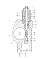
- FIG. 1 is a sectional view showing a configuration of a motor unit 1 using an electric motor according to an embodiment of the present invention.
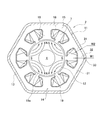
- FIG. 2 is a sectional view showing a configuration of an electric motor used in the motor unit of FIG. It is.
- a motor unit 1 in FIG. 1 includes an electric motor 2 (hereinafter abbreviated as a motor 2) and a speed reduction mechanism (transmission mechanism) 3.
- the rotation of the rotating shaft 4 of the motor 2 is shifted within the speed reduction mechanism unit 3 and is output from the output shaft 5 to the outside of the unit.
- the motor 2 is a brushless motor, and is composed of a stator 11 and a rotor 12 rotatably disposed in the stator 11 as shown in FIGS.
- the stator 11 includes a bottomed cylindrical motor housing 13 and a stator core 14 fixed to the inner surface of the motor housing 13.
- the stator core 14 is formed by laminating a plurality of plates made of a magnetic material, and has an annular outer peripheral portion 15 and teeth protruding from the outer peripheral portion 15 toward the center direction (radially inner side) ( Teeth portion) 16.
- the teeth 16 are formed radially toward the rotor 12.
- a slot 17 is provided between adjacent teeth 16, and the motor 2 has a 6-slot configuration.
- a winding 18 is wound around the outer periphery of the tooth 16. The winding 18 is accommodated in the slot 17.
- the outer periphery 15 of the stator core 14 has a hexagonal shape (polygonal shape).
- the term “annular” in the present invention means not only an annular shape but also a polygonal contour shape.
- the outer peripheral portion 15 includes a straight straight portion 31 and an intermediate portion 32 provided between adjacent straight portions.
- the straight portion 31 is formed integrally with the tooth 16 on the base portion (radially outer peripheral side) of the tooth 16.
- the intermediate part 32 is provided between the teeth 16 so as to connect the adjacent straight parts 31 to each other.
- the straight portion 31 is provided perpendicular to the teeth 16.
- the intermediate portion 32 has a bent portion 33 bent in a “dog leg” shape along the circumferential direction (rotor rotation direction).
- the straight portion 31 and the intermediate portion 32 are connected without a break, and the outer peripheral portion 15 is integrally formed without dividing the entire periphery.
- a rotor 12 is inserted inside the stator 11.
- the rotor 12 includes a rotating shaft 4 and a magnet 19 fixed to the rotating shaft 4.
- One end side of the rotating shaft 4 is rotatably supported by a bearing 21 provided at the end of the motor housing 13.
- the magnet 19 is a rare earth permanent magnet such as neodymium, dysprosium, or samarium.
- the magnet 19 is magnetized to 4 poles, and the motor 2 is a brushless motor having a 4 pole 6 slot configuration.
- the speed reduction mechanism unit 3 includes a worm (driving gear) 5 formed on the rotating shaft 4 and a worm wheel (driven gear) 6 that meshes with the worm 5.
- the speed reduction mechanism unit 3 is accommodated in a gear case 22 formed of synthetic resin or aluminum die casting. As shown in FIG. 1, one end opening side of the motor housing 13 is fixed to the gear case 22.
- the rotating shaft 4 of the motor 2 extends into the gear case 22.
- the rotary shaft 4 is rotatably supported by a bearing 23 and a bearing 24 provided in the gear case 22.
- the worm wheel 7 is fixed to the output shaft 5.
- the output shaft 5 rotates together with the worm wheel 7.
- the cross-sectional outer shape (outer shape of the cross section perpendicular to the rotating shaft 4) of the stator core 14 is a polygonal shape (in this embodiment, a hexagon).
- a polygonal stator when used, stress concentrates on an intermediate portion between adjacent teeth because of its structure. Therefore, the most stress is generated in the intermediate portion (particularly the bent portion) with respect to the electromagnetic excitation force that causes vibration and noise. With respect to the excitation force, the higher the strength of the stator, the more the operation noise can be suppressed. In the case of a polygonal stator, increasing the strength of the intermediate portion is effective as a countermeasure against vibration and noise.
- the thickness dimension W1 of the intermediate portion 32 is set larger than the thickness dimension W2 of the straight portion 31 (W1> W2).
- the greater the thickness dimension W1 of the intermediate portion 32 the greater the strength.
- the size of the stator also increases, and the motor becomes larger and heavier.
- the inventors changed the dimensional ratio of the straight part and the intermediate part in the polygonal stator core to change the radial electromagnetic excitation force teeth 16. , The stator mass, and the winding area (the area that can accommodate the winding in one slot) were compared.
- the stress is reduced as a whole by increasing the dimension W1 of the intermediate portion 32 and increasing the dimension ratio W1 / W2. Therefore, from the viewpoint of stress, it is desirable that the dimensional ratio W1 / W2 between the straight portion 31 and the intermediate portion 32 is as large as possible. That is, in relation to the stator core mass and the winding area, it is desirable that the dimensional ratio W1 / W2 is small, and in relation to stress, it is desirable that the dimensional ratio W1 / W2 is large, and the two are in a trade-off relationship. is there.
- the dimensional ratio W1 / W2 is preferably in the range of 1.25 to 1.5, and particularly around 1.25. Is preferred.
- the stator core strength is suppressed while suppressing the increase in the stator core mass and the decrease in the winding area. It becomes possible to improve. That is, with this setting, it is possible to satisfactorily satisfy three of the stator core mass, the winding area, and the stator core strength with a good balance. As a result, in an electric motor including a stator having a polygonal cross-sectional outer shape, vibration and noise can be effectively reduced without using a resin mold for the stator.
- the present invention is not limited to the above-described embodiment, and various modifications can be made without departing from the scope of the invention.
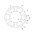
- the stator core 14 having the bent intermediate portion 32 has been described as an example, but the stator core 34 in which a portion of the intermediate portion 32 has a straight shape as shown in FIG.
- the present invention is applicable.
- the bent portions 35 are formed at both ends of the intermediate portion 32 along the circumferential direction (rotor rotation direction), and stress concentrates on the portions.
- stator core mass, winding area, and stator core strength are balanced by setting the dimensional ratio W1 / W2 between the straight portion 31 and the intermediate portion 32 within the range of 1.25 to 1.5 as described above. It can be satisfactorily satisfied.
- the number of slots of the stator 11 is not limited to six, and the present invention can be applied to motors of three slots, four slots, eight slots, and nine slots. With the difference in the number of slots, the outer shape of the stator core 14 also becomes a polygon such as a triangle, a quadrangle, or an octagon. Furthermore, although the brushless motor was shown as embodiment of this invention, this invention is applicable also to a motor with a brush.
- the motor 2 has an SPM (Surface Permanent Magnet) structure in which the magnet 19 is directly opposed to the stator core 14, an IPM (Interior Permanent Magnet) having a steel rotor core on the rotor side and a magnet embedded therein.
- SPM Surface Permanent Magnet
- IPM Interior Permanent Magnet
- the present invention can also be applied to a motor having a configuration.
- the brushless motor according to the present invention can be widely applied not only to an in-vehicle motor of an automobile but also to an electric motor used for home appliances, industrial machines and the like.
Landscapes
- Engineering & Computer Science (AREA)
- Power Engineering (AREA)
- Iron Core Of Rotating Electric Machines (AREA)
Abstract
ブラシレスモータ2は、断面外形が多角形形状に形成されたステータコア14を備える。ステータコア14は、外周部15とティース16とを備える。外周部15は、ティース16の基部に形成されたストレート部31と、隣接するストレート部31を接続するように設けられた中間部32とを備える。中間部32には、周方向(ロータ回転方向)に沿って屈曲する屈曲部33が形成されている。中間部32の径方向の幅W1は、ストレート部31の径方向の幅W2よりも大きく(W1>W2)、両者の比(W1/W2)は、1.25~1.5に設定されている。
Description
本発明は、電動モータに関し、特に、断面外形が多角形形状に形成されたステータを備える電動モータに関する。
電動モータにおける振動、騒音の発生要因として、ステータに加わる径方向への電磁加振力が知られている。例えば、ステータ振動に起因する放射音は、回転方向成分よりも、径方向成分の方が含まれる割合が大きく、その影響が大きい。そこで、径方向の電磁加振力により発生する振動、騒音を抑制する手段として、従来より、ステータを樹脂モールド等により固めて高強度化する方法が行われており、振動、騒音の低減に効果をあげている。
しかしながら、ステータを樹脂モールド等により固める方法は、製造コストが増加したり、モータ寸法が増大したりするなどの課題があった。このため、電動モータにおいて、ステータを樹脂モールド等することなく、振動、騒音を有効に低減する方法が求められていた。
本発明の電動モータは、ロータと、前記ロータの外側に回転自在に配置され、断面外形が多角形形状に形成されたステータコアを備える電動モータであって、前記ステータコアは、環状に形成された外周部と、該外周部から前記ロータに向かって突出し、前記ロータの回転方向に沿って配置される複数個のティース部と、を備え、前記外周部は、前記ティース部の基部に形成されたストレート部と、隣接する前記ストレート部の間に設けられた中間部と、前記中間部に形成された屈曲部と、を備え、前記中間部の径方向の幅W1は、前記ストレート部の径方向の幅W2よりも大きく設定されている(W1>W2)ことを特徴とする。
本発明にあっては、断面外形が多角形形状に形成されたステータコアを備える電動モータにて、ステータコアのティース部基部にストレート部を形成すると共に、屈曲部を有する中間部を、隣接するストレート部の間を接続するように設ける。そして、中間部の径方向の幅W1を、ストレート部の径方向の幅W2よりも大きく設定する(W1>W2)。これにより、ステータコア強度を向上させることができ、ステータを樹脂モールド等することなく、振動や騒音を有効に低減することが可能になる。
前記電動モータにおいて、前記中間部の径方向の幅W1と、前記ストレート部の径方向の幅W2の比(W1/W2)を1.25~1.5に設定しても良い。この場合、比W1/W2を、好ましくは1.25近傍(例えば、1.3程度)に設定しても良い。これにより、ステータコア質量の増加と巻線面積の低下を抑えつつ、ステータコア強度を向上させることができる。その結果、ステータコア質量、巻線面積、ステータコア強度の3つをバランス良く好適に満たしつつ、振動や騒音を有効に低減することが可能になる。
また、前記電動モータに、前記ティース部に巻装され、前記ティース部間に形成されるスロット内に収容される巻線を設け、前記ステータコア質量の増加と前記スロット内における巻線面積の低下を抑えつつ、前記中間部の応力が低く抑えられるよう、前記中間部の径方向の幅W1と、前記ストレート部の径方向の幅W2の比(W1/W2)を、1.25~1.5に設定しても良い。
本発明の電動モータによれば、断面外形が多角形形状に形成されたステータコアを備える電動モータにて、ステータコアの外周部に、ティース部の基部に形成されたストレート部と、隣接するストレート部の間を接続するように設けられた屈曲部を有する中間部と、を設け、中間部の径方向の幅W1を、ストレート部の径方向の幅W2よりも大きく(W1>W2)設定したので、ステータコア強度を向上させることができ、ステータを樹脂モールド等することなく、振動や騒音を有効に低減することが可能になる。
以下、本発明の実施の形態を図面に基づいて詳細に説明する。以下の実施形態の目的は、断面外形が多角形形状のステータを備える電動モータにおいて、ステータを樹脂モールド等することなく、振動や騒音を有効に低減することにある。
図1は、本発明の一実施の形態である電動モータを用いたモータユニット1の構成を示す断面図、図2は、図1のモータユニットに使用されている電動モータの構成を示す断面図である。図1のモータユニット1は、電動モータ2(以下、モータ2と略記する)と、減速機構部(変速機構)3とから構成されており、例えば、自動車のサンルーフやワイパ装置、パワーウインド、パワーシートなどの駆動源として使用される。モータユニット1では、モータ2の回転軸4の回転は減速機構部3内にて変速され、出力軸5からユニット外に出力される。
モータ2はブラシレスモータであり、図1,2に示すように、ステータ11と、ステータ11内に回転自在に配置されたロータ12とから構成されている。ステータ11は、有底筒状のモータハウジング13と、モータハウジング13の内面に固定されたステータコア14を備えている。ステータコア14は、磁性体にて形成されたプレートを複数枚積層して形成されており、環状の外周部15と、外周部15から中心方向(径方向内側)に向かって突設されたティース(ティース部)16とから構成されている。ティース16はロータ12に向かって放射状に形成されており、モータ2では、ティース16はロータ回転方向に沿って6個設けられている。隣接するティース16の間はスロット17となっており、モータ2は6スロット構成となっている。ティース16の外周には巻線18が巻装されている。巻線18は、スロット17内に収容されている。
図2に示すように、ステータコア14の外周部15は、外形が六角形(多角形状)となっている。なお、本発明における環状とは、円環状のみならず、多角形の輪郭形状も含む意味である。外周部15は、直線状のストレート部31と、隣接するストレート部の間に設けられた中間部32とを備えている。ストレート部31は、ティース16の基部(径方向外周側)に、ティース16と一体に形成されている。中間部32は、隣接するストレート部31同士を接続するようにティース16の間に設けられている。ストレート部31は、ティース16に対し垂直に設けられている。中間部32は、周方向(ロータ回転方向)に沿って「ドッグレッグ」状に屈曲した屈曲部33を有している。ストレート部31と中間部32は切れ目なくつながっており、外周部15は、全周が分割されることなく一体に形成されている。
ステータ11の内側にはロータ12が挿入されている。ロータ12は、回転軸4と、回転軸4に固定されたマグネット19とを備えている。回転軸4の一端側は、モータハウジング13の端部に設けられた軸受21によって回転自在に支持されている。マグネット19には、ネオジウムや、ジスプロシウム、サマリウムなどの希土類系の永久磁石が用いられている。マグネット19は4極に着磁されており、モータ2は、4極6スロット構成のブラシレスモータとなっている。
減速機構部3は、回転軸4に形成されたウォーム(駆動ギヤ)5と、ウォーム5と噛合するウォームホイール(被動ギヤ)6とから構成されている。減速機構部3は、合成樹脂やアルミダイカストにて形成されたギヤケース22内に収容されている。図1に示すように、ギヤケース22には、モータハウジング13の一端開口側が固定されている。モータ2の回転軸4は、ギヤケース22内に延伸している。回転軸4は、共にギヤケース22内に設けられたベアリング23と軸受24によって回転自在に支持されている。ウォームホイール7は、出力軸5に固定されている。出力軸5は、ウォームホイール7と共に回転する。
ここで、モータ2は、前述のように、ステータコア14の断面外形(回転軸4に垂直な断面の外形形状)が多角形状(本実施形態では六角形)となっている。一般に、多角形状のステータを用いた場合、その構造上、隣接するティース間の中間部に応力が集中する。したがって、振動や騒音の原因となる電磁加振力に対し、最も応力が生じるのも中間部(特に屈曲部)となる。加振力に対しては、ステータの強度が高い方が作動音を抑制でき、多角形状のステータの場合、中間部の強度を増すことが振動や騒音の対策として有効となる。
そこで、本発明によるモータ2では、中間部32の強度を高くするため、中間部32の厚み寸法W1が、ストレート部31の厚み寸法W2よりも大きく設定されている(W1>W2)。この場合、中間部32の厚み寸法W1は、大きければ大きいほど、その強度は大きくなる。しかしながら、強度が増す反面、ステータのサイズも大きくなり、モータが大型化、重量化する。このため、発明者らは、ストレート部31と中間部32の最適寸法を得るべく、多角形状のステータコアにおいて、ストレート部と中間部の寸法比率を変化させて、径方向の電磁加振力ティース16に生じる応力と、ステータ質量、巻線面積(1スロット内において巻線を収容可能な面積)を比較した。
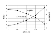
図3,4は、断面外形が六角形のステータコア14において、ストレート部31と中間部32の寸法比(中間部/ストレート部=W1/W2)と、ステータ質量および巻線面積(図3)、屈曲部33の応力(図4)との関係を示すグラフである。図3から分かるように、中間部32の寸法W1を増加させ、寸法比W1/W2を大きくすると、ステータコア14の質量が増加し、巻線面積も低下するが、これらの変化は二次曲線となる傾向がある。このことから、寸法比W1/W2は、なるべく小さい方が望ましいことが分かる。
次に、ステータコア14に掛かる応力の傾向を見ると、図4から分かるように、中間部32の寸法W1を増加させ、寸法比W1/W2を大きくすることで、全体的に応力が低下する。このことから、応力の観点では、ストレート部31と中間部32の寸法比W1/W2は、なるべく大きい方が望ましい。すなわち、ステータコア質量および巻線面積との関係では、寸法比W1/W2は小さい方が望ましく、応力との関係では寸法比W1/W2は大きい方が望ましくなっており、両者はトレードオフの関係にある。
一方、図4を見ると、ストレート部31と中間部32の寸法比W1/W2が1.5~1.75の範囲では、中間部32に発生する応力に余り変化がなく、その低下幅が小さい。また、ストレート部31の応力は直線状に低下するのに対し、中間部32の応力は、1.0~1.5にかけて低下の割合が大きい。W1/W2=1.25のときの中間部32の応力は同=1.0の場合に対し半減しており、3MPaを下回っている。さらに、ストレート部31と中間部32、ティース16の応力は、W1/W2=1.125付近でほぼ等しくなり、1.25近傍では各値が比較的近い値となっている。
そこで、トレードオフの関係にあるステータコア質量および巻線面積と応力をバランス良く調整すべく、上述の関係を総合すると、次のことが分かる。すなわち、ステータコア質量を抑え、巻線面積を確保しつつ、中間部32の応力を低くするには、寸法比W1/W2が1.25~1.5の範囲が好ましく、特に、1.25近傍が好適である。
このように、ストレート部31と中間部32の寸法比W1/W2を、1.25~1.5の範囲に設定することにより、ステータコア質量の増加と巻線面積の低下を抑えつつ、ステータコア強度を向上させることが可能になる。すなわち、かかる設定により、ステータコア質量、巻線面積、ステータコア強度の3つをバランス良く好適に満たすことが可能となる。その結果、断面外形が多角形形状のステータを備える電動モータにおいて、ステータを樹脂モールド等することなく、振動や騒音を有効に低減することが可能になる。
本発明は前記実施形態に限定されるものではなく、その要旨を逸脱しない範囲で種々変更可能であることは言うまでもない。
例えば、前述の実施形態では、屈曲形状となった中間部32を有するステータコア14を例に挙げて説明したが、図5のように中間部32の一部がストレート形状となったステータコア34にも本発明は適用可能である。その場合、中間部32の両端に、屈曲部35が周方向(ロータ回転方向)に沿って屈曲形成され、その部位に応力が集中する。しかし、この場合も、ストレート部31と中間部32の寸法比W1/W2を、前述同様、1.25~1.5の範囲に設定することにより、ステータコア質量、巻線面積、ステータコア強度をバランス良く好適に満たすことができる。
例えば、前述の実施形態では、屈曲形状となった中間部32を有するステータコア14を例に挙げて説明したが、図5のように中間部32の一部がストレート形状となったステータコア34にも本発明は適用可能である。その場合、中間部32の両端に、屈曲部35が周方向(ロータ回転方向)に沿って屈曲形成され、その部位に応力が集中する。しかし、この場合も、ストレート部31と中間部32の寸法比W1/W2を、前述同様、1.25~1.5の範囲に設定することにより、ステータコア質量、巻線面積、ステータコア強度をバランス良く好適に満たすことができる。
また、ステータ11のスロット数も6個には限定されず、3スロット、4スロット、8スロット、9スロットのモータにも本発明は適用可能である。なお、スロット数の違いに伴い、ステータコア14の外形も三角形や四角形、八角形などの多角形となる。さらに、本発明の実施形態としてブラシレスモータを示したが、本発明はブラシ付きモータにも適用可能である。
加えて、モータ2では、マグネット19をステータコア14に直接対向させるSPM(Surface Permanent Magnet)構成としたが、ロータ側に鋼製のロータコアを設け、その内側にマグネットを埋設したIPM(Interior Permanent Magnet)構成のモータにも本発明は適用可能である。
本発明によるブラシレスモータは、自動車の車載モータのみならず、家電製品や産業機械等に使用される電動モータにも広く適用可能である。
1 モータユニット 2 ブラシレスモータ
3 減速機構部 4 回転軸
5 出力軸 6 ウォーム(駆動ギヤ)
7 ウォームホイール(被動ギヤ) 11 ステータ
12 ロータ 13 モータハウジング
14 ステータコア 15 外周部
16 ティース(ティース部) 17 スロット
18 巻線
18U,18V,18W 巻線
19 マグネット 19a マグネット外周面
21 軸受 22 ギヤケース
23 ベアリング 24 軸受
31 ストレート部 32 中間部
33 屈曲部 34 ステータコア
35 屈曲部 W1 中間部幅寸法
W2 ストレート部幅寸法
3 減速機構部 4 回転軸
5 出力軸 6 ウォーム(駆動ギヤ)
7 ウォームホイール(被動ギヤ) 11 ステータ
12 ロータ 13 モータハウジング
14 ステータコア 15 外周部
16 ティース(ティース部) 17 スロット
18 巻線
18U,18V,18W 巻線
19 マグネット 19a マグネット外周面
21 軸受 22 ギヤケース
23 ベアリング 24 軸受
31 ストレート部 32 中間部
33 屈曲部 34 ステータコア
35 屈曲部 W1 中間部幅寸法
W2 ストレート部幅寸法
Claims (3)
- ロータと、
前記ロータの外側に回転自在に配置され、断面外形が多角形形状に形成されたステータコアを備える電動モータであって、
前記ステータコアは、環状に形成された外周部と、該外周部から前記ロータに向かって突出し、前記ロータの回転方向に沿って配置される複数個のティース部と、を備え、
前記外周部は、前記ティース部の基部に形成されたストレート部と、隣接する前記ストレート部の間に設けられた中間部と、前記中間部に形成された屈曲部と、を備え、
前記中間部の径方向の幅W1は、前記ストレート部の径方向の幅W2よりも大きく設定されている(W1>W2)ことを特徴とする電動モータ。 - 請求項1記載の電動モータにおいて、
前記中間部の径方向の幅W1と、前記ストレート部の径方向の幅W2の比(W1/W2)が、1.25~1.5に設定されていることを特徴とする電動モータ。 - 請求項1記載の電動モータにおいて、
前記電動モータは、前記ティース部に巻装され、前記ティース部間に形成されるスロット内に収容される巻線を有し、
前記ステータコア質量の増加と前記スロット内における巻線面積の低下を抑えつつ、前記中間部の応力が低く抑えられるよう、前記中間部の径方向の幅W1と、前記ストレート部の径方向の幅W2の比(W1/W2)が、1.25~1.5に設定されていることを特徴とする電動モータ。
Priority Applications (1)
| Application Number | Priority Date | Filing Date | Title |
|---|---|---|---|
| EP19776809.6A EP3780341A4 (en) | 2018-03-27 | 2019-02-15 | Electric motor |
Applications Claiming Priority (2)
| Application Number | Priority Date | Filing Date | Title |
|---|---|---|---|
| JP2018-059289 | 2018-03-27 | ||
| JP2018059289A JP2019176542A (ja) | 2018-03-27 | 2018-03-27 | 電動モータ |
Publications (1)
| Publication Number | Publication Date |
|---|---|
| WO2019187752A1 true WO2019187752A1 (ja) | 2019-10-03 |
Family
ID=68058020
Family Applications (1)
| Application Number | Title | Priority Date | Filing Date |
|---|---|---|---|
| PCT/JP2019/005545 Ceased WO2019187752A1 (ja) | 2018-03-27 | 2019-02-15 | 電動モータ |
Country Status (3)
| Country | Link |
|---|---|
| EP (1) | EP3780341A4 (ja) |
| JP (1) | JP2019176542A (ja) |
| WO (1) | WO2019187752A1 (ja) |
Cited By (1)
| Publication number | Priority date | Publication date | Assignee | Title |
|---|---|---|---|---|
| CN114825681A (zh) * | 2021-01-27 | 2022-07-29 | 莱克电气股份有限公司 | 电机与毛发护理器具 |
Families Citing this family (2)
| Publication number | Priority date | Publication date | Assignee | Title |
|---|---|---|---|---|
| JP7121071B2 (ja) * | 2020-05-22 | 2022-08-17 | 富士電機株式会社 | 回転電機 |
| CN111884367A (zh) * | 2020-08-31 | 2020-11-03 | 广东肇庆爱龙威机电有限公司 | 无刷直流电机 |
Citations (8)
| Publication number | Priority date | Publication date | Assignee | Title |
|---|---|---|---|---|
| JPS6132753U (ja) * | 1984-07-26 | 1986-02-27 | 三菱電機株式会社 | 直流機 |
| JPS6142237A (ja) * | 1984-07-31 | 1986-02-28 | Matsushita Electric Ind Co Ltd | ステツプモ−タ |
| JPS61134650U (ja) * | 1985-02-05 | 1986-08-22 | ||
| JPH03159531A (ja) * | 1989-08-21 | 1991-07-09 | Switched Reluctance Drives Ltd | レラクタンス回転機 |
| JP2003259572A (ja) * | 2002-02-27 | 2003-09-12 | Minebea Co Ltd | 回転電機 |
| JP2013066313A (ja) * | 2011-09-19 | 2013-04-11 | Nippon Densan Corp | モータおよびモータの製造方法 |
| JP2016021822A (ja) | 2014-07-15 | 2016-02-04 | 株式会社ミツバ | ブラシレスモータ |
| JP2017135861A (ja) * | 2016-01-28 | 2017-08-03 | 日本電産サンキョー株式会社 | ステータおよびステータの製造方法 |
Family Cites Families (2)
| Publication number | Priority date | Publication date | Assignee | Title |
|---|---|---|---|---|
| JP2009106047A (ja) * | 2007-10-23 | 2009-05-14 | Hitachi Ltd | 電動機およびそれを備えた車両駆動装置 |
| DE202016104036U1 (de) * | 2015-08-07 | 2016-10-26 | Johnson Electric S.A. | Kühlgerät |
-
2018
- 2018-03-27 JP JP2018059289A patent/JP2019176542A/ja active Pending
-
2019
- 2019-02-15 WO PCT/JP2019/005545 patent/WO2019187752A1/ja not_active Ceased
- 2019-02-15 EP EP19776809.6A patent/EP3780341A4/en active Pending
Patent Citations (8)
| Publication number | Priority date | Publication date | Assignee | Title |
|---|---|---|---|---|
| JPS6132753U (ja) * | 1984-07-26 | 1986-02-27 | 三菱電機株式会社 | 直流機 |
| JPS6142237A (ja) * | 1984-07-31 | 1986-02-28 | Matsushita Electric Ind Co Ltd | ステツプモ−タ |
| JPS61134650U (ja) * | 1985-02-05 | 1986-08-22 | ||
| JPH03159531A (ja) * | 1989-08-21 | 1991-07-09 | Switched Reluctance Drives Ltd | レラクタンス回転機 |
| JP2003259572A (ja) * | 2002-02-27 | 2003-09-12 | Minebea Co Ltd | 回転電機 |
| JP2013066313A (ja) * | 2011-09-19 | 2013-04-11 | Nippon Densan Corp | モータおよびモータの製造方法 |
| JP2016021822A (ja) | 2014-07-15 | 2016-02-04 | 株式会社ミツバ | ブラシレスモータ |
| JP2017135861A (ja) * | 2016-01-28 | 2017-08-03 | 日本電産サンキョー株式会社 | ステータおよびステータの製造方法 |
Non-Patent Citations (1)
| Title |
|---|
| See also references of EP3780341A4 |
Cited By (2)
| Publication number | Priority date | Publication date | Assignee | Title |
|---|---|---|---|---|
| CN114825681A (zh) * | 2021-01-27 | 2022-07-29 | 莱克电气股份有限公司 | 电机与毛发护理器具 |
| CN114825681B (zh) * | 2021-01-27 | 2026-01-02 | 莱克电气股份有限公司 | 电机与毛发护理器具 |
Also Published As
| Publication number | Publication date |
|---|---|
| JP2019176542A (ja) | 2019-10-10 |
| EP3780341A1 (en) | 2021-02-17 |
| EP3780341A4 (en) | 2021-12-29 |
Similar Documents
| Publication | Publication Date | Title |
|---|---|---|
| JP3691345B2 (ja) | 永久磁石型電動機 | |
| JP4670871B2 (ja) | モータ | |
| CN103339829B (zh) | 无刷电动机以及搭载该无刷电动机的电气设备 | |
| US8796896B2 (en) | Electric motor | |
| EP2527098B1 (en) | Electric power tool | |
| US10693330B2 (en) | Electric motor | |
| KR20150078467A (ko) | 매입형 영구자석 모터의 회전자 | |
| WO2017119431A1 (ja) | 回転電動機 | |
| JP2003018810A (ja) | 外部回転子を備えた電機 | |
| JP2008099418A (ja) | 永久磁石埋込型電動機 | |
| JP2015104180A (ja) | 回転電機の回転子 | |
| WO2019187752A1 (ja) | 電動モータ | |
| JP5634338B2 (ja) | 磁石モータ及び磁石モータを備えたドラム式洗濯機 | |
| JP4569632B2 (ja) | モータ | |
| KR101103363B1 (ko) | 스테이터 및 이를 구비한 모터 | |
| KR20170092882A (ko) | 코깅토크를 저감한 전동기 | |
| WO2019198464A1 (ja) | モータ及びブラシレスワイパーモータ | |
| KR101757542B1 (ko) | 차량용 전기 모터 | |
| WO2019235096A1 (ja) | ブラシレスモータ | |
| WO2017042886A1 (ja) | 永久磁石式回転電動機およびこれを用いた圧縮機 | |
| KR20200014040A (ko) | 토크리플 감소를 위한 노치구조의 전동기 | |
| JP2012039714A (ja) | ハウジングリング、及びモータ、並びに電動パワーステアリング装置 | |
| JP2019161782A (ja) | 電動モータ | |
| JP6914150B2 (ja) | ブラシレスモータ | |
| JP2019161783A (ja) | ブラシレスモータ |
Legal Events
| Date | Code | Title | Description |
|---|---|---|---|
| 121 | Ep: the epo has been informed by wipo that ep was designated in this application |
Ref document number: 19776809 Country of ref document: EP Kind code of ref document: A1 |
|
| NENP | Non-entry into the national phase |
Ref country code: DE |
|
| ENP | Entry into the national phase |
Ref document number: 2019776809 Country of ref document: EP Effective date: 20201027 |