WO2019187937A1 - 障害物検知システム、及び、作業車両 - Google Patents
障害物検知システム、及び、作業車両 Download PDFInfo
- Publication number
- WO2019187937A1 WO2019187937A1 PCT/JP2019/007682 JP2019007682W WO2019187937A1 WO 2019187937 A1 WO2019187937 A1 WO 2019187937A1 JP 2019007682 W JP2019007682 W JP 2019007682W WO 2019187937 A1 WO2019187937 A1 WO 2019187937A1
- Authority
- WO
- WIPO (PCT)
- Prior art keywords
- range
- measurement
- masking
- obstacle
- unit
- Prior art date
- Legal status (The legal status is an assumption and is not a legal conclusion. Google has not performed a legal analysis and makes no representation as to the accuracy of the status listed.)
- Ceased
Links
Images










Classifications
-
- G—PHYSICS
- G01—MEASURING; TESTING
- G01S—RADIO DIRECTION-FINDING; RADIO NAVIGATION; DETERMINING DISTANCE OR VELOCITY BY USE OF RADIO WAVES; LOCATING OR PRESENCE-DETECTING BY USE OF THE REFLECTION OR RERADIATION OF RADIO WAVES; ANALOGOUS ARRANGEMENTS USING OTHER WAVES
- G01S17/00—Systems using the reflection or reradiation of electromagnetic waves other than radio waves, e.g. lidar systems
- G01S17/88—Lidar systems specially adapted for specific applications
- G01S17/89—Lidar systems specially adapted for specific applications for mapping or imaging
-
- G—PHYSICS
- G01—MEASURING; TESTING
- G01S—RADIO DIRECTION-FINDING; RADIO NAVIGATION; DETERMINING DISTANCE OR VELOCITY BY USE OF RADIO WAVES; LOCATING OR PRESENCE-DETECTING BY USE OF THE REFLECTION OR RERADIATION OF RADIO WAVES; ANALOGOUS ARRANGEMENTS USING OTHER WAVES
- G01S15/00—Systems using the reflection or reradiation of acoustic waves, e.g. sonar systems
- G01S15/88—Sonar systems specially adapted for specific applications
- G01S15/93—Sonar systems specially adapted for specific applications for anti-collision purposes
- G01S15/931—Sonar systems specially adapted for specific applications for anti-collision purposes of land vehicles
-
- A—HUMAN NECESSITIES
- A01—AGRICULTURE; FORESTRY; ANIMAL HUSBANDRY; HUNTING; TRAPPING; FISHING
- A01B—SOIL WORKING IN AGRICULTURE OR FORESTRY; PARTS, DETAILS, OR ACCESSORIES OF AGRICULTURAL MACHINES OR IMPLEMENTS, IN GENERAL
- A01B69/00—Steering of agricultural machines or implements; Guiding agricultural machines or implements on a desired track
-
- G—PHYSICS
- G01—MEASURING; TESTING
- G01S—RADIO DIRECTION-FINDING; RADIO NAVIGATION; DETERMINING DISTANCE OR VELOCITY BY USE OF RADIO WAVES; LOCATING OR PRESENCE-DETECTING BY USE OF THE REFLECTION OR RERADIATION OF RADIO WAVES; ANALOGOUS ARRANGEMENTS USING OTHER WAVES
- G01S15/00—Systems using the reflection or reradiation of acoustic waves, e.g. sonar systems
- G01S15/02—Systems using the reflection or reradiation of acoustic waves, e.g. sonar systems using reflection of acoustic waves
- G01S15/04—Systems determining presence of a target
-
- G—PHYSICS
- G01—MEASURING; TESTING
- G01S—RADIO DIRECTION-FINDING; RADIO NAVIGATION; DETERMINING DISTANCE OR VELOCITY BY USE OF RADIO WAVES; LOCATING OR PRESENCE-DETECTING BY USE OF THE REFLECTION OR RERADIATION OF RADIO WAVES; ANALOGOUS ARRANGEMENTS USING OTHER WAVES
- G01S15/00—Systems using the reflection or reradiation of acoustic waves, e.g. sonar systems
- G01S15/86—Combinations of sonar systems with lidar systems; Combinations of sonar systems with systems not using wave reflection
-
- G—PHYSICS
- G01—MEASURING; TESTING
- G01S—RADIO DIRECTION-FINDING; RADIO NAVIGATION; DETERMINING DISTANCE OR VELOCITY BY USE OF RADIO WAVES; LOCATING OR PRESENCE-DETECTING BY USE OF THE REFLECTION OR RERADIATION OF RADIO WAVES; ANALOGOUS ARRANGEMENTS USING OTHER WAVES
- G01S15/00—Systems using the reflection or reradiation of acoustic waves, e.g. sonar systems
- G01S15/87—Combinations of sonar systems
-
- G—PHYSICS
- G01—MEASURING; TESTING
- G01S—RADIO DIRECTION-FINDING; RADIO NAVIGATION; DETERMINING DISTANCE OR VELOCITY BY USE OF RADIO WAVES; LOCATING OR PRESENCE-DETECTING BY USE OF THE REFLECTION OR RERADIATION OF RADIO WAVES; ANALOGOUS ARRANGEMENTS USING OTHER WAVES
- G01S15/00—Systems using the reflection or reradiation of acoustic waves, e.g. sonar systems
- G01S15/88—Sonar systems specially adapted for specific applications
- G01S15/89—Sonar systems specially adapted for specific applications for mapping or imaging
-
- G—PHYSICS
- G01—MEASURING; TESTING
- G01S—RADIO DIRECTION-FINDING; RADIO NAVIGATION; DETERMINING DISTANCE OR VELOCITY BY USE OF RADIO WAVES; LOCATING OR PRESENCE-DETECTING BY USE OF THE REFLECTION OR RERADIATION OF RADIO WAVES; ANALOGOUS ARRANGEMENTS USING OTHER WAVES
- G01S17/00—Systems using the reflection or reradiation of electromagnetic waves other than radio waves, e.g. lidar systems
- G01S17/02—Systems using the reflection of electromagnetic waves other than radio waves
- G01S17/04—Systems determining the presence of a target
-
- G—PHYSICS
- G01—MEASURING; TESTING
- G01S—RADIO DIRECTION-FINDING; RADIO NAVIGATION; DETERMINING DISTANCE OR VELOCITY BY USE OF RADIO WAVES; LOCATING OR PRESENCE-DETECTING BY USE OF THE REFLECTION OR RERADIATION OF RADIO WAVES; ANALOGOUS ARRANGEMENTS USING OTHER WAVES
- G01S17/00—Systems using the reflection or reradiation of electromagnetic waves other than radio waves, e.g. lidar systems
- G01S17/02—Systems using the reflection of electromagnetic waves other than radio waves
- G01S17/06—Systems determining position data of a target
- G01S17/42—Simultaneous measurement of distance and other co-ordinates
-
- G—PHYSICS
- G01—MEASURING; TESTING
- G01S—RADIO DIRECTION-FINDING; RADIO NAVIGATION; DETERMINING DISTANCE OR VELOCITY BY USE OF RADIO WAVES; LOCATING OR PRESENCE-DETECTING BY USE OF THE REFLECTION OR RERADIATION OF RADIO WAVES; ANALOGOUS ARRANGEMENTS USING OTHER WAVES
- G01S17/00—Systems using the reflection or reradiation of electromagnetic waves other than radio waves, e.g. lidar systems
- G01S17/86—Combinations of lidar systems with systems other than lidar, radar or sonar, e.g. with direction finders
-
- G—PHYSICS
- G01—MEASURING; TESTING
- G01S—RADIO DIRECTION-FINDING; RADIO NAVIGATION; DETERMINING DISTANCE OR VELOCITY BY USE OF RADIO WAVES; LOCATING OR PRESENCE-DETECTING BY USE OF THE REFLECTION OR RERADIATION OF RADIO WAVES; ANALOGOUS ARRANGEMENTS USING OTHER WAVES
- G01S17/00—Systems using the reflection or reradiation of electromagnetic waves other than radio waves, e.g. lidar systems
- G01S17/87—Combinations of systems using electromagnetic waves other than radio waves
-
- G—PHYSICS
- G01—MEASURING; TESTING
- G01S—RADIO DIRECTION-FINDING; RADIO NAVIGATION; DETERMINING DISTANCE OR VELOCITY BY USE OF RADIO WAVES; LOCATING OR PRESENCE-DETECTING BY USE OF THE REFLECTION OR RERADIATION OF RADIO WAVES; ANALOGOUS ARRANGEMENTS USING OTHER WAVES
- G01S17/00—Systems using the reflection or reradiation of electromagnetic waves other than radio waves, e.g. lidar systems
- G01S17/88—Lidar systems specially adapted for specific applications
- G01S17/93—Lidar systems specially adapted for specific applications for anti-collision purposes
- G01S17/931—Lidar systems specially adapted for specific applications for anti-collision purposes of land vehicles
-
- G—PHYSICS
- G01—MEASURING; TESTING
- G01S—RADIO DIRECTION-FINDING; RADIO NAVIGATION; DETERMINING DISTANCE OR VELOCITY BY USE OF RADIO WAVES; LOCATING OR PRESENCE-DETECTING BY USE OF THE REFLECTION OR RERADIATION OF RADIO WAVES; ANALOGOUS ARRANGEMENTS USING OTHER WAVES
- G01S7/00—Details of systems according to groups G01S13/00, G01S15/00, G01S17/00
- G01S7/48—Details of systems according to groups G01S13/00, G01S15/00, G01S17/00 of systems according to group G01S17/00
- G01S7/481—Constructional features, e.g. arrangements of optical elements
- G01S7/4811—Constructional features, e.g. arrangements of optical elements common to transmitter and receiver
- G01S7/4813—Housing arrangements
-
- G—PHYSICS
- G01—MEASURING; TESTING
- G01S—RADIO DIRECTION-FINDING; RADIO NAVIGATION; DETERMINING DISTANCE OR VELOCITY BY USE OF RADIO WAVES; LOCATING OR PRESENCE-DETECTING BY USE OF THE REFLECTION OR RERADIATION OF RADIO WAVES; ANALOGOUS ARRANGEMENTS USING OTHER WAVES
- G01S7/00—Details of systems according to groups G01S13/00, G01S15/00, G01S17/00
- G01S7/48—Details of systems according to groups G01S13/00, G01S15/00, G01S17/00 of systems according to group G01S17/00
- G01S7/497—Means for monitoring or calibrating
-
- G—PHYSICS
- G01—MEASURING; TESTING
- G01S—RADIO DIRECTION-FINDING; RADIO NAVIGATION; DETERMINING DISTANCE OR VELOCITY BY USE OF RADIO WAVES; LOCATING OR PRESENCE-DETECTING BY USE OF THE REFLECTION OR RERADIATION OF RADIO WAVES; ANALOGOUS ARRANGEMENTS USING OTHER WAVES
- G01S7/00—Details of systems according to groups G01S13/00, G01S15/00, G01S17/00
- G01S7/52—Details of systems according to groups G01S13/00, G01S15/00, G01S17/00 of systems according to group G01S15/00
- G01S7/52017—Details of systems according to groups G01S13/00, G01S15/00, G01S17/00 of systems according to group G01S15/00 particularly adapted to short-range imaging
- G01S7/5205—Means for monitoring or calibrating
-
- G—PHYSICS
- G05—CONTROLLING; REGULATING
- G05D—SYSTEMS FOR CONTROLLING OR REGULATING NON-ELECTRIC VARIABLES
- G05D1/00—Control of position, course, altitude or attitude of land, water, air or space vehicles, e.g. using automatic pilots
- G05D1/02—Control of position or course in two dimensions
-
- G—PHYSICS
- G05—CONTROLLING; REGULATING
- G05D—SYSTEMS FOR CONTROLLING OR REGULATING NON-ELECTRIC VARIABLES
- G05D1/00—Control of position, course, altitude or attitude of land, water, air or space vehicles, e.g. using automatic pilots
- G05D1/02—Control of position or course in two dimensions
- G05D1/021—Control of position or course in two dimensions specially adapted to land vehicles
- G05D1/0231—Control of position or course in two dimensions specially adapted to land vehicles using optical position detecting means
- G05D1/0238—Control of position or course in two dimensions specially adapted to land vehicles using optical position detecting means using obstacle or wall sensors
- G05D1/024—Control of position or course in two dimensions specially adapted to land vehicles using optical position detecting means using obstacle or wall sensors in combination with a laser
-
- G—PHYSICS
- G05—CONTROLLING; REGULATING
- G05D—SYSTEMS FOR CONTROLLING OR REGULATING NON-ELECTRIC VARIABLES
- G05D2111/00—Details of signals used for control of position, course, altitude or attitude of land, water, air or space vehicles
- G05D2111/10—Optical signals
- G05D2111/17—Coherent light, e.g. laser signals
-
- G—PHYSICS
- G05—CONTROLLING; REGULATING
- G05D—SYSTEMS FOR CONTROLLING OR REGULATING NON-ELECTRIC VARIABLES
- G05D2111/00—Details of signals used for control of position, course, altitude or attitude of land, water, air or space vehicles
- G05D2111/20—Acoustic signals, e.g. ultrasonic signals
Definitions
- the present invention relates to an obstacle detection system used for a work vehicle, and a work vehicle provided with a position information measurement sensor that measures position information related to a measurement object around the work vehicle.
- a distance sensor for measuring the distance to the measurement object is attached to the work vehicle, and the measurement object within a predetermined distance is detected based on the measurement information of the distance sensor. Obstacle detection processing is detected. In the obstacle detection processing, when an obstacle is detected, collision avoidance control such as operating a notification buzzer is performed (see, for example, Patent Document 1).
- members provided in the work vehicle such as a lifting ladder may be arranged around the work vehicle. Therefore, if a member or the like provided in the work vehicle enters the measurement range of the distance sensor, the member or the like provided in the work vehicle may be erroneously detected as an obstacle.
- Patent Literature 1 masking that limits the execution of the collision avoidance control without detecting an obstacle as a range in which a member or the like included in the work vehicle enters among the measurement range of the distance sensor. It is set as a range. This prevents erroneous detection of a member or the like provided in the work vehicle as an obstacle.
- the work vehicle as described above is provided with a camera as a position information measurement sensor, detects a work position such as an excavation position or a grazing position based on imaging information of the camera, moves the work vehicle to the work position, and moves to a predetermined position.
- a camera as a position information measurement sensor, detects a work position such as an excavation position or a grazing position based on imaging information of the camera, moves the work vehicle to the work position, and moves to a predetermined position.
- the work vehicle described in Patent Document 2 is calibrated so that the installation state of the position information measurement sensor (camera) becomes a desired state. Attaching the calibration jig to the work equipment (bucket) of the work vehicle and imaging the calibration jig with the camera detects the deviation between the camera installation position and installation direction and the desired installation position and installation direction.
- the camera installation state is calibrated to the desired state.
- the camera is imaged by the camera, and the characteristic points of the bucket itself, such as the tip of the bucket claw and the edge of the bucket, are extracted, so that the camera installation state is It is described that it can be calibrated to a desired state.
- the work vehicle is provided with not only members arranged at a fixed position such as an elevating ladder, but also a movable part such as a traveling part such as a steerable wheel and a work device. Even when the movable part enters the measurement range of the distance sensor, as described above, it is necessary to set a masking range so that the movable part is not erroneously detected as an obstacle.
- the masking range is set for the movable part, it is difficult to set what range as the masking range because the movable part moves relative to the work vehicle. If a large range including a movable part is set as a masking range, a range where detection as an obstacle cannot be performed becomes large. Conversely, if the masking range is reduced, it is possible to suppress an increase in the range in which detection as an obstacle cannot be performed, but there is a high possibility that the movable part is erroneously detected as an obstacle.
- an object of the present invention is to provide an obstacle detection system capable of preventing erroneous detection of a movable part as an obstacle while suppressing an increase in the range in which detection as an obstacle cannot be performed. It is in.
- the calibration jig is attached to the bucket of the work vehicle and the position information measurement sensor is calibrated, but not only the work of attaching the calibration jig to the bucket.
- the work to remove the calibration jig from the bucket must also be performed. Therefore, time-consuming work is required and work efficiency is reduced.
- the bucket is used only for calibration, and the bucket is a dedicated member for calibration.
- work related to the position information measurement sensor it is conceivable to perform not only calibration but also other work. Therefore, for example, it is desired to improve work efficiency by using the member used for calibration for other work.
- the problem of the present invention is that the member used for calibration is also used for other purposes and the work efficiency is improved, and the position information measurement sensor is not only calibrated but also other work. It is in the point which provides the work vehicle which can also be performed.
- the working device Since the working device has different sizes such as height, width, and length depending on the type, the working device that enters the measurement range of the distance sensor is different. Thus, for example, in order to prevent all types of work devices from being erroneously detected as obstacles, a large range may be set as the masking range. However, if the masking range is set to a large range, the range in which no obstacle is detected becomes large. Conversely, if the masking range is reduced, it is possible to prevent the range in which no obstacle is detected from increasing, but it is difficult to prevent all types of work devices from being erroneously detected as obstacles. Thus, when setting a masking range for a work device having a plurality of types, it is difficult to set what range as a masking range.
- an object of the present invention is to provide an obstacle detection system capable of preventing erroneous detection of a work device as an obstacle while suppressing an increase in the range in which no obstacle is detected. It is in.
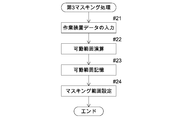
- a first characteristic configuration of the present invention is provided in a work vehicle, and a distance sensor capable of measuring a distance to a measurement object; Based on the measurement result of the distance sensor, when a measurement object within a predetermined distance is detected as an obstacle, an obstacle control unit that performs collision avoidance control, Without performing detection as an obstacle, a masking range setting unit that sets a masking range that limits the execution of collision avoidance control by the obstacle control unit;
- a movable range acquisition unit that acquires a movable range of a movable unit that is movably provided in the work vehicle;
- the masking range setting unit is that a masking range is set according to the movable range acquired by the movable range acquiring unit.
- the masking range setting unit sets the masking range according to the movable range acquired by the movable range acquisition unit. can do. Therefore, the masking range can be set to a range suitable for the movable part including the movable range of the movable part without being too large or too small with respect to the movable range of the movable part. As a result, the masking range can be set appropriately for the movable part, so that it is possible to prevent the movable part from being erroneously detected as an obstacle while suppressing the increase in the range where the obstacle cannot be detected. it can.
- a working device that is movably connected to the work vehicle is provided as the movable portion, and the movable range acquisition unit has a movable range when the working device is actually moved. It is in the point to get.
- the movable range acquisition unit acquires the movable range when the working device is actually moved, an accurate movable range of the working device when actually performing work on the working device is obtained. Can be acquired.
- the masking range setting unit can appropriately set the masking range according to the work on the actual working device, and thus can more appropriately suppress the increase of the range where the obstacle cannot be detected. However, it is possible to more appropriately prevent erroneous detection of the movable part as an obstacle.
- the third characteristic configuration of the present invention is that the masking range setting unit changes and sets the masking range according to the movable state of the working device.
- the masking range setting part changes and sets the masking range according to the movable state of the working device.
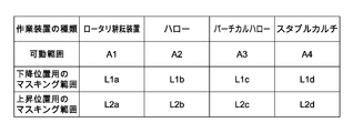
- the fourth characteristic configuration of the present invention is provided with a storage unit that stores type / movable range information in which the type of the working device and the movable range acquired by the movable range acquisition unit are associated with each other.
- the masking range setting unit is that the masking range is set according to the type of the working device actually connected to the work vehicle and the type / movable range information stored in the storage unit. .
- storage part has memorize
- the masking range setting unit can acquire the type of the working device that is actually connected to the work vehicle, the masking range setting unit acquires the movable range associated with the type of the working device from the type / movable range information stored in the storage unit, and the movable range. Accordingly, a masking range suitable for the working device can be set. Thereby, for example, the user can set a masking range suitable for the work device simply by inputting the type of the work device actually connected to the work vehicle. Can be achieved.
- the fifth characteristic configuration of the present invention is that an external output unit is provided that can output the type / movable range information stored in the storage unit to the outside through communication with the outside.
- the external output unit can output the type / movable range information stored in the storage unit to an external management device, other work vehicle, or the like by communication with the outside.
- a masking range in another work vehicle can be set.
- the type / movable range information is acquired, for example, the user or the like simply inputs the type of the work device to be connected to the other work vehicle, and the work can be performed on the other work vehicle.
- a masking range suitable for the apparatus can be set.
- the type / movable range information is shared information shared by a plurality of work vehicles, and the masking range of the plurality of work vehicles can be easily set using the shared information.
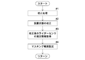
- a sixth characteristic configuration of the present invention includes a position information measurement sensor that measures position information related to a measurement object around the work vehicle main body, A calibration processing unit for performing a calibration process for calibrating the installation state of the position information measurement sensor in the work vehicle main body to a desired state; A masking range setting unit that sets a masking range that excludes measurement of position information out of the measurement range of the position information measurement sensor;
- the position information measurement sensor is arranged in a state where a part of the work vehicle main body or a member provided in the work vehicle main body is included in a measurement range,
- the calibration processing unit calibrates using the work vehicle body included in the measurement range of the position information measurement sensor or a part of the member provided in the work vehicle body based on the measurement information of the position information measurement sensor.
- the masking range setting unit includes the work vehicle body included in the measurement range of the position information measurement sensor based on the measurement information of the position information measurement sensor after the installation state of the position information measurement sensor is calibrated to a desired state.
- the masking range is set by using a part of the members provided in the work vehicle main body.
- the calibration processing unit performs the calibration process, so that the position information measurement sensor In the measurement range, the user or the like can grasp where the work vehicle main body or a part of the member included in the work vehicle main body exists. Since the work vehicle main body or a part of the member included in the work vehicle main body is located at the predetermined position, the user or the like is positioned from the predetermined position where the work vehicle main body or a part of the member included in the work vehicle main body exists. It is possible to determine whether or not there is a deviation and the amount of positional deviation.
- a user or the like can adjust the installation state (installation position, installation direction, etc.) of the position information measurement sensor to perform calibration so that the installation state of the position information measurement sensor is a desired state.
- the work vehicle main body or a part of the member provided in the work vehicle main body is used for the calibration of the position information measurement sensor, for example, it is necessary to attach and remove the calibration jig to the work vehicle main body or the like. There is no problem and the labor can be reduced.
- the masking range setting unit is included in the work vehicle main body or the work vehicle main body in the measurement range of the position information measurement sensor.
- a range corresponding to the provided member is set as a masking range.
- the masking range setting unit can acquire accurate position information from the measurement information of the position information measurement sensor after calibration, and sets an appropriate masking range using the work vehicle body or a member provided on the work vehicle body. can do.
- the work vehicle body or the member provided on the work vehicle body can be used not only for calibration of the position information measurement sensor but also for setting the masking range of the position information measurement sensor.
- the position information measurement sensor can be calibrated and the masking range of the position information measurement sensor can be set while effectively improving the work efficiency by effectively utilizing the members provided in the work vehicle main body.
- the position information measurement sensor is a first position information measurement sensor arranged in a state where a part of a member included in the work vehicle main body or the work vehicle main body is included in a measurement range; And a plurality of second position information measurement sensors arranged in a state where a part of the work vehicle main body or a member provided in the work vehicle main body is not included in the measurement range, A calibration jig that can be arranged in a state included in the measurement range of the second position information measurement sensor is provided, The calibration processing unit is configured to perform a calibration process using the calibration jig included in the measurement range of the second position information measurement sensor based on the measurement information of the second position information measurement sensor.
- the work vehicle main body includes not only the first position information measurement sensor arranged in a state where a part of the work vehicle main body or a member included in the work vehicle main body is included in the measurement range, but also the work vehicle main body or the work vehicle main body.
- a second position information measurement sensor arranged in a state where a part of the member to be arranged is not included in the measurement range is also provided.
- the calibration processing unit cannot perform the calibration process using the work vehicle main body or a part of the members provided in the work vehicle main body.
- the calibration processing unit can perform the calibration process using the calibration jig included in the measurement range of the second position information measurement sensor, and can appropriately perform the calibration of the second position information measurement sensor.
- the eighth characteristic configuration of the present invention is that the calibration jig is configured to be detachable from the work vehicle main body.
- the calibration processing unit can perform an appropriate calibration process using the calibration jig included in the measurement range of the second position information measurement sensor, and accurately calibrate the second position information measurement sensor. Can do.
- the position information measurement sensor is configured by a distance sensor that measures the distance to the measurement object in three dimensions as position information. Based on the measurement information of the distance sensor, an obstacle detection unit that detects a measurement object within a predetermined distance as an obstacle is provided, The masking range setting unit lies in that a range in which the obstacle detection unit does not detect an obstacle is set as the masking range.
- the obstacle detection unit When the work vehicle main body or a part of the member included in the work vehicle main body is included in the measurement range of the distance sensor, the obstacle detection unit obstructs the work vehicle main body or a part of the member included in the work vehicle main body. There is a possibility of false detection as an object. Therefore, according to this configuration, the masking range setting unit sets the range in which the obstacle detection unit does not detect the obstacle as the masking range. Thus, the obstacle can be detected while preventing the work vehicle main body or a part of the member included in the work vehicle main body from being erroneously detected as an obstacle. The work vehicle main body can be run while avoiding the collision.
- a tenth characteristic configuration of the present invention is provided in a work vehicle, and a distance sensor capable of measuring a distance to a measurement object; Based on the measurement result of the distance sensor, when a measurement object within a predetermined distance is detected as an obstacle, an obstacle control unit that performs collision avoidance control, Without performing detection as an obstacle, a masking range setting unit that sets a masking range that limits the execution of collision avoidance control by the obstacle control unit; A storage unit that stores type / movable range information that associates the type of the work device with the movable range for the work device that is connectable to the work vehicle, The masking range setting unit is that the masking range is set according to the type of work device actually connected to the work vehicle and the type / movable range information stored in the storage unit.
- storage part has memorize
- the masking range setting unit can specify the movable range corresponding to the work device from the type / movable range information stored in the storage unit only by acquiring the type of the work device actually connected to the work vehicle.
- a masking range can be set according to the specified movable range. Thereby, for example, the user can set a masking range suitable for the work device simply by inputting the type of the work device actually connected to the work vehicle. It is possible to appropriately set the masking range for the work device while achieving the above.
- the eleventh characteristic configuration of the present invention is that the masking range setting unit changes and sets the masking range in accordance with the movable state of the working device.
- the masking range setting part changes and sets the masking range according to the movable state of the working device.
- the masking range setting unit is configured to be able to correct the masking range according to a movable range when the working device connected to the work vehicle is actually moved. is there.
- the masking range setting unit can correct the masking range according to the accurate movable range of the working device when actually working on the working device. It is possible to appropriately set the masking range in accordance with. Accordingly, it is possible to more appropriately prevent the work apparatus from being erroneously detected as an obstacle while appropriately suppressing an increase in the range in which the detection as an obstacle cannot be performed.
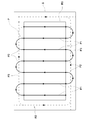
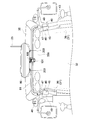
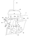
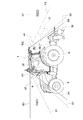
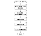
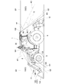
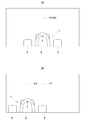
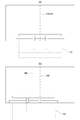
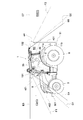
- the figure which shows schematic structure of an automatic traveling system Block diagram showing schematic configuration of automatic driving system Diagram showing the target travel route The figure which shows the upper part part of the tractor in front view The figure which shows the upper part part of a tractor in a rear view The figure which shows the antenna unit and front rider sensor in the use position in a side view
- the perspective view which shows the support structure of an antenna unit and a front rider sensor The figure which shows the antenna unit and front rider sensor in the non-use position in a side view
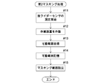
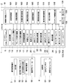
- movement in a 1st masking process The figure which shows the measurement range of a front rider sensor and a rear rider sensor in the side view at the time of connecting a front side working device The figure which shows the three-dimensional image generated from the measurement result of the front rider sensor The flowchart which shows the flow of operation
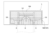
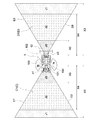
- Block diagram showing schematic configuration of automatic driving system The figure which shows the measurement range of the front rider sensor, the rear rider sensor and the sonar unit in plan view The figure which shows the three-dimensional image produced
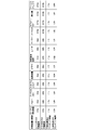
- Table showing type / movable range information The figure which shows the three-dimensional image produced
- FIG. 1 An embodiment when a work vehicle provided with an obstacle detection system according to the present invention is applied to an automatic travel system will be described with reference to the drawings.
- the tractor 1 is applied as a work vehicle.
- a passenger work vehicle such as a riding rice transplanter, a combiner, a riding mower, a wheel loader, a snowplow, etc.
- unmanned work vehicles such as an unmanned mower, can be applied.
- the automatic traveling system includes an automatic traveling unit 2 mounted on the tractor 1 and a mobile communication terminal 3 set to communicate with the automatic traveling unit 2.
- the mobile communication terminal 3 can employ a tablet personal computer, a smartphone, or the like having a display unit 51 (for example, a liquid crystal panel) that can be touch-operated.
- the tractor 1 is provided with a traveling machine body 7 having left and right front wheels 5 functioning as drivable steering wheels and drivable left and right rear wheels 6.
- a bonnet 8 is disposed on the front side of the traveling machine body 7, and an electronically controlled diesel engine (hereinafter referred to as an engine) 9 having a common rail system is provided in the bonnet 8.
- An engine 9 having a common rail system is provided in the bonnet 8.
- a cabin 10 that forms a boarding type driving unit is provided behind the hood 8 of the traveling machine body 7.
- a rotary cultivator which is an example of the working device 12, is connected to the rear portion of the traveling machine body 7 via a three-point link mechanism 11 so as to be movable up and down and rollable so that the tractor 1 can be configured to have a rotary cultivating specification. it can.
- a working device 12 such as a plow, a harrow, a vertical harrow, a stable cultivar, a seeding device, a spraying device, or the like can be connected to the rear portion of the tractor 1.
- the tractor 1 includes an electronically controlled transmission 13 that shifts the power from the engine 9, an all-hydraulic power steering mechanism 14 that steers the left and right front wheels 5, and the left and right rear wheels 6.
- Left and right side brakes (not shown) for braking, an electronically controlled brake operating mechanism 15 that enables hydraulic operation of the left and right side brakes, and a work clutch that intermittently transmits power to the work device 12 such as a rotary tiller (see FIG. (Not shown)
- an electronically controlled clutch operating mechanism 16 that enables hydraulic operation of the work clutch
- an electrohydraulic control type lifting drive mechanism 17 that drives the working device 12 such as a rotary tiller, etc., automatic travel of the tractor 1, etc.
- An in-vehicle electronic control unit 18 having various control programs, a vehicle speed sensor 19 for detecting the vehicle speed of the tractor 1, and a steering angle sensor for detecting the steering angle of the front wheels 5. Sa 20, and the positioning unit 21 and the like for measuring the current position and current heading of the tractor 1 is provided.
- the engine 9 may be an electronically controlled gasoline engine equipped with an electronic governor.
- a hydraulic mechanical continuously variable transmission (HMT), a hydrostatic continuously variable transmission (HST), a belt-type continuously variable transmission, or the like can be employed.
- the power steering mechanism 14 may be an electric power steering mechanism 14 provided with an electric motor.
- the cabin 10 includes a cabin frame 31 that forms a framework of the cabin 10, a front glass 32 that covers the front side, a rear glass 33 that covers the rear side, and an axis around the vertical direction. And a pair of left and right doors 34 (see FIG. 1) that can swing open and close and a roof 35 on the ceiling side.
- the cabin frame 31 includes a pair of left and right front columns 36 disposed at the front end and a pair of left and right rear columns 37 disposed at the rear end.
- front struts 36 are disposed at the left and right corners on the front side
- rear struts 37 are disposed at the left and right corners on the rear side.
- the cabin frame 31 is supported on the traveling machine body 7 via an anti-vibration member such as an elastic body, and anti-vibration measures are taken to prevent vibration from the traveling machine body 7 and the like from being transmitted to the cabin 10.
- an anti-vibration member such as an elastic body
- anti-vibration measures are taken to prevent vibration from the traveling machine body 7 and the like from being transmitted to the cabin 10.
- a cabin 10 is provided.
- a steering wheel 38 that enables manual steering of the left and right front wheels 5 via a power steering mechanism 14 (see FIG. 2), a driver's seat 39 for passengers, a touch panel An expression display unit and various operation tools are provided.
- a boarding / alighting step 41 serving as a boarding / alighting unit for the cabin 10 (driver's seat 39) is provided.
- the on-vehicle electronic control unit 18 includes a shift control unit 181 that controls the operation of the transmission 13, a brake control unit 182 that controls the operation of the left and right side brakes, and a work device 12 such as a rotary tillage device.
- a non-volatile in-vehicle storage unit 185 and the like for storing the route P (for example, see FIG. 3) and the like are included.
- the positioning unit 21 includes a satellite that measures the current position and current direction of the tractor 1 using GPS (Global Positioning System), which is an example of a satellite positioning system (NSS).
- GPS Global Positioning System
- a navigation device 22, an inertial measurement device (IMU) 23 that measures the attitude, orientation, and the like of the tractor 1 by including a three-axis gyroscope and a three-direction acceleration sensor are provided.
- GPS Global Positioning System
- IMU inertial measurement device
- Examples of positioning methods using GPS include DGPS (Differential GPS) and RTK-GPS (Real Time Kinematic GPS).
- RTK-GPS suitable for positioning of a moving body is employed. Therefore, as shown in FIGS. 1 and 2, a reference station 4 that enables positioning by RTK-GPS is installed at a known position around the field.
- Each of the tractor 1 and the reference station 4 includes, as shown in FIG. 2, GPS antennas 24 and 61 that receive radio waves transmitted from the GPS satellite 71 (see FIG. 1), and between the tractor 1 and the reference station 4.
- Communication modules 25, 62, etc. that enable wireless communication of various data (various information) including the positioning data (positioning information) in FIG.
- the satellite navigation device 22 receives the positioning data obtained by the GPS antenna 24 on the tractor side receiving the radio wave from the GPS satellite 71, and the GPS antenna 61 on the base station side receives the radio wave from the GPS satellite 71. Based on the obtained positioning data, the current position and the current direction of the tractor 1 can be measured with high accuracy.
- the positioning unit 21 includes the satellite navigation device 22 and the inertial measurement device 23, thereby measuring the current position, current azimuth, and attitude angle (yaw angle, roll angle, pitch angle) of the tractor 1 with high accuracy. Can do.
- the GPS antenna 24, communication module 25, and inertial measurement device 23 provided in the tractor 1 are housed in an antenna unit 80 as shown in FIG.
- the antenna unit 80 is disposed at an upper position on the front side of the cabin 10.
- the mobile communication terminal 3 includes positioning data between the terminal electronic control unit 52 having various control programs for controlling the operation of the display unit 51 and the like, and the communication module 25 on the tractor side. And a communication module 55 that enables wireless communication of various data including the.
- the terminal electronic control unit 52 includes a travel route generation unit 53 that generates a target travel route P for travel guidance (for example, see FIG. 3) for automatically traveling the tractor 1, and various input data ( Input terminal), a non-volatile terminal storage unit 54 that stores the target travel route P generated by the travel route generation unit 53, and the like.
- a driver or a user such as a driver or the like follows the input information for setting the target travel route displayed on the display unit 51 of the mobile communication terminal 3.
- Car body data such as the type and model of the work device 12 is input, and the input car body data (car body information) is stored in the terminal storage unit 54.
- a travel region S (see FIG. 3) that is a target for generating the target travel route P is used as a field, and the terminal electronic control unit 52 of the mobile communication terminal 3 acquires field data (field information) including the shape and position of the field. Stored in the terminal storage unit 54.
- the terminal electronic control unit 52 determines the shape and position of the field from the current position of the tractor 1 acquired by the positioning unit 21. It is possible to acquire position information for specifying the like.
- the terminal electronic control unit 52 specifies the shape and position of the field from the acquired position information, and acquires field data including the travel region S specified from the specified shape and position of the field.
- FIG. 3 shows an example in which a rectangular traveling area S is specified.
- the travel route generation unit 53 uses the field data and the vehicle body data stored in the terminal storage unit 54, A travel route P is generated.
- the travel route generation unit 53 sets the travel region S into a central region R1 and an outer peripheral region R2.
- the central area R1 is set at the center of the traveling area S, and is a reciprocating work area in which a predetermined operation (for example, work such as tillage) is performed by automatically traveling the tractor 1 in the reciprocating direction in advance.
- the outer peripheral region R2 is set around the central region R1, and is a circular work region in which the tractor 1 automatically travels in the circular direction following the central region R1 and performs a predetermined operation.
- the travel route generating unit 53 uses a turning radius necessary for making the tractor 1 turn on the shore of the field based on the turning radius included in the vehicle body data, the front-rear width, the left-right width, and the like of the tractor 1. Seeking.
- the traveling route generation unit 53 divides the traveling region S into a central region R1 and an outer peripheral region R2 so as to ensure the space obtained on the outer periphery of the central region R1.
- the travel route generation unit 53 generates a target travel route P using vehicle body data, farm field data, and the like.
- the target travel route P includes a plurality of work routes P1 that are arranged in parallel at a constant distance corresponding to the work width and have the same straight traveling distance in the central region R1, and the start ends of the adjacent work routes P1. It has the connection path
- the plurality of work paths P1 are paths for performing predetermined work while causing the tractor 1 to travel straight ahead.
- the connection path P2 is a U-turn path for changing the traveling direction of the tractor 1 by 180 degrees without performing a predetermined work, and connects the end of the work path P1 and the start end of the next adjacent work path P1.
- the circulation path P3 is a path for performing a predetermined operation while the tractor 1 travels around in the outer peripheral region R2.
- the circulatory path P3 switches the traveling direction of the tractor 1 90 degrees by switching the tractor 1 between forward traveling and backward traveling at positions corresponding to the four corners of the traveling region S.
- the target travel route P shown in FIG. 3 is merely an example, and what target travel route is set can be appropriately changed.
- the target travel route P generated by the travel route generation unit 53 can be displayed on the display unit 51 and is stored in the terminal storage unit 54 as route data (route information) associated with vehicle body data, farm field data, and the like.
- the route data includes the azimuth angle of the target travel route P, the set engine rotation speed and the target travel speed set according to the travel mode of the tractor 1 on the target travel route P, and the like.
- the terminal electronic control unit 52 transfers the route data from the mobile communication terminal 3 to the tractor 1, whereby the in-vehicle electronic control unit 18 of the tractor 1.
- route data can be acquired.
- the in-vehicle electronic control unit 18 automatically causes the tractor 1 to travel along the target travel route P while acquiring its current position (current position of the tractor 1) by the positioning unit 21 based on the acquired route data. Can do.
- the current position of the tractor 1 acquired by the positioning unit 21 is transmitted from the tractor 1 to the mobile communication terminal 3 in real time (for example, every several seconds), and the mobile communication terminal 3 grasps the current position of the tractor 1. ing.
- the entire route data can be transferred from the terminal electronic control unit 52 to the in-vehicle electronic control unit 18 at a time before the tractor 1 starts the automatic travel.
- the route data including the target travel route P can be divided into a plurality of route portions for each predetermined distance with a small amount of data.
- only the initial route portion of the route data is transferred from the terminal electronic control unit 52 to the in-vehicle electronic control unit 18 before the tractor 1 starts automatic traveling.
- route data of only the subsequent route portion corresponding to the point is transmitted from the terminal electronic control unit 52 to the on-vehicle electronic control. It may be transferred to the unit 18.
- the user can display the display unit 51 on the mobile communication terminal 3.
- the mobile communication terminal 3 transmits an instruction to start automatic driving to the tractor 1 by instructing start of automatic driving by operating.
- the in-vehicle electronic control unit 18 receives an instruction to start automatic traveling, and the positioning unit 21 obtains its current position (current position of the tractor 1) while obtaining the target traveling route P.
- the automatic traveling control for automatically traveling the tractor 1 is started.
- the in-vehicle electronic control unit 18 performs automatic traveling control for automatically traveling the tractor 1 along the target traveling route P based on the positioning information of the tractor 1 acquired by the positioning unit 21 (corresponding to a satellite positioning system). It is comprised as a traveling control part.
- the automatic travel control includes automatic shift control for automatically controlling the operation of the transmission 13, automatic braking control for automatically controlling the operation of the brake operating mechanism 15, automatic steering control for automatically steering the left and right front wheels 5, and a rotary tillage device.
- the automatic operation control for automatically controlling the operation of the working device 12 is included.
- the shift control unit 181 determines whether the tractor 1 on the target travel route P is based on the route data of the target travel route P including the target travel speed, the output of the positioning unit 21, and the output of the vehicle speed sensor 19.
- the operation of the transmission 13 is automatically controlled so that the target travel speed set according to the travel mode and the like is obtained as the vehicle speed of the tractor 1.
- the braking control unit 182 causes the left and right side brakes to move rearward in the braking area included in the route data of the target traveling route P based on the target traveling route P and the output of the positioning unit 21.
- the operation of the brake operation mechanism 15 is automatically controlled so as to properly brake the wheel 6.
- the steering angle setting unit 184 determines the target of the left and right front wheels 5 based on the route data of the target travel route P and the output of the positioning unit 21 so that the tractor 1 automatically travels on the target travel route P.
- the steering angle is obtained and set, and the set target steering angle is output to the power steering mechanism 14.
- the power steering mechanism 14 Based on the target steering angle and the output of the steering angle sensor 20, the power steering mechanism 14 automatically steers the left and right front wheels 5 so that the target steering angle is obtained as the steering angle of the left and right front wheels 5.
- the work device control unit 183 operates the tractor 1 at the start of the work route P1 (for example, see FIG. 3) based on the route data of the target travel route P and the output of the positioning unit 21.
- a predetermined work for example, tillage work
- the tractor 1 reaches the work end point such as the end of the work path P1 (for example, see FIG. 3).
- the operations of the clutch operation mechanism 16 and the lifting drive mechanism 17 are automatically controlled so that the predetermined work by the work device 12 is stopped.
- the automatic traveling unit 2 is configured by the unit 21, the communication module 25, and the like.
- the tractor 1 can also automatically run while the user or the like gets on the cabin 10. Accordingly, not only the user or the like does not board the cabin 10 but also the tractor 1 can automatically travel along the target travel route P by the automatic traveling control by the in-vehicle electronic control unit 18, and the user or the like can board the cabin 10. Even in this case, the tractor 1 can be automatically driven along the target travel route P by the automatic travel control by the in-vehicle electronic control unit 18.
- the vehicle-mounted electronic control unit 18 switches between an automatic running state in which the tractor 1 is automatically run and a manual running state in which the tractor 1 is run based on the operation of the user or the like. be able to. Therefore, the automatic travel state can be switched from the automatic travel state to the manual travel state during the automatic travel on the target travel route P, and conversely, the manual travel can be performed while the manual travel state is traveling.
- the state can be switched to the automatic running state.
- a switching operation unit for switching between the automatic driving state and the manual driving state can be provided in the vicinity of the driver's seat 39, and the switching operation unit is carried around. It can also be displayed on the display unit 51 of the communication terminal 3. Further, when the user operates the steering wheel 38 during the automatic traveling control by the in-vehicle electronic control unit 18, the automatic traveling state can be switched to the manual traveling state.
- the tractor 1 is provided with an obstacle detection system 100 for detecting an obstacle around the tractor 1 (the traveling machine body 7) and avoiding a collision with the obstacle.
- the obstacle detection system 100 includes a plurality of rider sensors (corresponding to distance sensors) 101 and 102 that can measure a distance to a measurement object in three dimensions using a laser, and an ultrasonic wave to the measurement object.
- Sonar units 103 and 104 having a plurality of sonars capable of measuring distances and an obstacle control unit 107 are provided.
- the measurement object to be measured by the rider sensors 101 and 102 and the sonar units 103 and 104 is an object or a person.
- the obstacle control unit 107 performs obstacle detection processing for detecting an object to be measured such as an object or a person within a predetermined distance as an obstacle based on the measurement information of the rider sensors 101 and 102 and the sonar units 103 and 104. In the obstacle detection process, when an obstacle is detected, collision avoidance control is performed. The obstacle control unit 107 repeatedly performs obstacle detection processing based on the measurement information of the rider sensors 101 and 102 and the sonar units 103 and 104 in real time, appropriately detects obstacles such as objects and people, and detects the obstacles. Collision avoidance control is performed to avoid collision with objects.
- the obstacle control unit 107 is provided in the in-vehicle electronic control unit 18.
- the in-vehicle electronic control unit 18 is connected to the engine electronic control unit, the rider sensors 101 and 102, the sonar units 103 and 104, and the like included in the common rail system through a CAN (ControllerCAArea ⁇ Network). ing.
- the rider sensors 101 and 102 measure the distance from the round-trip time until the laser beam (for example, pulsed near-infrared laser beam) bounces off the measurement object to the measurement object (Time Of Flight). .
- the rider sensors 101 and 102 scan the laser beam at high speed in the vertical and horizontal directions at a high speed, and sequentially measure the distance to the measurement object at each scanning angle, so that the distance to the measurement object is three-dimensionally. Measuring.
- the rider sensors 101 and 102 repeatedly measure the distance to the measurement object within the measurement range in real time.
- the rider sensors 101 and 102 are configured to be able to generate a three-dimensional image from the measurement result and output it to the outside.
- the three-dimensional image generated from the measurement results (measurement information) of the rider sensors 101 and 102 is displayed on a display device such as the display unit of the tractor 1 or the display unit 51 of the mobile communication terminal 3 so that the user or the like The presence or absence can be visually recognized.
- a display device such as the display unit of the tractor 1 or the display unit 51 of the mobile communication terminal 3 so that the user or the like
- the presence or absence can be visually recognized.
- the distance in the perspective direction can be shown using color or the like.
- a sensor 101 and a rear rider sensor 102 used for detecting an obstacle on the rear side of the tractor 1 with the rear side of the tractor 1 (the traveling machine body 7) as a measurement range D are provided.
- the front rider sensor 101 and the rear rider sensor 102 will be described below.
- the support structure of the front rider sensor 101, the support structure of the rear rider sensor 102, the measurement range C of the front rider sensor 101, and the measurement range D of the rear rider sensor 102 are described below. These will be described in order.
- a support structure for the front rider sensor 101 will be described. As shown in FIGS. 1 and 7, the front rider sensor 101 is attached to the bottom of the antenna unit 80 disposed at the upper position on the front side of the cabin 10. First, the support structure of the antenna unit 80 will be described. Next, a structure for attaching the front rider sensor 101 to the bottom of the antenna unit 80 will be described.
- the antenna unit 80 is attached to a pipe-shaped antenna unit support stay 81 that extends over the entire length of the cabin 10 in the left-right direction of the traveling machine body 7.
- the antenna unit 80 is disposed at a position corresponding to the central portion of the cabin 10 in the left-right direction of the traveling machine body 7.
- the antenna unit support stay 81 is fixedly connected in a state extending over the left and right mirror mounting portions 45 located on the left and right oblique front sides of the cabin 10.
- the mirror mounting portion 45 includes a mirror mounting base material 46 fixed to the front support column 36, a mirror mounting bracket 47 fixed to the mirror mounting base material 46, and a hinge portion 49 provided on the mirror mounting bracket 47. , And a mirror mounting arm 48 that is rotatable.
- the antenna unit support stay 81 is formed in a bridge shape in which left and right end portions are curved downward.
- the left and right ends of the antenna unit support stay 81 are fixedly connected to the upper end side portion of the mirror mounting bracket 47 via the first mounting plate 201.
- a horizontal mounting surface is formed on the upper end portion of the mirror mounting bracket 47, and a horizontal mounting surface is also formed on the lower end portion of the first mounting plate 201.
- the antenna unit support stay 81 is fixedly connected in a posture extending in the horizontal direction by being fastened by a connecting tool 50 such as a bolt and nut in a state in which both mounting surfaces are superposed on each other. Since the antenna unit 80 is supported by the front column 36 constituting the cabin frame 31 via the antenna unit support stay 81 and the mirror mounting portion 45, the antenna unit 80 is prevented from transmitting vibration to the antenna unit 80 and the like. The unit 80 is firmly supported.
- the mounting structure of the antenna unit 80 to the antenna unit support stay 81 is the second mounting plate 202 fixed to the antenna unit 80 side and the second mounting plate 202 fixed to the antenna unit support stay 81 side.
- the antenna unit 80 is attached to the antenna unit support stay 81 by fastening the 3 attachment plate 203 with a connector 50 such as a bolt and nut.
- a pair of left and right second mounting plates 202 are provided in the left-right direction of the traveling machine body 7 at a predetermined interval.
- the second mounting plate 202 is configured by a plate-like body bent in an L shape having a stay side mounting portion 202b extending downward from an outer end portion of the unit side mounting portion 202a extending in the left-right direction.
- the second mounting plate 202 is mounted in such a manner that the unit side mounting portion 202a is fixedly connected to the bottom portion of the antenna unit 80 by the connector 50 or the like, and the stay side mounting portion 202b extends downward.
- a pair of front and rear circular holes for connection by a connector or the like is formed in the stay side mounting portion 202b of the second mounting plate 202.
- the third mounting plate 203 is configured by an L-shaped plate-like body in which the front side portion extends below the rear side portion. Similarly to the second mounting plate 202, the third mounting plate 203 is provided as a pair on the left and right sides with a predetermined interval in the left-right direction of the traveling machine body 7.
- the third attachment plate 203 is attached in such a manner that the lower end edge of the rear part is fixedly connected to the upper part of the antenna unit support stay 81 by welding or the like, and the front part is located on the front side of the antenna unit support stay 81.
- the third mounting plate 203 is formed with a long elongated hole 203a extending along the front-rear direction of the traveling machine body 7 from the front side portion to the rear side portion, and a connecting round hole on the lower side of the front side portion. 203b is formed.
- the antenna unit 80 When the antenna unit 80 is attached to the antenna unit support stay 81, as shown in FIGS. 6 and 7, the antenna unit 80 is disposed above the antenna unit support stay 81, and the antenna of the communication module 25 is placed upward. It is located in the use position extending to the side.
- the second mounting plate 202 is connected to the third mounting plate 202 so that the front and rear round holes of the stay mounting portion 202b of the second mounting plate 202 are aligned with the front end and the rear end of the elongated hole 203a of the third mounting plate 203.
- the second mounting plate 202 and the third mounting plate 203 are overlapped with each other while being positioned on the inner side of the mounting plate 203.
- the coupling unit 50 is inserted and fastened across the round holes before and after the second mounting plate 202 and the long holes 203a of the third mounting plate 203, so that the antenna unit 80 is attached to the antenna unit support stay 81 at the use position. Can be attached.
- locations corresponding to the front end portion and the rear end portion of the long hole 203a are set as connection locations by the connector 50, and in each of the pair of left and right second mounting plates 202 and third mounting plates 203.
- a total of four locations including the front portion and the rear portion are connected portions by the connector 50.
- the antenna unit 80 is located not only at the use position, but also at the front side of the antenna unit support stay 81 as shown in FIG.
- the antenna unit support stay 81 can be attached to the antenna unit support stay 81 even in a non-use position extending to the position.
- the antenna unit 80 When the antenna unit 80 is attached to the antenna unit support stay 81 in the non-use position, as shown in FIG. 8, the antenna unit 80 is located in the non-use position and the second attachment plate 202 has a stay side attachment portion 202b.
- the second mounting plate 202 In a state in which the second mounting plate 202 is positioned inward of the third mounting plate 203 so that the front and rear circular holes are aligned with the front end portions of the circular holes 203b and the long holes 203a of the third mounting plate 203.
- the second mounting plate 202 and the third mounting plate 203 are overlapped.
- the connecting tool 50 is inserted through the front round hole in the stay side mounting portion 202b of the second mounting plate 202 and the round hole 203b in the third mounting plate 203, and the rear of the second mounting plate 202 in the stay side mounting portion 202b.
- the antenna unit 80 can be attached to the antenna unit support stay 81 at the non-use position by inserting and fastening the connector 50 across the side round hole and the front side end of the long hole 203a.
- the antenna unit 80 when the antenna unit 80 is changed from the use position (see FIG. 6) to the non-use position (see FIG. 8), as shown in FIG. 6, the front end of the long hole 203a of the third mounting plate 203 is used.
- the connecting tool 50 located at the rear is removed, the connecting tool 50 located at the rear end of the long hole 203a of the third mounting plate 203 is loosened, and the state where the connecting tool 50 is inserted into the long hole 203a is maintained.
- the antenna unit 80 By moving the connector 50 forward along the long hole 203a from the rear side end to the front side end, the antenna unit 80 is suspended downwardly with the connector 50 as a pivot shaft. As shown in FIG. 8, the position of the antenna unit 80 is changed to the non-use position.
- the connecting tool 50 is inserted through the round hole on the front side of the second mounting plate 202 and the round hole 203b on the third mounting plate 203, and the front side of the round hole on the rear side of the second mounting plate 202 and the long hole 203a.
- the connector 50 can be inserted and fastened over the side end portion, and the antenna unit 80 can be repositioned from the use position to the non-use position.
- the antenna unit 80 In a state where the antenna unit 80 is attached at the use position, as shown in FIG. 9A, a part of the antenna unit 80 protrudes upward from the highest level line Z passing through the highest part 35a of the roof 35.
- the antenna of the communication module 25 can be arranged on the upper side so that the wireless communication of the communication module 25 can be performed appropriately.
- the antenna unit 80 when the antenna unit 80 is attached at the non-use position, the upper end of the antenna unit 80 is located at the same height position as the highest level line Z or the highest level line Z as shown in FIG. Is also placed at a low position.
- the antenna unit 80 does not protrude above the highest level line Z, and the antenna unit 80 becomes an obstacle. Further, it is possible to prevent the antenna unit 80 from being damaged due to contact with an obstacle or the like.
- the mounting structure of the front rider sensor 101 to the antenna unit 80 is fastened by a connecting tool 50 such as a bolt and nut via a fourth mounting plate 204 and a fifth mounting plate 205, thereby A sensor 101 is attached to the bottom of the antenna unit 80.
- the fourth mounting plate 204 has a mounting surface portion 204a extending in the left-right direction, and is formed in a bridge shape in which both end portions of the mounting surface portion 204a extend downward.
- the fifth mounting plate 205 has a pair of left and right mounting surface portions 205a facing each other in the left-right direction, and is formed in a bridge shape in which upper end portions of the mounting surface portions 205a are connected to each other.
- the mounting surface portion 204 a of the fourth mounting plate 204 is fixedly connected to the bottom portion of the antenna unit 80 by the connector 50.
- a front side portion of the fourth mounting plate 204 and a rear side portion of the fifth mounting plate 205 are fixedly connected by the connector 50.
- a pair of left and right mounting surface portions 205 a of the fifth mounting plate 205 are fixedly connected to both lateral side portions of the front rider sensor 101 by the connector 50.
- the front rider sensor 101 is attached so as to be sandwiched between the left and right attachment surface portions 205a of the fifth attachment plate 205 in the left-right direction.
- the front rider sensor 101 is configured to be detachable from the antenna unit 80 via a fourth mounting plate 204 and a fifth mounting plate 205.
- the front rider sensor 101 can be retrofitted, and only the front rider sensor 101 can be removed.
- the antenna unit 80 is also detachably attached to the mirror attachment portion 45 via the antenna unit support stay 81, the front rider sensor 101 is attached to and detached from the traveling machine body 7 by the front rider sensor 101 alone. And can be attached to and detached from the traveling machine body 7 together with the antenna unit 80.
- the front rider sensor 101 uses an antenna unit support stay 81 and the like that support the antenna unit 80 as a common support stay, and, like the antenna unit 80, prevents transmission of vibration to the front rider sensor 101. Strongly supported.
- the front rider sensor 101 is provided integrally with the antenna unit 80, by changing the position of the antenna unit 80 between the use position and the non-use position, as shown in FIG. However, as shown in FIG. 8, the use position that is used for obstacle detection on the front side of the traveling machine body 7 and the non-use position that is not used for obstacle detection as shown in FIG. The position can be changed freely.
- the front rider sensor 101 When the front rider sensor 101 is located at the use position, as shown in FIGS. 6 and 9A, the front rider sensor 101 serves as a boarding / alighting portion for the cabin 10 (driver's seat 39) in the vertical direction. It is disposed at a position higher than 41 (see FIG. 1) and at a position corresponding to the roof 35.
- the front rider sensor 101 is attached in a front lowering posture that is located on the lower side as the front side portion is located.
- the front rider sensor 101 is provided to measure in a state where the front side of the traveling machine body 7 is looked down obliquely from the upper side.
- the front rider sensor 101 is disposed in the vicinity of the front obliquely upper side with respect to the front end portion 35 b of the roof 35 using the lower space of the antenna unit 80.
- at least a part of the front rider sensor 101 overlaps with the front end portion 35 b of the roof 35 from the line of sight of the passenger T sitting on the driver's seat 39.
- the arrangement position of the front rider sensor 101 is a position where at least a part of the front rider sensor 101 is hidden at the front end portion 35 b of the roof 35.
- the front rider sensor 101 exists in a position where a part of the front rider sensor 101 deviates from the visible range B1 on the front side of the occupant T seated in the driver's seat 39. Can be prevented from being blocked.
- the position of the front rider sensor 101 is arranged at the center in the left-right direction of the antenna unit 80 in the left-right direction of the traveling machine body 7. Since the antenna unit 80 is disposed at a position corresponding to the central portion of the cabin 10 in the left-right direction of the traveling aircraft body 7, the front rider sensor 101 is also a position corresponding to the central portion of the cabin 10 in the lateral direction of the traveling aircraft body 7. Is arranged.
- a front camera 108 whose imaging range is the front side of the traveling machine body 7 is attached to the fifth mounting plate 205 by a connector or the like.
- the front camera 108 is disposed above the front rider sensor 101. Similar to the front rider sensor 101, the front camera 108 is attached in a front-down posture that is located on the lower side as the front side portion is located.
- the front camera 108 is provided so as to take an image in a state where the front side of the traveling machine body 7 is looked down obliquely from above.
- a captured image captured by the front camera 108 can be output to the outside.
- the captured image of the front camera 108 can be displayed on a display device such as the display unit of the tractor 1 or the display unit 51 of the mobile communication terminal 3 so that a user or the like can visually recognize the situation around the tractor 1.
- the rear rider sensor 102 is attached to a pipe-like sensor support stay 301 over the entire length of the cabin 10 in the left-right direction of the traveling machine body 7.
- the rear rider sensor 102 is disposed at a position corresponding to the central portion of the cabin 10 in the left-right direction of the traveling machine body 7.
- the sensor support stay 301 is fixedly connected in a state extending over the left and right rear columns 37 located at the left and right ends of the cabin 10.
- the sensor support stay 301 is formed in a bridge shape in a plan view in which the left and right ends are curved obliquely forward.
- the left and right end portions of the sensor support stay 301 are fixedly connected to attachment members provided at upper end portions of the left and right rear columns 37 via a sixth attachment plate 206.
- a sixth mounting plate 206 is fixedly connected to the left and right ends of the sensor support stay 301 by welding or the like.
- the sensor support stay 301 is fixedly connected in a posture extending in the horizontal direction by fastening the sixth mounting plate 206 and a mounting member provided at an upper end side portion of the rear column 37 with the connecting tool 50.
- the rear rider sensor 102 is attached to the sensor support stay 301 via a seventh attachment plate 207 and an eighth attachment plate 208 as shown in FIG. .
- the seventh mounting plate 207 has a pair of left and right side wall surface portions 207a facing each other in the left and right direction, and is formed in a bridge shape in which upper end portions of the side wall surface portions 207a are connected to each other.
- the eighth mounting plate 208 has a pair of left and right mounting surface portions 208a facing each other in the left-right direction, and is formed in a bridge shape in which the upper end portions of the mounting surface portion 208a are connected to each other.
- the lower end edge of the side wall surface portion 207a of the seventh mounting plate 207 is fixedly connected to the sensor support stay 301 by welding or the like.
- the rear part of the seventh mounting plate 207 and the front part of the eighth mounting plate 208 are fixedly connected by the connector 50.
- a pair of left and right mounting surface portions 208 a of the eighth mounting plate 208 are fixedly connected to both lateral side portions of the rear rider sensor 102 by the connector 50.
- the rear rider sensor 102 is attached so as to be sandwiched between the left and right attachment surface portions 208a of the eighth attachment plate 208 in the left-right direction.
- a reinforcing plate 302 is fixedly connected to the front portion of the seventh mounting plate 207 by a connector or the like.
- a front side portion of the reinforcing plate 302 is fixedly connected to the upper surface portion of the roof 35 by a connecting tool 50.
- the reinforcing plate 302 extends in the front-rear direction in a U-shape having an upright wall with both side ends in the left-right direction bent upward, and extends across the roof 35, the seventh mounting plate 207, and the sensor support stay 301. Is provided.
- the rear rider sensor 102 is disposed at a position higher than the getting-on / off step 41 (see FIG. 1) at a position corresponding to the roof 35 in the vertical direction.
- the rear rider sensor 102 is attached to the sensor support stay 301 in a rearwardly lowered posture that is located on the lower side as the rear side portion is located.
- the rear rider sensor 102 is provided so as to perform measurement in a state where the rear side of the traveling machine body 7 is looked down obliquely from above.
- the sensor support stay 301 is disposed in the vicinity of the rear end portion 35c of the roof 35 in the front-rear direction of the traveling machine body 7 and at the position overlapping the rear end portion 35c of the roof 35 in the vertical direction.
- the sensor 102 is disposed at substantially the same height with respect to the rear end portion 35c of the roof 35 or at a position in the vicinity of the rear obliquely upper side. Accordingly, as shown in FIG. 11, at least a part of the rear rider sensor 102 overlaps with the rear end portion 35 c of the roof 35 from the line of sight of the passenger T sitting on the driver's seat 39.
- the rear rider sensor 102 is disposed at a position where at least a part of the rear rider sensor 102 is hidden at the rear end portion 35 c of the roof 35.
- the occupant T seated in the driver's seat 39 is located at a position where a part of the rear rider sensor 102 deviates from the rear viewable range B2, and the view of the occupant T seated in the driver's seat 39 is the rear rider sensor. Blocking at 102 can be suppressed.
- the rear rider sensor 102 is configured to be detachably attached to the rear column 37 via a sensor support stay 301, a seventh attachment plate 207, and an eighth attachment plate 208.
- the rear rider sensor 102 can be retrofitted, and the rear rider sensor 102 can be removed. Since the rear rider sensor 102 is supported by the rear column 37 constituting the cabin frame 31 via the sensor support stay 301, the rear rider sensor 102 is firmly supported while preventing transmission of vibration to the rear rider sensor 102. Yes.
- a rear camera 109 whose imaging range is the rear side of the traveling machine body 7 is attached to the eighth mounting plate 208 by a connector or the like.
- the rear camera 109 is disposed above the rear rider sensor 102. Similar to the rear rider sensor 102, the rear camera 109 is attached in a rear-lowering posture that is located on the lower side as the rear part is located.
- the rear camera 109 is provided so as to take an image in a state where the rear side of the traveling machine body 7 is looked down obliquely from above.
- a captured image captured by the rear camera 109 can be output to the outside.
- the captured image of the rear camera 109 can be displayed on a display device such as the display unit of the tractor 1 or the display unit 51 of the mobile communication terminal 3 so that a user or the like can visually recognize the situation around the tractor 1.
- the measurement range C of the front rider sensor 101 will be described.
- the front rider sensor 101 has a left / right measurement range C1 in the left / right direction, and also has an up / down measurement range C2 in the up / down direction as shown in FIG.
- the front rider sensor 101 has a quadrangular pyramid that is included in the left / right measurement range C1 and the vertical measurement range C2 in the range from the self to the position separated by the first set distance X1 (see FIG. 12).
- a shape measurement range C is set.
- the left-right measurement range C1 in the front rider sensor 101 is a left-right symmetric range with the left-right center line of the traveling machine body 7 as the symmetry axis in the left-right direction of the traveling machine body 7, as shown in FIG.
- the left / right measurement range C1 is set to a range of a first set angle ⁇ 1 between a first boundary line E1 and a second boundary line E2 extending from the front rider sensor 101.
- the front rider sensor 101 has the left / right measurement range C1, but the entire left / right measurement range C1 is not an obstacle detection range, and the center of the left / right measurement range C1 is an obstacle detection range.
- a detection range J for detecting an obstacle is set on the center side in the left-right direction of the traveling machine body 7, and a non-detection range K for detecting no obstacle is set outside the detection range J. ing.
- the range in which the obstacle control unit 107 detects an obstacle in the obstacle detection process based on the measurement information of the front rider sensor 101 is the detection range J in the left-right direction.
- the detection range J is set to a range up to a position separated by a second set distance X2 on both the left and right sides with respect to the central portion of the traveling machine body 7 in the left-right direction of the traveling machine body 7.
- the detection range J is set to be larger than the lateral width of the tractor 1 and the lateral width of the work device 12 in the lateral width direction of the traveling machine body 7.
- the size of the detection range J can be appropriately changed.
- the size of the detection range J can be changed by arbitrarily changing the second set distance X2. .
- the vertical measurement range C2 in the front rider sensor 101 is set to a range of a second set angle ⁇ 2 between the third boundary line E3 and the fourth boundary line E4 extending from the front rider sensor 101.
- the third boundary line E3 is set as a horizontal line extending in the horizontal direction forward from the front rider sensor 101, and the fourth boundary line E4 is based on a first tangent line G1 from the front rider sensor 101 to the front upper portion of the front wheel 5. Is also set to a straight line located on the lower side.
- the vertical measurement range C2 is set so that the first center line F1 between the third boundary line E3 and the fourth boundary line E4 is located above the bonnet 8. A sufficiently large measuring range is secured.
- a measurement object such as an object or a person is positioned near the front end of the traveling machine body 7 (the front end of the bonnet 8). Even if exists, the measurement object can be measured.
- a part of the bonnet 8 and a part of the front wheel 5 enter the vertical measurement range C ⁇ b> 2 in the front rider sensor 101.
- a part of the hood 8 or a part of the front wheel 5 may be erroneously detected as an obstacle. Therefore, a first masking process for preventing the erroneous detection is performed.
- a masking range L in which a part of the hood 8 and a part of the front wheel 5 are present is not detected as an obstacle (see FIG. 13). Is set in advance. This first masking process will be described later.
- the obstacle control unit 107 performs the obstacle detection process based on the measurement information of the front rider sensor 101, so that it is included in the detection range J (see FIG. 12) in the left-right direction and In the range included in the vertical measurement range C2 (see FIG. 11) in the direction, the presence or absence of an obstacle is detected in a range excluding the masking range L.
- the measurement range D of the rear rider sensor 102 will be described. Like the front rider sensor 101, the rear rider sensor 102 has a left / right measurement range D1 in the left / right direction as shown in FIG. 12, and an up / down measurement range D2 in the up / down direction as shown in FIG. Have. As a result, the rear rider sensor 102 has a quadrangular pyramid that is included in the left and right measurement range D1 and the vertical measurement range D2 in the range from the self to the position separated by the third set distance X3 (see FIG. 12). A shape measurement range D is set. Incidentally, X1 and X3 can be set to the same distance or different distances.
- the left and right measurement range D1 in the rear rider sensor 102 is set to a third setting between the fifth boundary line E5 and the sixth boundary line E6 extending from the rear rider sensor 102, as in the front rider sensor 101.
- the angle ⁇ 3 is set in a range.
- a detection range J is set on the center side in the left-right direction of the traveling machine body 7, and a non-detection range K is set outside the detection range J.
- the range in which the obstacle control unit 107 detects an obstacle in the obstacle detection process based on the measurement information of the rear rider sensor 102 is a detection range J in the left-right direction.
- the vertical measurement range D2 in the rear rider sensor 102 is set to a range of a fourth set angle ⁇ 4 between the seventh boundary line E7 and the eighth boundary line E8 extending from the rear rider sensor 102.
- the working device 12 is provided so as to freely move up and down between the raised position and the lowered position, in FIG. 11, the working device 12 located at the lowered position is indicated by a solid line, and the working device located at the raised position. 12 is indicated by a dotted line.
- the seventh boundary line E7 is set as a horizontal line extending in the horizontal direction rearward from the rear rider sensor 102, and the eighth boundary line E8 is formed at the rear upper part of the work device 12 located at the lowered position from the rear rider sensor 102. It is set to a straight line located below the second tangent line G2 that faces.
- the second center line F2 between the seventh boundary line E7 and the eighth boundary line E8 is located above the working device 12 in the ascending position (shown by a dotted line in FIG. 11).
- a sufficiently large measurement range is secured on the upper side of the working device 12 in the raised position.
- a second masking process for preventing the erroneous detection is performed.
- a range in which a part of the work device 12 exists within the measurement range D of the rear rider sensor 102 is preliminarily set as a masking range L (see FIGS. 14 and 15) in which detection as an obstacle is not performed. It is set.
- the working device 12 is moved up and down between a lowered position and a raised position (position indicated by a dotted line in the figure).
- the tractor 1 travels while performing the predetermined work by lowering the working device 12 to the lowered position, and performs only traveling without raising the working device 12 to the raised position and performing the predetermined work.
- a masking range L1 for the lowered position is set as shown in FIG. 14, and a masking range L2 for the raised position is set as shown in FIG.
- the second masking process will be described later.
- the obstacle control unit 107 performs the obstacle detection process based on the measurement information of the rear rider sensor 102, so that it is included in the detection range J (see FIG. 12) in the left-right direction and In the range included in the vertical measurement range D2 (see FIG. 11) in the direction, the presence or absence of an obstacle is detected in a range excluding the masking ranges L1 and L2.
- the obstacle control unit 107 performs the obstacle detection process using the masking range L1 for the lowered position when the work device 12 is in the lowered position, and moves up when the work device 12 is located in the raised position. Obstacle detection processing is performed using the masking range L2 for position.
- the sonar units 103 and 104 are configured to measure the distance from the round trip time until the projected ultrasonic wave bounces off the measurement object and bounces back to the measurement object.
- the right sonar unit 103 whose measurement range is the right side of the tractor 1 (traveling machine body 7) and the tractor 1 (traveling machine body 7) as shown in FIG.
- a left sonar unit 104 having a measurement range on the left side is provided.
- the measurement range N of the right sonar unit 103 is different from the measurement range N of the left sonar unit 104 only in that the direction extending from the traveling machine body 7 is opposite to the left and right.
- the measurement range N is symmetrical between the right side and the left side.
- the sonar units 103 and 104 measure the outside of the traveling body 7 from the body.
- the sonar units 103 and 104 are attached to the traveling machine body 7 so as to project ultrasonic waves toward the lower side by a predetermined angle from the horizontal direction, and extend from the sonar units 103 and 104 to the lower side by a predetermined angle.
- the measurement range N is set in.
- the measurement range N of the sonar units 103 and 104 is a range in which the distance from the sonar units 103 and 104 to the predetermined distance toward the outer side of the traveling machine body 7 is a radius. It is set between the left / right measurement range C1 of the sensor 101 and the left / right measurement range D1 of the rear rider sensor 102.
- the obstacle control unit 107 detects the presence or absence of an obstacle in the left and right measurement ranges N by performing the obstacle detection process based on the measurement information of the sonar units 103 and 104.
- collision avoidance control by the obstacle control unit 107 will be described. First, collision avoidance control when an obstacle is detected in the obstacle detection processing based on measurement information of the rider sensors 101 and 102 will be described. Next, collision avoidance control when an obstacle is detected in the obstacle detection process based on the measurement information of the sonar units 103 and 104 will be described.
- the obstacle control unit 107 performs forward / reverse travel at a forward / reverse switching point included in the target travel route P.
- the obstacle detection state is switched based on switching or forward / backward switching by a reverser lever for forward / backward switching provided in the cabin 10.
- the obstacle control unit 107 When the vehicle travels backward, measurement is performed by the rear rider sensor 102, and the obstacle control unit 107 is switched to a reverse detection state in which obstacle detection processing based on measurement information of the rear rider sensor 102 is performed. In this way, depending on whether the tractor 1 is traveling forward or backward, switching between using the rider sensor of the front rider sensor 101 and the rear rider sensor 102 to detect obstacles, the processing burden is increased. Obstacles are detected while mitigating the problem.
- the obstacle control unit 107 performs an obstacle detection process based on the measurement information of the front rider sensor 101, is included in the detection range J (see FIG. 12) in the left-right direction, and in the vertical direction. In the range included in the vertical measurement range C2 (see FIG. 11), the presence or absence of an obstacle is detected in a range excluding the masking range L (see FIG. 13).
- the obstacle control unit 107 performs an obstacle detection process based on the measurement information of the rear rider sensor 102, and detects the detection range J (see FIG. 12) and in the range included in the vertical measurement range D2 (see FIG.
- the obstacle control unit 107 performs an obstacle detection process based on the measurement information of the rear rider sensor 102 and detects the detection range J (see FIG. 12) and in the range included in the vertical measurement range D2 (see FIG. 11) in the vertical direction, the presence / absence of an obstacle is detected in a range excluding the masking range L2 for the ascending position (see FIG. 15). is doing.
- the obstacle control is performed depending on which of the detection ranges J the obstacle is detected.
- the content of the collision avoidance control by the unit 107 is set differently.
- As the detection range J three ranges of a first detection range J1, a second detection range J2, and a third detection range J3 are set according to the distance from the front rider sensor 101 or the rear rider sensor 102.
- the first detection range J1 is set such that the distance from the front rider sensor 101 or the rear rider sensor 102 ranges from the fourth set distance X4 to the first set distance X1 or from the fourth set distance X4 to the third set distance X3. Has been.
- the distance from the front rider sensor 101 or the rear rider sensor 102 is set to a range from the fifth set distance X5 to the fourth set distance X4.
- the third detection range J3 is set such that the distance from the front rider sensor 101 or the rear rider sensor 102 is a range up to the fifth set distance X5. Therefore, for the tractor 1 including the front rider sensor 101, the rear rider sensor 102, and the work device 12, the first detection range J1, the second detection range J2, and the third detection range J3 are set to be closer to each other in that order. Has been.
- the control content of the collision avoidance control when an obstacle is detected using the front rider sensor 101 or the rear rider sensor 102 is the same whether the tractor 1 is traveling forward or backward. The case where the tractor 1 is traveling forward will be described.
- the obstacle control unit 107 When the tractor 1 is traveling forward, as shown in FIG. 12, when an obstacle is detected within the first detection range J1 in the obstacle detection process, the obstacle control unit 107 performs collision avoidance control.
- first notification control for controlling the notification device 26 such as a notification buzzer or a notification lamp to notify that an obstacle exists in the first detection range J1 is performed.
- the obstacle control unit 107 controls the notification device 26 so that the notification buzzer is intermittently operated at a predetermined frequency and the notification lamp is lit in a predetermined color.
- the obstacle control unit 107 controls the notification device 26 such as a notification buzzer or a notification lamp as the collision avoidance control, and 2
- the second notification control for notifying that an obstacle is present in the detection range J2 is performed, and the first deceleration control for decelerating the vehicle speed of the tractor 1 is performed.
- the obstacle control unit 107 controls the notification device 26 so that the notification buzzer is intermittently operated at a predetermined frequency and the notification lamp is lit in a predetermined color.
- the obstacle control unit 107 obtains the predicted collision time until the tractor 1 collides with the obstacle based on the current vehicle speed of the tractor 1, the distance to the obstacle, and the like. .
- the obstacle control unit 107 is configured to reduce the vehicle speed of the tractor 1 while maintaining the calculated predicted collision time at a set time (for example, 3 seconds), the engine 9, the transmission 13, the brake operation mechanism 15, and the like. Is controlling.
- the obstacle control unit 107 controls the notification device 26 such as a notification buzzer or a notification lamp as the collision avoidance control.
- the notification device 26 such as a notification buzzer or a notification lamp as the collision avoidance control.
- stop control for stopping the tractor 1 is performed.
- the obstacle control unit 107 controls the notification device 26 so that the notification buzzer is continuously operated and the notification lamp is lit in a predetermined color.
- the stop control for example, the obstacle control unit 107 controls the brake operation mechanism 15 and the like so as to stop the tractor 1.
- the predetermined frequency at which the notification buzzer is intermittent in the first notification control and the second notification control may be the same frequency or different frequencies.
- the predetermined color for lighting the notification lamp in the first to third notification control may be the same color or a different color.
- the obstacle control unit 107 detects that an obstacle exists in any of the first to third detection ranges J1 to J3 in addition to the control of the notification device 26 of the tractor 1.
- the terminal electronic control unit 52 can also be controlled so that the display content to be displayed is displayed on the display unit 51 of the mobile communication terminal 3.
- the obstacle control unit 107 performs the first deceleration in addition to the second notification control.
- the vehicle speed of the tractor 1 can be reduced in order to avoid collision between the tractor 1 and the obstacle.
- the obstacle control unit 107 performs stop control in addition to the third notification control.
- the obstacle control unit 107 ends the first notification control.
- the obstacle control unit 107 finishes the second notification control, and at the same time, increases the speed of the engine 9 and the speed change so that the vehicle speed of the tractor 1 is increased to the set vehicle speed. Vehicle speed recovery control is performed to control the device 13 and the like.
- the obstacle control unit 107 ends the third notification control while maintaining the tractor 1 in the travel stop state.
- the automatic traveling of the tractor 1 can be resumed by instructing the user to resume the automatic traveling of the tractor 1 or the like.
- the obstacle control unit 107 controls all the sonar units 103 and 104 on both the left and right sides when the tractor 1 travels forward and when the tractor 1 travels backward. Obstacle detection processing is performed based on the measurement information.
- the obstacle control unit 107 controls the notification device 26 such as a notification buzzer and a notification lamp as collision avoidance control. Then, the fourth notification control for notifying that an obstacle is present in the measurement range N of any one of the sonar units 103 and 104 is performed, and the second deceleration control for decreasing the vehicle speed of the tractor 1 is performed.
- the obstacle control unit 107 controls the notification device 26 so that the notification buzzer is intermittently operated at a predetermined frequency and the notification lamp is lit in a predetermined color.
- the obstacle control unit 107 controls the engine 9, the transmission 13, the brake operation mechanism 15, and the like so as to decelerate the vehicle speed of the tractor 1 to the set vehicle speed.
- the obstacle detection system 100 detects the presence or absence of an obstacle on the front side and the rear side of the traveling body 7 using the front rider sensor 101 and the rear rider sensor 102, and uses the sonar units 103 and 104.
- the obstacle control unit 107 performs collision avoidance control, thereby notifying the user or the like of the presence of the obstacle and causing the user or the like to collide with the obstacle. If the possibility of collision between the tractor 1 and the obstacle occurs, the tractor 1 is decelerated or stopped to appropriately avoid the collision between the tractor 1 and the obstacle. be able to.
- the on-vehicle electronic control unit 18 performs automatic travel control. Therefore, the tractor 1 is automatically traveled while the tractor 1 is decelerated or stopped by the obstacle detection system 100 to avoid collision with the obstacle. Can be made. Even in a manual driving state, to the user who is driving, the obstacle detection system 100 notifies the presence of an obstacle, and supports driving for avoiding a collision between the tractor 1 and the obstacle. Can do.
- the masking range L is a range that limits the execution of the collision avoidance control by the obstacle control unit 107 without performing detection as an obstacle. ing. In the masking range L, even if any measurement object is measured by the rider sensors 101 and 102, the obstacle control unit 107 does not detect the measurement object as an obstacle in the obstacle detection processing. .
- the first masking process is performed to perform the masking range L (FIG. 13).
- the control unit 107 for obstacles prevents erroneous detection of part of the hood 8 and part of the front wheel 5 as obstacles, and collision avoidance control can be performed by the erroneous detection. It is prevented from being executed.
- the second masking process is performed to set the masking range L (see FIGS. 14 and 15). By setting, the obstacle control unit 107 is prevented from erroneously detecting a part of the work device 12 as an obstacle, and the collision avoidance control is prevented from being executed due to the erroneous detection.
- the masking range L (see FIGS. 13 to 15) is set while displaying on a display device such as the display unit of the tractor 1 or the display unit 51 of the mobile communication terminal 3.
- a part of the work device 12 is in the measurement range D of the rear rider sensor 102. As shown in FIG. 11, the working device 12 is moved up and down between a lowered position and a raised position (a position indicated by a dotted line in the figure), so that the working device 12 becomes a movable portion. Therefore, in the second masking process, it is required to set the masking range L according to the movable range of the work device 12.
- the tractor 1 in order to set the masking range L corresponding to the movable range of the movable part, the tractor 1 has the rider sensors 101, 102, and In addition to the obstacle control unit 107, a movable range acquisition unit 110 and a masking range setting unit 111 are provided.
- the movable range acquisition unit 110 acquires the movable range when the front wheel 5 and the work device 12 are actually moved.
- the masking range setting unit 111 sets the masking range L according to the movable range acquired by the movable range acquisition unit 110.
- the flow of the operation in the first masking process will be described.
- measurement of the front rider sensor 101 is started to generate a three-dimensional image from the measurement result of the front rider sensor 101, and the generated three-dimensional image is converted into the tractor 1 as shown in FIG. Are displayed on a display device such as the display unit 51 or the display unit 51 of the mobile communication terminal 3 (step # 1).
- the user or the like operates the steering wheel 38 or the like to steer the front wheel 5 that is a movable part to the left or right. Accordingly, the movable range acquisition unit 110 acquires the movable range (right steering position and left steering position) when the front wheels 5 are actually steered left and right based on the measurement information of the front rider sensor 101 ( Step # 2, # 3). At this time, as shown by a dotted line in FIG. 13, the three-dimensional image including the movable range of the front wheel 5 acquired by the movable range acquisition unit 110 is displayed on the display unit of the tractor 1, the display unit 51 of the mobile communication terminal 3, etc. Is displayed on the display device.
- the movable range acquisition unit 110 stores the acquired movable range of the front wheel 5 in the in-vehicle storage unit 185 (corresponding to the storage unit) (step # 4).
- the masking range setting unit 111 sets the masking range L according to the movable range of the front wheel 5 acquired by the movable range acquiring unit 110 (step # 5).
- the masking range L is set in a three-dimensional range in the front-rear direction, the left-right direction, and the up-down direction.
- the masking range setting unit 111 sets a range having a mountain shape that is larger than the reference range including the range La where a part of the bonnet 8 exists and the movable range Lb of the front wheel 5 by the masking range.
- L is set.
- the masking range L can be set to a shape corresponding to the shape of the bonnet 8 or the front wheel 5 so as to include only the range La in which a part of the bonnet 8 exists and the movable range Lb of the front wheel 5, for example.
- the range and shape of the masking range L can be appropriately changed.
- the masking range setting unit 111 sets the masking range L
- the masking range setting unit 111 sets the range designated by the user or the like on the display device as the masking range L. It can also be set. Since the display device displays a three-dimensional image including a range La in which a part of the bonnet 8 exists and a movable range Lb of the front wheel 5, a user or the like can enter a range in which a part of the bonnet 8 exists. A range including La and the movable range Lb of the front wheel 5 can be easily specified.
- a front loader 121 or the like can be connected to the front portion of the traveling machine body 7 as the front working device 120.
- the front loader 121 is connected to the loader frame 122 connected to the traveling machine body 7, the left and right booms 123 connected to the loader frame 122 so as to be able to swing up and down, and to the free end portions of the booms 123 so as to be able to swing up and down.
- Left and right hydraulic cylinders 125 that drive the left and right booms 123 up and down relative to the loader frame 122, and left and right that drive the buckets 124 up and down relative to the left and right booms 123.
- the second hydraulic cylinder 126 is provided.
- the front loader 121 is for a loader that controls the flow of oil to the hydraulic cylinders 125 and 126 by a manual operation of a loader operation lever provided in the cabin 10 or an automatic control command from the in-vehicle electronic control unit 18.
- a control unit is provided.
- a part of the front working device 120 enters the measurement range C of the front rider sensor 101, and the front working device 120 is a movable part.
- the first masking process it is required to set the masking range L according to the movable range of the front working device 120 in addition to the front wheel 5.
- the front working device 120 (front loader 121) is operated.
- the front working device 120 is operated so as to actually perform scooping work and dumping work.
- the movable range acquisition unit 110 based on the measurement information of the front rider sensor 101, as shown in FIG. 18, not only the movable range when the front wheel 5 is actually steered left and right, but also the front working device 120.
- the movable range when actually operating is acquired (step # 3).
- FIG. 18 shows a three-dimensional image generated from the measurement information of the front rider sensor 101 in a state where the front work device 120 (front loader 121) is located at the lowered position for scooping work.
- the movable range acquisition unit 110 stores the acquired movable range of the front wheel 5 and the front working device 120 in the in-vehicle storage unit 185 (step # 4).
- the masking range setting unit 111 sets the masking range L according to the movable range of the front wheel 5 and the front working device 120 acquired by the movable range acquisition unit 110 (step # 5). .
- the masking range L for the lowering position for scooping work is set.
- the movable range acquisition unit 110 moves up for movement in the front working device 120. Since the movable range at a position other than the lowered position such as the position is also acquired, the masking range L for the raised position or the like can be set.
- a part of the working device 12 may enter the measurement range C of the front rider sensor 101.
- the movable range acquisition unit 110 acquires the movable range when the working device 12 is operated, and stores the movable range in the in-vehicle storage unit 185.
- the masking range setting unit 111 sets the masking range L according to the movable range of the work apparatus 12 acquired by the movable range acquisition unit 110.
- the flow of the operation in the second masking process will be described.
- measurement of the rear rider sensor 102 is started to generate a three-dimensional image from the measurement result of the rear rider sensor 102.
- the generated three-dimensional image is displayed.
- a display device such as the display unit of the tractor 1 or the display unit 51 of the mobile communication terminal 3 (step # 11).
- the work apparatus 12 is actuated so as to actually perform the work using the work apparatus 12 (step # 12).
- the hydraulic device in the work device 12 can be hydraulically operated or the tractor 1 can be turned to move the work device 12 up and down, as well as work in the vertical and horizontal directions of the traveling machine body 7. Since some devices move the device 12, the work device 12 is operated in accordance with an actual work situation.
- the movable range acquisition part 110 acquires the movable range when operating the working apparatus 12 according to an actual work based on the measurement information of the rear rider sensor 102 (step # 13).
- FIG. 14 and 15 show a case where a rotary tiller is used as the working device 12.
- FIG. 14 shows a three-dimensional image when the working device 12 is lowered to the lowered position
- FIG. 15 shows a three-dimensional image when the working device 12 is raised to the raised position.
- Show. 14 corresponds to the lower limit position of the lifting range of the working device 12, and the position where the working device 12 exists in FIG. 15 corresponds to the upper limit position of the lifting range of the working device 12. To do.
- the movable range acquisition unit 110 stores the acquired movable range of the working device 12 in the in-vehicle storage unit 185 (step # 14).
- the masking range setting unit 111 sets the masking range L according to the movable range of the work device 12 acquired by the movable range acquisition unit 110 (step # 15).
- the masking range L is set in a three-dimensional range in the front-rear direction, the left-right direction, and the up-down direction.
- the tractor 1 travels while performing the predetermined work by lowering the work device 12 to the lowered position, and only travels without raising the work device 12 to the raised position and performing the predetermined work. Therefore, in the second masking process, the masking range setting unit 111 sets the masking range L as the masking range L as shown in FIG. 14 and the masking range L2 as the raised position as shown in FIG. And are set. As described above, the masking range setting unit 111 changes and sets the masking range L to the masking range L1 for the lowered position and the masking range L2 for the raised position according to the position of the working device 12 in the movable range.
- the masking range L is not limited to the masking range L1 for the lowered position and the masking range L2 for the raised position.
- a masking range for raising and lowering corresponding to the working device 12 being raised and lowered can be set.
- the raising / lowering masking range can be set to a range including the entire raising / lowering range of the working device 12.
- the obstacle control unit 107 performs an obstacle detection process using the masking range for lifting and lowering.
- the masking range setting unit 111 changes and sets the masking range L according to the movable state of the work device 12.
- the rectangular ranges larger than the reference range including the movable range Lc (the lower limit position or the upper limit position of the lifting range) of the work device 12 are set as the masking ranges L1 and L2. ing.
- the masking range L can be set to a shape according to the shape of the work device 12 so as to include only the movable range Lc of the work device 12, for example. It can be changed as appropriate.
- the masking range setting unit 111 is displayed on the display device.
- the range specified above can also be set as the masking range L.
- the working device 12 not only rotary tillage devices, but also halos, vertical halos, stable cultivators, fertilizers, plows, compost spreaders, rakes, balers, harvesters, offset mowers, traction machines, boom sprayers, etc.
- the work device 12 can be connected to the three-point link mechanism 11.
- the working device 12 is biased on one side in the lateral width direction of the traveling machine body 7, or swings around the axis along the vertical direction or slide traveling in the lateral width direction of the traveling machine body 7. Also included are those that can be expanded and contracted in the width direction.
- the type of the work device 12 and the movable range acquisition unit 110 as shown in FIG. Stores the type / movable range information associated with the movable range of the work device 12 acquired by the computer.
- the movable range of the work device 12 is stored separately in a movable range in the vertical direction and a movable range in the horizontal direction.
- the movable range in the vertical direction if the working device 12 is of a type that does not move in the vertical direction when the working device 12 is operated, the working device 12 exists.
- the movable range in the left-right direction is the range in which the working device 12 exists if the working device 12 is of a type that does not move in the left-right direction when the working device 12 is operated.
- the type / movable range information includes not only the information that associates the type of the working device 12 with the movable range, but also the masking range for the lowered position and the raised position for the type of the working device 12.
- the information includes information associated with the masking range.
- the working device 12 includes the movable range of the working device 12, the masking range for the lowered position, and the masking range for the raised position. The information classified for each type is stored.
- the movable range in the vertical direction when the halo is actually operated is A2a
- the movable range in the left-right direction is A2b
- the masking range for the lowered position Is set to L1b
- the masking range for the ascending position is set to L2b.
- the masking range setting unit 111 can set the masking range L using the type / movable range information stored in the in-vehicle storage unit 185.
- the masking range setting unit 111 is input from the type / movable range information shown in FIG. 20 according to the input type.
- the movable range of the work device 12 corresponding to the type is specified, and the masking range L is set according to the specified movable range of the work device 12.
- the masking range setting unit 111 sets the masking range L according to the type of the work device 12 actually connected to the tractor 1 and the type / movable range information stored in the in-vehicle storage unit 185. be able to.
- the masking range setting unit 111 specifies the movable range in the vertical direction as A2a and the movable range in the left and right direction as A2b, and moves to the lowered position.
- the masking range for the upper position is set to L1b
- the masking range for the raised position is set to L2b.
- the masking range setting unit 111 acquires the type of the work device 12 only by inputting the vehicle body data by the user or the like, and uses the type / movable range information stored in the in-vehicle storage unit 185 to perform masking.
- a range L can be set.
- the movable range acquisition unit 110 acquires the movable range when the working device 12 is actually moved by actually moving the working device 12, but the working device 12 is actually moved. Even if it does not move, the movable range acquisition part 110 can also perform the 3rd masking process in which the movable range of the working device 12 is acquired.
- the third masking process will be described.
- Vehicle data such as type and model is entered.
- the vehicle body data includes not only the type of the work device 12 but also the work device width of the work device 12, the length of the work device 12, the length from the front end portion to the center of the work device 12, and the work as shown in FIG.
- Work device data related to the work device 12 such as the height of the device 12 is included.
- FIG. 21 is an example of a screen for inputting work device data. According to this input screen, the user or the like can work from the work device 12 of the work device 12, the length of the work device 12, and the front end of the work device 12 to the center. And the height of the working device 12 are input.
- the movable range acquisition unit 110 obtains the movable range of the work device 12 from the work device data (steps # 21 and 22).
- the work device 12 is connected to a three-point link mechanism 11 at the rear of the traveling machine body 7, and the arrangement position of the three-point link mechanism 11 in the tractor 1 and the elevation of the three-point link mechanism 11.
- the range is the specified value.
- the movable range acquisition unit 110 obtains the movable range of the work device 12 using the input work device data and the specified value such as the arrangement position of the three-point link mechanism 11 in the tractor 1.
- the movable range acquisition unit 110 obtains the movable range of the work device 12
- the obtained movable range of the work device 12 is stored in the in-vehicle storage unit 185 (step # 23).
- the masking range setting unit 111 sets the masking range L according to the movable range of the work device 12 obtained by the movable range acquisition unit 110 (step # 24).
- the in-vehicle storage unit 185 can store the type / movable range information (see FIG. 20) that associates the type of the work device 12 with the determined movable range. .
- the in-vehicle storage unit 185 can store type / movable range information for a plurality of types of work devices 12.
- the movable range acquisition unit 110 operates the work devices in each of the plurality of types of work devices 12. From the data, the movable range of each of the plurality of types of work devices 12 can be obtained.
- the movable range acquisition unit 110 generates the type / movable range information by associating the type of the working device 12 with the movable range of each of the obtained plural types of working devices 12, and the generated type / movable range. Information is stored in the in-vehicle storage unit 185.
- the masking range setting unit 111 can be set according to the type of the working device 12 actually connected to the tractor 1 and the type / movable range information stored in the in-vehicle storage unit 185.
- the working device 12 is actually used in the second masking process. Since the movable range at the time of moving is acquired, the movable range of the working device 12 acquired in the second masking process is preferentially stored in the in-vehicle storage unit 185.
- the in-vehicle electronic control unit 18 uses the type / movable range information stored in the in-vehicle storage unit 185.
- it can be determined whether or not the movable range of the working device 12 is out of the original movable range. For example, when any abnormality such as a failure of the work device 12 occurs, the movable range of the work device 12 may be out of the original movable range, and the occurrence of such an abnormality can be determined.
- the working device 12 In the automatic traveling state or the manual traveling state, the working device 12 is moved up and down to perform a predetermined work.
- the in-vehicle electronic control unit 18 can acquire the movable range of the work device 12 from the measurement result of the rear rider sensor 102. Therefore, the in-vehicle electronic control unit 18 compares the acquired movable range of the working device 12 with the type / movable range information stored in the in-vehicle storage unit 185, and the movable range of the working device 12 deviates from the original movable range. It is determined whether or not.
- the vehicle-mounted electronic control unit 18 operates the notification device 26 to indicate that the user or the like has an abnormality in the work device 12 or the like. Can be notified.
- the tractor 1 includes an external output unit 112 that can output the type / movable range information stored in the in-vehicle storage unit 185 to the outside.
- the external output unit 112 outputs type / movable range information to an external management device or the like by communication with the outside using the communication module 25.
- the masking range L in another tractor 1 can be set using the type / movable range information output from the external output unit 112.
- the other tractor 1 can acquire the type / movable range information. Therefore, another tractor 1 can set the masking range L by performing the above-described second masking process using the acquired type / movable range information. In the second masking process at this time, since the type / movable range information has already been acquired, the operations of steps # 11 to 14 in FIG. 19 may be omitted and only the operation of step # 15 may be executed. Even if the work device 12 is not moved, the masking range setting unit 111 sets the masking range L according to the already acquired type / movable range information.
- the type / movable range information acquired by one tractor 1 is used as shared information shared by a plurality of tractors 1, and the masking range L of the plurality of tractors 1 is set using the shared information. Setting can be performed easily.
- the external output unit 112 can not only output the type / movable range information to an external management apparatus, but can also directly output the type / movable range information to another tractor 1 by communication between the tractors 1.
- the tractor 1 is provided with an obstacle detection system 100 for detecting an obstacle around the tractor 1 (traveling vehicle body 7) and avoiding a collision with the obstacle.
- the obstacle detection system 100 includes a plurality of rider sensors (corresponding to distance sensors) 101 and 102 that can measure a distance to a measurement object in three dimensions using a laser, and an ultrasonic wave to the measurement object.
- Sonar units 103 and 104 having a plurality of sonars capable of measuring distances, an obstacle detection unit 113, and a collision avoidance control unit 114 are provided.
- the measurement object to be measured by the rider sensors 101 and 102 and the sonar units 103 and 104 is an object or a person.
- the obstacle detection unit 113 performs an obstacle detection process for detecting a measurement object such as an object or a person within a predetermined distance as an obstacle based on the measurement information of the rider sensors 101 and 102 and the sonar units 103 and 104. It is configured.
- the collision avoidance control unit 114 is configured to perform collision avoidance control when the obstacle detection unit 113 detects an obstacle.
- the obstacle detection unit 113 repeatedly performs obstacle detection processing based on the measurement information of the rider sensors 101 and 102 and the sonar units 103 and 104 in real time, appropriately detects obstacles such as objects and people, and avoids collision.
- the control unit 114 performs collision avoidance control for avoiding a collision with an obstacle detected in real time.
- the obstacle detection unit 113 and the collision avoidance control unit 114 are provided in the in-vehicle electronic control unit 18.
- the in-vehicle electronic control unit 18 is connected to the engine electronic control unit, the rider sensors 101 and 102, the sonar units 103 and 104, and the like included in the common rail system through a CAN (ControllerCAArea ⁇ Network). ing.
- the front rider used for detecting an obstacle on the front side of the tractor 1 with the measurement range C on the front side of the tractor 1 (running vehicle body 7).
- a sensor 101 and a rear rider sensor 102 used for detecting an obstacle on the rear side of the tractor 1 with the rear side of the tractor 1 (the traveling machine body 7) as a measurement range D are provided.
- the measurement range C of the front rider sensor 101 will be described.
- the front rider sensor 101 has a left / right measurement range C1 in the left / right direction, and also has a vertical measurement range C2 in the up / down direction as shown in FIG.
- the front rider sensor 101 has a quadrangular pyramid that is included in the left / right measurement range C1 and the vertical measurement range C2 in the range from the self to the position separated by the first set distance X1 (see FIG. 24).
- a shape measurement range C is set.
- the left-right measurement range C1 in the front rider sensor 101 is a left-right symmetric range with the left-right center line of the traveling machine body 7 as the symmetry axis in the left-right direction of the traveling machine body 7, as shown in FIG.
- the left / right measurement range C1 is set to a range of a first set angle ⁇ 1 between a first boundary line E1 and a second boundary line E2 extending from the front rider sensor 101.
- the lateral measurement range C ⁇ b> 1 is set to be larger than the lateral width of the tractor 1 and the lateral width of the work device 12 in the lateral width direction of the traveling machine body 7.
- the size of the left and right measurement range C1 can be changed as appropriate.
- the vertical measurement range C2 in the front rider sensor 101 is set to a range of a second set angle ⁇ 2 between the third boundary line E3 and the fourth boundary line E4 extending from the front rider sensor 101.
- the third boundary line E3 is set as a horizontal line extending in the horizontal direction forward from the front rider sensor 101, and the fourth boundary line E4 is based on a first tangent line G1 from the front rider sensor 101 to the front upper portion of the front wheel 5. Is also set to a straight line located on the lower side.
- the vertical measurement range C2 is set so that the first center line F1 between the third boundary line E3 and the fourth boundary line E4 is located above the bonnet 8. A sufficiently large measuring range is secured.
- a measurement object such as an object or a person is positioned near the front end of the traveling machine body 7 (the front end of the bonnet 8). Even if exists, the measurement object can be measured.
- a part of the bonnet 8 and a part of the front wheel 5 enter the vertical measurement range C ⁇ b> 2 of the front rider sensor 101.
- a first masking process (corresponding to a masking process) for preventing the erroneous detection is performed.
- a masking range L in which a part of the hood 8 and a part of the front wheel 5 are present is not detected as an obstacle (see FIG. 13). Is set in advance. This first masking process will be described later.
- the obstacle detection unit 113 performs the obstacle detection process based on the measurement information of the front rider sensor 101, so that it is included in the left / right measurement range C1 (see FIG. 24) in the left / right direction, and In the range included in the vertical measurement range C2 (see FIG. 11) in the direction, the presence or absence of an obstacle is detected in a range excluding the masking range L.
- the measurement range D of the rear rider sensor 102 will be described.
- the rear rider sensor 102 has a left / right measurement range D1 in the left / right direction as shown in FIG. 24, and an up / down measurement range D2 in the up / down direction as shown in FIG. Have.
- the rear rider sensor 102 has a quadrangular pyramid that is included in the left / right measurement range D1 and the vertical measurement range D2 in the range from the self to the position separated by the third set distance X3 (see FIG. 24).
- a shape measurement range D is set.
- X1 and X3 can be set to the same distance or different distances.
- the left / right measurement range D1 in the rear rider sensor 102 is set to a third setting between the fifth boundary line E5 and the sixth boundary line E6 extending from the rear rider sensor 102, as in the front rider sensor 101.
- the angle ⁇ 3 is set in a range.
- the left / right measurement range D ⁇ b> 1 is set to a range larger than the lateral width of the tractor 1 and the lateral width of the work device 12 in the lateral width direction of the traveling machine body 7.
- the size of the left and right measurement range D1 can be changed as appropriate.
- the vertical measurement range D2 in the rear rider sensor 102 is set to a range of a fourth set angle ⁇ 4 between the seventh boundary line E7 and the eighth boundary line E8 extending from the rear rider sensor 102.
- the working device 12 is provided so as to freely move up and down between the raised position and the lowered position, in FIG. 11, the working device 12 located at the lowered position is indicated by a solid line, and the working device located at the raised position. 12 is indicated by a dotted line.
- the seventh boundary line E7 is set as a horizontal line extending in the horizontal direction rearward from the rear rider sensor 102, and the eighth boundary line E8 is formed at the rear upper part of the work device 12 located at the lowered position from the rear rider sensor 102. It is set to a straight line located below the second tangent line G2 that faces.
- the second center line F2 between the seventh boundary line E7 and the eighth boundary line E8 is located above the working device 12 in the ascending position (shown by a dotted line in FIG. 11).
- a sufficiently large measurement range is secured on the upper side of the working device 12 in the raised position.
- a second masking process for preventing the erroneous detection is performed.
- a range in which a part of the work device 12 exists within the measurement range D of the rear rider sensor 102 is preliminarily set as a masking range L (see FIGS. 14 and 15) in which detection as an obstacle is not performed. It is set.
- the working device 12 is moved up and down between a lowered position and a raised position (position indicated by a dotted line in the figure).
- the tractor 1 travels while performing the predetermined work by lowering the working device 12 to the lowered position, and performs only traveling without raising the working device 12 to the raised position and performing the predetermined work.
- a masking range L1 for the lowered position is set as shown in FIG. 14, and a masking range L2 for the raised position is set as shown in FIG.
- the second masking process will be described later.
- the obstacle detection unit 113 performs the obstacle detection processing based on the measurement information of the rear rider sensor 102, so that it is included in the left / right measurement range D1 (see FIG. 24) in the left / right direction, and In the range included in the vertical measurement range D2 (see FIG. 11) in the direction, the presence or absence of an obstacle is detected in a range excluding the masking ranges L1 and L2.
- the obstacle detection unit 113 performs the obstacle detection process using the masking range L1 for the lowered position when the working device 12 is located at the lowered position, and the raised position when the working device 12 is located at the raised position. Obstacle detection processing is performed using the masking range L2.
- the sonar units 103 and 104 are configured to measure the distance from the round trip time until the projected ultrasonic wave bounces off the measurement object and bounces back to the measurement object.
- the sonar units 103 and 104 are configured to detect a measurement object as an obstacle and measure the distance to the obstacle when any object is present as the measurement object in the measurement range.
- the right sonar unit 103 having the measurement range on the right side of the tractor 1 (traveling machine body 7) and the tractor 1 (traveling machine body 7) as shown in FIG.
- a left sonar unit 104 having a measurement range on the left side is provided.
- the measurement range N of the right sonar unit 103 is different from the measurement range N of the left sonar unit 104 only in that the direction extending from the traveling machine body 7 is opposite to the left and right.
- the measurement range N is symmetrical between the right side and the left side.
- the sonar units 103 and 104 measure the outside of the traveling body 7 from the body.
- the sonar units 103 and 104 are attached to the traveling machine body 7 so as to project ultrasonic waves toward the lower side by a predetermined angle from the horizontal direction, and extend from the sonar units 103 and 104 to the lower side by a predetermined angle.
- the measurement range N is set in.
- the measurement range N of the sonar units 103 and 104 is a range in which the distance from the sonar units 103 and 104 to the predetermined distance toward the outer side of the traveling machine body 7 is a radius. It is set between the left / right measurement range C1 of the sensor 101 and the left / right measurement range D1 of the rear rider sensor 102.
- the obstacle detection unit 113 detects the presence or absence of an obstacle in the left and right measurement ranges N by performing an obstacle detection process based on the measurement information of the sonar units 103 and 104.
- the obstacle detection processing by the obstacle detection unit 113 and the collision avoidance control by the collision avoidance control unit 114 the obstacle detection processing by the obstacle control unit 107 and the obstacle control unit 107 in the first embodiment are described. Since this is the same as the collision avoidance control by, the description is omitted.
- the rider sensors 101 and 102 measure the distance to the measurement object in three dimensions, the measurement object to be measured when the installation state such as the installation direction of the rider sensors 101 and 102 deviates from the desired state. The distance to will deviate from the original. Therefore, an operation of calibrating the installation state such as the installation direction of the rider sensors 101 and 102 to a desired state is performed so that the installation direction of the rider sensors 101 and 102 in the tractor 1 becomes a desired installation direction. Therefore, as shown in FIG. 23, the in-vehicle electronic control unit 18 is provided with a calibration processing unit 115 that performs calibration processing.
- the measurement is actually performed by the rider sensor 101.102, and the three-dimensional image generated from the measurement information by the calibration processing unit 115 is displayed on the display unit of the tractor 1 as shown in FIGS. Or displayed on a display device such as the display unit 51 of the mobile communication terminal 3.
- the calibration processing unit 115 includes a central portion H1 in the horizontal direction of the measurement range C of the front rider sensor 101, a part of the bonnet 8, and a part of the front wheel 5 on the three-dimensional image displayed on the display device.
- the center portion in the left-right direction (the center portion in the left-right direction of the tractor 1) H2 is superimposed and displayed.
- the desired state is that the central portion H1 of the measurement range C of the front rider sensor 101 coincides with the central portion of the tractor 1 in the left-right direction. Therefore, as shown in FIG. 25A, the central portion H1 of the measurement range C of the front rider sensor 101, a part of the bonnet 8 included in the measurement range C of the front rider sensor 101, and a part of the front wheel 5. If the center portion H2 of the front rider coincides, the installation state (installation direction) of the front rider sensor 101 becomes a desired state (desired installation direction).
- a part of the bonnet 8 included in the measurement range C of the front rider sensor 101 and a center part H2 of a part of the front wheel 5 are measured by the front rider sensor 101. If it is shifted to the left side from the center portion H1 of the range C, the installation direction of the front rider sensor 101 is shifted to the right side with respect to the desired installation direction. Therefore, the user or the like changes the installation direction of the front rider sensor 101 to the left side and calibrates the installation direction of the front rider sensor 101 to a desired installation direction.
- the calibration processing unit 115 obtains a deviation amount (deviation angle or deviation distance) between the central part H1 and the central part H2, and the obtained central part H1 on the three-dimensional image displayed on the display device.
- a shift amount (shift angle or shift distance) from the central portion H2 can be displayed in a superimposed manner.
- a part of the work device 12 provided in the tractor 1 enters the measurement range D of the rear rider sensor 102.
- the three-dimensional image generated from the measurement information of the rear rider sensor 102 includes a part of the work device 12.
- FIG. 26A shows a state where the working device 12 is located at the lowered position. Therefore, the calibration processing unit 115 superimposes the horizontal center H3 of the measurement range D of the rear rider sensor 102 and the horizontal center H4 of the working device 12 on the three-dimensional image displayed on the display device. Is displayed.
- a portion existing within the measurement range D of the rear rider sensor 102 is indicated by a solid line
- a portion existing outside the measurement range D of the rear rider sensor 102 is indicated by a dotted line. .
- the installation state of the rear rider sensor 102 As the installation state of the rear rider sensor 102, a state in which the central portion H3 of the measurement range D of the rear rider sensor 102 coincides with the central portion of the tractor 1 in the left-right direction is a desired state. Therefore, as shown in FIG. 26A, the central portion H3 of the measurement range D of the rear rider sensor 102 and the central portion H4 of a part of the work device 12 included in the measurement range D of the rear rider sensor 102 match. Then, the installation state (installation direction) of the rear rider sensor 102 becomes a desired state (desired installation direction).
- a part of the central portion H4 of the work device 12 included in the measurement range D of the rear rider sensor 102 is more than the central portion H3 of the measurement range D of the rear rider sensor 102.
- the installation direction of the rear rider sensor 101 is shifted to the right with respect to the desired installation direction. Therefore, the user or the like changes the installation direction of the rear rider sensor 102 to the left side and calibrates the installation direction of the rear rider sensor 102 to a desired installation direction.
- the calibration processing unit 115 obtains the deviation amount (deviation angle or deviation distance) between the central part H3 and the central part H4, and the obtained central part H3 on the three-dimensional image displayed on the display device.
- a shift amount (shift angle or shift distance) with respect to the central portion H4 can be displayed in a superimposed manner.
- the three-dimensional image generated by the calibration processing unit 115 from the measurement information of the rider sensor 101.102 is displayed on the display unit of the tractor 1 or the display unit of the mobile communication terminal 3 as shown in FIGS.
- the user or the like adjusts the installation state such as the installation direction of the rider sensors 101 and 102, and performs calibration to make the installation state of the rider sensors 101 and 102 a desired state. Is doing.
- the three-dimensional image generated from the measurement information of the rider sensors 101 and 102 is displayed on the display device such as the display unit of the tractor 1 or the display unit 51 of the mobile communication terminal 3 by the calibration processing by the calibration processing unit 115.
- a first masking process and a second masking process are performed using the displayed three-dimensional image.
- the first masking process and the second masking process will be described.
- the masking range L (see FIGS. 13 to 15) will be described.
- the collision avoidance control unit 114 performs collision avoidance control without the obstacle detection unit 113 detecting it as an obstacle.
- the range is limited.
- the masking range L corresponds to a range that excludes measurement of the distance to the measurement target (corresponding to position information) from the measurement ranges of the rider sensors 101 and 102. In the masking range L, even if any measurement object is measured by the rider sensors 101 and 102, the obstacle detection unit 113 does not detect the measurement object as an obstacle in the obstacle detection processing.
- the in-vehicle electronic control unit 18 is provided with a masking range setting unit 116 for setting the masking range L as shown in FIG.
- the first masking process will be described.
- the central portion H1 of the measurement range C of the front rider sensor 101 and the measurement range C of the front rider sensor 101 are displayed.
- a part of the bonnet 8 included in the front part 5 and a part of the center part H2 of the front wheel 5 coincide with each other. Therefore, the three-dimensional image generated from the measurement information of the front rider sensor 101 after calibration is a three-dimensional image as shown in FIG. As shown in FIG.
- the masking range setting unit 116 sets the masking range L based on a reference range including a range La in which a part of the hood 8 is present and a range Lb in which a part of the front wheel 5 is present. is doing. As shown by the dotted line in FIG. 13, the front wheel 5 is steered left and right by operating the steering wheel 38, the power steering mechanism 14, etc., so that it also includes a steering range (movable range) in which the front wheel 5 is steered left and right. It is preferable to set a masking range L.
- the masking range setting unit 116 masks a chevron-shaped range that is larger by a set range than the reference range including the range La in which a part of the hood 8 is present and the range Lb in which the front wheel 5 is present.
- the range L is set.
- the masking range L may be set to a shape corresponding to the shape of the bonnet 8 or the front wheel 5 so as to include only the range La where a part of the bonnet 8 exists and the range Lb where the front wheel 5 exists.
- the range and shape of the masking range L can be changed as appropriate.
- the masking range setting unit 116 sets the masking range L
- the masking range setting unit 116 sets the range designated by the user or the like on the display device as the masking range L. It can also be set. Since the display device displays a three-dimensional image including a range La where a part of the bonnet 8 is present and a range Lb where the front wheel 5 is present, the user or the like has a part of the bonnet 8 present. A range including the range La and the range Lb where the front wheel 5 exists can be easily specified.
- a masking range L is set using a part of 8 and a part of the front wheel 5. Therefore, a part of the bonnet 8 and a part of the front wheel 5 can be used not only for calibration of the front rider sensor 101 but also for setting the masking range L. The work efficiency can be improved.
- the second masking process will be described.
- the central portion H3 of the measurement range C of the rear rider sensor 102 and the measurement range D of the rear rider sensor 102 are obtained.
- a part of the center portion H4 of the work device 12 included in the work device 12 is coincident with each other. Therefore, the three-dimensional image generated from the measurement information of the rear rider sensor 102 after calibration is a three-dimensional image as shown in FIG.
- the masking range setting unit 116 sets a rectangular range larger than the reference range including the range Lc where a part of the work apparatus 12 exists as the masking range L1.
- the masking range L is set not only with the masking range L1 for the lowered position as shown in FIG. 14, but also with the masking range L2 for the raised position as shown in FIG.
- the working device 12 is positioned at the raised position, and a masking range setting unit is used using a three-dimensional image generated from the measurement information of the rear rider sensor 102 at that time.
- 116 sets a masking range L2 for the ascending position.
- the masking ranges L1 and L2 are set to three-dimensional ranges in the front-rear direction, the left-right direction, and the up-down direction.
- the masking ranges L1 and L2 can be set to shapes corresponding to the shape of the work device 12 so as to include only the range Lc in which the work device 12 exists. The shape and shape can be changed as appropriate.
- the masking range setting unit 116 sets the range specified by the user or the like on the display device as the masking range. L1 and L2 can also be set. Since the display device displays a three-dimensional image including a range Lc where a part of the work device 12 exists, the user or the like can easily select a range including the range Lc where the part of the work device 12 exists. Can be specified.
- the masking range setting unit 116 performs operations included in the measurement range D of the rear rider sensor 102 based on the measurement information of the rear rider sensor 102 after the installation state of the rear rider sensor 102 is calibrated to a desired state.
- a masking range L is set by using a part of the device 12. Therefore, a part of the work device 12 can be used not only for calibrating the rear rider sensor 102 but also for setting the masking range L, and effectively used to improve work efficiency. be able to.
- step # 1 measurement is performed by the rider sensors 101 and 102, and the calibration processing unit 115 performs calibration processing based on the measurement information of the rider sensors 101 and 102, and the installation direction of the rider sensors 101 and 102 is changed by the user or the like. Then, the installation state of the rider sensors 101 and 102 is calibrated (step # 1, step # 2).
- the masking range setting unit 116 acquires a three-dimensional image generated from the measurement information of the rider sensors 101 and 102 after calibrating the installation state (step # 3).
- the masking range setting unit 116 sets the masking range L using the acquired three-dimensional image (step # 4).
- both the front rider sensor 101 and the rear rider sensor 102 are both members of the tractor 1 body (bonnet 8 and front wheel 5) or members (working device 12) provided in the tractor 1.
- the working device 12 is not provided in the tractor 1 and the measurement range of the rear rider sensor 102 is provided. Even when D does not include a part of the work apparatus 12, the installation state of the rear rider sensor 102 can be calibrated to a desired state.
- the tractor 1 main body (corresponding to the work vehicle main body) is included in the measurement range D of the rear rider sensor 102, and the rear calibration jig (corresponding to the calibration jig). 401) can be detachably provided.
- the rear calibration jig 401 is attached to a lower link 11b extending rearward from the upper link 11a in the three-point link mechanism 11 having the upper link 11a and the lower link 11b.
- the rear calibration jig 401 is formed in a pole shape extending upward from the lower link 11 b, and the upper portion thereof is included in the measurement range D of the rear rider sensor 102.
- the calibration processing unit 115 executes the calibration process to generate a three-dimensional image generated from the measurement information of the rear rider sensor 102 as shown in FIG. Are displayed on a display device such as the display unit 51.
- the calibration processing unit 115 superimposes and displays the horizontal center H5 of the measurement range D of the rear rider sensor 102 and the horizontal center H6 of the rear calibration jig 401.
- the user or the like can calibrate the installation state of the rear rider sensor 102 to a desired state so that the central portion H5 and the central portion H6 coincide.
- FIG. 29 shows a state in which the center portion H5 in the left-right direction of the measurement range D of the rear rider sensor 102 matches the center portion H6 in the left-right direction of the rear calibration jig 401.
- the calibration processing unit 115 performs calibration processing in the front rider sensor 101 using a part of the hood 8 and a part of the front wheel 5 based on the measurement information of the front rider sensor 101, and sets a masking range.
- the unit 116 sets the masking range L using a part of the hood 8 and a part of the front wheel 5 based on the measurement information of the front rider sensor 101 after the installation state of the front rider sensor 101 is calibrated to a desired state. is doing.
- the calibration processing unit 115 performs calibration processing in the rear rider sensor 101 using the rear calibration jig 401 based on the measurement information of the rear rider sensor 102.
- a front calibration jig (corresponding to a calibration jig) 402 is provided on the tractor 1 main body (corresponding to a work vehicle main body) in a state included in the measurement range C of the front rider sensor 101. It can be detachably provided.
- the front calibration jig 402 is attached to a weight attachment portion 501 provided at the lower front end portion of the bonnet 8.
- the front calibration jig 402 is formed in a pole shape extending upward from the weight mounting portion 501, and the upper side portion thereof is included in the measurement range C of the front rider sensor 101.
- the calibration processing unit 115 executes a calibration process to generate a three-dimensional image generated from the measurement information of the front rider sensor 101 as shown in FIG. Are displayed on a display device such as the display unit 51.
- the calibration processing unit 115 superimposes and displays the horizontal center H7 of the measurement range C of the front rider sensor 101 and the central H8 of the front calibration jig 402 in the horizontal direction.
- the user or the like can calibrate the installation state of the front rider sensor 101 to a desired state so that the central portion H7 and the central portion H8 coincide.
- FIG. 30 shows a state in which the center portion H7 in the left-right direction of the measurement range C of the front rider sensor 101 and the center portion H8 in the left-right direction of the front calibration jig 402 match.
- the masking range L is a range that limits the execution of the collision avoidance control by the obstacle control unit 107 without performing detection as an obstacle. ing. In the masking range L, even if any measurement object is measured by the rider sensors 101 and 102, the obstacle control unit 107 does not detect the measurement object as an obstacle in the obstacle detection processing. .
- the first masking process is performed to perform the masking range L (FIG. 13).
- the control unit 107 for obstacles prevents erroneous detection of part of the hood 8 and part of the front wheel 5 as obstacles, and collision avoidance control can be performed by the erroneous detection. It is prevented from being executed.
- the second masking process is performed to set the masking range L (see FIGS. 14 and 15). By setting, the obstacle control unit 107 is prevented from erroneously detecting a part of the work device 12 as an obstacle, and the collision avoidance control is prevented from being executed due to the erroneous detection.
- the tractor 1 in order to set the masking range L corresponding to the movable range of the movable part, the tractor 1 includes the rider sensors 101 and 102 and the obstacle control unit as shown in FIG.
- a movable range acquisition unit 110 that acquires a movable range of a movable unit such as the front wheel 5 and a masking range setting unit 111 that sets a masking range L are provided.
- the first masking process for example, as a pre-process using the front rider sensor 101, a measurement is actually performed by the front rider sensor 101, and a three-dimensional image generated from the measurement result is displayed on the display unit of the tractor 1 or the portable
- the masking range L (see FIG. 13) is set while being displayed on a display device such as the display unit 51 of the communication terminal 3.
- the flow of the operation in the first masking process will be described.
- measurement of the front rider sensor 101 is started to generate a three-dimensional image from the measurement result of the front rider sensor 101, and the generated three-dimensional image is converted into the tractor 1 as shown in FIG. Are displayed on a display device such as the display unit 51 or the display unit 51 of the mobile communication terminal 3 (step # 1).
- the user or the like operates the steering wheel 38 or the like to steer the front wheel 5 that is a movable part to the left or right. Accordingly, the movable range acquisition unit 110 acquires the movable range (right steering position and left steering position) when the front wheels 5 are actually steered left and right based on the measurement information of the front rider sensor 101 ( Step # 2, # 3). At this time, as shown by a dotted line in FIG. 13, the three-dimensional image including the movable range of the front wheel 5 acquired by the movable range acquisition unit 110 is displayed on the display unit of the tractor 1, the display unit 51 of the mobile communication terminal 3, etc. Is displayed on the display device.
- the movable range acquisition unit 110 stores the acquired movable range of the front wheel 5 in the in-vehicle storage unit 185 (corresponding to the storage unit) (step # 4).
- the masking range setting unit 111 sets the masking range L according to the movable range of the front wheel 5 acquired by the movable range acquiring unit 110 (step # 5).
- the masking range setting unit 111 sets a range having a mountain shape that is larger than the reference range including the range La where a part of the bonnet 8 exists and the movable range Lb of the front wheel 5 by the masking range.
- L is set.
- the masking range L can be set to a shape corresponding to the shape of the bonnet 8 or the front wheel 5 so as to include only the range La in which a part of the bonnet 8 exists and the movable range Lb of the front wheel 5, for example.
- the range and shape of the masking range L can be appropriately changed.
- the masking range setting unit 111 sets the masking range L
- the masking range setting unit 111 sets the range designated by the user or the like on the display device as the masking range L. It can also be set. Since the display device displays a three-dimensional image including a range La in which a part of the bonnet 8 exists and a movable range Lb of the front wheel 5, a user or the like can enter a range in which a part of the bonnet 8 exists. A range including La and the movable range Lb of the front wheel 5 can be easily specified.
- a part of the work device 12 is in the measurement range D of the rear rider sensor 102. As shown in FIG. 11, the working device 12 is moved up and down between a lowered position and a raised position (a position indicated by a dotted line in the figure), so that the working device 12 becomes a movable portion. Therefore, in the second masking process, it is required to set the masking range L according to the movable range of the work device 12.
- the masking range L is set using the type / movable range information (see FIG. 33) that associates the type of the work device 12 with the movable range.
- the working device 12 is not limited to a rotary tiller, but a plurality of types of working devices 12 such as a harrow, a vertical harrow, a stable culticulty or the like can be connected to the three-point link mechanism 11. Therefore, as shown in FIG. 33, the type / movable range information is information that associates the type and the movable range with respect to each of a plurality of types of work devices 12.
- the type / movable range information is given to the rear rider sensor 102 in advance, and information such as the type of the work device 12 is input.
- the masking range L is set using the movable range information.
- a type / movable range information storing process for storing type / movable range information (see FIG. 33) in the sensor storage unit 102a (see FIG. 31) of the rear rider sensor 102 is performed in advance ( Step # 11).
- the type / movable range storage process the movable range of the work device 12 is acquired for each of a plurality of types of work devices 12 through experiments or the like, and the type / movable range information that associates the type of the work device 12 with the movable range (see FIG. 33) is stored in the sensor storage unit 102a (corresponding to the storage unit).
- the type / movable range information is stored in the sensor storage unit 102a.
- the type / movable range information can be stored in the in-vehicle storage unit 185.
- the storage unit in which the information is stored can be changed as appropriate.
- the tractor 1 travels while performing the predetermined work by lowering the work device 12 to the lowered position, and only travels without raising the work device 12 to the raised position and performing the predetermined work. Therefore, in the second masking process, as the masking range L, the masking range L1 for the lowered position when the working device 12 is in the lowered position (see FIG. 14) and the raised position when the working device 12 is in the raised position.
- a masking range L2 (see FIG. 15) is set.
- 14 and 15 show a state in which a three-dimensional image in the measurement range D of the rear rider sensor 102 is displayed on the display device. 14 and 15, with respect to the work device 12, a portion existing within the measurement range D of the rear rider sensor 102 is indicated by a solid line, and a portion existing outside the measurement range D of the rear rider sensor 102 is indicated by a dotted line. Show. 14 corresponds to the lower limit position of the lifting range of the working device 12, and the position where the working device 12 exists in FIG. 15 corresponds to the upper limit position of the lifting range of the working device 12. To do.
- the rectangular ranges larger than the reference range including the movable range Lc (the lower limit position or the upper limit position of the lifting range) of the work device 12 are set as the masking ranges L1 and L2. ing.
- the masking range L can be set to a shape according to the shape of the work device 12 so as to include only the movable range Lc of the work device 12, for example. It can be changed as appropriate.
- the type / movable range information is not only information that associates the type of the working device 12 with the movable range, but also the masking range for the lowered position and the raised position for the type of the working device 12 This information includes information associated with a masking range for use.
- the movable range when the halo is actually moved is A2
- the masking range for the lowered position is set to L1b
- the masking range for the raised position is set to L2b. Is set.
- the method for acquiring the movable range of the work device 12 can be acquired by experiments as described above, but other acquisition methods can also be applied. For example, when a user or the like inputs size data related to the size of the work device 12 including the work device width, length, height, and the like of the work device 12 using the mobile communication terminal 3 or the like, from the size data The movable range of the working device 12 can be obtained. As shown in FIG. 1, the work device 12 is connected to a three-point link mechanism 11 at the rear of the traveling machine body 7, and the arrangement position of the three-point link mechanism 11 in the tractor 1 and the elevation of the three-point link mechanism 11. The range is the specified value. Thereby, the movable range of the work device 12 can be obtained using the input size data and the specified values such as the arrangement position of the three-point link mechanism 11 in the tractor 1.
- the type / movable range information as shown in FIG. 33 is stored in the sensor storage unit 102a.
- the masking range setting unit 111 corresponds to the type input from the type / movable range information according to the input type.
- the movable range of the work device 12 is specified, and the masking range L is set according to the specified movable range of the work device 12 (steps # 12 to # 14).
- the masking range setting unit 111 according to the input type, the movable range of the work device 12 corresponding to the type input from the type / movable range information, the masking range L1 for the lowered position, and the masking range L2 for the raised position. As shown in FIGS. 14 and 15, a descending position masking range L1 and an ascending position masking range L2 are set.
- the masking range setting unit 111 sets the movable range to A2, sets the masking range for the lowered position to L1b, and moves to the raised position. Is set to L2b.
- the masking range setting unit 111 can acquire the type of the work apparatus 12 by inputting the vehicle body data.
- the masking range setting unit 111 sets the masking range L using the type / movable range information (see FIG. 33) stored in the sensor storage unit 102a.
- a correction process for correcting the set masking range L can be executed (step # 15).
- the user or the like operates the lifting tool or the like in the cabin 10 to raise or lower the work device 12 between the raised position and the lowered position. Then, the working device 12 is moved so as to actually perform the work.
- actual work there are things that are not only moved up and down by the work device 12 but also movable in the vertical direction and the left-right direction of the traveling machine body 7, so the work device 12 is moved in accordance with the actual work.
- the movable range acquisition unit 110 acquires the movable range when the work device 12 is moved in accordance with the actual work based on the measurement information of the rear rider sensor 102.
- a three-dimensional image is generated from the measurement result of the rear rider sensor 102, and the generated three-dimensional image is displayed on a display device such as the display unit of the tractor 1 or the display unit 51 of the mobile communication terminal 3.
- the masking range setting unit 111 compares the movable range of the actual working device 12 acquired by the movable range acquiring unit 110 with the movable range of the working device 12 specified from the type / movable range information, and a range shift occurs. If so, the set masking range L is corrected. The masking range setting unit 111 corrects the set masking range L according to the actual movable range of the working device 12.
- FIGS. 34 and 35 show a state where a three-dimensional image generated from the measurement result of the rear rider sensor 102 is displayed on the display device.
- FIG. 34 shows the working device 12 and the masking range L in the lowered position.
- FIG. 35 shows the working device 12 and the masking range L at the raised position.
- a portion existing within the measurement range D of the rear rider sensor 102 is indicated by a solid line, and a portion existing outside the measurement range D of the rear rider sensor 102 is indicated by a dotted line.
- Show. 34 corresponds to the lower limit position of the lifting range of the working device 12, and the position where the working device 12 exists in FIG. 35 corresponds to the upper limit position of the lifting range of the working device 12. .
- the masking range setting unit 111 sets the lower limit position of the ascending / descending range of the working device 12 as the movable range A5 of the working device 12 specified from the type / movable range information. (Lowering position) and upper limit position (upward position). Therefore, the masking range setting unit 111 sets the masking range L1e for the lowered position and the masking range L2e for the raised position according to the movable range A5 of the work device 12. 34A and 35A, on the three-dimensional image generated from the measurement result of the rear rider sensor 102, the movable range A5 of the work apparatus 12, the masking range L1e for the lowered position, and the raised position are used. Each of the masking ranges L2e is illustrated.
- the working device 12 is actually moved by executing the correction process, and the movable range is determined based on the measurement information of the rear rider sensor 102 as shown in FIGS. 34 (b) and 35 (b).
- the acquisition unit 110 acquires the movable range A6 of the actual work device 12. As the movable range A6 at this time, the lower limit position (lowering position) and upper limit position (upward position) of the ascending / descending range of the work device 12 are acquired.
- the masking range setting unit 111 compares the movable range A5 shown in FIGS. 34 (a) and 35 (a) with the movable range A6 shown in FIGS. 34 (b) and 35 (b). Determine if it has occurred.
- the movable range A5 shown in FIGS. 34 (a) and 35 (a) is shifted to the left from the movable range A6 shown in FIGS. 34 (b) and 35 (b).
- the unit 111 corrects the set masking range L1e for the lowered position and the masking range L2e for the raised position, assuming that a range shift has occurred.
- the masking range setting unit 111 corrects the set descending position masking range L1e and the ascending position masking range L2e after correction in accordance with the movable range A6 shown in FIGS. 34 (b) and 35 (b).
- the masking range L1f for position and the masking range L2f for rising position are corrected.
- the correction process is configured so that the user can freely select whether or not to execute the correction process.
- the user or the like can instruct execution of the correction process using the mobile communication terminal 3.
- the correction process can be performed as a pre-process using the rear rider sensor 102.
- the present invention is not limited to this, and the correction process can be performed after the tractor 1 is actually automatically driven in the automatic travel state. Thereby, even when the lowered position or the raised position of the working device 12 is displaced from the initial position depending on the usage state of the working device 12, by performing correction processing, according to the actual movable range of the working device 12, The masking range L can be corrected appropriately.
- the work vehicle may be configured in a hybrid specification including an engine 9 and an electric motor for traveling, or may be configured in an electric specification including an electric motor for traveling instead of the engine 9. .
- the work vehicle may be configured as a semi-crawler specification including left and right crawlers instead of the left and right rear wheels 6 as a traveling unit.
- the work vehicle may be configured to have a rear wheel steering specification in which the left and right rear wheels 6 function as steering wheels.
- the front rider sensor 101 and the rear rider sensor 102 are arranged at positions corresponding to the roof 35 in the vertical direction, but the arrangement positions can be changed as appropriate.
- the front rider sensor 101 can be disposed at the front end of the bonnet 8 and the rear rider sensor 102 can be disposed at a position corresponding to the roof 35.
- the obstacle control unit 107 performs the obstacle detection process based on the measurement information of the rider sensors 101 and 102.
- the rider sensors 101 and 102 include a control unit.
- the control unit can also perform obstacle detection processing. As described above, whether the obstacle detection process is performed on the sensor side or the work vehicle side can be appropriately changed.
- the rider sensors 101 and 102 are exemplified as the position information measurement sensors.
- the position information measurement sensors may be the front camera 108 and the rear camera 109, and various positions other than the camera may be used.
- An information measurement sensor can be applied.
- the present invention can be applied to various obstacle detection systems used for work vehicles and various work vehicles provided with position information measurement sensors for measuring position information related to measurement objects around the work vehicle.
Landscapes
- Engineering & Computer Science (AREA)
- Physics & Mathematics (AREA)
- Radar, Positioning & Navigation (AREA)
- Remote Sensing (AREA)
- General Physics & Mathematics (AREA)
- Computer Networks & Wireless Communication (AREA)
- Electromagnetism (AREA)
- Life Sciences & Earth Sciences (AREA)
- Acoustics & Sound (AREA)
- Environmental Sciences (AREA)
- Soil Sciences (AREA)
- Mechanical Engineering (AREA)
- Aviation & Aerospace Engineering (AREA)
- Automation & Control Theory (AREA)
- Optics & Photonics (AREA)
- Guiding Agricultural Machines (AREA)
- Control Of Position, Course, Altitude, Or Attitude Of Moving Bodies (AREA)
Abstract
Description
その距離センサの測定結果に基づいて、所定距離内の測定対象物を障害物として検知すると、衝突回避制御を行う障害物用制御部と、
障害物としての検知を行わずに、前記障害物用制御部による衝突回避制御の実行を制限するマスキング範囲を設定するマスキング範囲設定部と、
前記作業車両に可動自在に備えられる可動部の可動範囲を取得する可動範囲取得部とが備えられ、
前記マスキング範囲設定部は、前記可動範囲取得部にて取得した可動範囲に応じて、マスキング範囲を設定している点にある。
前記マスキング範囲設定部は、実際に前記作業車両に連結される前記作業装置の種類、及び、前記記憶部に記憶された種類・可動範囲情報に応じて、マスキング範囲を設定している点にある。
前記作業車両本体における前記位置情報測定センサの設置状態を所望状態に校正するための校正処理を行う校正処理部と、
前記位置情報測定センサの測定範囲のうち、位置情報の測定を除外するマスキング範囲を設定するマスキング範囲設定部とが備えられ、
前記位置情報測定センサは、前記作業車両本体又は前記作業車両本体に備えられる部材の一部が測定範囲に含まれる状態で配置され、
前記校正処理部は、前記位置情報測定センサの測定情報に基づいて、前記位置情報測定センサの測定範囲に含まれる前記作業車両本体又は前記作業車両本体に備えられる部材の一部を用いて、校正処理を行い、
前記マスキング範囲設定部は、前記位置情報測定センサの設置状態を所望状態に校正した後の前記位置情報測定センサの測定情報に基づいて、前記位置情報測定センサの測定範囲に含まれる前記作業車両本体又は前記作業車両本体に備えられる部材の一部を用いて、マスキング範囲を設定している点にある。
前記第2位置情報測定センサの測定範囲に含まれる状態で配置可能な校正用治具が備えられ、
前記校正処理部は、前記第2位置情報測定センサの測定情報に基づいて、前記第2位置情報測定センサの測定範囲に含まれる前記校正用治具を用いて、校正処理を行う点にある。
前記距離センサの測定情報に基づいて、所定距離内の測定対象物を障害物として検知する障害物検知部が備えられ、
前記マスキング範囲設定部は、前記障害物検知部にて障害物としての検知を行わない範囲を前記マスキング範囲として設定している点にある。
その距離センサの測定結果に基づいて、所定距離内の測定対象物を障害物として検知すると、衝突回避制御を行う障害物用制御部と、
障害物としての検知を行わずに、前記障害物用制御部による衝突回避制御の実行を制限するマスキング範囲を設定するマスキング範囲設定部と、
前記作業車両に連結自在な作業装置について、作業装置の種類と可動範囲とを関連付けた種類・可動範囲情報を記憶する記憶部とが備えられ、
前記マスキング範囲設定部は、実際に作業車両に連結される作業装置の種類、及び、前記記憶部に記憶された種類・可動範囲情報に応じて、マスキング範囲を設定している点にある。
〔第1実施形態〕
この自動走行システムにおいては、図1に示すように、作業車両としてトラクタ1を適用しているが、トラクタ以外の、乗用田植機、コンバイン、乗用草刈機、ホイールローダ、除雪車等の乗用作業車両、及び、無人草刈機等の無人作業車両を適用することができる。
前ライダーセンサ101は、図1及び図7に示すように、キャビン10の前面側の上部位置に配置されたアンテナユニット80の底部に取り付けられているので、まず、アンテナユニット80の支持構造について説明し、次に、アンテナユニット80の底部への前ライダーセンサ101の取り付け構造を説明する。
後ライダーセンサ102は、図5及び図10に示すように、走行機体7の左右方向においてキャビン10の全長に亘るパイプ状のセンサ支持ステー301に取り付けられている。後ライダーセンサ102は、走行機体7の左右方向においてキャビン10の中央部に相当する位置に配置されている。
前ライダーセンサ101は、図12に示すように、左右方向における左右測定範囲C1を有しているとともに、図11に示すように、上下方向における上下測定範囲C2を有している。これにより、前ライダーセンサ101は、自己から第1設定距離X1(図12参照)だけ離れた位置までの範囲において、左右測定範囲C1と上下測定範囲C2に含まれる上下、左右及び前後の四角錐形状の測定範囲Cが設定されている。
後ライダーセンサ102は、前ライダーセンサ101と同様に、図12に示すように、左右方向における左右測定範囲D1を有しているとともに、図11に示すように、上下方向における上下測定範囲D2を有している。これにより、後ライダーセンサ102は、自己から第3設定距離X3(図12参照)だけ離れた位置までの範囲において、左右測定範囲D1と上下測定範囲D2に含まれる上下、左右及び前後の四角錐形状の測定範囲Dが設定されている。ちなみに、X1とX3は、同じ距離に設定したり、異なる距離に設定することもできる。
ソナーユニット103,104は、投射した超音波が測定対象物に当たって跳ね返ってくるまでの往復時間から測定対象物までの距離を測定するように構成されている。
ソナーユニット103,104は、左右に備えられているが、トラクタ1が前進走行する場合もトラクタ1が後進走行する場合も、障害物用制御部107は、左右両側のソナーユニット103,104の全ての測定情報に基づいて障害物検知処理を行う。
まず、マスキング範囲L(図13~図15参照)について説明すると、マスキング範囲Lは、障害物としての検知を行わずに、障害物用制御部107による衝突回避制御の実行を制限する範囲となっている。マスキング範囲Lでは、ライダーセンサ101,102にて、何らかの測定対象物を測定しても、障害物検知処理において、障害物用制御部107が、その測定対象物を障害物としては検知していない。
第1マスキング処理では、まず、前ライダーセンサ101の測定を開始することで、前ライダーセンサ101の測定結果から3次元画像を生成し、図13に示すように、生成した3次元画像をトラクタ1の表示部や携帯通信端末3の表示部51等の表示装置に表示させている(ステップ#1)。
第2マスキング処理では、まず、後ライダーセンサ102の測定を開始することで、後ライダーセンサ102の測定結果から3次元画像を生成し、図14及び図15に示すように、生成した3次元画像をトラクタ1の表示部や携帯通信端末3の表示部51等の表示装置に表示させている(ステップ#11)。
上述の如く、目標走行経路P(図3参照)を生成するに当たり、携帯通信端末3の表示部51に表示された目標走行経路設定用の入力案内に従って、ユーザ等が作業車両や作業装置12の種類や機種等の車体データを入力している。この車体データには、作業装置12の種類だけでなく、図21に示すように、作業装置12の作業装置幅、作業装置12の長さ、作業装置12の前端部から中心までの長さや作業装置12の高さ等の作業装置12に関する作業装置データが含まれている。図21は、作業装置データの入力用画面の一例であり、この入力用画面に従って、ユーザ等が、作業装置12の作業装置幅、作業装置12の長さ、作業装置12の前端部から中心までの長さや作業装置12の高さ等を入力している。
以下、第2実施形態について説明するが、第1実施形態と同様の構成については同符号を記す等により説明を省略し、第1実施形態と異なる構成を中心に説明する。
前ライダーセンサ101は、図24に示すように、左右方向における左右測定範囲C1を有しているとともに、図11に示すように、上下方向における上下測定範囲C2を有している。これにより、前ライダーセンサ101は、自己から第1設定距離X1(図24参照)だけ離れた位置までの範囲において、左右測定範囲C1と上下測定範囲C2に含まれる上下、左右及び前後の四角錐形状の測定範囲Cが設定されている。
後ライダーセンサ102は、前ライダーセンサ101と同様に、図24に示すように、左右方向における左右測定範囲D1を有しているとともに、図11に示すように、上下方向における上下測定範囲D2を有している。これにより、後ライダーセンサ102は、自己から第3設定距離X3(図24参照)だけ離れた位置までの範囲において、左右測定範囲D1と上下測定範囲D2に含まれる上下、左右及び前後の四角錐形状の測定範囲Dが設定されている。ちなみに、X1とX3は、同じ距離に設定したり、異なる距離に設定することもできる。
ソナーユニット103,104は、投射した超音波が測定対象物に当たって跳ね返ってくるまでの往復時間から測定対象物までの距離を測定するように構成されている。ソナーユニット103,104は、測定範囲内に、何らかの物体が測定対象物として存在すると、その測定対象物を障害物として検知し、障害物までの距離を測定するように構成されている。
ライダーセンサ101,102にて測定対象物までの距離を3次元にて測定しているので、ライダーセンサ101,102の設置方向等の設置状態が所望状態からずれていると、測定する測定対象物までの距離が本来のものからずれることになる。そこで、トラクタ1におけるライダーセンサ101,102の設置方向等が所望の設置方向となるように、ライダーセンサ101,102の設置方向等の設置状態を所望状態に校正する作業を行っている。そのために、図23に示すように、車載電子制御ユニット18には、校正処理を行う校正処理部115が備えられている。
まず、マスキング範囲L(図13~図15参照)について説明すると、マスキング範囲Lは、障害物検知部113にて障害物としての検知を行わずに、衝突回避制御部114による衝突回避制御の実行を制限する範囲となっている。マスキング範囲Lは、ライダーセンサ101,102の測定範囲のうち、測定対象物までの距離(位置情報に相当する)の測定を除外する範囲に相当する。マスキング範囲Lでは、ライダーセンサ101,102にて、何らかの測定対象物を測定しても、障害物検知処理において、障害物検知部113が、その測定対象物を障害物としては検知していない。
前ライダーセンサ101の設置状態を所望状態とする校正が行われると、図25(a)に示すように、前ライダーセンサ101の測定範囲Cの中央部H1と、前ライダーセンサ101の測定範囲Cに含まれるボンネット8の一部、及び、前輪5の一部の中央部H2とが一致する。よって、校正後の前ライダーセンサ101の測定情報から生成した3次元画像は、図13に示すような3次元画像となる。マスキング範囲設定部116は、図13に示すように、ボンネット8の一部が存在する範囲La、及び、前輪5の一部が存在する範囲Lbを含む基準範囲に基づいて、マスキング範囲Lを設定している。前輪5は、図13中点線にて示すように、ステアリングホイール38やパワーステアリング機構14等の操作によって左右に操舵されるので、前輪5が左右に操舵される操舵範囲(可動範囲)も含むように、マスキング範囲Lを設定するのが好ましい。
後ライダーセンサ102の設置状態を所望状態とする校正が行われると、図26(a)に示すように、後ライダーセンサ102の測定範囲Cの中央部H3と、後ライダーセンサ102の測定範囲Dに含まれる作業装置12の一部の中央部H4とが一致する。よって、校正後の後ライダーセンサ102の測定情報から生成した3次元画像は、図14に示すような3次元画像となる。マスキング範囲設定部116は、図14に示すように、作業装置12の一部が存在する範囲Lcを含む基準範囲よりも設定範囲だけ大きな矩形状の範囲をマスキング範囲L1として設定している。
以下、第3実施形態について説明するが、第1実施形態と同様の構成については同符号を記す等により説明を省略し、第1実施形態と異なる構成を中心に説明する。
まず、マスキング範囲L(図13~図15参照)について説明すると、マスキング範囲Lは、障害物としての検知を行わずに、障害物用制御部107による衝突回避制御の実行を制限する範囲となっている。マスキング範囲Lでは、ライダーセンサ101,102にて、何らかの測定対象物を測定しても、障害物検知処理において、障害物用制御部107が、その測定対象物を障害物としては検知していない。
第1マスキング処理では、まず、前ライダーセンサ101の測定を開始することで、前ライダーセンサ101の測定結果から3次元画像を生成し、図13に示すように、生成した3次元画像をトラクタ1の表示部や携帯通信端末3の表示部51等の表示装置に表示させている(ステップ#1)。
第2マスキング処理では、後ライダーセンサ102のセンサ記憶部102a(図31参照)に、種類・可動範囲情報(図33参照)を記憶させておく種類・可動範囲情報記憶処理を予め行っている(ステップ#11)。種類・可動範囲記憶処理では、実験等により複数の種類の作業装置12の夫々について作業装置12の可動範囲を取得し、作業装置12の種類と可動範囲とを関連付けた種類・可動範囲情報(図33参照)をセンサ記憶部102a(記憶部に相当する)に記憶させている。
図34及び図35は、後ライダーセンサ102の測定結果から生成した3次元画像を表示装置に表示させた状態を示している。図34では、作業装置12やマスキング範囲Lについて下降位置での状態を示している。図35では、作業装置12やマスキング範囲Lについて上昇位置での状態を示している。図34及び図35において、作業装置12について、後ライダーセンサ102の測定範囲D内に存在する部分を実線にて示しており、後ライダーセンサ102の測定範囲D外に存在する部分を点線にて示している。よって、図34における作業装置12が存在する位置が作業装置12の昇降範囲の下限位置に相当し、図35における作業装置12が存在する位置が、作業装置12の昇降範囲の上限位置に相当する。
本発明の他の実施形態について説明する。
尚、以下に説明する各実施形態の構成は、夫々単独で適用することに限らず、他の実施形態の構成と組み合わせて適用することも可能である。
例えば、作業車両は、エンジン9と走行用の電動モータとを備えるハイブリット仕様に構成されていてもよく、また、エンジン9に代えて走行用の電動モータを備える電動仕様に構成されていてもよい。
例えば、作業車両は、走行部として、左右の後輪6に代えて左右のクローラを備えるセミクローラ仕様に構成されていてもよい。
例えば、作業車両は、左右の後輪6が操舵輪として機能する後輪ステアリング仕様に構成されていてもよい。
5 前輪(可動部)
12 作業装置(可動部)
101 前ライダーセンサ(距離センサ、位置情報測定センサ)
102 後ライダーセンサ(距離センサ、位置情報測定センサ)
102a センサ記憶部(記憶部)
110 可動範囲取得部
107 障害物用制御部
111 マスキング範囲設定部
112 外部出力部
115 校正処理部
116 マスキング範囲設定部
185 車載記憶部(記憶部)
401 後側校正用治具(校正用治具)
Claims (12)
- 作業車両に備えられ、測定対象物までの距離を測定可能な距離センサと、
その距離センサの測定結果に基づいて、所定距離内の測定対象物を障害物として検知すると、衝突回避制御を行う障害物用制御部と、
障害物としての検知を行わずに、前記障害物用制御部による衝突回避制御の実行を制限するマスキング範囲を設定するマスキング範囲設定部と、
前記作業車両に可動自在に備えられる可動部の可動範囲を取得する可動範囲取得部とが備えられ、
前記マスキング範囲設定部は、前記可動範囲取得部にて取得した可動範囲に応じて、マスキング範囲を設定している障害物検知システム。 - 前記可動部として、前記作業車両に可動自在に連結される作業装置が設けられ、前記可動範囲取得部は、実際に作業装置を可動させたときの可動範囲を取得している請求項1に記載の障害物検知システム。
- 前記マスキング範囲設定部は、前記作業装置の可動状態に応じて、マスキング範囲を変更設定している請求項2に記載の障害物検知システム。
- 前記作業装置の種類と前記可動範囲取得部にて取得した可動範囲とを関連付けた種類・可動範囲情報を記憶する記憶部が備えられ、
前記マスキング範囲設定部は、実際に前記作業車両に連結される前記作業装置の種類、及び、前記記憶部に記憶された種類・可動範囲情報に応じて、マスキング範囲を設定している請求項2又は3に記載の障害物検知システム。 - 前記記憶部に記憶された種類・可動範囲情報を、外部との通信により外部に出力自在な外部出力部が備えられている請求項4に記載の障害物検知システム。
- 作業車両本体の周囲の測定対象物に関する位置情報を測定する位置情報測定センサと、
前記作業車両本体における前記位置情報測定センサの設置状態を所望状態に校正するための校正処理を行う校正処理部と、
前記位置情報測定センサの測定範囲のうち、位置情報の測定を除外するマスキング範囲を設定するマスキング範囲設定部とが備えられ、
前記位置情報測定センサは、前記作業車両本体又は前記作業車両本体に備えられる部材の一部が測定範囲に含まれる状態で配置され、
前記校正処理部は、前記位置情報測定センサの測定情報に基づいて、前記位置情報測定センサの測定範囲に含まれる前記作業車両本体又は前記作業車両本体に備えられる部材の一部を用いて、校正処理を行い、
前記マスキング範囲設定部は、前記位置情報測定センサの設置状態を所望状態に校正した後の前記位置情報測定センサの測定情報に基づいて、前記位置情報測定センサの測定範囲に含まれる前記作業車両本体又は前記作業車両本体に備えられる部材の一部を用いて、マスキング範囲を設定している作業車両。 - 前記位置情報測定センサは、前記作業車両本体又は前記作業車両本体に備えられる部材の一部が測定範囲に含まれる状態で配置される第1位置情報測定センサと、前記作業車両本体又は前記作業車両本体に備えられる部材の一部が測定範囲に含まれない状態で配置される第2位置情報測定センサとを含めて複数備えられ、
前記第2位置情報測定センサの測定範囲に含まれる状態で配置可能な校正用治具が備えられ、
前記校正処理部は、前記第2位置情報測定センサの測定情報に基づいて、前記第2位置情報測定センサの測定範囲に含まれる前記校正用治具を用いて、校正処理を行う請求項6に記載の作業車両。 - 前記校正用治具は、前記作業車両本体に対して着脱自在に構成されている請求項6又は7に記載の作業車両。
- 前記位置情報測定センサは、位置情報として、測定対象物までの距離を3次元にて測定する距離センサにて構成され、
前記距離センサの測定情報に基づいて、所定距離内の測定対象物を障害物として検知する障害物検知部が備えられ、
前記マスキング範囲設定部は、前記障害物検知部にて障害物としての検知を行わない範囲を前記マスキング範囲として設定している請求項6~8の何れか1項に記載の作業車両。 - 作業車両に備えられ、測定対象物までの距離を測定可能な距離センサと、
その距離センサの測定結果に基づいて、所定距離内の測定対象物を障害物として検知すると、衝突回避制御を行う障害物用制御部と、
障害物としての検知を行わずに、前記障害物用制御部による衝突回避制御の実行を制限するマスキング範囲を設定するマスキング範囲設定部と、
前記作業車両に連結自在な作業装置について、作業装置の種類と可動範囲とを関連付けた種類・可動範囲情報を記憶する記憶部とが備えられ、
前記マスキング範囲設定部は、実際に作業車両に連結される作業装置の種類、及び、前記記憶部に記憶された種類・可動範囲情報に応じて、マスキング範囲を設定している障害物検知システム。 - 前記マスキング範囲設定部は、前記作業装置の可動状態に応じて、マスキング範囲を変更設定している請求項10に記載の障害物検知システム。
- 前記マスキング範囲設定部は、作業車両に連結された作業装置を実際に可動させたときの可動範囲に応じて、マスキング範囲を補正自在に構成されている請求項10又は11に記載の障害物検知システム。
Priority Applications (4)
| Application Number | Priority Date | Filing Date | Title |
|---|---|---|---|
| CN201980007057.5A CN111886518A (zh) | 2018-03-29 | 2019-02-27 | 障碍物检测系统以及作业车辆 |
| EP19777988.7A EP3779512A4 (en) | 2018-03-29 | 2019-02-27 | Obstacle detection system and work vehicle |
| KR1020207010826A KR102800559B1 (ko) | 2018-03-29 | 2019-02-27 | 장애물 검지 시스템, 및, 작업 차량 |
| US17/042,109 US20210100156A1 (en) | 2018-03-29 | 2019-02-27 | Obstacle Detection System and Work Vehicle |
Applications Claiming Priority (6)
| Application Number | Priority Date | Filing Date | Title |
|---|---|---|---|
| JP2018064551A JP6926021B2 (ja) | 2018-03-29 | 2018-03-29 | 作業車両 |
| JP2018-064547 | 2018-03-29 | ||
| JP2018-064515 | 2018-03-29 | ||
| JP2018064547A JP6926020B2 (ja) | 2018-03-29 | 2018-03-29 | 障害物検知システム |
| JP2018-064551 | 2018-03-29 | ||
| JP2018064515A JP6923480B2 (ja) | 2018-03-29 | 2018-03-29 | 障害物検知システム |
Publications (1)
| Publication Number | Publication Date |
|---|---|
| WO2019187937A1 true WO2019187937A1 (ja) | 2019-10-03 |
Family
ID=68061197
Family Applications (1)
| Application Number | Title | Priority Date | Filing Date |
|---|---|---|---|
| PCT/JP2019/007682 Ceased WO2019187937A1 (ja) | 2018-03-29 | 2019-02-27 | 障害物検知システム、及び、作業車両 |
Country Status (5)
| Country | Link |
|---|---|
| US (1) | US20210100156A1 (ja) |
| EP (1) | EP3779512A4 (ja) |
| KR (1) | KR102800559B1 (ja) |
| CN (1) | CN111886518A (ja) |
| WO (1) | WO2019187937A1 (ja) |
Cited By (8)
| Publication number | Priority date | Publication date | Assignee | Title |
|---|---|---|---|---|
| WO2021010297A1 (ja) * | 2019-07-12 | 2021-01-21 | ヤンマーパワーテクノロジー株式会社 | 自動走行システム |
| WO2021089561A1 (de) * | 2019-11-04 | 2021-05-14 | Evitado Technologies GmbH | Portables sensorsystem |
| CN114368346A (zh) * | 2020-10-15 | 2022-04-19 | 卡特彼勒路面机械公司 | 用于机器的周边感知系统 |
| US20220276656A1 (en) * | 2019-12-18 | 2022-09-01 | Kubota Corporation | Work vehicle |
| CN115867766A (zh) * | 2020-06-19 | 2023-03-28 | 株式会社小松制作所 | 校正装置以及校正方法 |
| JP2023054003A (ja) * | 2019-12-18 | 2023-04-13 | 株式会社クボタ | 作業機 |
| EP4177694A4 (en) * | 2020-07-02 | 2023-12-20 | Kabushiki Kaisha Toyota Jidoshokki | OBSTACLE DETECTION DEVICE AND OBSTACLE DETECTION METHOD |
| US12174638B2 (en) | 2021-07-22 | 2024-12-24 | Cnh Industrial America Llc | Systems and methods for obstacle detection |
Families Citing this family (16)
| Publication number | Priority date | Publication date | Assignee | Title |
|---|---|---|---|---|
| CN108702439B (zh) * | 2016-02-29 | 2020-10-09 | 索尼公司 | 信息处理设备、方法、计算机可读介质和多摄像机系统 |
| JP7034866B2 (ja) * | 2018-08-20 | 2022-03-14 | 株式会社クボタ | 収穫機 |
| JP7469846B2 (ja) * | 2018-11-20 | 2024-04-17 | 株式会社Subaru | 車両制御装置 |
| KR102699260B1 (ko) * | 2019-05-27 | 2024-08-28 | 현대자동차주식회사 | 차량 및 그 제어방법 |
| JP7581080B2 (ja) * | 2021-02-25 | 2024-11-12 | 日野自動車株式会社 | 自己位置推定装置 |
| JP2022182704A (ja) * | 2021-05-28 | 2022-12-08 | トヨタ自動車株式会社 | 車両用センサ取り付け構造 |
| CN113421460B (zh) * | 2021-06-23 | 2023-01-24 | 中煤航测遥感集团有限公司 | 作业车辆防撞预警方法、装置、车载终端及存储介质 |
| US11574534B2 (en) * | 2021-06-30 | 2023-02-07 | Caterpillar Inc. | Systems and methods to retrigger detection based proximity alarm systems |
| CN114185340B (zh) * | 2021-11-15 | 2024-04-23 | 广州文远知行科技有限公司 | 一种障碍物位置异常检测方法及装置 |
| USD1076825S1 (en) | 2022-05-23 | 2025-05-27 | Caterpillar Inc. | Electrical component box |
| US11958403B2 (en) | 2022-05-23 | 2024-04-16 | Caterpillar Inc. | Rooftop structure for semi-autonomous CTL |
| CN115792959B (zh) * | 2022-10-26 | 2026-04-10 | 北京汽车股份有限公司 | 一种激光雷达碰撞保护装置及汽车 |
| JP7754054B2 (ja) * | 2022-11-04 | 2025-10-15 | トヨタ自動車株式会社 | 移動ロボットの制御システム、制御方法、及びプログラム |
| DE102023112924A1 (de) * | 2023-05-16 | 2024-11-21 | Linde Material Handling Gmbh | Flurförderzeug mit einer Umgebungssensoreinrichtung |
| JP2025117598A (ja) * | 2024-01-31 | 2025-08-13 | ヤンマーホールディングス株式会社 | 作業車両の制御方法、作業車両制御プログラム、作業車両制御システム及び作業車両 |
| JP2025117599A (ja) * | 2024-01-31 | 2025-08-13 | ヤンマーホールディングス株式会社 | 作業車両の制御方法、作業車両制御プログラム、作業車両制御システム及び作業車両 |
Citations (7)
| Publication number | Priority date | Publication date | Assignee | Title |
|---|---|---|---|---|
| JP3827480B2 (ja) | 1999-08-13 | 2006-09-27 | 日立建機株式会社 | 自動運転建設機械およびその位置計測手段の校正方法 |
| JP2012226675A (ja) * | 2011-04-22 | 2012-11-15 | Hitachi Industrial Equipment Systems Co Ltd | 移動体 |
| JP2015208789A (ja) * | 2014-04-24 | 2015-11-24 | トヨタ自動車株式会社 | 動作制限装置及び動作制限方法 |
| WO2016174977A1 (ja) | 2015-04-28 | 2016-11-03 | 株式会社小松製作所 | 作業機械の周辺監視装置及び作業機械の周辺監視方法 |
| EP3091342A1 (en) * | 2015-05-07 | 2016-11-09 | Conti Temic microelectronic GmbH | Optical sensor device for a vehicle |
| JP2017211696A (ja) * | 2016-05-23 | 2017-11-30 | 株式会社Subaru | 車両の後側方検知装置 |
| JP2018113937A (ja) * | 2017-01-20 | 2018-07-26 | 株式会社クボタ | 自動走行作業車 |
Family Cites Families (9)
| Publication number | Priority date | Publication date | Assignee | Title |
|---|---|---|---|---|
| US5314037A (en) * | 1993-01-22 | 1994-05-24 | Shaw David C H | Automobile collision avoidance system |
| JP2002120775A (ja) * | 2000-10-19 | 2002-04-23 | Isuzu Motors Ltd | トレーラ連結角検出装置 |
| US8473187B2 (en) * | 2009-06-01 | 2013-06-25 | Robert Bosch Gmbh | Method and apparatus for combining three-dimensional position and two-dimensional intensity mapping for localization |
| DE102012017668A1 (de) * | 2012-09-07 | 2014-03-13 | Valeo Schalter Und Sensoren Gmbh | Verfahren zum Betreiben einer Ultraschallsensorvorrichtung eines Kraftfahrzeugs bei angekoppeltem Anhänger, Ultraschallsensorvorrichtung und Kraftfahrzeug |
| CA2942553C (en) * | 2016-02-01 | 2018-10-02 | Komatsu Ltd. | Work machine control system, work machine, and work machine management system |
| US11127283B2 (en) * | 2016-07-25 | 2021-09-21 | Drb Systems, Llc | Systems and methods to prevent carwash collisions |
| KR102528004B1 (ko) * | 2016-07-25 | 2023-05-02 | 현대모비스 주식회사 | 어라운드 뷰 생성 장치 및 그 방법 |
| US10276049B2 (en) * | 2016-08-29 | 2019-04-30 | Aptiv Technologies Limited | Camera based trailer identification and blind zone adjustment |
| US20190172225A1 (en) * | 2017-12-04 | 2019-06-06 | Electronics And Telecommunications Research Institute | Vehicle sensor calibration apparatus and method using the same |
-
2019
- 2019-02-27 KR KR1020207010826A patent/KR102800559B1/ko active Active
- 2019-02-27 US US17/042,109 patent/US20210100156A1/en not_active Abandoned
- 2019-02-27 CN CN201980007057.5A patent/CN111886518A/zh active Pending
- 2019-02-27 EP EP19777988.7A patent/EP3779512A4/en not_active Withdrawn
- 2019-02-27 WO PCT/JP2019/007682 patent/WO2019187937A1/ja not_active Ceased
Patent Citations (7)
| Publication number | Priority date | Publication date | Assignee | Title |
|---|---|---|---|---|
| JP3827480B2 (ja) | 1999-08-13 | 2006-09-27 | 日立建機株式会社 | 自動運転建設機械およびその位置計測手段の校正方法 |
| JP2012226675A (ja) * | 2011-04-22 | 2012-11-15 | Hitachi Industrial Equipment Systems Co Ltd | 移動体 |
| JP2015208789A (ja) * | 2014-04-24 | 2015-11-24 | トヨタ自動車株式会社 | 動作制限装置及び動作制限方法 |
| WO2016174977A1 (ja) | 2015-04-28 | 2016-11-03 | 株式会社小松製作所 | 作業機械の周辺監視装置及び作業機械の周辺監視方法 |
| EP3091342A1 (en) * | 2015-05-07 | 2016-11-09 | Conti Temic microelectronic GmbH | Optical sensor device for a vehicle |
| JP2017211696A (ja) * | 2016-05-23 | 2017-11-30 | 株式会社Subaru | 車両の後側方検知装置 |
| JP2018113937A (ja) * | 2017-01-20 | 2018-07-26 | 株式会社クボタ | 自動走行作業車 |
Non-Patent Citations (1)
| Title |
|---|
| See also references of EP3779512A4 |
Cited By (14)
| Publication number | Priority date | Publication date | Assignee | Title |
|---|---|---|---|---|
| WO2021010297A1 (ja) * | 2019-07-12 | 2021-01-21 | ヤンマーパワーテクノロジー株式会社 | 自動走行システム |
| WO2021089561A1 (de) * | 2019-11-04 | 2021-05-14 | Evitado Technologies GmbH | Portables sensorsystem |
| DE102019129600B4 (de) | 2019-11-04 | 2023-11-02 | Evitado Technologies GmbH | Portables Sensorsystem |
| CN114902067A (zh) * | 2019-11-04 | 2022-08-12 | 埃维塔多技术有限公司 | 便携式传感器系统 |
| JP2023054003A (ja) * | 2019-12-18 | 2023-04-13 | 株式会社クボタ | 作業機 |
| US20220276656A1 (en) * | 2019-12-18 | 2022-09-01 | Kubota Corporation | Work vehicle |
| US12124264B2 (en) * | 2019-12-18 | 2024-10-22 | Kubota Corporation | Work vehicle |
| JP7596417B2 (ja) | 2019-12-18 | 2024-12-09 | 株式会社クボタ | 作業機 |
| CN115867766A (zh) * | 2020-06-19 | 2023-03-28 | 株式会社小松制作所 | 校正装置以及校正方法 |
| US12571186B2 (en) | 2020-06-19 | 2026-03-10 | Komatsu Ltd. | Calibration device and calibration method |
| EP4177694A4 (en) * | 2020-07-02 | 2023-12-20 | Kabushiki Kaisha Toyota Jidoshokki | OBSTACLE DETECTION DEVICE AND OBSTACLE DETECTION METHOD |
| AU2021301647B2 (en) * | 2020-07-02 | 2025-01-02 | Kabushiki Kaisha Toyota Jidoshokki | Obstacle detector and obstacle detection method |
| CN114368346A (zh) * | 2020-10-15 | 2022-04-19 | 卡特彼勒路面机械公司 | 用于机器的周边感知系统 |
| US12174638B2 (en) | 2021-07-22 | 2024-12-24 | Cnh Industrial America Llc | Systems and methods for obstacle detection |
Also Published As
| Publication number | Publication date |
|---|---|
| KR102800559B1 (ko) | 2025-04-24 |
| KR20200139125A (ko) | 2020-12-11 |
| CN111886518A (zh) | 2020-11-03 |
| US20210100156A1 (en) | 2021-04-08 |
| EP3779512A4 (en) | 2021-12-29 |
| EP3779512A1 (en) | 2021-02-17 |
Similar Documents
| Publication | Publication Date | Title |
|---|---|---|
| KR102800559B1 (ko) | 장애물 검지 시스템, 및, 작업 차량 | |
| JP7759366B2 (ja) | 自動走行システム及び自動走行方法 | |
| JP6926020B2 (ja) | 障害物検知システム | |
| US20210018617A1 (en) | Obstacle Detection System for Work Vehicle | |
| JP7122845B2 (ja) | 作業車両の自動走行装置 | |
| JP2019169059A (ja) | 走行領域形状特定装置 | |
| JP6942664B2 (ja) | 作業車両の走行制御システム | |
| WO2019187884A1 (ja) | 作業車両の自動走行装置 | |
| JP7162704B2 (ja) | 作業車両の自動走行装置 | |
| JP6926021B2 (ja) | 作業車両 | |
| JP2019175261A (ja) | 走行領域形状特定装置 | |
| JP2019170312A (ja) | 作業車両用の自動走行システム | |
| JP2019170271A (ja) | 作業車両 | |
| JP2019168888A (ja) | 障害物検知システム | |
| JP2019175050A (ja) | 協調作業システム | |
| KR102734244B1 (ko) | 작업 차량의 주행 제어 시스템 | |
| JP6937263B2 (ja) | 作業車両の走行制御システム | |
| JP2022159351A (ja) | 作業車両 | |
| JP2019175318A (ja) | 作業車両の走行制御システム | |
| JP6923480B2 (ja) | 障害物検知システム |
Legal Events
| Date | Code | Title | Description |
|---|---|---|---|
| 121 | Ep: the epo has been informed by wipo that ep was designated in this application |
Ref document number: 19777988 Country of ref document: EP Kind code of ref document: A1 |
|
| NENP | Non-entry into the national phase |
Ref country code: DE |
|
| WWE | Wipo information: entry into national phase |
Ref document number: 2019777988 Country of ref document: EP |
|
| ENP | Entry into the national phase |
Ref document number: 2019777988 Country of ref document: EP Effective date: 20201029 |
|
| WWR | Wipo information: refused in national office |
Ref document number: 1020207010826 Country of ref document: KR |
|
| WWC | Wipo information: continuation of processing after refusal or withdrawal |
Ref document number: 1020207010826 Country of ref document: KR |
|
| WWW | Wipo information: withdrawn in national office |
Ref document number: 2019777988 Country of ref document: EP |