WO2019187948A1 - プロジェクタ - Google Patents
プロジェクタ Download PDFInfo
- Publication number
- WO2019187948A1 WO2019187948A1 PCT/JP2019/007747 JP2019007747W WO2019187948A1 WO 2019187948 A1 WO2019187948 A1 WO 2019187948A1 JP 2019007747 W JP2019007747 W JP 2019007747W WO 2019187948 A1 WO2019187948 A1 WO 2019187948A1
- Authority
- WO
- WIPO (PCT)
- Prior art keywords
- light
- region
- area
- dichroic mirror
- rectangular
- Prior art date
- Legal status (The legal status is an assumption and is not a legal conclusion. Google has not performed a legal analysis and makes no representation as to the accuracy of the status listed.)
- Ceased
Links
Images














Classifications
-
- G—PHYSICS
- G03—PHOTOGRAPHY; CINEMATOGRAPHY; ANALOGOUS TECHNIQUES USING WAVES OTHER THAN OPTICAL WAVES; ELECTROGRAPHY; HOLOGRAPHY
- G03B—APPARATUS OR ARRANGEMENTS FOR TAKING PHOTOGRAPHS OR FOR PROJECTING OR VIEWING THEM; APPARATUS OR ARRANGEMENTS EMPLOYING ANALOGOUS TECHNIQUES USING WAVES OTHER THAN OPTICAL WAVES; ACCESSORIES THEREFOR
- G03B21/00—Projectors or projection-type viewers; Accessories therefor
- G03B21/14—Details
- G03B21/20—Lamp housings
- G03B21/2006—Lamp housings characterised by the light source
- G03B21/2033—LED or laser light sources
- G03B21/204—LED or laser light sources using secondary light emission, e.g. luminescence or fluorescence
-
- G—PHYSICS
- G02—OPTICS
- G02B—OPTICAL ELEMENTS, SYSTEMS OR APPARATUS
- G02B26/00—Optical devices or arrangements for the control of light using movable or deformable optical elements
- G02B26/007—Optical devices or arrangements for the control of light using movable or deformable optical elements the movable or deformable optical element controlling the colour, i.e. a spectral characteristic, of the light
- G02B26/008—Optical devices or arrangements for the control of light using movable or deformable optical elements the movable or deformable optical element controlling the colour, i.e. a spectral characteristic, of the light in the form of devices for effecting sequential colour changes, e.g. colour wheels
-
- G—PHYSICS
- G02—OPTICS
- G02B—OPTICAL ELEMENTS, SYSTEMS OR APPARATUS
- G02B27/00—Optical systems or apparatus not provided for by any of the groups G02B1/00 - G02B26/00, G02B30/00
- G02B27/10—Beam splitting or combining systems
- G02B27/14—Beam splitting or combining systems operating by reflection only
- G02B27/141—Beam splitting or combining systems operating by reflection only using dichroic mirrors
-
- G—PHYSICS
- G03—PHOTOGRAPHY; CINEMATOGRAPHY; ANALOGOUS TECHNIQUES USING WAVES OTHER THAN OPTICAL WAVES; ELECTROGRAPHY; HOLOGRAPHY
- G03B—APPARATUS OR ARRANGEMENTS FOR TAKING PHOTOGRAPHS OR FOR PROJECTING OR VIEWING THEM; APPARATUS OR ARRANGEMENTS EMPLOYING ANALOGOUS TECHNIQUES USING WAVES OTHER THAN OPTICAL WAVES; ACCESSORIES THEREFOR
- G03B21/00—Projectors or projection-type viewers; Accessories therefor
- G03B21/14—Details
- G03B21/20—Lamp housings
- G03B21/2006—Lamp housings characterised by the light source
- G03B21/2013—Plural light sources
-
- G—PHYSICS
- G03—PHOTOGRAPHY; CINEMATOGRAPHY; ANALOGOUS TECHNIQUES USING WAVES OTHER THAN OPTICAL WAVES; ELECTROGRAPHY; HOLOGRAPHY
- G03B—APPARATUS OR ARRANGEMENTS FOR TAKING PHOTOGRAPHS OR FOR PROJECTING OR VIEWING THEM; APPARATUS OR ARRANGEMENTS EMPLOYING ANALOGOUS TECHNIQUES USING WAVES OTHER THAN OPTICAL WAVES; ACCESSORIES THEREFOR
- G03B21/00—Projectors or projection-type viewers; Accessories therefor
- G03B21/14—Details
- G03B21/20—Lamp housings
- G03B21/206—Control of light source other than position or intensity
-
- G—PHYSICS
- G03—PHOTOGRAPHY; CINEMATOGRAPHY; ANALOGOUS TECHNIQUES USING WAVES OTHER THAN OPTICAL WAVES; ELECTROGRAPHY; HOLOGRAPHY
- G03B—APPARATUS OR ARRANGEMENTS FOR TAKING PHOTOGRAPHS OR FOR PROJECTING OR VIEWING THEM; APPARATUS OR ARRANGEMENTS EMPLOYING ANALOGOUS TECHNIQUES USING WAVES OTHER THAN OPTICAL WAVES; ACCESSORIES THEREFOR
- G03B21/00—Projectors or projection-type viewers; Accessories therefor
- G03B21/14—Details
- G03B21/20—Lamp housings
- G03B21/2066—Reflectors in illumination beam
-
- G—PHYSICS
- G03—PHOTOGRAPHY; CINEMATOGRAPHY; ANALOGOUS TECHNIQUES USING WAVES OTHER THAN OPTICAL WAVES; ELECTROGRAPHY; HOLOGRAPHY
- G03B—APPARATUS OR ARRANGEMENTS FOR TAKING PHOTOGRAPHS OR FOR PROJECTING OR VIEWING THEM; APPARATUS OR ARRANGEMENTS EMPLOYING ANALOGOUS TECHNIQUES USING WAVES OTHER THAN OPTICAL WAVES; ACCESSORIES THEREFOR
- G03B21/00—Projectors or projection-type viewers; Accessories therefor
- G03B21/14—Details
- G03B21/20—Lamp housings
- G03B21/208—Homogenising, shaping of the illumination light
-
- G—PHYSICS
- G03—PHOTOGRAPHY; CINEMATOGRAPHY; ANALOGOUS TECHNIQUES USING WAVES OTHER THAN OPTICAL WAVES; ELECTROGRAPHY; HOLOGRAPHY
- G03B—APPARATUS OR ARRANGEMENTS FOR TAKING PHOTOGRAPHS OR FOR PROJECTING OR VIEWING THEM; APPARATUS OR ARRANGEMENTS EMPLOYING ANALOGOUS TECHNIQUES USING WAVES OTHER THAN OPTICAL WAVES; ACCESSORIES THEREFOR
- G03B33/00—Colour photography, other than mere exposure or projection of a colour film
- G03B33/06—Colour photography, other than mere exposure or projection of a colour film by additive-colour projection apparatus
-
- H—ELECTRICITY
- H04—ELECTRIC COMMUNICATION TECHNIQUE
- H04N—PICTORIAL COMMUNICATION, e.g. TELEVISION
- H04N9/00—Details of colour television systems
- H04N9/12—Picture reproducers
- H04N9/31—Projection devices for colour picture display, e.g. using electronic spatial light modulators [ESLM]
- H04N9/3102—Projection devices for colour picture display, e.g. using electronic spatial light modulators [ESLM] using two-dimensional electronic spatial light modulators
- H04N9/3105—Projection devices for colour picture display, e.g. using electronic spatial light modulators [ESLM] using two-dimensional electronic spatial light modulators for displaying all colours simultaneously, e.g. by using two or more electronic spatial light modulators
-
- H—ELECTRICITY
- H04—ELECTRIC COMMUNICATION TECHNIQUE
- H04N—PICTORIAL COMMUNICATION, e.g. TELEVISION
- H04N9/00—Details of colour television systems
- H04N9/12—Picture reproducers
- H04N9/31—Projection devices for colour picture display, e.g. using electronic spatial light modulators [ESLM]
- H04N9/3141—Constructional details thereof
- H04N9/315—Modulator illumination systems
- H04N9/3152—Modulator illumination systems for shaping the light beam
-
- H—ELECTRICITY
- H04—ELECTRIC COMMUNICATION TECHNIQUE
- H04N—PICTORIAL COMMUNICATION, e.g. TELEVISION
- H04N9/00—Details of colour television systems
- H04N9/12—Picture reproducers
- H04N9/31—Projection devices for colour picture display, e.g. using electronic spatial light modulators [ESLM]
- H04N9/3141—Constructional details thereof
- H04N9/315—Modulator illumination systems
- H04N9/3158—Modulator illumination systems for controlling the spectrum
-
- H—ELECTRICITY
- H04—ELECTRIC COMMUNICATION TECHNIQUE
- H04N—PICTORIAL COMMUNICATION, e.g. TELEVISION
- H04N9/00—Details of colour television systems
- H04N9/12—Picture reproducers
- H04N9/31—Projection devices for colour picture display, e.g. using electronic spatial light modulators [ESLM]
- H04N9/3141—Constructional details thereof
- H04N9/315—Modulator illumination systems
- H04N9/3161—Modulator illumination systems using laser light sources
-
- H—ELECTRICITY
- H04—ELECTRIC COMMUNICATION TECHNIQUE
- H04N—PICTORIAL COMMUNICATION, e.g. TELEVISION
- H04N9/00—Details of colour television systems
- H04N9/12—Picture reproducers
- H04N9/31—Projection devices for colour picture display, e.g. using electronic spatial light modulators [ESLM]
- H04N9/3141—Constructional details thereof
- H04N9/315—Modulator illumination systems
- H04N9/3164—Modulator illumination systems using multiple light sources
Definitions
- the present invention relates to a projector using a laser light source.
- Patent Document 1 As a background art of a projector using a laser as a light source.
- Patent Document 1 discloses a projector that uses white light generated by using blue light from a laser light source and yellow fluorescence including red light and green light for image display, and requires two blue laser light sources. Using a dichroic mirror that reflects the blue light from the first blue laser light source and transmits the yellow fluorescence emitted from the fluorescent plate using the light from the second blue laser light source as excitation light, The point which synthesize
- Patent Document 1 it is necessary to arrange blue lasers at two different positions, which does not consider the problem of high cost and a large light source device.
- the present invention is a projector that uses a blue laser as a light source and generates blue light and yellow light based on the blue laser.
- a white light generating unit that generates white light including blue light and yellow light, and an optical system that modulates light based on the white light generated by the white light generating unit with an image display element and projects the modulated light.
- the white light generation unit emits yellow light by being irradiated with at least a rectangular light generation lens that generates rectangular excitation light from blue light from the blue laser that is the light source, and the rectangular excitation light.
- a phosphor wheel coated with a phosphor wherein in the phosphor wheel, the horizontal direction of the projector is the x axis, the vertical direction of the projector is the y axis, and the center o of the phosphor wheel is the center, x
- An angle ⁇ that is positive in the counterclockwise direction with respect to the axis is defined, and the length of the rectangular y-axis direction of the irradiation region of the rectangular-shaped excitation light that irradiates the phosphor wheel is v, and the x-axis direction
- the rectangular excitation light irradiation region irradiated to the phosphor wheel is h ⁇ v
- the center of the rectangular shape is an angle of 45 ° in the phosphor coating region of the phosphor wheel.
- the irradiation area of the rectangular excitation light that is arranged so as to be in any one of the above-described region of 135 ° or less or the region of 225 ° or more and 315 ° or less or that irradiates the phosphor wheel is h> v.
- the center of the rectangular shape is any one of a region where the angle is 0 ° or more and 45 ° or less, a region where the angle is 135 ° or more and 225 ° or less, or a region where the center is 315 ° or more and 360 ° or less.
- a projector that generates white light from a laser light source more suitably and uses it for image display.
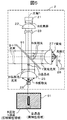
- FIG. 1 is a configuration diagram illustrating an optical system of a projector in Embodiment 1.
- FIG. It is a figure which shows the block diagram of the light source device in Example 1, and the transmission / reflection characteristic of a dichroic mirror.
- 2 is an example of an emission spectrum of a blue laser in Example 1.
- 2 is an example of an emission spectrum of a yellow phosphor in Example 1. It is a principle explanatory drawing of the B light utilization rate improvement by division
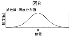
- FIG. 6 is a diagram showing an illuminance distribution of a diffusion plate in Examples 1 to 6.
- 6 is a diagram illustrating a coating method for a B-transmission Y reflection region and a total reflection region of a dichroic mirror in Example 3.
- FIG. It is a block diagram of the light source device in Example 4, and the figure which shows the transmission / reflection characteristic of a dichroic mirror. It is a figure which shows the coating method of the B reflection Y transmissive area
- FIG. 10 is a schematic configuration diagram of a light source portion of a light source device according to a fifth embodiment.
- FIG. 10 is a schematic diagram showing a cross-sectional view of an alumina ceramic plate as a diffusion plate in Example 7.
- FIG. It is a figure explaining the condensing angle (theta) i of the incident light with respect to the diffusion plate in Example 7, and the diffusion angle (theta) o of emitted light. It is a figure explaining the definition of the diffusion angle (theta) o of the emitted light of the diffusion plate in Example 7.
- FIG. It is explanatory drawing which converted each area
- FIG. 10 is a system comparison table of diffusion plates in Example 7.
- FIG. 10 is a configuration diagram of a light source device in Example 8.
- 10 is a configuration diagram of an array lens in Example 8.
- FIG. It is a figure explaining the irradiation area per rotation of the fluorescent substance wheel of the excitation light irradiated to the fluorescent substance wheel in Example 8.
- FIG. It is a figure explaining an example of arrangement
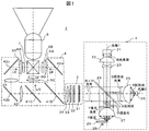
- FIG. 1 is a configuration diagram showing an optical system of a projector in this embodiment.
- an optical system 1 of a projector mainly includes a light source device 2, an illumination optical system 3, a color separation optical system 4, video display elements 6R, 6G, and 6B, and a light combining prism 7 that is a combining optical system.
- a projection lens 8 which is a projection optical system.
- the light source device 2 will be described later.
- blue light B blue band light, hereinafter also referred to as “B light”
- fluorescence Y hereinafter also referred to as yellow light “Y light”.
- a white light W light flux group (note that the white light W is hereinafter also referred to as “W light”) is obtained as B + Y light.
- the fluorescence Y is yellow fluorescence including light in the green band and light in the red band.
- the white light W light beam group is divided into a plurality of lights by a plurality of lens cells of the multi-lens 31 of the illumination optical system 3 and is efficiently guided to the second multi-lens 32 and the polarization conversion element 33. Then, the light is polarized in a predetermined polarization direction by the polarization conversion element 33. The polarized light is collected by the condenser lens 34 and enters the color separation optical system 4.
- the dichroic mirror 41 ⁇ / b> B is irradiated, and among the irradiated white light W, blue light B (blue band light) is reflected, and green light G (green band light, hereinafter “G”) is reflected.
- Light) and red light R (red band light, hereinafter also referred to as “R light”) are transmitted.
- the reflected B light is reflected by the reflecting mirror 42A, passes through the condenser lens 5B, and enters the image display element 6B.
- the G light and the R light transmitted through the dichroic mirror 41B are reflected by the dichroic mirror 41G and the R light is transmitted.
- the reflected G light passes through the condenser lens 5G and enters the image display element 6G.
- the R light transmitted through the dichroic mirror 41G is collected by the relay lens 43 and then reflected by the reflection mirror 42B.
- the reflected R light is collected again by the relay lens 44 and reflected by the reflecting mirror 42C.
- the reflected R light is further collected by the relay lens 5R and incident on the image display element 6R.
- Each video display element forms an image by modulating the light intensity for each pixel in accordance with a video signal (not shown) with respect to incident light, and generates outgoing light by reflection or transmission. Note that the example of FIG. 1 discloses an example of a transmissive image display element.
- the B light, G light, and R light emitted from each image display element are combined as color image light by the light combining prism 7, pass through the projection lens 8, and reach a screen (not shown). That is, an optical image formed by the video display element is enlarged and projected on a screen (not shown).
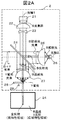
- FIG. 2A shows a conceptual diagram showing the transmission / reflection characteristics of the dichroic mirror 24 extracted at the position corresponding to the optical axis 1.
- the light source 21 is a blue laser (BL), and blue laser light (B light) is emitted around the optical axis 1.
- the lens 22 superimposes the B light beam while condensing it, and the lens 23 turns the B light beam into a parallel light beam.
- the dichroic mirror 24 is irradiated with the B light flux.
- the dichroic mirror 24 has a region of B transmission / Y reflection characteristics as shown in the figure, and a total reflection region is provided at the center of the dichroic mirror. That is, the dichroic mirror 24 has a wide area of the B light transmission Y light reflection characteristic. However, it has a region of total reflection characteristics partially different from the characteristics of the B light transmission Y light reflection.
- an area having a characteristic that occupies a wide area out of the areas provided in the dichroic mirror whose transmission / reflection characteristics are divided into areas is hereinafter referred to as a “wide area characteristic area”. Further, in a partial narrow area, an area different from the characteristic of the “wide area characteristic area” is hereinafter referred to as “different characteristic area”.
- the B transmission / Y reflection characteristic region is a “wide characteristic region”, and the total reflection region is a “different characteristic region”.
- the B light transmission / reflection characteristics in the “wide characteristic area” may be completely uniform, but in order to eliminate color unevenness depending on the incident angle of the left and right light, the cut wavelength of the dichroic coat (for example, 50%) The wavelength may be inclined in the left-right direction. In this case, in the description of each embodiment of the present invention, even if the cut wavelength is inclined, it is considered to belong to the same “wide area characteristic region”. In the description of each embodiment of the present invention, an example in which the “difference characteristic region” has total reflection characteristics or total transmission characteristics is described.
- dichroic coating can be used for some reason within a range that does not affect the present invention. There is also sex. Even in this case, the transmission / reflection characteristics may be completely uniform within the “different characteristic area”, but in order to eliminate color unevenness depending on the incident angle of the left and right light, the cut wavelength of the dichroic coat (for example, 50%) The inclination may be set in the left-right direction. Even in this case, even if the inclination of the cut wavelength is set, it is considered to belong to the same “different characteristic region”.
- the ratio of the total reflection area which is a different characteristic area in the B light area irradiated from the light source 21 to the dichroic mirror is 20% of the irradiation range of the incident light beam.
- about 20% of the irradiated B light beam is reflected and about 80% is transmitted. That is, about 20% of the central portion of the B light beam is reflected out of the B light beam irradiated from the light source 21 to the dichroic mirror 24.
- the B light beam reflected by the dichroic mirror 24 is condensed by the condenser lens 25 and applied to the diffusion plate 26. Then, the B light beam diffused by the diffusion plate 26 around the optical axis 2 that is the optical axis of the condenser lens 25 is transmitted through the condenser lens 25 and irradiated onto the dichroic mirror 24. At this time, the area of the B light beam irradiated on the dichroic mirror 24 is larger than the area of the B light beam irradiated on the dichroic mirror 24 from the light source 21.
- the area expansion ratio of the B light incident area by the diffuser plate is 2 out of the B light beam irradiated from the diffuser plate 26 to the dichroic mirror 24, about 10% is reflected by the shape of the different characteristic area as an example. However, it is possible to transmit about 90%.
- the B light beams that pass through the dichroic mirror 24 are collected by the condenser lens 27 and irradiated onto the phosphor wheel 28.
- the phosphor wheel 28 is coated with a phosphor that emits Y light using B light as excitation light, and is rotated by a motor 29 to prevent burning.
- Y light is emitted from the phosphor wheel 28, passes through the condenser lens 27, and is irradiated onto the dichroic mirror 24.
- the Y light beam is reflected by the dichroic mirror 24 and overlaps with the B light beam to become a W light beam that is a B + Y light beam.
- FIG. 2B shows an example of the emission spectrum of the blue laser according to this example.
- FIG. 2C shows an example of the emission spectrum of the yellow phosphor according to this example.
- the light source device 2 in the present embodiment uses the blue laser as the light source 21, and generates white light W by synthesizing B (blue) + Y (yellow) light. That is, the light source device 2 can be said to be a white light generation unit.
- the dichroic mirror 24 has a B transmission / Y reflection characteristic area as a wide-area characteristic area, and a total reflection area as a different characteristic area at the center of the dichroic mirror. Then, the B light is diffused by the diffusion plate 26 to enlarge the area of the B light. Thereby, it becomes possible to reduce the area ratio of the return light of the B light, which is the light not included in the white light W, to the light source 21, and the B light utilization rate can be increased.
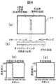
- FIG. 4 an example of a coating method for the B transmission Y reflection region, which is a wide-area characteristic region of the dichroic mirror 24 in this embodiment, and the total reflection region, which is a different characteristic region, and the transmittance characteristics of each region are shown.
- An example will be described.
- 4A is a plan view
- FIG. 4B is a cross-sectional view
- FIG. 4C is a transmittance characteristic of the B transmission Y reflection region
- FIG. 4D is a transmittance characteristic of the total reflection region.
- the dichroic mirror 24 has a dichroic coating having a B-transmission Y-reflection characteristic on one side of a glass substrate, and an AR coating (Anti-Reflective-Coating) on the opposite side. It can be manufactured by applying a mirror coating for the total reflection area.
- the transmittance characteristic of each region is such that the transmittance is at least 95% in the vicinity of 455 nm, which is the wavelength of B light, in the B transmission Y reflection region, which is a wide-area characteristic region.
- the transmittance of light in the green band to the red band in the vicinity of 500 to 700 nm included in the Y light is desirably at least 5%, and desirably close to 0%.
- the total reflection region which is a different characteristic region has a transmittance of at least 5% or less in the entire wavelength region, and is desirably 0%.
- the B light transmission Y light reflection characteristic means that the transmittance is at least 95% around 455 nm which is the wavelength of B light, and the green light around 500 to 700 nm included in Y light. It means that the reflectance of light from the band to the red band is at least 95%.
- the B light reflection Y light transmission characteristic means that the reflectivity is at least 95% around 455 nm, which is the wavelength of B light, and is around 500 to 700 nm included in Y light. It means that the transmittance of light from the green band to the red band is at least 95% or more.
- the total transmission characteristic means that the transmittance in the entire wavelength region from at least the blue band near 455 nm to the red band of 700 nm is at least 95% or more.
- the total reflection characteristic means that the reflectance in all wavelength regions from at least the blue band near 455 nm to the red band 700 nm is at least 95% or more.
- the transmission characteristics and reflection characteristics of the B light and the Y light are configured to be reversed. That is, when there is a B light transmission characteristic in the “wide area characteristic area”, the Y light is configured to have a reflection characteristic. As a result, the characteristic of the “wide area characteristic area” is the B light transmission Y light reflection characteristic. Is set. Further, when there is a B light reflection characteristic in the “wide area characteristic area”, the Y light is configured to have a transmission characteristic. As a result, the characteristic of the “wide area characteristic area” is the B light reflection Y light transmission characteristic. Is set.
- the B light and Y light are configured to have the same transmission characteristics and reflection characteristics. That is, when there is a B light transmission characteristic in the “different characteristic area”, the Y light is also configured to have a transmission characteristic. As a result, the characteristic of the “different characteristic area” is set as the total transmission characteristic. . Further, when there is a B light reflection characteristic in the “different characteristic area”, the Y light is also configured to have a reflection characteristic. As a result, the characteristic of the “different characteristic area” is set as a total reflection characteristic. .
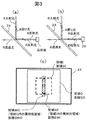
- FIG. 3 (a) does not employ the configuration according to the present embodiment (transmission / reflection characteristic region division and diffusion plate), and (b) illustrates the transmission / reflection characteristic region division and diffusion plate according to this embodiment. It is an example of the optical system of a light source device.
- the area of the incident region I for B incident light is SI
- the area of the incident region O for B diffused light is The total reflection area WI (the reflection characteristic R of B light is R ⁇ 1), which is a different characteristic area of the incident area I of SO and B incident light, is the different characteristic area of the incident area O of the SWI and B diffused light.
- the area of a total reflection region WO (B light reflection characteristic R ⁇ 1) is SWO.
- the B diffused light substantial transmittance T2 can be calculated from (SO-SWO) / SO by the dichroic mirror 24 which is the transmission ratio to the B diffused light.
- SWI / SI can also be expressed as the utilization efficiency of B light incident on the dichroic mirror from the laser light source.
- (SO-SWO) / SO can also be expressed as the utilization efficiency of B light incident on the dichroic mirror from B diffused light.
- SO / SI is set as ⁇ as the area expansion ratio of the incident region of the diffused light
- the meaning of this expression is that the ratio ⁇ of SWO, which is the size of the different characteristic area in the incident area O of the B diffused light to the SWI, which is the size of the different characteristic area in the incident area I of B incident light, is diffused.
- the efficiency of the configuration of FIG. This means that the efficiency of the configuration (a) can be increased.
- the ratio ⁇ of SWO that is the size of the different characteristic area of the incident area O of the B diffused light to the SWI that is the size of the different characteristic area in the incident area I of B incident light is better. become.
- the dichroic mirror 24 is transmitted through B that is a wide-area characteristic region. / Y reflection characteristic region, and a total reflection region which is a different property region is provided in the central portion, and the transmission / reflection characteristics are divided into regions, and the diffuser 26 diffuses the B light, and the B light By expanding the area of B, the B light utilization rate can be increased.
- This example is an example in which, in the projector of Example 1, the coating specifications on the dichroic mirror of the light source device are changed, and the arrangement of the phosphor wheel and the diffusion plate is changed accordingly.
- FIG. 5 is a diagram showing the configuration of the light source device of the projector and the transmission / reflection characteristics of the dichroic mirror in this embodiment. 5, components having the same functions as those in FIG. 2A are given the same reference numerals, and descriptions thereof are omitted. 5 is different from FIG. 2A in that the transmission / reflection characteristics of the dichroic mirror are different and the positions of the phosphor wheel and the diffusion plate are interchanged.
- the dichroic mirror 91 is irradiated with the B light beam made substantially parallel by the lens 23.
- the dichroic mirror 91 has a B reflection / Y transmission characteristic region which is a wide characteristic region, and a total transmission region which is a different characteristic region is provided at the center of the dichroic mirror.
- the dichroic mirror 91 has a wide area of the B light reflection Y light transmission characteristic, which is a wide area characteristic area, but is an area having a total transmission characteristic that is partially different from the B light reflection Y light transmission characteristic (different characteristic area). ).
- the ratio of the total transmission region is 20% of the entire B light region irradiated from the light source 21 to the dichroic mirror.
- the B light flux irradiated to the dichroic mirror 91 is 80%.
- the degree is reflected and about 20% is transmitted. That is, about 20% of the central portion of the B light beam is transmitted through the B light beam irradiated from the light source 21 to the dichroic mirror 91.
- the second embodiment differs from the first embodiment in the transmission / reflection characteristics of the dichroic mirror, but the wide characteristic area having the predetermined transmission / reflection characteristic area and the different characteristic area partially different from the predetermined transmission / reflection characteristics are the same.
- the concept is common in that it has a dichroic mirror.
- the B light beam reflected by the dichroic mirror 91 is condensed by the condenser lens 27 and irradiated onto the phosphor wheel 28.
- Y light is emitted from the phosphor wheel 28, passes through the condenser lens 27, is irradiated onto the dichroic mirror 91, and the Y light beam passes through the dichroic mirror 91.
- the B light beam transmitted through the dichroic mirror 91 is condensed by the condenser lens 25 and irradiated to the diffusion plate 26.
- the B light beam diffused by the diffusion plate 26 with the optical axis 1 as the center passes through the condenser lens 25 and is irradiated onto the dichroic mirror 91.
- the area of the B light beam irradiated on the dichroic mirror 91 is larger than the area of the B light beam irradiated on the dichroic mirror 91 from the light source 21.
- the area expansion ratio of the B light incident region by the diffuser plate is 2 out of the B light beam irradiated from the diffuser plate 26 to the dichroic mirror 91, as an example, about 10% is transmitted due to the shape of the different characteristic region. However, it is possible to reflect about 90%.
- the B light beam reflected by the dichroic mirror 91 overlaps with the Y light beam to become a B + Y light beam. As a result, even with the configuration of the second embodiment, the B light utilization rate can be increased to the same extent as in the first embodiment.
- FIG. 6 is a diagram showing a coating method for the B reflection Y transmission region and the total transmission region of the dichroic mirror 91 in this embodiment, and the transmittance characteristics of each region.
- 6A is a plan view
- FIG. 6B is a cross-sectional view
- FIG. 6C is a transmittance characteristic of the B reflection Y transmission region
- FIG. 6D is a transmittance characteristic of the total transmission region.
- the dichroic mirror 91 can be manufactured by applying an AR coating on one side of a glass substrate, and applying a dichroic coating having a B reflection Y transmission characteristic on the opposite side and an AR coating for the entire transmission region. .
- FIG. 6 is a diagram showing a coating method for the B reflection Y transmission region and the total transmission region of the dichroic mirror 91 in this embodiment, and the transmittance characteristics of each region.
- 6A is a plan view
- FIG. 6B is a cross-sectional view
- FIG. 6C is a transmittance characteristic
- the transmittance characteristics of each region are such that the transmittance is at least 5% or less in the vicinity of 455 nm, which is the wavelength of B light, in the B reflection Y transmission region which is a wide-area characteristic region.
- the transmittance of light in the green band to the red band in the vicinity of 500 to 700 nm included in Y light is desirably at least 95% and desirably as close as possible to 100%.
- the total transmission region which is a different characteristic region has a transmittance of at least 95% or more in all wavelength regions, and is desirably 100% as much as possible.
- the B incident light substantial transmittance T3 can be calculated from SWI / SI by the dichroic mirror 91 which is the ratio of the transmitted light to the B incident light from the laser light source.
- the B diffused light substantial reflectance R3 can be calculated from (SO-SWO) / SO by the dichroic mirror 91 which is the transmission ratio to the B diffused light.
- the B light utilization rate E3 of the light source device is the utilization efficiency (SWI) of the B light incident on the dichroic mirror from the laser light source. / SI) and the utilization efficiency ((SO-SWO) / SO) of the B light incident on the dichroic mirror from the B diffused light.
- the B light utilization rate E3 of the light source device of the present embodiment is also different from the area expansion ratio ⁇ of the diffused light incident region and the B incident light incident region I in the same manner as in the equation modification of the first embodiment.
- the dichroic mirror 91 is configured to have B reflection / It has a Y transmissive characteristic area and a total transmissive area that is a different characteristic area at the center, and the transmission / reflection characteristics are divided into areas.
- the diffuser plate 26 diffuses the B light, By expanding the area, the B light utilization rate can be increased.
- the present embodiment even if the configuration is different from that of the first embodiment, it is possible to generate a white light from the laser light source more suitably and to realize a projector used for image display as much as the first embodiment. It becomes possible.
- the present embodiment describes an example in which the different characteristic region of the dichroic mirror in the light source device in the projector according to the first embodiment is arranged at a position offset from the central portion where the optical axis 2 that is the optical axis of the condenser lens 25 and the dichroic mirror are in contact. To do.
- FIG. 7 is a diagram showing the configuration of the light source device and the transmission / reflection characteristics of the dichroic mirror in this example. 7, components having the same functions as those in FIG. 2A are given the same reference numerals, and descriptions thereof are omitted.
- the position of the different characteristic region in the dichroic mirror is arranged near the central portion where the optical axis 2 and the dichroic mirror are in contact with each other, whereas in FIG. The position is offset from the center where the shaft 2 and the dichroic mirror are in contact.
- the different characteristic area is simply changed within the range where the B light incident light from the B color laser light source 21 enters.
- the characteristic region may be disposed only at a position offset from the central portion where the optical axis 2 and the dichroic mirror are in contact.
- a different characteristic region can be further formed. Can be offset from 2.
- FIG. 7 shows an example in which both the offset of the optical axis 1 of the laser light source 21 and the offset from the center of the different characteristic region are employed as an example.
- the dichroic mirror 92 is irradiated with the B light beam collimated by the lens 23.
- the dichroic mirror 92 has a B transmission / Y reflection characteristic region that is a wide-area characteristic region, and the total reflection region that is a different characteristic region is offset from a position in contact with the optical axis 2.
- Prepared for position For example, if the ratio of the total reflection area is 20% of the B light area irradiated from the light source 21 to the dichroic mirror, about 20% of the B light beam irradiated to the dichroic mirror 92 is reflected and 80%. The degree is transparent. That is, 20% of the portion of the B light beam irradiated from the light source 21 to the dichroic mirror 92 that is offset from the center of the B light beam is reflected.
- the B light beam reflected by the dichroic mirror 92 is diffused by the diffusion plate 26 and is irradiated onto the dichroic mirror 92. At this time, the area of the B light beam irradiated on the dichroic mirror 92 is larger than the area of the B light beam irradiated on the dichroic mirror 92 from the light source 21.
- the ratio of being reflected in the different characteristic area and the ratio of being transmitted in the wide characteristic area is calculated based only on the area ratio.
- the area ratio calculation when the area expansion ratio of the B light incident region by the diffuser is 2, as an example, a configuration in which about 10% is reflected and about 90% is transmitted by the shape of the different characteristic region is considered.
- the position of the different characteristic region is offset from the central portion where the optical axis 2 contacts the dichroic mirror.
- FIG. 8 shows an illuminance distribution diagram of light emitted from the diffusion plate 26. As shown in FIG.
- the B light beam passing through the dichroic mirror 92 is irradiated to the phosphor wheel 28.
- Y light is emitted from the phosphor wheel 28 around the optical axis 3 that is the optical axis of the condenser lens 27 and is irradiated on the dichroic mirror 92.
- the Y light beam is reflected by the wide-area characteristic region of the dichroic mirror 92 and overlaps with the B light beam to become a B + Y light beam.
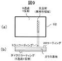
- FIG. 9 is a diagram showing a coating method for the B transmission Y reflection area, which is a wide-area characteristic area, and the total reflection area, which is a different characteristic area, of the dichroic mirror 92 in this embodiment.
- FIG. 9A is a plan view
- FIG. 9B is a cross-sectional view.
- the dichroic mirror 92 has a dichroic coating with B transmission Y reflection characteristics on one side of a glass substrate, an AR coating on the opposite side, and a mirror coating for a total reflection region on the opposite side. It can be manufactured by applying.
- the dichroic mirror 92 is made to transmit B / Y, which is a wide characteristic region.
- the B light utilization rate can be increased as compared with the first embodiment, and it is possible to generate white light from a laser light source more suitably and realize a projector used for image display. It becomes possible.
- the different characteristic region of the dichroic mirror in the light source device is arranged at a position offset from the central portion where the optical axis 3 that is the optical axis of the condenser lens 25 and the dichroic mirror are in contact. explain.
- FIG. 10 is a diagram showing the configuration of the light source device and the transmission / reflection characteristics of the dichroic mirror in this example. 10, components having the same functions as those in FIG. 5 are given the same reference numerals, and descriptions thereof are omitted.
- the position of the different characteristic region in the dichroic mirror is arranged near the central portion where the optical axis 3 and the dichroic mirror are in contact with each other, whereas in FIG. The position is offset from the center where the shaft 3 and the dichroic mirror are in contact.
- the different characteristic area is simply changed within the range where the B light incident light from the B color laser light source 21 is incident.
- the characteristic region may be disposed only at a position offset from the central portion where the optical axis 3 and the dichroic mirror are in contact. Further, by disposing the optical axis 1 of the B color laser light source 21 offset from the optical axis 3, the different characteristic region can be further offset from the optical axis 3.
- FIG. 10 shows an example in which both the offset of the optical axis 1 of the laser light source 21 and the offset from the center of the different characteristic region are employed as an example.
- the dichroic mirror 93 is irradiated with the B light beam made parallel by the lens 23.
- the dichroic mirror 93 has a region of B reflection / Y transmission characteristics as a wide area characteristic area, and a position where the entire transmission area is offset from a position in contact with the optical axis 3 as a different characteristic area.
- the ratio of the total transmission region, which is a different characteristic region is 20% of the B light region irradiated from the light source 21 to the dichroic mirror
- about 80% of the B light beam irradiated to the dichroic mirror 93 is about 80%. Reflected and about 20% transmitted. That is, about 20% of the portion of the B light beam irradiated from the light source 21 to the dichroic mirror 93 is offset from the center of the B light beam.
- the B light beam reflected by the dichroic mirror 93 is applied to the phosphor wheel 28.
- Y light is emitted from the phosphor wheel 28, is applied to the dichroic mirror 93, and the Y light beam is transmitted through the dichroic mirror 93.
- the B light beam transmitted through the dichroic mirror 93 is irradiated to the diffusion plate 26 and diffused around the optical axis 3 that is the optical axis of the condenser lens 25.
- the B light beam diffused by the plate 26 is applied to the dichroic mirror 93.
- the area of the B light beam irradiated on the dichroic mirror 93 is larger than the area of the B light beam irradiated on the dichroic mirror 93 from the light source 21.
- the ratio of being transmitted in the different characteristic area and the ratio of being reflected in the wide area characteristic area is calculated based only on the area ratio.
- the area expansion ratio of the B light incident area by the diffuser is 2, as an example, a configuration in which 10% is transmitted and about 90% is reflected by the shape of the different characteristic area is considered.
- the position of the different characteristic region is offset from the central portion where the optical axis 3 and the dichroic mirror are in contact.
- the illuminance decreases as the illuminance distribution of the light emitted from the diffusion plate 26 deviates from the center position.
- the position of the different characteristic area is offset from the center part where the optical axis 3 and the dichroic mirror are in contact as in the third embodiment, so that even if the area of the different characteristic area is the same as in the second embodiment, Of the B diffused light from the diffuser plate 26, the B diffused light that is transmitted through the dichroic mirror 93 and returns to the light source 21 is not the peak intensity at the center angle in FIG. Compared to FIG. 5 of the second embodiment, the return light to the laser light source can be reduced. For example, if the relative ratio effect of the diffused light intensity in FIG. 8 due to this offset is 50%, the area expansion ratio of the B light incident area by the diffuser is 2, and only about 10% due to the shape of the different characteristic area only by area ratio calculation. In the configuration in which about 90% is transmitted and reflected, about 5% of the B light beam irradiated from the diffusion plate 26 onto the dichroic mirror 93 is transmitted and about 95% is reflected in consideration of the actual intensity distribution of FIG. It will be.
- the B light beam reflected by the wide characteristic region of the dichroic mirror 93 overlaps with the Y light beam to become a B + Y light beam.
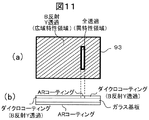
- FIG. 11 is a diagram showing a coating method for the B reflection Y transmission region, which is a wide-area characteristic region, and the total transmission region, which is a different characteristic region, of the dichroic mirror 93 in this embodiment.
- FIG. 11A is a plan view and FIG. 11B is a cross-sectional view.
- the dichroic mirror 93 can be manufactured by applying an AR coating on one side of a glass substrate, and applying a dichroic coating having a B reflection Y transmission characteristic on the opposite side and an AR coating for the entire transmission region. .
- the dichroic mirror 93 is made to have B reflection / Y which is a wide-area characteristic region.
- the present embodiment it is possible to increase the B light utilization rate as compared with the second embodiment, and it is possible to generate white light from a laser light source more suitably and realize a projector used for image display. It becomes possible.
- the dichroic mirror transmission / reflection area is divided, and a plurality of lasers are used as light sources.
- a plurality of lasers are used as light sources.
- FIG. 12 is a schematic configuration diagram of a light source portion of the light source device in the present embodiment.
- FIG. 12 shows details of the configuration of the light source 21 in the configuration of the light source device of FIG. 2A, FIG. 5, FIG. 7, or FIG. Specifically, two light sources 21-1 and 21-2 are used as the light source 21 and are driven by the power source 1 (20-1) and the power source 2 (20-2), respectively. It has the control part 10 which controls.
- FIG. 13 is a diagram showing a divided configuration of the transmission / reflection area of the dichroic mirror corresponding to Example 1 (configuration of FIG. 2A) and its modification.
- FIG. 13A shows a configuration corresponding to the first embodiment.
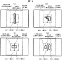
- an irradiation region E21 ⁇ in which the B light from the light source 21-1 is irradiated to a region that spans the B transmission Y reflection region (wide characteristic region M) and the total reflection region (different characteristic region W), respectively.
- an irradiation region E21-2 irradiated with the B light from the light source 21-2.
- FIG. 13A a region obtained by combining the irradiation region E21-1 irradiated with the B light from the light source 21-1 and the irradiation region E21-2 irradiated with the B light from the light source 21-2 is shown in FIG. Corresponds to region I. Note that the B diffused light incident region shown in FIG. 13A corresponds to the region O in FIG.
- the areas are arranged symmetrically, the ratio of the wide area characteristic area M and the different characteristic area W in the irradiation area E21-1, and the wide area characteristics in the irradiation area E21-2.
- the ratio of the region M and the different characteristic region W is the same. Therefore, if the laser intensity of the light sources 21-1 and 21-2 is changed, the intensity of the light output from the light source device 2 is adjusted without changing the ratio of the B light and the Y light output from the light source device 2.
- a dimming function can be realized.
- FIG. 13B is a modification of the area division of FIG. 13A, and unlike FIG. 13A, the total reflection area, which is the different characteristic area W, is wide in the width direction of the paper surface, and the light source 21- 1 is an area (corresponding to the area I in FIG. 3C) that is a combination of the irradiation area E21-1 irradiated with the B light from 1 and the irradiation area E21-2 irradiated with the B light from the light source 21-2. Is included.
- the different characteristic region W since the different characteristic region W is included in the region I, the different characteristic region W corresponds to both the region WI and the region WO in the example of FIG.
- the size of the different characteristic region in the incident region O of the B diffused light with respect to SWI which is the size of the different characteristic region in the incident region I of B incident light.
- the B light utilization efficiency is always greater than the configuration of
- the B light is used more than the configuration in which the different characteristic region W is not included in the region I as shown in FIG.
- the rate can be increased.
- the different characteristic area W is elongated at the vertical boundary line between the irradiation area E21-1 and the irradiation area E21-2.
- the positions of the E21-1, the irradiation area E21-2, and the relative position in the left-right direction of the different characteristic area W of the dichroic mirror are greatly shifted, the wide characteristic area M and the different characteristic area W in the irradiation area E21-1 And the ratio of the wide characteristic area M and the different characteristic area W in the irradiation area E21-2 greatly change.
- the power source that controls the one laser light source fails. Since only the light that has passed through the wide area characteristic region M is used from the light incident on the dichroic mirror from the light source, either the B light or the Y light from the light source device 2 (example in FIG. 13A) In this case, only Y light) is output, and white light cannot be generated.
- the configuration of FIG. 13A in the configuration of FIG. 13A
- FIG. 13C is a modified example of further different area division.
- the total reflection area which is the different characteristic area W is configured to be asymmetric on the left and right.
- the ratio of the wide area characteristic region M and the different characteristic area W in the irradiation area E21-1 is different from the ratio of the wide area characteristic area M and the different characteristic area W in the irradiation area E21-2.
- the ratio of the B light and the Y light that the B light from the light source 21-1 finally contributes to the output light of the light source device 2 and the B light from the light source 21-2 are finally output from the light source device 2.
- the ratio of B light and Y light contributing to light can be varied. Then, the light intensity of the light source 21-1 is variably controlled by the control of the power source 1, or the light intensity of the light source 21-2 is variably controlled by the control of the power source 2. By changing the relative ratio of the light source 21-2 to the light intensity, it is possible to control both the color and intensity of the light output from the light source device 2. That is, the toning function and the dimming function of the light output from the light source device 2 can be realized.
- the different characteristic region W is included in the region (region I) that includes the irradiation region E21-1 and the irradiation region E21-2.
- the light utilization rate is high.
- FIG. 13D is a modified example of further different area division.
- the ratio of the region M and the different characteristic region W is made different. Therefore, similarly to the example of FIG. 13C, the light intensity of the light source 21-1 is variably controlled by the control of the power supply 1, or the light intensity of the light source 21-2 is variably controlled by the control of the power supply 2.
- the relative ratio between the light intensity of the light source 21-1 and the light intensity of the light source 21-2 it is possible to control both the color and intensity of the light output from the light source device 2.
- the different characteristic region W (total reflection region) has an independent shape for each irradiation region from the left and right light sources. Further, different characteristic areas W are provided at positions separated from the boundary lines of the irradiation areas from the left and right light sources. Thereby, depending on the assembling accuracy of the optical component, the position of the irradiation area E21-1, the position of the irradiation area E21-2, and the relative position of the different characteristic area W of the dichroic mirror are shifted in the vertical direction even if they are shifted in the horizontal direction.
- the different characteristic region W is included in the region (region I) that combines the irradiation region E21-1 and the irradiation region E21-2, so that the B light utilization rate is high.
- FIG. 14 is a diagram showing a divided configuration of the transmission / reflection area of the dichroic mirror corresponding to the second embodiment and its modification.
- FIG. 14A shows a configuration corresponding to the second embodiment.
- FIG. 14A illustrates an example in which the configuration shown in FIG. 12 is adopted as the light source 21 in the configuration of FIG. 5 of the second embodiment, and FIGS. 14B, 14C, and 14D are illustrated. This is a modified example.
- FIGS. 14A, 14B, 14C, and 14D the divided configuration example of the transmission / reflection area of the dichroic mirror described in FIGS. 14A, 14B, 14C, and 14D is shown in FIGS.
- the characteristic of the different characteristic region W is changed to total transmission. If the description of FIG. 13 is read in accordance with the change of the characteristic, the configuration and the effect thereof will also be the description of each figure of FIG. Therefore, the description of each figure in FIG. 14 is assumed to be described by the replacement of each figure in FIG.
- the B light utilization rate depends on the relationship between the shape of the different characteristic area W and the irradiation areas of a plurality of light sources on the dichroic mirror. Improvement, realization of the dimming function, realization of the toning function, reduction of the effect of relative displacement due to assembly accuracy of the optical component, or the like, or a combination of these.
- the irradiation region E21-1 and the irradiation region E21-2 do not overlap each other has been described.
- the irradiation region E21-1 and the irradiation region E21-2 may partially overlap, and this case is also an aspect of a modification of the present embodiment.
- the ratio between the wide characteristic area M and the different characteristic area W in each irradiation area satisfies the above description, the same effect as the above description can be obtained.
- FIG. 15 shows the light source portion of the light source device in the present embodiment. It is a schematic block diagram. 15, three light sources 21-1, 21-2, and 21-3 are used in the configuration of the light source device of FIG. 2A, FIG. 5, FIG. 7, or FIG.
- the control unit 11 is driven by the power source 2 (20-2) and the power source 3 (20-3), and controls the power source 1, the power source 2, and the power source 3, respectively.
- FIG. 16 is a diagram showing a divided configuration of the transmission / reflection area of the dichroic mirror corresponding to Example 1 (configuration of FIG. 2A) and its modification.
- FIG. 16A shows a configuration corresponding to the first embodiment.
- the left B transmission Y reflection region (wide characteristic region M) has an irradiation region E21-1 irradiated with B light from the light source 21-1, and the left B transmission Y reflection region.
- Irradiation region E21- where B light from the light source 21-2 is irradiated to a region extending over (wide area characteristic region M), total reflection area (different characteristic area W), and right B transmission Y reflection area (wide area characteristic area M) 2 and an irradiation region E21-3 on which the B light from the light source 21-3 is irradiated on the right B transmission Y reflection region (wide-area characteristic region M).
- the ratio of the wide area characteristic area M and the different characteristic area W in the irradiation area E21-2, and the ratio of the wide area characteristic area M and the different characteristic area W in the irradiation area E21-1 and the irradiation area E21-3 (in this figure, different characteristics) Since the area W is 0%), the ratio of the B light and the Y light output from the light source device 2 is changed by changing the laser intensity of the light sources 21-1, 21-2, and 21-3. Functions and dimming functions can be realized.
- FIG. 16B is a modification of the area division of FIG. 16A.
- the total reflection area which is the different characteristic area W is wide in the width direction of the paper surface, and the light source 21-1 Irradiation region E21-1 irradiated with B light from the light source, irradiation region E21-2 irradiated with B light from the light source 21-2, and irradiation region E21-3 irradiated with B light from the light source 21-3 are included in the region (corresponding to the region I in FIG. 3C).
- the total reflection area which is the different characteristic area W, covers all of the irradiation area E21-1, the irradiation area E21-2, and the irradiation area E21-3.
- FIG. 16C is a modified example of area division.
- there are two irradiation areas of a plurality of laser light sources whereas in the configuration of FIG. 16C, the irradiation area E21-1, the irradiation area E21-2, and the irradiation area E21-3. It has increased to three. Further, the ratio of the wide characteristic area M and the different characteristic area W in the three irradiation areas is changed.
- both the color and intensity of light output from the light source device 2 can be controlled. Further, since the number of area divisions is larger than that in FIG. 13C, the resolution of color and intensity control can be improved.
- FIG. 16D is a modified example of area division.
- the ratio of the wide area characteristic region M and the different characteristic area W in the irradiation area E21-1, and the wide area characteristic in the irradiation area E21-2 is different from the ratio between the wide area characteristic area M and the different characteristic area W in the irradiation area E21-3. Therefore, similarly to the example of FIG. 16C, the light intensity of the light output from the light source device 2 is controlled by variably controlling the light intensity of the light source 21-1, the light intensity of the light source 21-2, and the light intensity of the light source 21-3. Both the color and the intensity can be controlled. Further, since the number of area divisions is larger than that in FIG. 13D, the resolution of the color and intensity control can be improved.
- the different characteristic region W (total reflection region) has an independent shape for each irradiation region from the three light sources. Further, different characteristic regions W are provided at positions separated from the boundary lines of the respective irradiation regions.
- the position of the irradiation region E21-1, the position of the irradiation region E21-2, the position of the irradiation region E21-3, and the relative position of the different characteristic region W of the dichroic mirror are Regardless of whether it is shifted in the horizontal direction or the vertical direction, the ratio of the wide area characteristic area M and the different characteristic area W in the irradiation area E21-1, and the wide area characteristic area M and the different characteristic area in the irradiation area E21-2.
- the ratio of W and the ratio of the wide area characteristic area M and the different characteristic area W in the irradiation area E21-3 can be hardly changed.
- the position of the irradiation region E21-1 and the irradiation region depending on the toning function and the light control function of the light output from the light source device 2, the assembly accuracy of the optical components, and the like It is possible to realize both the position of E21-2, the position of the irradiation area E21-3, and the influence of the relative position shift of the different characteristic area W of the dichroic mirror, which is a desirable mode.
- the different characteristic region W is included in the region (region I) including the irradiation region E21-1, the irradiation region E21-2, and the irradiation region E21-3.
- the light utilization rate is high.
- FIG. 17 is a diagram showing a divided configuration of the transmission / reflection area of the dichroic mirror corresponding to the second embodiment and its modification.
- FIG. 17A shows a configuration corresponding to the second embodiment.
- FIG. 17A illustrates an example in which the configuration shown in FIG. 15 is adopted as the light source 21 in the configuration of FIG. 5 of the second embodiment, and FIGS. 17B, 17C, and 17D are illustrated. This is a modified example.
- FIGS. 16 (b), FIG. 16 (c), and FIG. 16 (d) divide configuration examples of the transmission / reflection area of the dichroic mirror.
- the characteristic of the different characteristic region W is changed to total transmission.
- the B light utilization rate depends on the relationship between the shape of the different characteristic area W and the irradiation areas of a plurality of light sources on the dichroic mirror. Improvement, realization of the dimming function, realization of the toning function, reduction of the effect of relative displacement due to assembly accuracy of the optical component, or the like, or a combination of these. Moreover, the resolution can be further improved in the light control function and the color control function.
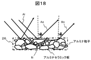
- FIG. 18 is a schematic diagram showing a cross-sectional view of an alumina ceramic plate as the diffusion plate 26 in the present embodiment.
- the alumina ceramic plate is an aggregate of alumina particles having a random shape, and has a property of allowing incident light to be transmitted and reflected at random without performing uneven processing on the reflecting surface. Therefore, for example, even in the case of the outgoing lights Ao and Bo that are emitted at the same angle as shown in the figure, Ai and Bi that are not only light that has passed through the same path but also light that has passed through different paths are included. That is, even if the emitted light is emitted at the same angle, it includes light with different optical path lengths, which is effective in reducing speckle noise.
- FIG. 19 is a diagram for explaining the condensing angle ⁇ i of incident light and the diffusion angle ⁇ o of outgoing light with respect to the diffusion plate in the present embodiment.
- the incident light on the diffusion plate 26 is condensed by the condenser lens 25 and is incident on the diffusion plate 26 at a condensing angle ⁇ i.
- the light emitted from the diffusion plate 26 is emitted at a diffusion angle ⁇ o.
- the definition of the diffusion angle ⁇ o in this embodiment will be described with reference to FIG. FIG.
- the intensity distribution of light emitted from the diffusion plate 26 shows the intensity distribution of light emitted from the diffusion plate 26, where the vertical axis indicates the intensity and the horizontal axis indicates the angle of the diffused light with respect to the normal line of the diffusion plate. As shown in FIG. 20, the intensity decreases as the distance from the center shifts. When the peak intensity of the emitted light is 100%, the angle at which the intensity of the emitted light is 50% is determined in this embodiment. It is defined as the diffusion angle ⁇ o.
- FIG. 21 illustrates an explanatory diagram when the region I, the region O, the region WI, and the region WO of the dichroic mirror 24 illustrated in FIG. 3C are converted into a circular region model.
- the shape of the different characteristic region W is as shown in FIGS. 13B, 13C, 14D, 14B, 14C, 16D, 16B, 16C, and 16D. ), Any shape shown in FIGS. 17B, 17C, and 17D can be converted into the circular model shown in FIG.
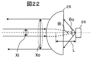
- FIG. 22 shows an optical path in the vicinity of the diffusion plate in the present embodiment.
- Xi is the diameter of the circular region of incident light
- Xo is the diameter of the circular region of outgoing light
- L is a focal length.
- this equation can be modified as (SO-SWO) / SO> (SI-SWI) / SI, and this equation can be further modified as 1-SWO / SO> 1-SWI / SI.
- SO / SWI refers to the area of SWI that is the size of the different characteristic region WI in the B light incident region I in the dichroic mirror (that is, the cross-sectional area of the B light beam toward the condenser lens 25). This is a ratio of the area SO of the region O of the B diffused light returning to the dichroic mirror (that is, the cross-sectional area of the B light flux returning from the condenser lens 25). This shows the effect of increasing the area.
- SI / SWI is the reciprocal of the substantial reflectance R2 in the configuration of FIG. SWO / SWI is ⁇ already described. Therefore, SO / SWI> (SI / SWI) ⁇ (SWO / SWI) can be transformed into SO / SWI> ⁇ / R2.
- Is included in the incident region I, ⁇ 1, so that SO / SWI> 1 / 0.2, that is, SO / SWI> 5. That is, the area ratio of SO / SWI needs to exceed 5 times in order to exceed the B light utilization rate in the conventional system by the function of the diffusion plate 26.
- the focal length L in FIG. 22 is preferably about 15 mm, and the area in FIG. SWI is preferably about 35 square mm.
- the allowable range of the focal length L in FIG. 22 is about 12 mm to 30 mm
- the allowable range of the area SWI in FIG. 21 is about 25 square mm to 42 square mm.
- the allowable range of Xi is 5.64 mm to 7.31 mm.
- the characteristics of the diffusion angle of the diffusion plate 26 can be easily adjusted by the projector model as the aperture size of the panel used for the video display elements 6R, 6G, and 6B and the design parameters of each optical element of the optical system of the light source device 2 are increased. Therefore, in order to reduce the cost of the diffusion plate 26, it is desirable to use a diffusion plate of a common system for a plurality of projector models having different panel opening sizes. Then, the allowable range of the focal length L in FIG. 22 is about 12 mm to 30 mm, and the allowable range of the area SWI in FIG. 21 is about 25 square mm to 42 square mm (in the allowable range of Xi, 5.64 mm to 7 mm). It is necessary to obtain a condition for the diffusion angle in which the area ratio of SO / SWI exceeds 5 times in all ranges of both of .31 mm).
- the conditional expression ⁇ o> 2 ⁇ arcsin (( ⁇ 5 ⁇ Xi / 2) / L) may be obtained as a diffusion angle ⁇ o.
- the largest required angle of the diffusion angle ⁇ o in the allowable range of L and Xi is 12 mm, which is the minimum value of the allowable range, and Xi is the maximum value of the allowable range.
- a diffusion plate that can exceed the B light utilization rate in the conventional method and the condition of a lower cost diffusion plate is that the diffusion angle ⁇ o> 86 °.
- a satisfying diffusion plate may be used.
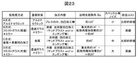
- FIG. 23 is a table comparing the case of using an alumina ceramic plate and the case of another method as an example of the diffusion plate used in the projector of this embodiment.
- four methods are compared as the diffusion plate method.
- the A method is a method in which the alumina ceramic plate described above is used as a reflective diffusion plate.
- the B system is a system in which a diffusing plate is formed by adding a frosted glass with sandblasting or etching to both surfaces of the glass and a mirror on the back thereof.
- the C method is a method in which an uneven surface processing is performed on a metal and used as a reflective diffusion plate.
- the D system is a system in which a reflective diffuser plate is formed by adding a frosted glass having a rough surface processed by sandblasting or etching on one side of the glass and a back surface thereof.
- the D method is a method of adding a mirror to the back surface of the frosted glass by sandblasting or etching on one side of the glass, and forming a reflective diffuser plate (in contrast to the B type, the frosted glass is one side of the glass). It can be said that the method has been changed to only).
- FIG. 23 shows the results of comparing the substrate material, processing details, outgoing light diffusion angle ⁇ o, speckle amount of noise, and cost for each method.
- the A method uses only an alumina ceramic plate, and the C method uses only metal.
- the B method and the D method require a transmission glass and a mirror. Therefore, in consideration of the cost of the substrate material portion, the B method and D method that require a plurality of substrate materials are relatively disadvantageous.
- the A method can be manufactured by simply pressing alumina ceramic, and uneven processing is not required. This is advantageous in terms of processing cost.
- the other B method, C method, and D method are disadvantageous in terms of processing cost because the reflecting surface needs to be processed with unevenness.
- the A-type alumina ceramic method generates random diffused outgoing light regardless of the condensing angle of incident light, and the outgoing light diffusion angle ⁇ o is as large as about 120 °.
- random diffused outgoing light is generated regardless of the collection angle of incident light, and the outgoing light diffusion angle ⁇ o is about 40 °.
- the outgoing light diffusion angle depends on the condensing angle of the incident light, and the outgoing light diffusion angle is obtained by adding the diffusion angle increasing effect of the diffusion plate to the condensing angle of the incident light.
- the collection angle of incident light is about 14 °
- the D-type diffusion angle increase effect is about 6 °
- the A method and the B method are small, while the C method and the D method are medium or large.
- the A-type alumina ceramic method is relatively excellent.
- the B method and D method that require a plurality of substrate materials must be expensive, but the A method and C method are relatively inexpensive. . From the viewpoint of overall cost, the A type alumina ceramic method is relatively excellent.
- any of the comparison items is advantageous, and in particular, the emission diffusion angle ⁇ o sufficiently satisfies the above-described conditional expression of the diffusion angle, and noise such as speckle is also present. It can be seen that it is advantageous to use a relatively inexpensive and inexpensive alumina ceramic diffusion plate.
- the projector according to the present embodiment described above can provide an inexpensive projector with a higher B light utilization rate by using a diffuser plate with an emitted light diffusion angle satisfying ⁇ o> 86 °.
- a diffusion plate using alumina ceramic a more suitable projector can be realized.
- the conversion efficiency of phosphors decreases as the amount of excitation light increases. This is called luminance saturation. For this reason, in this embodiment, the area of the excitation light applied to the phosphor is increased, and the density of the excitation light is reduced, thereby suppressing a decrease in phosphor conversion efficiency due to luminance saturation.
- the optical system of the projector according to the present embodiment is obtained by changing the light source device 2 to the configuration shown in FIG. 24 in the optical system shown in FIG. Since the configuration and operation of other parts are the same as those in the first embodiment, the description thereof is omitted.
- FIG. 24 is a configuration diagram of the light source device in the present embodiment. 24, components having the same functions as those in FIG. 2 are given the same reference numerals, and descriptions thereof are omitted. 24 differs from FIG. 2 in that array lenses 101 and 102 are arranged in front of the dichroic mirror 24. FIG. Thereby, the excitation light of the specific shape to the phosphor wheel is formed. Details of the array lens will be described later. In FIG.
- the blue laser light emitted from the light source 21 is converted into a parallel light beam by the lenses 22 and 23, divided for each lens cell of the array lenses 101 and 102, and after passing through the dichroic mirror 24, While being condensed by the lens 27, it is superimposed on a lens cell basis and is irradiated on the phosphor wheel 28 in a similar shape of the lens cell. That is, the array lenses 101 and 102 function as a generating lens that generates rectangular excitation light.
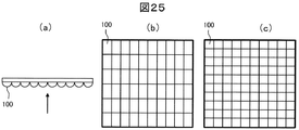
- FIG. 25 is a configuration diagram of an array lens in the present embodiment.
- (a) is a side view
- (b) and (c) are front views as viewed from the arrow direction in (a).
- the array lens has a plurality of lens cells 100 each having a rectangular shape as viewed from the direction in which the optical axis 1 extends, and is arranged in a matrix (two-dimensional).
- An example in which the aspect ratio of the rectangular shape of the lens cell is not 1: 1
- (c) shows a case in which the aspect ratio is 1: 1.
- the lens cell division of the first array lens 101 and the lens cell division of the second array lens 102 are both the same lens cell division shown in FIG. 25, and each of the lens cells of the array lenses 101 and 102 has a one-to-one relationship. It corresponds with.
- the light incident on the array lens 101 is spatially divided and emitted from each lens cell, and the light emitted from each lens cell forms an image on the lens cell of the corresponding array lens 102.
- Light emitted from each of the plurality of lens cells of the array lens 102 is collected by the condenser lens 27 via the dichroic mirror 24 and forms an image on the phosphor wheel 28.
- the curvature of each lens cell is appropriately determined in each cell of each array lens so as to satisfy a conjugate relationship described later.
- the position of the array lens 101 and the curvature of each lens cell Is configured so that the light source 21 and each lens cell of the array lens 102 are optically substantially conjugate. Further, light having a shape similar to the shape of the lens cell of the array lens 101 corresponding to each lens cell of the array lens 102 is projected onto the phosphor wheel 28. That is, the position of the array lens 102 and the curvature of each lens cell are set so that each lens cell of the corresponding array lens 101 and the phosphor wheel surface have an optically conjugate relationship.
- the light incident on the array lens 101 is superimposed on a lens cell basis and is irradiated on the phosphor wheel 28 in a shape similar to the rectangular lens cell of the array lens 101.
- the optical system using the plurality of array lenses has a function of making the luminance distribution uniform in the irradiation range by converting the light emitted from the light source into a rectangular shape and irradiating the phosphor wheel 28.
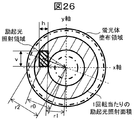
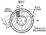
- FIG. 26 is a diagram for explaining the irradiation area per one rotation of the phosphor wheel of the excitation light irradiated on the phosphor wheel in the present embodiment.
- FIG. 26 shows the relationship among the excitation light irradiation region, the phosphor coating region on the phosphor wheel, and the excitation light irradiation area per one rotation of the phosphor wheel.
- the excitation light irradiated onto the phosphor wheel by the array lenses 101 and 102 described above forms a rectangular image similar to the lens cell of the array lens 101 and is irradiated as an excitation light irradiation region.
- the excitation light irradiation area on the phosphor wheel has a rectangular vertical length, that is, a length in the y-axis direction, and a horizontal length, that is, a length in the x-axis direction, h.
- the x axis is the horizontal direction of the projector having the light source device as shown in FIG. 24, and similarly, the y axis corresponds to the vertical direction of the projector.
- r0 be the distance between the rectangular center of the excitation light irradiation region and the center of the phosphor wheel.
- the irradiation area per one rotation of the phosphor wheel is a circle with a radius r2 between the point farthest from the center of the phosphor wheel and the center of the phosphor wheel on the rectangle of the excitation light irradiation region, and on the rectangle.
- the point closest to the center of the phosphor wheel on the rectangle defining the distance r1 is on the vertex or side of the rectangle.
- the point farthest from the center of the phosphor wheel on the rectangle defining the distance r2 is always at the vertex of the rectangle.
- the irradiation density of light becomes smaller as the irradiation area per rotation time of the phosphor wheel is larger, and the irradiation area per rotation time of the phosphor wheel is smaller.
- the irradiation density of light increases. Therefore, by devising the arrangement of the excitation light irradiation region so that the irradiation area per rotation of the phosphor wheel becomes larger, it is possible to suppress a decrease in phosphor conversion efficiency due to luminance saturation.
- FIG. 27 is a diagram for explaining an example of the arrangement of the irradiation region of the excitation light irradiated on the phosphor wheel in the present embodiment. Specifically, per one rotation of the phosphor wheel of the excitation light irradiated on the phosphor wheel. It is a figure explaining the case where the irradiation area of becomes maximum.
- r0 is constant, as shown in FIG. 27, when configured so that the extension line from the center of the phosphor wheel and the diagonal line of the rectangular excitation light irradiation region overlap (substantially match), r1 becomes the smallest, r2 is the largest.
- the irradiation area per rotation of the phosphor wheel can be maximized, and the irradiation density of the excitation light becomes the smallest. Therefore, by configuring as shown in FIG. 27, it is possible to most effectively suppress a decrease in phosphor conversion efficiency due to luminance saturation.
- FIG. 28 is a diagram for explaining the coordinate system of the phosphor wheel and the divided areas of the phosphor coating area in the present embodiment.
- (a) shows the coordinate system of the phosphor wheel and the phosphor coating area.
- (B) shows a diagram in which the phosphor coating area is divided into 16 (areas AP).
- the x-axis horizontal direction of the projector having the light source device
- the y-axis vertical direction of the projector having the light source device
- the center o of the phosphor wheel is the center. If the angle ⁇ with the counterclockwise direction being positive with respect to the x-axis is defined, each region shown in (b) is as follows.
- Region A is a region with an angle of 0 to 22.5 ° of the phosphor coating region of the phosphor wheel.
- Region B is a region having an angle of 22.5 ° to 45 ° in the phosphor coating region of the phosphor wheel.
- Region C is a region having an angle of 45 to 67.5 ° of the phosphor coating region of the phosphor wheel.
- Region D is a region where the angle is 67.5 to 90 ° among the phosphor coating region of the phosphor wheel,
- Region E is a region having an angle of 90 to 112.5 ° of the phosphor coating region of the phosphor wheel.
- Region F is a region with an angle of 112.5 to 135 ° in the phosphor coating region of the phosphor wheel
- region G is a region with an angle of 135 to 157.5 ° in the phosphor coating region of the phosphor wheel
- Region H is a region having an angle of 157.5 to 180 ° in the phosphor coating region of the phosphor wheel
- region I is a region having an angle of 180 to 202.5 ° in the phosphor coating region of the phosphor wheel
- Region J is a region having an angle of 202.5 to 225 ° in the phosphor coating region of the phosphor wheel
- region K is a region having an angle of 225 to 247.5 ° in the phosphor coating region of the phosphor wheel.
- Region L is a region having an angle of 247.5 to 270 ° in the phosphor coating region of the phosphor wheel
- region M is a region having an angle of 270 to 292.5 ° in the phosphor coating region of the phosphor wheel
- Region N is a region having an angle of 292.5 to 315 ° in the phosphor coating region of the phosphor wheel
- region O is a region having an angle of 315 to 337.5 ° in the phosphor coating region of the phosphor wheel.
- the region P is a region having an angle of 337.5 to 360 ° in the phosphor coating region of the phosphor wheel.
- FIG. 29A, FIG. 29B, and FIG. 29C are diagrams for explaining an example of the arrangement of the excitation light irradiation region that irradiates the phosphor wheel.
- the fluorescence is determined by the rectangular shape of the excitation light irradiation region in this embodiment. It is a figure explaining the excitation light irradiation area
- 29A shows a case where the rectangle of the excitation light irradiation region is h ⁇ v
- FIG. 29C shows the excitation light irradiation region. The case where a rectangle is h> v is shown.
- the rectangle of the excitation light irradiation region in FIG. 29A is h ⁇ v.
- the excitation light irradiation region in FIG. 29A is laid out in the vicinity of the y axis, the excitation is in the vicinity of the x axis.
- the distance r1 is small and the distance r2 can be large.
- the rectangle of the excitation light irradiation region is h ⁇ v
- the vicinity of the position where the extension line from the center of the phosphor wheel and the diagonal line of the rectangular excitation light irradiation region overlap and the range where the rectangle is located on the y-axis side are matched.
- Range specifically, the position of the excitation light irradiation region, the position where the center of the rectangle is in the region C, D, E, F, K, L, M, N (the center of the rectangle is the phosphor
- the center of the rectangle is the region A, B, G, H, I, or the like in the phosphor coating region of the wheel at a position where the angle is 45 ° to 135 ° or 225 ° to 315 °.
- the irradiation area per rotation of the phosphor wheel can be increased, the irradiation density of the excitation light can be reduced, and fluorescence due to luminance saturation. To effectively reduce the conversion efficiency of the body Kill.
- the extension line from the center of the phosphor wheel and the diagonal line of the rectangular excitation light irradiation region If the excitation light irradiation region is laid out in the vicinity of 45 °, 135 °, 225 °, and 315 °, which is near the position where the two overlap, the distance r1 is larger than that in the case where the excitation light irradiation region is laid out in the vicinity of the x axis and y axis Is small and the distance r2 can be increased.
- the position of the excitation light irradiation region is the center of the rectangle in the regions B, C, F, G, J, K, N, and O.
- the center of the rectangle is at an angle of 22.5 ° to 67.5 °, 112.5 ° to 157.5 °, 202.5 ° to 247. of the phosphor coating region of the phosphor wheel).
- the center of the rectangle is within the regions A, D, E, H, I, L, M, and P.
- the irradiation area per rotation of the phosphor wheel can be increased, the irradiation density of excitation light can be reduced, and the conversion efficiency of the phosphor due to luminance saturation is effectively reduced. Can be suppressed.
- the rectangle of the excitation light irradiation region is h> v
- the vicinity of the position where the extension line from the center of the phosphor wheel and the diagonal line of the rectangular excitation light irradiation region overlap and the range where the rectangle is located on the x-axis side are matched.
- Range specifically, the position of the excitation light irradiation region such that the center of the rectangle is in regions A, B, G, H, I, J, O, P (the center of the rectangle is the phosphor wheel).
- the rectangular center is the region C, D, E by setting the angle to 0 ° to 45 ° or 135 ° to 225 ° or 315 ° to 360 °.
- the irradiation area per one rotation of the phosphor wheel can be increased and the irradiation density of the excitation light can be reduced. Reduces phosphor conversion efficiency due to brightness saturation It is possible to suppress.
- the generation lens for generating the excitation light having the rectangular shape is provided, and the arrangement of the excitation light irradiation region having the rectangular shape is limited to thereby reduce the excitation light per one rotation of the phosphor wheel.
- the irradiation area can be increased, the irradiation density of the excitation light can be reduced, and a decrease in phosphor conversion efficiency due to luminance saturation can be effectively suppressed.
- the light source device of this embodiment described above can be applied not only to the optical system of the projector of Embodiment 1, but also to any of Embodiments 2, 3, 4, 5, 6, and 7. is there.
- the characteristics of the dichroic mirror 24 are changed to the characteristics of the dichroic mirrors of FIGS.
- the arrangement of the diffusion plate 26 may be matched with the arrangement of the diffusion plates shown in FIGS. 5, 7, and 10
- the arrangement of the phosphor wheel 28 may be matched with the arrangement of the phosphor wheels shown in FIGS.
- optical system 2: light source device, 3: illumination optical system, 4: color separation optical system, 6R, 6G, 6B: image display element, 7: light combining prism, 8: projection lens, 21, 21-1, 21 -2, 21-3: light source, 22, 23: lens, 24, 91, 92, 93: dichroic mirror, 25, 27: condenser lens, 26: diffuser plate, 28: phosphor wheel, 29: motor, 101, 102: Array lens
Landscapes
- Physics & Mathematics (AREA)
- General Physics & Mathematics (AREA)
- Engineering & Computer Science (AREA)
- Multimedia (AREA)
- Optics & Photonics (AREA)
- Signal Processing (AREA)
- Astronomy & Astrophysics (AREA)
- Spectroscopy & Molecular Physics (AREA)
- Projection Apparatus (AREA)
- Non-Portable Lighting Devices Or Systems Thereof (AREA)
- Video Image Reproduction Devices For Color Tv Systems (AREA)
Abstract
より好適にレーザ光源から白色光を生成し画像表示に用いるプロジェクタを提供する。 プロジェクタの白色光生成部が、青色レーザの青色光から矩形形状の励起光を生成する矩形光生成レンズと、励起光が照射され黄色光を発光する蛍光体が塗布される蛍光体ホイールを有し、蛍光体ホイールにおいて、水平方向をx軸、垂直方向をy軸、x軸を基準に反時計回りを正とする角度θを定義し、励起光の照射領域の矩形形状が垂直にv、水平にhの長さであるとき、h<vであり矩形形状の中心が蛍光体塗布領域のうち角度45°以上135°以下または225°以上315°以下の何れか、または、h>vであり角度0°以上45°以下、135°以上225°以下、または315°以上360°以下の何れか、または、h=vであり角度22.5°以上67.5°以下、112.5°以上157.5°以下、202.5°以上247.5°以下、または292.5°以上337.5°以下の何れかの領域にあるように配置する。
Description
本発明は、レーザ光源を利用したプロジェクタに関する。
光源にレーザを用いたプロジェクタの背景技術として、特許文献1がある。特許文献1では、レーザ光源からの青色光と赤色光及び緑色光を含む黄色の蛍光とを用いて生成した白色光を画像表示に用いるプロジェクタが開示されており、青色レーザ光源を2カ所必要とし、第1の青色レーザ光源からの青色光を反射し、第2の青色レーザ光源からの光を励起光として蛍光板から射出された黄色蛍光を透過するダイクロイックミラーを用いて、青色光と黄色蛍光を合成して白色光を生成する点が開示されている。
特許文献1では、異なる2カ所の位置に青色レーザを配置する必要があり、コストが高く、さらに光源装置が大きくなるという課題について考慮されていない。
本発明は、より好適にレーザ光源から白色光を生成するプロジェクタを提供すること目的とする。
本発明は、上記背景技術及び課題に鑑み、その一例を挙げるならば、プロジェクタであって、光源に青色レーザを使用し、前記青色レーザに基づいて青色光と黄色光とを生成し、生成した青色光と黄色光を含む白色光を生成する白色光生成部と、前記白色光生成部で生成した白色光に基づく光を映像表示素子で変調し、変調した光を投射する光学系と、を備え、前記白色光生成部は、少なくとも、前記光源である青色レーザからの青色光から矩形形状の励起光を生成する矩形光生成レンズと、前記矩形形状の励起光が照射され、黄色光を発光する蛍光体が塗布されている蛍光体ホイールと、を有し、前記蛍光体ホイールにおいて、プロジェクタの水平方向をx軸、プロジェクタの垂直方向をy軸とし、蛍光体ホイールの中心oを中心とし、x軸を基準に反時計回りを正とする角度θを定義し、前記蛍光体ホイールに照射する矩形形状の励起光の照射領域の矩形形状のy軸方向の長さをvとし、x軸方向の長さをhとするとき、前記蛍光体ホイールに照射する矩形形状の励起光の照射領域がh<vであり、前記矩形形状の中心が前記蛍光体ホイールの蛍光体塗布領域のうち角度45°以上135°以下の領域または225°以上315°以下の領域のいずれかの領域にあるように配置する、または、前記蛍光体ホイールに照射する矩形形状の励起光の照射領域がh>vであり、前記矩形形状の中心が前記蛍光体ホイールの蛍光体塗布領域のうち角度0°以上45°以下の領域、135°以上225°以下の領域、または315°以上360°以下の領域のいずれかの領域にあるように配置する、または、前記蛍光体ホイールに照射する矩形形状の励起光の照射領域がh=vであり、前記矩形形状の中心が前記蛍光体ホイールの蛍光体塗布領域のうち角度22.5°以上67.5°以下の領域、112.5°以上157.5°以下の領域、202.5°以上247.5°以下の領域、または292.5°以上337.5°以下の領域のいずれかの領域にあるように配置する。
本発明によれば、より好適にレーザ光源から白色光を生成し、画像表示に用いるプロジェクタを提供することができる。
以下、本発明に係る実施例について、図面を参照して説明する。
図1は、本実施例におけるプロジェクタの光学系を示す構成図である。図1において、プロジェクタの光学系1は、主として、光源装置2と、照明光学系3と、色分離光学系4と、映像表示素子6R、6G、6Bと、合成光学系である光合成プリズム7と、投射光学系である投射レンズ8とを備えている。
図1を用いて、プロジェクタの光学系の全体の動作を説明する。光源装置2については、後述するが、光源装置2からは、青色光B(青色帯域の光、以下「B光」とも称する。)と蛍光Y(以下、黄色光「Y光」とも称する。)とが加算されたB+Y光である白色光W光束群(なお白色光Wは、以下「W光」とも称する。)が得られる。ここで、蛍光Yとは、緑色帯域の光と赤色帯域の光も含む黄色蛍光である。白色光W光束群は、照明光学系3のマルチレンズ31の複数のレンズセルにより複数の光に分割され、効率よく第2のマルチレンズ32と偏光変換素子33に導かれる。そして、偏光変換素子33により、光が所定の偏光方向に偏光される。偏光された光は、集光レンズ34により集光され、色分離光学系4に入射する。
色分離光学系4では、まず、ダイクロイックミラー41Bに照射され、照射された白色光Wのうち、青色光B(青色帯域の光)が反射され、緑色光G(緑色帯域の光、以下「G光」とも称する。)及び赤色光R(赤色帯域の光、以下「R光」とも称する。)が透過する。反射されたB光は、反射ミラー42Aにより反射されコンデンサレンズ5Bを透過して映像表示素子6Bに入射される。一方、ダイクロイックミラー41Bを透過したG光及びR光は、ダイクロイックミラー41Gにより、G光が反射され、R光が透過する。反射されたG光は、コンデンサレンズ5Gを透過して映像表示素子6Gに入射される。また、ダイクロイックミラー41Gを透過したR光は、リレーレンズ43により集光され、その後反射ミラー42Bにより反射される。反射されたR光は、再びリレーレンズ44により集光され、反射ミラー42Cにより反射される。反射されたR光は、さらにリレーレンズ5Rによって集光され映像表示素子6Rに入射される。各映像表示素子では入射光に対して、映像信号(図示なし)に応じて画素ごとに光強度変調して映像を形成し、反射または透過による出射光を生成する。なお、図1の例では、透過型の映像表示素子の例を開示している。各映像表示素子を出射したB光、G光、R光は光合成プリズム7によってカラー映像光として合成され、投射レンズ8を透過した後、スクリーン(図示なし)に到達する。すなわち、映像表示素子により形成された光学像がスクリーン(図示なし)上に拡大投影される。
次に、図2Aを用いて、本実施例における光源装置2の詳細説明を行う。図2Aは、図1の光源装置2の部分を抜き出し、さらに、ダイクロイックミラー24の持つ透過/反射特性を示した概念図を光軸1に対応した位置に図示している。図2Aにおいて、光源21は青色レーザ(BL)であり、光軸1を中心として、青色レーザ光(B光)が出射される。そして、レンズ22により、B光束が集光されながら重畳され、レンズ23によってB光束が平行な光束になる。そして、ダイクロイックミラー24にB光束が照射される。
ここで、ダイクロイックミラー24は、図示したようなB透過/Y反射の特性の領域を有し、かつ、全反射領域をダイクロイックミラーの中央部に備えている。すなわち、ダイクロイックミラー24は、B光透過Y光反射の特性の領域が広い。しかし、部分的に当該B光透過Y光反射の特性とは異なる全反射特性の領域を有するものである。本発明の以下の説明において、透過/反射特性が領域分割されたダイクロイックミラーが備える領域のうち、広範囲を占める特性の領域を以下、「広域特性領域」と称する。また、部分的な狭い領域において、前記「広域特性領域」の特性と異なる領域を以下、「異特性領域」と称する。図2Aの例では、B透過/Y反射の特性の領域が「広域特性領域」であり、全反射領域が「異特性領域」である。なお、「広域特性領域」内のB光透過・反射特性は完全に一様でもよいが、左右の光の入射角度に依存する色ムラを解消するために、ダイクロイックコートのカット波長(例えば50%波長)を左右方向で傾斜をつけてもよい。この場合は、本発明の各実施例の説明では、カット波長の傾斜がついていても、同じ「広域特性領域」に属すると考える。また、本発明の各実施例の説明では「異特性領域」は、全反射特性か全透過特性を有する例を説明するが、本発明に影響が少ない範囲で、なんらかの理由によりダイクロイックコートを用いる可能性もある。その場合も「異特性領域」内で、透過・反射特性は完全に一様でもよいが、左右の光の入射角度に依存する色ムラを解消するために、ダイクロイックコートのカット波長(例えば50%波長)を左右方向で傾斜を設定してもよい。この場合も、カット波長の傾斜が設定されていても、同じ「異特性領域」に属すると考える。
例えば、一例として、光源21からダイクロイックミラーに照射されるB光領域のうち、異特性領域である全反射領域の割合が入射光束の照射範囲の20%とする場合を説明すると、ダイクロイックミラー24に照射されたB光束は、20%程度が反射され、80%程度が透過する。すなわち、光源21からダイクロイックミラー24に照射されるB光束のうち、B光束中央部の20%程度が反射される。
ダイクロイックミラー24によって反射されたB光束は、コンデンサレンズ25により集光されて拡散板26に照射される。そして、コンデンサレンズ25の光軸である光軸2を中心として、拡散板26により拡散されたB光束は、コンデンサレンズ25を透過して、ダイクロイックミラー24に照射される。この時、ダイクロイックミラー24に照射されるB光束の面積は、光源21からダイクロイックミラー24に照射されるB光束の面積よりも大きい。そして、拡散板26からダイクロイックミラー24に照射されるB光束のうち、例えば、拡散板によるB光入射領域の面積拡大率が2の場合、一例として、異特性領域の形状により10%程度が反射されてしまうが90%程度を透過させることが可能である。
一方、光源21からダイクロイックミラー24に照射されるB光束のうち、ダイクロイックミラー24を透過するB光束はコンデンサレンズ27により集光されて蛍光体ホイール28に照射される。蛍光体ホイール28はB光を励起光としてY光を発光する蛍光体が塗布されており、焼き付け防止のためにモータ29により回転している。そして、光軸1を中心として、蛍光体ホイール28からY光が発光し、コンデンサレンズ27を透過してダイクロイックミラー24に照射される。そして、ダイクロイックミラー24によりY光束が反射され、B光束と重なりB+Y光束であるW光束となる。
なお、図2Bに本実施例に係る青色レーザの発光スペクトルの一例を示す。また、図2Cに本実施例に係る黄色蛍光体の発光スペクトルの一例を示す。
このように、本実施例における光源装置2は、光源21に青色レーザを使用し、B(青)+Y(黄)の光を合成することにより、白色光Wを生成する。つまり、光源装置2は、白色光生成部ともいえる。また、ダイクロイックミラー24は、広域特性領域としてB透過/Y反射の特性の領域を設け、かつ、異特性領域として全反射領域をダイクロイックミラー中央部に備えている。そして、拡散板26によりB光を拡散させ、B光の面積を拡大させる。これにより、白色光Wに含まれない光であるB光の光源21への戻り光の面積比を小さくすることが可能になり、B光利用率を増加させることができる。
次に、図4を用いて、本実施例におけるダイクロイックミラー24の広域特性領域であるB透過Y反射領域と異特性領域である全反射領域のコーティング方法の一例と、各領域の透過率特性の一例を説明する。図4(a)が平面図、(b)が断面図、(c)がB透過Y反射領域の透過率特性、(d)が全反射領域の透過率特性である。図4(b)に示すように、ダイクロイックミラー24はガラス基板の片面にB透過Y反射特性のダイクロイックコーティングを施し、反対面にARコーティング(Anti Reflective Coating:反射防止コーティング)を施し、その上に全反射領域用のミラーコーティングを施すことで製造できる。そして、各領域の透過率特性は、図4(c)に示すように、広域特性領域であるB透過Y反射領域では、B光の波長である455nm近辺は透過率は少なくとも95%以上であり限りなく100%に近いことが望ましい、Y光に含まれる500から700nm近辺の緑色帯域から赤色帯域の光の透過率は少なくとも5%以下であり限りなく0%に近いことが望ましい。また、異特性領域である全反射領域は、図4(d)に示すように、全波長領域で透過率は少なくとも5%以下であり、限りなく0%であることが望ましい。
すなわち、本発明の各実施例において、B光透過Y光反射特性とは、B光の波長である455nm近辺は透過率が少なくとも95%以上であり、Y光に含まれる500から700nm近辺の緑色帯域から赤色帯域の光の反射率が少なくとも95%以上であることを意味する。同様に、本発明の各実施例において、B光反射Y光透過特性とは、B光の波長である455nm近辺は反射率が少なくとも95%以上であり、Y光に含まれる500から700nm近辺の緑色帯域から赤色帯域の光の透過率が少なくとも95%以上であることを意味する。
また、本発明の各実施例において、全透過特性とは、少なくとも青色帯域455nm近辺から赤色帯域である700nmまでの全波長領域の透過率が少なくとも95%以上であることを意味する。同様に、本発明の各実施例において、全反射特性とは、少なくとも青色帯域455nm近辺から赤色帯域である700nmまでの全波長領域の反射率が少なくとも95%以上であることを意味する。
なお、以下の説明で光利用率などの計算を行う際には、計算を簡単にするために、所定の帯域の光を反射する特性の場合は100%反射、所定の帯域の光を透過する特性の場合は100%透過として計算する。
なお、本発明の各実施例において、「広域特性領域」においては、B光とY光の透過特性および反射特性は、逆となるように構成される。すなわち、「広域特性領域」においてB光透過の特性がある場合は、Y光は反射特性があるように構成され、結果的に当該「広域特性領域」の特性は、B光透過Y光反射特性と設定される。また、「広域特性領域」においてB光反射の特性がある場合は、Y光は透過特性があるように構成され、結果的に当該「広域特性領域」の特性は、B光反射Y光透過特性と設定される。
なお、本発明の各実施例において、「異特性領域」においては、B光とY光の透過特性および反射特性は、同じになるように構成される。すなわち、「異特性領域」においてB光透過の特性がある場合は、Y光も透過特性があるように構成され、結果的に当該「異特性領域」の特性は、全透過特性と設定される。また、「異特性領域」においてB光反射の特性がある場合は、Y光も反射特性があるように構成され、結果的に当該「異特性領域」の特性は、全反射特性と設定される。
次に、図3を用いて、本実施例に係る構成によるB光利用率高効率化の原理を説明する。図3において、(a)は本実施例による構成(透過/反射特性の領域分割および拡散板)を採用しない場合、(b)は本実施例による透過/反射特性の領域分割および拡散板ありの光源装置の光学系の一例である。
図3(a)の構成は、ダイクロイックミラー24の透過/反射特性が領域全体で一様であり、B光反射率をR1、B光透過率をT1であるとする。この場合、B光の入射光に対するB出射光(本図ではB透過光)の割合であるB光利用率E1は、R1×(1-R1)=(R1×T1)となり、例えば、 ダイクロイックミラー24に入射するB光のうち20%を反射させ、80%を透過させる設定であるR1=0.2、T1=0.8とすると、B光利用率E1[%]=0.2×(1-0.2)×100=16[%]となる。
一方、本実施例に係る図3(b)の構成の場合は、図3(c)に示すように、B入射光の入射領域Iの面積をSI、B拡散光の入射領域Oの面積をSO、B入射光の入射領域Iのうち異特性領域である全反射領域WI(B光の反射特性R≒1となる)の面積をSWI、B拡散光の入射領域Oのうち異特性領域である全反射領域WO(B光反射特性R≒1となる)の面積をSWOとする。このとき、レーザ光源からのB入射光に対する反射光の割合であるダイクロイックミラー24でのB入射光実質反射率R2はSWI/SIから算出できる。また、B拡散光に対する透過の割合であるダイクロイックミラー24でB拡散光実質透過率T2は(SO-SWO)/SOから算出できる。B光利用率E2は、R2×T2=(SWI/SI)×((SO-SWO)/SO)となる。ここで、SWI/SIはレーザ光源からダイクロイックミラーに入射するB光の利用効率と表現することもできる。また、(SO-SWO)/SOは、B拡散光からダイクロイックミラーに入射するB光の利用効率と表現することもできる。
ここで、 図3(a)の構成と図3(b)の構成の効率を比較するために、図3(a)のB光反射率R1と図3(b)のB入射光実質反射率R2の設定を等しくした場合を考える。この時、E2>E1となるための条件は、R2×T2>R1×(1-R1)である。ここで、R1にR2を代入すると、R2×T2>R2×(1-R2)となる。両辺をR2で除算すると、T2>1-R2となる。これは、(SO-SWO)/SO>(SI-SWI)/SIと変形できる。両辺にSOを乗ずると、SO-SWO>(SI-SWI)×SO/SIとなる。SO/SIを拡散光の入射領域の面積拡大率としてαとおくと、SO-SWO>SO-SWI×αとなり、SWI×α>SWOに変形できる。これはSWO/SWI<αと変形でき、SWO/SWI=βとおけば、α>βとなる。この式の意味としては、B入射光の入射領域I内の異特性領域の大きさであるSWIに対するB拡散光の入射領域Oのうちの異特性領域の大きさであるSWOの比βが拡散光の入射領域の面積拡大率αよりも大きくならないように、ダイクロイックミラー24における異特性領域の形状を設定することで、B光の利用率について、図3(b)の構成の効率を図3(a)の構成の効率より高めることができることを意味している。B光利用率E2をαとβを用いた式で表すと、E2=R2×T2=R2×(1-(R2×β/α))となる。すなわち、本実施例に係る図3(b)の構成では、ダイクロイックミラー24の出射までのB光利用率だけを考慮すれば、拡散光の入射領域の面積拡大率αは大きければ大きいほど効率が良く、B入射光の入射領域I内の異特性領域の大きさであるSWIに対するB拡散光の入射領域Oのうちの異特性領域の大きさであるSWOの比βは小さければ小さいほどよいことになる。
具体的には、例えば、R2=SWI/SI=0.2、拡散光の入射領域の面積拡大率α=SO/SI=2とし、異特性領域の形状がβ=SWO/SWIが1.2となる形状である場合、B光利用率E2[%]=0.2×(1-(0.2×1.2/2))×100=17.2[%]となり、より大となる。
これは、R1=0.2とした場合の図3(a)の構成のB光利用率E1[%]=16[%]よりも大きくなる。
このように、本実施例によれば、光源21に青色レーザを使用し、B+Yの光を合成することにより、白色光を生成する光源装置において、ダイクロイックミラー24を、広域特性領域であるB透過/Y反射の特性領域を有し、かつ異特性領域である全反射領域を中央部に備えて、透過/反射特性が領域分割された構成とし、拡散板26によりB光を拡散させ、B光の面積を拡大させることで、B光利用率を増加させることができる。
以上説明したように本実施例によれば、より好適にレーザ光源から白色光を生成し、画像表示に用いるプロジェクタを実現することが可能となる。
本実施例は、実施例1のプロジェクタにおいて、光源装置のダイクロイックミラーへのコーティング仕様を変更し、それにともない、蛍光体ホイール及び拡散板の配置を変更した例である。
なお、説明を簡単にするため、本実施例の説明においては、実施例1からの変更点のみ説明するものとし、特に記載が無い構成及び動作については実施例1と同様であるものとする。特に、光源装置においてB+Y光である白色光W光を生成した後の、プロジェクタの光学系及び映像表示素子の構成および動作は実施例1の図1と同様であるため、説明を省略する。
図5は、本実施例におけるプロジェクタの光源装置の構成図およびダイクロイックミラーの透過/反射特性を示す図である。図5において、図2Aと同じ機能を有する構成には同じ符号を付し、その説明は省略する。図5において、図2Aと異なる点は、ダイクロイックミラーの透過/反射特性が異なる点と、蛍光体ホイール及び拡散板の位置が入れ替わっている点である。
図5において、レンズ23によって略平行とされたB光束がダイクロイックミラー91に照射される。ここで、ダイクロイックミラー91は、図示したように、広域特性領域であるB反射/Y透過の特性領域を有し、かつ、異特性領域である全透過領域をダイクロイックミラーの中央部に備えている。すなわち、ダイクロイックミラー91は、広域特性領域であるB光反射Y光透過の特性の領域が広いが、部分的に当該B光反射Y光透過の特性とは異なる全透過特性の領域(異特性領域)を有するものである。例えば、一例として、光源21からダイクロイックミラーに照射されるB光領域のうち、全透過領域の割合を全体の20%とする場合を説明すると、ダイクロイックミラー91に照射されたB光束は、80%程度が反射され、20%程度が透過する。すなわち、光源21からダイクロイックミラー91に照射されるB光束のうち、B光束中央部の20%程度が透過される。このように実施例2は実施例1とダイクロイックミラーの透過反射特性が異なるが、所定の透過反射特性領域を有する広域特性領域と部分的に当該所定の透過反射特性とは異なる異特性領域を同一のダイクロイックミラーに有するという点で概念が共通している。
ダイクロイックミラー91により反射されたB光束はコンデンサレンズ27により集光されて蛍光体ホイール28に照射される。コンデンサレンズ27の光軸である光軸2を中心として、蛍光体ホイール28からY光が発光し、コンデンサレンズ27を透過してダイクロイックミラー91に照射され、Y光束がダイクロイックミラー91を透過する。
一方、光源21からダイクロイックミラー91に照射されるB光束のうち、ダイクロイックミラー91を透過したB光束は、コンデンサレンズ25により集光されて拡散板26に照射される。光軸1を中心として、拡散板26により拡散されたB光束は、コンデンサレンズ25を透過して、ダイクロイックミラー91に照射される。この時、ダイクロイックミラー91に照射されるB光束の面積は、光源21からダイクロイックミラー91に照射されるB光束の面積よりも大きい。拡散板26からダイクロイックミラー91に照射されるB光束のうち、例えば、拡散板によるB光入射領域の面積拡大率が2の場合、一例として、異特性領域の形状により10%程度が透過されてしまうが90%程度を反射させることが可能である。そして、ダイクロイックミラー91により反射されたB光束が、Y光束と重なりB+Y光束となる。これにより、実施例2の構成によっても実施例1と同程度に、B光利用率を増加させることができる。
図6は、本実施例におけるダイクロイックミラー91のB反射Y透過領域と全透過領域のコーティング方法と、各領域の透過率特性を示す図である。図6(a)が平面図、(b)が断面図、(c)がB反射Y透過領域の透過率特性、(d)が全透過領域の透過率特性である。図6(b)に示すように、ダイクロイックミラー91はガラス基板の片面にARコーティングを施し、反対面にB反射Y透過特性のダイクロイックコーティングと、全透過領域用のARコーティングを施すことで製造できる。そして、各領域の透過率特性は、図6(c)に示すように、広域特性領域であるB反射Y透過領域では、B光の波長である455nm近辺は透過率は少なくとも5%以下であり、限りなく0%に近いことが望ましい、Y光に含まれる500から700nm近辺の緑色帯域から赤色帯域の光の透過率は少なくとも95%以上であり限りなく100%に近いことが望ましい。また、異特性領域である全透過領域は、図6(d)に示すように、全波長領域で透過率が少なくとも95%以上であり、限りなく100%であることが望ましい。
なお、本実施例の構成においてB光利用率が高効率化の原理と条件の詳細は、実施例1の図3の説明において、B光の「透過」を「反射」に置き換え、「全反射」を「全透過」に置き換えればよい。具体的には図3(c)のB入射光の入射領域Iの面積をSI、B拡散光の入射領域Oの面積をSO、B入射光の入射領域Iのうち異特性領域である全透過領域WI(B光の透過特性T≒1となる)の面積をSWI、B拡散光の入射領域Oのうち異特性領域である全透過領域WO(B光透過特性T≒1となる)の面積をSWOとする。このとき、レーザ光源からのB入射光に対する透過光の割合であるダイクロイックミラー91でB入射光実質透過率T3はSWI/SIから算出できる。また、B拡散光に対する透過の割合であるダイクロイックミラー91でB拡散光実質反射率R3は(SO-SWO)/SOから算出できる。実施例2の光源装置におけるB光利用率E3は、T3×R3=(SWI/SI)×((SO-SWO)/SO)となる。つまり、実施例1に対してB光の反射特性と透過特性が反対になったとしても、当該光源装置のB光利用率E3は、レーザ光源からダイクロイックミラーに入射するB光の利用効率(SWI/SI)と、B拡散光からダイクロイックミラーに入射するB光の利用効率((SO-SWO)/SO)の積であることに変わりはない。
すると本実施例の当該光源装置のB光利用率E3も実施例1E2の式変形と同様に、SO/SIを拡散光の入射領域の面積拡大率αとB入射光の入射領域I内の異特性領域の大きさであるSWIに対するB拡散光の入射領域Oのうちの異特性領域の大きさであるSWOの比βを用いることで、E3=T3×R3=T3×(1-(T3×β/α))と表現できる。
すなわち、本実施例に係る構成においても、ダイクロイックミラー91の出射までのB光利用率だけを考慮すれば、拡散光の入射領域の面積拡大率αは大きければ大きいほど効率が良く、B入射光の入射領域I内の異特性領域の大きさであるSWIに対するB拡散光の入射領域Oのうちの異特性領域の大きさであるSWOの比βは小さければ小さいほどよいことになる。
このように、本実施例によれば、光源21に青色レーザを使用し、B+Yの光を合成することにより白色光を生成する光源装置において、ダイクロイックミラー91を、広域特性領域であるB反射/Y透過の特性領域を有し、かつ異特性領域である全透過領域を中央部に備えて、透過/反射特性が領域分割された構成とし、拡散板26によりB光を拡散させ、B光の面積を拡大させることで、B光利用率を増加させることができる。
以上説明したように本実施例によれば、実施例1と異なる構成でも、実施例1と同程度に、より好適にレーザ光源から白色光を生成し、画像表示に用いるプロジェクタを実現することが可能となる。
本実施例は、実施例1のプロジェクタにおいて、光源装置におけるダイクロイックミラーにおける異特性領域をコンデンサレンズ25の光軸である光軸2とダイクロイックミラーが接する中央部からオフセットした位置に配置する例について説明する。
図7は、本実施例における光源装置の構成図およびダイクロイックミラーの透過/反射特性を示す図である。図7において、図2Aと同じ機能を有する構成には同じ符号を付し、その説明は省略する。
実施例1の図2Aにおいてダイクロイックミラーにおける異特性領域の位置は光軸2とダイクロイックミラーが接する中央部付近に配置したのに対し、本実施例の図7においては、異特性領域の位置を光軸2とダイクロイックミラーが接する中央部からオフセットした位置としている。
異特性領域の位置を光軸2とダイクロイックミラーが接する中央部からオフセットした位置をこのように変更するためには、単に、B色レーザ光源21からのB光入射光が入射する範囲で、異特性領域を光軸2とダイクロイックミラーが接する中央部からオフセットした位置に配置するだけでも良い。また、B色レーザ光源21の光軸1を、コンデンサレンズ25の光軸2とダイクロイックミラーに対して鏡面配置の関係にある光軸3からオフセットして配置することによりさらに異特性領域を光軸2からオフセットして配置することができる。図7では一例として、レーザ光源21の光軸1のオフセットと異特性領域の中央部からのオフセットの両者を採用した例を示している。
図7において、レンズ23によって平行とされたB光束がダイクロイックミラー92に照射される。ここで、ダイクロイックミラー92は、図示したように、広域特性領域であるB透過/Y反射の特性領域を有し、かつ、異特性領域である全反射領域を光軸2と接する位置からオフセットした位置に備えている。例えば、光源21からダイクロイックミラーに照射されるB光領域のうち、全反射領域の割合を全体の20%とすると、ダイクロイックミラー92に照射されたB光束は、20%程度が反射され、80%程度が透過する。すなわち、光源21からダイクロイックミラー92に照射されるB光束のうち、B光束の中心からオフセットした部分の20%が反射される。
ダイクロイックミラー92によって反射されたB光束は、拡散板26により拡散され、ダイクロイックミラー92に照射される。この時、ダイクロイックミラー92に照射されるB光束の面積は、光源21からダイクロイックミラー92に照射されるB光束の面積よりも大きい。
次に、拡散板26からダイクロイックミラー92に照射されるB光束のうち、異特性領域で反射される割合と広域特性領域で透過される割合を面積比だけに基づいて計算する。例えば、面積比計算で、拡散板によるB光入射領域の面積拡大率が2の場合、一例として、異特性領域の形状により10%程度が反射され90%程度を透過する構成を考える。ここで、実施例1と異なり、実施例3では、異特性領域の位置を光軸2とダイクロイックミラーが接する中央部からオフセットされている。ここで、図8に、拡散板26から射出する光の照度分布図を示す。図8に示すように、中心位置からずれるほど照度は低下する。すると、実施例3のように異特性領域の位置を光軸2とダイクロイックミラーが接する中央部からオフセットして配置することにより、例え異特性領域の面積が実施例1と同じであっても、拡散板26からのB拡散光のうち、ダイクロイックミラー92で反射されて光源21に戻る部分のB拡散光は、図8の中心角度のピーク強度ではなく、周辺角度の相対的に小さい強度になり、実施例1の図2Aに対し、レーザ光源への戻り光を少なくできる。例えば、このオフセットによる図8の拡散光強度の相対比効果が50%だとすると、拡散板によるB光入射領域の面積拡大率が2で、面積比計算のみで異特性領域の形状により10%程度が反射され90%程度を透過する構成では、拡散板26からダイクロイックミラー92に照射されるB光束は、実際の図8の強度分布を考慮すると、5%程度が反射され、95%程度が透過することとなる。
一方、光源21からダイクロイックミラー92に照射されるB光束のうち、ダイクロイックミラー92を透過するB光束は蛍光体ホイール28に照射される。そして、コンデンサレンズ27の光軸である光軸3を中心として、蛍光体ホイール28からY光が発光し、ダイクロイックミラー92に照射される。そして、ダイクロイックミラー92の広域特性領域によりY光束が反射され、B光束と重なりB+Y光束となる。
図9は、本実施例におけるダイクロイックミラー92の広域特性領域であるB透過Y反射領域と異特性領域である全反射領域のコーティング方法を示す図である。図9(a)が平面図、(b)が断面図である。図9(b)に示すように、ダイクロイックミラー92は、ガラス基板の片面にB透過Y反射特性のダイクロイックコーティングを施し、反対面にARコーティングを施し、その上に全反射領域用のミラーコーティングを施すことで製造できる。
以上説明した本実施例によれば、光源21に青色レーザを使用し、B+Yの光を合成することにより白色光を生成する光源装置において、ダイクロイックミラー92を、広域特性領域であるB透過/Y反射の特性領域を有し、かつ異特性領域である全反射領域をコンデンサレンズ25の光軸である光軸2が接する位置からオフセットして配置して、透過/反射特性が領域分割された構成とし、拡散板26によりB光を拡散させ、B光の面積を拡大させることで、B光利用率を増加させることができる。
以上説明したように本実施例によれば、実施例1よりB光利用率を増加させることが可能となり、より好適にレーザ光源から白色光を生成し、画像表示に用いるプロジェクタを実現することが可能となる。
本実施例は、実施例2のプロジェクタにおいて、光源装置におけるダイクロイックミラーにおける異特性領域を、コンデンサレンズ25の光軸である光軸3とダイクロイックミラーが接する中央部からオフセットした位置に配置する例について説明する。
図10は、本実施例における光源装置の構成図およびダイクロイックミラーの透過/反射特性を示す図である。図10において、図5と同じ機能を有する構成には同じ符号を付し、その説明は省略する。
実施例2の図5においてダイクロイックミラーにおける異特性領域の位置は光軸3とダイクロイックミラーが接する中央部付近に配置したのに対し、本実施例の図10においては、異特性領域の位置を光軸3とダイクロイックミラーが接する中央部からオフセットした位置としている。
異特性領域の位置を光軸2とダイクロイックミラーが接する中央部からオフセットした位置をこのように変更するためには、単に、B色レーザ光源21からのB光入射光が入射する範囲で、異特性領域を光軸3とダイクロイックミラーが接する中央部からオフセットした位置に配置するだけでも良い。また、B色レーザ光源21の光軸1を光軸3からオフセットして配置することによりさらに異特性領域を光軸3からオフセットして配置することができる。図10では一例として、レーザ光源21の光軸1のオフセットと異特性領域の中央部からのオフセットの両者を採用した例を示している。
図10において、レンズ23によって平行とされたB光束がダイクロイックミラー93に照射される。ここで、ダイクロイックミラー93は、図示したように、広域特性領域としてB反射/Y透過の特性の領域を有し、かつ、異特性領域として全透過領域を光軸3と接する位置からオフセットした位置に備えている。例えば、光源21からダイクロイックミラーに照射されるB光領域のうち、異特性領域である全透過領域の割合を全体の20%とすると、ダイクロイックミラー93に照射されたB光束は、80%程度が反射され、20%程度が透過する。すなわち、光源21からダイクロイックミラー93に照射されるB光束のうち、B光束の中心からオフセットした部分の20%程度が透過される。
ダイクロイックミラー93によって反射されたB光束は、蛍光体ホイール28に照射される。コンデンサレンズ27の光軸である光軸2を中心として、蛍光体ホイール28からY光が発光し、ダイクロイックミラー93に照射され、Y光束がダイクロイックミラー93を透過する。
一方、光源21からダイクロイックミラー93に照射されるB光束のうち、ダイクロイックミラー93を透過したB光束は、拡散板26に照射され、コンデンサレンズ25の光軸である光軸3を中心として、拡散板26により拡散されたB光束は、ダイクロイックミラー93に照射される。この時、ダイクロイックミラー93に照射されるB光束の面積は、光源21からダイクロイックミラー93に照射されるB光束の面積よりも大きい。
次に、拡散板26からダイクロイックミラー93に照射されるB光束のうち、異特性領域で透過される割合と広域特性領域で反射される割合を面積比だけに基づいて計算する。例えば、拡散板によるB光入射領域の面積拡大率が2の場合、一例として、異特性領域の形状により10%が透過され90%程度を反射する構成を考える。ここで、実施例2と異なり、本実施例では、異特性領域の位置を光軸3とダイクロイックミラーが接する中央部からオフセットされている。ここで、図8に示したように、拡散板26から射出する光の照度分布は中心位置からずれるほど照度は低下する。すると、実施例3のように異特性領域の位置を光軸3とダイクロイックミラーが接する中央部からオフセットして配置することにより、例え異特性領域の面積が実施例2と同じであっても、拡散板26からのB拡散光のうち、ダイクロイックミラー93で透過されて光源21に戻る部分のB拡散光は、図8の中心角度のピーク強度ではなく、周辺角度の相対的に小さい強度になり、実施例2の図5に対し、レーザ光源への戻り光を少なくできる。例えば、このオフセットによる図8の拡散光強度の相対比効果が50%だとすると、拡散板によるB光入射領域の面積拡大率が2で、面積比計算のみで異特性領域の形状により10%程度が透過され90%程度を反射する構成では、拡散板26からダイクロイックミラー93に照射されるB光束は、実際の図8の強度分布を考慮すると、5%程度が透過され、95%程度が反射することとなる。
そして、ダイクロイックミラー93の広域特性領域により反射されたB光束が、Y光束と重なりB+Y光束となる。
図11は、本実施例におけるダイクロイックミラー93の広域特性領域であるB反射Y透過領域と異特性領域である全透過領域のコーティング方法を示す図である。図11(a)が平面図、(b)が断面図である。図11(b)に示すように、ダイクロイックミラー93はガラス基板の片面にARコーティングを施し、反対面にB反射Y透過特性のダイクロイックコーティングと、全透過領域用のARコーティングを施すことで製造できる。
以上説明した本実施例によれば、光源21に青色レーザを使用し、B+Yの光を合成することにより白色光を生成する光源装置において、ダイクロイックミラー93を、広域特性領域であるB反射/Y透過の特性領域を有し、かつ異特性領域である全透過領域をコンデンサレンズ25の光軸である光軸3が接する位置からオフセットして配置して、透過/反射特性が領域分割された構成とし、拡散板26によりB光を拡散させ、B光の面積を拡大させることで、B光利用率を増加させることができる。
以上説明したように本実施例によれば、実施例2よりB光利用率を増加させることが可能となり、より好適にレーザ光源から白色光を生成し、画像表示に用いるプロジェクタを実現することが可能となる。
本実施例は、実施例1から4で説明した、プロジェクタにおいて、ダイクロイックミラーの透過/反射領域の分割構成と、光源として複数のレーザを用い、それらのレーザの強度を変えることで調光および/または調色を実現する例について説明する。
図12は、本実施例における光源装置の光源部分の概略構成図である。図12は、図2A、図5、図7または図10の光源装置の構成において、光源21の構成の詳細を示したものである。具体的には、光源21として光源21-1、21-2を2つ用いて、それぞれを電源1(20-1)、電源2(20-2)で駆動し、それぞれの電源1、電源2を制御する制御部10を有する。
図13は実施例1(図2Aの構成)及びその変形例に対応したダイクロイックミラーの透過/反射領域の分割構成を示した図である。図13(a)が、実施例1に対応した構成である。図13(a)において、それぞれB透過Y反射領域(広域特性領域M)と全反射領域(異特性領域W)にまたがる領域に、光源21-1からのB光が照射される照射領域E21-1と、光源21-2からのB光が照射される照射領域E21-2とを有する。なお、光源21-1からのB光が照射される照射領域E21-1と、光源21-2からのB光が照射される照射領域E21-2とを合わせた領域が、図3(c)の領域Iに相当する。なお、図13(a)に示すB拡散光入射領域が、図3(c)の領域Oに相当する。
図13(a)の例では、左右対称に領域を配置しており、照射領域E21-1内での広域特性領域Mと異特性領域Wの割合と、照射領域E21-2内での広域特性領域Mと異特性領域Wの割合が同じである。よって、光源21-1、21-2のレーザの強度を変えれば、光源装置2から出力されるB光とY光の比率は変わらないまま、光源装置2から出力される光の強度を調整する調光機能を実現することができる。
図13(b)は、図13(a)の領域分割の変形例であり、図13(a)と異なり、異特性領域Wである全反射領域が紙面の幅方向に広く、かつ光源21-1からのB光が照射される照射領域E21-1と、光源21-2からのB光が照射される照射領域E21-2を合わせた領域(図3(c)の領域Iに相当する)に包含される。図13(b)の例では、異特性領域Wが、領域Iに包含されているので、異特性領域Wが図3(c)の例の領域WIと領域WOの両者に相当する。実施例1で説明したとおり、光源装置2においては、B入射光の入射領域I内の異特性領域の大きさであるSWIに対するB拡散光の入射領域Oのうちの異特性領域の大きさであるSWOの比βは小さければ小さいほど光源装置としてB光利用効率がよい。ここで、異特性領域Wを領域Iに包含させることで、β=1とすることができ、βを最小化することができる。
なお、実施例1で説明した図3(b)の構成のB光利用効率E2は、β/αが1より小さいときには、必ず図3(a)の構成のB光利用効率E1よりも効率が良くなる。すると、異特性領域Wを領域Iに包含させることでβ=1とできれば、コンデンサレンズ25と拡散板26の効果によりαが1より大きくなるので、図3(b)の構成は図3(a)の構成よりもB光利用効率が必ず大きくなる。
すると、図13(b)のように異特性領域Wを領域Iに包含させる構成とすれば、図13(a)のように異特性領域Wが領域Iに包含させない構成よりも、B光利用率を高めることが可能となる。
また、図13(a)の構成では、異特性領域Wが照射領域E21-1と、照射領域E21-2の縦方向の境界線に細長く存在するため、光学部品の組み立て精度などにより、照射領域E21-1と、照射領域E21-2の位置と、ダイクロイックミラーの異特性領域Wの左右方向の相対位置が大きくずれた場合、照射領域E21-1内での広域特性領域Mと異特性領域Wの割合と、照射領域E21-2内での広域特性領域Mと異特性領域Wの割合が大きく変化してしまう。例えば、上記相対位置のずれにより、異特性領域Wである全反射領域に照射されるB光が左右の光源のうち一方のみとなった場合、当該一方のレーザ光源を制御する電源が故障した場合、光源からダイクロイックミラーの入射する光のうち広域特性領域Mを経由した光だけが利用されることになるので、光源装置2からB光かY光のいずれか一方(図13(a)の例では、Y光)のみが出力されることなり、白色光の生成が不可能となる。これに対し、図13(b)の構成であれば、異特性領域Wである全反射領域が幅方向に広いため、上記左右方向の相対位置のズレが生じた場合でも、異特性領域Wである全反射領域に照射されるB光が左右の光源のうち一方のみとなりにくい。
これにより、図13(b)の構成では、一方のレーザ光源を制御する電源が故障した場合でも、光源装置2から出力光がB光かY光のいずれか一方の色になるという現象を回避することができる。
また、図13(c)は、さらに異なる領域分割の変形例である。図13(c)の例では、図13(a)、図13(b)の例と異なり、異特性領域Wである全反射領域が左右で非対称であるように構成する。これにより、照射領域E21-1内での広域特性領域Mと異特性領域Wの割合と、照射領域E21-2内での広域特性領域Mと異特性領域Wの割合とを異ならせている。これにより、光源21-1からのB光が最終的に光源装置2の出力光に寄与するB光とY光の比率と、光源21-2からのB光が最終的に光源装置2の出力光に寄与するB光とY光の比率を異ならせることができる。すると、電源1の制御によって光源21-1の光強度を可変制御したり、または電源2の制御によって光源21-2の光強度を可変制御したりすることにより、光源21-1の光強度と光源21-2の光強度との相対比率を可変することにより、光源装置2が出力する光の色と強度の両者を制御することが可能となる。すなわち、光源装置2から出力される光の調色機能と調光機能を実現することができる。
なお、図13(c)の例では、異特性領域Wが、異特性領域Wが、照射領域E21-1と照射領域E21-2を合わせた領域(領域I)に包含されているので、B光利用率が高いという利点もある。
また、図13(d)は、さらに異なる領域分割の変形例である。図13(d)の例では、図13(c)の例と同様、照射領域E21-1内での広域特性領域Mと異特性領域Wの割合と、照射領域E21-2内での広域特性領域Mと異特性領域Wの割合とを異ならせている。よって、図13(c)の例と同様、電源1の制御によって光源21-1の光強度を可変制御したり、または電源2の制御によって光源21-2の光強度を可変制御したりすることにより、光源21-1の光強度と光源21-2の光強度との相対比率を可変することにより、光源装置2が出力する光の色と強度の両者を制御することが可能となる。
さらに、図13(d)の例では、異特性領域W(全反射領域)として、左右の光源からの照射領域毎に独立した形状を有している。さらに、左右の光源からの照射領域の境界線から距離を離した位置にそれぞれ異特性領域Wを設けている。これにより、光学部品の組み立て精度などにより、照射領域E21-1の位置と、照射領域E21-2の位置と、ダイクロイックミラーの異特性領域Wの相対位置が、左右方向にずれても上下方向にずれても、照射領域E21-1内での広域特性領域Mと異特性領域Wの割合と、照射領域E21-2内での広域特性領域Mと異特性領域Wの割合が変化しにくい構成とすることができる。
すなわち、図13(d)の例では、光源装置2から出力される光の調色機能と調光機能の実現と、光学部品の組み立て精度などによる、照射領域E21-1の位置と、照射領域E21-2の位置と、ダイクロイックミラーの異特性領域Wの相対位置のずれの影響の低減の両者を実現するとことができ、望ましい態様である。
また、図13(d)の例では、異特性領域Wが、照射領域E21-1と照射領域E21-2を合わせた領域(領域I)に包含されているので、B光利用率が高いという利点もある。
以上のとおり、図13を用いて、実施例1(図2Aの構成)の異特性領域Wの形状の例およびその変形例を複数例説明した。なお、これらの変形例は、実施例3の図7のように、コンデンサレンズ25の光軸2の鏡面関係にある光軸3に対して光源21の光軸1をオフセットした場合にも適用可能である。
また、図14は実施例2及びその変形例に対応したダイクロイックミラーの透過/反射領域の分割構成を示した図である。図14(a)が実施例2に対応した構成である。図14(a)は、実施例2の図5の構成において、光源21として図12に示す構成を採用した場合の例を説明したものであり、図14(b)(c)(d)はその変形例である。
ここで、図14(a)、図14(b)、図14(c)、図14(d)に記載されるダイクロイックミラーの透過/反射領域の分割構成例は、図13(a)、図13(b)、図13(c)、図13(d)のダイクロイックミラーの透過/反射領域の分割構成例を、実施例2に対応するように、広域特性領域Mの特性をB反射Y透過に変え、異特性領域Wの特性を全透過に変えたものである。図13の説明を当該特性の変更に対応して読み替えれば、構成及びその効果についても、図14各図の説明になる。そのため、図14各図の説明は当該図13各図の読み替えで記載されたものとし、再度の記載は省略する。
以上説明した図14各図で示すダイクロイックミラーの透過/反射領域の分割構成例により、実施例2の異特性領域Wの形状の例およびその変形例を複数例説明した。なお、これらの変形例は、実施例4の図10のように、コンデンサレンズ25の光軸2の鏡面関係にある光軸3に対して光源21の光軸1をオフセットした場合にも適用可能である。
以上説明した本実施例のダイクロイックミラーの透過/反射領域の分割構成例によれば、異特性領域Wの形状とダイクロイックミラー上での複数の光源の照射領域の関係に応じて、B光利用率の向上、調光機能の実現、調色機能の実現、光学部品の組み立て精度などによる相対位置ずれ影響の低減等のいずれかの効果またはこれらを組み合わせた効果を得ることができる。
なお、本実施例の図13、図14の各図の説明において、照射領域E21-1と、照射領域E21-2とは互いに重ならない例を説明した。しかしながら、照射領域E21-1と、照射領域E21-2とが一部重なり合っていてもよく、この場合でも本実施例の変形例の一態様となる。このとき各照射領域内の広域特性領域Mと異特性領域Wの割合が上述の説明を満たすのであれば、上述の説明と同様の効果を得ることができる。
実施例5ではプロジェクタの光源として2つのレーザを用いるのに対して、本実施例では、プロジェクタの光源として3つのレーザを用い場合について説明する
図15は、本実施例における光源装置の光源部分の概略構成図である。図15においては、図2A、図5、図7または図10の光源装置の構成において、光源21-1、21-2、21-3の3つ用いて、それぞれを電源1(20-1)、電源2(20-2)、電源3(20-3)で駆動し、それぞれの電源1、電源2、電源3を制御する制御部11を有する。
図15は、本実施例における光源装置の光源部分の概略構成図である。図15においては、図2A、図5、図7または図10の光源装置の構成において、光源21-1、21-2、21-3の3つ用いて、それぞれを電源1(20-1)、電源2(20-2)、電源3(20-3)で駆動し、それぞれの電源1、電源2、電源3を制御する制御部11を有する。
図16は実施例1(図2Aの構成)及びその変形例に対応したダイクロイックミラーの透過/反射領域の分割構成を示した図である。図16(a)が、実施例1に対応した構成である。図16(a)において、それぞれ左側のB透過Y反射領域(広域特性領域M)に光源21-1からのB光が照射される照射領域E21-1を有し、左側のB透過Y反射領域(広域特性領域M)と全反射領域(異特性領域W)と右側のB透過Y反射領域(広域特性領域M)にまたがる領域に光源21-2からのB光が照射される照射領域E21-2を有し、右側のB透過Y反射領域(広域特性領域M)に光源21-3からのB光が照射される照射領域E21-3を有する。照射領域E21-2での広域特性領域Mと異特性領域Wの割合と、照射領域E21-1、照射領域E21-3での広域特性領域Mと異特性領域Wの割合(本図では異特性領域Wは0%)が異なるため、光源21-1、21-2、21-3のレーザの強度を変えることで、光源装置2から出力されるB光とY光の比率が変わり、調色機能と調光機能とを実現することができる。
図16(b)は、図16(a)の領域分割の変形例であり、図16(a)と異なり、異特性領域Wである全反射領域が紙面の幅方向に広く、光源21-1からのB光が照射される照射領域E21-1と、光源21-2からのB光が照射される照射領域E21-2、光源21-3からのB光が照射される照射領域E21-3を合わせた領域(図3(c)の領域Iに相当する)に包含される。当該構成により、図13(b)での説明と同様に、B光利用効率においてβ=1とすることができる。これにより、B光利用効率を高めることが可能である。
また、図16(a)の構成では、電源20-2が故障した場合、光源からダイクロイックミラーの入射する光のうち広域特性領域Mを経由した光だけが利用されることになるので、光源装置2からY光のみが出力されることなり、白色光の再現が不可能となる。これに対し、図16(b)の構成であれば、異特性領域Wである全反射領域が照射領域E21-1、照射領域E21-2、照射領域E21-3の全ての領域にそれぞれ掛かる。
これにより、図16(b)の構成では、レーザ光源を制御する複数の電源の一つが故障した場合でも、光源装置2から出力光がB光かY光のいずれか一方の色になるという現象を回避することができる。
また、図16(c)は、さらに領域分割の変形例である。図13(c)では、複数のレーザ光源の照射領域が2つであるのに対して、図16(c)の構成では、照射領域E21-1、照射領域E21-2、照射領域E21-3の3つに増えている。さらに、当該3つの照射領域における広域特性領域Mと異特性領域Wとの割合を、いずれも変えている。
すると、光源21-1の光強度、光源21-2の光強度、光源21-3の光強度を可変制御することにより、光源装置2が出力する光の色と強度の両者を制御することが可能となり、さらに、図13(c)よりも領域分割数が多いため、色と強度の制御の分解能を向上させることが可能となる。
また、図16(d)は、さらに領域分割の変形例である。図16(d)の例では、図16(c)の例と同様、照射領域E21-1内での広域特性領域Mと異特性領域Wの割合と、照射領域E21-2内での広域特性領域Mと異特性領域Wの割合と、照射領域E21-3内での広域特性領域Mと異特性領域Wの割合を異ならせている。よって、図16(c)の例と同様、光源21-1の光強度、光源21-2の光強度、光源21-3の光強度を可変制御することにより、光源装置2が出力する光の色と強度の両者を制御することが可能となり、さらに、図13(d)よりも領域分割数が多いため、色と強度の制御の分解能を向上させることが可能となる。
さらに、図16(d)の例では、異特性領域W(全反射領域)として、3つの光源からの照射領域毎に、独立した形状を有している。さらに、各照射領域の境界線から距離を離した位置にそれぞれ異特性領域Wを設けている。これにより、光学部品の組み立て精度などにより、照射領域E21-1の位置と、照射領域E21-2の位置と、照射領域E21-3の位置と、ダイクロイックミラーの異特性領域Wの相対位置が、左右方向にずれても上下方向にずれても、照射領域E21-1内での広域特性領域Mと異特性領域Wの割合と、照射領域E21-2内での広域特性領域Mと異特性領域Wの割合と、照射領域E21-3内での広域特性領域Mと異特性領域Wの割合と、が変化しにくい構成とすることができる。
すなわち、図16(d)の例では、光源装置2から出力される光の調色機能と調光機能の実現と、光学部品の組み立て精度などによる、照射領域E21-1の位置と、照射領域E21-2の位置と、照射領域E21-3の位置と、ダイクロイックミラーの異特性領域Wの相対位置のずれの影響の低減の両者を実現するとことができ、望ましい態様である。
また、図16(d)の例では、異特性領域Wが、照射領域E21-1と照射領域E21-2、照射領域E21-3を合わせた領域(領域I)に包含されているので、B光利用率が高いという利点もある。
以上のとおり、図16を用いて、実施例1(図2Aの構成)の異特性領域Wの形状の例およびその変形例を複数例説明した。なお、これらの変形例は、実施例3の図7のように、コンデンサレンズ25の光軸2の鏡面関係にある光軸3に対して光源21の光軸1をオフセットした場合にも適用可能である。
また、図17は実施例2及びその変形例に対応したダイクロイックミラーの透過/反射領域の分割構成を示した図である。図17(a)が実施例2に対応した構成である。図17(a)は、実施例2の図5の構成において、光源21として図15に示す構成を採用した場合の例を説明したものであり、図17(b)(c)(d)はその変形例である。
ここで、図17(a)、図17(b)、図17(c)、図17(d)に記載されるダイクロイックミラーの透過/反射領域の分割構成例は、図16(a)、図16(b)、図16(c)、図16(d)のダイクロイックミラーの透過/反射領域の分割構成例を、実施例2に対応するように、広域特性領域Mの特性をB反射Y透過に変え、異特性領域Wの特性を全透過に変えたものである。図16の説明を当該特性の変更に対応して読み替えれば、構成及びその効果についても、図17各図の説明になる。そのため、図17各図の説明は当該図16各図の読み替えで記載されたものとし、再度の記載は省略する。
以上説明した図17各図で示すダイクロイックミラーの透過/反射領域の分割構成例により、実施例2の異特性領域Wの形状の例およびその変形例を複数例説明した。なお、これらの変形例は、実施例4の図10のように、コンデンサレンズ25の光軸2の鏡面関係にある光軸3に対して光源21の光軸1をオフセットした場合にも適用可能である。
以上説明した本実施例のダイクロイックミラーの透過/反射領域の分割構成例によれば、異特性領域Wの形状とダイクロイックミラー上での複数の光源の照射領域の関係に応じて、B光利用率の向上、調光機能の実現、調色機能の実現、光学部品の組み立て精度などによる相対位置ずれ影響の低減等のいずれかの効果またはこれらを組み合わせた効果を得ることができる。また、当該調光機能、調色機能においてはより分解能を向上させることができる。
なお、本実施例の図16、図17の各図の説明において、照射領域E21-1と、照射領域E21-2と、領域E21-3とは互いに重ならない例を説明した。しかしながら、照射領域E21-1と、照射領域E21-2と、領域E21-3とが一部重なり合っていてもよく、この場合でも本実施例の変形例の一態様となる。このとき各照射領域内の広域特性領域Mと異特性領域Wの割合が上述の説明を満たすのであれば、上述の説明と同様の効果を得ることができる。
本実施例では、拡散板としてアルミナセラミック板を用いることで、より好適なプロジェクタを実現することができる実施例について説明する。
図18は、本実施例における拡散板26としてのアルミナセラミック板の断面図を示す模式図である。図18に示すように、アルミナセラミック板は、形状がランダムなアルミナ粒子の集合体であり、反射面表面に凹凸加工を施さなくとも、入射光がランダムに透過、反射する性質を有する。そのため、例えば、図に示す、同じ角度で出射する出射光Ao,Boであっても、同じ経路を経た光だけでなく異なる経路を経た光であるAiやBiも含まれている。すなわち、同じ角度で出射する出射光であっても、光路長が異なる光が含まれるため、スペックルノイズの低減に効果的となる。
ここで、拡散板のメカニズムについて説明する。図19は、本実施例における拡散板に対する入射光の集光角θi及び出射光の拡散角θoを説明する図である。図19(a)に示すように、拡散板26への入射光はコンデンサレンズ25により集光されて集光角θiで拡散板26に入射される。また、図19(b)に示すように、拡散板26からの出射光は拡散角θoで出射される。ここで、光は一般的に拡散するので、本実施例における拡散角θoの定義について、図20を用いて説明する。図20は、拡散板26から射出する光の強度分布を示し、縦軸が強度、横軸が拡散板の法線に対する拡散光の角度を示す。図20に示すように、中心位置からずれるほど強度は低下し、出射光のピーク強度を100%とすると、出射光の強度が50%になる角度を、本実施例では拡散板の出射光の拡散角θoとして定義する。
次に、図19に示す入射光の集光角θiと出射光の拡散角θoとB光の利用効率の関係を計算する。ここで、計算を簡略化するために、図3(c)に示すダイクロイックミラー24の領域I、領域O、領域WI、領域WOを円形領域のモデルに変換した場合の説明図を図21に示す。図21においては、既に説明した通り、B光の利用効率が最も高い、面積SWI=面積SWO(β=1)の例のモデルについて示している。なお、異特性領域Wの形状が、図13(b)、(c)、(d)、図14(b)、(c)、(d)、図16(b)、(c)、(d)、図17(b)、(c)、(d)に示す何れの形状の場合でも、図21の円形モデルに換算することができる。
図22は本実施例における拡散板付近の光路を示す。図22において、Xiを入射光の円形領域の直径、Xoを出射光の円形領域の直径とする。また、Lは焦点距離である。
ここで、実施例1で説明したとおり、図3(b)の構成におけるB光利用率E2は、R2×T2=R2×(1-(R2×β/α)であり、透過/反射特性の領域分割および拡散板を採用しない図3(a)の構成におけるB光利用率E1は、(R1×T1)=R1×(1-R1)である。また、E2>E1となるための条件は、実施例1で既に説明したとおり、(SO-SWO)/SO>(SI-SWI)/SIと変形できる。この式は、さらに1-SWO/SO>1-SWI/SIと変形でき、両辺から1を減じて不等号を整理すると、SWO/SO<SWI/SIと変形でき、SO/SWO>SI/SWIと変形できる。さらに、両辺にSWO/SWIを乗ずると、SO/SWI>(SI/SWI)×(SWO/SWI)と変形できる。
ここで、SO/SWIとは、ダイクロイックミラーのおけるB光の入射領域I内の異特性領域WIの大きさであるSWIの面積(すなわちコンデンサレンズ25へ向かうB光束の断面積)に対して、ダイクロイックミラーに戻ってくるB拡散光の領域Oの面積SO(すなわちコンデンサレンズ25から戻ってくるB光束の断面積)の比であり、コンデンサレンズ25と拡散板26の機能により、B光束の断面積が拡大する効果を示すものである。さらに、SI/SWIとは、図3(b)の構成における実質反射率R2の逆数である。また、SWO/SWIは既に説明したβである。よって、SO/SWI>(SI/SWI)×(SWO/SWI)は、SO/SWI>β/R2と変形できる。
ここで、既に説明した透過/反射特性の領域分割および拡散板を採用しない図3(a)で好適なB光反射率はR1=0.2であり、図21のように、異特性領域WIが入射領域Iに包含される場合は、β=1であるから、SO/SWI>1/0.2つまりSO/SWI>5となる。すなわち、拡散板26の機能によって、従来方式でのB光利用率を超えるためには、SO/SWIの面積比が5倍を超える必要がある。
SOは拡散光の入射領域Oの面積、SWIはB入射光の入射領域Iのうち異特性領域である全反射領域WIの面積であるから、図22において、SO=π(Xo/2)2、SWI=π(Xi/2)2となる。よって、SO/SWIの面積比が5倍を超える条件は、π(Xo/2)2>5×π(Xi/2)2となる。すなわち、Xo>√5×Xiとなる。
このとき、図22において、集光角θiをXiとコンデンサレンズ25の焦点距離Lで表すと、集光角θi=2×arcsin((Xi/2)/L)となる。また、拡散角θoをXoとコンデンサレンズ25の焦点距離Lで表すと、拡散角θo=2×arcsin((Xo/2)/L)となる。これらの数式を考慮すると、SO/SWIの面積比が5倍を超える条件であるXo>√5×Xiを満たす拡散角の条件は、θo>2×arcsin((√5×Xi/2)/L)となる。
ここで、光源装置2の光学系の全体スケールとしては、原則として、映像表示素子6R、6G、6Bに用いるパネルの開口サイズを基準として、効率が好適になる各種光路長や光束開口が定まることになり、各光学要素の設計により多少の許容幅が存在することになる。具体例としては、映像表示素子6R、6G、6Bに用いるパネルの開口サイズが約0.6インチである場合、例えば、図22の焦点距離Lは約15mm程度が好適であり、図21の面積SWIは35平方mm程度が好適である。映像表示素子6R、6G、6Bに用いるパネルの開口サイズとして、プロジェクタのモデルにより例えば0.3インチから1.0インチ程度のパネルを用いる可能性があることを考慮し、さらに上記光学系の各光学要素の設計に幅があることを考慮すると、図22の焦点距離Lの許容範囲は12mm~30mm程度であり、図21の面積SWIの許容範囲は25平方mm~42平方mm程度である。なお、面積SWIの許容範囲である25平方mm~42平方mm程度をXiの範囲に換算すると、Xiの許容範囲は5.64mm~7.31mmとなる。
拡散版26の拡散角の特性は、上述の映像表示素子6R、6G、6Bに用いるパネルの開口サイズや、光源装置2の光学系の各光学要素の設計パラメータほど、プロジェクタのモデルにより容易に調整できるものではないため、拡散版26のコストを低減するためにはパネルの開口サイズの異なる複数のプロジェクタのモデルについて、共通の方式の拡散板を用いることが望ましい。すると、上述の図22の焦点距離Lの許容範囲である12mm~30mm程度と、図21の面積SWIの許容範囲である25平方mm~42平方mm程度(Xiの許容範囲では5.64mm~7.31mm)の両者のすべての範囲で、SO/SWIの面積比が5倍を超える拡散角の条件を求める必要がある。
すなわち、焦点距離Lの許容範囲12mm~30mm程度とXiの許容範囲5.64mm~7.31mmの範囲の全てにおいて上述の拡散角の条件式θo>2×arcsin((√5×Xi/2)/L)を満たす拡散角θoを求めればよい。上記の条件式では、Lが小さいほど拡散角θoが大きくなり、Xiが大きいほど拡散角θoが大きくなる。すると、上述のLとXiの許容範囲において最も拡散角θoの要求角度が大きい値となるのは、Lが許容範囲の最小値である12mmであって、Xiが許容範囲の最大値である7.31mmである(面積SWIが許容範囲の最小値である25平方mm)場合となる。そこで条件式θo>2×arcsin((√5×Xi/2)/L)に、L=12mm、Xi=7.31mmを代入すると、θo>2×arcsin((√5×7.31/2)/12)となる。これを計算すると、θo>86°となる。
すなわち、本実施例のプロジェクタに用いる拡散板として、従来方式でのB光利用率を超えることが可能な拡散板であって、より低コストな拡散板の条件は、拡散角θo>86°を満たす方式の拡散板を用いれば良いこととなる。
次に、図23は、本実施例のプロジェクタに用いる拡散板の一例として、アルミナセラミック板を用いた場合とその他の方式の場合を比較した表である。図23では、拡散板の方式として、4つの方式を比較している。A方式は、上記で説明したアルミナセラミック板を反射型拡散板として用いる方式である。B方式は、ガラスの両面にサンドブラストやエッチングによりザラザラ加工を加えたフロストガラスとその背面にミラーを付加して反射型拡散板とする方式である。C方式は、金属に凸凹の表面加工を行って反射型拡散板として用いる方式である。さらにD方式は、ガラスの片面にサンドブラストやエッチングによりザラザラ加工を加えたフロストガラスとその背面にミラーを付加して反射型拡散板とする方式である。さらにD方式は、ガラスの片面にサンドブラストやエッチングによりザラザラ加工を加えたフロストガラスとその背面にミラーを付加して反射型拡散板とする方式である(B方式に対してフロストガラスをガラスの片面のみに変更した方式ともいえる)。
ここで、図23は、各方式について、基板材質、加工内容、出射光拡散角θo、スペックル等ノイズの量、コストについて比較した結果を示している。まず、基板材質については、A方式はアルミナセラミック板のみ、C方式は金属のみを用いる。B方式、D方式は、透過ガラスとミラーを必要とする。よって、基板材質部分のコストを考慮すると、複数の基板材質が必要なB方式、D方式は比較的不利である。
また、加工内容については、A方式はアルミナセラミックをプレスするのみで製作可能であり、凸凹加工が不要である。これは加工コスト面で有利である。また、他のB方式、C方式、D方式は、いずれも、反射面に凹凸加工が必要であり、加工コスト面で不利である。
また、出射光拡散角θoについては、A方式のアルミナセラミック方式は、入射光の集光角に依存せずランダムな拡散出射光が生成され、その出射光拡散角θoは約120°と大きい。
次に、B方式では、出射光拡散角は入射光の集光角に依存し、出射光拡散角は入射光の集光角に対して拡散板の拡散角増加効果を加えたものとなる。例えば、入射光の集光角を約14°とすると、B方式の拡散角増加効果は約30°程度あるので、最終的な出射光拡散角θoは、約14°+約30°=約44°となる。
また、C方式では、入射光の集光角に依存せずランダムな拡散出射光が生成され、その出射光拡散角θoは約40°程度である。
最後に、D方式については、出射光拡散角は入射光の集光角に依存し、出射光拡散角は入射光の集光角に対して拡散板の拡散角増加効果を加えたものとなる。例えば、入射光の集光角を約14°とすると、D方式の拡散角増加効果は約6°程度あるので、最終的な出射光拡散角θoは、約14°+約6°=約20°となる。
ここで、A、B、C、D各方式の出射光拡散角と、上述した、B光利用率が従来方式を超える低コストな拡散板の拡散角の条件式θo>86°を比較すると、A方式のアルミナセラミック方式のみが条件を上回り、本実施例のプロジェクタに用いる拡散板としてより好適であるといえる。他の3方式では、この条件を満たしていないこととなる。
次に、スペックル等のノイズについては、A方式、B方式が小であるのに対し、C方式、D方式は中または大となっている。この点でもA方式のアルミナセラミック方式は比較的優れていることとなる。
最後に、基板材質と加工内容を考慮した総合的なコストについては、基板材質が複数必要なB方式、D方式は高価にならざるを得ないが、A方式、C方式は比較的安価である。総合的なコストの点でも、A方式のアルミナセラミック方式は比較的優れていることとなる。
このように、本実施例のプロジェクタに用いる拡散版としては、いずれの比較項目でも有利であり、特に、出射拡散角θoが上述の拡散角の条件式を十分満足し、スペックル等のノイズも少なく、比較的安価なアルミナセラミック方式の拡散板を採用することが有利であることがわかる。
以上説明した本実施例に係るプロジェクタは、出射光拡散角がθo>86°を満たす拡散板を用いることにより、よりB光利用率を高めた安価なプロジェクタを提供することが可能である。特に、アルミナセラミックを用いた拡散板を採用することで、より好適なプロジェクタを実現することができる。
本実施例では、上述の各実施例に係るプロジェクタにおいて、蛍光体への励起光のスポット形状と位置を工夫することで、蛍光体の変換効率低下を抑制する例について説明する。
蛍光体は励起光量の増加に伴い、変換効率が減少する。これを輝度飽和という。そのため、本実施例では、蛍光体に照射する励起光の面積を大きくし、励起光の密度を下げることによって輝度飽和による蛍光体の変換効率低下を抑制する。
本実施例に係るプロジェクタの光学系は図1に示す光学系のうち、光源装置2を図24の構成に変えたものである。その他の部分の構成及び動作は実施例1と同様であるため、その説明を省略する。
図24は、本実施例における光源装置の構成図である。図24において、図2と同じ機能を有する構成には同じ符号を付し、その説明は省略する。図24において、図2と異なる点は、ダイクロイックミラー24の手前にアレイレンズ101、102を配置した点である。これにより、蛍光体ホイールへの特定形状の励起光を形成する。アレイレンズの詳細については後述する。図24において、光源21より出射された青色レーザ光は、レンズ22、23によってB光束が平行な光束となり、アレイレンズ101、102のレンズセルごとに分割され、ダイクロイックミラー24を通過した後、コンデンサレンズ27によって集光されながらレンズセル単位で重畳されレンズセルの相似形状で蛍光体ホイール28に照射される。すなわち、アレイレンズ101、102は、矩形形状の励起光を生成する生成レンズとして機能する。
図25は、本実施例におけるアレイレンズの構成図である。図25において、(a)は側面図、(b)、(c)は、(a)における矢印方向からみた正面図である。図25に示すように、アレイレンズは光軸1の延在する方向から見て矩形形状を有する複数のレンズセル100がマトリクス(2次元)状に配設されたものであり、(b)は、レンズセルの矩形形状の縦横比が1:1でない場合の例、(c)は、縦横比が1:1の場合を示している。
第1のアレイレンズ101のレンズセル分割と第2のアレイレンズ102のレンズセル分割は、いずれも図25に示す同じレンズセル分割であり、アレイレンズ101と102のそれぞれのレンズセルは1対1で対応している。アレイレンズ101に入射された光は各レンズセルから空間的に分かれて出射し、各レンズセルを出射した光は、対応するアレイレンズ102のレンズセルに結像する。また、アレイレンズ102の複数のレンズセルの各々から射出される光は、ダイクロイックミラー24を介してコンデンサレンズ27で集光され、蛍光体ホイール28上に結像する。各レンズセルの曲率は、後述の共役関係を満たすようにそれぞれのアレイレンズのそれぞれのセルで適宜決定する。
アレイレンズ101に入射した光を複数のレンズセルで複数の光に分割して、効率よくアレイレンズ102の各レンズセルを通過するように導くために、アレイレンズ101の位置と各レンズセルの曲率は、光源21とアレイレンズ102の各レンズセルとが光学的に略共役な関係になるように構成する。また、アレイレンズ102のレンズセルそれぞれが対応するアレイレンズ101のレンズセルの形状と相似の形状の光を蛍光体ホイール28に投影する。すなわち、アレイレンズ102の位置と各レンズセルの曲率は、対応するアレイレンズ101の各レンズセルと蛍光体ホイール面とが光学的に略共役な関係になるように設定されている。これにより、アレイレンズ101に入射した光は、レンズセル単位で重畳され、アレイレンズ101の矩形形状のレンズセルの相似形状で蛍光体ホイール28に照射される。これら複数のアレイレンズによる光学系は、光源から出射された光を矩形形状に変換して蛍光体ホイール28に照射することにより照射範囲での輝度分布を均一化する機能を有する。
図26は、本実施例における蛍光体ホイールに照射する励起光の蛍光体ホイール1回転あたりの照射面積を説明する図である。図26は、励起光照射領域と、蛍光体ホイール上の蛍光体塗布領域と、蛍光体ホイール1回転あたりの励起光照射面積の関係を示している。図26において、前述したアレイレンズ101、102により、蛍光体ホイール上へ照射する励起光はアレイレンズ101のレンズセルと相似の矩形の像を形成し、励起光照射領域として照射される。ここで、蛍光体ホイール上の励起光照射領域を矩形の上下方向の長さ、すなわちy軸方向の長さをv、水平方向の長さ、すなわちx軸方向の長さをhとする。なお、x軸は、図24に示したような光源装置を有するプロジェクタの水平方向であり、同様に、y軸は、プロジェクタの垂直方向に対応する。
また、励起光照射領域の矩形の中心と蛍光体ホイールの中心との距離をr0とする。ここで、蛍光体ホイール1回転あたりの照射面積は、励起光照射領域の矩形上で最も蛍光体ホイールの中心から遠い点と蛍光体ホイールの中心との距離r2を半径とする円と、矩形上で最も蛍光体ホイールの中心に近い点と蛍光体ホイールの中心との距離r1を半径とする円に挟まれたドーナツ型の領域の面積として求められる。ここで、距離r1を定める矩形上で最も蛍光体ホイールの中心に近い点は矩形の頂点または辺上にある。また、距離r2を定める矩形上で最も蛍光体ホイールの中心から遠い点は必ず矩形の頂点にある。
ここで、単位時間あたりに照射する光量が同じであれば、蛍光体ホイール1回転時間あたりの照射面積が大きいほど光の照射密度は小さくなり、蛍光体ホイール1回転時間あたりの照射面積が小さいほど光の照射密度は大きくなる。よって、蛍光体ホイール1回転あたりの照射面積がより大きくなるように励起光照射領域の配置を工夫することにより、輝度飽和による蛍光体の変換効率低下を抑制することができる。
図27は、本実施例における蛍光体ホイールに照射する励起光の照射領域の配置の一例を説明する図であり、具体的には、蛍光体ホイールに照射する励起光の蛍光体ホイール1回転あたりの照射面積が最大となる場合を説明する図である。r0が一定の場合、図27に示すように、蛍光体ホイールの中心からの延長線と矩形の励起光照射領域の対角線が重なる(略一致する)ように構成した場合、r1が最も小さくなり、r2が最も大きくなる。このため、蛍光体ホイール1回転あたりの照射面積を最大にすることができ、励起光の照射密度が最も小さくなる。よって、図27のように構成することで、輝度飽和による蛍光体の変換効率低下を最も効果的に抑制することができる。
しかしながら、構成上の制約等でこのような最も効果的な配置にできないこともあり得る。その場合でも、好ましい配置となる例を以下に説明する。
図28は、本実施例における蛍光体ホイールの座標系と蛍光体塗布領域の分割領域を説明する図である。図28において、(a)に蛍光体ホイールの座標系と蛍光体の塗布領域を示す。(b)に蛍光体塗布領域を16分割した図を示す(領域A~P)。
(a)に示すように、蛍光体ホイール上でx軸(光源装置を有するプロジェクタの水平方向)、y軸(光源装置を有するプロジェクタ垂直方向)を定義し、蛍光体ホイールの中心oを中心とし、x軸を基準に反時計回りを正とする角度θを定義すると、(b)に示す各領域は、以下となる。
領域Aは、蛍光体ホイールの蛍光体塗布領域のうち、角度0~22.5°の領域、
領域Bは、蛍光体ホイールの蛍光体塗布領域のうち、角度22.5°~45°の領域、
領域Cは、蛍光体ホイールの蛍光体塗布領域のうち、角度45~67.5°の領域、
領域Dは、蛍光体ホイールの蛍光体塗布領域のうち、角度67.5~90°の領域、
領域Eは、蛍光体ホイールの蛍光体塗布領域のうち、角度90~112.5°の領域、
領域Fは、蛍光体ホイールの蛍光体塗布領域のうち、角度112.5~135°の領域、領域Gは、蛍光体ホイールの蛍光体塗布領域のうち、角度135~157.5°の領域、
領域Hは、蛍光体ホイールの蛍光体塗布領域のうち、角度157.5~180°の領域、領域Iは、蛍光体ホイールの蛍光体塗布領域のうち、角度180~202.5°の領域、
領域Jは、蛍光体ホイールの蛍光体塗布領域のうち、角度202.5~225°の領域、領域Kは、蛍光体ホイールの蛍光体塗布領域のうち、角度225~247.5°の領域、
領域Lは、蛍光体ホイールの蛍光体塗布領域のうち、角度247.5~270°の領域、領域Mは、蛍光体ホイールの蛍光体塗布領域のうち、角度270~292.5°の領域、
領域Nは、蛍光体ホイールの蛍光体塗布領域のうち、角度292.5~315°の領域、領域Oは、蛍光体ホイールの蛍光体塗布領域のうち、角度315~337.5°の領域、
領域Pは、蛍光体ホイールの蛍光体塗布領域のうち、角度337.5~360°の領域である。
(a)に示すように、蛍光体ホイール上でx軸(光源装置を有するプロジェクタの水平方向)、y軸(光源装置を有するプロジェクタ垂直方向)を定義し、蛍光体ホイールの中心oを中心とし、x軸を基準に反時計回りを正とする角度θを定義すると、(b)に示す各領域は、以下となる。
領域Aは、蛍光体ホイールの蛍光体塗布領域のうち、角度0~22.5°の領域、
領域Bは、蛍光体ホイールの蛍光体塗布領域のうち、角度22.5°~45°の領域、
領域Cは、蛍光体ホイールの蛍光体塗布領域のうち、角度45~67.5°の領域、
領域Dは、蛍光体ホイールの蛍光体塗布領域のうち、角度67.5~90°の領域、
領域Eは、蛍光体ホイールの蛍光体塗布領域のうち、角度90~112.5°の領域、
領域Fは、蛍光体ホイールの蛍光体塗布領域のうち、角度112.5~135°の領域、領域Gは、蛍光体ホイールの蛍光体塗布領域のうち、角度135~157.5°の領域、
領域Hは、蛍光体ホイールの蛍光体塗布領域のうち、角度157.5~180°の領域、領域Iは、蛍光体ホイールの蛍光体塗布領域のうち、角度180~202.5°の領域、
領域Jは、蛍光体ホイールの蛍光体塗布領域のうち、角度202.5~225°の領域、領域Kは、蛍光体ホイールの蛍光体塗布領域のうち、角度225~247.5°の領域、
領域Lは、蛍光体ホイールの蛍光体塗布領域のうち、角度247.5~270°の領域、領域Mは、蛍光体ホイールの蛍光体塗布領域のうち、角度270~292.5°の領域、
領域Nは、蛍光体ホイールの蛍光体塗布領域のうち、角度292.5~315°の領域、領域Oは、蛍光体ホイールの蛍光体塗布領域のうち、角度315~337.5°の領域、
領域Pは、蛍光体ホイールの蛍光体塗布領域のうち、角度337.5~360°の領域である。
図29A、図29B、図29Cは、蛍光体ホイールに照射する励起光の照射領域の配置の一例を説明する図であり、具体的には、本実施例における励起光照射領域の矩形形状によって蛍光体ホイール1回転あたりの励起光の照射面積が大きくなる励起光照射領域を説明する図である。図29Aは励起光照射領域の矩形がh<vである場合を示しており、図29Bは励起光照射領域の矩形がh=vである場合を示しており、図29Cは励起光照射領域の矩形がh>vである場合を示している。
まず、図29Aの励起光照射領域の矩形がh<vである場合について説明する。図29Aに示すように、例えば、矩形の中心と蛍光体ホイールの中心との距離r0が一定の条件で検討しても、y軸付近に励起光照射領域をレイアウトすれば、x軸付近に励起光照射領域をレイアウトする場合に比べて、距離r1は小さく、距離r2を大きくすることができる。そのため、励起光照射領域の矩形がh<vである場合、蛍光体ホイールの中心からの延長線と矩形の励起光照射領域の対角線が重なる位置付近および矩形がy軸側に位置する範囲を合わせた範囲、具体的には、励起光照射領域の位置を、矩形の中心が領域C,D,E,F,K,L,M,N内にあるような位置(矩形の中心が、蛍光体ホイールの蛍光体塗布領域のうち角度45°以上135°以下または225°以上315°以下の領域にあるような位置)とすることにより、矩形の中心が領域A、B、G、H、I、J、O、P内にあるような位置とする場合に比べて、蛍光体ホイール1回転あたりの照射面積を大きくすることができ、励起光の照射密度を小さくすることができ、輝度飽和による蛍光体の変換効率低下を効果的に抑制することができる。
次に、図29Bの励起光照射領域の矩形がh=vである場合について説明する。図29Bに示すように、例えば、矩形の中心と蛍光体ホイールの中心との距離r0が一定の条件で検討しても、蛍光体ホイールの中心からの延長線と矩形の励起光照射領域の対角線が重なる位置付近である、45°、135°、225°、315°付近に励起光照射領域をレイアウトすれば、x軸やy軸付近に励起光照射領域をレイアウトする場合に比べて、距離r1は小さく、距離r2を大きくすることができる。そのため、励起光照射領域の矩形がh=vである場合、具体的には、励起光照射領域の位置を、矩形の中心が領域B,C,F,G,J,K,N,O内にあるような位置(矩形の中心が蛍光体ホイールの蛍光体塗布領域のうち角度22.5°以上67.5°以下、112.5°以上157.5°以下、202.5°以上247.5°以下または292.5°以上337.5°以下の領域にあるような位置)とすることにより、矩形の中心が領域A、D、E、H、I、L、M、P内にあるような位置とする場合に比べて、蛍光体ホイール1回転あたりの照射面積を大きくすることができ、励起光の照射密度を小さくすることができ、輝度飽和による蛍光体の変換効率低下を効果的に抑制することができる。
次に、図29Cの励起光照射領域の矩形がh>vである場合について説明する。図29Cに示すように、例えば、矩形の中心と蛍光体ホイールの中心との距離r0が一定の条件で検討しても、x軸付近に励起光照射領域をレイアウトすれば、y軸付近に励起光照射領域をレイアウトする場合に比べて、距離r1は小さく、距離r2を大きくすることができる。そのため、励起光照射領域の矩形がh>vである場合、蛍光体ホイールの中心からの延長線と矩形の励起光照射領域の対角線が重なる位置付近および矩形がx軸側に位置する範囲を合わせた範囲、具体的には、励起光照射領域の位置を、矩形の中心が領域A、B、G、H、I、J、O、Pにあるような位置(矩形の中心が蛍光体ホイールの蛍光体塗布領域のうち角度0°以上45°以下または135°以上225°以下または315°以上360°以下の領域にあるような位置)とすることにより、矩形の中心が領域C,D,E,F,K,L,M,N内にあるような位置とする場合に比べて、蛍光体ホイール1回転あたりの照射面積を大きくすることができ、励起光の照射密度を小さくすることができ、輝度飽和による蛍光体の変換効率低下を効果的に抑制することができる。
以上のように、本実施例によれば、矩形形状の励起光を生成する生成レンズを有し、矩形形状の励起光照射領域の配置を限定することで蛍光体ホイール1回転あたりの励起光の照射面積を大きくし、励起光の照射密度を小さくすることができ、輝度飽和による蛍光体の変換効率低下を効果的に抑制することができる。
なお、以上説明した本実施例の光源装置は、実施例1のプロジェクタの光学系のみならず、実施例2、3、4、5、6、7のいずれの実施例に適用することが可能である。実施例2、3、4の光学系に本実施例の光源装置を適用する場合には、図24の光源装置において、ダイクロイックミラー24の特性をそれぞれ図5、7、10のダイクロイックミラーの特性に変更し、拡散板26の配置をそれぞれ図5、7、10の拡散板の配置と合わせ、蛍光体ホイール28の配置をそれぞれ図5、7、10の蛍光体ホイールの配置に合わせればよい。
以上実施例について説明したが、本発明は上記した実施例に限定されるものではなく、様々な変形例が含まれる。また、上記した実施例は本発明を分かりやすく説明するために詳細に説明したものであり、必ずしも説明した全ての構成を備えるものに限定されるものではない。また、実施例の構成の一部を他の構成に置き換えることも可能である。
1:光学系、2:光源装置、3:照明光学系、4:色分離光学系、6R、6G、6B:映像表示素子、7:光合成プリズム、8:投射レンズ、21、21-1、21-2、21-3:光源、22、23:レンズ、24、91、92、93:ダイクロイックミラー、25、27:コンデンサレンズ、26:拡散板、28:蛍光体ホイール、29:モータ、101、102:アレイレンズ
Claims (12)
- プロジェクタであって、
光源に青色レーザを使用し、前記青色レーザに基づいて青色光と黄色光とを生成し、生成した青色光と黄色光を含む白色光を生成する白色光生成部と、
前記白色光生成部で生成した白色光に基づく光を映像表示素子で変調し、変調した光を投射する光学系と、を備え、
前記白色光生成部は、少なくとも、
前記光源である青色レーザからの青色光から矩形形状の励起光を生成する矩形光生成レンズと、
前記矩形形状の励起光が照射され、黄色光を発光する蛍光体が塗布されている蛍光体ホイールと、を有し、
前記蛍光体ホイールにおいて、プロジェクタの水平方向をx軸、プロジェクタの垂直方向をy軸とし、蛍光体ホイールの中心oを中心とし、x軸を基準に反時計回りを正とする角度θを定義し、前記蛍光体ホイールに照射する矩形形状の励起光の照射領域の矩形形状のy軸方向の長さをv、x軸方向の長さをhとするとき、前記蛍光体ホイールに照射する矩形形状の励起光の照射領域がh<vであり、前記矩形形状の中心が前記蛍光体ホイールの蛍光体塗布領域のうち角度45°以上135°以下の領域または225°以上315°以下の領域のいずれかの領域にあるように配置した、
または、前記蛍光体ホイールに照射する矩形形状の励起光の照射領域がh>vであり、前記矩形形状の中心が前記蛍光体ホイールの蛍光体塗布領域のうち角度0°以上45°以下の領域、135°以上225°以下の領域、または315°以上360°以下の領域のいずれかの領域にあるように配置した、
または、前記蛍光体ホイールに照射する矩形形状の励起光の照射領域がh=vであり、前記矩形形状の中心が前記蛍光体ホイールの蛍光体塗布領域のうち角度22.5°以上67.5°以下の領域、112.5°以上157.5°以下の領域、202.5°以上247.5°以下の領域、または292.5°以上337.5°以下の領域のいずれかの領域にあるように配置した、ことを特徴とするプロジェクタ。 - 請求項1に記載のプロジェクタであって、
前記矩形光生成レンズにはアレイレンズが含まれることを特徴とするプロジェクタ。 - 請求項1に記載のプロジェクタであって、
前記蛍光体ホイールに照射する矩形形状の励起光の照射領域を、前記蛍光体ホイールの中心からの延長線と前記蛍光体ホイールに照射する矩形形状の励起光の照射領域の対角線が略重なるように配置したことを特徴とするプロジェクタ。 - 請求項2に記載のプロジェクタであって、
前記蛍光体ホイールに照射する矩形形状の励起光の照射領域を、前記蛍光体ホイールの中心からの延長線と前記蛍光体ホイールに照射する矩形形状の励起光の照射領域の対角線が略重なるように配置したことを特徴とするプロジェクタ。 - 請求項1に記載のプロジェクタであって、
前記白色光生成部は、
前記矩形光生成レンズと、
前記矩形光生成レンズを透過した青色光が照射されるダイクロイックミラーと、
前記ダイクロイックミラーによって反射または透過した青色光を集光する第1のコンデンサレンズと、
前記第1のコンデンサレンズにより集光された青色光を拡散する拡散板と、
前記ダイクロイックミラーを透過または反射した青色光を集光する第2のコンデンサレンズと、
前記第2のコンデンサレンズにより集光された青色光である前記矩形形状の励起光が照射される前記蛍光体ホイールと、
を備える、ことを特徴とするプロジェクタ。 - 請求項2に記載のプロジェクタであって、
前記白色光生成部は、
前記矩形光生成レンズと、
前記矩形光生成レンズを透過した青色光が照射されるダイクロイックミラーと、
前記ダイクロイックミラーによって反射または透過した青色光を集光する第1のコンデンサレンズと、
前記第1のコンデンサレンズにより集光された青色光を拡散する拡散板と、
前記ダイクロイックミラーを透過または反射した青色光を集光する第2のコンデンサレンズと、
前記第2のコンデンサレンズにより集光された青色光である前記矩形形状の励起光が照射される前記蛍光体ホイールと、
を備える、ことを特徴とするプロジェクタ。 - 請求項3に記載のプロジェクタであって、
前記白色光生成部は、
前記矩形光生成レンズと、
前記矩形光生成レンズを透過した青色光が照射されるダイクロイックミラーと、
前記ダイクロイックミラーによって反射または透過した青色光を集光する第1のコンデンサレンズと、
前記第1のコンデンサレンズにより集光された青色光を拡散する拡散板と、
前記ダイクロイックミラーを透過または反射した青色光を集光する第2のコンデンサレンズと、
前記第2のコンデンサレンズにより集光された青色光である前記矩形形状の励起光が照射される前記蛍光体ホイールと、
を備える、ことを特徴とするプロジェクタ。 - 請求項4に記載のプロジェクタであって、
前記白色光生成部は、
前記矩形光生成レンズと、
前記矩形光生成レンズを透過した青色光が照射されるダイクロイックミラーと、
前記ダイクロイックミラーによって反射または透過した青色光を集光する第1のコンデンサレンズと、
前記第1のコンデンサレンズにより集光された青色光を拡散する拡散板と、
前記ダイクロイックミラーを透過または反射した青色光を集光する第2のコンデンサレンズと、
前記第2のコンデンサレンズにより集光された青色光である前記矩形形状の励起光が照射される前記蛍光体ホイールと、
を備える、ことを特徴とするプロジェクタ。 - 請求項5に記載のプロジェクタであって、
前記ダイクロイックミラーは、青色光及び黄色光のうちいずれか一方を透過し他方を反射する特性を有する第1の領域と、青色光及び黄色光の両者を反射または透過する特性を有する第2の領域を有し、
前記白色光生成部が出力する白色光に含まれる青色光は、前記拡散板によって拡散された青色光が、前記第1のコンデンサレンズを透過して前記ダイクロイックミラーの反射または透過を経て得られるものであり、
前記白色光生成部が出力する白色光に含まれる黄色光は、前記蛍光体から発光した黄色光が前記第2のコンデンサレンズを透過して前記ダイクロイックミラーの反射または透過を経て得られるものであることを特徴とするプロジェクタ。 - 請求項6に記載のプロジェクタであって、
前記ダイクロイックミラーは、青色光及び黄色光のうちいずれか一方を透過し他方を反射する特性を有する第1の領域と、青色光及び黄色光の両者を反射または透過する特性を有する第2の領域を有し、
前記白色光生成部が出力する白色光に含まれる青色光は、前記拡散板によって拡散された青色光が、前記第1のコンデンサレンズを透過して前記ダイクロイックミラーの反射または透過を経て得られるものであり、
前記白色光生成部が出力する白色光に含まれる黄色光は、前記蛍光体から発光した黄色光が前記第2のコンデンサレンズを透過して前記ダイクロイックミラーの反射または透過を経て得られるものであることを特徴とするプロジェクタ。 - 請求項7に記載のプロジェクタであって、
前記ダイクロイックミラーは、青色光及び黄色光のうちいずれか一方を透過し他方を反射する特性を有する第1の領域と、青色光及び黄色光の両者を反射または透過する特性を有する第2の領域を有し、
前記白色光生成部が出力する白色光に含まれる青色光は、前記拡散板によって拡散された青色光が、前記第1のコンデンサレンズを透過して前記ダイクロイックミラーの反射または透過を経て得られるものであり、
前記白色光生成部が出力する白色光に含まれる黄色光は、前記蛍光体から発光した黄色光が前記第2のコンデンサレンズを透過して前記ダイクロイックミラーの反射または透過を経て得られるものであることを特徴とするプロジェクタ。 - 請求項8に記載のプロジェクタであって、
前記ダイクロイックミラーは、青色光及び黄色光のうちいずれか一方を透過し他方を反射する特性を有する第1の領域と、青色光及び黄色光の両者を反射または透過する特性を有する第2の領域を有し、
前記白色光生成部が出力する白色光に含まれる青色光は、前記拡散板によって拡散された青色光が、前記第1のコンデンサレンズを透過して前記ダイクロイックミラーの反射または透過を経て得られるものであり、
前記白色光生成部が出力する白色光に含まれる黄色光は、前記蛍光体から発光した黄色光が前記第2のコンデンサレンズを透過して前記ダイクロイックミラーの反射または透過を経て得られるものであることを特徴とするプロジェクタ。
Priority Applications (5)
| Application Number | Priority Date | Filing Date | Title |
|---|---|---|---|
| EP19774835.3A EP3779592A4 (en) | 2018-03-29 | 2019-02-28 | PROJECTOR |
| CN202210372939.5A CN114545718A (zh) | 2018-03-29 | 2019-02-28 | 白色光生成装置 |
| US17/042,389 US11422449B2 (en) | 2018-03-29 | 2019-02-28 | Projector including a phosphor wheel |
| CN201980006214.0A CN111433673B (zh) | 2018-03-29 | 2019-02-28 | 投影仪 |
| US17/752,367 US11693302B2 (en) | 2018-03-29 | 2022-05-24 | Projector including a phosphor wheel |
Applications Claiming Priority (2)
| Application Number | Priority Date | Filing Date | Title |
|---|---|---|---|
| JP2018-065179 | 2018-03-29 | ||
| JP2018065179A JP6987347B2 (ja) | 2018-03-29 | 2018-03-29 | プロジェクタ |
Related Child Applications (2)
| Application Number | Title | Priority Date | Filing Date |
|---|---|---|---|
| US17/042,389 A-371-Of-International US11422449B2 (en) | 2018-03-29 | 2019-02-28 | Projector including a phosphor wheel |
| US17/752,367 Continuation US11693302B2 (en) | 2018-03-29 | 2022-05-24 | Projector including a phosphor wheel |
Publications (1)
| Publication Number | Publication Date |
|---|---|
| WO2019187948A1 true WO2019187948A1 (ja) | 2019-10-03 |
Family
ID=68061411
Family Applications (1)
| Application Number | Title | Priority Date | Filing Date |
|---|---|---|---|
| PCT/JP2019/007747 Ceased WO2019187948A1 (ja) | 2018-03-29 | 2019-02-28 | プロジェクタ |
Country Status (5)
| Country | Link |
|---|---|
| US (2) | US11422449B2 (ja) |
| EP (1) | EP3779592A4 (ja) |
| JP (1) | JP6987347B2 (ja) |
| CN (2) | CN114545718A (ja) |
| WO (1) | WO2019187948A1 (ja) |
Cited By (1)
| Publication number | Priority date | Publication date | Assignee | Title |
|---|---|---|---|---|
| US20230288791A1 (en) * | 2022-03-09 | 2023-09-14 | Yohei Takano | Light source device and display apparatus |
Families Citing this family (1)
| Publication number | Priority date | Publication date | Assignee | Title |
|---|---|---|---|---|
| JP6987347B2 (ja) * | 2018-03-29 | 2021-12-22 | マクセル株式会社 | プロジェクタ |
Citations (6)
| Publication number | Priority date | Publication date | Assignee | Title |
|---|---|---|---|---|
| JP2014021223A (ja) * | 2012-07-17 | 2014-02-03 | Panasonic Corp | 映像表示装置 |
| JP2016090850A (ja) * | 2014-11-06 | 2016-05-23 | 株式会社リコー | 光源装置及び投射表示装置 |
| US20160165194A1 (en) * | 2013-07-31 | 2016-06-09 | Osram Gmbh | Lighting device having phosphor wheel and excitation radiation source |
| JP2017015966A (ja) | 2015-07-02 | 2017-01-19 | セイコーエプソン株式会社 | 光源装置およびプロジェクター |
| JP2017026847A (ja) * | 2015-07-23 | 2017-02-02 | セイコーエプソン株式会社 | 光源装置およびプロジェクター |
| JP2017142451A (ja) * | 2016-02-12 | 2017-08-17 | Necディスプレイソリューションズ株式会社 | 光源装置、投射型表示装置及び光源装置の制御方法 |
Family Cites Families (60)
| Publication number | Priority date | Publication date | Assignee | Title |
|---|---|---|---|---|
| CA2339545A1 (en) * | 1998-06-08 | 1999-12-16 | Karlheinz Strobl | Efficient light engine systems, components and methods of manufacture |
| JP3864598B2 (ja) * | 1999-01-06 | 2007-01-10 | セイコーエプソン株式会社 | 投写型表示装置 |
| JP3433127B2 (ja) * | 1999-03-12 | 2003-08-04 | 日本ビクター株式会社 | 画像投射表示装置 |
| US6419365B1 (en) * | 2000-04-21 | 2002-07-16 | Infocus Corporation | Asymmetrical tunnel for spatially integrating light |
| KR100481519B1 (ko) * | 2002-05-21 | 2005-04-07 | 삼성전자주식회사 | 다이크로익 미러휠을 이용한 영상 투사 장치 |
| DE10317958B4 (de) * | 2003-04-17 | 2005-09-08 | Hilti Ag | Vorrichtung zum Erzeugen und Projizieren von Lichtmarken |
| JP4121477B2 (ja) * | 2004-03-31 | 2008-07-23 | 三洋電機株式会社 | 照明装置及び投写型映像表示装置 |
| JP4610262B2 (ja) * | 2004-08-30 | 2011-01-12 | 富士フイルム株式会社 | 投写型画像表示装置 |
| JP4806932B2 (ja) * | 2005-01-19 | 2011-11-02 | カシオ計算機株式会社 | プロジェクタ |
| US7438423B2 (en) * | 2005-08-29 | 2008-10-21 | 3M Innovative Properties Company | Illumination system and projection system incorporating same |
| US7889430B2 (en) * | 2006-05-09 | 2011-02-15 | Ostendo Technologies, Inc. | LED-based high efficiency illumination systems for use in projection systems |
| CN100538507C (zh) * | 2006-07-18 | 2009-09-09 | 中华映管股份有限公司 | 照明系统与投影系统 |
| KR20080025878A (ko) * | 2006-09-19 | 2008-03-24 | 엘지전자 주식회사 | 칼라휠 유닛 및 칼라휠 유닛에서 가용 면적을 최적화시키는방법 |
| CN101280893A (zh) * | 2008-05-28 | 2008-10-08 | 上海飞锐光电科技有限公司 | Led红、绿、蓝三色光的双通道合色系统 |
| CN101750855B (zh) * | 2008-12-19 | 2011-11-16 | 绎立锐光科技开发(深圳)有限公司 | 投影系统、调色装置的保护方法及装置 |
| JP5428346B2 (ja) * | 2009-01-15 | 2014-02-26 | セイコーエプソン株式会社 | 照明装置及びこれを備えるプロジェクター |
| JP4742349B2 (ja) * | 2009-06-30 | 2011-08-10 | カシオ計算機株式会社 | 光源装置及びプロジェクタ |
| JP5370764B2 (ja) * | 2009-09-15 | 2013-12-18 | カシオ計算機株式会社 | 光源装置及びプロジェクタ |
| JP2011075669A (ja) * | 2009-09-29 | 2011-04-14 | Hitachi Consumer Electronics Co Ltd | 投射型映像表示装置 |
| JP5427719B2 (ja) * | 2010-07-21 | 2014-02-26 | 日立コンシューマエレクトロニクス株式会社 | 投写型映像表示装置 |
| CN106406001B (zh) * | 2010-08-16 | 2019-09-20 | 深圳光峰科技股份有限公司 | 光源及其应用的投影系统 |
| JP5601092B2 (ja) * | 2010-08-27 | 2014-10-08 | セイコーエプソン株式会社 | 照明装置及びプロジェクター |
| CN103221735B (zh) * | 2010-11-17 | 2015-05-13 | Nec显示器解决方案株式会社 | 光源设备、照明设备和投影型显示设备 |
| JP5223941B2 (ja) * | 2011-03-28 | 2013-06-26 | カシオ計算機株式会社 | 投影装置 |
| JP2013041170A (ja) * | 2011-08-18 | 2013-02-28 | Seiko Epson Corp | 光源装置及びプロジェクター |
| CN103076712B (zh) * | 2011-10-26 | 2015-05-27 | 深圳市光峰光电技术有限公司 | 投影光源及应用该投影光源的投影装置 |
| JP5849727B2 (ja) * | 2012-01-26 | 2016-02-03 | 株式会社Jvcケンウッド | 投射型表示装置 |
| JP5849728B2 (ja) * | 2012-01-26 | 2016-02-03 | 株式会社Jvcケンウッド | 投射型表示装置 |
| JP6171349B2 (ja) * | 2012-01-27 | 2017-08-02 | セイコーエプソン株式会社 | 偏光制御装置、偏光制御方法及び画像表示システム |
| JP6171345B2 (ja) * | 2012-09-10 | 2017-08-02 | 株式会社リコー | 照明光源装置及びこの照明光源装置を備えた投射装置及び投射装置の制御方法 |
| JP6056293B2 (ja) * | 2012-09-12 | 2017-01-11 | 株式会社リコー | 照明光源装置及びこの照明光源装置を備えた投射装置及び投射装置の制御方法 |
| WO2014045364A1 (ja) * | 2012-09-20 | 2014-03-27 | Necディスプレイソリューションズ株式会社 | 振動体実装構造および該振動体実装構造を備えた投写型画像表示装置 |
| JP2014153636A (ja) * | 2013-02-13 | 2014-08-25 | Canon Inc | 照明光学系および画像投射装置 |
| JP5997077B2 (ja) | 2013-03-07 | 2016-09-21 | 日立マクセル株式会社 | 光源装置 |
| US9146452B2 (en) * | 2013-03-12 | 2015-09-29 | Christie Digital Systems Usa, Inc. | Multi-color illumination apparatus |
| CN104049444B (zh) * | 2013-03-17 | 2016-09-21 | 深圳市绎立锐光科技开发有限公司 | 发光装置及相关投影系统 |
| US20160131967A1 (en) * | 2013-06-04 | 2016-05-12 | Nec Display Solutions, Ltd. | Illumination optical system and projector |
| JP6357835B2 (ja) * | 2014-03-31 | 2018-07-18 | ソニー株式会社 | 発光素子、光源装置およびプロジェクタ |
| JP6202655B2 (ja) * | 2014-03-31 | 2017-09-27 | Necディスプレイソリューションズ株式会社 | 光源装置およびプロジェクタ |
| CN105223760B (zh) * | 2014-07-01 | 2017-04-12 | 中强光电股份有限公司 | 波长转换装置及投影机 |
| US9823559B2 (en) * | 2014-08-06 | 2017-11-21 | Nec Display Solutions, Ltd. | Light source device, projector and control method of light source device |
| US9740014B2 (en) * | 2015-01-30 | 2017-08-22 | Panasonic Intellectual Property Management Co., Ltd. | Projection display apparatus |
| CN106154713B (zh) * | 2015-04-09 | 2018-05-15 | 深圳市光峰光电技术有限公司 | 光源系统和投影系统 |
| JP6565362B2 (ja) * | 2015-06-18 | 2019-08-28 | セイコーエプソン株式会社 | 光源装置およびプロジェクター |
| US10057553B2 (en) * | 2015-06-19 | 2018-08-21 | Seiko Epson Corporation | Light source device, illumination device, and projector |
| JP2017037106A (ja) * | 2015-08-06 | 2017-02-16 | キヤノン株式会社 | 光学部材、光源装置、及びそれを有する画像表示装置 |
| CN106896632A (zh) * | 2015-12-03 | 2017-06-27 | 精工爱普生株式会社 | 荧光体、波长转换元件、光源装置和投影仪 |
| JP6924923B2 (ja) * | 2015-12-22 | 2021-08-25 | パナソニックIpマネジメント株式会社 | 蛍光体ホイール装置、照明装置、及び投写型映像表示装置 |
| JP2017161627A (ja) * | 2016-03-08 | 2017-09-14 | Necディスプレイソリューションズ株式会社 | プロジェクター及びその照明光学系の制御方法 |
| CN205910480U (zh) * | 2016-05-19 | 2017-01-25 | 深圳市绎立锐光科技开发有限公司 | 一种光源系统及其投影设备、照明装置 |
| TWI653563B (zh) * | 2016-05-24 | 2019-03-11 | 仁寶電腦工業股份有限公司 | 投影觸控的圖像選取方法 |
| US10133164B2 (en) * | 2016-05-25 | 2018-11-20 | Panasonic Intellectual Property Management Co., Ltd. | Projection display apparatus for improving the chromaticity of blue light |
| JP6893298B2 (ja) * | 2016-07-12 | 2021-06-23 | パナソニックIpマネジメント株式会社 | 光源装置および投写型表示装置 |
| JP6743598B2 (ja) * | 2016-09-07 | 2020-08-19 | 株式会社Jvcケンウッド | 投射型画像表示装置 |
| CN206162047U (zh) * | 2016-11-16 | 2017-05-10 | 四川长虹电器股份有限公司 | 荧光轮的定位安装结构 |
| CN206671744U (zh) * | 2016-12-19 | 2017-11-24 | 深圳市光峰光电技术有限公司 | 一种投影装置 |
| CN107315312B (zh) * | 2017-08-18 | 2020-10-09 | 广景视睿科技(深圳)有限公司 | 一种投影激光光源 |
| CN107765500A (zh) * | 2017-09-08 | 2018-03-06 | 青岛海信电器股份有限公司 | 一种dmd调制成像系统以及激光投影设备 |
| CN107783359A (zh) * | 2017-11-29 | 2018-03-09 | 济南金永大传媒科技有限公司 | 一种用于激光投影荧光轮的散热结构 |
| JP6987347B2 (ja) * | 2018-03-29 | 2021-12-22 | マクセル株式会社 | プロジェクタ |
-
2018
- 2018-03-29 JP JP2018065179A patent/JP6987347B2/ja active Active
-
2019
- 2019-02-28 CN CN202210372939.5A patent/CN114545718A/zh active Pending
- 2019-02-28 US US17/042,389 patent/US11422449B2/en active Active
- 2019-02-28 CN CN201980006214.0A patent/CN111433673B/zh active Active
- 2019-02-28 EP EP19774835.3A patent/EP3779592A4/en not_active Withdrawn
- 2019-02-28 WO PCT/JP2019/007747 patent/WO2019187948A1/ja not_active Ceased
-
2022
- 2022-05-24 US US17/752,367 patent/US11693302B2/en active Active
Patent Citations (6)
| Publication number | Priority date | Publication date | Assignee | Title |
|---|---|---|---|---|
| JP2014021223A (ja) * | 2012-07-17 | 2014-02-03 | Panasonic Corp | 映像表示装置 |
| US20160165194A1 (en) * | 2013-07-31 | 2016-06-09 | Osram Gmbh | Lighting device having phosphor wheel and excitation radiation source |
| JP2016090850A (ja) * | 2014-11-06 | 2016-05-23 | 株式会社リコー | 光源装置及び投射表示装置 |
| JP2017015966A (ja) | 2015-07-02 | 2017-01-19 | セイコーエプソン株式会社 | 光源装置およびプロジェクター |
| JP2017026847A (ja) * | 2015-07-23 | 2017-02-02 | セイコーエプソン株式会社 | 光源装置およびプロジェクター |
| JP2017142451A (ja) * | 2016-02-12 | 2017-08-17 | Necディスプレイソリューションズ株式会社 | 光源装置、投射型表示装置及び光源装置の制御方法 |
Non-Patent Citations (1)
| Title |
|---|
| See also references of EP3779592A4 |
Cited By (1)
| Publication number | Priority date | Publication date | Assignee | Title |
|---|---|---|---|---|
| US20230288791A1 (en) * | 2022-03-09 | 2023-09-14 | Yohei Takano | Light source device and display apparatus |
Also Published As
| Publication number | Publication date |
|---|---|
| JP6987347B2 (ja) | 2021-12-22 |
| JP2019174740A (ja) | 2019-10-10 |
| US20210033954A1 (en) | 2021-02-04 |
| US11422449B2 (en) | 2022-08-23 |
| CN114545718A (zh) | 2022-05-27 |
| CN111433673A (zh) | 2020-07-17 |
| CN111433673B (zh) | 2022-04-29 |
| US11693302B2 (en) | 2023-07-04 |
| EP3779592A1 (en) | 2021-02-17 |
| EP3779592A4 (en) | 2021-12-08 |
| US20220283483A1 (en) | 2022-09-08 |
Similar Documents
| Publication | Publication Date | Title |
|---|---|---|
| WO2019151071A1 (ja) | プロジェクタ | |
| JPWO2020137749A1 (ja) | 光源装置および投写型映像表示装置 | |
| US20180314141A1 (en) | Light source device and projection type display apparatus | |
| CN105431776A (zh) | 具有发光材料轮和激发辐射源的照明装置 | |
| JP2020177070A (ja) | 光源装置及び投写型表示装置 | |
| JP7228637B2 (ja) | プロジェクタ | |
| CN110275375A (zh) | 一种三色激光光源及激光投影装置 | |
| CN114761856A (zh) | 光源光学系统,光源装置和图像显示装置 | |
| CN111679542A (zh) | 一种激光投影装置 | |
| US11693302B2 (en) | Projector including a phosphor wheel | |
| WO2021260877A1 (ja) | 光源装置およびプロジェクタ | |
| JP7330787B2 (ja) | 光源装置およびこれを備える画像投射装置 | |
| US20250147398A1 (en) | Illumination device and projector | |
| CN113900339B (zh) | 光源组件和投影设备 | |
| WO2021259269A1 (zh) | 光源组件和投影设备 | |
| CN113900340A (zh) | 光源组件和投影设备 | |
| CN113009755B (zh) | 一种光源装置和投影显示装置 | |
| JP7428070B2 (ja) | 光源光学系、光源装置及び画像投射装置 | |
| JP2023051736A (ja) | 光源装置、画像投射装置および表示装置 | |
| CN115774372A (zh) | 一种光源装置以及投影显示装置 | |
| WO2021259272A1 (zh) | 光源组件和投影设备 |
Legal Events
| Date | Code | Title | Description |
|---|---|---|---|
| 121 | Ep: the epo has been informed by wipo that ep was designated in this application |
Ref document number: 19774835 Country of ref document: EP Kind code of ref document: A1 |
|
| NENP | Non-entry into the national phase |
Ref country code: DE |
|
| WWE | Wipo information: entry into national phase |
Ref document number: 2019774835 Country of ref document: EP |
|
| ENP | Entry into the national phase |
Ref document number: 2019774835 Country of ref document: EP Effective date: 20201029 |