WO2019187950A1 - スクロール流体機械およびスクロール流体機械の製造方法 - Google Patents
スクロール流体機械およびスクロール流体機械の製造方法 Download PDFInfo
- Publication number
- WO2019187950A1 WO2019187950A1 PCT/JP2019/007767 JP2019007767W WO2019187950A1 WO 2019187950 A1 WO2019187950 A1 WO 2019187950A1 JP 2019007767 W JP2019007767 W JP 2019007767W WO 2019187950 A1 WO2019187950 A1 WO 2019187950A1
- Authority
- WO
- WIPO (PCT)
- Prior art keywords
- scroll
- housing
- deviation
- fixed
- dimensional deviation
- Prior art date
- Legal status (The legal status is an assumption and is not a legal conclusion. Google has not performed a legal analysis and makes no representation as to the accuracy of the status listed.)
- Ceased
Links
Images




Classifications
-
- F—MECHANICAL ENGINEERING; LIGHTING; HEATING; WEAPONS; BLASTING
- F04—POSITIVE - DISPLACEMENT MACHINES FOR LIQUIDS; PUMPS FOR LIQUIDS OR ELASTIC FLUIDS
- F04C—ROTARY-PISTON, OR OSCILLATING-PISTON, POSITIVE-DISPLACEMENT MACHINES FOR LIQUIDS; ROTARY-PISTON, OR OSCILLATING-PISTON, POSITIVE-DISPLACEMENT PUMPS
- F04C18/00—Rotary-piston pumps specially adapted for elastic fluids
- F04C18/02—Rotary-piston pumps specially adapted for elastic fluids of arcuate-engagement type, i.e. with circular translatory movement of co-operating members, each member having the same number of teeth or tooth-equivalents
- F04C18/0207—Rotary-piston pumps specially adapted for elastic fluids of arcuate-engagement type, i.e. with circular translatory movement of co-operating members, each member having the same number of teeth or tooth-equivalents both members having co-operating elements in spiral form
- F04C18/0215—Rotary-piston pumps specially adapted for elastic fluids of arcuate-engagement type, i.e. with circular translatory movement of co-operating members, each member having the same number of teeth or tooth-equivalents both members having co-operating elements in spiral form where only one member is moving
-
- F—MECHANICAL ENGINEERING; LIGHTING; HEATING; WEAPONS; BLASTING
- F04—POSITIVE - DISPLACEMENT MACHINES FOR LIQUIDS; PUMPS FOR LIQUIDS OR ELASTIC FLUIDS
- F04C—ROTARY-PISTON, OR OSCILLATING-PISTON, POSITIVE-DISPLACEMENT MACHINES FOR LIQUIDS; ROTARY-PISTON, OR OSCILLATING-PISTON, POSITIVE-DISPLACEMENT PUMPS
- F04C2230/00—Manufacture
- F04C2230/10—Manufacture by removing material
-
- F—MECHANICAL ENGINEERING; LIGHTING; HEATING; WEAPONS; BLASTING
- F04—POSITIVE - DISPLACEMENT MACHINES FOR LIQUIDS; PUMPS FOR LIQUIDS OR ELASTIC FLUIDS
- F04C—ROTARY-PISTON, OR OSCILLATING-PISTON, POSITIVE-DISPLACEMENT MACHINES FOR LIQUIDS; ROTARY-PISTON, OR OSCILLATING-PISTON, POSITIVE-DISPLACEMENT PUMPS
- F04C2230/00—Manufacture
- F04C2230/60—Assembly methods
- F04C2230/603—Centering; Aligning
-
- F—MECHANICAL ENGINEERING; LIGHTING; HEATING; WEAPONS; BLASTING
- F04—POSITIVE - DISPLACEMENT MACHINES FOR LIQUIDS; PUMPS FOR LIQUIDS OR ELASTIC FLUIDS
- F04C—ROTARY-PISTON, OR OSCILLATING-PISTON, POSITIVE-DISPLACEMENT MACHINES FOR LIQUIDS; ROTARY-PISTON, OR OSCILLATING-PISTON, POSITIVE-DISPLACEMENT PUMPS
- F04C23/00—Combinations of two or more pumps, each being of rotary-piston or oscillating-piston type, specially adapted for elastic fluids; Pumping installations specially adapted for elastic fluids; Multi-stage pumps specially adapted for elastic fluids
- F04C23/008—Hermetic pumps
Definitions
- the present disclosure relates to a scroll fluid machine and a manufacturing method thereof.
- Patent Document 1 discloses a scroll fluid machine (scroll compressor).
- the scroll fluid machine includes a fixed scroll, a turning scroll, and a housing.
- a fixed side wrap formed on the fixed scroll and a turning side wrap formed on the orbiting scroll are meshed to form a fluid chamber (compression chamber).
- the fixed scroll is fixed to the housing.
- a fixed scroll, a turning scroll, and a housing are combined.
- the fixed scroll, the orbiting scroll, and the housing each have a dimensional error (that is, a difference between an actual dimension and a design value). For this reason, a gap is formed between the fixed side wrap of the fixed scroll and the turning side wrap of the orbiting scroll, and fluid leaks from the fluid chamber through this gap.
- the purpose of the present disclosure is to improve the efficiency of the scroll fluid machine.
- the orbiting scroll (50) in which the orbiting side wrap (52) and the boss portion (53) are formed, and the rotation connected to the boss portion (53) of the orbiting scroll (50).
- a scroll fluid machine comprising a fixed scroll (40), wherein a fixed position of the fixed scroll (40) relative to the housing (60) is defined in each of the fixed scroll (40) and the housing (60).
- the deviation of the central axis of the boss portion (53) from the central axis of the orbiting wrap (52) is defined as the dimensional deviation of the orbiting scroll (50).
- the straight line located at the shortest equidistant from the positioning structure (67) is the housing side central axis, and the deviation of the housing side central axis with respect to the central axis of the bearing portion (64) is the dimensional deviation of the housing (60).
- a straight line located at the shortest equidistant distance from each positioning structure (44) of the fixed scroll (40) is a fixed central axis, and the deviation of the central axis of the fixed wrap (42) from the fixed central axis is defined as
- the dimensional deviation of the fixed scroll (40), the sum of the dimensional deviation of the orbiting scroll (50), the dimensional deviation of the housing (60) and the dimensional deviation of the fixed scroll (40) is the total deviation.
- the dimensional deviation of the first part includes the variance of the dimensional deviation of the second part, and the variance of the total deviation is smaller than the variance of the dimensional deviation of the first part.
- the dispersion of the dimensional deviation of the first part encompasses the dispersion of the dimensional deviation of the second part. For this reason, part or all of the dimensional deviation of the second part can be offset by the dimensional deviation of the first part. If a part or all of the dimensional deviation of the second part is offset by the dimensional deviation of the first part, the variance of the total deviation becomes smaller than the variance of the dimensional deviation of the first part.
- the variance of the total deviation could not be made smaller than the variance of the dimensional deviation of the first part.
- the variance of the total deviation is larger than the variance of the dimensional deviation of the first part. It can be made smaller. Therefore, according to this aspect, it becomes possible to reduce the dispersion of the total deviation without increasing the processing accuracy of the orbiting scroll (50), the housing (60), and the fixed scroll (40) as compared with the prior art. It becomes possible to improve the efficiency of 10).
- one of the fixed scroll (40) and the housing (60) is the first part, and the orbiting scroll (50) is the second part. It is characterized by being.
- the “variation of the dimensional deviation of the fixed scroll (40)” is “the orbiting scroll (50). ) Of the dimensional deviation "), and the" total deviation variance "is smaller than” the dimensional deviation variance of the fixed scroll (40) ".
- the “dispersion of dimensional deviation of the housing (60)” is “the orbiting scroll (50). “Dispersion of dimensional deviation” is included, and “variance of total deviation” is smaller than “dispersion of dimensional deviation of housing (60)”.
- the fixed scroll (40) is the first part
- the orbiting scroll (50) and the housing (60) are the second part. It is characterized by.
- “dispersion of dimensional deviation of fixed scroll (40)” includes “dispersion of dimensional deviation of orbiting scroll (50)” and “dispersion of dimensional deviation of housing (60)”, and “ The “dispersion of total deviation” is smaller than “dispersion of dimensional deviation of the fixed scroll (40)”.
- the housing (60) is the first part, and the orbiting scroll (50) and the fixed scroll (40) are the second part. It is characterized by.
- “dispersion of dimensional deviation of housing (60)” includes “dispersion of dimensional deviation of orbiting scroll (50)” and “dispersion of dimensional deviation of fixed scroll (40)”, and “ The “dispersion of the total deviation” is smaller than the “dispersion of the dimensional deviation of the housing (60)”.
- the orbiting scroll (50) formed with the orbiting side wrap (52) and the boss portion (53) and the rotation connected to the boss portion (53) of the orbiting scroll (50).
- a scroll fluid machine comprising a fixed scroll (40), wherein a fixed position of the fixed scroll (40) relative to the housing (60) is defined in each of the fixed scroll (40) and the housing (60).
- the deviation of the central axis of the boss portion (53) from the central axis of the orbiting wrap (52) is defined as the dimensional deviation of the orbiting scroll (50).
- the straight line located at the shortest equidistant from the positioning structure (67) is the housing side central axis, and the deviation of the housing side central axis with respect to the central axis of the bearing portion (64) is the dimensional deviation of the housing (60).
- a straight line located at the shortest equidistant distance from each positioning structure (44) of the fixed scroll (40) is a fixed central axis, and the deviation of the central axis of the fixed wrap (42) from the fixed central axis is defined as
- the total deviation is defined as the dimensional deviation of the fixed scroll (40)
- the dispersion of dimensional deviation of the fixed scroll (40) is formed in the fixed scroll (40) so that the dispersion of deviation is smaller than the dispersion of dimensional deviation of the fixed scroll (40). It is larger than the dispersion
- the “dispersion of dimensional deviation of the fixed scroll (40)” is larger than the “dispersion of intervals between the plurality of positioning structures (44) formed on the fixed scroll (40)”.
- the orbiting scroll (50) in which the orbiting wrap (52) and the boss portion (53) are formed, and the rotation connected to the boss portion (53) of the orbiting scroll (50).
- a scroll fluid machine comprising a fixed scroll (40), wherein a fixed position of the fixed scroll (40) relative to the housing (60) is defined in each of the fixed scroll (40) and the housing (60).
- the deviation of the central axis of the boss portion (53) from the central axis of the orbiting wrap (52) is defined as the dimensional deviation of the orbiting scroll (50).
- the straight line located at the shortest equidistant from the positioning structure (67) is the housing side central axis, and the deviation of the housing side central axis with respect to the central axis of the bearing portion (64) is the dimensional deviation of the housing (60).
- a straight line located at the shortest equidistant distance from each positioning structure (44) of the fixed scroll (40) is a fixed central axis, and the deviation of the central axis of the fixed wrap (42) from the fixed central axis is defined as
- the dispersion of the dimensional deviation of the housing (60) is a plurality of the positions formed in the housing (60) so that the dispersion of the deviation is smaller than the dispersion of the dimensional deviation of the housing (60). It is characterized by being larger than the dispersion of the spacing between the positioning structures (67).
- the “dispersion of dimensional deviation of the housing (60)” is larger than the “dispersion of intervals between the plurality of positioning structures (67) formed on the housing (60)”.
- “Distribution of total deviation” becomes “Dispersion of dimensional deviation of housing (60)” by offsetting part or all of dimensional deviation of 50) and fixed scroll (40) with dimensional deviation of housing (60). It is possible to make it smaller. Therefore, according to this aspect, it becomes possible to reduce the dispersion of the total deviation without increasing the processing accuracy of the orbiting scroll (50), the housing (60), and the fixed scroll (40) as compared with the prior art. It becomes possible to improve the efficiency of 10).
- the orbiting scroll (50) in which the orbiting wrap (52) and the boss portion (53) are formed, and the rotation connected to the boss portion (53) of the orbiting scroll (50).
- a fixed scroll (40), and a positioning structure (44,67) for determining a fixed position of the fixed scroll (40) relative to the housing (60) in each of the fixed scroll (40) and the housing (60) ) Is a method of manufacturing a scroll fluid machine in which a plurality of each are formed, and the orbiting scroll machining step of machining the orbiting side wrap (52) and the boss portion (53) of the orbiting scroll (50) that is a workpiece.
- a housing machining step for machining the positioning structure (67), and a deviation of the central axis of the boss portion (53) with respect to the central axis of the orbiting wrap (52) is defined as a dimensional deviation of the orbiting scroll (50).
- the straight line located at the shortest equidistant distance from each positioning structure (67) of the housing (60) is the housing side central axis
- the deviation of the housing side central axis from the central axis of the bearing (64) is the housing (60) dimensional deviation
- the straight line located at the shortest equidistant from each positioning structure (44) of the fixed scroll (40) is the fixed central axis
- the deviation of the central axis of the fixed side wrap (42) is the dimensional deviation of the fixed scroll (40)
- one of the orbiting scroll processing step, the fixed scroll processing step, and the housing processing step is a post-processing step, When at least one of the remaining two is a pre-processing step that is performed before the post-processing step,
- the dimensional deviation of the workpiece to be processed is included in the target setting step. As the set target value each, and performing the machining of the workpiece.
- the pre-processing step, the measurement step, the target setting step, and the post-processing step are performed in order.
- the post-processing step the workpiece is processed so that the “dimensional deviation of the workpiece” becomes the “target value set in the target setting step”.
- part or all of the dimensional deviation of the workpiece processed in the pre-machining process is offset by the dimensional deviation of the workpiece processed in the post-machining process. Therefore, according to this aspect, it becomes possible to reduce the dispersion of the total deviation without increasing the processing accuracy of the orbiting scroll (50), the housing (60), and the fixed scroll (40) as compared with the prior art. It becomes possible to improve the efficiency of 10).
- the orbiting scroll processing step is the pre-processing step
- the fixed scroll processing step is the post-processing step
- the measuring step includes the orbiting scroll.
- the dimensional deviation of the orbiting scroll (50) processed in the processing step is measured, and in the target setting step, the dimensional deviation of the orbiting scroll (50) measured in the measuring step is the same as that of the fixed scroll (40).
- the target value of the dimension deviation of the fixed scroll (40) is set so as to be offset by the dimension deviation.
- the dimension deviation of the fixed scroll (40) is set in the target setting step.
- the fixed side wrap (42) and the positioning structure (44) of the fixed scroll (40) are processed so as to achieve a target value.
- the dimensional deviation of the fixed scroll (40) processed in the fixed scroll processing step (post-processing step) is the dimensional deviation of the orbiting scroll (50) processed in the orbiting scroll processing step (pre-processing step).
- the dimension deviation is such that Therefore, in the scroll fluid machine (10) manufactured by the manufacturing method of this aspect, part or all of the dimensional deviation of the orbiting scroll (50) is offset by the dimensional deviation of the fixed scroll (40).
- the orbiting scroll processing step is the pre-processing step
- the housing processing step is the post-processing step
- the measuring step includes the orbiting scroll processing.
- the dimension deviation of the orbiting scroll (50) processed in the process is measured, and in the target setting step, the dimension deviation of the orbiting scroll (50) measured in the measurement process is the dimension deviation of the housing (60).
- the target value of the dimensional deviation of the housing (60) is set so as to be offset by the dimensional deviation.
- the dimensional deviation of the housing (60) becomes the target value set in the target setting step. Further, the bearing portion (64) and the positioning structure (67) of the housing (60) are processed.
- the dimensional deviation of the housing (60) processed in the housing processing step (post-processing step) cancels out the dimensional deviation of the orbiting scroll (50) processed in the orbiting scroll processing step (pre-processing step).
- the dimensional deviation is as follows. Therefore, in the scroll fluid machine (10) manufactured by the manufacturing method of this aspect, part or all of the dimensional deviation of the orbiting scroll (50) is offset by the dimensional deviation of the housing (60).
- the orbiting scroll processing step and the housing processing step are the preprocessing step
- the fixed scroll processing step is the postprocessing step
- the fixed scroll (40) so that the dimensional deviation of the orbiting scroll (50) and the dimensional deviation of the housing (60) measured in the measurement step are offset by the dimensional deviation of the fixed scroll (40).
- a target value of the dimensional deviation of the fixed scroll (40) is set in the fixed scroll machining step. So that the target value set in the constant process, characterized by machining the fixed scroll wrap (42) and the positioning structure (44) of the fixed scroll (40).
- the dimensional deviation of the fixed scroll (40) processed in the fixed scroll processing step (post-processing step) is the dimensional deviation of the orbiting scroll (50) processed in the orbiting scroll processing step (pre-processing step).
- the dimensional deviation cancels the dimensional deviation of the housing (60) processed in the housing processing step (pre-processing step). Therefore, in the scroll fluid machine (10) manufactured by the manufacturing method of this aspect, part or all of the dimensional deviation of the orbiting scroll (50) and the dimensional deviation of the housing (60) is the dimensional deviation of the fixed scroll (40). Is offset by
- the orbiting scroll processing step and the fixed scroll processing step are the preprocessing step
- the housing processing step is the postprocessing step
- the measurement In the step the dimensional deviation of the orbiting scroll (50) processed in the orbiting scroll processing step and the dimensional deviation of the fixed scroll (40) processed in the fixed scroll processing step are measured
- the target setting step The dimensional deviation of the orbiting scroll (50) and the dimensional deviation of the fixed scroll (40) measured in the measurement step are offset by the dimensional deviation of the housing (60).
- Set the target value of the dimensional deviation, and in the housing processing step, the dimensional deviation of the housing (60) As the set target value in the extent, characterized by machining the bearing portion (64) and said positioning structure (67) of the housing (60).
- the dimensional deviation of the housing (60) processed in the housing processing step (post-processing step) is the dimensional deviation of the orbiting scroll (50) processed in the orbiting scroll processing step (pre-processing step).
- the dimensional deviation cancels the dimensional deviation of the fixed scroll (40) processed in the fixed scroll processing step (pre-processing step). Therefore, in the scroll fluid machine (10) manufactured by the manufacturing method of this aspect, part or all of the dimensional deviation of the orbiting scroll (50) and the dimensional deviation of the fixed scroll (40) is the dimensional deviation of the housing (60). Is offset by
- FIG. 1 is a longitudinal sectional view of the scroll compressor according to the first embodiment.
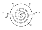
- FIG. 2 is a plan view of the orbiting scroll of the scroll compressor according to the first embodiment.
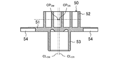
- FIG. 3 is a cross-sectional view of the orbiting scroll showing the III-III cross section of FIG.
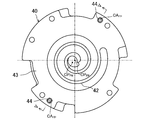
- FIG. 4 is a bottom view of the fixed scroll of the scroll compressor according to the first embodiment.
- FIG. 5 is a cross-sectional view of the fixed scroll showing the VV cross section of FIG. 4.
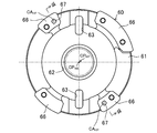
- FIG. 6 is a plan view of the housing of the scroll compressor according to the first embodiment.
- FIG. 7 is a cross-sectional view of the fixed scroll showing the VII-VII cross section of FIG. 6.
- FIG. 8 is an exploded cross-sectional view of the compression mechanism of the scroll compressor according to the first embodiment.
- FIG. 1 is a longitudinal sectional view of the scroll compressor according to the first embodiment.
- FIG. 2 is a plan view of the orbiting scroll of the scroll compressor according to the first embodiment.
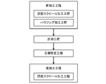
- FIG. 9 is a block diagram illustrating a main part of the method for manufacturing the scroll compressor according to the first embodiment.
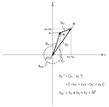
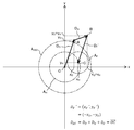
- FIG. 10 is a diagram illustrating the dimensional deviation of the scroll compressor according to the first embodiment in two-dimensional coordinates.
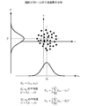
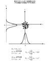
- FIG. 11 is a diagram showing the distribution of the dimensional deviation of the orbiting scroll of the scroll compressor according to the first embodiment in two-dimensional coordinates.
- FIG. 12 is a diagram showing the distribution of the dimensional deviation of the housing of the scroll compressor according to the first embodiment in two-dimensional coordinates.
- FIG. 13 is a diagram showing the distribution of the dimensional deviation of the fixed scroll of the scroll compressor according to the first embodiment in two-dimensional coordinates.
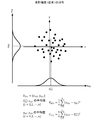
- FIG. 14 is a diagram showing the distribution of the total deviation of the scroll compressor according to the first embodiment in two-dimensional coordinates.
- FIG. 10 is a diagram illustrating the dimensional deviation of the scroll compressor according to the first embodiment in two-dimensional coordinates.
- FIG. 11 is a diagram showing the distribution of the dimensional deviation of the orbiting
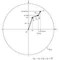
- FIG. 15 is a diagram showing the dimensional deviation of the orbiting scroll of the scroll compressor according to the second embodiment in two-dimensional coordinates.
- FIG. 16 is a diagram showing the dimensional deviation of the orbiting scroll of the scroll compressor according to the third embodiment in two-dimensional coordinates.
- FIG. 17 is a diagram showing the dimensional deviation of the orbiting scroll of the scroll compressor according to the fourth embodiment in two-dimensional coordinates.
- FIG. 18 is a diagram showing, in two-dimensional coordinates, the distribution of the dimensional deviation of the fixed scroll processed with the target value of the dimensional deviation as zero.
- FIG. 19 is a diagram showing the dimensional deviation of the orbiting scroll of the conventional scroll compressor in two-dimensional coordinates.
- FIG. 20 is a diagram showing the distribution of the total deviation of the conventional scroll compressor in two-dimensional coordinates.
- Embodiment 1 The scroll compressor (10) of Embodiment 1 is demonstrated.
- the scroll compressor (10) is a scroll fluid machine, and is connected to a refrigerant circuit (not shown) in which a refrigerant circulates and performs a refrigeration cycle, and compresses the refrigerant as a fluid.
- the scroll compressor (10) is a fully hermetic compressor in which a compression mechanism (30) and an electric motor (20) are accommodated in a casing (11) that is a hermetic container.
- the casing (11) is a cylindrical pressure vessel closed at both ends.
- the casing (11) is installed in a posture in which the axial direction is the vertical direction.
- a suction pipe (12) for introducing the refrigerant of the refrigerant circuit into the compression mechanism (30) is provided at the upper end of the casing (11).
- the casing (11) is provided with a discharge pipe (13) for leading the refrigerant in the casing (11) out of the casing (11).
- the electric motor (20) is disposed below the compression mechanism (30).
- the electric motor (20) and the compression mechanism (30) are connected by a drive shaft (25).
- the electric motor (20) includes a stator (21) and a rotor (22).
- the stator (21) of the electric motor (20) is fixed to the casing (11).
- the rotor (22) of the electric motor (20) is attached to the drive shaft (25).
- the drive shaft (25) includes a main shaft portion (26) and an eccentric shaft portion (27).
- the axis of the main shaft (26) coincides with the axis of the drive shaft (25).
- the rotor (22) of the electric motor (20) is attached to the main shaft portion (26).
- the main shaft portion (26) is supported at the upper portion of the rotor (22) by a bearing portion (64) of the housing (60) described later.
- the eccentric shaft portion (27) is formed in a relatively short shaft shape and protrudes from the upper end of the main shaft portion (26).
- the shaft center of the eccentric shaft portion (27) is substantially parallel to the shaft center of the main shaft portion (26) and is eccentric with respect to the shaft center of the main shaft portion (26).
- the compression mechanism (30) includes an orbiting scroll (50), a fixed scroll (40), a housing (60), and an Oldham coupling (32).
- the orbiting scroll (50) and the fixed scroll (40) form a compression chamber (31) that is a fluid chamber.
- the housing (60) is fixed to the casing (11).
- the fixed scroll (40) is disposed on the upper surface of the housing (60).
- the orbiting scroll (50) is disposed between the fixed scroll (40) and the housing (60).
- Oldham coupling (32) is arranged between orbiting scroll (50) and housing (60).
- the Oldham coupling (32) is engaged with a key groove (54) of the orbiting scroll (50), which will be described later, and a key groove (63) of the housing (60), which will be described later, and restricts the rotation of the orbiting scroll (50). .
- the orbiting scroll (50) includes an orbiting side end plate portion (51), an orbiting side wrap (52), and a boss portion (53).
- the turning side end plate part (51) is formed in a substantially circular flat plate shape.
- the turning side wrap (52) is formed in a spiral wall shape that draws an involute curve, and protrudes from the front surface (upper surface in FIG. 3) of the turning side end plate portion (51).
- the boss portion (53) is formed in a cylindrical shape protruding from the back surface (the lower surface in FIG. 3) of the turning side end plate portion (51), and is arranged at the center of the turning side end plate portion (51).
- the boss part (53) constitutes a journal bearing.
- the eccentric shaft portion (27) of the drive shaft (25) is inserted into the boss portion (53) (see FIG. 1).
- a keyway (54) is formed in the turning side end plate portion (51) of the turning scroll (50).
- the key groove (54) is a concave groove that opens on the back surface of the turning-side end plate.
- the key grooves (54) are arranged one by one at positions facing each other across the boss portion (53).
- the key of the Oldham coupling (32) is fitted into the key groove (54).
- Straight CL OB is the central axis CL OB of the boss portion (53), the point CP OB is a point on the center axis CL OB of the boss (53).
- the point CP OW is the center of the turning side wrap (52), and the straight line CL OW is the central axis CL OW of the turning side wrap (52).
- the center of the turning wrap (52) is the center of the foundation circle of the involute curve that defines the shape of the turning wrap (52).
- the points CP OB and CP OW are points on one plane orthogonal to the central axis CL OB of the boss portion (53).
- the central axis CL OW of the turning side wrap (52) is a straight line that passes through the point CP OW and is parallel to the central axis CL OB of the boss portion (53).
- the dimensional deviation D O of the orbiting scroll (50) is the deviation of the central axis CL OB of the boss portion (53) from the central axis CL OW of the orbiting side wrap (52).
- the dimensional deviation D O is a vector having a point CP OW as a start point and a point CP OB as an end point. 2 and 3, the dimensional deviation D O of the orbiting scroll (50) is exaggerated.
- the size deviation D O of the orbiting scroll (50) is about several tens of ⁇ m at the maximum.
- the fixed scroll (40) includes a fixed side end plate portion (41), a fixed side wrap (42), and an outer peripheral wall portion (43).
- the fixed-side end plate portion (41) is a relatively thick flat plate-like portion located above the fixed scroll (40).
- the stationary side wrap (42) is formed in a spiral wall shape that draws an involute curve, and projects from the front surface (lower surface in FIG. 5) of the stationary side end plate portion (41).
- the outer peripheral wall portion (43) is formed so as to surround the outer peripheral side of the fixed side wrap (42), and protrudes from the front surface of the fixed side end plate portion (41).
- the protruding end surface (lower end surface in FIG. 5) of the outer peripheral wall portion (43) is a substantially flat surface. Further, the projecting end surface of the outer peripheral wall portion (43) is located on the same plane as the projecting end surface (lower end surface in FIG. 5) of the fixed side wrap (42).
- Each positioning hole (44) is a positioning structure for determining a fixed position of the fixed scroll (40) with respect to the housing (60).
- Each positioning hole (44) is a hole with a circular cross section that opens to the protruding end face of the outer peripheral wall (43).
- Each positioning hole (44) has a central axis substantially parallel to each other, and each central axis is substantially orthogonal to the protruding end surface of the outer peripheral wall (43).
- Each positioning hole (44) is disposed near the outer peripheral edge of the outer peripheral wall (43).
- two positioning holes (44) are arrange
- the straight line CL FP is the fixed side central axis CL FP
- the point CP FP is a point on the fixed side central axis CL FP
- Stationary central shaft CL FP is located on one plane including the central axis CA FP of two positioning holes (44), the distance is equal to the straight line from the central axis CA FP of each of the positioning holes (44).
- the fixed-side central axis CL FP is located at the same distance and the shortest distance from the central axis CA FP of each positioning hole (44).
- the point CP FW is the center of the fixed side wrap (42), and the straight line CL FW is the central axis CL FW of the fixed side wrap (42).
- the center of the fixed side wrap (42) is the center of the base circle of the involute curve that defines the shape of the fixed side wrap (42).
- the point CP FP and the point CP FW are points on one plane orthogonal to the fixed-side central axis CL FP .
- the central axis CL FW of the fixed side wrap (42) is a straight line that passes through the point CP FW and is parallel to the fixed side central axis CL FP .
- the dimension deviation DF of the fixed scroll (40) is a deviation of the center axis CL FW of the fixed side wrap (42) from the fixed side center axis CL FP .
- This dimensional deviation D F is a vector having a point CP FP as a start point and a point CP FW as an end point. 4 and 5, the dimensional deviation DF of the fixed scroll (40) is exaggerated.
- the size deviation DF of the fixed scroll (40) is about several tens of ⁇ m at the maximum.
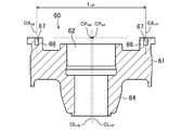
- the housing (60) includes a main body portion (61), a bearing portion (64), and a holding projection (66).
- the main body (61) is formed in a thick disk shape.
- a crank chamber (62) is formed at the center of the main body (61).
- the crank chamber (62) is a cylindrical recess that opens to the front surface (upper surface in FIG. 7) of the main body (61).
- a keyway (63) is formed in the main body (61).
- the key groove (63) is a concave groove that opens on the front surface of the main body (61).
- the key grooves (63) are arranged one by one at positions facing each other across the crank chamber (62).
- the key of the Oldham coupling (32) is fitted into the key groove (63).
- the bearing portion (64) is formed in a cylindrical shape protruding from the back surface (the lower surface in FIG. 7) of the main body portion (61), and is disposed at the center of the main body portion (61).
- the bearing portion (64) constitutes a journal bearing.
- a bearing metal (65) is disposed inside the bearing portion (64) (see FIG. 1).
- the main shaft portion (26) of the drive shaft (25) is inserted through the bearing portion (64).
- the housing (60) has four holding protrusions (66). Each holding projection (66) protrudes from the front surface of the main body (61). Each holding projection (66) is formed in a curved shape extending along the outer peripheral edge of the main body (61). The protruding end surface (upper surface in FIG. 7) of each holding projection (66) is a substantially flat surface. Further, the projecting end surfaces of the holding projections (66) are located on substantially the same plane.
- Each positioning hole (67) is a positioning structure for determining a fixed position of the fixed scroll (40) with respect to the housing (60).
- Each positioning hole (67) is a hole with a circular cross section that opens to the protruding end face of the holding projection (66).
- Each positioning hole (67) has a central axis substantially parallel to each other, and each central axis is substantially orthogonal to the protruding end surface of the holding projection (66).
- One of the two positioning holes (67) is arranged on the opposite side of the crank chamber (62) with respect to the other. “Fitting” between each positioning hole (67) and a positioning pin (35) to be described later is selected so that the fixed position of the fixed scroll (40) with respect to the housing (60) can be determined with a desired accuracy.
- the straight line CL HB is the central axis CL HB of the bearing portion (64), and the point CP HB is a point on the central axis CL HB of the bearing portion (64).
- the straight line CL HP is the housing side central axis CL HP , and the point CP HP is a point on the housing side central axis CL HP .
- Housing-side center axis CL HP is located on one plane including the central axis CA HP two positioning holes (67), the distance is equal to the straight line from the central axis CA HP of each of the positioning holes (67).
- the housing side central axis CL HP is located at the shortest distance from the central axis CA HP of each positioning hole (67).
- the dimensional deviation DH of the housing (60) is a deviation of the housing side central axis CL HP with respect to the central axis CL HB of the bearing portion (64).
- the dimensional deviation DH is a vector having a point CP HB as a start point and a point CP HP as an end point. 6 and 7, the dimensional deviation DH of the housing (60) is exaggerated.
- the size of the dimensional deviation DH of the housing (60) is about several tens of ⁇ m at the maximum.
- the fixed scroll (40) is disposed above the housing (60), and the orbiting scroll (50) is disposed between the fixed scroll (40) and the housing (60).
- an Oldham coupling (32) is disposed between the orbiting scroll (50) and the housing (60).
- the fixed scroll (40) and the housing (60) are combined in such a posture that the positioning pins (35) are fitted in the positioning holes (44, 67). That is, the corresponding positioning pins (35) are fitted into the positioning holes (44) of the fixed scroll (40) facing each other and the positioning holes (67) of the housing (60) one by one. Therefore, in a state where the fixed scroll (40) and the housing (60) are combined, the central axis CAFP of each positioning hole (44) of the fixed scroll (40) and each positioning hole (67) of the housing (60) The central axes CA HP substantially coincide with each other.
- the fixed scroll (40) is fixed to the housing (60) by a plurality of bolts (not shown). When this bolt is tightened, the protruding end surface of the outer peripheral wall portion (43) of the fixed scroll (40) comes into close contact with the protruding end surface of the holding protruding portion (66) of the housing (60). Then, the fixed scroll (40), relative to the housing (60), the fixed side center axis CL FP is fixed in a posture substantially coincident with the housing-side center axis CL HP.
- a turning scroll process In the process of processing the components of the compression mechanism (30), a turning scroll process, a housing process, a fixed scroll process, a measurement process, and a target setting process are performed.
- the orbiting scroll processing step and the housing processing step are pre-processing steps
- the fixed scroll processing step is a post-processing step.
- the fixed scroll (40) processed in the post-processing step is the first component
- the orbiting scroll (50) and the housing (60) processed in the pre-processing step are provided. This is the second part.
- the orbiting scroll processing step and the housing processing step which are the pre-processing steps, are performed before the measurement step and the target setting step.
- One of the orbiting scroll processing step and the housing processing step, which are pre-processing steps, may be performed after the other, or both may be performed simultaneously in parallel.
- the fixed scroll processing step which is a post-processing step, is performed after the measurement step and the target setting step.
- orbiting scroll machining process cutting is performed on the surface of the orbiting side wrap (52), the front surface of the orbiting side end plate part (51), the inner peripheral surface of the boss part (53), and the surface of the keyway (54). (See FIG. 2 and FIG. 3). That is, in the orbiting scroll machining step, the orbiting side wrap (52) and the boss portion (53) are machined. In this orbiting scroll machining process, the machining conditions of the orbiting side wrap (52) and the boss part (53) are such that the center axis CL OW of the orbiting side wrap (52) and the center axis CL OB of the boss part (53) coincide. (That is, a condition in which the target value of the dimensional deviation D O of the orbiting scroll (50) is zero).
- ⁇ Housing processing process> the protrusion end surface of the holding protrusion (66), the peripheral surface of the crank chamber (62), the inner peripheral surface of the bearing (64), and the surface of the key groove (63) Cutting is performed (see FIGS. 6 and 7). Further, in the housing processing step, processing for forming a positioning hole (67) in the holding projection (66) is performed. That is, in the housing processing step, the bearing portion (64) and the positioning hole (67) are processed.
- the processing conditions of the bearing portion (64) and the positioning hole (67) are the conditions that aim to make the center axis CL HB of the bearing portion (64) coincide with the housing side center axis CL HP (ie, , A condition in which the target value of the dimensional deviation DH of the housing (60) is zero).
- ⁇ Measurement process> In the measurement process, the dimensions of each of the orbiting scroll (50) processed in the orbiting scroll processing process and the housing (60) processed in the housing processing process are measured. Then, in the measuring step, the dimensional deviations D O of the orbiting scroll (50), and dimensional deviations D H of the housing (60) is calculated.
- the position of the center point CP OW of the orbiting side wrap (52), a point on the center axis CL OB of the boss (53) The position of the CP OB is calculated (see FIGS. 2 and 3).
- the dimension deviation D O of the orbiting scroll (50) is a vector having the point CP OW as the start point and the point CP OB as the end point.
- a vector D O that is a dimensional deviation of the orbiting scroll (50) is specified based on the calculated positions of the point CP OW and the point CP OB .
- the position of the point CP HB on the central axis CL HB of the bearing portion (64) and the point CP HP on the housing side central axis CL HP The position is calculated (see FIGS. 6 and 7).
- the dimensional deviation DH of the housing (60) is a vector having the point CP HB as the start point and the point CP HP as the end point.
- a vector DH that is a dimensional deviation of the housing (60) is specified based on the calculated positions of the point CP HB and the point CP HP .
- a target value of the dimensional deviation DF of the fixed scroll (40) processed in the fixed scroll processing step which is a post-processing step is set.
- the dimension deviation D O is set so as to cancel out the dimension deviation D H of the housing (60).
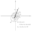
- FIG. 10 shows two-dimensional coordinates with the origin O as the center point CPOW of the turning wrap (52).
- the dimensional deviation of the housing (60) obtained in the measuring process is set as a vector D.
- H (x H , y H ).
- Point A is a point CP OB on the central axis CL OB of the boss portion (53) and a point CP HB on the central axis CL HB of the bearing portion (64).
- Point B is a point CP HP on the housing-side central axis CL HP .
- the relative positions of the fixed scroll (40) and the housing (60) are set by positioning pins (35) that fit into the positioning holes (44, 67).
- the point CP FP on the fixed-side central axis CL FP has the same distance from the central axis CA FP of each positioning hole (44).
- the point CP HP on the housing side central axis CL HP is equal in distance from the central axis CA HP of each positioning hole (67). For this reason, the point CP FP of the fixed scroll (40) coincides with the point CP HP of the housing (60). Therefore, in FIG. 10, the start point of the vector DF , which is the dimensional deviation of the fixed scroll (40), is the point B.
- ⁇ Fixed scroll processing process> cutting is performed on the surface of the fixed side wrap (42), the front surface of the fixed side end plate portion (41), and the front surface of the outer peripheral wall portion (43) (FIGS. 4 and 5). See). Further, in the fixed scroll processing step, processing for forming the positioning hole (44) in the outer peripheral wall portion (43) is performed. That is, in the fixed scroll processing step, the fixed side wrap (42) and the positioning hole (44) are processed. In this fixed scroll processing step, the fixed side wrap (42) and the positioning hole (44) are processed under the processing conditions such that the vector DF, which is the dimensional deviation of the fixed scroll (40), becomes the target vector DF '. Is called.
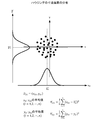
- FIG. 11 shows the distribution of the dimensional deviation (vector D O ) for several tens of orbiting scrolls (50) in two-dimensional coordinates.
- the origin of the two-dimensional coordinates is a point CP OW (that is, the starting point of the vector D O ) on the central axis CL OW of the turning side wrap (52).
- the point on the two-dimensional coordinates is a point CP OB (that is, an end point of the vector D O ) on the central axis CL OB of the boss part (53).
- the x-direction component and the y-direction component of the dimensional deviation (vector D O ) of the orbiting scroll (50) are normal distributions as shown in FIG.
- the variance of the x direction component is V Ox and the variance of the y direction component is V Oy .
- the orbiting side wrap (52) is processed from the front side of the orbiting side end plate part (51), and the boss part (53) is processed from the back side of the orbiting side end plate part (51). .
- the dimension deviation (vector D O ) of the orbiting scroll (50) is relatively large in the variance V Ox of the x-direction component and the variance V Oy of the y-direction component.
- the bearing portion (64) and the positioning hole (67) are processed under a processing condition aimed at matching the central axis CL HB of the bearing portion (64) with the central axis CL HP of the housing side. Is processed.
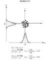
- FIG. 12 shows the distribution of the dimensional deviation (vector D H ) for several tens of housings (60) in two-dimensional coordinates.
- the origin of the two-dimensional coordinates is a point CP HB (that is, the starting point of the vector DH ) on the central axis CL HB of the bearing portion (64).
- the point on the two-dimensional coordinates a point on the housing side the center axis CL HP CP HP (i.e., the end point of the vector D H).
- the probability distribution of the x-direction component and the y-direction component of the dimensional deviation (vector D H ) of the housing (60) is a normal distribution as shown in FIG.
- the variance of the x-direction component is V Hx
- the variance of the y-direction component is V Hy .
- the bearing (64) of the housing (60) forms a hole penetrating the main body (61). Therefore, in the housing processing step, the position of the center axis CL HB is determined by measuring the bearing portion (64) from the front side of the main body (61) while keeping the posture of the workpiece constant, and the specified center axis CL The processing position of the positioning hole (67) can be determined based on the position of HB . For this reason, the machining error that occurs in the housing machining process is usually smaller than the machining error that occurs in the orbiting scroll machining process.
- the variance V Hx of the x-direction component and the variance V Hy of the y-direction component of the dimensional deviation (vector D H ) of the housing (60) are respectively the dimensional deviation (vector D O ) of the orbiting scroll (50). It becomes smaller than the dispersion V Ox and the dispersion V Oy .
- the fixed side wrap (42) and the positioning hole (44) of the fixed side wrap (42) are processed under a processing condition aimed at matching the dimensional deviation of the fixed scroll (40) with the target vector DF ′. Processing is performed.
- Target vector D F ' is set so as to offset the dimensional deviations D H of dimensional deviations D O and the housing of the orbiting scroll (50) (60). Accordingly, the target vector D F ′ includes a machining error that occurs in the orbiting scroll machining process and a machining error that occurs in the housing machining process. Furthermore, a processing error also occurs in the fixed scroll processing step. For this reason, the dimensional deviation (vector D F ) of the fixed scroll (40) processed in the fixed scroll processing step does not normally coincide with the target vector D F ′.
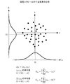
- FIG. 13 shows the distribution of each dimensional deviation (vector D F ) in two-dimensional coordinates for several tens of fixed scrolls (40) processed by the fixed scroll processing step of the present embodiment.
- the origin of the two-dimensional coordinates is a point CP FP (that is, the start point of the vector DF ) on the fixed-side central axis CL FP .
- the point on the two-dimensional coordinates is a point CP FW (that is, the end point of the vector DF ) on the central axis CL FW of the fixed side wrap (42).
- the probability distribution of the dimensional deviation (vector D F ) of the fixed scroll (40) and the y-direction component are normal distributions as shown in FIG.
- the variance of the x-direction component is V Fx
- the variance of the y-direction component is V Fy .
- the dimension deviation (vector D F ) of the fixed scroll (40) processed in the fixed scroll processing step includes processing errors in the orbiting scroll processing step and the housing processing step included in the target vector D F ′, and the fixed scroll processing step. Processing error.
- the variance V Fx of the x-direction component of the dimensional deviation (vector D F ) of the fixed scroll (40) is equal to the variance V Ox of the x-direction component of the dimensional deviation (vector D O ) of the orbiting scroll (50).
- the variance V Fx is equal to or greater than the sum of the variance V Ox and the variance V Hx (V Fx ⁇ V Ox + V Hx ).
- the variance V Fy of the y direction component of the dimensional deviation (vector D F ) of the fixed scroll (40) is the variance V Oy of the y direction component of the dimensional deviation (vector D O ) of the orbiting scroll (50) and the housing ( 60) and the variance V Hy of the y-direction component of the dimensional deviation (vector D H ).
- the variance V Fy is equal to or greater than the sum of the variance V Oy and the variance V Hy (V Fy ⁇ V Oy + V Hy ).
- the fixed scroll (40) processed in the fixed scroll processing step of the present embodiment has a variance V Fx of the x direction component and a variance V Fy of the y direction component of the dimensional deviation (vector D F ) of the fixed scroll (40).
- V Fx of the x direction component
- V Fy of the y direction component of the dimensional deviation (vector D F ) of the fixed scroll (40).
- Distance L FP positioning hole (44) to each other is the distance of the central axis CA FP of the respective positioning hole (44) (see Figure 5).
- ⁇ Machining error in fixed scroll machining process> A processing error that occurs in the fixed scroll processing step of the present embodiment will be described.
- the machining error that occurs in the fixed scroll machining process of the present embodiment is substantially the same as the machining error that occurs in a general fixed scroll machining process.
- FIG. 18 shows the distribution of dimensional deviations (vector D F ) in two-dimensional coordinates for several tens of fixed scrolls (40) processed in a general fixed scroll processing step.
- the two-dimensional coordinates in FIG. 18 are the same as the two-dimensional coordinates shown in FIG.
- both the fixed side wrap (42) and the positioning hole (44) are processed from the projecting end surface side of the outer peripheral wall portion (43). Done. For this reason, the machining error that occurs in the fixed scroll machining process is usually smaller than the machining error that occurs in the orbiting scroll machining process.
- the dimensional deviation (vector D F ) of the fixed scroll (40) is normally ,
- the variance V Fx of the x-direction component and the variance V Fy of the y-direction component are smaller than the variance V Ox and the variance V Oy of the dimensional deviation (vector D O ) of the orbiting scroll (50), respectively.
- Total deviation D AS is the sum of the dimensional deviations (vector D F) of the dimensional deviations (vector D H) and the fixed scroll (40) of the dimensional deviations (vector D O) and the housing (60) of the orbiting scroll (50), It is the sum of the vector D O , the vector D H and the vector D F.
- the end point of the combined vector D AS which is the sum of the vector D O , the vector D H, and the vector D F , is the end point C of the vector D F starting from the point B (see FIG. 10).
- the processing error that occurs in the fixed scroll processing step of the present embodiment is the case where the fixed scroll (40) is processed under the processing conditions aimed at making the dimensional deviation DF of the fixed scroll (40) zero. This is substantially the same as the machining error. Therefore, the end point C of the combined vector D AS that is the sum of the vector D O , the vector D H, and the vector D F is located in the area A AS1 in FIG.
- the area A AS1 is schematically a perfect circle centered on the origin O.
- the area A AS1 is a slightly distorted circle, and the center of the area A AS1 is slightly shifted from the origin O.
- dimensional deviations of dimensional deviations of the orbiting scroll (50) (Vector D O) and the housing (60) (Vector D H) is offset by dimensional deviations of the fixed scroll (40) (Vector D F) . Therefore, practically, only the machining error generated in the fixed scroll machining process, which is a post-machining process, causes the total deviation (vector D AS ) in the present embodiment.
- FIG. 14 shows the distribution of the total deviation (vector D AS ) in two-dimensional coordinates for dozens of orbiting scrolls (50), fixed scrolls (40), and housings (60).
- the origin of the two-dimensional coordinates is a point CP OW (that is, the start point of the vector D AS ) on the center axis CL OW of the turning side wrap (52).
- the point on the two-dimensional coordinates is a point CP FW (end point of the vector D AS ) on the central axis CL FW of the fixed wrap (42).
- the x-direction component and the y-direction component of the total deviation (vector D AS ) are normal distributions as shown in FIG. In the total deviation (vector D AS ), the variance of the x-direction component is V ASx and the variance of the y-direction component is V ASy .
- the cause of the total deviation (vector D AS ) in the present embodiment is substantially only the processing error generated in the fixed scroll processing step which is the post-processing step.
- the variance V ASx of the x-direction component and the variance V ASy of the y-direction component of the total deviation (vector D AS ) shown in FIG. 14 are respectively the dimensional deviation (vector D F ) of the fixed scroll (40) shown in FIG. ) substantially coincides with the variance V Fy of variance V Fx and y-direction component in the x direction component of.
- the measured value of the obtained dimension includes an error of the measuring instrument.
- the variance V ASx and variance V ASy of the total deviation (vector D AS ) shown in FIG. 14 are the variance V Fx and variance V Fy of the dimensional deviation (vector D F ) of the fixed scroll (40) shown in FIG. Not exactly the same.
- the dispersion of the dimensional deviation D F is different from the dispersion of the dimensional deviation D O of the orbiting scroll (50) and the housing (60 ) Dispersion of the dimensional deviation DH . Therefore, the variance V ASx of the x-direction component and the variance V ASy of the y-direction component of the total deviation (vector D AS ) shown in FIG. 14 are respectively the dimensional deviation (vector D F ) of the fixed scroll (40) shown in FIG. Is smaller than the variance V Fx of the x-direction component and the variance V Fy of the y-direction component.
- the manufacturing method of the present embodiment supports the orbiting scroll (50) in which the orbiting side wrap (52) and the boss part (53) are formed, and the rotating shaft connected to the boss part (53) of the orbiting scroll (50).
- the manufacturing method of the present embodiment includes a turning scroll processing step for processing the turning side wrap (52) and the boss portion (53) of the turning scroll (50) that is a workpiece, and a fixed scroll (40) that is a workpiece.
- the orbiting scroll processing step and the housing processing step are pre-processing steps
- the fixed scroll processing step is a post-processing step.
- the deviation of the central axis CL OB of the boss portion (53) with respect to the central axis CL OW of the orbiting side wrap (52) is defined as the dimensional deviation D O of the orbiting scroll (50).
- the straight line located at the shortest equidistant distance from each positioning hole (67) is the housing side central axis CL HP, and the deviation of the housing side central axis CL HP from the central axis CL HB of the bearing portion (64) is the housing (60).
- a straight line is positioned equidistant the shortest from the positioning hole (44) of the fixed scroll (40) and the fixed side center axis CL FP, fixed scroll wrap relative to the fixed center axis CL FP (42) the center axis CL of the FW deviation and dimensional deviations D F of the fixed scroll (40), dimensional deviations D of dimensional deviations D O and the housing (60) of the dimensional deviations D H and the fixed scroll of the orbiting scroll (50) (40) of F Total and total deviation D AS.
- the orbiting scroll processing step and the housing processing step are pre-processing steps
- the fixed scroll processing step is a post-processing step.
- the manufacturing method of this embodiment was measured in the measurement process which measures the dimensional deviation of the turning scroll (50) and the housing (60) processed in the pre-processing process, and the measurement process after the pre-processing process is completed.
- the fixed scroll (40) processed in the post-processing step so that the dimensional deviation of the orbiting scroll (50) and the housing (60) is offset by the dimensional deviation of the fixed scroll (40) processed in the post-processing step.
- a target setting step for setting a target value of the dimensional deviation.
- the fixed scroll (40) is set so that the dimensional deviation of the fixed scroll (40) becomes the target value set in the target setting step. Processing.
- the orbiting scroll (50), the fixed scroll (40), and the housing (60) are processed with the goal of making each dimensional deviation zero. It was done on condition.
- the dimensional deviations of the orbiting scroll (50), fixed scroll (40) and housing (60) may or may not cancel each other. .
- FIG. 19 shows the dimension deviation (vector D O ) of the orbiting scroll (50), the dimension deviation (vector D F ) of the fixed scroll (40) and the housing (60) in the scroll compressor (10) manufactured by the conventional manufacturing method.
- the end point C of the combined vector D AS which is the sum of the vector D O , the vector D H, and the vector D F , is located in the area A AS5 in FIG.
- FIG. 20 shows the distribution of the total deviation (combined vector D AS ) in the scroll compressor (10) manufactured by the conventional manufacturing method in the same two-dimensional coordinates as in FIG.
- the target setting step dimensional deviations D O of the orbiting scroll (50) and the dimensional deviations D H of the housing (60), the dimensional deviations D F of the fixed scroll (40)
- the target value of the dimensional deviation DF of the fixed scroll (40) is set.
- the “dimensional deviation (vector D F ) of the fixed scroll (40)” is “the target value set in the target setting step (target vector D F ′)”. Then, the fixed scroll (40) is processed.
- the size of the area A AS1 where the end point C of the vector D AS (total deviation) can exist can be significantly reduced compared to the area A AS5 shown in FIG. 14 and 20, it is clear that according to the manufacturing method of the present embodiment, the variances V ASx and V AS for the x direction component and the y direction component of the total deviation (vector D AS ), respectively. Asy can be greatly reduced as compared with the prior art .
- the processing of the orbiting scroll (50), the housing (60), and the fixed scroll (40) is performed with the same level of processing accuracy as before, and the variance of the total deviation D AS is reduced. be able to. Therefore, the design values of the dimensions of the orbiting scroll (50), the housing (60), and the fixed scroll (40) can be made closer to the ideal dimensions when the machining error is zero. As a result, the gap between the turning side wrap (52) and the fixed side wrap (42) in the assembled state can be reduced, and the amount of fluid leaking from the compression chamber (31) through this gap can be reduced. Therefore, according to the present embodiment, the efficiency of the scroll compressor (10) can be improved while suppressing an increase in the manufacturing cost of the scroll compressor (10).
- the dispersion of the dimensional deviation D F of the fixed scroll (40) is different from the dispersion of the dimensional deviation D O of the orbiting scroll (50) and the housing (60). ) encompassing the dispersion and dimension deviation D H of, and variance of the total deviation D aS is smaller than the variance of the dimensional deviations D F of the fixed scroll (40).
- the variance of the total deviation cannot be made smaller than the variance of the dimensional deviation of the fixed scroll (40).
- the total deviation D it is possible to make the variance of AS smaller than the variance of the dimensional deviation DF of the fixed scroll (40). Therefore, according to the present embodiment, it becomes possible to reduce the variance of the total deviation D AS without increasing the processing accuracy of the orbiting scroll (50), the housing (60), and the fixed scroll (40) as compared with the prior art.
- the efficiency of the compressor (10) can be improved.
- the scroll compressor (10) manufactured by the manufacturing method of the present embodiment has a fixed scroll (40) such that the variance of the total deviation D AS is smaller than the variance of the dimensional deviation D F of the fixed scroll (40). ) Of the dimensional deviation D F is larger than the variance of the interval L FP between the plurality of positioning holes (44) formed in the fixed scroll (40).
- the dispersion of the dimensional deviation of the orbiting scroll (50), the housing (60), and the fixed scroll (40) is approximately 30 for each of the orbiting scroll (50), the housing (60), and the fixed scroll (40). This can be calculated by measuring
- Embodiment 2 The scroll compressor (10) of Embodiment 2 and its manufacturing method will be described. Here, the difference from Embodiment 1 is demonstrated about each of the scroll compressor (10) of this embodiment, and its manufacturing method.
- the orbiting scroll processing step and the fixed scroll processing step are pre-processing steps
- the housing processing step is a post-processing step.
- One of the orbiting scroll processing step and the fixed scroll processing step, which are pre-processing steps, may be performed after the other, or both may be performed simultaneously.
- the housing (60) processed in the post-processing step is the first part
- the orbiting scroll (50) and the fixed scroll (40) processed in the pre-processing step are provided. This is the second part.
- the orbiting scroll machining process of the present embodiment is the same as the orbiting scroll machining process of the first embodiment.
- the orbiting side wrap (52) center axis CL OW and the boss portion (53) processing conditions targeted to match the central axis CL OB of i.e., the orbiting scroll ( in the target value of the dimensional deviations D O 50) was zero processing conditions
- the processing is performed of the orbiting side wrap (52) and the boss portion (53).
- the fixed scroll processing step of the present embodiment is different from the fixed scroll processing step of the first embodiment in processing conditions.
- the processing conditions that is, the dimensional deviation D of the fixed scroll (40)
- the fixed side wrap (42) and the positioning hole (44) are processed under the processing conditions in which the target value of F is zero.
- ⁇ Measurement process> dimensions are measured for each of the orbiting scroll (50) processed in the orbiting scroll processing process and the fixed scroll (40) processed in the fixed scroll processing process.
- the dimensional deviation D O of the orbiting scroll (50) and the dimensional deviation DF of the fixed scroll (40) are calculated.
- Calculating a dimensional deviations D O of the orbiting scroll (50) is the same as Embodiment 1. That is, in the measurement process, the position of the center point CP OW of the turning side wrap (52) and the position of the point CP OB on the center axis CL OB of the boss portion (53) are calculated, and turning is performed based on these positions. A vector D O which is a dimensional deviation of the scroll (50) is specified.
- the position of the center point CP FW of the fixed side wrap (42) and the position of the point CP FP on the fixed side center axis CL FP are calculated based on the measured value of the dimension of the fixed scroll (40).
- the dimension deviation DF of the fixed scroll (40) is a vector having the point CP FP as the start point and the point CP FW as the end point.
- a vector DF that is a dimensional deviation of the fixed scroll (40) is specified based on the calculated positions of the point CP FW and the point CP FP .
- ⁇ Target setting process> a target value of the dimensional deviation DH of the housing (60) to be processed in the housing processing step which is a post-processing step is set.
- the target setting process of this embodiment will be described with reference to FIG.
- FIG. 15 is a diagram corresponding to FIG. 10 relating to the first embodiment.
- FIG. 15 shows two-dimensional coordinates having the origin O as the center point CP OW of the turning side wrap (52).
- D F (x F , y F ).
- the housing (60) the target vector D H ' which is a target value of the dimensional deviations D H of dimensional deviations D O and the fixed scroll of the calculated orbiting scroll in the measurement step (50) ( 40) is set so as to cancel out the dimensional deviation D F in FIG.
- the housing processing step of this embodiment differs from the housing processing step of Embodiment 1 in processing conditions.
- the bearing portion (64) and the positioning hole (67) are processed under processing conditions such that the vector DH, which is the dimensional deviation of the housing (60), becomes the target vector DH ′. Is called.
- the dimensional deviations of the orbiting scroll (50), the fixed scroll (40), and the housing (60) and the total deviation that is the sum of them are described. To do.
- the dimensional deviation of the orbiting scroll (50) is the same as that of the first embodiment, the description thereof is omitted.
- the fixed scroll (40) is processed under the processing conditions aimed at making the dimension deviation DF of the fixed scroll (40) zero. Therefore, the dimensional deviation of the fixed scroll (40) processed in the fixed scroll processing step of the present embodiment is the same as the dimensional deviation of the fixed scroll (40) processed in the general fixed scroll processing step described in the first embodiment. Is the same as That is, the variance V Fx of the x-direction component and the variance V Fy of the y-direction component of the dimensional deviation (vector D F ) of the fixed scroll (40) of the present embodiment are respectively the dimensional deviation (vector D) of the orbiting scroll (50). O 2 ) smaller than the dispersion V Ox and the dispersion V Oy .
- the target vector D H ′ is set so as to cancel out the dimension deviation D O of the orbiting scroll (50) and the dimension deviation D F of the fixed scroll (40). Therefore, the target vector D H ′ includes a machining error that occurs in the orbiting scroll machining process and a machining error that occurs in the fixed scroll machining process. Furthermore, a processing error also occurs in the housing processing step. For this reason, the dimensional deviation (vector D H ) of the housing (60) processed in the housing processing step does not normally coincide with the target vector D H ′.
- the dimensional deviation (vector D H ) of the housing (60) processed in the housing processing step includes processing errors in the orbiting scroll processing step and the housing (60) fixed scroll processing step included in the target vector D H ′, and the fixed scroll. And machining errors in the machining process.
- the variance V Hx of the x direction component of the dimensional deviation (vector D H ) of the housing (60) is the variance V Ox of the x direction component of the dimensional deviation (vector D O ) of the orbiting scroll (50) and the fixed scroll.
- the variance V Hx is equal to or greater than the sum of the variance V Ox and the variance V Fx (V Hx ⁇ V Ox + V Fx ).
- the variance V Hy of the y direction component of the dimensional deviation (vector D H ) of the housing (60) is equal to the variance V Oy of the y direction component of the dimensional deviation (vector D O ) of the orbiting scroll (50) and the fixed scroll ( 40) and the variance V Fy of the y-direction component of the dimensional deviation (vector D F ).
- the variance V Hy is equal to or greater than the sum of the variance V Oy and the variance V Fy (V Hy ⁇ V Oy + V Fy ).
- the housing (60) processed in the housing processing step of the present embodiment has an x-direction component variance V Hx and a y-direction component variance V Hy of the dimensional deviation (vector D H ) of the housing (60).
- the distance L HP between the two positioning holes (67) is larger than the dispersion of the HP .
- the distance L HP between the positioning holes (67) is the distance between the central axes CA HP of the positioning holes (67) (see FIG. 7).
- Total deviation D AS is the sum of the dimensional deviations (vector D F) of the dimensional deviations (vector D H) and the fixed scroll (40) of the dimensional deviations (vector D O) and the housing (60) of the orbiting scroll (50), It is the sum of the vector D O , the vector D H and the vector D F.
- the end point of the combined vector D AS which is the sum of the vector D O , the vector D H, and the vector D F , is the end point C of the vector D F starting from the point B (see FIG. 15).
- the total deviation is zero (zero vector).
- processing errors also occur in the housing processing step, which is a post-processing step. For this reason, in most cases, the dimensional deviation (vector D H ) of the housing (60) is different from the target vector D H ′, and therefore the total deviation is not zero.
- the processing error that occurs in the housing processing step of this embodiment is substantially the same as the processing error that occurs when the housing (60) is processed under processing conditions that aim to make the dimensional deviation DH of the housing (60) zero.
- End point B of the vector D H is the dimension deviation of the housing (60) is located within the area A H of FIG. 15. Therefore, the end point C of the combined vector D AS that is the sum of the vector D O , the vector D H, and the vector D F is located in the area A AS2 in FIG.
- the area A AS2 is schematically a perfect circle centered on the origin O.
- the actual area A AS2 is a slightly distorted circle, and the center of the actual area A AS2 is slightly shifted from the origin O.
- the housing (60) processed in the housing processing step of this embodiment has a dispersion of the dimensional deviation D H, a dispersion of the dimensional deviation D O of the orbiting scroll (50), and a fixed scroll (40).
- dispersion of the dimensional deviation D F of Accordingly, the variance V ASx of the x-direction component and the variance V ASy of the y-direction component of the total deviation (vector D AS ) are the variance V Hx of the x-direction component of the dimensional deviation (vector D H ) of the housing (60), respectively. It is smaller than the variance V Hy of the y-direction component.
- the orbiting scroll processing step and the fixed scroll processing step are pre-processing steps
- the housing processing step is a post-processing step.
- the manufacturing method of this embodiment is measured in the measurement process which measures the dimensional deviation of the turning scroll (50) and fixed scroll (40) processed in the pre-processing process, and the measurement process after the end of the pre-processing process.
- the housing (60) processed in the post-processing step so that the dimensional deviation of the orbiting scroll (50) and the fixed scroll (40) is offset by the dimensional deviation of the housing (60) processed in the post-processing step.
- a target setting step for setting a target value of the dimensional deviation.
- the housing (60) is processed so that the dimensional deviation of the housing (60) becomes the target value set in the target setting step.
- the manufacturing method of the present embodiment as with the manufacturing method of the first embodiment, while processing the orbiting scroll (50), the housing (60), and the fixed scroll (40) with the same processing accuracy as before, The variance of the total deviation D AS can be reduced. Therefore, according to the present embodiment, as in the first embodiment, the efficiency of the scroll compressor (10) can be improved while suppressing an increase in the manufacturing cost of the scroll compressor (10).
- the dispersion of the dimensional deviation D H of the housing (60) is different from the dispersion of the dimensional deviation D O of the orbiting scroll (50) and the fixed scroll (40). ) encompassing the dispersion and dimension deviation D F of, and variance of the total deviation D aS is smaller than the variance of the dimensional deviations D H of the housing (60).
- the variance of the total deviation cannot be made smaller than the variance of the dimensional deviation of the housing (60).
- the total deviation D is obtained by offsetting the dimensional deviation D O of the orbiting scroll (50) and the dimensional deviation D F of the fixed scroll (40) with the dimensional deviation D H of the housing (60).
- the dispersion of AS can be made smaller than the dispersion of the dimensional deviation DH of the housing (60). Therefore, according to the present embodiment, it becomes possible to reduce the variance of the total deviation D AS without increasing the processing accuracy of the orbiting scroll (50), the housing (60), and the fixed scroll (40) as compared with the prior art.
- the efficiency of the compressor (10) can be improved.
- the scroll compressor (10) manufactured by the manufacturing method of the present embodiment has the housing (60) of the housing (60) so that the variance of the total deviation D AS is smaller than the variance of the dimensional deviation DH of the housing (60).
- the dispersion of the dimensional deviation DH is larger than the dispersion of the distance L HP between the plurality of positioning holes (67) formed in the housing (60).
- Embodiment 3 The scroll compressor (10) of Embodiment 3 and the manufacturing method thereof will be described. Here, the difference from Embodiment 1 is demonstrated about each of the scroll compressor (10) of this embodiment, and its manufacturing method.
- the orbiting scroll processing step is a pre-processing step
- the fixed scroll processing step is a post-processing step.
- the housing processing step may be performed at any time before the step of assembling the compression mechanism (30).
- the fixed scroll (40) processed in the post-processing step is the first component
- the orbiting scroll (50) processed in the pre-processing step is the second component. .
- the orbiting scroll machining process of the present embodiment is the same as the orbiting scroll machining process of the first embodiment.
- the orbiting side wrap (52) center axis CL OW and the boss portion (53) processing conditions targeted to match the central axis CL OB of i.e., the orbiting scroll ( in the target value of the dimensional deviations D O 50) was zero processing conditions
- the processing is performed of the orbiting side wrap (52) and the boss portion (53).
- ⁇ Measurement process> In the measurement step, the dimensions of the orbiting scroll (50) processed in the orbiting scroll processing step are measured, and the dimension deviation D O of the orbiting scroll (50) is calculated.
- Calculating a dimensional deviations D O of the orbiting scroll (50) is the same as Embodiment 1. That is, in the measurement process, the position of the center point CP OW of the turning side wrap (52) and the position of the point CP OB on the center axis CL OB of the boss portion (53) are calculated, and turning is performed based on these positions. A vector D O which is a dimensional deviation of the scroll (50) is specified.
- ⁇ Target setting process> a target value of the dimensional deviation DF of the fixed scroll (40) processed in the fixed scroll processing step which is a post-processing step is set.
- the target setting process of the present embodiment will be described with reference to FIG.
- FIG. 16 is a diagram corresponding to FIG. 10 relating to the first embodiment.
- FIG. 16 shows two-dimensional coordinates with the origin O as the center point CP OW of the turning side wrap (52).
- the target vector D F ′ which is the target value of the dimension deviation D F of the fixed scroll (40), cancels out the dimension deviation D O of the orbiting scroll (50) calculated in the measurement process.
- the fixed side wrap (42) is processed under such processing conditions that the vector DF, which is the dimensional deviation of the fixed scroll (40), becomes the target vector DF '. And the processing of the positioning hole (44) is performed.
- the housing processing step of the present embodiment is the same as the housing processing step of the first embodiment. That is, in the housing processing step of the present embodiment, the processing conditions aimed at matching the center axis CL HB of the bearing portion (64) with the housing side center axis CL HP (that is, the dimensional deviation D H of the housing (60)). Machining of the bearing portion (64) and the positioning hole (67) are performed under the machining conditions with the target value of zero being zero.
- the dimensional deviations of the orbiting scroll (50), the fixed scroll (40), and the housing (60) and the total deviation that is the sum of them are described. To do. Since the dimensional deviation of the orbiting scroll (50) and the dimensional deviation of the housing (60) are the same as those in the first embodiment, the description thereof is omitted.
- the target vector D F ′ is set so as to cancel out the dimensional deviation D O of the orbiting scroll (50). Accordingly, the target vector D F ′ includes a machining error that occurs in the orbiting scroll machining process. Furthermore, a processing error also occurs in the fixed scroll processing step. For this reason, the dimensional deviation (vector D F ) of the fixed scroll (40) processed in the fixed scroll processing step does not normally coincide with the target vector D F ′.
- the dimensional deviation (vector D F ) of the fixed scroll (40) processed in the fixed scroll processing step includes a processing error of the orbiting scroll processing step included in the target vector D F ′ and a processing error of the fixed scroll processing step. included.
- the variance V Fx of the x-direction component of the dimension deviation (vector D F ) of the fixed scroll (40) includes the variance V Ox of the x-direction component of the dimension deviation (vector D O ) of the orbiting scroll (50). .
- the variance V Fx is equal to or greater than the variance V Ox (V Fx ⁇ V Ox ).
- the variance V Fy of the y direction component of the dimensional deviation (vector D F ) of the fixed scroll (40) includes the variance V Oy of the y direction component of the dimensional deviation (vector D O ) of the orbiting scroll (50).
- the variance V Fy is equal to or greater than the variance V Oy (V Fy ⁇ V Oy ).
- the fixed scroll (40) processed in the fixed scroll processing step of the present embodiment is similar to the first embodiment, and the variance V Fx of the x-direction component of the dimensional deviation (vector D F ) of the fixed scroll (40) and Each of the y-direction component variances V Fy is larger than the variance of the distance L FP between the two positioning holes (44).
- Total deviation D AS is the sum of the dimensional deviations (vector D F) of the dimensional deviations (vector D H) and the fixed scroll (40) of the dimensional deviations (vector D O) and the housing (60) of the orbiting scroll (50), It is the sum of the vector D O , the vector D H and the vector D F.
- the end point of the synthesis vector D AS is the sum of the vector D O and the vector D H and the vector D F is the end point C of the vector D F to starting point B (see Figure 16).
- the end point C of the combined vector D AS that is the sum of the vector D O , the vector D H, and the vector D F is located in the area A AS3 (that is, the area including the area A H and the area A F ) in FIG. To do.
- the region A AS3 is schematically a perfect circle centered on the origin O.
- the actual area A AS3 is a slightly distorted circle, and the center of the actual area A AS3 is slightly shifted from the origin O.
- the dispersion of the dimensional deviation D F includes the dispersion of the dimensional deviation D O of the orbiting scroll (50). Therefore, the variance V ASx of the x direction component and the variance V ASy of the y direction component of the total deviation (vector D AS ) are respectively the variance V Fx of the x direction component of the dimensional deviation (vector D F ) of the fixed scroll (40). And the variance VFy of the y-direction component.
- the orbiting scroll processing step is a pre-processing step
- the fixed scroll processing step is a post-processing step.
- the manufacturing method of this embodiment is the measurement process which measures the dimensional deviation of the turning scroll (50) processed in the pre-processing process after completion
- Target setting to set the target value of the dimensional deviation of the fixed scroll (40) processed in the post-processing step so that the dimensional deviation of the offset is offset by the dimensional deviation of the fixed scroll (40) processed in the post-processing step
- the fixed scroll (40) is processed so that the dimensional deviation of the fixed scroll (40) becomes the target value set in the target setting step.
- the manufacturing method of the present embodiment as with the manufacturing method of the first embodiment, while processing the orbiting scroll (50), the housing (60), and the fixed scroll (40) with the same processing accuracy as before, The variance of the total deviation D AS can be reduced. Therefore, according to the present embodiment, as in the first embodiment, the efficiency of the scroll compressor (10) can be improved while suppressing an increase in the manufacturing cost of the scroll compressor (10).
- the dispersion of the dimensional deviation D F of the fixed scroll (40) includes the dispersion of the dimensional deviation D O of the orbiting scroll (50).
- the variance of the total deviation D AS is smaller than the variance of the dimensional deviation D F of the fixed scroll (40).
- the variance of the total deviation cannot be made smaller than the variance of the dimensional deviation of the fixed scroll (40).
- the variance of the total deviation D AS is reduced to the dimension of the fixed scroll (40) by offsetting the dimension deviation D O of the orbiting scroll (50) with the dimension deviation DF of the fixed scroll (40).
- the deviation DF can be made smaller. Therefore, according to the present embodiment, it becomes possible to reduce the variance of the total deviation D AS without increasing the processing accuracy of the orbiting scroll (50), the housing (60), and the fixed scroll (40) as compared with the prior art.
- the efficiency of the compressor (10) can be improved.
- the scroll compressor (10) manufactured by the manufacturing method of the present embodiment has a fixed scroll (40) such that the variance of the total deviation D AS is smaller than the variance of the dimensional deviation D F of the fixed scroll (40). ) Of the dimensional deviation D F is larger than the variance of the interval L FP between the plurality of positioning holes (44) formed in the fixed scroll (40).
- Embodiment 4 The scroll compressor (10) of Embodiment 4 and its manufacturing method will be described. Here, the difference from Embodiment 1 is demonstrated about each of the scroll compressor (10) of this embodiment, and its manufacturing method.
- the orbiting scroll processing step is a pre-processing step
- the housing processing step is a post-processing step.
- the fixed scroll processing step may be performed any time before the step of assembling the compression mechanism (30).
- the housing (60) processed in the post-processing step is the first component
- the orbiting scroll (50) processed in the pre-processing step is the second component.
- the orbiting scroll machining process of the present embodiment is the same as the orbiting scroll machining process of the first embodiment.
- the orbiting side wrap (52) center axis CL OW and the boss portion (53) processing conditions targeted to match the central axis CL OB of i.e., the orbiting scroll ( in the target value of the dimensional deviations D O 50) was zero processing conditions
- the processing is performed of the orbiting side wrap (52) and the boss portion (53).
- ⁇ Measurement process> In the measurement step, the dimensions of the orbiting scroll (50) processed in the orbiting scroll processing step are measured, and the dimension deviation D O of the orbiting scroll (50) is calculated.
- Calculating a dimensional deviations D O of the orbiting scroll (50) is the same as Embodiment 1. That is, in the measurement process, the position of the center point CP OW of the turning side wrap (52) and the position of the point CP OB on the center axis CL OB of the boss portion (53) are calculated, and turning is performed based on these positions. A vector D O which is a dimensional deviation of the scroll (50) is specified.
- ⁇ Target setting process> a target value of the dimensional deviation DH of the housing (60) to be processed in the housing processing step which is a post-processing step is set.
- the target setting process of the present embodiment will be described with reference to FIG.
- FIG. 17 is a diagram corresponding to FIG. 10 relating to the first embodiment.
- FIG. 17 shows two-dimensional coordinates with the origin O as the center point CP OW of the turning wrap (52).
- the target vector D H ′ which is the target value of the dimension deviation D H of the housing (60), cancels out the dimension deviation D O of the orbiting scroll (50) calculated in the measurement process.
- the housing processing step of this embodiment differs from the housing processing step of Embodiment 1 in processing conditions.
- the bearing portion (64) and the positioning hole (67) are processed under processing conditions such that the vector DH, which is the dimensional deviation of the housing (60), becomes the target vector DH ′. Is called.
- the fixed scroll machining process of the present embodiment is the same as the housing machining process of the second embodiment. That is, in the fixed scroll processing step of the present embodiment, the processing conditions (that is, the dimensions of the fixed scroll (40)) aiming to make the fixed side central axis CL FP coincide with the central axis CL FW of the fixed side wrap (42).
- the fixed side wrap (42) and the positioning hole (44) are processed under a processing condition in which the target value of the deviation DF is zero.
- the dimensional deviations of the orbiting scroll (50), the fixed scroll (40), and the housing (60) and the total deviation that is the sum of them are described. To do.
- the dimensional deviation of the orbiting scroll (50) is the same as that of the first embodiment, the description thereof is omitted.
- the dimensional deviation of the fixed scroll (40) is the same as that of the second embodiment, the description thereof is omitted.
- the target vector D H ′ is set so as to cancel out the dimensional deviation D O of the orbiting scroll (50). Therefore, the target vector D H ′ includes a machining error generated in the orbiting scroll machining process. Furthermore, a processing error also occurs in the housing processing step. For this reason, the dimensional deviation (vector D H ) of the housing (60) processed in the housing processing step does not normally coincide with the target vector D H ′.
- the dimensional deviation (vector D H ) of the housing (60) processed in the housing processing step includes a processing error in the orbiting scroll processing step included in the target vector D H ′ and a processing error in the housing processing step.
- the variance V Hx of the x-direction component of the dimensional deviation (vector D H ) of the housing (60) includes the variance V Ox of the x-direction component of the dimensional deviation (vector D O ) of the orbiting scroll (50).
- the variance V Hx is equal to or greater than the variance V Ox (V Hx ⁇ V Ox ).
- the variance V Hy of the y direction component of the dimension deviation (vector D H ) of the housing (60) encompasses the variance V Oy of the y direction component of the dimension deviation (vector D O ) of the orbiting scroll (50).
- the dispersion V Hy is equal to or greater than the dispersion V Oy (V Hy ⁇ V Oy ).
- the housing (60) processed in the housing processing step of the present embodiment is similar to the second embodiment in that the variance V Hx and the y direction component of the x direction component of the dimensional deviation (vector D H ) of the housing (60).
- Each of the variances V Hy is larger than the variance of the distance L HP between the two positioning holes (67).
- Total deviation D AS is the sum of the dimensional deviations (vector D F) of the dimensional deviations (vector D H) and the fixed scroll (40) of the dimensional deviations (vector D O) and the housing (60) of the orbiting scroll (50), It is the sum of the vector D O , the vector D H and the vector D F.
- the end point of the combined vector D AS which is the sum of the vector D O , the vector D H, and the vector D F , is the end point C of the vector D F starting from the point B (see FIG. 17).
- This processing error is a region AH in FIG. Therefore, the end point C of the combined vector D AS that is the sum of the vector D O , the vector D H, and the vector D F is located in the area A AS4 (that is, the area including the area A H and the area A F ) in FIG. To do.
- the region A AS4 is schematically a perfect circle centered on the origin O.
- the actual area A AS4 is a slightly distorted circle, and the center of the actual area A AS4 is slightly shifted from the origin O.
- the dispersion of the dimensional deviation D H includes the dispersion of the dimensional deviation D O of the orbiting scroll (50). Accordingly, the variance V ASx of the x-direction component and the variance V ASy of the y-direction component of the total deviation (vector D AS ) are the variance V Hx of the x-direction component of the dimensional deviation (vector D H ) of the housing (60), respectively. It is smaller than the variance V Hy of the y-direction component.
- the orbiting scroll processing step is a pre-processing step
- the housing processing step is a post-processing step.
- the manufacturing method of this embodiment is the measurement process which measures the dimensional deviation of the turning scroll (50) processed in the pre-processing process after completion
- the housing (60) is processed so that the dimensional deviation of the housing (60) becomes the target value set in the target setting step.
- the manufacturing method of the present embodiment as with the manufacturing method of the first embodiment, while processing the orbiting scroll (50), the housing (60), and the fixed scroll (40) with the same processing accuracy as before, The variance of the total deviation D AS can be reduced. Therefore, according to the present embodiment, as in the first embodiment, the efficiency of the scroll compressor (10) can be improved while suppressing an increase in the manufacturing cost of the scroll compressor (10).
- the dispersion of the dimensional deviation D H of the housing (60) includes the dispersion of the dimensional deviation D O of the orbiting scroll (50), and
- the variance of the total deviation D AS is smaller than the variance of the dimensional deviation D H of the housing (60).
- the variance of the total deviation cannot be made smaller than the variance of the dimensional deviation of the housing (60).
- the dimensional deviation D O of the orbiting scroll (50) is canceled out by the dimensional deviation D H of the housing (60), whereby the dispersion of the total deviation D AS is dimensional deviation D of the housing (60). It becomes possible to make it smaller than the dispersion of H. Therefore, according to the present embodiment, it becomes possible to reduce the variance of the total deviation D AS without increasing the processing accuracy of the orbiting scroll (50), the housing (60), and the fixed scroll (40) as compared with the prior art.
- the efficiency of the compressor (10) can be improved.
- the scroll compressor (10) manufactured by the manufacturing method of the present embodiment has the housing (60) of the housing (60) so that the variance of the total deviation D AS is smaller than the variance of the dimensional deviation DH of the housing (60).
- the dispersion of the dimensional deviation DH is larger than the dispersion of the distance L HP between the plurality of positioning holes (67) formed in the housing (60).
- the dispersion of dimensional deviations D H for "housing" dispersion of total deviation D AS "(60) It is possible to make it smaller. Therefore, according to the present embodiment, it becomes possible to reduce the variance of the total deviation D AS without increasing the processing accuracy of the orbiting scroll (50), the housing (60), and the fixed scroll (40) as compared with the prior art.
- the efficiency of the compressor (10) can be improved.
- three or more positioning holes (44, 67) may be formed in each of the fixed scroll (40) and the housing (60). In this case as well, the same number of positioning holes as the positioning holes (44) of the fixed scroll (40) (or the positioning holes (67) of the housing (60)) as in the scroll compressor (10) of each of the above embodiments.
- a pin (35) is provided.
- the positioning holes (44, 67) are formed as the positioning structure in each of the fixed scroll (40) and the housing (60). It is not limited to the positioning holes (44, 67).
- a positioning projection may be formed on one of the fixed scroll (40) and the housing (60), and a positioning hole into which the positioning projection is fitted on the other as a positioning mechanism.
- the present disclosure is useful for a scroll fluid machine and a manufacturing method thereof.
Landscapes
- Engineering & Computer Science (AREA)
- Mechanical Engineering (AREA)
- General Engineering & Computer Science (AREA)
- Rotary Pumps (AREA)
- Applications Or Details Of Rotary Compressors (AREA)
Abstract
スクロール流体機械であるスクロール圧縮機(10)において、前加工工程では、旋回スクロール加工工程とハウジング加工工程とが行われる。計測工程では、前加工工程で加工された旋回スクロール(50)及びハウジング(60)の寸法偏差が計測される。目標設定工程では、固定スクロール(40)の寸法偏差の目標値が、旋回スクロール(50)及びハウジング(60)の寸法偏差を相殺するように設定される。後加工工程である固定スクロール加工工程では、固定スクロール(40)の寸法偏差が目標値となるように、固定スクロール(40)の加工が行われる。
Description
本開示は、スクロール流体機械と、その製造方法に関するものである。
特許文献1には、スクロール流体機械(スクロール圧縮機)が開示されている。このスクロール流体機械は、固定スクロールと、旋回スクロールと、ハウジングとを備える。このスクロール圧縮機では、固定スクロールに形成された固定側ラップと、旋回スクロールに形成された旋回側ラップとが噛み合わされて、流体室(圧縮室)が形成される。また、固定スクロールは、ハウジングに固定される。
スクロール流体機械では、固定スクロールと、旋回スクロールと、ハウジングとが組み合わされる。固定スクロールと、旋回スクロールと、ハウジングとは、それぞれに寸法誤差(即ち、実際の寸法と設計値の差)がある。このため、固定スクロールの固定側ラップと旋回スクロールの旋回側ラップとの間に隙間ができ、この隙間を通って流体室から流体が漏れる。
従来より、流体室から漏れる流体の量を削減してスクロール流体機械の効率を向上させるために、固定スクロールと旋回スクロールとハウジングのそれぞれの加工精度を高める取り組みが行われてきた。しかし、それらの加工精度の向上には、スクロール流体機械を量産する場合には、加工に要する時間や工作機械の性能の問題から限界があり、スクロール流体機械の効率をある程度にまでしか高めることができなかった。
本開示の目的は、スクロール流体機械の効率向上を図ることにある。
本開示の第1の態様は、旋回側ラップ(52)とボス部(53)とが形成された旋回スクロール(50)と、上記旋回スクロール(50)の上記ボス部(53)に連結する回転軸(25)を支持する軸受部(64)が形成されたハウジング(60)と、上記旋回側ラップ(52)と噛み合う固定側ラップ(42)が形成されて上記ハウジング(60)に固定される固定スクロール(40)とを備えたスクロール流体機械であって、上記固定スクロール(40)と上記ハウジング(60)のそれぞれには、上記ハウジング(60)に対する上記固定スクロール(40)の固定位置を定めるための位置決め構造(44,67)が複数ずつ形成される一方、上記旋回側ラップ(52)の中心軸に対する上記ボス部(53)の中心軸の偏差を上記旋回スクロール(50)の寸法偏差とし、上記ハウジング(60)の各上記位置決め構造(67)から最短の等距離に位置する直線をハウジング側中心軸とし、上記軸受部(64)の中心軸に対する上記ハウジング側中心軸の偏差を上記ハウジング(60)の寸法偏差とし、上記固定スクロール(40)の各上記位置決め構造(44)から最短の等距離に位置する直線を固定側中心軸とし、上記固定側中心軸に対する上記固定側ラップ(42)の中心軸の偏差を上記固定スクロール(40)の寸法偏差とし、上記旋回スクロール(50)の寸法偏差と上記ハウジング(60)の寸法偏差と上記固定スクロール(40)の寸法偏差の合計を合計偏差とし上記旋回スクロール(50)と上記固定スクロール(40)と上記ハウジング(60)のうちの一つを第1部品として残り二つのうちの少なくとも一つを第2部品としたときに、上記第1部品の寸法偏差の分散が上記第2部品の寸法偏差の分散を包括し、且つ上記合計偏差の分散が上記第1部品の寸法偏差の分散よりも小さいことを特徴とする。
第1の態様では、第1部品の寸法偏差の分散が第2部品の寸法偏差の分散を包括する。このため、第2部品の寸法偏差の一部または全部を、第1部品の寸法偏差によって相殺することが可能となる。そして、第2部品の寸法偏差の一部または全部を第1部品の寸法偏差で相殺すれば、合計偏差の分散が第1部品の寸法偏差の分散よりも小さくなる。
従来は、合計偏差の分散を第1部品の寸法偏差の分散よりも小さくすることができなかったが、第1の態様によれば、合計偏差の分散を第1部品の寸法偏差の分散よりも小さくすることが可能となる。従って、この態様によれば、旋回スクロール(50)とハウジング(60)と固定スクロール(40)の加工精度を従来よりも高めること無く、合計偏差の分散を引き下げることが可能となり、スクロール流体機械(10)の効率を向上させることが可能となる。
本開示の第2の態様は、上記第1の態様において、上記固定スクロール(40)と上記ハウジング(60)の一方が上記第1部品であり、上記旋回スクロール(50)が上記第2部品であることを特徴とする。
第2の態様において、固定スクロール(40)が第1部品であり、旋回スクロール(50)が第2部品である場合は、“固定スクロール(40)の寸法偏差の分散”が“旋回スクロール(50)の寸法偏差の分散”を包括し、且つ“合計偏差の分散”が“固定スクロール(40)の寸法偏差の分散”よりも小さくなる。また、この態様において、ハウジング(60)が第1部品であり、旋回スクロール(50)が第2部品である場合は、“ハウジング(60)の寸法偏差の分散”が“旋回スクロール(50)の寸法偏差の分散”を包括し、且つ“合計偏差の分散”が“ハウジング(60)の寸法偏差の分散”よりも小さくなる。
本開示の第3の態様は、上記第1の態様において、上記固定スクロール(40)が上記第1部品であり、上記旋回スクロール(50)及び上記ハウジング(60)が上記第2部品であることを特徴とする。
第3の態様では、“固定スクロール(40)の寸法偏差の分散”が“旋回スクロール(50)の寸法偏差の分散”と“ハウジング(60)の寸法偏差の分散”とを包括し、且つ“合計偏差の分散”が“固定スクロール(40)の寸法偏差の分散”よりも小さくなる。
本開示の第4の態様は、上記第1の態様において、上記ハウジング(60)が上記第1部品であり、上記旋回スクロール(50)及び上記固定スクロール(40)が上記第2部品であることを特徴とする。
第4の態様では、“ハウジング(60)の寸法偏差の分散”が“旋回スクロール(50)の寸法偏差の分散”と“固定スクロール(40)の寸法偏差の分散”とを包括し、且つ“合計偏差の分散”が“ハウジング(60)の寸法偏差の分散”よりも小さくなる。
本開示の第5の態様は、旋回側ラップ(52)とボス部(53)とが形成された旋回スクロール(50)と、上記旋回スクロール(50)の上記ボス部(53)に連結する回転軸(25)を支持する軸受部(64)が形成されたハウジング(60)と、上記旋回側ラップ(52)と噛み合う固定側ラップ(42)が形成されて上記ハウジング(60)に固定される固定スクロール(40)とを備えたスクロール流体機械であって、上記固定スクロール(40)と上記ハウジング(60)のそれぞれには、上記ハウジング(60)に対する上記固定スクロール(40)の固定位置を定めるための位置決め構造(44,67)が複数ずつ形成される一方、上記旋回側ラップ(52)の中心軸に対する上記ボス部(53)の中心軸の偏差を上記旋回スクロール(50)の寸法偏差とし、上記ハウジング(60)の各上記位置決め構造(67)から最短の等距離に位置する直線をハウジング側中心軸とし、上記軸受部(64)の中心軸に対する上記ハウジング側中心軸の偏差を上記ハウジング(60)の寸法偏差とし、上記固定スクロール(40)の各上記位置決め構造(44)から最短の等距離に位置する直線を固定側中心軸とし、上記固定側中心軸に対する上記固定側ラップ(42)の中心軸の偏差を上記固定スクロール(40)の寸法偏差とし、上記旋回スクロール(50)の寸法偏差と上記ハウジング(60)の寸法偏差と上記固定スクロール(40)の寸法偏差の合計を合計偏差としたときに、上記合計偏差の分散が上記固定スクロール(40)の寸法偏差の分散よりも小さくなるように、上記固定スクロール(40)の寸法偏差の分散が、上記固定スクロール(40)に形成された複数の上記位置決め構造(44)同士の間隔の分散よりも大きくなっていることを特徴とする。
第5の態様では、“固定スクロール(40)の寸法偏差の分散”が“固定スクロール(40)に形成された複数の位置決め構造(44)同士の間隔の分散”よりも大きくなっており、旋回スクロール(50)の寸法偏差とハウジング(60)の寸法偏差の一部または全部を固定スクロール(40)の寸法偏差で相殺することによって、“合計偏差の分散”を“固定スクロール(40)の寸法偏差の分散”よりも小さくすることが可能となる。従って、この態様によれば、旋回スクロール(50)とハウジング(60)と固定スクロール(40)の加工精度を従来よりも高めること無く、合計偏差の分散を引き下げることが可能となり、スクロール流体機械(10)の効率を向上させることが可能となる。
本開示の第6の態様は、旋回側ラップ(52)とボス部(53)とが形成された旋回スクロール(50)と、上記旋回スクロール(50)の上記ボス部(53)に連結する回転軸(25)を支持する軸受部(64)が形成されたハウジング(60)と、上記旋回側ラップ(52)と噛み合う固定側ラップ(42)が形成されて上記ハウジング(60)に固定される固定スクロール(40)とを備えたスクロール流体機械であって、上記固定スクロール(40)と上記ハウジング(60)のそれぞれには、上記ハウジング(60)に対する上記固定スクロール(40)の固定位置を定めるための位置決め構造(44,67)が複数ずつ形成される一方、上記旋回側ラップ(52)の中心軸に対する上記ボス部(53)の中心軸の偏差を上記旋回スクロール(50)の寸法偏差とし、上記ハウジング(60)の各上記位置決め構造(67)から最短の等距離に位置する直線をハウジング側中心軸とし、上記軸受部(64)の中心軸に対する上記ハウジング側中心軸の偏差を上記ハウジング(60)の寸法偏差とし、上記固定スクロール(40)の各上記位置決め構造(44)から最短の等距離に位置する直線を固定側中心軸とし、上記固定側中心軸に対する上記固定側ラップ(42)の中心軸の偏差を上記固定スクロール(40)の寸法偏差とし、上記旋回スクロール(50)の寸法偏差と上記ハウジング(60)の寸法偏差と上記固定スクロール(40)の寸法偏差の合計を合計偏差としたときに、上記合計偏差の分散が上記ハウジング(60)の寸法偏差の分散よりも小さくなるように、上記ハウジング(60)の寸法偏差の分散が、上記ハウジング(60)に形成された複数の上記位置決め構造(67)同士の間隔の分散よりも大きくなっていることを特徴とする。
第6の態様では、“ハウジング(60)の寸法偏差の分散”が“ハウジング(60)に形成された複数の位置決め構造(67)同士の間隔の分散”よりも大きくなっており、旋回スクロール(50)の寸法偏差と固定スクロール(40)の寸法偏差の一部または全部をハウジング(60)の寸法偏差で相殺することによって、“合計偏差の分散”を“ハウジング(60)の寸法偏差の分散”よりも小さくすることが可能となる。従って、この態様によれば、旋回スクロール(50)とハウジング(60)と固定スクロール(40)の加工精度を従来よりも高めること無く、合計偏差の分散を引き下げることが可能となり、スクロール流体機械(10)の効率を向上させることが可能となる。
本開示の第7の態様は、旋回側ラップ(52)とボス部(53)とが形成された旋回スクロール(50)と、上記旋回スクロール(50)の上記ボス部(53)に連結する回転軸(25)を支持する軸受部(64)が形成されたハウジング(60)と、上記旋回側ラップ(52)と噛み合う固定側ラップ(42)が形成されて上記ハウジング(60)に固定される固定スクロール(40)とを備え、上記固定スクロール(40)と上記ハウジング(60)のそれぞれに、上記ハウジング(60)に対する上記固定スクロール(40)の固定位置を定めるための位置決め構造(44,67)が複数ずつ形成されたスクロール流体機械の製造方法であって、被加工部品である上記旋回スクロール(50)の上記旋回側ラップ(52)及び上記ボス部(53)を加工する旋回スクロール加工工程と、被加工部品である上記固定スクロール(40)の上記固定側ラップ(42)及び上記位置決め構造(44)を加工する固定スクロール加工工程と、被加工部品である上記ハウジング(60)の上記軸受部(64)及び上記位置決め構造(67)を加工するハウジング加工工程とを備える一方、上記旋回側ラップ(52)の中心軸に対する上記ボス部(53)の中心軸の偏差を上記旋回スクロール(50)の寸法偏差とし、上記ハウジング(60)の各上記位置決め構造(67)から最短の等距離に位置する直線をハウジング側中心軸とし、上記軸受部(64)の中心軸に対する上記ハウジング側中心軸の偏差を上記ハウジング(60)の寸法偏差とし、上記固定スクロール(40)の各上記位置決め構造(44)から最短の等距離に位置する直線を固定側中心軸とし、上記固定側中心軸に対する上記固定側ラップ(42)の中心軸の偏差を上記固定スクロール(40)の寸法偏差とし、上記旋回スクロール加工工程と上記固定スクロール加工工程と上記ハウジング加工工程のうちの一つを後加工工程として、残り二つのうちの少なくとも一つを上記後加工工程よりも前に行われる前加工工程としたときに、上記前加工工程の終了後に、上記前加工工程において加工された被加工部品の寸法偏差を計測する計測工程と、上記計測工程において計測された上記被加工部品の寸法偏差が、上記後加工工程において加工される被加工部品の寸法偏差によって相殺されるように、上記後加工工程において加工される被加工部品の寸法偏差の目標値を設定する目標設定工程とを更に備え、上記後加工工程では、被加工部品の寸法偏差が上記目標設定工程において設定された目標値となるように、被加工部品の加工を行うことを特徴とする。
第7の態様では、前加工工程と、計測工程と、目標設定工程と、後加工工程とが順に行われる。後加工工程では、“被加工部品の寸法偏差”が“目標設定工程において設定された目標値”となるように、被加工部品の加工が行われる。その結果、後加工工程において加工された被加工部品の寸法偏差によって、前加工工程において加工された被加工部品の寸法偏差の一部または全部が相殺される。従って、この態様によれば、旋回スクロール(50)とハウジング(60)と固定スクロール(40)の加工精度を従来よりも高めること無く、合計偏差の分散を引き下げることが可能となり、スクロール流体機械(10)の効率を向上させることが可能となる。
本開示の第8の態様は、上記第7の態様において、上記旋回スクロール加工工程が上記前加工工程であり、上記固定スクロール加工工程が上記後加工工程であり、上記計測工程では、上記旋回スクロール加工工程において加工された上記旋回スクロール(50)の寸法偏差を計測し、上記目標設定工程では、上記計測工程において計測された上記旋回スクロール(50)の寸法偏差が、上記固定スクロール(40)の寸法偏差によって相殺されるように、上記固定スクロール(40)の寸法偏差の目標値を設定し、上記固定スクロール加工工程では、上記固定スクロール(40)の寸法偏差が上記目標設定工程において設定された目標値となるように、上記固定スクロール(40)の上記固定側ラップ(42)及び位置決め構造(44)を加工することを特徴とする。
第8の態様では、固定スクロール加工工程(後加工工程)において加工された固定スクロール(40)の寸法偏差が、旋回スクロール加工工程(前加工工程)において加工された旋回スクロール(50)の寸法偏差を相殺するような寸法偏差となる。そのため、この態様の製造方法によって製造されたスクロール流体機械(10)では、旋回スクロール(50)の寸法偏差の一部または全部が、固定スクロール(40)の寸法偏差によって相殺される。
本開示の第9の態様は、上記第7の態様において、上記旋回スクロール加工工程が上記前加工工程であり、上記ハウジング加工工程が上記後加工工程であり、上記計測工程では、上記旋回スクロール加工工程において加工された上記旋回スクロール(50)の寸法偏差を計測し、上記目標設定工程では、上記計測工程において計測された上記旋回スクロール(50)の寸法偏差が、上記ハウジング(60)の寸法偏差によって相殺されるように、上記ハウジング(60)の寸法偏差の目標値を設定し、上記ハウジング加工工程では、上記ハウジング(60)の寸法偏差が上記目標設定工程において設定された目標値となるように、上記ハウジング(60)の上記軸受部(64)及び上記位置決め構造(67)を加工することを特徴とする。
第9の態様では、ハウジング加工工程(後加工工程)において加工されたハウジング(60)の寸法偏差が、旋回スクロール加工工程(前加工工程)において加工された旋回スクロール(50)の寸法偏差を相殺するような寸法偏差となる。そのため、この態様の製造方法によって製造されたスクロール流体機械(10)では、旋回スクロール(50)の寸法偏差の一部または全部が、ハウジング(60)の寸法偏差によって相殺される。
本開示の第10の態様は、上記第7の態様において、上記旋回スクロール加工工程と上記ハウジング加工工程とが上記前加工工程であり、上記固定スクロール加工工程が上記後加工工程であり、上記計測工程では、上記旋回スクロール加工工程において加工された上記旋回スクロール(50)の寸法偏差と、上記ハウジング加工工程において加工された上記ハウジング(60)の寸法偏差とを計測し、上記目標設定工程では、上記計測工程において計測された上記旋回スクロール(50)の寸法偏差と上記ハウジング(60)の寸法偏差とが、上記固定スクロール(40)の寸法偏差によって相殺されるように、上記固定スクロール(40)の寸法偏差の目標値を設定し、上記固定スクロール加工工程では、上記固定スクロール(40)の寸法偏差が上記目標設定工程において設定された目標値となるように、上記固定スクロール(40)の上記固定側ラップ(42)及び位置決め構造(44)を加工することを特徴とする。
第10の態様では、固定スクロール加工工程(後加工工程)において加工された固定スクロール(40)の寸法偏差が、旋回スクロール加工工程(前加工工程)において加工された旋回スクロール(50)の寸法偏差と、ハウジング加工工程(前加工工程)において加工されたハウジング(60)の寸法偏差とを相殺するような寸法偏差となる。そのため、この態様の製造方法によって製造されたスクロール流体機械(10)では、旋回スクロール(50)の寸法偏差とハウジング(60)の寸法偏差の一部または全部が、固定スクロール(40)の寸法偏差によって相殺される。
本開示の第11の態様は、上記第7の態様において、上記旋回スクロール加工工程と上記固定スクロール加工工程とが上記前加工工程であり、上記ハウジング加工工程が上記後加工工程であり、上記計測工程では、上記旋回スクロール加工工程において加工された上記旋回スクロール(50)の寸法偏差と、上記固定スクロール加工工程において加工された上記固定スクロール(40)の寸法偏差とを計測し、上記目標設定工程では、上記計測工程において計測された上記旋回スクロール(50)の寸法偏差と上記固定スクロール(40)の寸法偏差とが、上記ハウジング(60)の寸法偏差によって相殺されるように、上記ハウジング(60)の寸法偏差の目標値を設定し、上記ハウジング加工工程では、上記ハウジング(60)の寸法偏差が上記目標設定工程において設定された目標値となるように、上記ハウジング(60)の上記軸受部(64)及び上記位置決め構造(67)を加工することを特徴とする。
第11の態様では、ハウジング加工工程(後加工工程)において加工されたハウジング(60)の寸法偏差が、旋回スクロール加工工程(前加工工程)において加工された旋回スクロール(50)の寸法偏差と、固定スクロール加工工程(前加工工程)において加工された固定スクロール(40)の寸法偏差とを相殺するような寸法偏差となる。そのため、この態様の製造方法によって製造されたスクロール流体機械(10)では、旋回スクロール(50)の寸法偏差と固定スクロール(40)の寸法偏差の一部または全部が、ハウジング(60)の寸法偏差によって相殺される。
《実施形態1》
実施形態1のスクロール圧縮機(10)について説明する。このスクロール圧縮機(10)は、スクロール流体機械であって、冷媒が循環して冷凍サイクルを行う冷媒回路(図示省略)に接続され、流体である冷媒を圧縮する。
実施形態1のスクロール圧縮機(10)について説明する。このスクロール圧縮機(10)は、スクロール流体機械であって、冷媒が循環して冷凍サイクルを行う冷媒回路(図示省略)に接続され、流体である冷媒を圧縮する。
-スクロール圧縮機の全体構成-
図1に示すように、スクロール圧縮機(10)は、密閉容器であるケーシング(11)に圧縮機構(30)と電動機(20)とが収容された全密閉型圧縮機である。
図1に示すように、スクロール圧縮機(10)は、密閉容器であるケーシング(11)に圧縮機構(30)と電動機(20)とが収容された全密閉型圧縮機である。
ケーシング(11)は、両端が閉塞された円筒状の圧力容器である。ケーシング(11)は、その軸方向が上下方向となる姿勢で設置される。ケーシング(11)の上端部には、冷媒回路の冷媒を圧縮機構(30)へ導入するための吸入管(12)が設けられる。また、ケーシング(11)には、ケーシング(11)内の冷媒をケーシング(11)外に導出するための吐出管(13)が設けられる。
ケーシング(11)の内部において、電動機(20)は、圧縮機構(30)の下方に配置される。電動機(20)と圧縮機構(30)は、駆動軸(25)によって連結される。電動機(20)は、固定子(21)と回転子(22)とを備える。電動機(20)の固定子(21)は、ケーシング(11)に固定される。電動機(20)の回転子(22)は、駆動軸(25)に取り付けられる。
駆動軸(25)は、主軸部(26)と、偏心軸部(27)とを備える。主軸部(26)は、その軸心が駆動軸(25)の軸心と一致する。主軸部(26)には、電動機(20)の回転子(22)が取り付けられる。主軸部(26)は、回転子(22)の上側の部分が、後述するハウジング(60)の軸受部(64)に支持される。偏心軸部(27)は、比較的短い軸状に形成され、主軸部(26)の上端に突設される。偏心軸部(27)の軸心は、主軸部(26)の軸心と実質的に平行であり、主軸部(26)の軸心に対して偏心している。
-圧縮機構の構成-
圧縮機構(30)は、旋回スクロール(50)と、固定スクロール(40)と、ハウジング(60)と、オルダム継手(32)とを備える。圧縮機構(30)では、旋回スクロール(50)と固定スクロール(40)が、流体室である圧縮室(31)を形成する。
圧縮機構(30)は、旋回スクロール(50)と、固定スクロール(40)と、ハウジング(60)と、オルダム継手(32)とを備える。圧縮機構(30)では、旋回スクロール(50)と固定スクロール(40)が、流体室である圧縮室(31)を形成する。
ハウジング(60)は、ケーシング(11)に固定される。固定スクロール(40)は、ハウジング(60)の上面に配置される。旋回スクロール(50)は、固定スクロール(40)とハウジング(60)との間に配置される。
オルダム継手(32)は、旋回スクロール(50)とハウジング(60)の間に配置される。オルダム継手(32)は、後述する旋回スクロール(50)のキー溝(54)と、後述するハウジング(60)のキー溝(63)とに係合し、旋回スクロール(50)の自転を規制する。
〈旋回スクロール〉
図2及び図3に示すように、旋回スクロール(50)は、旋回側鏡板部(51)と、旋回側ラップ(52)と、ボス部(53)とを備える。
図2及び図3に示すように、旋回スクロール(50)は、旋回側鏡板部(51)と、旋回側ラップ(52)と、ボス部(53)とを備える。
旋回側鏡板部(51)は、概ね円形の平板状に形成される。旋回側ラップ(52)は、インボリュート曲線を描く渦巻き壁状に形成され、旋回側鏡板部(51)の前面(図3における上面)から突出する。ボス部(53)は、旋回側鏡板部(51)の背面(図3における下面)から突出する円筒状に形成され、旋回側鏡板部(51)の中央部に配置される。ボス部(53)は、ジャーナル軸受を構成する。このボス部(53)には、駆動軸(25)の偏心軸部(27)が差し込まれる(図1を参照)。
旋回スクロール(50)の旋回側鏡板部(51)には、キー溝(54)が形成される。キー溝(54)は、旋回側鏡板の背面に開口する凹溝である。キー溝(54)は、ボス部(53)を挟んで対向する位置に一つずつ配置される。このキー溝(54)には、オルダム継手(32)のキーが嵌まり込む。
直線CLOBは、ボス部(53)の中心軸CLOBであり、点CPOBは、ボス部(53)の中心軸CLOB上の点である。また、点CPOWは、旋回側ラップ(52)の中心であり、直線CLOWは、旋回側ラップ(52)の中心軸CLOWである。旋回側ラップ(52)の中心は、旋回側ラップ(52)の形状を規定するインボリュート曲線の基礎円の中心である。点CPOBと点CPOWは、ボス部(53)の中心軸CLOBと直交する一つの平面上の点である。旋回側ラップ(52)の中心軸CLOWは、点CPOWを通り、且つボス部(53)の中心軸CLOBと平行な直線である。
旋回スクロール(50)の寸法偏差DOは、旋回側ラップ(52)の中心軸CLOWに対するボス部(53)の中心軸CLOBの偏差である。この寸法偏差DOは、点CPOWを始点として点CPOBを終点とするベクトルである。なお、図2及び図3では、旋回スクロール(50)の寸法偏差DOを誇張して示している。旋回スクロール(50)の寸法偏差DOの大きさは、最大でも数十μm程度である。
〈固定スクロール〉
図4及び図5に示すように、固定スクロール(40)は、固定側鏡板部(41)と、固定側ラップ(42)と、外周壁部(43)とを備える。
図4及び図5に示すように、固定スクロール(40)は、固定側鏡板部(41)と、固定側ラップ(42)と、外周壁部(43)とを備える。
固定側鏡板部(41)は、固定スクロール(40)の上部に位置する比較的肉厚の平板状の部分である。固定側ラップ(42)は、インボリュート曲線を描く渦巻き壁状に形成され、固定側鏡板部(41)の前面(図5における下面)から突出する。外周壁部(43)は、固定側ラップ(42)の外周側を囲むように形成され、固定側鏡板部(41)の前面から突出する。外周壁部(43)の突端面(図5における下端面)は、実質的な平坦面である。また、外周壁部(43)の突端面は、固定側ラップ(42)の突端面(図5における下端面)と実質的に同一の平面上に位置する。
固定スクロール(40)には、二つの位置決め穴(44)が形成される。各位置決め穴(44)は、ハウジング(60)に対する固定スクロール(40)の固定位置を定めるための位置決め構造である。
各位置決め穴(44)は、外周壁部(43)の突端面に開口する円形断面の穴である。各位置決め穴(44)は、それぞれの中心軸が互いに実質的に平行であり、且つそれぞれの中心軸が外周壁部(43)の突端面と実質的に直交する。各位置決め穴(44)は、外周壁部(43)の外周縁付近に配置される。また、二つの位置決め穴(44)は、一方が他方に対して固定側ラップ(42)を挟んだ反対側に配置される。各位置決め穴(44)と後述する位置決めピン(35)の「はめあい」は、ハウジング(60)に対する固定スクロール(40)の固定位置を所望の精度で定められるように選択される。
直線CLFPは、固定側中心軸CLFPであり、点CPFPは、固定側中心軸CLFP上の点である。固定側中心軸CLFPは、二つの位置決め穴(44)の中心軸CAFPを含む一つの平面上に位置し、各位置決め穴(44)の中心軸CAFPからの距離が等しい直線である。固定側中心軸CLFPは、各位置決め穴(44)の中心軸CAFPから等距離かつ最短距離に位置する。
点CPFWは、固定側ラップ(42)の中心であり、直線CLFWは、固定側ラップ(42)の中心軸CLFWである。固定側ラップ(42)の中心は、固定側ラップ(42)の形状を規定するインボリュート曲線の基礎円の中心である。点CPFPと点CPFWは、固定側中心軸CLFPと直交する一つの平面上の点である。固定側ラップ(42)の中心軸CLFWは、点CPFWを通り、且つ固定側中心軸CLFPと平行な直線である。
固定スクロール(40)の寸法偏差DFは、固定側中心軸CLFPに対する固定側ラップ(42)の中心軸CLFWの偏差である。この寸法偏差DFは、点CPFPを始点として点CPFWを終点とするベクトルである。なお、図4及び図5では、固定スクロール(40)の寸法偏差DFを誇張して示している。固定スクロール(40)の寸法偏差DFの大きさは、最大でも数十μm程度である。
〈ハウジング〉
図6及び図7に示すように、ハウジング(60)は、本体部(61)と、軸受部(64)と、保持用突部(66)とを備える。
図6及び図7に示すように、ハウジング(60)は、本体部(61)と、軸受部(64)と、保持用突部(66)とを備える。
本体部(61)は、肉厚の円板状に形成される。本体部(61)の中央部には、クランク室(62)が形成される。クランク室(62)は、本体部(61)の前面(図7における上面)に開口する円柱状の窪みである。また、本体部(61)には、キー溝(63)が形成される。キー溝(63)は、本体部(61)の前面に開口する凹溝である。キー溝(63)は、クランク室(62)を挟んで対向する位置に一つずつ配置される。このキー溝(63)には、オルダム継手(32)のキーが嵌まり込む。
軸受部(64)は、本体部(61)の背面(図7における下面)から突出する円筒状に形成され、本体部(61)の中央部に配置される。軸受部(64)は、ジャーナル軸受を構成する。軸受部(64)の内側には、軸受メタル(65)が配置される(図1を参照)。この軸受部(64)には、駆動軸(25)の主軸部(26)が挿し通される。
ハウジング(60)には、四つの保持用突部(66)が形成される。各保持用突部(66)は、本体部(61)の前面から突出している。また、各保持用突部(66)は、本体部(61)の外周縁に沿って延びる湾曲した形状に形成される。各保持用突部(66)の突端面(図7における上面)は、実質的な平坦面である。また、各保持用突部(66)の突端面は、互いに実質的に同一の平面上に位置する。
ハウジング(60)には、二つの位置決め穴(67)が形成される。各位置決め穴(67)は、ハウジング(60)に対する固定スクロール(40)の固定位置を定めるための位置決め構造である。
各位置決め穴(67)は、保持用突部(66)の突端面に開口する円形断面の穴である。各位置決め穴(67)は、それぞれの中心軸が互いに実質的に平行であり、且つそれぞれの中心軸が保持用突部(66)の突端面と実質的に直交する。二つの位置決め穴(67)は、一方が他方に対してクランク室(62)を挟んだ反対側に配置される。各位置決め穴(67)と後述する位置決めピン(35)の「はめあい」は、ハウジング(60)に対する固定スクロール(40)の固定位置を所望の精度で定められるように選択される。
直線CLHBは、軸受部(64)の中心軸CLHBであり、点CPHBは、軸受部(64)の中心軸CLHB上の点である。また、直線CLHPは、ハウジング側中心軸CLHPであり、点CPHPは、ハウジング側中心軸CLHP上の点である。ハウジング側中心軸CLHPは、二つの位置決め穴(67)の中心軸CAHPを含む一つの平面上に位置し、各位置決め穴(67)の中心軸CAHPからの距離が等しい直線である。ハウジング側中心軸CLHPは、各位置決め穴(67)の中心軸CAHPから等距離かつ最短距離に位置する。
ハウジング(60)の寸法偏差DHは、軸受部(64)の中心軸CLHBに対するハウジング側中心軸CLHPの偏差である。この寸法偏差DHは、点CPHBを始点として点CPHPを終点とするベクトルである。なお、図6及び図7では、ハウジング(60)の寸法偏差DHを誇張して示している。ハウジング(60)の寸法偏差DHの大きさは、最大でも数十μm程度である。
〈固定スクロールと旋回スクロールとハウジングの配置〉
図8に示すように、固定スクロール(40)は、ハウジング(60)の上方に配置され、旋回スクロール(50)は、固定スクロール(40)とハウジング(60)との間に配置される。また、図8では図示を省略するが、旋回スクロール(50)とハウジング(60)の間には、オルダム継手(32)が配置される。
図8に示すように、固定スクロール(40)は、ハウジング(60)の上方に配置され、旋回スクロール(50)は、固定スクロール(40)とハウジング(60)との間に配置される。また、図8では図示を省略するが、旋回スクロール(50)とハウジング(60)の間には、オルダム継手(32)が配置される。
固定スクロール(40)とハウジング(60)は、それぞれの位置決め穴(44,67)に位置決めピン(35)が嵌り込む姿勢で組み合わされる。つまり、互いに向かい合う固定スクロール(40)の位置決め穴(44)とハウジング(60)の位置決め穴(67)には、対応する位置決めピン(35)が一本ずつ嵌り込む。このため、固定スクロール(40)とハウジング(60)を組み合わせた状態では、固定スクロール(40)の各位置決め穴(44)の中心軸CAFPと、ハウジング(60)の各位置決め穴(67)の中心軸CAHPとが互いに実質的に一致する。
固定スクロール(40)は、図外の複数のボルトによってハウジング(60)に固定される。このボルトを締め込むと、固定スクロール(40)の外周壁部(43)の突端面が、ハウジング(60)の保持用突部(66)の突端面と密着する。そして、固定スクロール(40)は、ハウジング(60)に対して、固定側中心軸CLFPがハウジング側中心軸CLHPと実質的に一致する姿勢で固定される。
-スクロール圧縮機の製造方法-
スクロール圧縮機(10)の製造方法について説明する。スクロール圧縮機(10)の製造方法では、圧縮機構(30)の構成部品を加工する工程と、圧縮機構(30)の構成部品を組み立てて駆動軸(25)と連結する工程と、圧縮機構(30)と電動機(20)とをケーシング(11)に収容する工程とが行われる。ここでは、圧縮機構(30)の構成部品を加工する工程の要部について説明する。
スクロール圧縮機(10)の製造方法について説明する。スクロール圧縮機(10)の製造方法では、圧縮機構(30)の構成部品を加工する工程と、圧縮機構(30)の構成部品を組み立てて駆動軸(25)と連結する工程と、圧縮機構(30)と電動機(20)とをケーシング(11)に収容する工程とが行われる。ここでは、圧縮機構(30)の構成部品を加工する工程の要部について説明する。
圧縮機構(30)の構成部品を加工する工程では、旋回スクロール加工工程と、ハウジング加工工程と、固定スクロール加工工程と、計測工程と、目標設定工程とが行われる。
図9に示すように、本実施形態のスクロール圧縮機(10)の製造方法では、旋回スクロール加工工程およびハウジング加工工程が前加工工程となり、固定スクロール加工工程が後加工工程となる。また、本実施形態のスクロール圧縮機(10)では、後加工工程において加工される固定スクロール(40)が第1部品となり、前加工工程において加工される旋回スクロール(50)及びハウジング(60)が第2部品となる。
前加工工程である旋回スクロール加工工程とハウジング加工工程は、計測工程および目標設定工程よりも前に行われる。前加工工程である旋回スクロール加工工程とハウジング加工工程は、一方が他方の後に行われてもよいし、両方が同時に並行して行われてもよい。後加工工程である固定スクロール加工工程は、計測工程および目標設定工程よりも後に行われる。
〈旋回スクロール加工工程〉
旋回スクロール加工工程では、旋回側ラップ(52)の表面と、旋回側鏡板部(51)の前面と、ボス部(53)の内周面と、キー溝(54)の表面とに、切削加工が施される(図2及び図3を参照)。つまり、旋回スクロール加工工程では、旋回側ラップ(52)及びボス部(53)の加工が行われる。この旋回スクロール加工工程において、旋回側ラップ(52)及びボス部(53)の加工条件は、旋回側ラップ(52)の中心軸CLOWとボス部(53)の中心軸CLOBを一致させることを目標とした条件(即ち、旋回スクロール(50)の寸法偏差DOの目標値をゼロとした条件)に設定される。
旋回スクロール加工工程では、旋回側ラップ(52)の表面と、旋回側鏡板部(51)の前面と、ボス部(53)の内周面と、キー溝(54)の表面とに、切削加工が施される(図2及び図3を参照)。つまり、旋回スクロール加工工程では、旋回側ラップ(52)及びボス部(53)の加工が行われる。この旋回スクロール加工工程において、旋回側ラップ(52)及びボス部(53)の加工条件は、旋回側ラップ(52)の中心軸CLOWとボス部(53)の中心軸CLOBを一致させることを目標とした条件(即ち、旋回スクロール(50)の寸法偏差DOの目標値をゼロとした条件)に設定される。
〈ハウジング加工工程〉
ハウジング加工工程では、保持用突部(66)の突端面と、クランク室(62)の周縁部の表面と、軸受部(64)の内周面と、キー溝(63)の表面とに、切削加工が施される(図6及び図7を参照)。また、ハウジング加工工程では、保持用突部(66)に位置決め穴(67)を形成する加工が行われる。つまり、ハウジング加工工程では、軸受部(64)及び位置決め穴(67)の加工が行われる。このハウジング加工工程において、軸受部(64)及び位置決め穴(67)の加工条件は、軸受部(64)の中心軸CLHBとハウジング側中心軸CLHPを一致させることを目標とした条件(即ち、ハウジング(60)の寸法偏差DHの目標値をゼロとした条件)に設定される。
ハウジング加工工程では、保持用突部(66)の突端面と、クランク室(62)の周縁部の表面と、軸受部(64)の内周面と、キー溝(63)の表面とに、切削加工が施される(図6及び図7を参照)。また、ハウジング加工工程では、保持用突部(66)に位置決め穴(67)を形成する加工が行われる。つまり、ハウジング加工工程では、軸受部(64)及び位置決め穴(67)の加工が行われる。このハウジング加工工程において、軸受部(64)及び位置決め穴(67)の加工条件は、軸受部(64)の中心軸CLHBとハウジング側中心軸CLHPを一致させることを目標とした条件(即ち、ハウジング(60)の寸法偏差DHの目標値をゼロとした条件)に設定される。
〈計測工程〉
計測工程では、旋回スクロール加工工程において加工された旋回スクロール(50)と、ハウジング加工工程において加工されたハウジング(60)のそれぞれについて、寸法の計測が行われる。そして、計測工程では、旋回スクロール(50)の寸法偏差DOと、ハウジング(60)の寸法偏差DHとが算出される。
計測工程では、旋回スクロール加工工程において加工された旋回スクロール(50)と、ハウジング加工工程において加工されたハウジング(60)のそれぞれについて、寸法の計測が行われる。そして、計測工程では、旋回スクロール(50)の寸法偏差DOと、ハウジング(60)の寸法偏差DHとが算出される。
具体的に、計測工程では、旋回スクロール(50)の寸法の計測値に基づいて、旋回側ラップ(52)の中心点CPOWの位置と、ボス部(53)の中心軸CLOB上の点CPOBの位置とが算出される(図2及び図3を参照)。上述したように、旋回スクロール(50)の寸法偏差DOは、点CPOWを始点として点CPOBを終点とするベクトルである。計測工程では、算出された点CPOW及び点CPOBの位置に基づいて、旋回スクロール(50)の寸法偏差であるベクトルDOが特定される。
また、計測工程では、ハウジング(60)の寸法の計測値に基づいて、軸受部(64)の中心軸CLHB上の点CPHBの位置と、ハウジング側中心軸CLHP上の点CPHPの位置とが算出される(図6及び図7を参照)。上述したように、ハウジング(60)の寸法偏差DHは、点CPHBを始点として点CPHPを終点とするベクトルである。計測工程では、算出された点CPHB及び点CPHPの位置に基づいて、ハウジング(60)の寸法偏差であるベクトルDHが特定される。
〈目標設定工程〉
目標設定工程では、後加工工程である固定スクロール加工工程において加工される固定スクロール(40)の寸法偏差DFの目標値が設定される。この目標設定工程では、固定スクロール(40)の寸法偏差DFの目標値である目標ベクトルDF’=(xF’,yF’)が、計測工程において算出された旋回スクロール(50)の寸法偏差DOとハウジング(60)の寸法偏差DHとを相殺するように設定される。ここでは、目標設定工程について、図10を参照しながら説明する。
目標設定工程では、後加工工程である固定スクロール加工工程において加工される固定スクロール(40)の寸法偏差DFの目標値が設定される。この目標設定工程では、固定スクロール(40)の寸法偏差DFの目標値である目標ベクトルDF’=(xF’,yF’)が、計測工程において算出された旋回スクロール(50)の寸法偏差DOとハウジング(60)の寸法偏差DHとを相殺するように設定される。ここでは、目標設定工程について、図10を参照しながら説明する。
図10は、旋回側ラップ(52)の中心点CPOWを原点Oとする二次元座標を示す。この二次元座標において、計測工程で得られた旋回スクロール(50)の寸法偏差をベクトルDO=(xO,yO)とし、計測工程で得られたハウジング(60)の寸法偏差をベクトルDH=(xH,yH)とする。
旋回スクロール(50)のボス部(53)の中心軸CLOBとハウジング(60)の軸受部(64)の中心軸CLHBが一致する仮想状態では、ボス部(53)の中心軸CLOB上の点CPOBと、軸受部(64)の中心軸CLHB上の点CPHBとが一致する。従って、図10の二次元座標において、旋回スクロール(50)の寸法偏差(ベクトルDO)は、原点Oを始点として点Aを終点とするベクトルであり、ハウジング(60)の寸法偏差(ベクトルDH)は、点Aを始点として点Bを終点とするベクトルである。点Aは、ボス部(53)の中心軸CLOB上の点CPOBであり、且つ軸受部(64)の中心軸CLHB上の点CPHBである。点Bは、ハウジング側中心軸CLHP上の点CPHPである。
固定スクロール(40)とハウジング(60)は、それぞれの位置決め穴(44,67)に嵌り込む位置決めピン(35)によって、相対的な位置が設定される。固定スクロール(40)において、固定側中心軸CLFP上の点CPFPは、各位置決め穴(44)の中心軸CAFPからの距離が等しい。また、ハウジング(60)において、ハウジング側中心軸CLHP上の点CPHPは、各位置決め穴(67)の中心軸CAHPからの距離が等しい。このため、固定スクロール(40)の点CPFPは、ハウジング(60)の点CPHPと一致する。従って、図10において、固定スクロール(40)の寸法偏差であるベクトルDFの始点は、点Bとなる。
固定スクロール(40)の寸法偏差であるベクトルDFの終点は、固定側ラップ(42)の中心点CPFWである。従って、固定スクロール(40)の寸法偏差(ベクトルDF)によって旋回スクロール(50)の寸法偏差DOとハウジング(60)の寸法偏差DHとを相殺するには、ベクトルDFの終点を原点Oにすればよい。つまり、ベクトルDF(固定スクロール(40)の寸法偏差)を、ベクトルDO(旋回スクロール(50)の寸法偏差)とベクトルDH(ハウジング(60)の寸法偏差)の和(ベクトルDO+ベクトルDH=(xO+xH,yO+yH))の逆ベクトルにすればよい。そこで、目標設定工程では、固定スクロール(40)の寸法偏差の目標値である目標ベクトルDF’が、DF’=(xF’,yF’)=(-(xO+xH),-(yO+yH))に設定される。
〈固定スクロール加工工程〉
固定スクロール加工工程では、固定側ラップ(42)の表面と、固定側鏡板部(41)の前面と、外周壁部(43)の前面とに、切削加工が施される(図4及び図5を参照)。また、固定スクロール加工工程では、外周壁部(43)に位置決め穴(44)を形成する加工が行われる。つまり、固定スクロール加工工程では、固定側ラップ(42)及び位置決め穴(44)の加工が行われる。この固定スクロール加工工程では、固定スクロール(40)の寸法偏差であるベクトルDFが目標ベクトルDF’となるような加工条件で、固定側ラップ(42)と位置決め穴(44)の加工が行われる。
固定スクロール加工工程では、固定側ラップ(42)の表面と、固定側鏡板部(41)の前面と、外周壁部(43)の前面とに、切削加工が施される(図4及び図5を参照)。また、固定スクロール加工工程では、外周壁部(43)に位置決め穴(44)を形成する加工が行われる。つまり、固定スクロール加工工程では、固定側ラップ(42)及び位置決め穴(44)の加工が行われる。この固定スクロール加工工程では、固定スクロール(40)の寸法偏差であるベクトルDFが目標ベクトルDF’となるような加工条件で、固定側ラップ(42)と位置決め穴(44)の加工が行われる。
-圧縮機構の寸法偏差-
本実施形態の製造方法によって製造されたスクロール圧縮機(10)について、旋回スクロール(50)と固定スクロール(40)とハウジング(60)のそれぞれの寸法偏差と、それらの合計である合計偏差について説明する。
本実施形態の製造方法によって製造されたスクロール圧縮機(10)について、旋回スクロール(50)と固定スクロール(40)とハウジング(60)のそれぞれの寸法偏差と、それらの合計である合計偏差について説明する。
〈旋回スクロールの寸法偏差〉
上述したように、旋回スクロール加工工程では、旋回側ラップ(52)の中心軸CLOWとボス部(53)の中心軸CLOBを一致させることを目標とした加工条件で、旋回側ラップ(52)とボス部(53)の加工が行われる。
上述したように、旋回スクロール加工工程では、旋回側ラップ(52)の中心軸CLOWとボス部(53)の中心軸CLOBを一致させることを目標とした加工条件で、旋回側ラップ(52)とボス部(53)の加工が行われる。
実際の旋回スクロール加工工程では、加工誤差が生じる。このため、旋回側ラップ(52)の中心軸CLOWとボス部(53)の中心軸CLOBは、通常は一致しない。図11は、数十個の旋回スクロール(50)について、それぞれの寸法偏差(ベクトルDO)の分布を、二次元座標に示したものである。図11において、二次元座標の原点は、旋回側ラップ(52)の中心軸CLOW上の点CPOW(即ち、ベクトルDOの始点)である。また、この二次元座標上の点は、ボス部(53)の中心軸CLOB上の点CPOB(即ち、ベクトルDOの終点)である。
図11の二次元座標において、点CPOB(ベクトルDOの終点)は、x座標がxOi(i=1,2,・・・・,n)であり、y座標がyOi(i=1,2,・・・・,n)である。旋回スクロール(50)の寸法偏差(ベクトルDO)のx方向成分とy方向成分は、それぞれの確率分布が図11に示すような正規分布である。また、旋回スクロール(50)の寸法偏差(ベクトルDO)は、x方向成分の分散がVOxであり、y方向成分の分散がVOyである。
旋回スクロール加工工程では、旋回側鏡板部(51)の前面側から旋回側ラップ(52)の加工が行われ、旋回側鏡板部(51)の背面側からボス部(53)の加工が行われる。このため、旋回スクロール加工工程では、比較的大きな加工誤差が生じる。従って、通常、旋回スクロール(50)の寸法偏差(ベクトルDO)は、x方向成分の分散VOxとy方向成分の分散VOyのそれぞれが、比較的大きくなる。
〈ハウジングの寸法偏差〉
上述したように、ハウジング加工工程では、軸受部(64)の中心軸CLHBとハウジング側中心軸CLHPを一致させることを目標とした加工条件で、軸受部(64)と位置決め穴(67)の加工が行われる。
上述したように、ハウジング加工工程では、軸受部(64)の中心軸CLHBとハウジング側中心軸CLHPを一致させることを目標とした加工条件で、軸受部(64)と位置決め穴(67)の加工が行われる。
実際のハウジング加工工程では、加工誤差が生じる。このため、ハウジング側中心軸CLHPと軸受部(64)の中心軸CLHBは、通常は一致しない。図12は、数十個のハウジング(60)について、それぞれの寸法偏差(ベクトルDH)の分布を、二次元座標に示したものである。図12において、二次元座標の原点は、軸受部(64)の中心軸CLHB上の点CPHB(即ち、ベクトルDHの始点)である。また、この二次元座標上の点は、ハウジング側中心軸CLHP上の点CPHP(即ち、ベクトルDHの終点)である。
図12の二次元座標において、点CPHP(ベクトルDHの終点)は、x座標がxHi(i=1,2,・・・・,n)であり、y座標がyHi(i=1,2,・・・・,n)である。ハウジング(60)の寸法偏差(ベクトルDH)のx方向成分とy方向成分は、それぞれの確率分布が図12に示すような正規分布である。また、ハウジング(60)の寸法偏差(ベクトルDH)は、x方向成分の分散がVHxであり、y方向成分の分散がVHyである。
ハウジング(60)の軸受部(64)は、本体部(61)を貫通する孔を形成する。従って、ハウジング加工工程では、ワークの姿勢を一定に保ったまま、本体部(61)の前面側から軸受部(64)を計測して中心軸CLHBの位置を特定し、特定した中心軸CLHBの位置に基づいて位置決め穴(67)の加工位置を定めることができる。このため、ハウジング加工工程で生じる加工誤差は、通常、旋回スクロール加工工程で生じる加工誤差よりも小さくなる。従って、通常、ハウジング(60)の寸法偏差(ベクトルDH)のx方向成分の分散VHx及びy方向成分の分散VHyは、それぞれ、旋回スクロール(50)の寸法偏差(ベクトルDO)の分散VOx及び分散VOyよりも小さくなる。
〈固定スクロールの寸法偏差〉
上述したように、固定スクロール加工工程では、固定スクロール(40)の寸法偏差を目標ベクトルDF’に一致させることを目標とした加工条件で、固定側ラップ(42)及び位置決め穴(44)の加工が行われる。
上述したように、固定スクロール加工工程では、固定スクロール(40)の寸法偏差を目標ベクトルDF’に一致させることを目標とした加工条件で、固定側ラップ(42)及び位置決め穴(44)の加工が行われる。
目標ベクトルDF’は、旋回スクロール(50)の寸法偏差DOとハウジング(60)の寸法偏差DHとを相殺するように設定される。従って、この目標ベクトルDF’には、旋回スクロール加工工程で生じた加工誤差と、ハウジング加工工程で生じた加工誤差とが含まれる。更に、固定スクロール加工工程においても、加工誤差が生じる。このため、固定スクロール加工工程において加工された固定スクロール(40)の寸法偏差(ベクトルDF)は、通常は目標ベクトルDF’と一致しない。
図13は、本実施形態の固定スクロール加工工程によって加工された数十個の固定スクロール(40)について、それぞれの寸法偏差(ベクトルDF)の分布を、二次元座標に示したものである。図13において、二次元座標の原点は、固定側中心軸CLFP上の点CPFP(即ち、ベクトルDFの始点)である。また、この二次元座標上の点は、固定側ラップ(42)の中心軸CLFW上の点CPFW(即ち、ベクトルDFの終点)である。
図13の二次元座標において、点CPFW(ベクトルDFの終点)は、x座標がxFi(i=1,2,・・・・,n)であり、y座標がyFi(i=1,2,・・・・,n)である。固定スクロール(40)の寸法偏差(ベクトルDF)のx方向成分とy方向成分は、それぞれの確率分布が図13に示すような正規分布である。また、固定スクロール(40)の寸法偏差(ベクトルDF)は、x方向成分の分散がVFxであり、y方向成分の分散がVFyである。
固定スクロール加工工程において加工された固定スクロール(40)の寸法偏差(ベクトルDF)には、目標ベクトルDF’に含まれる旋回スクロール加工工程およびハウジング加工工程の加工誤差と、固定スクロール加工工程の加工誤差とが含まれる。
このため、固定スクロール(40)の寸法偏差(ベクトルDF)のx方向成分の分散VFxは、旋回スクロール(50)の寸法偏差(ベクトルDO)のx方向成分の分散VOxと、ハウジング(60)の寸法偏差(ベクトルDH)のx方向成分の分散VHxとを包括する。具体的には、分散VFxが分散VOxと分散VHxの和以上となる(VFx≧VOx+VHx)。
また、固定スクロール(40)の寸法偏差(ベクトルDF)のy方向成分の分散VFyは、旋回スクロール(50)の寸法偏差(ベクトルDO)のy方向成分の分散VOyと、ハウジング(60)の寸法偏差(ベクトルDH)のy方向成分の分散VHyとを包括する。具体的には、分散VFyが分散VOyと分散VHyの和以上となる(VFy≧VOy+VHy)。
また、本実施形態の固定スクロール加工工程において加工された固定スクロール(40)は、固定スクロール(40)の寸法偏差(ベクトルDF)のx方向成分の分散VFx及びy方向成分の分散VFyのそれぞれが、二つの位置決め穴(44)同士の間隔LFPの分散よりも大きい。位置決め穴(44)同士の間隔LFPは、各位置決め穴(44)の中心軸CAFP同士の距離である(図5を参照)。
〈固定スクロール加工工程において生じる加工誤差〉
本実施形態の固定スクロール加工工程において生じる加工誤差について説明する。本実施形態の固定スクロール加工工程で生じる加工誤差は、一般的な固定スクロール加工工程で生じる加工誤差と実質的に同じである。
本実施形態の固定スクロール加工工程において生じる加工誤差について説明する。本実施形態の固定スクロール加工工程で生じる加工誤差は、一般的な固定スクロール加工工程で生じる加工誤差と実質的に同じである。
一般的な固定スクロール加工工程では、固定側中心軸CLFPと固定側ラップ(42)の中心軸CLFWを一致させること(即ち、固定スクロール(40)の寸法偏差DFをゼロにすること)を目標とした加工条件で、固定側ラップ(42)と位置決め穴(44)の加工が行われる。図18は、一般的な固定スクロール加工工程において加工された数十個の固定スクロール(40)について、それぞれの寸法偏差(ベクトルDF)の分布を、二次元座標に示したものである。この図18の二次元座標は、図13に示す二次元座標と同じである。
本実施形態の固定スクロール加工工程と一般的な固定スクロール加工工程の何れにおいても、固定側ラップ(42)と位置決め穴(44)の加工の両方が、外周壁部(43)の突端面側から行われる。このため、固定スクロール加工工程で生じる加工誤差は、通常、旋回スクロール加工工程で生じる加工誤差よりも小さくなる。
従って、固定スクロール(40)の寸法偏差DFをゼロにすることを目標とした加工条件で固定スクロール(40)を加工した場合、固定スクロール(40)の寸法偏差(ベクトルDF)は、通常、x方向成分の分散VFx及びy方向成分の分散VFyが、それぞれ、旋回スクロール(50)の寸法偏差(ベクトルDO)の分散VOx及び分散VOyよりも小さくなる。また、この場合、固定スクロール(40)の寸法偏差(ベクトルDF)のx方向成分の分散VFx及びy方向成分の分散VFyは、それぞれ、ハウジング(60)の寸法偏差(ベクトルDH)の分散VHx及び分散VHyよりも小さくなる。
〈合計偏差〉
旋回スクロール(50)の寸法偏差(ベクトルDO)とハウジング(60)の寸法偏差(ベクトルDH)と固定スクロール(40)の寸法偏差(ベクトルDF)の合計である合計偏差DASは、ベクトルDOとベクトルDHとベクトルDFの和である。ベクトルDOとベクトルDHとベクトルDFの和である合成ベクトルDASの終点は、点Bを始点とするベクトルDFの終点Cである(図10を参照)。
旋回スクロール(50)の寸法偏差(ベクトルDO)とハウジング(60)の寸法偏差(ベクトルDH)と固定スクロール(40)の寸法偏差(ベクトルDF)の合計である合計偏差DASは、ベクトルDOとベクトルDHとベクトルDFの和である。ベクトルDOとベクトルDHとベクトルDFの和である合成ベクトルDASの終点は、点Bを始点とするベクトルDFの終点Cである(図10を参照)。
図10に示すように、固定スクロール(40)の寸法偏差(ベクトルDF)が目標ベクトルDF’と一致する場合は、合計偏差がゼロ(ゼロベクトル)となる。しかし、後加工工程である固定スクロール加工工程においても、加工誤差は生じる。このため、殆どの場合、固定スクロール(40)の寸法偏差(ベクトルDF)は目標ベクトルDF’と異なり、従って、合計偏差はゼロにならない。
上述したように、本実施形態の固定スクロール加工工程で生じる加工誤差は、固定スクロール(40)の寸法偏差DFをゼロにすることを目標とした加工条件で固定スクロール(40)を加工した場合の加工誤差と実質的に同じである。このため、ベクトルDOとベクトルDHとベクトルDFの和である合成ベクトルDASの終点Cは、図10の領域AAS1内に位置する。
なお、図10では、領域AAS1を、模式的に原点Oを中心とする真円としている。実際には、領域AAS1は、やや歪んだ円形となり、領域AAS1の中心は、原点Oから若干ずれる。
本実施形態では、旋回スクロール(50)の寸法偏差(ベクトルDO)とハウジング(60)の寸法偏差(ベクトルDH)が、固定スクロール(40)の寸法偏差(ベクトルDF)によって相殺される。従って、実質的には、後加工工程である固定スクロール加工工程で生じた加工誤差だけが、本実施形態における合計偏差(ベクトルDAS)の原因となる。
図14は、数十組の旋回スクロール(50)と固定スクロール(40)とハウジング(60)について、それぞれの合計偏差(ベクトルDAS)の分布を、二次元座標に示したものである。図14において、二次元座標の原点は、旋回側ラップ(52)の中心軸CLOW上の点CPOW(即ち、ベクトルDASの始点)である。また、この二次元座標上の点は、固定側ラップ(42)の中心軸CLFW上の点CPFW(ベクトルDASの終点)である。
図14の二次元座標において、点CPFW(即ち、ベクトルDASの終点)は、x座標がxASi(i=1,2,・・・・,n)であり、y座標がyASi(i=1,2,・・・・,n)である。合計偏差(ベクトルDAS)のx方向成分とy方向成分は、それぞれの確率分布が図14に示すような正規分布である。また、合計偏差(ベクトルDAS)は、x方向成分の分散がVASxであり、y方向成分の分散がVASyである。
上述したように、本実施形態における合計偏差(ベクトルDAS)の原因は、実質的には、後加工工程である固定スクロール加工工程で生じた加工誤差だけである。このため、図14に示す合計偏差(ベクトルDAS)のx方向成分の分散VASx及びy方向成分の分散VASyは、それぞれ、図18に示す固定スクロール(40)の寸法偏差(ベクトルDF)のx方向成分の分散VFx及びy方向成分の分散VFyと概ね一致する。上述したように、図18は、固定スクロール(40)の寸法偏差DFをゼロにすることを目標とした加工条件で固定側ラップ(42)と位置決め穴(44)を加工した場合の、固定スクロール(40)の寸法偏差(ベクトルDF)の分布を示す。
ただし、旋回スクロール(50)、固定スクロール(40)、及びハウジング(60)の寸法を計測器で計測する場合、得られた寸法の計測値には、計測器の誤差が含まれる。このため、図14に示す合計偏差(ベクトルDAS)の分散VASx及び分散VASyは、図18に示す固定スクロール(40)の寸法偏差(ベクトルDF)の分散VFx及び分散VFyと全く同じではない。
上述したように、本実施形態の固定スクロール加工工程において加工された固定スクロール(40)は、その寸法偏差DFの分散が、旋回スクロール(50)の寸法偏差DOの分散と、ハウジング(60)の寸法偏差DHの分散とを包括する。従って、図14に示す合計偏差(ベクトルDAS)のx方向成分の分散VASx及びy方向成分の分散VASyは、それぞれ、図13に示す固定スクロール(40)の寸法偏差(ベクトルDF)のx方向成分の分散VFx及びy方向成分の分散VFyよりも小さい。
-実施形態1の効果-
本実施形態の製造方法は、旋回側ラップ(52)とボス部(53)とが形成された旋回スクロール(50)と、旋回スクロール(50)のボス部(53)に連結する回転軸を支持する軸受部(64)が形成されるハウジング(60)と、旋回側ラップ(52)と噛み合う固定側ラップ(42)が形成されたハウジング(60)に固定される固定スクロール(40)とを備え、固定スクロール(40)とハウジング(60)のそれぞれに、ハウジング(60)に対する固定スクロール(40)の固定位置を定めるための位置決め穴(44,67)が複数ずつ形成されたスクロール流体機械を製造する方法である。
本実施形態の製造方法は、旋回側ラップ(52)とボス部(53)とが形成された旋回スクロール(50)と、旋回スクロール(50)のボス部(53)に連結する回転軸を支持する軸受部(64)が形成されるハウジング(60)と、旋回側ラップ(52)と噛み合う固定側ラップ(42)が形成されたハウジング(60)に固定される固定スクロール(40)とを備え、固定スクロール(40)とハウジング(60)のそれぞれに、ハウジング(60)に対する固定スクロール(40)の固定位置を定めるための位置決め穴(44,67)が複数ずつ形成されたスクロール流体機械を製造する方法である。
本実施形態の製造方法は、被加工部品である旋回スクロール(50)の旋回側ラップ(52)及びボス部(53)を加工する旋回スクロール加工工程と、被加工部品である固定スクロール(40)の固定側ラップ(42)及び位置決め穴(44)を加工する固定スクロール加工工程と、被加工部品であるハウジング(60)の軸受部(64)及び位置決め穴(67)を加工するハウジング加工工程とを備える。また、本実施形態の製造方法では、旋回スクロール加工工程とハウジング加工工程とが前加工工程であり、固定スクロール加工工程が後加工工程である。
また、本実施形態の製造方法では、旋回側ラップ(52)の中心軸CLOWに対するボス部(53)の中心軸CLOBの偏差を旋回スクロール(50)の寸法偏差DOとし、ハウジング(60)の各位置決め穴(67)から最短の等距離に位置する直線をハウジング側中心軸CLHPとし、軸受部(64)の中心軸CLHBに対するハウジング側中心軸CLHPの偏差をハウジング(60)の寸法偏差DHとし、固定スクロール(40)の各位置決め穴(44)から最短の等距離に位置する直線を固定側中心軸CLFPとし、固定側中心軸CLFPに対する固定側ラップ(42)の中心軸CLFWの偏差を固定スクロール(40)の寸法偏差DFとし、旋回スクロール(50)の寸法偏差DOとハウジング(60)の寸法偏差DHと固定スクロール(40)の寸法偏差DFの合計を合計偏差DASとする。
本実施形態の製造方法では、旋回スクロール加工工程およびハウジング加工工程が前加工工程であり、固定スクロール加工工程が後加工工程である。そして、本実施形態の製造方法は、前加工工程の終了後に、前加工工程において加工された旋回スクロール(50)及びハウジング(60)の寸法偏差を計測する計測工程と、計測工程において計測された旋回スクロール(50)及びハウジング(60)の寸法偏差が、後加工工程において加工される固定スクロール(40)の寸法偏差によって相殺されるように、後加工工程において加工される固定スクロール(40)の寸法偏差の目標値を設定する目標設定工程とを更に備え、後加工工程では、固定スクロール(40)の寸法偏差が目標設定工程において設定された目標値となるように、固定スクロール(40)の加工を行う。
ここで、従来のスクロール圧縮機(10)の製造方法において、旋回スクロール(50)と固定スクロール(40)とハウジング(60)の加工は、それぞれの寸法偏差をゼロにすることを目標とした加工条件で行われていた。量産された多数のスクロール圧縮機(10)のそれぞれについて、旋回スクロール(50)と固定スクロール(40)とハウジング(60)の寸法偏差は、互いに相殺することもあれば、全く相殺しないこともある。
図19は、従来の製造方法で製造されたスクロール圧縮機(10)における旋回スクロール(50)の寸法偏差(ベクトルDO)と固定スクロール(40)の寸法偏差(ベクトルDF)とハウジング(60)の寸法偏差(ベクトルDH)を、図10と同じ二次元座標に表示したものである。ベクトルDOとベクトルDHとベクトルDFの和である合成ベクトルDASの終点Cは、図19の領域AAS5内に位置する。また、図20は、従来の製造方法で製造されたスクロール圧縮機(10)における合計偏差(合成ベクトルDAS)の分布を、図14と同じ二次元座標に示したものである。
一方、本実施形態の製造方法において、目標設定工程では、旋回スクロール(50)の寸法偏差DOとハウジング(60)の寸法偏差DHとが、固定スクロール(40)の寸法偏差DFによって相殺されるように、固定スクロール(40)の寸法偏差DFの目標値が設定される。また、本実施形態の製造方法において、固定スクロール加工工程では、“固定スクロール(40)の寸法偏差(ベクトルDF)”が“目標設定工程において設定された目標値(目標ベクトルDF’)”となるように、固定スクロール(40)の加工が行われる。
このため、図10に示すように、旋回スクロール(50)の寸法偏差DOとハウジング(60)の寸法偏差DHとが、固定スクロール(40)の寸法偏差DFによって相殺される。その結果、ベクトルDAS(合計偏差)の終点Cが存在し得る領域AAS1の大きさを、図19に示す領域AAS5に比べて、大幅に縮小することができる。そして、図14と図20を比較すれば明らかであるが、本実施形態の製造方法によれば、合計偏差(ベクトルDAS)のx方向成分とy方向成分について、それぞれの分散VASx及びVASyを従来よりも大幅に減少させることができる。
従って、本実施形態の製造方法によれば、旋回スクロール(50)とハウジング(60)と固定スクロール(40)の加工を従来と同程度の加工精度で行いながら、合計偏差DASの分散を引き下げることができる。このため、旋回スクロール(50)、ハウジング(60)、及び固定スクロール(40)について、それぞれの寸法の設計値を、加工誤差がゼロである場合の理想の寸法に近づけることができる。その結果、組み立て状態での旋回側ラップ(52)と固定側ラップ(42)の隙間を縮小でき、この隙間を通って圧縮室(31)から漏れ出す流体の量を削減できる。従って、本実施形態によれば、スクロール圧縮機(10)の製造コストの増加を抑えながら、スクロール圧縮機(10)の効率を向上させることができる。
また、本実施形態の製造方法によって製造されたスクロール圧縮機(10)では、固定スクロール(40)の寸法偏差DFの分散が、旋回スクロール(50)の寸法偏差DOの分散とハウジング(60)の寸法偏差DHの分散とを包括し、且つ合計偏差DASの分散が、固定スクロール(40)の寸法偏差DFの分散よりも小さい。
従来は、合計偏差の分散を固定スクロール(40)の寸法偏差の分散よりも小さくすることができなかった。しかし、本実施形態によれば、旋回スクロール(50)の寸法偏差DOとハウジング(60)の寸法偏差DHとを固定スクロール(40)の寸法偏差DFで相殺することによって、合計偏差DASの分散を固定スクロール(40)の寸法偏差DFの分散よりも小さくすることが可能となる。従って、本実施形態によれば、旋回スクロール(50)とハウジング(60)と固定スクロール(40)の加工精度を従来よりも高めること無く、合計偏差DASの分散を引き下げることが可能となり、スクロール圧縮機(10)の効率を向上させることが可能となる。
また、本実施形態の製造方法によって製造されたスクロール圧縮機(10)は、合計偏差DASの分散が固定スクロール(40)の寸法偏差DFの分散よりも小さくなるように、固定スクロール(40)の寸法偏差DFの分散が、固定スクロール(40)に形成された複数の位置決め穴(44)同士の間隔LFPの分散よりも大きくなっている。
このため、旋回スクロール(50)の寸法偏差DOとハウジング(60)の寸法偏差DHとを固定スクロール(40)の寸法偏差DFで相殺することによって、“合計偏差DASの分散”を“固定スクロール(40)の寸法偏差DFの分散”よりも小さくすることが可能となる。従って、本実施形態によれば、旋回スクロール(50)とハウジング(60)と固定スクロール(40)の加工精度を従来よりも高めること無く、合計偏差DASの分散を引き下げることが可能となり、スクロール圧縮機(10)の効率を向上させることが可能となる。
なお、旋回スクロール(50)、ハウジング(60)、及び固定スクロール(40)の寸法偏差の分散は、概ね30個ずつの旋回スクロール(50)、ハウジング(60)、及び固定スクロール(40)について寸法の計測を行えば、算出できる。
《実施形態2》
実施形態2のスクロール圧縮機(10)と、その製造方法について説明する。ここでは、本実施形態のスクロール圧縮機(10)とその製造方法のそれぞれについて、実施形態1と異なる点を説明する。
実施形態2のスクロール圧縮機(10)と、その製造方法について説明する。ここでは、本実施形態のスクロール圧縮機(10)とその製造方法のそれぞれについて、実施形態1と異なる点を説明する。
-スクロール圧縮機の製造方法-
本実施形態のスクロール圧縮機(10)の製造方法では、旋回スクロール加工工程および固定スクロール加工工程が前加工工程となり、ハウジング加工工程が後加工工程となる。前加工工程である旋回スクロール加工工程と固定スクロール加工工程は、一方が他方の後に行われてもよいし、両方が同時に並行して行われてもよい。また、本実施形態のスクロール圧縮機(10)では、後加工工程において加工されるハウジング(60)が第1部品となり、前加工工程において加工される旋回スクロール(50)及び固定スクロール(40)が第2部品となる。
本実施形態のスクロール圧縮機(10)の製造方法では、旋回スクロール加工工程および固定スクロール加工工程が前加工工程となり、ハウジング加工工程が後加工工程となる。前加工工程である旋回スクロール加工工程と固定スクロール加工工程は、一方が他方の後に行われてもよいし、両方が同時に並行して行われてもよい。また、本実施形態のスクロール圧縮機(10)では、後加工工程において加工されるハウジング(60)が第1部品となり、前加工工程において加工される旋回スクロール(50)及び固定スクロール(40)が第2部品となる。
〈旋回スクロール加工工程〉
本実施形態の旋回スクロール加工工程は、実施形態1の旋回スクロール加工工程と同じである。つまり、本実施形態の旋回スクロール加工工程では、旋回側ラップ(52)の中心軸CLOWとボス部(53)の中心軸CLOBを一致させることを目標とした加工条件(即ち、旋回スクロール(50)の寸法偏差DOの目標値をゼロとした加工条件)で、旋回側ラップ(52)及びボス部(53)の加工が行われる。
本実施形態の旋回スクロール加工工程は、実施形態1の旋回スクロール加工工程と同じである。つまり、本実施形態の旋回スクロール加工工程では、旋回側ラップ(52)の中心軸CLOWとボス部(53)の中心軸CLOBを一致させることを目標とした加工条件(即ち、旋回スクロール(50)の寸法偏差DOの目標値をゼロとした加工条件)で、旋回側ラップ(52)及びボス部(53)の加工が行われる。
〈固定スクロール加工工程〉
本実施形態の固定スクロール加工工程は、加工条件が実施形態1の固定スクロール加工工程と異なる。本実施形態の固定スクロール加工工程では、固定側中心軸CLFPと固定側ラップ(42)の中心軸CLFWを一致させることを目標とした加工条件(即ち、固定スクロール(40)の寸法偏差DFの目標値をゼロとした加工条件)で、固定側ラップ(42)及び位置決め穴(44)の加工が行われる。
本実施形態の固定スクロール加工工程は、加工条件が実施形態1の固定スクロール加工工程と異なる。本実施形態の固定スクロール加工工程では、固定側中心軸CLFPと固定側ラップ(42)の中心軸CLFWを一致させることを目標とした加工条件(即ち、固定スクロール(40)の寸法偏差DFの目標値をゼロとした加工条件)で、固定側ラップ(42)及び位置決め穴(44)の加工が行われる。
〈計測工程〉
計測工程では、旋回スクロール加工工程において加工された旋回スクロール(50)と、固定スクロール加工工程において加工された固定スクロール(40)のそれぞれについて、寸法の計測が行われる。そして、計測工程では、旋回スクロール(50)の寸法偏差DOと、固定スクロール(40)の寸法偏差DFとが算出される。
計測工程では、旋回スクロール加工工程において加工された旋回スクロール(50)と、固定スクロール加工工程において加工された固定スクロール(40)のそれぞれについて、寸法の計測が行われる。そして、計測工程では、旋回スクロール(50)の寸法偏差DOと、固定スクロール(40)の寸法偏差DFとが算出される。
旋回スクロール(50)の寸法偏差DOを算出する工程は、実施形態1と同じである。つまり、計測工程では、旋回側ラップ(52)の中心点CPOWの位置と、ボス部(53)の中心軸CLOB上の点CPOBの位置とが算出され、それらの位置に基づいて旋回スクロール(50)の寸法偏差であるベクトルDOが特定される。
計測工程では、固定スクロール(40)の寸法の計測値に基づいて、固定側ラップ(42)の中心点CPFWの位置と、固定側中心軸CLFP上の点CPFPの位置とが算出される(図4及び図5を参照)。上述したように、固定スクロール(40)の寸法偏差DFは、点CPFPを始点として点CPFWを終点とするベクトルである。計測工程では、算出された点CPFW及び点CPFPの位置に基づいて、固定スクロール(40)の寸法偏差であるベクトルDFが特定される。
〈目標設定工程〉
目標設定工程では、後加工工程であるハウジング加工工程において加工されるハウジング(60)の寸法偏差DHの目標値が設定される。ここでは、本実施形態の目標設定工程について、図15を参照しながら説明する。
目標設定工程では、後加工工程であるハウジング加工工程において加工されるハウジング(60)の寸法偏差DHの目標値が設定される。ここでは、本実施形態の目標設定工程について、図15を参照しながら説明する。
図15は、実施形態1に関する図10に相当する図である。この図15は、旋回側ラップ(52)の中心点CPOWを原点Oとする二次元座標を示す。この二次元座標において、計測工程で得られた旋回スクロール(50)の寸法偏差をベクトルDO=(xO,yO)とし、計測工程で得られた固定スクロール(40)の寸法偏差をベクトルDF=(xF,yF)とする。
本実施形態の目標設定工程では、ハウジング(60)の寸法偏差DHの目標値である目標ベクトルDH’が、計測工程において算出された旋回スクロール(50)の寸法偏差DOと固定スクロール(40)の寸法偏差DFとを相殺するように設定される。具体的に、目標設定工程では、目標ベクトルDH’ =(xH’,yH’)が、ベクトルDO(旋回スクロール(50)の寸法偏差)とベクトルDF(固定スクロール(40)の寸法偏差)の和(ベクトルDO+ベクトルDF=(xO+xF,yO+yF))の逆ベクトルに設定される。つまり、目標ベクトルDH’は、 DH’=(xH’,yH’)=(-(xO+xF),-(yO+yF))となる。
〈ハウジング加工工程〉
本実施形態のハウジング加工工程は、加工条件が実施形態1のハウジング加工工程と異なる。本実施形態のハウジング加工工程では、ハウジング(60)の寸法偏差であるベクトルDHが目標ベクトルDH’となるような加工条件で、軸受部(64)及び位置決め穴(67)の加工が行われる。
本実施形態のハウジング加工工程は、加工条件が実施形態1のハウジング加工工程と異なる。本実施形態のハウジング加工工程では、ハウジング(60)の寸法偏差であるベクトルDHが目標ベクトルDH’となるような加工条件で、軸受部(64)及び位置決め穴(67)の加工が行われる。
-圧縮機構の寸法偏差-
本実施形態の製造方法によって製造されたスクロール圧縮機(10)について、旋回スクロール(50)と固定スクロール(40)とハウジング(60)のそれぞれの寸法偏差と、それらの合計である合計偏差について説明する。なお、旋回スクロール(50)の寸法偏差は、実施形態1と同じであるので、その説明を省略する。
本実施形態の製造方法によって製造されたスクロール圧縮機(10)について、旋回スクロール(50)と固定スクロール(40)とハウジング(60)のそれぞれの寸法偏差と、それらの合計である合計偏差について説明する。なお、旋回スクロール(50)の寸法偏差は、実施形態1と同じであるので、その説明を省略する。
〈固定スクロールの寸法偏差〉
本実施形態の固定スクロール加工工程では、固定スクロール(40)の寸法偏差DFをゼロにすることを目標とした加工条件で、固定スクロール(40)の加工が行われる。従って、本実施形態の固定スクロール加工工程において加工された固定スクロール(40)の寸法偏差は、実施形態1において説明した“一般的な固定スクロール加工工程において加工された固定スクロール(40)の寸法偏差”と同じである。つまり、本実施形態の固定スクロール(40)の寸法偏差(ベクトルDF)のx方向成分の分散VFx及びy方向成分の分散VFyは、それぞれ、旋回スクロール(50)の寸法偏差(ベクトルDO)の分散VOx及び分散VOyよりも小さくなる。
本実施形態の固定スクロール加工工程では、固定スクロール(40)の寸法偏差DFをゼロにすることを目標とした加工条件で、固定スクロール(40)の加工が行われる。従って、本実施形態の固定スクロール加工工程において加工された固定スクロール(40)の寸法偏差は、実施形態1において説明した“一般的な固定スクロール加工工程において加工された固定スクロール(40)の寸法偏差”と同じである。つまり、本実施形態の固定スクロール(40)の寸法偏差(ベクトルDF)のx方向成分の分散VFx及びy方向成分の分散VFyは、それぞれ、旋回スクロール(50)の寸法偏差(ベクトルDO)の分散VOx及び分散VOyよりも小さくなる。
〈ハウジングの寸法偏差〉
上述したように、ハウジング加工工程では、ハウジング(60)の寸法偏差を目標ベクトルDH’に一致させることを目標とした加工条件で、軸受部(64)と位置決め穴(67)の加工が行われる。
上述したように、ハウジング加工工程では、ハウジング(60)の寸法偏差を目標ベクトルDH’に一致させることを目標とした加工条件で、軸受部(64)と位置決め穴(67)の加工が行われる。
目標ベクトルDH’は、旋回スクロール(50)の寸法偏差DOと固定スクロール(40)の寸法偏差DFとを相殺するように設定される。従って、この目標ベクトルDH’には、旋回スクロール加工工程で生じた加工誤差と、固定スクロール加工工程で生じた加工誤差とが含まれる。更に、ハウジング加工工程においても、加工誤差が生じる。このため、ハウジング加工工程において加工されたハウジング(60)の寸法偏差(ベクトルDH)は、通常は目標ベクトルDH’と一致しない。
ハウジング加工工程において加工されたハウジング(60)の寸法偏差(ベクトルDH)には、目標ベクトルDH’に含まれる旋回スクロール加工工程およびハウジング(60)固定スクロール加工工程の加工誤差と、固定スクロール加工工程の加工誤差とが含まれる。
このため、ハウジング(60)の寸法偏差(ベクトルDH)のx方向成分の分散VHxは、旋回スクロール(50)の寸法偏差(ベクトルDO)のx方向成分の分散VOxと、固定スクロール(40)の寸法偏差(ベクトルDF)のx方向成分の分散VFxとを包括する。具体的には、分散VHxが分散VOxと分散VFxの和以上となる(VHx≧VOx+VFx)。
また、ハウジング(60)の寸法偏差(ベクトルDH)のy方向成分の分散VHyは、旋回スクロール(50)の寸法偏差(ベクトルDO)のy方向成分の分散VOyと、固定スクロール(40)の寸法偏差(ベクトルDF)のy方向成分の分散VFyとを包括する。具体的には、分散VHyが分散VOyと分散VFyの和以上となる(VHy≧VOy+VFy)。
また、本実施形態のハウジング加工工程において加工されたハウジング(60)は、ハウジング(60)の寸法偏差(ベクトルDH)のx方向成分の分散VHx及びy方向成分の分散VHyのそれぞれが、二つの位置決め穴(67)同士の間隔LHPの分散よりも大きい。位置決め穴(67)同士の間隔LHPは、各位置決め穴(67)の中心軸CAHP同士の距離である(図7を参照)。
〈合計偏差〉
旋回スクロール(50)の寸法偏差(ベクトルDO)とハウジング(60)の寸法偏差(ベクトルDH)と固定スクロール(40)の寸法偏差(ベクトルDF)の合計である合計偏差DASは、ベクトルDOとベクトルDHとベクトルDFの和である。ベクトルDOとベクトルDHとベクトルDFの和である合成ベクトルDASの終点は、点Bを始点とするベクトルDFの終点Cである(図15を参照)。
旋回スクロール(50)の寸法偏差(ベクトルDO)とハウジング(60)の寸法偏差(ベクトルDH)と固定スクロール(40)の寸法偏差(ベクトルDF)の合計である合計偏差DASは、ベクトルDOとベクトルDHとベクトルDFの和である。ベクトルDOとベクトルDHとベクトルDFの和である合成ベクトルDASの終点は、点Bを始点とするベクトルDFの終点Cである(図15を参照)。
図15に示すように、ハウジング(60)の寸法偏差(ベクトルDH)が目標ベクトルDH’と一致する場合は、合計偏差がゼロ(ゼロベクトル)となる。しかし、後加工工程であるハウジング加工工程においても、加工誤差は生じる。このため、殆どの場合、ハウジング(60)の寸法偏差(ベクトルDH)は目標ベクトルDH’と異なり、従って、合計偏差はゼロにならない。
本実施形態のハウジング加工工程で生じる加工誤差は、ハウジング(60)の寸法偏差DHをゼロにすることを目標とした加工条件でハウジング(60)を加工した場合に生じる加工誤差と実質的に同じである。ハウジング(60)の寸法偏差であるベクトルDHの終点Bは、図15の領域AH内に位置する。このため、ベクトルDOとベクトルDHとベクトルDFの和である合成ベクトルDASの終点Cは、図15の領域AAS2内に位置する。
なお、図15では、領域AAS2を、模式的に原点Oを中心とする真円としている。通常、実際の領域AAS2は、やや歪んだ円形となり、実際の領域AAS2の中心は、原点Oから若干ずれる。
上述したように、本実施形態のハウジング加工工程において加工されたハウジング(60)は、その寸法偏差DHの分散が、旋回スクロール(50)の寸法偏差DOの分散と、固定スクロール(40)の寸法偏差DFの分散とを包括する。従って、合計偏差(ベクトルDAS)のx方向成分の分散VASx及びy方向成分の分散VASyは、それぞれ、ハウジング(60)の寸法偏差(ベクトルDH)のx方向成分の分散VHx及びy方向成分の分散VHyよりも小さい。
-実施形態2の効果-
本実施形態の製造方法では、旋回スクロール加工工程および固定スクロール加工工程が前加工工程であり、ハウジング加工工程が後加工工程である。そして、本実施形態の製造方法は、前加工工程の終了後に、前加工工程において加工された旋回スクロール(50)及び固定スクロール(40)の寸法偏差を計測する計測工程と、計測工程において計測された旋回スクロール(50)及び固定スクロール(40)の寸法偏差が、後加工工程において加工されるハウジング(60)の寸法偏差によって相殺されるように、後加工工程において加工されるハウジング(60)の寸法偏差の目標値を設定する目標設定工程とを更に備え、後加工工程では、ハウジング(60)の寸法偏差が目標設定工程において設定された目標値となるように、ハウジング(60)の加工を行う。
本実施形態の製造方法では、旋回スクロール加工工程および固定スクロール加工工程が前加工工程であり、ハウジング加工工程が後加工工程である。そして、本実施形態の製造方法は、前加工工程の終了後に、前加工工程において加工された旋回スクロール(50)及び固定スクロール(40)の寸法偏差を計測する計測工程と、計測工程において計測された旋回スクロール(50)及び固定スクロール(40)の寸法偏差が、後加工工程において加工されるハウジング(60)の寸法偏差によって相殺されるように、後加工工程において加工されるハウジング(60)の寸法偏差の目標値を設定する目標設定工程とを更に備え、後加工工程では、ハウジング(60)の寸法偏差が目標設定工程において設定された目標値となるように、ハウジング(60)の加工を行う。
本実施形態の製造方法によれば、実施形態1の製造方法と同様に、旋回スクロール(50)とハウジング(60)と固定スクロール(40)の加工を従来と同程度の加工精度で行いながら、合計偏差DASの分散を引き下げることができる。従って、本実施形態によれば、実施形態1と同様に、スクロール圧縮機(10)の製造コストの増加を抑えながら、スクロール圧縮機(10)の効率を向上させることができる。
また、本実施形態の製造方法によって製造されたスクロール圧縮機(10)では、ハウジング(60)の寸法偏差DHの分散が、旋回スクロール(50)の寸法偏差DOの分散と固定スクロール(40)の寸法偏差DFの分散とを包括し、且つ合計偏差DASの分散がハウジング(60)の寸法偏差DHの分散よりも小さい。
従来は、合計偏差の分散をハウジング(60)の寸法偏差の分散よりも小さくすることができなかった。しかし、本実施形態によれば、旋回スクロール(50)の寸法偏差DOと固定スクロール(40)の寸法偏差DFとをハウジング(60)の寸法偏差DHで相殺することによって、合計偏差DASの分散をハウジング(60)の寸法偏差DHの分散よりも小さくすることが可能となる。従って、本実施形態によれば、旋回スクロール(50)とハウジング(60)と固定スクロール(40)の加工精度を従来よりも高めること無く、合計偏差DASの分散を引き下げることが可能となり、スクロール圧縮機(10)の効率を向上させることが可能となる。
また、本実施形態の製造方法によって製造されたスクロール圧縮機(10)は、合計偏差DASの分散がハウジング(60)の寸法偏差DHの分散よりも小さくなるように、ハウジング(60)の寸法偏差DHの分散が、ハウジング(60)に形成された複数の位置決め穴(67)同士の間隔LHPの分散よりも大きくなっている。
このため、旋回スクロール(50)の寸法偏差DOと固定スクロール(40)の寸法偏差DFとをハウジング(60)の寸法偏差DHで相殺することによって、“合計偏差DASの分散”を“ハウジング(60)の寸法偏差DHの分散”よりも小さくすることが可能となる。従って、本実施形態によれば、旋回スクロール(50)とハウジング(60)と固定スクロール(40)の加工精度を従来よりも高めること無く、合計偏差DASの分散を引き下げることが可能となり、スクロール圧縮機(10)の効率を向上させることが可能となる。
《実施形態3》
実施形態3のスクロール圧縮機(10)と、その製造方法について説明する。ここでは、本実施形態のスクロール圧縮機(10)とその製造方法のそれぞれについて、実施形態1と異なる点を説明する。
実施形態3のスクロール圧縮機(10)と、その製造方法について説明する。ここでは、本実施形態のスクロール圧縮機(10)とその製造方法のそれぞれについて、実施形態1と異なる点を説明する。
-スクロール圧縮機の製造方法-
本実施形態のスクロール圧縮機(10)の製造方法では、旋回スクロール加工工程が前加工工程となり、固定スクロール加工工程が後加工工程となる。ハウジング加工工程は、圧縮機構(30)を組み立てる工程よりも前であれば、いつ行われてもよい。また、本実施形態のスクロール圧縮機(10)では、後加工工程において加工される固定スクロール(40)が第1部品となり、前加工工程において加工される旋回スクロール(50)が第2部品となる。
本実施形態のスクロール圧縮機(10)の製造方法では、旋回スクロール加工工程が前加工工程となり、固定スクロール加工工程が後加工工程となる。ハウジング加工工程は、圧縮機構(30)を組み立てる工程よりも前であれば、いつ行われてもよい。また、本実施形態のスクロール圧縮機(10)では、後加工工程において加工される固定スクロール(40)が第1部品となり、前加工工程において加工される旋回スクロール(50)が第2部品となる。
〈旋回スクロール加工工程〉
本実施形態の旋回スクロール加工工程は、実施形態1の旋回スクロール加工工程と同じである。つまり、本実施形態の旋回スクロール加工工程では、旋回側ラップ(52)の中心軸CLOWとボス部(53)の中心軸CLOBを一致させることを目標とした加工条件(即ち、旋回スクロール(50)の寸法偏差DOの目標値をゼロとした加工条件)で、旋回側ラップ(52)及びボス部(53)の加工が行われる。
本実施形態の旋回スクロール加工工程は、実施形態1の旋回スクロール加工工程と同じである。つまり、本実施形態の旋回スクロール加工工程では、旋回側ラップ(52)の中心軸CLOWとボス部(53)の中心軸CLOBを一致させることを目標とした加工条件(即ち、旋回スクロール(50)の寸法偏差DOの目標値をゼロとした加工条件)で、旋回側ラップ(52)及びボス部(53)の加工が行われる。
〈計測工程〉
計測工程では、旋回スクロール加工工程において加工された旋回スクロール(50)について、寸法の計測が行われ、旋回スクロール(50)の寸法偏差DOが算出される。
計測工程では、旋回スクロール加工工程において加工された旋回スクロール(50)について、寸法の計測が行われ、旋回スクロール(50)の寸法偏差DOが算出される。
旋回スクロール(50)の寸法偏差DOを算出する工程は、実施形態1と同じである。つまり、計測工程では、旋回側ラップ(52)の中心点CPOWの位置と、ボス部(53)の中心軸CLOB上の点CPOBの位置とが算出され、それらの位置に基づいて旋回スクロール(50)の寸法偏差であるベクトルDOが特定される。
〈目標設定工程〉
目標設定工程では、後加工工程である固定スクロール加工工程において加工される固定スクロール(40)の寸法偏差DFの目標値が設定される。ここでは、本実施形態の目標設定工程について、図16を参照しながら説明する。
目標設定工程では、後加工工程である固定スクロール加工工程において加工される固定スクロール(40)の寸法偏差DFの目標値が設定される。ここでは、本実施形態の目標設定工程について、図16を参照しながら説明する。
図16は、実施形態1に関する図10に相当する図である。この図16は、旋回側ラップ(52)の中心点CPOWを原点Oとする二次元座標を示す。この二次元座標において、計測工程で得られた旋回スクロール(50)の寸法偏差をベクトルDO=(xO,yO)とする。また、この二次元座標において、ハウジング(60)の寸法偏差をベクトルDH=(xH,yH)とする。
本実施形態の目標設定工程では、固定スクロール(40)の寸法偏差DFの目標値である目標ベクトルDF’が、計測工程において算出された旋回スクロール(50)の寸法偏差DOを相殺するように設定される。具体的に、目標設定工程では、目標ベクトルDF’=(xF’,yF’)が、ベクトルDO(旋回スクロール(50)の寸法偏差)の逆ベクトルに設定される。つまり、目標ベクトルDF’は、 DF’=(xF’,yF’)=(-xO,-yO)となる。
〈固定スクロール加工工程〉
本実施形態の固定スクロール加工工程では、実施形態1と同様に、固定スクロール(40)の寸法偏差であるベクトルDFが目標ベクトルDF’となるような加工条件で、固定側ラップ(42)と位置決め穴(44)の加工が行われる。
本実施形態の固定スクロール加工工程では、実施形態1と同様に、固定スクロール(40)の寸法偏差であるベクトルDFが目標ベクトルDF’となるような加工条件で、固定側ラップ(42)と位置決め穴(44)の加工が行われる。
〈ハウジング加工工程〉
本実施形態のハウジング加工工程は、実施形態1のハウジング加工工程と同じである。つまり、本実施形態のハウジング加工工程では、軸受部(64)の中心軸CLHBとハウジング側中心軸CLHPを一致させることを目標とした加工条件(即ち、ハウジング(60)の寸法偏差DHの目標値をゼロとした加工条件)で、軸受部(64)及び位置決め穴(67)の加工が行われる。
本実施形態のハウジング加工工程は、実施形態1のハウジング加工工程と同じである。つまり、本実施形態のハウジング加工工程では、軸受部(64)の中心軸CLHBとハウジング側中心軸CLHPを一致させることを目標とした加工条件(即ち、ハウジング(60)の寸法偏差DHの目標値をゼロとした加工条件)で、軸受部(64)及び位置決め穴(67)の加工が行われる。
-圧縮機構の寸法偏差-
本実施形態の製造方法によって製造されたスクロール圧縮機(10)について、旋回スクロール(50)と固定スクロール(40)とハウジング(60)のそれぞれの寸法偏差と、それらの合計である合計偏差について説明する。なお、旋回スクロール(50)の寸法偏差とハウジング(60)の寸法偏差とは、実施形態1と同じであるので、その説明を省略する。
本実施形態の製造方法によって製造されたスクロール圧縮機(10)について、旋回スクロール(50)と固定スクロール(40)とハウジング(60)のそれぞれの寸法偏差と、それらの合計である合計偏差について説明する。なお、旋回スクロール(50)の寸法偏差とハウジング(60)の寸法偏差とは、実施形態1と同じであるので、その説明を省略する。
〈固定スクロールの寸法偏差〉
上述したように、固定スクロール加工工程では、固定スクロール(40)の寸法偏差を目標ベクトルDF’に一致させることを目標とした加工条件で、固定側ラップ(42)と位置決め穴(44)の加工が行われる。
上述したように、固定スクロール加工工程では、固定スクロール(40)の寸法偏差を目標ベクトルDF’に一致させることを目標とした加工条件で、固定側ラップ(42)と位置決め穴(44)の加工が行われる。
目標ベクトルDF’は、旋回スクロール(50)の寸法偏差DOを相殺するように設定される。従って、この目標ベクトルDF’には、旋回スクロール加工工程で生じた加工誤差が含まれる。更に、固定スクロール加工工程においても、加工誤差が生じる。このため、固定スクロール加工工程において加工された固定スクロール(40)の寸法偏差(ベクトルDF)は、通常は目標ベクトルDF’と一致しない。
固定スクロール加工工程において加工された固定スクロール(40)の寸法偏差(ベクトルDF)には、目標ベクトルDF’に含まれる旋回スクロール加工工程の加工誤差と、固定スクロール加工工程の加工誤差とが含まれる。
このため、固定スクロール(40)の寸法偏差(ベクトルDF)のx方向成分の分散VFxは、旋回スクロール(50)の寸法偏差(ベクトルDO)のx方向成分の分散VOxを包括する。具体的には、分散VFxが分散VOx以上となる(VFx≧VOx)。
また、固定スクロール(40)の寸法偏差(ベクトルDF)のy方向成分の分散VFyは、旋回スクロール(50)の寸法偏差(ベクトルDO)のy方向成分の分散VOyを包括する。具体的には、分散VFyが分散VOy以上となる(VFy≧VOy)。
また、本実施形態の固定スクロール加工工程において加工された固定スクロール(40)は、実施形態1と同様に、固定スクロール(40)の寸法偏差(ベクトルDF)のx方向成分の分散VFx及びy方向成分の分散VFyのそれぞれが、二つの位置決め穴(44)同士の間隔LFPの分散よりも大きい。
〈合計偏差〉
旋回スクロール(50)の寸法偏差(ベクトルDO)とハウジング(60)の寸法偏差(ベクトルDH)と固定スクロール(40)の寸法偏差(ベクトルDF)の合計である合計偏差DASは、ベクトルDOとベクトルDHとベクトルDFの和である。ベクトルDOとベクトルDHとベクトルDFの和である合成ベクトルDASの終点は、点Bを始点とするベクトルDFの終点Cである(図16を参照)。
旋回スクロール(50)の寸法偏差(ベクトルDO)とハウジング(60)の寸法偏差(ベクトルDH)と固定スクロール(40)の寸法偏差(ベクトルDF)の合計である合計偏差DASは、ベクトルDOとベクトルDHとベクトルDFの和である。ベクトルDOとベクトルDHとベクトルDFの和である合成ベクトルDASの終点は、点Bを始点とするベクトルDFの終点Cである(図16を参照)。
図16に示すように、固定スクロール(40)の寸法偏差(ベクトルDF)が目標ベクトルDF’と一致する場合は、合計偏差DASがハウジング(60)の寸法偏差(ベクトルDH)と等しくなる。このため、固定スクロール(40)の寸法偏差(ベクトルDF)が目標ベクトルDF’と一致する場合、合成ベクトルDASの終点Cは、図16の領域AH内に位置する。この領域AHは、“ベクトルDH(ハウジング(60)の寸法偏差)と等しく且つ原点Oを始点とするベクトル”の終点が存在し得る領域である。また、後加工工程である固定スクロール加工工程においても、加工誤差は生じる。この加工誤差は、図16の領域AFである。このため、ベクトルDOとベクトルDHとベクトルDFの和である合成ベクトルDASの終点Cは、図16の領域AAS3(即ち、領域AHと領域AFを含む領域)内に位置する。
なお、図16では、領域AAS3を、模式的に原点Oを中心とする真円としている。通常、実際の領域AAS3は、やや歪んだ円形となり、実際の領域AAS3の中心は、原点Oから若干ずれる。
上述したように、本実施形態の固定スクロール加工工程において加工された固定スクロール(40)は、その寸法偏差DFの分散が、旋回スクロール(50)の寸法偏差DOの分散を包括する。従って、合計偏差(ベクトルDAS)のx方向成分の分散VASx及びy方向成分の分散VASyは、それぞれ、固定スクロール(40)の寸法偏差(ベクトルDF)のx方向成分の分散VFx及びy方向成分の分散VFyよりも小さい。
-実施形態3の効果-
本実施形態の製造方法では、旋回スクロール加工工程が前加工工程であり、固定スクロール加工工程が後加工工程である。そして、本実施形態の製造方法は、前加工工程の終了後に、前加工工程において加工された旋回スクロール(50)の寸法偏差を計測する計測工程と、計測工程において計測された旋回スクロール(50)の寸法偏差が、後加工工程において加工される固定スクロール(40)の寸法偏差によって相殺されるように、後加工工程において加工される固定スクロール(40)の寸法偏差の目標値を設定する目標設定工程とを更に備え、後加工工程では、固定スクロール(40)の寸法偏差が目標設定工程において設定された目標値となるように、固定スクロール(40)の加工を行う。
本実施形態の製造方法では、旋回スクロール加工工程が前加工工程であり、固定スクロール加工工程が後加工工程である。そして、本実施形態の製造方法は、前加工工程の終了後に、前加工工程において加工された旋回スクロール(50)の寸法偏差を計測する計測工程と、計測工程において計測された旋回スクロール(50)の寸法偏差が、後加工工程において加工される固定スクロール(40)の寸法偏差によって相殺されるように、後加工工程において加工される固定スクロール(40)の寸法偏差の目標値を設定する目標設定工程とを更に備え、後加工工程では、固定スクロール(40)の寸法偏差が目標設定工程において設定された目標値となるように、固定スクロール(40)の加工を行う。
本実施形態の製造方法によれば、実施形態1の製造方法と同様に、旋回スクロール(50)とハウジング(60)と固定スクロール(40)の加工を従来と同程度の加工精度で行いながら、合計偏差DASの分散を引き下げることができる。従って、本実施形態によれば、実施形態1と同様に、スクロール圧縮機(10)の製造コストの増加を抑えながら、スクロール圧縮機(10)の効率を向上させることができる。
また、本実施形態の製造方法によって製造されたスクロール圧縮機(10)では、固定スクロール(40)の寸法偏差DFの分散が、旋回スクロール(50)の寸法偏差DOの分散を包括し、且つ合計偏差DASの分散が、固定スクロール(40)の寸法偏差DFの分散よりも小さい。
従来は、合計偏差の分散を固定スクロール(40)の寸法偏差の分散よりも小さくすることができなかった。しかし、本実施形態によれば、旋回スクロール(50)の寸法偏差DOを固定スクロール(40)の寸法偏差DFで相殺することによって、合計偏差DASの分散を固定スクロール(40)の寸法偏差DFよりも小さくすることが可能となる。従って、本実施形態によれば、旋回スクロール(50)とハウジング(60)と固定スクロール(40)の加工精度を従来よりも高めること無く、合計偏差DASの分散を引き下げることが可能となり、スクロール圧縮機(10)の効率を向上させることが可能となる。
また、本実施形態の製造方法によって製造されたスクロール圧縮機(10)は、合計偏差DASの分散が固定スクロール(40)の寸法偏差DFの分散よりも小さくなるように、固定スクロール(40)の寸法偏差DFの分散が、固定スクロール(40)に形成された複数の位置決め穴(44)同士の間隔LFPの分散よりも大きくなっている。
このため、旋回スクロール(50)の寸法偏差DOを固定スクロール(40)の寸法偏差DFで相殺することによって、“合計偏差DASの分散”を“固定スクロール(40)の寸法偏差DFの分散”よりも小さくすることが可能となる。従って、本実施形態によれば、旋回スクロール(50)とハウジング(60)と固定スクロール(40)の加工精度を従来よりも高めること無く、合計偏差DASの分散を引き下げることが可能となり、スクロール圧縮機(10)の効率を向上させることが可能となる。
《実施形態4》
実施形態4のスクロール圧縮機(10)と、その製造方法について説明する。ここでは、本実施形態のスクロール圧縮機(10)とその製造方法のそれぞれについて、実施形態1と異なる点を説明する。
実施形態4のスクロール圧縮機(10)と、その製造方法について説明する。ここでは、本実施形態のスクロール圧縮機(10)とその製造方法のそれぞれについて、実施形態1と異なる点を説明する。
-スクロール圧縮機の製造方法-
本実施形態のスクロール圧縮機(10)の製造方法では、旋回スクロール加工工程が前加工工程となり、ハウジング加工工程が後加工工程となる。固定スクロール加工工程は、圧縮機構(30)を組み立てる工程よりも前であれば、いつ行われてもよい。また、本実施形態のスクロール圧縮機(10)では、後加工工程において加工されるハウジング(60)が第1部品となり、前加工工程において加工される旋回スクロール(50)が第2部品となる。
本実施形態のスクロール圧縮機(10)の製造方法では、旋回スクロール加工工程が前加工工程となり、ハウジング加工工程が後加工工程となる。固定スクロール加工工程は、圧縮機構(30)を組み立てる工程よりも前であれば、いつ行われてもよい。また、本実施形態のスクロール圧縮機(10)では、後加工工程において加工されるハウジング(60)が第1部品となり、前加工工程において加工される旋回スクロール(50)が第2部品となる。
〈旋回スクロール加工工程〉
本実施形態の旋回スクロール加工工程は、実施形態1の旋回スクロール加工工程と同じである。つまり、本実施形態の旋回スクロール加工工程では、旋回側ラップ(52)の中心軸CLOWとボス部(53)の中心軸CLOBを一致させることを目標とした加工条件(即ち、旋回スクロール(50)の寸法偏差DOの目標値をゼロとした加工条件)で、旋回側ラップ(52)及びボス部(53)の加工が行われる。
本実施形態の旋回スクロール加工工程は、実施形態1の旋回スクロール加工工程と同じである。つまり、本実施形態の旋回スクロール加工工程では、旋回側ラップ(52)の中心軸CLOWとボス部(53)の中心軸CLOBを一致させることを目標とした加工条件(即ち、旋回スクロール(50)の寸法偏差DOの目標値をゼロとした加工条件)で、旋回側ラップ(52)及びボス部(53)の加工が行われる。
〈計測工程〉
計測工程では、旋回スクロール加工工程において加工された旋回スクロール(50)について、寸法の計測が行われ、旋回スクロール(50)の寸法偏差DOが算出される。
計測工程では、旋回スクロール加工工程において加工された旋回スクロール(50)について、寸法の計測が行われ、旋回スクロール(50)の寸法偏差DOが算出される。
旋回スクロール(50)の寸法偏差DOを算出する工程は、実施形態1と同じである。つまり、計測工程では、旋回側ラップ(52)の中心点CPOWの位置と、ボス部(53)の中心軸CLOB上の点CPOBの位置とが算出され、それらの位置に基づいて旋回スクロール(50)の寸法偏差であるベクトルDOが特定される。
〈目標設定工程〉
目標設定工程では、後加工工程であるハウジング加工工程において加工されるハウジング(60)の寸法偏差DHの目標値が設定される。ここでは、本実施形態の目標設定工程について、図17を参照しながら説明する。
目標設定工程では、後加工工程であるハウジング加工工程において加工されるハウジング(60)の寸法偏差DHの目標値が設定される。ここでは、本実施形態の目標設定工程について、図17を参照しながら説明する。
図17は、実施形態1に関する図10に相当する図である。この図17は、旋回側ラップ(52)の中心点CPOWを原点Oとする二次元座標を示す。この二次元座標において、計測工程で得られた旋回スクロール(50)の寸法偏差をベクトルDO=(xO,yO)とする。また、この二次元座標において、固定スクロール(40)の寸法偏差をベクトルDF=(xF,yF)とする。
本実施形態の目標設定工程では、ハウジング(60)の寸法偏差DHの目標値である目標ベクトルDH’が、計測工程において算出された旋回スクロール(50)の寸法偏差DOを相殺するように設定される。具体的に、目標設定工程では、目標ベクトルDH’=(xH’,yH’)が、ベクトルDO(旋回スクロール(50)の寸法偏差)の逆ベクトルに設定される。つまり、目標ベクトルDH’は、 DH’=(xH’,yH’)=(-xO,-yO)となる。
〈ハウジング加工工程〉
本実施形態のハウジング加工工程は、加工条件が実施形態1のハウジング加工工程と異なる。本実施形態のハウジング加工工程では、ハウジング(60)の寸法偏差であるベクトルDHが目標ベクトルDH’となるような加工条件で、軸受部(64)及び位置決め穴(67)の加工が行われる。
本実施形態のハウジング加工工程は、加工条件が実施形態1のハウジング加工工程と異なる。本実施形態のハウジング加工工程では、ハウジング(60)の寸法偏差であるベクトルDHが目標ベクトルDH’となるような加工条件で、軸受部(64)及び位置決め穴(67)の加工が行われる。
〈固定スクロール加工工程〉
本実施形態の固定スクロール加工工程は、実施形態2のハウジング加工工程と同じである。つまり、本実施形態の固定スクロール加工工程では、固定側中心軸CLFPと固定側ラップ(42)の中心軸CLFWを一致させることを目標とした加工条件(即ち、固定スクロール(40)の寸法偏差DFの目標値をゼロとした加工条件)で、固定側ラップ(42)及び位置決め穴(44)の加工が行われる。
本実施形態の固定スクロール加工工程は、実施形態2のハウジング加工工程と同じである。つまり、本実施形態の固定スクロール加工工程では、固定側中心軸CLFPと固定側ラップ(42)の中心軸CLFWを一致させることを目標とした加工条件(即ち、固定スクロール(40)の寸法偏差DFの目標値をゼロとした加工条件)で、固定側ラップ(42)及び位置決め穴(44)の加工が行われる。
-圧縮機構の寸法偏差-
本実施形態の製造方法によって製造されたスクロール圧縮機(10)について、旋回スクロール(50)と固定スクロール(40)とハウジング(60)のそれぞれの寸法偏差と、それらの合計である合計偏差について説明する。なお、旋回スクロール(50)の寸法偏差は、実施形態1と同じであるので、その説明を省略する。また、固定スクロール(40)の寸法偏差は、実施形態2と同じであるので、その説明を省略する。
本実施形態の製造方法によって製造されたスクロール圧縮機(10)について、旋回スクロール(50)と固定スクロール(40)とハウジング(60)のそれぞれの寸法偏差と、それらの合計である合計偏差について説明する。なお、旋回スクロール(50)の寸法偏差は、実施形態1と同じであるので、その説明を省略する。また、固定スクロール(40)の寸法偏差は、実施形態2と同じであるので、その説明を省略する。
〈ハウジングの寸法偏差〉
上述したように、ハウジング加工工程では、ハウジング(60)の寸法偏差を目標ベクトルDH’に一致させることを目標とした加工条件で、軸受部(64)及び位置決め穴(67)の加工が行われる。
上述したように、ハウジング加工工程では、ハウジング(60)の寸法偏差を目標ベクトルDH’に一致させることを目標とした加工条件で、軸受部(64)及び位置決め穴(67)の加工が行われる。
目標ベクトルDH’は、旋回スクロール(50)の寸法偏差DOを相殺するように設定される。従って、この目標ベクトルDH’には、旋回スクロール加工工程で生じた加工誤差が含まれる。更に、ハウジング加工工程においても、加工誤差が生じる。このため、ハウジング加工工程において加工されたハウジング(60)の寸法偏差(ベクトルDH)は、通常は目標ベクトルDH’と一致しない。
ハウジング加工工程において加工されたハウジング(60)の寸法偏差(ベクトルDH)には、目標ベクトルDH’に含まれる旋回スクロール加工工程の加工誤差と、ハウジング加工工程の加工誤差とが含まれる。
このため、ハウジング(60)の寸法偏差(ベクトルDH)のx方向成分の分散VHxは、旋回スクロール(50)の寸法偏差(ベクトルDO)のx方向成分の分散VOxを包括する。具体的には、分散VHxが分散VOx以上となる(VHx≧VOx)。
また、ハウジング(60)の寸法偏差(ベクトルDH)のy方向成分の分散VHyは、旋回スクロール(50)の寸法偏差(ベクトルDO)のy方向成分の分散VOyを包括する。具体的には、分散VHyが分散VOy以上となる(VHy≧VOy)。
また、本実施形態のハウジング加工工程において加工されたハウジング(60)は、実施形態2と同様に、ハウジング(60)の寸法偏差(ベクトルDH)のx方向成分の分散VHx及びy方向成分の分散VHyのそれぞれが、二つの位置決め穴(67)同士の間隔LHPの分散よりも大きい。
〈合計偏差〉
旋回スクロール(50)の寸法偏差(ベクトルDO)とハウジング(60)の寸法偏差(ベクトルDH)と固定スクロール(40)の寸法偏差(ベクトルDF)の合計である合計偏差DASは、ベクトルDOとベクトルDHとベクトルDFの和である。ベクトルDOとベクトルDHとベクトルDFの和である合成ベクトルDASの終点は、点Bを始点とするベクトルDFの終点Cである(図17を参照)。
旋回スクロール(50)の寸法偏差(ベクトルDO)とハウジング(60)の寸法偏差(ベクトルDH)と固定スクロール(40)の寸法偏差(ベクトルDF)の合計である合計偏差DASは、ベクトルDOとベクトルDHとベクトルDFの和である。ベクトルDOとベクトルDHとベクトルDFの和である合成ベクトルDASの終点は、点Bを始点とするベクトルDFの終点Cである(図17を参照)。
図17に示すように、ハウジング(60)の寸法偏差(ベクトルDH)が目標ベクトルDH’と一致する場合は、合計偏差DASが固定スクロール(40)の寸法偏差(ベクトルDF)と等しくなる。このため、ハウジング(60)の寸法偏差(ベクトルDH)が目標ベクトルDH’と一致する場合、合成ベクトルDASの終点Cは、図17の領域AF内に位置する。この領域AFは、ベクトルDF(固定スクロール(40)の寸法偏差)の終点が存在し得る領域(即ち、固定スクロール加工工程で生じる加工誤差を示す領域)である。また、後加工工程であるハウジング加工工程においても、加工誤差は生じる。この加工誤差は、図17の領域AHである。このため、ベクトルDOとベクトルDHとベクトルDFの和である合成ベクトルDASの終点Cは、図17の領域AAS4(即ち、領域AHと領域AFを含む領域)内に位置する。
なお、図17では、領域AAS4を、模式的に原点Oを中心とする真円としている。通常、実際の領域AAS4は、やや歪んだ円形となり、実際の領域AAS4の中心は、原点Oから若干ずれる。
上述したように、本実施形態のハウジング加工工程において加工されたハウジング(60)は、その寸法偏差DHの分散が、旋回スクロール(50)の寸法偏差DOの分散を包括する。従って、合計偏差(ベクトルDAS)のx方向成分の分散VASx及びy方向成分の分散VASyは、それぞれ、ハウジング(60)の寸法偏差(ベクトルDH)のx方向成分の分散VHx及びy方向成分の分散VHyよりも小さい。
-実施形態4の効果-
本実施形態の製造方法では、旋回スクロール加工工程が前加工工程であり、ハウジング加工工程が後加工工程である。そして、本実施形態の製造方法は、前加工工程の終了後に、前加工工程において加工された旋回スクロール(50)の寸法偏差を計測する計測工程と、計測工程において計測された旋回スクロール(50)の寸法偏差が、後加工工程において加工されるハウジング(60)の寸法偏差によって相殺されるように、後加工工程において加工されるハウジング(60)の寸法偏差の目標値を設定する目標設定工程とを更に備え、後加工工程では、ハウジング(60)の寸法偏差が目標設定工程において設定された目標値となるように、ハウジング(60)の加工を行う。
本実施形態の製造方法では、旋回スクロール加工工程が前加工工程であり、ハウジング加工工程が後加工工程である。そして、本実施形態の製造方法は、前加工工程の終了後に、前加工工程において加工された旋回スクロール(50)の寸法偏差を計測する計測工程と、計測工程において計測された旋回スクロール(50)の寸法偏差が、後加工工程において加工されるハウジング(60)の寸法偏差によって相殺されるように、後加工工程において加工されるハウジング(60)の寸法偏差の目標値を設定する目標設定工程とを更に備え、後加工工程では、ハウジング(60)の寸法偏差が目標設定工程において設定された目標値となるように、ハウジング(60)の加工を行う。
本実施形態の製造方法によれば、実施形態1の製造方法と同様に、旋回スクロール(50)とハウジング(60)と固定スクロール(40)の加工を従来と同程度の加工精度で行いながら、合計偏差DASの分散を引き下げることができる。従って、本実施形態によれば、実施形態1と同様に、スクロール圧縮機(10)の製造コストの増加を抑えながら、スクロール圧縮機(10)の効率を向上させることができる。
また、本実施形態の製造方法によって製造されたスクロール圧縮機(10)では、ハウジング(60)の寸法偏差DHの分散が、旋回スクロール(50)の寸法偏差DOの分散を包括し、且つ合計偏差DASの分散がハウジング(60)の寸法偏差DHの分散よりも小さい。
従来は、合計偏差の分散をハウジング(60)の寸法偏差の分散よりも小さくすることができなかった。しかし、本実施形態によれば、旋回スクロール(50)の寸法偏差DOをハウジング(60)の寸法偏差DHで相殺することによって、合計偏差DASの分散をハウジング(60)の寸法偏差DHの分散よりも小さくすることが可能となる。従って、本実施形態によれば、旋回スクロール(50)とハウジング(60)と固定スクロール(40)の加工精度を従来よりも高めること無く、合計偏差DASの分散を引き下げることが可能となり、スクロール圧縮機(10)の効率を向上させることが可能となる。
また、本実施形態の製造方法によって製造されたスクロール圧縮機(10)は、合計偏差DASの分散がハウジング(60)の寸法偏差DHの分散よりも小さくなるように、ハウジング(60)の寸法偏差DHの分散が、ハウジング(60)に形成された複数の位置決め穴(67)同士の間隔LHPの分散よりも大きくなっている。
このため、旋回スクロール(50)の寸法偏差DOをハウジング(60)の寸法偏差DHで相殺することによって、“合計偏差DASの分散”を“ハウジング(60)の寸法偏差DHの分散”よりも小さくすることが可能となる。従って、本実施形態によれば、旋回スクロール(50)とハウジング(60)と固定スクロール(40)の加工精度を従来よりも高めること無く、合計偏差DASの分散を引き下げることが可能となり、スクロール圧縮機(10)の効率を向上させることが可能となる。
《その他の実施形態》
上記の各実施形態のスクロール圧縮機(10)では、固定スクロール(40)とハウジング(60)のそれぞれに、位置決め穴(44,67)が三つ以上形成されていてもよい。この場合も、上記の各実施形態のスクロール圧縮機(10)と同様には、固定スクロール(40)の位置決め穴(44)(あるいは、ハウジング(60)の位置決め穴(67))と同数の位置決めピン(35)が設けられる。
上記の各実施形態のスクロール圧縮機(10)では、固定スクロール(40)とハウジング(60)のそれぞれに、位置決め穴(44,67)が三つ以上形成されていてもよい。この場合も、上記の各実施形態のスクロール圧縮機(10)と同様には、固定スクロール(40)の位置決め穴(44)(あるいは、ハウジング(60)の位置決め穴(67))と同数の位置決めピン(35)が設けられる。
また、上記の各実施形態のスクロール圧縮機(10)では、固定スクロール(40)とハウジング(60)のそれぞれに位置決め穴(44,67)が位置決め構造として形成されているが、位置決め構造は、位置決め穴(44,67)には限定されない。例えば、固定スクロール(40)とハウジング(60)の一方には位置決め突起が、他方には位置決め突起が嵌まり込む位置決め穴が、それぞれ位置決め機構として形成されていてもよい。
以上、実施形態および変形例を説明したが、特許請求の範囲の趣旨および範囲から逸脱することなく、形態や詳細の多様な変更が可能なことが理解されるであろう。また、以上の実施形態および変形例は、本開示の対象の機能を損なわない限り、適宜組み合わせたり、置換したりしてもよい。
以上説明したように、本開示は、スクロール流体機械と、その製造方法について有用である。
10 スクロール圧縮機(スクロール流体機械)
25 駆動軸(回転軸)
35 位置決めピン
40 固定スクロール
42 固定側ラップ
44 位置決め穴(位置決め構造)
50 旋回スクロール
52 旋回側ラップ
53 ボス部
60 ハウジング
64 軸受部
67 位置決め穴(位置決め構造)
25 駆動軸(回転軸)
35 位置決めピン
40 固定スクロール
42 固定側ラップ
44 位置決め穴(位置決め構造)
50 旋回スクロール
52 旋回側ラップ
53 ボス部
60 ハウジング
64 軸受部
67 位置決め穴(位置決め構造)
Claims (11)
- 旋回側ラップ(52)とボス部(53)とが形成された旋回スクロール(50)と、上記旋回スクロール(50)の上記ボス部(53)に連結する回転軸(25)を支持する軸受部(64)が形成されたハウジング(60)と、上記旋回側ラップ(52)と噛み合う固定側ラップ(42)が形成されて上記ハウジング(60)に固定される固定スクロール(40)とを備えたスクロール流体機械であって、
上記固定スクロール(40)と上記ハウジング(60)のそれぞれには、上記ハウジング(60)に対する上記固定スクロール(40)の固定位置を定めるための位置決め構造(44,67)が複数ずつ形成される一方、
上記旋回側ラップ(52)の中心軸に対する上記ボス部(53)の中心軸の偏差を上記旋回スクロール(50)の寸法偏差とし、
上記ハウジング(60)の各上記位置決め構造(67)から最短の等距離に位置する直線をハウジング側中心軸とし、上記軸受部(64)の中心軸に対する上記ハウジング側中心軸の偏差を上記ハウジング(60)の寸法偏差とし、
上記固定スクロール(40)の各上記位置決め構造(44)から最短の等距離に位置する直線を固定側中心軸とし、上記固定側中心軸に対する上記固定側ラップ(42)の中心軸の偏差を上記固定スクロール(40)の寸法偏差とし、
上記旋回スクロール(50)の寸法偏差と上記ハウジング(60)の寸法偏差と上記固定スクロール(40)の寸法偏差の合計を合計偏差とし
上記旋回スクロール(50)と上記固定スクロール(40)と上記ハウジング(60)のうちの一つを第1部品として残り二つのうちの少なくとも一つを第2部品としたときに、
上記第1部品の寸法偏差の分散が上記第2部品の寸法偏差の分散を包括し、且つ上記合計偏差の分散が上記第1部品の寸法偏差の分散よりも小さい
ことを特徴とするスクロール流体機械。 - 請求項1において、
上記固定スクロール(40)と上記ハウジング(60)の一方が上記第1部品であり、
上記旋回スクロール(50)が上記第2部品である
ことを特徴とするスクロール流体機械。 - 請求項1において、
上記固定スクロール(40)が上記第1部品であり、
上記旋回スクロール(50)及び上記ハウジング(60)が上記第2部品である
ことを特徴とするスクロール流体機械。 - 請求項1において、
上記ハウジング(60)が上記第1部品であり、
上記旋回スクロール(50)及び上記固定スクロール(40)が上記第2部品である
ことを特徴とするスクロール流体機械。 - 旋回側ラップ(52)とボス部(53)とが形成された旋回スクロール(50)と、上記旋回スクロール(50)の上記ボス部(53)に連結する回転軸(25)を支持する軸受部(64)が形成されたハウジング(60)と、上記旋回側ラップ(52)と噛み合う固定側ラップ(42)が形成されて上記ハウジング(60)に固定される固定スクロール(40)とを備えたスクロール流体機械であって、
上記固定スクロール(40)と上記ハウジング(60)のそれぞれには、上記ハウジング(60)に対する上記固定スクロール(40)の固定位置を定めるための位置決め構造(44,67)が複数ずつ形成される一方、
上記旋回側ラップ(52)の中心軸に対する上記ボス部(53)の中心軸の偏差を上記旋回スクロール(50)の寸法偏差とし、
上記ハウジング(60)の各上記位置決め構造(67)から最短の等距離に位置する直線をハウジング側中心軸とし、上記軸受部(64)の中心軸に対する上記ハウジング側中心軸の偏差を上記ハウジング(60)の寸法偏差とし、
上記固定スクロール(40)の各上記位置決め構造(44)から最短の等距離に位置する直線を固定側中心軸とし、上記固定側中心軸に対する上記固定側ラップ(42)の中心軸の偏差を上記固定スクロール(40)の寸法偏差とし、
上記旋回スクロール(50)の寸法偏差と上記ハウジング(60)の寸法偏差と上記固定スクロール(40)の寸法偏差の合計を合計偏差としたときに、
上記合計偏差の分散が上記固定スクロール(40)の寸法偏差の分散よりも小さくなるように、上記固定スクロール(40)の寸法偏差の分散が、上記固定スクロール(40)に形成された複数の上記位置決め構造(44)同士の間隔の分散よりも大きくなっている
ことを特徴とするスクロール流体機械。 - 旋回側ラップ(52)とボス部(53)とが形成された旋回スクロール(50)と、上記旋回スクロール(50)の上記ボス部(53)に連結する回転軸(25)を支持する軸受部(64)が形成されたハウジング(60)と、上記旋回側ラップ(52)と噛み合う固定側ラップ(42)が形成されて上記ハウジング(60)に固定される固定スクロール(40)とを備えたスクロール流体機械であって、
上記固定スクロール(40)と上記ハウジング(60)のそれぞれには、上記ハウジング(60)に対する上記固定スクロール(40)の固定位置を定めるための位置決め構造(44,67)が複数ずつ形成される一方、
上記旋回側ラップ(52)の中心軸に対する上記ボス部(53)の中心軸の偏差を上記旋回スクロール(50)の寸法偏差とし、
上記ハウジング(60)の各上記位置決め構造(67)から最短の等距離に位置する直線をハウジング側中心軸とし、上記軸受部(64)の中心軸に対する上記ハウジング側中心軸の偏差を上記ハウジング(60)の寸法偏差とし、
上記固定スクロール(40)の各上記位置決め構造(44)から最短の等距離に位置する直線を固定側中心軸とし、上記固定側中心軸に対する上記固定側ラップ(42)の中心軸の偏差を上記固定スクロール(40)の寸法偏差とし、
上記旋回スクロール(50)の寸法偏差と上記ハウジング(60)の寸法偏差と上記固定スクロール(40)の寸法偏差の合計を合計偏差としたときに、
上記合計偏差の分散が上記ハウジング(60)の寸法偏差の分散よりも小さくなるように、上記ハウジング(60)の寸法偏差の分散が、上記ハウジング(60)に形成された複数の上記位置決め構造(67)同士の間隔の分散よりも大きくなっている
ことを特徴とするスクロール流体機械。 - 旋回側ラップ(52)とボス部(53)とが形成された旋回スクロール(50)と、上記旋回スクロール(50)の上記ボス部(53)に連結する回転軸(25)を支持する軸受部(64)が形成されたハウジング(60)と、上記旋回側ラップ(52)と噛み合う固定側ラップ(42)が形成されて上記ハウジング(60)に固定される固定スクロール(40)とを備え、上記固定スクロール(40)と上記ハウジング(60)のそれぞれに、上記ハウジング(60)に対する上記固定スクロール(40)の固定位置を定めるための位置決め構造(44,67)が複数ずつ形成されたスクロール流体機械の製造方法であって、
被加工部品である上記旋回スクロール(50)の上記旋回側ラップ(52)及び上記ボス部(53)を加工する旋回スクロール加工工程と、
被加工部品である上記固定スクロール(40)の上記固定側ラップ(42)及び上記位置決め構造(44)を加工する固定スクロール加工工程と、
被加工部品である上記ハウジング(60)の上記軸受部(64)及び上記位置決め構造(67)を加工するハウジング加工工程とを備える一方、
上記旋回側ラップ(52)の中心軸に対する上記ボス部(53)の中心軸の偏差を上記旋回スクロール(50)の寸法偏差とし、
上記ハウジング(60)の各上記位置決め構造(67)から最短の等距離に位置する直線をハウジング側中心軸とし、上記軸受部(64)の中心軸に対する上記ハウジング側中心軸の偏差を上記ハウジング(60)の寸法偏差とし、
上記固定スクロール(40)の各上記位置決め構造(44)から最短の等距離に位置する直線を固定側中心軸とし、上記固定側中心軸に対する上記固定側ラップ(42)の中心軸の偏差を上記固定スクロール(40)の寸法偏差とし、
上記旋回スクロール加工工程と上記固定スクロール加工工程と上記ハウジング加工工程のうちの一つを後加工工程として、残り二つのうちの少なくとも一つを上記後加工工程よりも前に行われる前加工工程としたときに、
上記前加工工程の終了後に、上記前加工工程において加工された被加工部品の寸法偏差を計測する計測工程と、
上記計測工程において計測された上記被加工部品の寸法偏差が、上記後加工工程において加工される被加工部品の寸法偏差によって相殺されるように、上記後加工工程において加工される被加工部品の寸法偏差の目標値を設定する目標設定工程とを更に備え、
上記後加工工程では、被加工部品の寸法偏差が上記目標設定工程において設定された目標値となるように、被加工部品の加工を行う
ことを特徴とするスクロール流体機械の製造方法。 - 請求項7において、
上記旋回スクロール加工工程が上記前加工工程であり、
上記固定スクロール加工工程が上記後加工工程であり、
上記計測工程では、上記旋回スクロール加工工程において加工された上記旋回スクロール(50)の寸法偏差を計測し、
上記目標設定工程では、上記計測工程において計測された上記旋回スクロール(50)の寸法偏差が、上記固定スクロール(40)の寸法偏差によって相殺されるように、上記固定スクロール(40)の寸法偏差の目標値を設定し、
上記固定スクロール加工工程では、上記固定スクロール(40)の寸法偏差が上記目標設定工程において設定された目標値となるように、上記固定スクロール(40)の上記固定側ラップ(42)及び位置決め構造(44)を加工する
ことを特徴とするスクロール流体機械の製造方法。 - 請求項7において、
上記旋回スクロール加工工程が上記前加工工程であり、
上記ハウジング加工工程が上記後加工工程であり、
上記計測工程では、上記旋回スクロール加工工程において加工された上記旋回スクロール(50)の寸法偏差を計測し、
上記目標設定工程では、上記計測工程において計測された上記旋回スクロール(50)の寸法偏差が、上記ハウジング(60)の寸法偏差によって相殺されるように、上記ハウジング(60)の寸法偏差の目標値を設定し、
上記ハウジング加工工程では、上記ハウジング(60)の寸法偏差が上記目標設定工程において設定された目標値となるように、上記ハウジング(60)の上記軸受部(64)及び上記位置決め構造(67)を加工する
ことを特徴とするスクロール流体機械の製造方法。 - 請求項7において、
上記旋回スクロール加工工程と上記ハウジング加工工程とが上記前加工工程であり、
上記固定スクロール加工工程が上記後加工工程であり、
上記計測工程では、上記旋回スクロール加工工程において加工された上記旋回スクロール(50)の寸法偏差と、上記ハウジング加工工程において加工された上記ハウジング(60)の寸法偏差とを計測し、
上記目標設定工程では、上記計測工程において計測された上記旋回スクロール(50)の寸法偏差と上記ハウジング(60)の寸法偏差とが、上記固定スクロール(40)の寸法偏差によって相殺されるように、上記固定スクロール(40)の寸法偏差の目標値を設定し、
上記固定スクロール加工工程では、上記固定スクロール(40)の寸法偏差が上記目標設定工程において設定された目標値となるように、上記固定スクロール(40)の上記固定側ラップ(42)及び位置決め構造(44)を加工する
ことを特徴とするスクロール流体機械の製造方法。 - 請求項7において、
上記旋回スクロール加工工程と上記固定スクロール加工工程とが上記前加工工程であり、
上記ハウジング加工工程が上記後加工工程であり、
上記計測工程では、上記旋回スクロール加工工程において加工された上記旋回スクロール(50)の寸法偏差と、上記固定スクロール加工工程において加工された上記固定スクロール(40)の寸法偏差とを計測し、
上記目標設定工程では、上記計測工程において計測された上記旋回スクロール(50)の寸法偏差と上記固定スクロール(40)の寸法偏差とが、上記ハウジング(60)の寸法偏差によって相殺されるように、上記ハウジング(60)の寸法偏差の目標値を設定し、
上記ハウジング加工工程では、上記ハウジング(60)の寸法偏差が上記目標設定工程において設定された目標値となるように、上記ハウジング(60)の上記軸受部(64)及び上記位置決め構造(67)を加工する
ことを特徴とするスクロール流体機械の製造方法。
Priority Applications (2)
| Application Number | Priority Date | Filing Date | Title |
|---|---|---|---|
| CN201980023075.2A CN111989489A (zh) | 2018-03-30 | 2019-02-28 | 涡旋式流体机械及涡旋式流体机械的制造方法 |
| EP19775943.4A EP3748164B1 (en) | 2018-03-30 | 2019-02-28 | Methods for manufacturing a scroll fluid machine |
Applications Claiming Priority (2)
| Application Number | Priority Date | Filing Date | Title |
|---|---|---|---|
| JP2018-069933 | 2018-03-30 | ||
| JP2018069933A JP6551569B1 (ja) | 2018-03-30 | 2018-03-30 | スクロール流体機械およびスクロール流体機械の製造方法 |
Publications (1)
| Publication Number | Publication Date |
|---|---|
| WO2019187950A1 true WO2019187950A1 (ja) | 2019-10-03 |
Family
ID=67473339
Family Applications (1)
| Application Number | Title | Priority Date | Filing Date |
|---|---|---|---|
| PCT/JP2019/007767 Ceased WO2019187950A1 (ja) | 2018-03-30 | 2019-02-28 | スクロール流体機械およびスクロール流体機械の製造方法 |
Country Status (4)
| Country | Link |
|---|---|
| EP (1) | EP3748164B1 (ja) |
| JP (1) | JP6551569B1 (ja) |
| CN (1) | CN111989489A (ja) |
| WO (1) | WO2019187950A1 (ja) |
Families Citing this family (2)
| Publication number | Priority date | Publication date | Assignee | Title |
|---|---|---|---|---|
| WO2024125800A1 (de) * | 2022-12-15 | 2024-06-20 | Pierburg Gmbh | Spiralverdichter |
| CN117669129B (zh) * | 2023-10-19 | 2025-03-25 | 岚图汽车科技有限公司 | 压缩机涡旋盘装配参数确定方法、装置、设备及存储介质 |
Citations (4)
| Publication number | Priority date | Publication date | Assignee | Title |
|---|---|---|---|---|
| JPH0727062A (ja) * | 1993-07-09 | 1995-01-27 | Matsushita Electric Ind Co Ltd | スクロール流体機械とスクロールのラッピング加工方法 |
| JPH1150981A (ja) * | 1997-07-31 | 1999-02-23 | Mitsubishi Heavy Ind Ltd | 密閉型スクロール圧縮機 |
| JP2007113448A (ja) * | 2005-10-19 | 2007-05-10 | Matsushita Electric Ind Co Ltd | スクロール式流体機械およびその製作方法 |
| JP2016079873A (ja) | 2014-10-15 | 2016-05-16 | ダイキン工業株式会社 | スクロール圧縮機 |
Family Cites Families (5)
| Publication number | Priority date | Publication date | Assignee | Title |
|---|---|---|---|---|
| US6241495B1 (en) * | 1999-11-02 | 2001-06-05 | Rechi Precision Co., Ltd. | Modified positioning mechanism for stationary scroll of scroll compressor |
| JP4120460B2 (ja) * | 2003-04-25 | 2008-07-16 | 三菱電機株式会社 | 軸受調芯方法および軸受調芯組立装置 |
| CN101268280B (zh) * | 2005-06-29 | 2010-08-18 | 株式会社京浜 | 涡旋式压缩机 |
| US8702406B2 (en) * | 2011-04-06 | 2014-04-22 | Emerson Climate Technologies, Inc. | Compressor alignment method and device |
| TWI512198B (zh) * | 2011-11-16 | 2015-12-11 | Ind Tech Res Inst | 壓縮機及其馬達裝置 |
-
2018
- 2018-03-30 JP JP2018069933A patent/JP6551569B1/ja active Active
-
2019
- 2019-02-28 WO PCT/JP2019/007767 patent/WO2019187950A1/ja not_active Ceased
- 2019-02-28 EP EP19775943.4A patent/EP3748164B1/en active Active
- 2019-02-28 CN CN201980023075.2A patent/CN111989489A/zh active Pending
Patent Citations (4)
| Publication number | Priority date | Publication date | Assignee | Title |
|---|---|---|---|---|
| JPH0727062A (ja) * | 1993-07-09 | 1995-01-27 | Matsushita Electric Ind Co Ltd | スクロール流体機械とスクロールのラッピング加工方法 |
| JPH1150981A (ja) * | 1997-07-31 | 1999-02-23 | Mitsubishi Heavy Ind Ltd | 密閉型スクロール圧縮機 |
| JP2007113448A (ja) * | 2005-10-19 | 2007-05-10 | Matsushita Electric Ind Co Ltd | スクロール式流体機械およびその製作方法 |
| JP2016079873A (ja) | 2014-10-15 | 2016-05-16 | ダイキン工業株式会社 | スクロール圧縮機 |
Non-Patent Citations (1)
| Title |
|---|
| See also references of EP3748164A4 |
Also Published As
| Publication number | Publication date |
|---|---|
| EP3748164A1 (en) | 2020-12-09 |
| CN111989489A (zh) | 2020-11-24 |
| JP6551569B1 (ja) | 2019-07-31 |
| EP3748164A4 (en) | 2020-12-23 |
| JP2019178661A (ja) | 2019-10-17 |
| EP3748164B1 (en) | 2025-10-15 |
Similar Documents
| Publication | Publication Date | Title |
|---|---|---|
| CN102094823B (zh) | 双缸式旋转压缩机的气缸组装调芯方法 | |
| CN108869280B (zh) | 涡旋压缩机 | |
| JP2003021060A (ja) | 圧縮機、圧縮機のバランス取り方法及び治具 | |
| WO2019187950A1 (ja) | スクロール流体機械およびスクロール流体機械の製造方法 | |
| CN115478911A (zh) | 中心导销的设计方法、中心导销的制造方法以及旋转机械的组装方法 | |
| JP5855690B2 (ja) | ベーン型圧縮機の製造方法 | |
| CN205136019U (zh) | 压缩机气缸和具有其的旋转式压缩机 | |
| JP2022029784A (ja) | 圧縮機、圧縮機の製造方法 | |
| Stosic et al. | Rotor interference as a criterion for screw compressor design | |
| JP2013050038A (ja) | ベーン型圧縮機 | |
| JP2019157723A (ja) | スクロール圧縮機、冷凍装置及び空調装置 | |
| JPH07310676A (ja) | スクロール型圧縮機 | |
| EP1225340A2 (en) | Scroll compressor | |
| JP2004245059A (ja) | スクロール式圧縮機及びその圧縮機に使用するスクロールの製造方法 | |
| KR102097499B1 (ko) | 스크롤형 압축기 | |
| CN116242299B (zh) | 一种基于五偏置轴向测量模型的航空发动机转子同轴度堆叠方法 | |
| CN115684626B (zh) | 基于间隙配合和过盈配合的多级高速回转部件同轴度优化相位获取及装配方法 | |
| Stosic et al. | Calculation of rotor interference in screw compressors | |
| Stošić et al. | Development of rotor profile for silent screw compressor operation | |
| JP2013024051A (ja) | スクロール圧縮機 | |
| JP2009203817A (ja) | ゲートロータおよびスクリュー圧縮機 | |
| CN223523972U (zh) | 定涡旋浮动压缩机用固定垫片 | |
| JP7450753B2 (ja) | スクロール圧縮機およびスクロール圧縮機の組立方法 | |
| JP2020505553A (ja) | ポンプシール | |
| CN110454396B (zh) | 一种涡旋盘及其加工方法、涡旋压缩机 |
Legal Events
| Date | Code | Title | Description |
|---|---|---|---|
| 121 | Ep: the epo has been informed by wipo that ep was designated in this application |
Ref document number: 19775943 Country of ref document: EP Kind code of ref document: A1 |
|
| ENP | Entry into the national phase |
Ref document number: 2019775943 Country of ref document: EP Effective date: 20200904 |
|
| WWG | Wipo information: grant in national office |
Ref document number: 2019775943 Country of ref document: EP |