WO2019188793A1 - 銀多孔質焼結膜および接合体の製造方法 - Google Patents
銀多孔質焼結膜および接合体の製造方法 Download PDFInfo
- Publication number
- WO2019188793A1 WO2019188793A1 PCT/JP2019/012119 JP2019012119W WO2019188793A1 WO 2019188793 A1 WO2019188793 A1 WO 2019188793A1 JP 2019012119 W JP2019012119 W JP 2019012119W WO 2019188793 A1 WO2019188793 A1 WO 2019188793A1
- Authority
- WO
- WIPO (PCT)
- Prior art keywords
- silver
- porous sintered
- ion
- sintered film
- film
- Prior art date
- Legal status (The legal status is an assumption and is not a legal conclusion. Google has not performed a legal analysis and makes no representation as to the accuracy of the status listed.)
- Ceased
Links
Images

Classifications
-
- B—PERFORMING OPERATIONS; TRANSPORTING
- B22—CASTING; POWDER METALLURGY
- B22F—WORKING METALLIC POWDER; MANUFACTURE OF ARTICLES FROM METALLIC POWDER; MAKING METALLIC POWDER; APPARATUS OR DEVICES SPECIALLY ADAPTED FOR METALLIC POWDER
- B22F1/00—Metallic powder; Treatment of metallic powder, e.g. to facilitate working or to improve properties
-
- B—PERFORMING OPERATIONS; TRANSPORTING
- B22—CASTING; POWDER METALLURGY
- B22F—WORKING METALLIC POWDER; MANUFACTURE OF ARTICLES FROM METALLIC POWDER; MAKING METALLIC POWDER; APPARATUS OR DEVICES SPECIALLY ADAPTED FOR METALLIC POWDER
- B22F3/00—Manufacture of workpieces or articles from metallic powder characterised by the manner of compacting or sintering; Apparatus specially adapted therefor ; Presses and furnaces
- B22F3/10—Sintering only
- B22F3/11—Making porous workpieces or articles
-
- B—PERFORMING OPERATIONS; TRANSPORTING
- B22—CASTING; POWDER METALLURGY
- B22F—WORKING METALLIC POWDER; MANUFACTURE OF ARTICLES FROM METALLIC POWDER; MAKING METALLIC POWDER; APPARATUS OR DEVICES SPECIALLY ADAPTED FOR METALLIC POWDER
- B22F7/00—Manufacture of composite layers, workpieces, or articles, comprising metallic powder, by sintering the powder, with or without compacting wherein at least one part is obtained by sintering or compression
- B22F7/06—Manufacture of composite layers, workpieces, or articles, comprising metallic powder, by sintering the powder, with or without compacting wherein at least one part is obtained by sintering or compression of composite workpieces or articles from parts, e.g. to form tipped tools
- B22F7/08—Manufacture of composite layers, workpieces, or articles, comprising metallic powder, by sintering the powder, with or without compacting wherein at least one part is obtained by sintering or compression of composite workpieces or articles from parts, e.g. to form tipped tools with one or more parts not made from powder
-
- C—CHEMISTRY; METALLURGY
- C22—METALLURGY; FERROUS OR NON-FERROUS ALLOYS; TREATMENT OF ALLOYS OR NON-FERROUS METALS
- C22C—ALLOYS
- C22C1/00—Making non-ferrous alloys
- C22C1/08—Alloys with open or closed pores
-
- H—ELECTRICITY
- H10—SEMICONDUCTOR DEVICES; ELECTRIC SOLID-STATE DEVICES NOT OTHERWISE PROVIDED FOR
- H10W—GENERIC PACKAGES, INTERCONNECTIONS, CONNECTORS OR OTHER CONSTRUCTIONAL DETAILS OF DEVICES COVERED BY CLASS H10
- H10W72/00—Interconnections or connectors in packages
- H10W72/071—Connecting or disconnecting
Definitions
- the present invention relates to a silver porous sintered film and a method for producing a joined body using the same.
- This application claims priority based on Japanese Patent Application No. 2018-061321 filed in Japan on March 28, 2018, and Japanese Patent Application No. 2019-050381 filed in Japan on March 18, 2019. The contents are incorporated herein.
- a bonding material is generally used when manufacturing a bonded body in which two or more components are bonded.
- a silver paste in which silver powder is dispersed in an organic solvent is known.
- one part and the other part are laminated via the silver paste, and the resulting laminate is heated to sinter the silver particles in the silver paste to sinter the bonding layer (silver particle firing).
- the parts are joined by forming a tie.
- Patent Document 1 discloses that a fine silver powder having a first peak within a range of 20 to 70 nm in particle size distribution and a second peak within a range of 200 to 500 nm in particle size distribution, a predetermined alkylamine, and In addition, a paste-like bonding material containing a reducing organic solvent is disclosed.
- a silver porous sintered film obtained by partially sintering silver particles is known as a bonding material.
- One part and the other part are laminated
- the obtained laminate is heated to further sinter the silver particles in the silver porous sintered film to form a joining layer (a sintered body of silver particles), thereby joining the parts.
- Patent Document 2 discloses a self-supporting film formed of porous silver that is a porous body of silver and having a density of 40 to 72% by volume, and the average crystal grain size of the silver crystals of the porous silver is A porous silver sheet having a flexural modulus of 16 to 24 GPa obtained from a three-point bending test at 25 ° C., a maximum bending strength of 100 MPa or more, and a breaking bending strain of 1.3% or more. Is disclosed.
- the silver porous sintered film has an advantage that the organic solvent does not volatilize when heated during the manufacture of the joined body, compared with the silver paste.
- the porous silver sheet described in Patent Document 2 has a relatively large average crystal grain size of 1.7 to 2.6 ⁇ m, for example, heating at a low temperature of 200 ° C. causes the silver particles to be sintered. In some cases, it is difficult to form a bonding layer that is difficult to bind and is dense and has high bonding strength.
- the present invention has been made in view of the above-described circumstances, and an object thereof is to form a dense silver particle sintered body (bonding layer) having a high bonding strength by heating at a relatively low temperature.
- An object of the present invention is to provide a silver porous sintered film and a method for producing a joined body using the silver porous sintered film.
- a silver porous sintered film according to one embodiment of the present invention is a silver porous sintered film obtained by sintering silver particles, and a crystallite size is in a range of 60 nm to 150 nm.
- the ratio of the detected amount of C 3 H 7 + ions to the detected amount of Ag + ions measured by time-of-flight secondary ion mass spectrometry (C 3 H 7 + ion / Ag + ion ratio) is 0.
- the ratio of the detected amount of C 2 H ⁇ ions to the detected amount of Ag 2 ⁇ ions within the range of 10 to 0.35 and measured by time-of-flight secondary ion mass spectrometry is in the range of 0.9 or more and 3.7 or less.
- the silver porous sintered film according to one embodiment of the present invention having such a configuration has a high crystallite size within the above range, and thus has high strength and can be handled as a self-supporting bonding material. . Moreover, it becomes possible to form a silver particle sintered body having high sinterability and being dense and having high bonding strength by heating at a relatively low temperature. Furthermore, since the C 3 H 7 + ion / Ag + ion ratio and the C 2 H ⁇ ion / Ag ⁇ ion ratio are within the above ranges, the surface of the silver porous sintered film is less likely to be sulfided, It is possible to maintain cohesion over a long period of time. For this reason, it becomes possible to more reliably form a dense silver particle sintered body having a high bonding strength by heating at a relatively low temperature.
- the manufacturing method of the joined body which concerns on 1 aspect of this invention is a manufacturing method of the joined body with which the 1st member and the 2nd member were joined, Comprising: Said 1st member and said 2nd member are mentioned above-mentioned silver. It has the process of laminating
- the above-described silver porous sintered film is used as a bonding material. It becomes possible to manufacture a joined body having high strength.
- a silver porous sintered film capable of forming a dense silver particle sintered body (bonding layer) with high bonding strength by heating at a relatively low temperature, and the silver porous sintered film It becomes possible to provide the manufacturing method of the conjugate
- the silver porous sintered film of this embodiment is a silver porous sintered film formed by sintering silver particles. That is, the silver porous sintered film is a silver porous body composed of silver particles and a sintered body of silver particles.
- the crystallite size of silver constituting the silver porous sintered film is in the range of 60 nm to 150 nm.
- C 3 H 7 + ion / Ag + ion ratio (the ratio of the detected amount of C 3 H 7 + ions to the detected amount of Ag + ions measured by time-of-flight secondary ion mass spectrometry (TOF-SIMS)) ) is within the range of 0.10 or more 0.35 or less, and C 2 H - ion / Ag - as measured by ion ratio (TOF-SIMS Ag - detection of ion - C 2 H with respect to the detection of the ion The ratio of the amount is in the range of 0.9 or more and 3.7 or less. Note that the unit of the detected amount of ions is represented by the number of intensity counts.
- the silver porous sintered film is preferably a porous body having a structure in which silver particles are partially sintered and continuous pores are formed between the partially sintered silver particles.
- the silver porous sintered film has a crystallite size of 60 nm or more, the silver porous sintered film has high strength and can be handled as a self-supporting bonding material. Further, since the crystallite size is 150 nm or less, it is possible to form a silver particle sintered body having high sinterability and being dense and having high bonding strength by heating at a relatively low temperature.
- the crystallite size is a value obtained from an X-ray diffraction pattern.
- Silver porous sintered conjunctiva, C 3 H 7 + ions / Ag + ion ratio is within the range of 0.10 or more 0.35 or less, and C 2 H - ion / Ag - ion ratio is 0.9 or more It is within the range of 3.7 or less.
- C 3 H 7 + ions and C 2 H ⁇ ions are considered to be derived from an organic compound covering the surface of the silver porous sintered film.
- C 3 H 7 + ions / Ag + ion ratio is 0.10 or more C 2 H - ion / Ag - the ion ratio is 0.9 or more, the organic compound coating the surface of the silver porous sintered film, The surface of the silver porous sintered film becomes difficult to be sulfided, and the sinterability of the silver particles can be maintained for a long time.
- the organic compound that covers the surface of the silver porous sintered film Therefore, it is possible to suppress the sinterability of the silver porous sintered film from being lowered, and it is possible to form a silver particle sintered body having a high density and high bonding strength by heating at a relatively low temperature.
- the C 3 H 7 + ion / Ag + ion ratio is preferably 0.20 or more and 3.5 or less, and the C 2 H ⁇ ion / Ag ⁇ ion ratio is preferably 2.5 or more and 3.7 or less. .
- the silver porous sintered film preferably has a filling rate in the range of 50% to 70%.
- the filling rate is 50% or more, the strength of the silver porous sintered film increases, and handling becomes easy. Further, when the filling rate is 70% or less, the sinterability of silver particles becomes high, and a silver particle sintered body having high density and high bonding strength can be formed by heating at a low temperature. From the viewpoint of the bonding strength of the silver porous sintered film, the filling rate is more preferably 55% or more. From the viewpoint of sinterability, the filling rate is preferably 65% or less.
- the filling rate of the silver porous sintered film is a value obtained from a cross-sectional image of the silver porous sintered film.
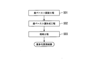
- FIG. 1 is a flowchart showing a method for producing a silver porous sintered film according to an embodiment of the present invention.
- the method for producing a porous silver sintered film of the present embodiment includes a silver paste preparation step S01, a silver paste film forming step S02, and a sintering step S03.
- Silver paste preparation step S01 In the silver paste preparation step S01, a silver paste is prepared by kneading raw material silver powder and an organic solvent.
- the silver powder preferably has an average particle size of silver particles in the range of 40 nm to 100 nm.
- the silver powder has a C 3 H 3 O 3 ⁇ ion / Ag + ion ratio (ratio of the detected amount of C 3 H 3 O 3 ⁇ ions to the detected amount of Ag + ions measured by TOF-SIMS) of 0. C 6 H 6 O 8 ⁇ ions / Ag + ion ratio (C 6 H 6 O 8 ⁇ ions relative to the detected amount of Ag + ions measured by TOF-SIMS)
- the ratio of the detection amounts is preferably in the range of 0.005 or more and 0.02 or less.
- the C 3 H 3 O 3 ⁇ ion / Ag + ion ratio is more preferably 0.2 or more and 0.5 or less.
- the C 6 H 6 O 8 ⁇ ion / Ag + ion ratio is more preferably 0.005 or more and 0.01 or less.
- a silver porous sintered film having high sinterability can be obtained by partially sintering silver powder having an average particle diameter of silver particles in the above range in the sintering step S03 described later. Further, by using silver powder having a C 3 H 3 O 3 ⁇ ion / Ag + ion ratio and a C 6 H 6 O 8 ⁇ ion / Ag + ion ratio within the above ranges, respectively, in the sintering step S03 described later. Excessive sintering of silver particles can be suppressed, and a silver porous sintered film in which silver particles are partially sintered can be obtained.
- Said silver powder is produced with the following method, for example.
- a silver salt aqueous solution and a carboxylic acid aqueous solution are simultaneously dropped into water to produce silver carboxylate particles to prepare a silver carboxylate slurry.
- a reducing agent aqueous solution is dropped into the prepared silver carboxylate slurry to obtain a mixed slurry.
- the silver carboxylate particles are reduced to produce silver particles to prepare a silver powder slurry.
- the prepared silver powder slurry is dried to obtain silver powder.
- organic matter derived from a carboxylic acid is attached to the surface of the resulting silver particles, C 3 H 3 is detected by the TOF-SIMS O 3 - Ion / Ag + ion ratios and C 6 H 6 O Silver powder having an 8 ⁇ ion / Ag + ion ratio in the above range can be obtained.
- silver salt aqueous solution for example, an aqueous solution of silver salt such as silver nitrate, silver chlorate, and silver phosphate can be used. These silver salts may be used individually by 1 type, and may be used in combination of 2 or more type.
- the carboxylic acid aqueous solution contains a carboxylic acid or a carboxylate.
- a carboxylic acid for example, glycolic acid, citric acid, malic acid, maleic acid, malonic acid, fumaric acid, succinic acid, and tartaric acid can be used.
- carboxylate ammonium salts and alkali metal salts of these carboxylic acids can be used. These carboxylic acids and carboxylates may be used alone or in combination of two or more.
- the time from dropping the aqueous silver salt solution to the formation of silver carboxylate particles is shortened, so the particle size is reduced. Small silver carboxylate particles are easily generated.
- water it is preferable to use water with a small content of ions that may adversely affect the production of silver carboxylate particles such as ion-exchanged water and distilled water.
- reducing agent aqueous solution added to the silver carboxylate slurry for example, aqueous solutions of reducing agents such as hydrazine, ascorbic acid, oxalic acid, formic acid, and salts thereof can be used.
- reducing agents such as hydrazine, ascorbic acid, oxalic acid, formic acid, and salts thereof can be used.
- salts ammonium salts and alkali metal salts can be used.
- These reducing agents may be used individually by 1 type, and may be used in combination of 2 or more type.
- a reducing slurry aqueous solution is dropped into a silver carboxylate slurry to obtain a mixed slurry.
- the holding temperature of the obtained mixed slurry is 92 ° C. or higher, silver carboxylate is easily reduced, and silver particles can be generated quickly.
- the carboxylic acid can be attached as C 3 H 3 O 3 ⁇ ions or C 6 H 6 O 8 ⁇ ions to the surface of the generated silver particles. Therefore, silver particles can be prevented from becoming coarse particles.
- the time for holding the mixed slurry at the above temperature is preferably in the range of 0.25 hours to 0.5 hours.
- the holding time is preferably 0.33 hours or more and 0.5 hours or less.
- the cooling of the silver powder slurry is preferably carried out at a temperature lowering rate at which the time for lowering the temperature to 30 ° C. is 15 minutes or less.
- a freeze drying method for example, a vacuum drying method, or a heat drying method can be used.
- a vacuum drying method for example, a vacuum drying method, or a heat drying method.
- the organic solvent of the silver paste is not particularly limited as long as it can be removed by evaporation in the sintering step S03 described later.
- the organic solvent for example, alcohol solvents, glycol solvents, acetate solvents, hydrocarbon solvents, and amine solvents can be used.
- alcohol solvents include ⁇ -terpineol and isopropyl alcohol.
- glycol solvents include ethylene glycol, diethylene glycol, and polyethylene glycol.
- An example of an acetate solvent is butyl tolcarbate.
- the hydrocarbon solvent include decane, dodecane, and tetradecane.
- the amine solvent include hexylamine, octylamine, and dodecylamine. These organic solvents may be used individually by 1 type, and may be used in combination of 2 or more type.
- the silver particle content of the silver paste is preferably in the range of 70% by mass to 95% by mass. If it is less than 70% by mass, the amount of the solvent is relatively increased, the viscosity becomes too low, and the formability of the silver paste film may be significantly lowered in the silver paste film forming step S02 described later. On the other hand, when the content of silver particles exceeds 95% by mass, the viscosity of the silver paste becomes too high, and the fluidity of the silver paste is remarkably lowered, making it difficult to form a silver paste layer.
- a silver paste film is formed using the silver paste prepared in the silver paste preparing step S01. Specifically, a silver paste is applied on the substrate to form a silver paste film.
- the film thickness of the silver paste film is preferably in the range of 10 ⁇ m to 100 ⁇ m.
- the substrate has a flat surface and can be easily separated from the silver porous sintered film generated in the sintering step S03.
- a resin substrate examples include a fluororesin substrate and a silicone resin substrate.
- the metal substrate examples include a copper substrate, an aluminum substrate, and a stainless steel substrate.
- the ceramic substrate examples include a glass substrate, an alumina substrate, a silicon oxide substrate, and a silicon nitride substrate.
- the silver paste application method is not particularly limited, and various methods used as a silver paste application method can be used.
- Coating methods include, for example, printing method, dispensing method, pin transfer method, roll coating method, dip coating method, air knife coating method, blade coating method, wire bar coating method, slide hopper coating method, extrusion coating method, curtain A coating method, a spin coating method, a spray coating method, a gravure coating method, and a comma coating method can be used.
- the silver paste film formed in the silver paste film forming step S02 is heated to remove the solvent of the silver paste film and partially sinter silver particles to produce a silver porous sintered film.
- the heating temperature of the silver paste film is, for example, in the range of 100 ° C. or higher and 200 ° C. or lower. If the heating temperature is too low, the silver particles of the silver paste film are difficult to sinter, the mechanical strength of the silver porous sintered film is lowered, and it may not be handled as a self-supporting film.
- the heating temperature exceeds 200 ° C., the silver particles in the silver paste layer are excessively sintered, the silver particles grow, and the sinterability of the resulting porous silver sintered film may be reduced. is there.
- the heating time is preferably 5 to 30 minutes.
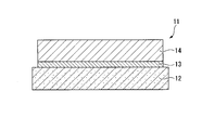
- FIG. 2 is a cross-sectional view of a joined body according to an embodiment of the present invention.
- the joined body 11 includes a first member 12 and a second member 14 joined to one surface (upper surface in FIG. 1) of the first member via a joining layer 13. Yes.
- an insulating circuit substrate such as a DBA (Direct bonded Aluminum) substrate or a DBC (Direct Bonded Copper) substrate can be used.
- an electronic device such as an LED element or a power semiconductor chip can be used.
- the joining layer 13 is a silver particle sintered body formed by heating the silver porous sintered film to sinter silver particles.
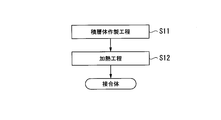
- FIG. 3 is a flowchart showing a method for manufacturing a joined body according to an embodiment of the present invention. As shown in FIG. 3, the method for manufacturing a joined body according to the present embodiment includes a laminate manufacturing step S ⁇ b> 11 and a heating step S ⁇ b> 12.
- the first member 12 and the second member 14 are laminated via a silver porous sintered film to produce a laminated body.
- the laminate can be produced by laminating the first member 12, the silver porous sintered film, and the second member 14 in this order.
- the film with high affinity with silver is formed in the surface of the side which contacts a silver porous sintered film.
- the coating is preferably a silver film or a gold film.
- a method for forming the film a plating method or a sputtering method can be used.
- the bonding force between the bonding layer 13 (silver particle sintered body) generated in the heating step S12 described later and the first member 12 and the second member 14 is increased, and the obtained bonded body 11 Bond strength (shear strength) is improved.
- Heating step S12 In heating process S12, the laminated body obtained by the above-mentioned laminated body preparation process S01 is heated, and the silver particle of a silver porous sintered film is further sintered, and the joining layer 13 is formed. Thereby, the joined body 11 in which the first member 12 and the second member 14 are joined via the joining layer 13 is obtained.
- the heating temperature of the laminate is, for example, in the range of 150 ° C. or higher and 250 ° C. or lower, preferably in the range of 170 ° C. or higher and 230 ° C. or lower.
- the heating temperature is lower than 150 ° C., the silver particles of the silver porous sintered film are difficult to sinter, and the bonding layer 13 may not be formed.
- the heating temperature exceeds 250 ° C., the first member 12 and the second member 14 may be deteriorated by heat.
- the stacking direction is a direction perpendicular to the surface where the first member 12 and the second member 14 are in contact with the silver porous sintered film.
- the crystallite size is in the range of 60 nm to 150 nm, the strength is high and it can be handled as a self-supporting bonding material. It becomes possible. Further, silver particles have high sinterability, and it becomes possible to form a silver particle sintered body with high density and high bonding strength by heating at a relatively low temperature. Further, the C 3 H 7 + ion / Ag + ion ratio is in the range of 0.10 to 0.35, and the C 2 H ⁇ ion / Ag ⁇ ion ratio is in the range of 0.9 to 3.7.
- the surface of the silver porous sintered film is not easily sulfided, and the sinterability of the silver particles can be maintained for a long period of time. Moreover, it becomes possible to reliably form a dense silver particle sintered body having a high bonding strength by heating at a relatively low temperature.
- a bonded body having a high bonding strength is manufactured by heating at a relatively low temperature. It becomes possible.
- a stacked body is manufactured by stacking the first member 12, the silver porous sintered film, and the second member 14 in this order.
- a stacked body is manufactured by stacking the first member 12, the silver porous sintered film, and the second member 14 in this order.
- an insulating circuit board such as a DBA board or a DBC board
- an insulating circuit board with a silver porous sintered film in which a silver porous sintered film is formed on the surface of the insulating circuit board (silver porous sintered film) Insulated circuit board) is prepared.
- the insulated circuit board with a silver porous sintered film can be produced by the following method. A silver paste is applied to the surface of the insulating circuit substrate to form a silver paste film. Next, the silver paste film is heated to remove the solvent of the silver paste film and partially sinter the silver particles. Thereby, an insulated circuit board with a silver porous sintered film (insulated circuit board having a silver porous sintered film) can be produced.
- a glass container containing 1200 g of ion-exchanged water maintained at 50 ° C. 900 g of silver nitrate aqueous solution maintained at 50 ° C. and 600 g of glycolic acid aqueous solution maintained at 50 ° C. are taken over 5 minutes using a tube pump.
- a silver glycolate slurry was prepared. The prepared silver glycolate slurry was air-cooled and the temperature was cooled to 20 ° C.
- the mixed slurry was heated to a temperature of 92 ° C. at a rate of temperature increase of 15 ° C./hour and heat-treated at a temperature of 92 ° C. (maximum temperature) for 0.33 hours to obtain a silver powder slurry.
- the resulting silver powder slurry was cooled to 30 ° C. over 15 minutes.
- the silver powder slurry was put in a centrifuge and centrifuged at a rotational speed of 1000 rpm for 10 minutes. The supernatant liquid (liquid layer) was removed, and the remaining solid content (silver powder) was washed with water, and then dried by freeze-drying for 30 hours to recover the silver powder.
- the recovered silver powder was classified as Class I silver powder.
- a silver powder of class II was obtained in the same manner as in class I except that a formic acid aqueous solution (formic acid concentration: 58% by mass) was used as the reducing agent aqueous solution.
- classification VII As silver powder of classification VII, commercially available silver powder (Mitsui Kinzoku Kogyo Co., Ltd., “HP02”) was prepared.
- Silver powder was mixed with an epoxy resin, and the obtained mixture was cured to prepare a sample for measuring silver particle diameter.
- the central portion of the silver particle diameter measurement sample was cut, and the cut surface was polished by an argon ion beam.
- the polished processed surface was observed with a scanning electron microscope (SEM), and 1000 or more silver particles were randomly selected.
- SEM scanning electron microscope
- the detected amounts of Ag + ion, C 3 H 3 O 3 ⁇ ion, C 6 H 6 O 8 ⁇ ion were determined, and C 3 H 3 O 3 ⁇ ion and C 6 H 6 O were obtained.
- the detected amount of 8 ⁇ ions was divided by the detected amount of Ag + ions, and the C 3 H 3 O 3 ⁇ ion / Ag + ion ratio and the C 6 H 6 O 8 ⁇ ion / Ag + ion ratio were calculated. .
- the above silver paste was printed on a glass substrate using a 2.5 mm ⁇ 2.5 mm ⁇ 0.05 mm thick metal mask plate to form a 0.05 mm thick silver paste film (silver paste) Film forming step S02).
- the glass substrate on which the silver paste film is formed is put into a blower dryer, the silver paste film is dried under a sintering condition of a heating temperature of 150 ° C. and a heating time of 15 minutes, and the silver particles are partially sintered.
- a silver porous sintered film was produced (sintering step S03).
- the glass substrate was taken out from the blower dryer and allowed to cool to room temperature, and then the silver porous sintered film was peeled off from the glass substrate to obtain a silver porous sintered film.
- the film thickness of the obtained silver porous sintered film was 0.04 mm.
- a silicon element (2.5 mm ⁇ 2.5 mm) having a silver sputtered bottom surface and a copper plate (2.5 mm ⁇ 2.5 mm) plated with silver were prepared.
- the bottom surface of the silicon element that was sputtered with silver and the surface of the copper plate that had been subjected to silver plating were laminated through the above-mentioned silver porous sintered film to obtain a laminate (laminate production step S11).
- the obtained laminate was heated from room temperature to 200 ° C. at a rate of 30 ° C./min in an air atmosphere while applying a 10 MPa load in the laminating direction using a pressure die bonder, and then at 200 ° C. for 15 Heated for minutes.
- the joined body was obtained by the above (heating process S12). In the obtained joined body, the thickness of the joining layer was 0.03 mm.
- the filling rate was determined from a cross-sectional image of the silver porous sintered film.
- the cross section of the silver porous sintered film was processed by CP (Cross section Polish).
- the cross section of the silver porous sintered film was photographed at a magnification of 1000 times using an SEM.
- the obtained cross-sectional image was binarized using image processing software (Image J). In the binarized image, the area of the silver part displayed in white was measured, and the area ratio of the silver part in the entire visual field was calculated as the filling rate.
- Crystallite size The crystallite size was determined from the X-ray diffraction pattern.
- the X-ray diffraction pattern was measured under the following measurement conditions using an X-ray diffraction apparatus (D8 ADVANCE manufactured by Bruker AXS). Measurement conditions Target: Cu Tube voltage: 40 kV Tube current: 40 mA Irradiation X-ray size: 2 mm ⁇ or less Scanning range: 30-140 deg. Step width: 0.02 deg.
- the obtained X-ray diffraction pattern was analyzed by the Pawley method using analysis software (Burker AXS, TOPAS: Version 5), and the crystallite size of the silver particles was calculated from the Lorentz function component.
- the profile function was fixed to the value obtained using the X-ray diffraction pattern of the standard sample (NIST SRM640d) measured in advance.
- the shear strength was measured by the following method. The force required to break the bonding layer formed between the copper plate and the silicon element was measured by a bonding tester (manufactured by RHESCA). This measured value was divided by the bonding area (the area of the bottom surface of the silicon element) to obtain the shear strength. In addition, seven joining layers were produced and measured in the same procedure, and the average value of the measured values was divided by the joining area to obtain the shear strength.
- the thickness of the joining layer was 0.03 mm.
- the shear strength of the obtained joined body was measured in the same manner as described above. The results are shown in Table 2 below.
- the C 3 H 7 + ion / Ag + ion ratio and the C 2 H ⁇ ion / Ag ⁇ ion ratio were higher than the range of this embodiment.
- the bonded body manufactured using the silver porous sintered film of Comparative Example 1 had a lower shear strength than the bonded body of Reference Example 1 manufactured using a silver paste. This is considered to be due to the fact that the amount of the organic compound covering the silver porous sintered film is large, so that the sinterability of the silver particles is lowered.
- the C 3 H 7 + ion / Ag + ion ratio and the C 2 H ⁇ ion / Ag ⁇ ion ratio were lower than the range of this embodiment.
- the bonded body manufactured using the silver porous sintered film of Comparative Example 2 had a lower shear strength than the bonded body of Reference Example 1 manufactured using a silver paste. This is because the amount of organic compound that covers the silver porous sintered film is small, so the surface of the silver porous sintered film is sulfided between the production of the silver porous sintered film and the manufacture of the joined body. This is thought to be because the silver particles became difficult to sinter.
- the crystallite size is larger than the range of the present embodiment, and the C 3 H 7 + ion / Ag + ion ratio and the C 2 H ⁇ ion / Ag ⁇ ion ratio are implemented in this embodiment. It was lower than the range of morphology.
- the bonded body manufactured using the silver porous sintered film of Comparative Example 3 had a lower shear strength than the bonded body of Reference Example 1 manufactured using a silver paste. This is presumably because the sinterability of the silver particles was greatly reduced because the surface of the silver porous sintered film was sulfided and the crystallite size was coarse.
- Comparative Example 4 the heating temperature of the silver paste film was set to 80 ° C., but the heating temperature became too low, the silver particles were only partially sintered, the crystallite size was small, and the amount of organic compound was large. It was. Therefore, a self-supporting silver porous sintered film could not be obtained. Therefore, measurements other than the silver crystallite size and the amount of organic compound were not performed. Further, in Comparative Example 5, silver powder having an average particle diameter of 200 nm was used, but the silver particles have low sinterability, and when the heating temperature is 150 ° C., the silver particles do not sinter and the self-supporting silver porous A quality sintered film could not be obtained. Also, the crystallite size of silver increased. Therefore, measurements other than the silver crystallite size and the amount of organic compound were not performed.
- the crystallite size is in the range of the present embodiment, and the present invention example in which the C 3 H 7 + ion / Ag + ion ratio and the C 2 H ⁇ ion / Ag ⁇ ion ratio are in the range of the present embodiment. It was confirmed that the bonded body manufactured using 1 to 8 silver porous sintered films had higher shear strength than the bonded body of Reference Example 1 manufactured using silver paste. This is because in the silver porous sintered films of Invention Examples 1 to 8, since the organic solvent does not volatilize when heated during the manufacture of the joined body, pores are not easily generated inside, and a dense joining layer is formed. It is believed that there is.
- the measured value of the shear strength is 65 MPa
- the measured value of the shear strength has a variation of about ⁇ 5 MPa to +5 MPa.
- the shear strength 60 MPa of Invention Examples 1, 5, and 6 and the shear strength 70 MPa of Invention Example 4 are substantially the same value.
- the amount of organic compound was different, but the shear strength was the same. This is presumed to be because there was no significant difference in sinterability between Invention Examples 2 and 3.
- the cross section was polished to expose the cross section of the silver porous sintered film.
- the cross section was observed using SEM.
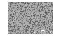
- FIG. 4 the SEM photograph of the cross section of a silver porous sintered film is shown.
- the cross section was grind
- the cross section was observed using SEM.
- FIG. 5 the SEM photograph of the cross section of a joining layer is shown.
- the silver porous sintered film of FIG. 4 has a structure in which silver particles are partially sintered and continuous pores are formed between the partially sintered silver particles. confirmed. Further, from the SEM photograph of the bonding layer in FIG. 5, it was confirmed that the silver porous sintered film was further sintered with silver particles by heating to form a dense silver particle sintered body (bonding layer).
- the silver porous sintered film of the present embodiment a bonded body having a dense silver particle sintered body (bonding layer) with high bonding strength can be produced by heating at a relatively low temperature.
- the silver porous sintered film of the present embodiment is formed by joining two or more parts in the process of assembling and mounting electronic parts such as LED (light emitting diode) elements and power semiconductor chips. It can use suitably for the process to manufacture.
Landscapes
- Chemical & Material Sciences (AREA)
- Engineering & Computer Science (AREA)
- Mechanical Engineering (AREA)
- Materials Engineering (AREA)
- Manufacturing & Machinery (AREA)
- Metallurgy (AREA)
- Organic Chemistry (AREA)
- Composite Materials (AREA)
- Powder Metallurgy (AREA)
Abstract
この銀多孔質焼結膜は、銀粒子を焼結させてなり、結晶子サイズが60~150nmであり、飛行時間型二次イオン質量分析法によって測定されるAg+イオンの検出量に対するC3H7 +イオンの検出量の比が0.10~0.35であり、かつ飛行時間型二次イオン質量分析法によって測定されるAg-イオンの検出量に対するC2H-イオンの検出量の比が0.9~3.7である。
Description
本発明は、銀多孔質焼結膜およびこれを用いた接合体の製造方法に関する。
本願は、2018年3月28日に日本に出願された特願2018-061321号、及び2019年3月18日に日本に出願された特願2019-050381号に基づき優先権を主張し、その内容をここに援用する。
本願は、2018年3月28日に日本に出願された特願2018-061321号、及び2019年3月18日に日本に出願された特願2019-050381号に基づき優先権を主張し、その内容をここに援用する。
LED(発光ダイオード)素子やパワー半導体チップなどの電子部品の組立てや実装等の工程において、2つ以上の部品を接合した接合体を製造する場合、一般的に接合材が用いられる。このような接合材として、銀粉末を有機溶媒に分散させた銀ペーストが知られている。この銀ペーストは、一方の部品と他方の部品とを銀ペーストを介して積層し、得られた積層体を加熱して、銀ペースト中の銀粒子を焼結させて接合層(銀粒子の焼結体)を形成することによって部品を接合する。例えば、特許文献1には、粒度分布において粒径20~70nmの範囲内の第1ピークと、粒径200~500nmの範囲内の第2ピークとを有する微細な銀粉と、所定のアルキルアミンと、還元性有機溶媒とを含むペースト状の接合材が開示されている。
また、接合材として、銀粒子を部分的に焼結させた銀多孔質焼結膜も知られている。この銀多孔質焼結膜を介して、一方の部品と他方の部品とを積層する。得られた積層体を加熱して、銀多孔質焼結膜中の銀粒子をさらに焼結させて接合層(銀粒子の焼結体)を形成することによって部品を接合する。例えば、特許文献2には、銀の多孔質体である多孔質銀で形成され、緻密度が40~72体積%の自立膜であって、前記多孔質銀の銀結晶の平均結晶粒径が1.7~2.6μmであり、25℃における三点曲げ試験から得られる曲げ弾性率が16~24GPa、最大曲げ強度が100MPa以上、破断曲げひずみが1.3%以上である多孔質銀製シートが開示されている。
銀多孔質焼結膜は、銀ペーストと比較すると、接合体の製造時の加熱の際に有機溶媒が揮発しないなどの利点がある。しかしながら、特許文献2に記載の多孔質銀製シートは、銀結晶の平均結晶粒径が1.7~2.6μmと比較的大きいため、例えば、200℃の低温度の加熱では、銀粒子が焼結しにくく、緻密で接合強度が高い接合層を形成するのが困難となる場合があった。
この発明は、前述した事情に鑑みてなされたものであって、その目的は、比較的低温度の加熱によって、緻密で接合強度が高い銀粒子焼結体(接合層)を形成することができる銀多孔質焼結膜およびこの銀多孔質焼結膜を用いた接合体の製造方法を提供することにある。
上記の課題を解決するために、本発明の一態様に係る銀多孔質焼結膜は、銀粒子を焼結させてなる銀多孔質焼結膜であって、結晶子サイズが60nm以上150nm以下の範囲内にあり、飛行時間型二次イオン質量分析法によって測定されるAg+イオンの検出量に対するC3H7
+イオンの検出量の比(C3H7
+イオン/Ag+イオン比)が0.10以上0.35以下の範囲内にあって、かつ飛行時間型二次イオン質量分析法によって測定されるAg-イオンの検出量に対するC2H-イオンの検出量の比(C2H-イオン/Ag-イオン比)が0.9以上3.7以下の範囲内にあることを特徴としている。
このような構成とされた本発明の一態様に係る銀多孔質焼結膜は、結晶子サイズが上記の範囲内とされているので、強度が高く、自立した接合材として扱うことが可能となる。また焼結性が高く、比較的低温度の加熱によって、緻密で接合強度が高い銀粒子焼結体を形成することが可能となる。さらに、C3H7
+イオン/Ag+イオン比とC2H-イオン/Ag-イオン比がそれぞれ上記の範囲内とされているので、銀多孔質焼結膜の表面が硫化しにくくなり、焼結性を長期間にわたって維持することができる。このため、比較的低温度の加熱によって緻密で接合強度が高い銀粒子焼結体をより確実に形成することが可能となる。
本発明の一態様に係る接合体の製造方法は、第1部材と第2部材とが接合された接合体の製造方法であって、前記第1部材と前記第2部材とを、上述の銀多孔質焼結膜を介して積層して積層体を得る工程と、前記積層体を加熱する工程と、を有することを特徴としている。
このような構成とされた本発明の一態様に係る接合体の製造方法によれば、接合材として、上述の銀多孔質焼結膜を用いるので、比較的低温度の加熱によって、接合強度(シェア強度)が高い接合体を製造することが可能となる。
本発明の一態様によれば、比較的低温度の加熱によって、緻密で接合強度が高い銀粒子焼結体(接合層)を形成することができる銀多孔質焼結膜およびこの銀多孔質焼結膜を用いた接合体の製造方法を提供することが可能となる。
以下、本発明の実施形態である銀多孔質焼結膜及び接合体の製造方法について、添付した図面を参照して詳細に説明する。なお、以下の説明で用いる図面は、特徴をわかりやすくするために、便宜上特徴となる部分を拡大して示している場合があり、各構成要素の寸法比率などが実際と同じであるとは限らない。
<銀多孔質焼結膜>
本実施形態の銀多孔質焼結膜は、銀粒子を焼結させてなる銀多孔質焼結膜である。すなわち、銀多孔質焼結膜は、銀粒子と、銀粒子の焼結体とからなる銀の多孔質体である。銀多孔質焼結膜を構成する銀の結晶子サイズは60nm以上150nm以下の範囲内とされている。また、C3H7 +イオン/Ag+イオン比(飛行時間型二次イオン質量分析法(TOF-SIMS)によって測定されるAg+イオンの検出量に対するC3H7 +イオンの検出量の比)が0.10以上0.35以下の範囲内にあって、かつC2H-イオン/Ag-イオン比(TOF-SIMSによって測定されるAg-イオンの検出量に対するC2H-イオンの検出量の比)が0.9以上3.7以下の範囲内とされている。なお、イオンの検出量の単位は、強度のカウント数で表される。
本実施形態の銀多孔質焼結膜は、銀粒子を焼結させてなる銀多孔質焼結膜である。すなわち、銀多孔質焼結膜は、銀粒子と、銀粒子の焼結体とからなる銀の多孔質体である。銀多孔質焼結膜を構成する銀の結晶子サイズは60nm以上150nm以下の範囲内とされている。また、C3H7 +イオン/Ag+イオン比(飛行時間型二次イオン質量分析法(TOF-SIMS)によって測定されるAg+イオンの検出量に対するC3H7 +イオンの検出量の比)が0.10以上0.35以下の範囲内にあって、かつC2H-イオン/Ag-イオン比(TOF-SIMSによって測定されるAg-イオンの検出量に対するC2H-イオンの検出量の比)が0.9以上3.7以下の範囲内とされている。なお、イオンの検出量の単位は、強度のカウント数で表される。
銀多孔質焼結膜は、銀粒子が部分的に焼結し、部分的に焼結した銀粒子間に連続気孔が形成された構造を有する多孔質体であることが好ましい。この銀粒子が部分的に焼結した構造を有する銀多孔質焼結膜を加熱することによって、さらに銀粒子の焼結が進み、緻密で接合強度が高い銀粒子焼結体(接合層)を形成することが可能となる。
銀多孔質焼結膜は、結晶子サイズが60nm以上とされているので、銀多孔質焼結膜の強度が高く、自立した接合材として扱うことが可能となる。また、結晶子サイズが150nm以下とされているので、焼結性が高く、比較的低温度の加熱によって、緻密で接合強度が高い銀粒子焼結体を形成することが可能となる。
なお、結晶子サイズは、X線回折パターンから求めた値である。
なお、結晶子サイズは、X線回折パターンから求めた値である。
銀多孔質焼結膜は、C3H7
+イオン/Ag+イオン比が0.10以上0.35以下の範囲内にあって、かつC2H-イオン/Ag-イオン比が0.9以上3.7以下の範囲内とされている。C3H7
+イオンおよびC2H-イオンは、銀多孔質焼結膜の表面を被覆している有機化合物に由来すると考えられる。C3H7
+イオン/Ag+イオン比が0.10以上でC2H-イオン/Ag-イオン比が0.9以上であると、銀多孔質焼結膜の表面を被覆する有機化合物によって、銀多孔質焼結膜の表面が硫化しにくくなり、銀粒子の焼結性を長期間にわたって維持することができる。また、C3H7
+イオン/Ag+イオン比が0.35以下でC2H-イオン/Ag-イオン比が3.7以下であると、銀多孔質焼結膜の表面を被覆する有機化合物によって、銀多孔質焼結膜の焼結性が低下することが抑えられ、比較的低温度の加熱によって、緻密で接合強度が高い銀粒子焼結体を形成することが可能となる。
C3H7 +イオン/Ag+イオン比は、好ましくは0.20以上3.5以下であり、C2H-イオン/Ag-イオン比は、好ましくは2.5以上3.7以下である。
C3H7 +イオン/Ag+イオン比は、好ましくは0.20以上3.5以下であり、C2H-イオン/Ag-イオン比は、好ましくは2.5以上3.7以下である。
銀多孔質焼結膜は、充填率が50%以上70%以下の範囲内にあることが好ましい。充填率が50%以上であると、銀多孔質焼結膜の強度が高くなり、取扱いが容易になる。また、充填率が70%以下であると、銀粒子の焼結性が高くなり、低温度での加熱によって緻密でかつ接合強度が高い銀粒子焼結体を形成することができる。銀多孔質焼結膜の接合強度の観点から、充填率は55%以上であることがより好ましい。また、焼結性の観点から、充填率は65%以下であることが好ましい。
なお、銀多孔質焼結膜の充填率は、銀多孔質焼結膜の断面画像から求めた値である。
なお、銀多孔質焼結膜の充填率は、銀多孔質焼結膜の断面画像から求めた値である。
<銀多孔質焼結膜の製造方法>
次に、本実施形態の銀多孔質焼結膜の製造方法を説明する。図1は、本発明の一実施形態に係る銀多孔質焼結膜の製造方法を示すフロー図である。
本実施形態の銀多孔質焼結膜の製造方法は、図1に示すように、銀ペースト調製工程S01と、銀ペースト膜形成工程S02と、焼結工程S03とを含む。
次に、本実施形態の銀多孔質焼結膜の製造方法を説明する。図1は、本発明の一実施形態に係る銀多孔質焼結膜の製造方法を示すフロー図である。
本実施形態の銀多孔質焼結膜の製造方法は、図1に示すように、銀ペースト調製工程S01と、銀ペースト膜形成工程S02と、焼結工程S03とを含む。
(銀ペースト調製工程S01)
銀ペースト調製工程S01では、原料の銀粉と有機溶媒とを混練して、銀ペーストを調製する。
銀ペースト調製工程S01では、原料の銀粉と有機溶媒とを混練して、銀ペーストを調製する。
銀粉は、銀粒子の平均粒径が40nm以上100nm以下の範囲内にあることが好ましい。また、銀粉は、C3H3O3
-イオン/Ag+イオン比(TOF-SIMSによって測定されるAg+イオンの検出量に対するC3H3O3
-イオンの検出量の比)が0.2以上1.0以下の範囲内にあって、C6H6O8
-イオン/Ag+イオン比(TOF-SIMSによって測定されるAg+イオンの検出量に対するC6H6O8
-イオンの検出量の比)が0.005以上0.02以下の範囲内にあることが好ましい。C3H3O3
-イオン/Ag+イオン比は、より好ましくは0.2以上0.5以下である。C6H6O8
-イオン/Ag+イオン比は、より好ましくは0.005以上0.01以下である。
銀粒子の平均粒径が上記の範囲内にある銀粉を、後述の焼結工程S03にて部分的に焼結させることにより、焼結性が高い銀多孔質焼結膜を得ることができる。また、C3H3O3
-イオン/Ag+イオン比とC6H6O8
-イオン/Ag+イオン比がそれぞれ上記の範囲内にある銀粉を用いることにより、後述の焼結工程S03において銀粒子の過剰な焼結を抑制することができ、銀粒子が部分的に焼結した銀多孔質焼結膜を得ることが可能となる。
上記の銀粉は、例えば、以下の方法で作製される。銀塩水溶液とカルボン酸類水溶液とを水中に同時に滴下して、カルボン酸銀粒子を生成させてカルボン酸銀スラリーを調製する。次いで、調製したカルボン酸銀スラリーに還元剤水溶液を滴下して混合スラリーを得る。得られた混合スラリーを、92℃以上95℃以下の範囲内の温度で保持することにより、カルボン酸銀粒子を還元して銀粒子を生成させて銀粉スラリーを調製する。そして調製した銀粉スラリーを乾燥して銀粉を得る。この製造方法によれば、生成する銀粒子の表面にカルボン酸に由来する有機物が付着し、TOF-SIMSで検出されるC3H3O3
-イオン/Ag+イオン比とC6H6O8
-イオン/Ag+イオン比がそれぞれ上記の範囲内にある銀粉を得ることができる。
銀塩水溶液としては、例えば、硝酸銀、塩素酸銀、リン酸銀などの銀塩の水溶液を用いることができる。これらの銀塩は1種を単独で使用してもよいし、2種以上を組み合わせて使用してもよい。
カルボン酸類水溶液は、カルボン酸もしくはカルボン酸塩を含む。カルボン酸としては、例えば、グリコール酸、クエン酸、リンゴ酸、マレイン酸、マロン酸、フマル酸、コハク酸、酒石酸を用いることができる。カルボン酸塩としては、これらのカルボン酸のアンモニウム塩、アルカリ金属塩を用いることができる。これらのカルボン酸およびカルボン酸塩は1種を単独で使用してもよいし、2種以上を組み合わせて使用してもよい。
水中に同時に滴下する銀塩水溶液とカルボン酸類水溶液の量の割合は、銀とカルボン酸の当量比[=(銀イオンの価数:1価×モル数)/(カルボン酸の価数×モル数)]として、1.1以上2.0以下の範囲内とすることが好ましい。この場合、滴下の進行に伴って、水中にフリーなカルボン酸の量が増加することによって、銀塩水溶液を滴下してからカルボン酸銀粒子が生成するまでの時間が短くなるので、粒子径が小さいカルボン酸銀粒子が生成し易くなる。水としては、イオン交換水、蒸留水などのカルボン酸銀粒子の生成に悪影響を与えるおそれのあるイオンの含有量が少ない水を用いることが好ましい。
カルボン酸銀スラリーに添加する還元剤水溶液としては、例えば、ヒドラジン、アスコルビン酸、シュウ酸、ギ酸、及びこれらの塩類などの還元剤の水溶液を用いることができる。塩類としては、アンモニウム塩、アルカリ金属塩を用いることができる。これらの還元剤は1種を単独で使用してもよいし、2種以上を組み合わせて使用してもよい。
上記の銀粉の製造方法では、カルボン酸銀スラリーに還元剤水溶液を滴下して混合スラリーを得る。得られた混合スラリーの保持温度を92℃以上とすることにより、カルボン酸銀が還元されやすくなり、銀粒子を速やかに生成させることができる。また、混合スラリーの保持温度を95℃以下とすることにより、生成した銀粒子の表面に、カルボン酸をC3H3O3
-イオンもしくはC6H6O8
-イオンとして付着させることができるので、銀粒子が粗大粒子となるのを防止することができる。混合スラリーを上記の温度で保持する時間は、0.25時間以上0.5時間以下の範囲内にあることが好ましい。保持時間を0.25時間以上とすることにより、カルボン酸銀を確実に還元させることができ、銀粒子を安定して生成させることができる。また、保持時間を0.5時間以下にすることにより、生成した銀粒子が粗大粒子となるのを防止することができる。保持時間は、好ましくは0.33時間以上0.5時間以下である。
調製された銀粉スラリーは、銀粒子が粗大粒子となるのを防止するために、速やかに冷却することが好ましい。銀粉スラリーの冷却は、30℃まで降温する時間が15分以下となる降温速度により行なうことが好ましい。
銀粉スラリーの乾燥方法としては、例えば、凍結乾燥法、減圧乾燥法、加熱乾燥法を用いることができる。銀粉スラリーを乾燥する前に、遠心分離機やデカンテーションにより、銀粉スラリー中の水分を除去することが好ましい。
銀ペーストの有機溶媒は、後述の焼結工程S03において、蒸発除去できるものであれば特に制限はない。有機溶媒としては、例えば、アルコール系溶媒、グリコール系溶媒、アセテート系溶媒、炭化水素系溶媒、アミン系溶媒を用いることができる。アルコール系溶媒の例としては、α-テルピネオール、イソプロピルアルコールが挙げられる。グリコール系溶媒の例としては、エチレングリコール、ジエチレングリコール、ポリエチレングリコールが挙げられる。アセテート系溶媒の例としては、酢酸ブチルトールカルビテートが挙げられる。炭化水素系溶媒の例としては、デカン、ドデカン、テトラデカンが挙げられる。アミン系溶媒の例としては、ヘキシルアミン、オクチルアミン、ドデシルアミンが挙げられる。これらの有機溶媒は1種を単独で使用してもよいし、2種以上を組み合わせて使用してもよい。
銀ペーストを100質量%としたとき、銀ペーストの銀粒子の含有量は、70質量%以上95質量%以下の範囲内の量であることが好ましい。70質量%未満であると、相対的に溶媒の量が多くなり、粘度が低くなりすぎて、後述の銀ペースト膜形成工程S02において、銀ペースト膜の成形性が著しく低下するおそれがある。一方、銀粒子の含有量が95質量%を超えると、銀ペーストの粘度が高くなりすぎて、銀ペーストの流動性が著しく低下し、銀ペースト層を形成しにくくなるおそれがある。
(銀ペースト膜形成工程S02)
銀ペースト膜形成工程S02では、上記銀ペースト調製工程S01で調製した銀ペーストを用いて銀ペースト膜を形成する。具体的には、基板の上に、銀ペーストを塗布して銀ペースト膜を形成する。銀ペースト膜の膜厚は、10μm以上100μm以下の範囲内にあることが好ましい。
銀ペースト膜形成工程S02では、上記銀ペースト調製工程S01で調製した銀ペーストを用いて銀ペースト膜を形成する。具体的には、基板の上に、銀ペーストを塗布して銀ペースト膜を形成する。銀ペースト膜の膜厚は、10μm以上100μm以下の範囲内にあることが好ましい。
基板としては、表面が平坦で、焼結工程S03で生成する銀多孔質焼結膜との剥離が容易なものであることが好ましい。基板としては、樹脂基板、金属基板、セラミック基板を用いることができる。樹脂基板の例としては、フッ素樹脂基板、シリコーン樹脂基板を挙げることができる。金属基板の例としては、銅基板、アルミニウム基板、ステンレス基板を挙げることができる。セラミック基板の例としては、ガラス基板、アルミナ基板、酸化ケイ素基板、窒化ケイ素基板を挙げることができる。
銀ペーストの塗布方法は、特に制限はなく、銀ペーストの塗布方法として利用されている各種の方法を用いることができる。塗布方法としては、例えば、印刷法、ディスペンス法、ピン転写法、ロールコート法、ディップコート法、エアーナイフコート法、ブレードコート法、ワイヤーバーコート法、スライドホッパコート法、エクストルージョンコート法、カーテンコート法、スピンコート法、スプレーコート法、グラビアコート法、コンマコート法を用いることができる。
(焼結工程S03)
焼結工程S03では、上記銀ペースト膜形成工程S02で形成した銀ペースト膜を加熱して、銀ペースト膜の溶媒を除去すると共に銀粒子を部分的に焼結させて銀多孔質焼結膜を生成させる。銀ペースト膜の加熱温度は、例えば、100℃以上200℃以下の範囲内である。加熱温度が低くなりすぎると、銀ペースト膜の銀粒子が焼結しにくくなり、銀多孔質焼結膜の機械強度が低下し、自立膜として取り扱えなくなるおそれがある。一方、加熱温度が200℃を超えると、銀ペースト層の銀粒子の焼結が過剰に進行して、銀粒子が粒成長し、得られる銀多孔質焼結膜の焼結性が低下するおそれがある。加熱時間は5~30分であることが好ましい。
焼結工程S03では、上記銀ペースト膜形成工程S02で形成した銀ペースト膜を加熱して、銀ペースト膜の溶媒を除去すると共に銀粒子を部分的に焼結させて銀多孔質焼結膜を生成させる。銀ペースト膜の加熱温度は、例えば、100℃以上200℃以下の範囲内である。加熱温度が低くなりすぎると、銀ペースト膜の銀粒子が焼結しにくくなり、銀多孔質焼結膜の機械強度が低下し、自立膜として取り扱えなくなるおそれがある。一方、加熱温度が200℃を超えると、銀ペースト層の銀粒子の焼結が過剰に進行して、銀粒子が粒成長し、得られる銀多孔質焼結膜の焼結性が低下するおそれがある。加熱時間は5~30分であることが好ましい。
<接合体>
次に、本実施形態の接合体について説明する。
図2は、本発明の一実施形態である接合体の断面図である。
図2に示すように、接合体11は、第1部材12と、第1部材の一方の面(図1において上面)に接合層13を介して接合された第2部材14と、を備えている。
次に、本実施形態の接合体について説明する。
図2は、本発明の一実施形態である接合体の断面図である。
図2に示すように、接合体11は、第1部材12と、第1部材の一方の面(図1において上面)に接合層13を介して接合された第2部材14と、を備えている。
第1部材12としては、例えば、DBA(Direct bonded Aluminum)基板やDBC(Direct Bonded Copper)基板などの絶縁回路基板を用いることができる。また、第2部材14としては、例えば、LED素子やパワー半導体チップなどの電子機器を用いることができる。
接合層13は、上記の銀多孔質焼結膜を加熱して、銀粒子を焼結させることによって形成した銀粒子焼結体である。
<接合体の製造方法>
次に、本実施形態の接合体の製造方法について説明する。
図3は、本発明の一実施形態に係る接合体の製造方法を示すフロー図である。
本実施形態の接合体の製造方法は、図3に示すように、積層体作製工程S11と、加熱工程S12とを含む。
次に、本実施形態の接合体の製造方法について説明する。
図3は、本発明の一実施形態に係る接合体の製造方法を示すフロー図である。
本実施形態の接合体の製造方法は、図3に示すように、積層体作製工程S11と、加熱工程S12とを含む。
(積層体作製工程S11)
積層体作製工程S11では、第1部材12と第2部材14とを、銀多孔質焼結膜を介して積層して積層体を作製する。積層体は、第1部材12と、銀多孔質焼結膜と、第2部材14とをこの順で積層することによって作製することができる。
第1部材12および第2部材14は、銀多孔質焼結膜と接する側の面に、銀との親和性が高い被膜が形成されていることが好ましい。被膜は、銀膜、金膜であることが好ましい。被膜を形成する方法としては、めっき法、スパッタ法を用いることができる。被膜を形成することによって、後述の加熱工程S12にて生成する接合層13(銀粒子焼結体)と第1部材12および第2部材14との接合力が高くなり、得られる接合体11の接合強度(シェア強度)が向上する。
(加熱工程S12)
加熱工程S12では、上述の積層体作製工程S01で得られた積層体を加熱して、銀多孔質焼結膜の銀粒子をさらに焼結させて、接合層13を形成させる。これにより、第1部材12と第2部材14とが接合層13を介して接合された接合体11が得られる。
加熱工程S12では、上述の積層体作製工程S01で得られた積層体を加熱して、銀多孔質焼結膜の銀粒子をさらに焼結させて、接合層13を形成させる。これにより、第1部材12と第2部材14とが接合層13を介して接合された接合体11が得られる。
積層体の加熱温度は、例えば、150℃以上250℃以下の範囲内、好ましくは170℃以上230℃以下の範囲内である。加熱温度が150℃未満であると、銀多孔質焼結膜の銀粒子が焼結しにくくなり、接合層13が形成できなくなるおそれがある。一方、加熱温度が250℃を超えると、第1部材12や第2部材14が熱によって劣化するおそれがある。
積層体の加熱は、積層体の積層方向に圧力を付与しながら行なうことが好ましい。積層方向とは、第1部材12および第2部材14が銀多孔質焼結膜と接する面に対して垂直となる方向である。積層体の積層方向に圧力を付与しながら加熱することによって、形成される接合層13と第1部材12および第2部材14との接合力が高くなり、得られる接合体11の接合強度が向上する。積層体の積層方向に圧力を付与する場合、その圧力は、1MPa以上10MPa以下の範囲内にあることが好ましい。
以上のような構成とされた本実施形態の銀多孔質焼結膜によれば、結晶子サイズが60nm以上150nm以下の範囲内とされているので、強度が高く、自立した接合材として扱うことが可能となる。また銀粒子は焼結性が高く、比較的低温度の加熱によって、緻密で接合強度が高い銀粒子焼結体を形成することが可能となる。さらに、C3H7
+イオン/Ag+イオン比が0.10以上0.35以下の範囲内にあって、C2H-イオン/Ag-イオン比が0.9以上3.7以下の範囲内とされているので、銀多孔質焼結膜の表面が硫化しにくくなり、銀粒子の焼結性を長期間にわたって維持することができる。また、比較的低温度の加熱によって、緻密で接合強度が高い銀粒子焼結体を確実に形成することが可能となる。
また、本実施形態の接合体の製造方法によれば、接合材として、上述の銀多孔質焼結膜を用いるので、比較的低温度の加熱によって接合強度(シェア強度)が高い接合体を製造することが可能となる。
以上、本発明の実施形態について説明したが、本発明はこれに限定されることはなく、その発明の技術的要件を逸脱しない範囲で適宜変更可能である。
本実施形態の接合体11の製造方法では、積層体作製工程S11において、第1部材12と、銀多孔質焼結膜と、第2部材14とをこの順で積層することによって積層体を作製しているが、これに限定されるものではない。例えば、第1部材12としてDBA基板やDBC基板などの絶縁回路基板を用いる場合、絶縁回路基板の表面に銀多孔質焼結膜を形成した銀多孔質焼結膜付絶縁回路基板(銀多孔質焼結膜を有する絶縁回路基板)を用意する。この銀多孔質焼結膜付絶縁回路基板の銀多孔質焼結膜の上に第2部材14を配置することによって、積層体を作製してもよい。銀多孔質焼結膜付絶縁回路基板は、以下の方法で作製することができる。絶縁回路基板の表面に、銀ペーストを塗布して銀ペースト膜を形成する。次いで、銀ペースト膜を加熱して、銀ペースト膜の溶媒を除去すると共に銀粒子を部分的に焼結させる。これによって銀多孔質焼結膜付絶縁回路基板(銀多孔質焼結膜を有する絶縁回路基板)を作製することができる。
本実施形態の接合体11の製造方法では、積層体作製工程S11において、第1部材12と、銀多孔質焼結膜と、第2部材14とをこの順で積層することによって積層体を作製しているが、これに限定されるものではない。例えば、第1部材12としてDBA基板やDBC基板などの絶縁回路基板を用いる場合、絶縁回路基板の表面に銀多孔質焼結膜を形成した銀多孔質焼結膜付絶縁回路基板(銀多孔質焼結膜を有する絶縁回路基板)を用意する。この銀多孔質焼結膜付絶縁回路基板の銀多孔質焼結膜の上に第2部材14を配置することによって、積層体を作製してもよい。銀多孔質焼結膜付絶縁回路基板は、以下の方法で作製することができる。絶縁回路基板の表面に、銀ペーストを塗布して銀ペースト膜を形成する。次いで、銀ペースト膜を加熱して、銀ペースト膜の溶媒を除去すると共に銀粒子を部分的に焼結させる。これによって銀多孔質焼結膜付絶縁回路基板(銀多孔質焼結膜を有する絶縁回路基板)を作製することができる。
次に、本発明の作用効果を実施例により説明する。
<銀粉の製造>
(分類I)
銀塩水溶液として硝酸銀水溶液(硝酸銀の濃度:66質量%)、カルボン酸類水溶液としてグリコール酸水溶液(グリコール酸の濃度:56質量%)、還元剤水溶液としてヒドラジン水溶液(ヒドラジンの濃度:58質量%)を用意した。
(分類I)
銀塩水溶液として硝酸銀水溶液(硝酸銀の濃度:66質量%)、カルボン酸類水溶液としてグリコール酸水溶液(グリコール酸の濃度:56質量%)、還元剤水溶液としてヒドラジン水溶液(ヒドラジンの濃度:58質量%)を用意した。
50℃に保持した1200gのイオン交換水の入ったガラス製容器に、50℃に保持した900gの硝酸銀水溶液と、50℃に保持した600gのグリコール酸水溶液とを、チューブポンプを用いて5分かけて同時に滴下し、グリコール酸銀スラリーを調製した。調製したグリコール酸銀スラリーは、空冷して、温度を20℃まで冷却した。
次いで、上記グリコール酸銀スラリーを20℃に保持しながら、そのグリコール酸銀スラリーに、20℃に保持した300gのヒドラジン水溶液を、チューブポンプを用いて30分かけて滴下して混合スラリーを調製した。
次に、上記混合スラリーを昇温速度15℃/時間で温度92℃まで昇温し、92℃(最高温度)で0.33時間保持する条件にて熱処理して、銀粉スラリーを得た。得られた銀粉スラリーを、15分間かけて30℃まで温度を下げた。次いで、銀粉スラリーを遠心分離機に入れて1000rpmの回転速度で10分間遠心分離処理した。上澄み液(液層)を除去し、残部の固形分(銀粉)を水洗した後、凍結乾燥法により30時間乾燥して、銀粉を回収した。回収した銀粉を、分類Iの銀粉とした。
(分類II)
還元剤水溶液としてギ酸水溶液(ギ酸の濃度:58質量%)を用いたこと以外は、分類Iと同様にして分類IIの銀粉を得た。
還元剤水溶液としてギ酸水溶液(ギ酸の濃度:58質量%)を用いたこと以外は、分類Iと同様にして分類IIの銀粉を得た。
(分類III)
カルボン酸類水溶液としてクエン酸アンモニウム水溶液(クエン酸の濃度:56質量%)を用い、還元剤水溶液としてギ酸アンモニウム水溶液(ギ酸の濃度:58質量%)を用いたこと以外は、分類Iと同様にして分類IIIの銀粉を得た。
カルボン酸類水溶液としてクエン酸アンモニウム水溶液(クエン酸の濃度:56質量%)を用い、還元剤水溶液としてギ酸アンモニウム水溶液(ギ酸の濃度:58質量%)を用いたこと以外は、分類Iと同様にして分類IIIの銀粉を得た。
(分類IV)
カルボン酸類水溶液としてマロン酸水溶液(マロン酸の濃度:56質量%)を用い、還元剤水溶液としてアスコルビン酸ナトリウム水溶液(アスコルビン酸の濃度:58質量%)を用いたこと以外は、分類Iと同様にして分類IVの銀粉を得た。
カルボン酸類水溶液としてマロン酸水溶液(マロン酸の濃度:56質量%)を用い、還元剤水溶液としてアスコルビン酸ナトリウム水溶液(アスコルビン酸の濃度:58質量%)を用いたこと以外は、分類Iと同様にして分類IVの銀粉を得た。
(分類V)
カルボン酸類水溶液としてクエン酸ナトリウム水溶液(クエン酸の濃度:56質量%)を用い、還元剤水溶液としてギ酸アンモニウム水溶液(ギ酸の濃度:58質量%)を用いたこと以外は、分類Iと同様にして分類Vの銀粉を得た。
カルボン酸類水溶液としてクエン酸ナトリウム水溶液(クエン酸の濃度:56質量%)を用い、還元剤水溶液としてギ酸アンモニウム水溶液(ギ酸の濃度:58質量%)を用いたこと以外は、分類Iと同様にして分類Vの銀粉を得た。
(分類VI)
混合スラリーを昇温速度15℃/時間で温度95℃まで昇温し、95℃(最高温度)で0.5時間保持する条件にて熱処理したこと以外は、分類Iと同様にして分類VIの銀粉を得た。
混合スラリーを昇温速度15℃/時間で温度95℃まで昇温し、95℃(最高温度)で0.5時間保持する条件にて熱処理したこと以外は、分類Iと同様にして分類VIの銀粉を得た。
(分類VII)
分類VIIの銀粉として、市販の銀粉(三井金属工業社製、「HP02」)を用意した。
分類VIIの銀粉として、市販の銀粉(三井金属工業社製、「HP02」)を用意した。
<銀粉の評価>
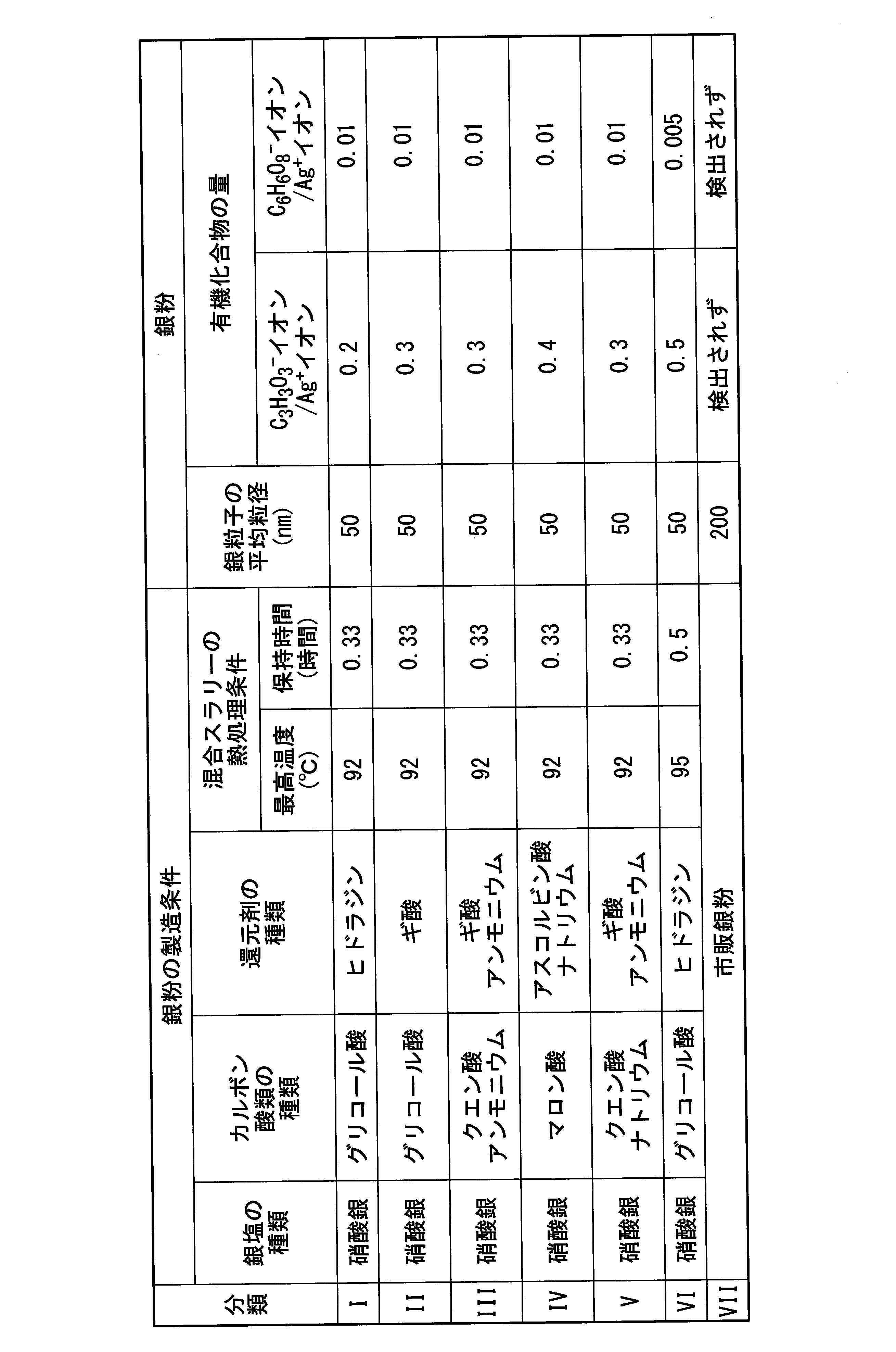
分類I~VIIの銀粉について、銀粒子の平均粒径と、C3H3O3 -イオン/Ag+イオン比と、C6H6O8 -イオン/Ag+イオン比を下記の方法により測定した。その結果を下記の表1に示す。なお、表1には、銀粉の製造に使用した各材料の種類、混合スラリーの熱処理条件(最高温度、保持時間)を併せて記載した。
分類I~VIIの銀粉について、銀粒子の平均粒径と、C3H3O3 -イオン/Ag+イオン比と、C6H6O8 -イオン/Ag+イオン比を下記の方法により測定した。その結果を下記の表1に示す。なお、表1には、銀粉の製造に使用した各材料の種類、混合スラリーの熱処理条件(最高温度、保持時間)を併せて記載した。
(銀粒子の平均粒径)
銀粉をエポキシ樹脂と混合し、得られた混合物を硬化させて銀粒子径の測定用試料を作製した。この銀粒子径の測定用試料の中央部を切断し、その切断面をアルゴンイオンビームにより研磨加工した。研磨加工した加工面を走査型電子顕微鏡(SEM)にて観察し、無作為に1000個以上の銀粒子を選択した。選択した銀粒子について、アルゴンイオンビームの照射方向に沿った方向の直径を粒子径として計測し、その粒子径の平均値を銀粒子の平均粒径とした。
銀粉をエポキシ樹脂と混合し、得られた混合物を硬化させて銀粒子径の測定用試料を作製した。この銀粒子径の測定用試料の中央部を切断し、その切断面をアルゴンイオンビームにより研磨加工した。研磨加工した加工面を走査型電子顕微鏡(SEM)にて観察し、無作為に1000個以上の銀粒子を選択した。選択した銀粒子について、アルゴンイオンビームの照射方向に沿った方向の直径を粒子径として計測し、その粒子径の平均値を銀粒子の平均粒径とした。
(C3H3O3
-イオン/Ag+イオン比とC6H6O8
-イオン/Ag+イオン比)
Ag+イオンとC3H3O3 -イオンとC6H6O8 -イオンの検出量は、飛行時間型二次イオン質量分析法により測定した。銀粉をIn箔表面に埋没したものを測定用試料とした。測定装置はULVAC PHI社製nanoTOFIIを用いた。測定範囲は100μm平方の範囲、一次イオンはBi3 ++(30kV)、測定時間は5分の条件で測定してTOF-SIMSスペクトルを得た。得られたTOF-SIMSスペクトルから、Ag+イオン、C3H3O3 -イオン、C6H6O8 -イオンの検出量を求め、C3H3O3 -イオンとC6H6O8 -イオンの検出量を、それぞれAg+イオンの検出量で除して、C3H3O3 -イオン/Ag+イオン比とC6H6O8 -イオン/Ag+イオン比を算出した。
Ag+イオンとC3H3O3 -イオンとC6H6O8 -イオンの検出量は、飛行時間型二次イオン質量分析法により測定した。銀粉をIn箔表面に埋没したものを測定用試料とした。測定装置はULVAC PHI社製nanoTOFIIを用いた。測定範囲は100μm平方の範囲、一次イオンはBi3 ++(30kV)、測定時間は5分の条件で測定してTOF-SIMSスペクトルを得た。得られたTOF-SIMSスペクトルから、Ag+イオン、C3H3O3 -イオン、C6H6O8 -イオンの検出量を求め、C3H3O3 -イオンとC6H6O8 -イオンの検出量を、それぞれAg+イオンの検出量で除して、C3H3O3 -イオン/Ag+イオン比とC6H6O8 -イオン/Ag+イオン比を算出した。
<本発明例1>
[銀多孔質焼結膜の作製]
銀粉として分類Iの銀粉と、有機溶媒としてエチレングリコールとを、それぞれ配合量が質量部で85:15となるように秤量して、容器に入れた。次いで、この容器を、混練機(THINKY社製、「あわとり練太郎」)を用いて、2000rpmの回転速度で5分間回転させる操作を3回行って、銀粉と有機溶媒とを混練して銀ペーストを調製した(銀ペースト調製工程S01)。
[銀多孔質焼結膜の作製]
銀粉として分類Iの銀粉と、有機溶媒としてエチレングリコールとを、それぞれ配合量が質量部で85:15となるように秤量して、容器に入れた。次いで、この容器を、混練機(THINKY社製、「あわとり練太郎」)を用いて、2000rpmの回転速度で5分間回転させる操作を3回行って、銀粉と有機溶媒とを混練して銀ペーストを調製した(銀ペースト調製工程S01)。
上記の銀ペーストを、ガラス基板上に、2.5mm×2.5mm×厚さ0.05mmのメタルマスク版を用いて印刷して、厚さ0.05mmの銀ペースト膜を形成した(銀ペースト膜形成工程S02)。次いで、銀ペースト膜を形成したガラス基板を送風乾燥機に投入して、加熱温度150℃で加熱時間15分間の焼結条件にて、銀ペースト膜を乾燥させ、銀粒子を部分的に焼結させて銀多孔質焼結膜を生成させた(焼結工程S03)。加熱後、送風乾燥機からガラス基板を取り出し、室温まで放冷した後、ガラス基板から銀多孔質焼結膜を剥がし取って、銀多孔質焼結膜を得た。得られた銀多孔質焼結膜の膜厚は、0.04mmであった。
[接合体の作製]
底面を銀スパッタしたシリコン素子(2.5mm×2.5mm)と、銀めっきを施した銅板(2.5mm×2.5mm)とを用意した。シリコン素子の銀スパッタした底面と、銅板の銀めっきを施した面とを、上記の銀多孔質焼結膜を介して積層して積層体を得た(積層体作製工程S11)。得られた積層体を、加圧ダイボンダを用いて積層方向に10MPaの荷重を付与しながら、大気雰囲気下、室温から30℃/分の速度で200℃まで昇温し、次いで、200℃で15分間加熱した。以上により接合体を得た(加熱工程S12)。得られた接合体は、接合層の膜厚が0.03mmであった。
底面を銀スパッタしたシリコン素子(2.5mm×2.5mm)と、銀めっきを施した銅板(2.5mm×2.5mm)とを用意した。シリコン素子の銀スパッタした底面と、銅板の銀めっきを施した面とを、上記の銀多孔質焼結膜を介して積層して積層体を得た(積層体作製工程S11)。得られた積層体を、加圧ダイボンダを用いて積層方向に10MPaの荷重を付与しながら、大気雰囲気下、室温から30℃/分の速度で200℃まで昇温し、次いで、200℃で15分間加熱した。以上により接合体を得た(加熱工程S12)。得られた接合体は、接合層の膜厚が0.03mmであった。
<本発明例2~8、比較例1~5>
銀ペースト調製工程S01において、銀粉として、下記の表2に示す分類の銀粉を用いたこと以外は、本発明例1と同様にして、銀ペーストを得た。次いで、焼結工程S03において、焼結条件を下記の表2に示す加熱温度および加熱時間としたこと以外は、本発明例1と同様にして、銀多孔質焼結膜を作製した。そして、本発明例1と同様にして、得られた銀多孔質焼結膜を用いて接合体を製造した。ただし、比較例4~5では、銀多孔質焼結膜を作製することができなかったため、接合体を製造することができなかった。なお、本発明例2~8および比較例1~3で得られた接合体は、接合層の膜厚が0.03mmであった。
銀ペースト調製工程S01において、銀粉として、下記の表2に示す分類の銀粉を用いたこと以外は、本発明例1と同様にして、銀ペーストを得た。次いで、焼結工程S03において、焼結条件を下記の表2に示す加熱温度および加熱時間としたこと以外は、本発明例1と同様にして、銀多孔質焼結膜を作製した。そして、本発明例1と同様にして、得られた銀多孔質焼結膜を用いて接合体を製造した。ただし、比較例4~5では、銀多孔質焼結膜を作製することができなかったため、接合体を製造することができなかった。なお、本発明例2~8および比較例1~3で得られた接合体は、接合層の膜厚が0.03mmであった。
<銀多孔質焼結膜と接合体の評価>
本発明例1~8および比較例1~3で得られた銀多孔質焼結膜について、充填率と、結晶子サイズと、C3H7 +イオン/Ag+イオン比と、C2H-イオン/Ag-イオン比を、それぞれ下記の方法により測定した。接合体について、シェア強度を下記の方法により測定した。その結果を下記の表2に示す。
本発明例1~8および比較例1~3で得られた銀多孔質焼結膜について、充填率と、結晶子サイズと、C3H7 +イオン/Ag+イオン比と、C2H-イオン/Ag-イオン比を、それぞれ下記の方法により測定した。接合体について、シェア強度を下記の方法により測定した。その結果を下記の表2に示す。
(充填率)
充填率は、銀多孔質焼結膜の断面画像から求めた。先ず、銀多孔質焼結膜の断面をCP(Cross section Polish)加工した。次いで、その銀多孔質焼結膜の断面を、SEMを用いて1000倍の倍率で撮影した。得られた断面画像を、画像処理ソフト(Image J)を用いて2値化処理した。2値化処理した画像において、白色で表示される銀部分の面積を測定し、視野全体に占める銀部分の面積割合を充填率として算出した。
充填率は、銀多孔質焼結膜の断面画像から求めた。先ず、銀多孔質焼結膜の断面をCP(Cross section Polish)加工した。次いで、その銀多孔質焼結膜の断面を、SEMを用いて1000倍の倍率で撮影した。得られた断面画像を、画像処理ソフト(Image J)を用いて2値化処理した。2値化処理した画像において、白色で表示される銀部分の面積を測定し、視野全体に占める銀部分の面積割合を充填率として算出した。
(結晶子サイズ)
結晶子サイズは、X線回折パターンから求めた。X線回折パターンは、X線回折装置(ブルカー・エイエックスエス社製、D8 ADVANCE)を用いて、下記の測定条件にて測定した。
測定条件
ターゲット:Cu
管電圧:40kV
管電流:40mA
照射X線サイズ:2mmφ以下
走査範囲:30-140deg.
ステップ幅:0.02deg.
結晶子サイズは、X線回折パターンから求めた。X線回折パターンは、X線回折装置(ブルカー・エイエックスエス社製、D8 ADVANCE)を用いて、下記の測定条件にて測定した。
測定条件
ターゲット:Cu
管電圧:40kV
管電流:40mA
照射X線サイズ:2mmφ以下
走査範囲:30-140deg.
ステップ幅:0.02deg.
得られたX線回折パターンを、解析ソフト(ブルカー・エイエックスエス社製、TOPAS:Version5)を用いてPawley法により解析し、ローレンツ関数成分より銀粒子の結晶子サイズを算出した。なお、X線回折パターンの解析に際して、プロファイル関数は、予め測定した標準試料(NIST SRM640d)のX線回折パターンを用いて求めた値に固定した。
(C3H7
+イオン/Ag+イオン比とC2H-イオン/Ag-イオン比)
Ag+イオンとAg-イオンとC3H7 +イオンとC2H-イオンの検出量は、飛行時間型二次イオン質量分析法(TOF-SIMS)より測定した。銀多孔質焼結膜をIn箔表面に埋没したものを測定用試料とした。測定装置および測定条件は、前述のC3H3O3 -イオン/Ag+イオン比とC6H6O8 -イオン/Ag+イオン比の測定方法と同じである。
Ag+イオンとAg-イオンとC3H7 +イオンとC2H-イオンの検出量は、飛行時間型二次イオン質量分析法(TOF-SIMS)より測定した。銀多孔質焼結膜をIn箔表面に埋没したものを測定用試料とした。測定装置および測定条件は、前述のC3H3O3 -イオン/Ag+イオン比とC6H6O8 -イオン/Ag+イオン比の測定方法と同じである。
(シェア強度)
シェア強度は、以下の方法で測定した。銅板とシリコン素子の間に形成された接合層を破断するのに要する力を、ボンディングテスタ(RHESCA社製)により測定した。この測定値を接合面積(シリコン素子の底面の面積)で除してシェア強度とした。なお、接合層を7個作製し、同様の手順で測定を行い、測定値の平均値を接合面積で除してシェア強度とした。
シェア強度は、以下の方法で測定した。銅板とシリコン素子の間に形成された接合層を破断するのに要する力を、ボンディングテスタ(RHESCA社製)により測定した。この測定値を接合面積(シリコン素子の底面の面積)で除してシェア強度とした。なお、接合層を7個作製し、同様の手順で測定を行い、測定値の平均値を接合面積で除してシェア強度とした。
<参考例1>
本発明例1で調製した銀ペーストを、銀めっきを施した銅板(25mm×25mm)の表面に、2.5mm×2.5mm×厚さ0.05mmのメタルマスク版を用いて塗布して、厚さ0.05mmの銀ペースト層を形成した。次いで、この銀ペースト層の上に、底面を銀スパッタしたシリコン素子(2.5mm×2.5mm)の銀スパッタした底面を重ねた。これにより、シリコン素子と銅板の表面とを、上記の銀ペースト層を介して積層した積層体を得た。得られた積層体を、加圧ダイボンダを用いて積層方向に10MPaの荷重を付与しながら、大気雰囲気下、200℃で15分間加熱することにより接合体を得た。得られた接合体は、接合層の膜厚が0.03mmであった。
得られた接合体のシェア強度を上記の方法と同様にして測定した。その結果を、下記の表2に示す。

比較例1の銀多孔質焼結膜では、C3H7
+イオン/Ag+イオン比とC2H-イオン/Ag-イオン比が本実施形態の範囲よりも高かった。この比較例1の銀多孔質焼結膜を用いて製造した接合体は、銀ペーストを用いて製造した参考例1の接合体と比較してシェア強度が低くなった。これは、銀多孔質焼結膜を被覆する有機化合物の量が多いため、銀粒子の焼結性が低下したためであると考えられる。
比較例2の銀多孔質焼結膜では、C3H7
+イオン/Ag+イオン比とC2H-イオン/Ag-イオン比が本実施形態の範囲よりも低かった。この比較例2の銀多孔質焼結膜を用いて製造した接合体は、銀ペーストを用いて製造した参考例1の接合体と比較してシェア強度が低くなった。これは、銀多孔質焼結膜を被覆する有機化合物の量が少ないため、銀多孔質焼結膜を作製してから接合体を製造するまでの間に、銀多孔質焼結膜の表面が硫化して、銀粒子が焼結しにくくなったためであると考えられる。
比較例3の銀多孔質焼結膜では、結晶子サイズが本実施形態の範囲よりも大きく、かつC3H7
+イオン/Ag+イオン比とC2H-イオン/Ag-イオン比が本実施形態の範囲よりも低かった。この比較例3の銀多孔質焼結膜を用いて製造した接合体は、銀ペーストを用いて製造した参考例1の接合体と比較してシェア強度がさらに低くなった。これは、銀多孔質焼結膜の表面が硫化したことに加えて、結晶子サイズが粗大であるため、銀粒子の焼結性が大きく低下したためであると考えられる。
比較例4では、銀ペースト膜の加熱温度を80℃としたが、加熱温度が低くなりすぎて、銀粒子が部分的にしか焼結せず、結晶子サイズも小さく、有機化合物の量も多かった。そのため、自立した銀多孔質焼結膜が得られなかった。よって、銀の結晶子サイズと有機化合物の量以外の測定は行わなかった。
また、比較例5では、銀粒子の平均粒径が200nmの銀粉を用いたが、銀粒子の焼結性が低く、加熱温度が150℃では銀粒子の焼結が進まず、自立した銀多孔質焼結膜が得られなかった。また、銀の結晶子サイズも大きくなった。よって、銀の結晶子サイズと有機化合物の量以外の測定は行わなかった。
また、比較例5では、銀粒子の平均粒径が200nmの銀粉を用いたが、銀粒子の焼結性が低く、加熱温度が150℃では銀粒子の焼結が進まず、自立した銀多孔質焼結膜が得られなかった。また、銀の結晶子サイズも大きくなった。よって、銀の結晶子サイズと有機化合物の量以外の測定は行わなかった。
これに対して、結晶子サイズが本実施形態の範囲にあり、C3H7
+イオン/Ag+イオン比とC2H-イオン/Ag-イオン比が本実施形態の範囲にある本発明例1~8の銀多孔質焼結膜を用いて製造した接合体は、銀ペーストを用いて製造した参考例1の接合体と比較してシェア強度が高くなることが確認された。これは、本発明例1~8の銀多孔質焼結膜は、接合体製造時の加熱の際に有機溶媒が揮発しないので、内部に気孔が生成しにくく、緻密な接合層を形成するためであると考えられる。
なお、例えばシェア強度の測定値が65MPaであるときには、シェア強度の測定値には-5MPa~+5MPa程度のばらつきが生じる。このため、本発明例1,5,6のシェア強度60MPaと、本発明例4のシェア強度70MPaはほぼ同じ値であるといえる。
本発明例2,3では、有機化合物の量が異なるが、シェア強度が同じであった。これは、本発明例2,3では、焼結性に著しい差異が生じなかったためであると推測される。
なお、例えばシェア強度の測定値が65MPaであるときには、シェア強度の測定値には-5MPa~+5MPa程度のばらつきが生じる。このため、本発明例1,5,6のシェア強度60MPaと、本発明例4のシェア強度70MPaはほぼ同じ値であるといえる。
本発明例2,3では、有機化合物の量が異なるが、シェア強度が同じであった。これは、本発明例2,3では、焼結性に著しい差異が生じなかったためであると推測される。
本発明例1で作製した銀多孔質焼結膜を樹脂埋めした状態で、断面を研磨して、銀多孔質焼結膜の断面を露出させた。その断面を、SEMを用いて観察した。図4に、銀多孔質焼結膜の断面のSEM写真を示す。また、本発明例1で作製した銀多孔質焼結膜を用いて製造した接合体を樹脂埋めした状態で、断面を研磨して、接合層の断面を露出させた。その断面を、SEMを用いて観察した。図5に、接合層の断面のSEM写真を示す。
図4の銀多孔質焼結膜のSEM写真から、銀多孔質焼結膜は銀粒子が部分的に焼結し、部分的に焼結した銀粒子間に連続気孔が形成された構造であることが確認された。また、図5の接合層のSEM写真から、銀多孔質焼結膜は加熱によって銀粒子の焼結がさらに進み、緻密な銀粒子焼結体(接合層)を形成することが確認された。
本実施形態の銀多孔質焼結膜によれば、比較的低温度の加熱によって、緻密で接合強度が高い銀粒子焼結体(接合層)を有する接合体を製造できる。このため、本実施形態の銀多孔質焼結膜は、LED(発光ダイオード)素子やパワー半導体チップなどの電子部品の組立てや実装等の工程のうち、2つ以上の部品を接合して接合体を製造する工程に好適に用いることができる。
11 接合体
12 第1部材
13 接合層
14 第2部材
12 第1部材
13 接合層
14 第2部材
Claims (2)
- 銀粒子を焼結させてなる銀多孔質焼結膜であって、
結晶子サイズが60nm以上150nm以下の範囲内にあり、飛行時間型二次イオン質量分析法によって測定されるAg+イオンの検出量に対するC3H7 +イオンの検出量の比が0.10以上0.35以下の範囲内にあって、かつ飛行時間型二次イオン質量分析法によって測定されるAg-イオンの検出量に対するC2H-イオンの検出量の比が0.9以上3.7以下の範囲内にあることを特徴とする銀多孔質焼結膜。 - 第1部材と第2部材とが接合された接合体の製造方法であって、
前記第1部材と前記第2部材とを、請求項1に記載の銀多孔質焼結膜を介して積層して積層体を得る工程と、
前記積層体を加熱する工程と、
を有することを特徴とする接合体の製造方法。
Priority Applications (4)
| Application Number | Priority Date | Filing Date | Title |
|---|---|---|---|
| CN201980009215.0A CN111629850A (zh) | 2018-03-28 | 2019-03-22 | 银多孔烧结膜及接合体的制造方法 |
| KR1020207022601A KR20200131811A (ko) | 2018-03-28 | 2019-03-22 | 은 다공질 소결막 및 접합체의 제조 방법 |
| US16/965,710 US20200376545A1 (en) | 2018-03-28 | 2019-03-22 | Sintered porous silver film and production method for joint body |
| EP19777787.3A EP3778075A4 (en) | 2018-03-28 | 2019-03-22 | Sintered porous silver film and production method for joint body |
Applications Claiming Priority (4)
| Application Number | Priority Date | Filing Date | Title |
|---|---|---|---|
| JP2018-061321 | 2018-03-28 | ||
| JP2018061321 | 2018-03-28 | ||
| JP2019-050381 | 2019-03-18 | ||
| JP2019050381A JP7120096B2 (ja) | 2018-03-28 | 2019-03-18 | 銀多孔質焼結膜および接合体の製造方法 |
Publications (1)
| Publication Number | Publication Date |
|---|---|
| WO2019188793A1 true WO2019188793A1 (ja) | 2019-10-03 |
Family
ID=68061783
Family Applications (1)
| Application Number | Title | Priority Date | Filing Date |
|---|---|---|---|
| PCT/JP2019/012119 Ceased WO2019188793A1 (ja) | 2018-03-28 | 2019-03-22 | 銀多孔質焼結膜および接合体の製造方法 |
Country Status (1)
| Country | Link |
|---|---|
| WO (1) | WO2019188793A1 (ja) |
Cited By (1)
| Publication number | Priority date | Publication date | Assignee | Title |
|---|---|---|---|---|
| CN111472077A (zh) * | 2020-04-20 | 2020-07-31 | 深圳千维生态纺织有限公司 | 一种功能性抗病毒的纺织品面料及其制备方法和应用 |
Citations (5)
| Publication number | Priority date | Publication date | Assignee | Title |
|---|---|---|---|---|
| JP2012224885A (ja) * | 2011-04-15 | 2012-11-15 | Nippon Steel Chem Co Ltd | 金属多孔質体の製造方法 |
| JP2016169411A (ja) | 2015-03-12 | 2016-09-23 | 日立化成株式会社 | 多孔質銀製シート及び多孔質銀製シートを用いた金属製部材接合体 |
| JP2017111975A (ja) | 2015-12-16 | 2017-06-22 | 三菱マテリアル株式会社 | 接合材及び接合体の製造方法 |
| JP2018061321A (ja) | 2016-10-03 | 2018-04-12 | 住友電装株式会社 | 車載用の電気接続箱 |
| JP2019050381A (ja) | 2018-09-28 | 2019-03-28 | 大日本印刷株式会社 | 太陽電池モジュール用の封止材組成物、及び、太陽電池モジュール用の封止材シートの製造方法 |
-
2019
- 2019-03-22 WO PCT/JP2019/012119 patent/WO2019188793A1/ja not_active Ceased
Patent Citations (5)
| Publication number | Priority date | Publication date | Assignee | Title |
|---|---|---|---|---|
| JP2012224885A (ja) * | 2011-04-15 | 2012-11-15 | Nippon Steel Chem Co Ltd | 金属多孔質体の製造方法 |
| JP2016169411A (ja) | 2015-03-12 | 2016-09-23 | 日立化成株式会社 | 多孔質銀製シート及び多孔質銀製シートを用いた金属製部材接合体 |
| JP2017111975A (ja) | 2015-12-16 | 2017-06-22 | 三菱マテリアル株式会社 | 接合材及び接合体の製造方法 |
| JP2018061321A (ja) | 2016-10-03 | 2018-04-12 | 住友電装株式会社 | 車載用の電気接続箱 |
| JP2019050381A (ja) | 2018-09-28 | 2019-03-28 | 大日本印刷株式会社 | 太陽電池モジュール用の封止材組成物、及び、太陽電池モジュール用の封止材シートの製造方法 |
Non-Patent Citations (1)
| Title |
|---|
| See also references of EP3778075A4 |
Cited By (2)
| Publication number | Priority date | Publication date | Assignee | Title |
|---|---|---|---|---|
| CN111472077A (zh) * | 2020-04-20 | 2020-07-31 | 深圳千维生态纺织有限公司 | 一种功能性抗病毒的纺织品面料及其制备方法和应用 |
| CN111472077B (zh) * | 2020-04-20 | 2021-05-25 | 深圳千维生态纺织有限公司 | 一种功能性抗病毒的纺织品面料及其制备方法和应用 |
Similar Documents
| Publication | Publication Date | Title |
|---|---|---|
| JP7120096B2 (ja) | 銀多孔質焼結膜および接合体の製造方法 | |
| EP3348338B1 (en) | Copper paste for joining, method for producing joined body, and method for producing semiconductor device | |
| JP6337909B2 (ja) | 電子部品モジュールの製造方法 | |
| TWI819113B (zh) | 接合材料用粒子及其製造方法、接合用糊料及其調製方法以及接合體之製造方法 | |
| JP7476261B2 (ja) | 焼結ダイアタッチ及び類似した用途のためのナノ銅ペースト及びフィルム | |
| CN102893388B (zh) | 电子部件及其制造方法 | |
| TWI892998B (zh) | 低溫燒結性接合用膏、低溫燒結性接合用膏製造用材料及其製造方法、以及接合結構體 | |
| JP7380256B2 (ja) | 接合用シート | |
| WO2007083811A1 (ja) | 導体ペースト、多層セラミック基板及び多層セラミック基板の製造方法 | |
| CN108605417A (zh) | 陶瓷基板及其制造方法 | |
| JP6531547B2 (ja) | 接合材及び接合体の製造方法 | |
| CN114829042B (zh) | 银膏及其制造方法以及接合体的制造方法 | |
| CN114829036B (zh) | 银膏及接合体的制造方法 | |
| TW202006749A (zh) | 導電性膠及燒結體 | |
| CN113168931B (zh) | 导电性糊料、层叠体及Cu基板或Cu电极与导电体的接合方法 | |
| WO2019188793A1 (ja) | 銀多孔質焼結膜および接合体の製造方法 | |
| JP6565527B2 (ja) | Ag下地層付パワーモジュール用基板及びパワーモジュール | |
| CN116806177B (zh) | 接合用浆料、接合层、接合体及接合体的制造方法 | |
| KR102380037B1 (ko) | Ag 하지층이 형성된 파워 모듈용 기판 및 파워 모듈 | |
| WO2020071432A1 (ja) | 接合材料用粒子及びその製造方法、接合用ペースト及びその調製方法並びに接合体の製造方法 | |
| JP6859799B2 (ja) | ペースト状銀粉組成物、接合体の製造方法および銀膜の製造方法 | |
| CN118215549A (zh) | 铜微粒子分散体 | |
| JP6853437B2 (ja) | 銀粉、銀粉の製造方法、ペースト状組成物、接合体の製造方法および銀膜の製造方法 | |
| JP7589567B2 (ja) | 接合用シート | |
| KR20200127165A (ko) | 금속 입자 응집체 및 그 제조 방법 그리고 페이스트상 금속 입자 응집체 조성물 및 이것을 사용한 접합체의 제조 방법 |
Legal Events
| Date | Code | Title | Description |
|---|---|---|---|
| 121 | Ep: the epo has been informed by wipo that ep was designated in this application |
Ref document number: 19777787 Country of ref document: EP Kind code of ref document: A1 |
|
| NENP | Non-entry into the national phase |
Ref country code: DE |
|
| ENP | Entry into the national phase |
Ref document number: 2019777787 Country of ref document: EP Effective date: 20201028 |
|
| WWW | Wipo information: withdrawn in national office |
Ref document number: 2019777787 Country of ref document: EP |