WO2019188935A1 - マイクロニードルアレイの製造方法 - Google Patents
マイクロニードルアレイの製造方法 Download PDFInfo
- Publication number
- WO2019188935A1 WO2019188935A1 PCT/JP2019/012412 JP2019012412W WO2019188935A1 WO 2019188935 A1 WO2019188935 A1 WO 2019188935A1 JP 2019012412 W JP2019012412 W JP 2019012412W WO 2019188935 A1 WO2019188935 A1 WO 2019188935A1
- Authority
- WO
- WIPO (PCT)
- Prior art keywords
- needle
- mold
- drug solution
- recess
- manufacturing
- Prior art date
- Legal status (The legal status is an assumption and is not a legal conclusion. Google has not performed a legal analysis and makes no representation as to the accuracy of the status listed.)
- Ceased
Links
Images


Classifications
-
- A—HUMAN NECESSITIES
- A61—MEDICAL OR VETERINARY SCIENCE; HYGIENE
- A61M—DEVICES FOR INTRODUCING MEDIA INTO, OR ONTO, THE BODY; DEVICES FOR TRANSDUCING BODY MEDIA OR FOR TAKING MEDIA FROM THE BODY; DEVICES FOR PRODUCING OR ENDING SLEEP OR STUPOR
- A61M37/00—Other apparatus for introducing media into the body; Percutany, i.e. introducing medicines into the body by diffusion through the skin
- A61M37/0015—Other apparatus for introducing media into the body; Percutany, i.e. introducing medicines into the body by diffusion through the skin by using microneedles
-
- B—PERFORMING OPERATIONS; TRANSPORTING
- B29—WORKING OF PLASTICS; WORKING OF SUBSTANCES IN A PLASTIC STATE IN GENERAL
- B29C—SHAPING OR JOINING OF PLASTICS; SHAPING OF MATERIAL IN A PLASTIC STATE, NOT OTHERWISE PROVIDED FOR; AFTER-TREATMENT OF THE SHAPED PRODUCTS, e.g. REPAIRING
- B29C33/00—Moulds or cores; Details thereof or accessories therefor
- B29C33/38—Moulds or cores; Details thereof or accessories therefor characterised by the material or the manufacturing process
- B29C33/3842—Manufacturing moulds, e.g. shaping the mould surface by machining
- B29C33/3857—Manufacturing moulds, e.g. shaping the mould surface by machining by making impressions of one or more parts of models, e.g. shaped articles and including possible subsequent assembly of the parts
-
- B—PERFORMING OPERATIONS; TRANSPORTING
- B29—WORKING OF PLASTICS; WORKING OF SUBSTANCES IN A PLASTIC STATE IN GENERAL
- B29C—SHAPING OR JOINING OF PLASTICS; SHAPING OF MATERIAL IN A PLASTIC STATE, NOT OTHERWISE PROVIDED FOR; AFTER-TREATMENT OF THE SHAPED PRODUCTS, e.g. REPAIRING
- B29C33/00—Moulds or cores; Details thereof or accessories therefor
- B29C33/38—Moulds or cores; Details thereof or accessories therefor characterised by the material or the manufacturing process
- B29C33/40—Plastics, e.g. foam or rubber
-
- B—PERFORMING OPERATIONS; TRANSPORTING
- B29—WORKING OF PLASTICS; WORKING OF SUBSTANCES IN A PLASTIC STATE IN GENERAL
- B29C—SHAPING OR JOINING OF PLASTICS; SHAPING OF MATERIAL IN A PLASTIC STATE, NOT OTHERWISE PROVIDED FOR; AFTER-TREATMENT OF THE SHAPED PRODUCTS, e.g. REPAIRING
- B29C39/00—Shaping by casting, i.e. introducing the moulding material into a mould or between confining surfaces without significant moulding pressure; Apparatus therefor
- B29C39/22—Component parts, details or accessories; Auxiliary operations
- B29C39/24—Feeding the material into the mould
-
- B—PERFORMING OPERATIONS; TRANSPORTING
- B29—WORKING OF PLASTICS; WORKING OF SUBSTANCES IN A PLASTIC STATE IN GENERAL
- B29C—SHAPING OR JOINING OF PLASTICS; SHAPING OF MATERIAL IN A PLASTIC STATE, NOT OTHERWISE PROVIDED FOR; AFTER-TREATMENT OF THE SHAPED PRODUCTS, e.g. REPAIRING
- B29C39/00—Shaping by casting, i.e. introducing the moulding material into a mould or between confining surfaces without significant moulding pressure; Apparatus therefor
- B29C39/22—Component parts, details or accessories; Auxiliary operations
- B29C39/42—Casting under special conditions, e.g. vacuum
-
- B—PERFORMING OPERATIONS; TRANSPORTING
- B29—WORKING OF PLASTICS; WORKING OF SUBSTANCES IN A PLASTIC STATE IN GENERAL
- B29C—SHAPING OR JOINING OF PLASTICS; SHAPING OF MATERIAL IN A PLASTIC STATE, NOT OTHERWISE PROVIDED FOR; AFTER-TREATMENT OF THE SHAPED PRODUCTS, e.g. REPAIRING
- B29C39/00—Shaping by casting, i.e. introducing the moulding material into a mould or between confining surfaces without significant moulding pressure; Apparatus therefor
- B29C39/22—Component parts, details or accessories; Auxiliary operations
- B29C39/44—Measuring, controlling or regulating
-
- B—PERFORMING OPERATIONS; TRANSPORTING
- B29—WORKING OF PLASTICS; WORKING OF SUBSTANCES IN A PLASTIC STATE IN GENERAL
- B29C—SHAPING OR JOINING OF PLASTICS; SHAPING OF MATERIAL IN A PLASTIC STATE, NOT OTHERWISE PROVIDED FOR; AFTER-TREATMENT OF THE SHAPED PRODUCTS, e.g. REPAIRING
- B29C45/00—Injection moulding, i.e. forcing the required volume of moulding material through a nozzle into a closed mould; Apparatus therefor
- B29C45/17—Component parts, details or accessories; Auxiliary operations
- B29C45/26—Moulds
- B29C45/2673—Moulds with exchangeable mould parts, e.g. cassette moulds
- B29C45/2675—Mounting of exchangeable mould inserts
-
- A—HUMAN NECESSITIES
- A61—MEDICAL OR VETERINARY SCIENCE; HYGIENE
- A61M—DEVICES FOR INTRODUCING MEDIA INTO, OR ONTO, THE BODY; DEVICES FOR TRANSDUCING BODY MEDIA OR FOR TAKING MEDIA FROM THE BODY; DEVICES FOR PRODUCING OR ENDING SLEEP OR STUPOR
- A61M37/00—Other apparatus for introducing media into the body; Percutany, i.e. introducing medicines into the body by diffusion through the skin
- A61M37/0015—Other apparatus for introducing media into the body; Percutany, i.e. introducing medicines into the body by diffusion through the skin by using microneedles
- A61M2037/0023—Drug applicators using microneedles
-
- A—HUMAN NECESSITIES
- A61—MEDICAL OR VETERINARY SCIENCE; HYGIENE
- A61M—DEVICES FOR INTRODUCING MEDIA INTO, OR ONTO, THE BODY; DEVICES FOR TRANSDUCING BODY MEDIA OR FOR TAKING MEDIA FROM THE BODY; DEVICES FOR PRODUCING OR ENDING SLEEP OR STUPOR
- A61M37/00—Other apparatus for introducing media into the body; Percutany, i.e. introducing medicines into the body by diffusion through the skin
- A61M37/0015—Other apparatus for introducing media into the body; Percutany, i.e. introducing medicines into the body by diffusion through the skin by using microneedles
- A61M2037/003—Other apparatus for introducing media into the body; Percutany, i.e. introducing medicines into the body by diffusion through the skin by using microneedles having a lumen
-
- A—HUMAN NECESSITIES
- A61—MEDICAL OR VETERINARY SCIENCE; HYGIENE
- A61M—DEVICES FOR INTRODUCING MEDIA INTO, OR ONTO, THE BODY; DEVICES FOR TRANSDUCING BODY MEDIA OR FOR TAKING MEDIA FROM THE BODY; DEVICES FOR PRODUCING OR ENDING SLEEP OR STUPOR
- A61M37/00—Other apparatus for introducing media into the body; Percutany, i.e. introducing medicines into the body by diffusion through the skin
- A61M37/0015—Other apparatus for introducing media into the body; Percutany, i.e. introducing medicines into the body by diffusion through the skin by using microneedles
- A61M2037/0046—Solid microneedles
-
- A—HUMAN NECESSITIES
- A61—MEDICAL OR VETERINARY SCIENCE; HYGIENE
- A61M—DEVICES FOR INTRODUCING MEDIA INTO, OR ONTO, THE BODY; DEVICES FOR TRANSDUCING BODY MEDIA OR FOR TAKING MEDIA FROM THE BODY; DEVICES FOR PRODUCING OR ENDING SLEEP OR STUPOR
- A61M37/00—Other apparatus for introducing media into the body; Percutany, i.e. introducing medicines into the body by diffusion through the skin
- A61M37/0015—Other apparatus for introducing media into the body; Percutany, i.e. introducing medicines into the body by diffusion through the skin by using microneedles
- A61M2037/0053—Methods for producing microneedles
-
- B—PERFORMING OPERATIONS; TRANSPORTING
- B29—WORKING OF PLASTICS; WORKING OF SUBSTANCES IN A PLASTIC STATE IN GENERAL
- B29C—SHAPING OR JOINING OF PLASTICS; SHAPING OF MATERIAL IN A PLASTIC STATE, NOT OTHERWISE PROVIDED FOR; AFTER-TREATMENT OF THE SHAPED PRODUCTS, e.g. REPAIRING
- B29C41/00—Shaping by coating a mould, core or other substrate, i.e. by depositing material and stripping-off the shaped article; Apparatus therefor
- B29C41/02—Shaping by coating a mould, core or other substrate, i.e. by depositing material and stripping-off the shaped article; Apparatus therefor for making articles of definite length, i.e. discrete articles
- B29C41/04—Rotational or centrifugal casting, i.e. coating the inside of a mould by rotating the mould
- B29C41/042—Rotational or centrifugal casting, i.e. coating the inside of a mould by rotating the mould by rotating a mould around its axis of symmetry
- B29C41/045—Rotational or centrifugal casting, i.e. coating the inside of a mould by rotating the mould by rotating a mould around its axis of symmetry the axis being placed vertically, e.g. spin casting
-
- B—PERFORMING OPERATIONS; TRANSPORTING
- B29—WORKING OF PLASTICS; WORKING OF SUBSTANCES IN A PLASTIC STATE IN GENERAL
- B29K—INDEXING SCHEME ASSOCIATED WITH SUBCLASSES B29B, B29C OR B29D, RELATING TO MOULDING MATERIALS OR TO MATERIALS FOR MOULDS, REINFORCEMENTS, FILLERS OR PREFORMED PARTS, e.g. INSERTS
- B29K2003/00—Use of starch or derivatives as moulding material
-
- B—PERFORMING OPERATIONS; TRANSPORTING
- B29—WORKING OF PLASTICS; WORKING OF SUBSTANCES IN A PLASTIC STATE IN GENERAL
- B29K—INDEXING SCHEME ASSOCIATED WITH SUBCLASSES B29B, B29C OR B29D, RELATING TO MOULDING MATERIALS OR TO MATERIALS FOR MOULDS, REINFORCEMENTS, FILLERS OR PREFORMED PARTS, e.g. INSERTS
- B29K2005/00—Use of polysaccharides or derivatives as moulding material
-
- B—PERFORMING OPERATIONS; TRANSPORTING
- B29—WORKING OF PLASTICS; WORKING OF SUBSTANCES IN A PLASTIC STATE IN GENERAL
- B29K—INDEXING SCHEME ASSOCIATED WITH SUBCLASSES B29B, B29C OR B29D, RELATING TO MOULDING MATERIALS OR TO MATERIALS FOR MOULDS, REINFORCEMENTS, FILLERS OR PREFORMED PARTS, e.g. INSERTS
- B29K2883/00—Use of polymers having silicon, with or without sulfur, nitrogen, oxygen, or carbon only, in the main chain, as mould material
-
- B—PERFORMING OPERATIONS; TRANSPORTING
- B29—WORKING OF PLASTICS; WORKING OF SUBSTANCES IN A PLASTIC STATE IN GENERAL
- B29K—INDEXING SCHEME ASSOCIATED WITH SUBCLASSES B29B, B29C OR B29D, RELATING TO MOULDING MATERIALS OR TO MATERIALS FOR MOULDS, REINFORCEMENTS, FILLERS OR PREFORMED PARTS, e.g. INSERTS
- B29K2901/00—Use of unspecified macromolecular compounds as mould material
- B29K2901/10—Thermosetting resins
-
- B—PERFORMING OPERATIONS; TRANSPORTING
- B29—WORKING OF PLASTICS; WORKING OF SUBSTANCES IN A PLASTIC STATE IN GENERAL
- B29K—INDEXING SCHEME ASSOCIATED WITH SUBCLASSES B29B, B29C OR B29D, RELATING TO MOULDING MATERIALS OR TO MATERIALS FOR MOULDS, REINFORCEMENTS, FILLERS OR PREFORMED PARTS, e.g. INSERTS
- B29K2995/00—Properties of moulding materials, reinforcements, fillers, preformed parts or moulds
- B29K2995/0037—Other properties
- B29K2995/0059—Degradable
- B29K2995/0062—Degradable water-soluble
-
- B—PERFORMING OPERATIONS; TRANSPORTING
- B29—WORKING OF PLASTICS; WORKING OF SUBSTANCES IN A PLASTIC STATE IN GENERAL
- B29L—INDEXING SCHEME ASSOCIATED WITH SUBCLASS B29C, RELATING TO PARTICULAR ARTICLES
- B29L2031/00—Other particular articles
- B29L2031/753—Medical equipment; Accessories therefor
- B29L2031/7544—Injection needles, syringes
-
- B—PERFORMING OPERATIONS; TRANSPORTING
- B29—WORKING OF PLASTICS; WORKING OF SUBSTANCES IN A PLASTIC STATE IN GENERAL
- B29L—INDEXING SCHEME ASSOCIATED WITH SUBCLASS B29C, RELATING TO PARTICULAR ARTICLES
- B29L2031/00—Other particular articles
- B29L2031/756—Microarticles, nanoarticles
Definitions
- the present invention relates to a method of manufacturing a microneedle array, and more particularly to a method of manufacturing a microneedle array in which a drug solution is discharged from a drug solution discharge nozzle into a needle-like recess of a mold.
- microneedle array percutaneous absorption sheet
- needle-like convex portions also referred to as microneedles or microneedles
- the drug on the needle-like convex portion is delivered into the skin.
- a mold having a needle-like concave portion also referred to as a needle hole portion
- a solution containing a drug in the needle hole portion also referred to as a drug solution.
- a solution containing a needle also referred to as a needle raw material is applied and dried to form microneedles.
- the filling amount is related to the drug dose, it is necessary to reliably fill a very small amount of the drug solution with a certain amount with high accuracy for each mold sheet.
- Patent Documents 1 and 2 have a problem that the drug solution cannot be accurately filled into the needle-like recesses of the mold.
- Patent Documents 3 and 4 a filling method is used in which droplets are ejected into the needle-like recesses of the mold.
- filling is performed at a high speed to increase productivity, the landing positions of the droplets and the needle-like recesses of the mold There was a problem that the position of was shifted.
- the drug solution cannot fill the tip of the needle-shaped recess.
- the production yield of the microneedle array is reduced.
- the present invention has been made in view of such circumstances, and an object of the present invention is to provide a method of manufacturing a microneedle array that reliably fills the tip of a needle-like recess with a drug solution.
- one aspect of a method of manufacturing a microneedle array includes a positioning adjustment step of positioning and adjusting a mold having a needle-like recess on a surface and a drug solution discharge nozzle that discharges a drug solution in a first direction; A relative movement step of relatively moving the mold and the drug solution discharge nozzle so as to match the position of the needle-like recess and the position of the drug solution discharge nozzle in plan view in the first direction; and the needle-like recess from the drug solution discharge nozzle
- a method for manufacturing a microneedle array comprising: a discharge step of discharging a drug solution toward the surface; and a suction step of sucking the back surface of the mold.
- the discharged drug solution can be landed on the needle-shaped recess and filled at the tip of the needle-shaped recess.
- the position of the needle-shaped recess and the position of the drug solution discharge nozzle need only be matched so that the drug solution discharged from the drug solution discharge nozzle toward the needle-shaped recess reaches the needle-shaped recess. Strictly, the positions of the two do not have to match.
- the needle-shaped recess has an opening diameter of 600 ⁇ m or more, an angle formed with the flat portion of the mold is 30.0 degrees or more, and the discharge amount of the drug solution discharged to one needle-shaped recess is 30 nL or more. It is preferable.
- the opening diameter 600 ⁇ m or more it becomes easy for the discharged drug solution to land on the needle-shaped recess, and by setting the angle formed with the flat portion of the mold to 30.0 degrees or more, the landed drug solution can be applied to the needle-shaped recess. It can be easily collected or poured into the center, and the needle-like recess can be easily closed by setting the discharge amount of the drug solution to 30 nL or more. As a result, the discharged drug solution can be landed on the needle-shaped recess and filled at the tip of the needle-shaped recess.
- the opening diameter of the needle-like recess is preferably 1200 ⁇ m or less. Thereby, the discharged chemical liquid can be landed on the needle-like recess.
- the angle of the needle-like recess is preferably 90.0 degrees or less. As a result, the landed drug solution can be easily collected or poured into the center of the needle-shaped recess.
- the discharge amount is preferably 150 nL or less. Thereby, a needle-like recessed part can be obstruct
- the first edge portion of the opening of the needle-like recess is chamfered, and the first radius of curvature of the chamfer of the first edge portion is preferably 30 ⁇ m or more.
- the first radius of curvature is preferably 300 ⁇ m or less.
- the needle-like concave portion includes a cup portion provided on the surface of the mold, and a tip concave portion connected to the cup portion and having a tapered shape in the depth direction of the mold, and a second edge portion between the cup portion and the tip concave portion. Is chamfered, and the second radius of curvature of the chamfer of the second edge portion is preferably 30 ⁇ m or more. This prevents the drug solution landed on the needle-shaped recess from being pinned to the second edge portion, so that the drug solution can be easily collected or poured into the center of the needle-shaped recess, Can be filled.
- the second radius of curvature is preferably 300 ⁇ m or less. This prevents the drug solution discharged to the needle-shaped recess from being pinned to the second edge portion, so that the drug solution can be easily collected or poured into the center of the needle-shaped recess and fills the tip of the needle-shaped recess. can do.
- the flying speed of the chemical liquid discharged from the chemical liquid discharge nozzle is 0.2 m / s or more. Thereby, the discharged drug solution can be easily collected or poured into the center of the needle-like recess.
- the flying speed of the chemical liquid discharged from the chemical liquid discharge nozzle is 1.0 m / s or less. Thereby, the discharged drug solution can be easily collected or poured into the center of the needle-like recess.
- a photographing step of photographing a plurality of positions of the mold wherein the positioning adjustment step calculates a position of the needle-like recess based on the plurality of photographed positions, and the relative movement step calculates the position of the needle-like recess based on the calculated result. It is preferable that the position matches the landing position of the chemical liquid discharged from the chemical liquid discharge nozzle. Thereby, the discharged chemical liquid can be appropriately landed on the needle-like recess.
- the mold has a plurality of needle-like recesses, and the suction step preferably sucks the back surface of the mold after the drug solution is discharged to all the needle-like recesses of the plurality of needle-like recesses. Thereby, the chemical
- the mold has gas permeability. Therefore, since it can attract
- medical solution can be manufactured.
- the drug solution preferably contains at least one of a drug stock solution, a saccharide, and an additive. Thereby, the microneedle array according to a use can be manufactured.
- the tip of the needle-like recess can be reliably filled with the drug solution.
- FIG. 3 is a partially enlarged view of a section 3-3 in FIG. 2.
- FIG. 1 is a perspective view showing an example of a transdermal absorption sheet 100.
- the transdermal absorption sheet 100 has a front surface 100 ⁇ / b> A and a back surface 100 ⁇ / b> B, and includes a sheet-like sheet portion 102 and a convex pattern 110.
- the sheet shape means a flat shape as a whole with a small thickness with respect to two opposing front and back surfaces 100A and 100B having a large area, and the front and back surfaces 100A and 100B do not have to be completely flat.
- 1 is circular in a plan view, but may be rectangular, polygonal, elliptical, or the like.
- the convex pattern 110 has a plurality of needle-like convex portions 112.
- the needle-like convex portion 112 is provided on the surface 100A.
- the needle-like convex part 112 includes a needle part 114 and a frustum part 116 that connects the needle part 114 and the seat part 102.
- a plurality of frustum portions 116 are formed on the surface 100 ⁇ / b> A of the transdermal absorption sheet 100.
- the frustum portion 116 has two bottom surfaces and has a three-dimensional structure surrounded by a cone surface. Of the two bottom surfaces of the frustum portion 116, the bottom surface (lower bottom surface) having a large area is connected to the sheet portion 102. Of the two bottom surfaces of the frustum portion 116, the bottom surface (upper bottom surface) having a small area is connected to the needle portion 114. That is, of the two bottom surfaces of the frustum portion 116, the area of the bottom surface in the direction away from the sheet portion 102 is small.
- the needle part 114 has a shape with a bottom surface having a wide area and a tip having a narrowest area away from the bottom surface. Since the bottom surface having a large area of the needle part 114 is connected to the upper bottom surface of the frustum part 116, the needle part 114 is tapered in a direction away from the frustum part 116. Therefore, the needle-like convex part 112 constituted by the needle part 114 and the frustum part 116 has a tapered shape from the sheet part 102 toward the tip as a whole. On the sheet portion 102, 4 to 2500 plural needle-like convex portions 112 are provided. However, it is not limited to this number.
- the frustum portion 116 has a truncated cone shape
- the needle portion 114 has a cone shape.
- the shape of the tip of the needle part 114 can be appropriately changed to a curved surface with a radius of curvature of 0.01 ⁇ m or more and 50 ⁇ m or less, or a flat surface.
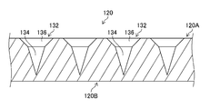
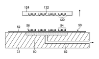
- FIG. 2 is a perspective view showing an example of a mold 120 (mold for manufacturing a transdermal absorption sheet) for manufacturing the transdermal absorption sheet 100.
- FIG. 3 is a partially enlarged view of a section 3-3 in FIG.
- the mold 120 has a front surface 120A and a back surface 120B, and is composed of a flat portion 122 and a concave pattern 130.
- the flat part 122 has a flat shape corresponding to the sheet part 102 of the transdermal absorption sheet 100.
- the concave pattern 130 includes a plurality of needle-shaped concave portions 132.
- the needle-shaped concave portion 132 has a shape corresponding to the needle-shaped convex portion 112 of the transdermal absorption sheet 100, and includes a tip concave portion 134 corresponding to the needle portion 114 and a cup portion 136 corresponding to the frustum portion 116. Composed.
- the tip recess 134 has a tapered shape in the depth direction of the mold 120.
- the tip recess 134 can have a diameter of 150 ⁇ m to 500 ⁇ m and a height of 150 ⁇ m to 2000 ⁇ m.
- the cup 136 has an opening in the surface 120A of the mold 120, has a shape that becomes narrower in the depth direction of the mold 120, and is connected to the tip recess 134 at the narrowest portion.
- the cup portion 136 can have a diameter of 500 ⁇ m to 1000 ⁇ m and a height of 100 ⁇ m to 500 ⁇ m.
- the shape of the needle-like recess 132 is not limited to this example. It is good also as a rocket type which provided the intermediate
- FIG. Further, a through hole that reaches the back surface 120B and penetrates the mold 120 may be formed at the tip of the tapered shape. What is necessary is just to determine the arrangement
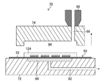
- a mold 70 including a first mold 72 and a second mold 74 is prepared.
- a cavity 76 is formed in the mold 70 by clamping the first mold 72 and the second mold 74.
- the cavity 76 means a space filled with resin.
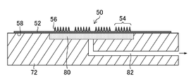
- an electroforming mold 50 is prepared.
- a convex pattern 54 which is a reverse shape of a mold to be produced is formed.
- the convex pattern 54 is a state in which a plurality of needle-like convex portions 56 are arranged in an array.
- the needle-like convex part 56 is produced according to the shape of the mold to be produced.
- the first mold 72 includes a suction plate 80 on a flat surface 78 as a device for fixing the electroforming mold 50.
- the first mold 72 includes a suction pipe 82 that communicates with the suction plate 80 in gas.
- the suction pipe 82 is connected to a vacuum pump (not shown). By driving the vacuum pump, air can be sucked from the surface of the suction plate 80.
- the suction plate 80 is made of, for example, a porous member. As a porous member, a metal sintered compact, resin, a ceramic, etc. can be mentioned, for example.
- a depression 84 is formed on the cavity 76 side of the second mold 74.
- a cavity 76 is formed by the flat surface 78 of the first mold 72 and a depression 84 (see FIG. 8) of the second mold 74 described later.
- the second mold 74 is formed with a gate 86 communicating with the cavity 76.
- the gate 86 serves as a resin injection port into the cavity 76 of the mold 70.
- the gate 86 is in communication with an injection molding machine 88 that supplies resin to the mold 70.
- the first mold 72 and the second mold 74 are opened, and the electroformed mold 50 having the convex pattern 54 is placed on the first mold 72.
- the second surface 58 of the electroforming mold 50 is vacuum-sucked to the suction plate 80 by sucking air with a vacuum pump through the suction pipe 82.
- the electroforming mold 50 is fixed to the first mold 72 by vacuum suction
- the present invention is not limited to this.
- a magnet is provided in the first mold 72, so that the electroforming mold 50 can be fixed to the first mold 72 using magnetic force. Therefore, it is preferable to fix the electroforming mold 50 to the first mold 72 by at least one of vacuum adsorption and magnetic force.
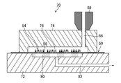
- the first mold 72 and the second mold 74 are clamped to form the cavity 76.
- the electroformed mold 50 is clamped by the first mold 72 and the second mold 74.
- the resin R is supplied from the injection molding machine 88 to the cavity 76 through the gate 86.
- the resin R is filled in the cavity 76 while passing between the convex patterns 54 of the electroforming mold 50.
- the resin R it is preferable to use a thermosetting resin or a silicone resin, and it is particularly preferable to use a silicone resin.
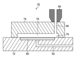
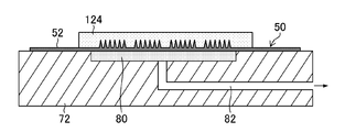
- the first mold 72 and the second mold 74 that have been clamped are opened. In the mold opening, the first mold 72 and the second mold 74 are moved so as to be relatively separated from each other. As shown in FIG. 8, the second mold 74 has a recess 84 for forming the cavity 76.
- the cured resin R is a mold 124 in which a plurality of concave patterns 130 before being released are formed.
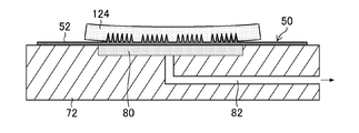
- the first mold 72 is separated from the second mold 74 and moved to a stage for releasing the mold 124 from the electroforming mold 50.
- the mold 124 is exposed except for the surface in contact with the electroforming mold 50 fixed to the first mold 72. Become. Therefore, when the mold 124 is released from the electroforming mold 50, the mold 124 can be easily released using the exposed surface of the mold 124.
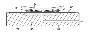
- the periphery of the mold 124 is first separated from the electroforming mold 50.
- the peripheral edge of the mold 124 only needs to include at least two opposite sides when the mold 124 is viewed in plan, and may include all four sides.
- the peripheral edge means a region from the outer periphery of the mold 124 to the concave pattern 130.
- the peripheral edge of the mold 124 is gradually separated from the electroforming mold 50.
- the mold 124 is made of a silicone resin
- the mold 124 has an elastic force. Therefore, when the peripheral portion of the mold 124 is gradually separated, the mold 124 is stretched (elastically deformed).
- the mold 124 that has been elastically deformed tends to return to its original shape, and thus the mold 124 contracts.
- the mold 124 is released from the electroforming mold 50 by utilizing the shrinkage force of the mold 124. By using the force that the mold 124 is trying to shrink as a releasing force, an excessive force is not applied between the mold 124 and the convex pattern 54 of the electroformed mold 50, thereby suppressing a release failure. Is possible.
- the mold 124 and the convex pattern 54 of the electroforming mold 50 are completely released, and the mold 124 having the concave pattern 130 is produced.
- the mold 124 is in a state where a plurality of molds 120 shown in FIG. 2 are connected.
- the electroforming mold 50 can be replaced in a short time by stopping the driving of a vacuum pump (not shown) and reducing the suction force of the suction plate 80.
- the exposed surface opposite to the surface on which the concave pattern 130 is formed As a method of separating the peripheral edge of the mold 124 from the electroforming mold 50, the exposed surface opposite to the surface on which the concave pattern 130 is formed, the peripheral edge of the mold 124 is sucked by suction means, and the peripheral edge is sucked.
- a method of separating the suction means from the electroforming mold 50 can be given.
- the mold 124 (mold 120) manufactured in this way is excellent in gas permeability.
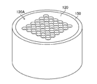
- FIG. 13 is a perspective view of the conveying jig 150 on which the mold 120 is mounted.
- the mold 120 is mounted on the conveying jig 150 and handled.
- the conveying jig 150 is made of plastic such as polypropylene.
- the conveying jig 150 supports the mold 120 in a state where the surface 120A of the mold 120 is directed upward in the Z direction, which is the vertical direction, and the sheet portion 102 of the mold 120 is parallel to the XY plane, which is a horizontal plane.
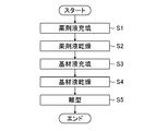
- FIG. 14 is a flowchart showing each step of the method for manufacturing the transdermal absorption sheet 100.
- the method for manufacturing the transdermal absorption sheet 100 includes a drug solution filling step (step S1) for filling the needle-shaped recess 132 of the mold 120 with a drug solution, a drug solution drying step (step S2) for drying the filled drug solution, and a needle shape.
- a substrate liquid filling step (step S3) for filling the recess 132 with the substrate solution, a substrate solution drying step (step S4) for drying the filled substrate solution, and the formed percutaneous absorption sheet 100 is separated from the mold 120.
- the mold release process (step S5) to mold is included.
- step S1 Drug solution filling step (step S1)]
- a liquid droplet of the chemical liquid is discharged from the nozzle 36 (see FIG. 15) of the chemical liquid discharge head 34 toward the needle-like recess 132 of the mold 120, and the mold 120 is drawn by the suction pump 22 (see FIG. 15). Aspirate. Details of the drug solution filling step will be described later.
- Step S2 Drug Solution Drying Step
- the chemical liquid filled in the needle-like concave portion 132 is dried by blowing air.
- the environment around the mold 120 may be reduced.
- Substrate liquid filling step (step S3) In the base material liquid filling step, the base liquid is filled into the needle-like recess 132.
- the base liquid is a drug-free polymer solution, and it is preferable to use a water-soluble polymer material such as chondroitin sulfate, hydroxyethyl starch, and dextran as the water-soluble polymer material forming the polymer solution.
- Step S4 In the base material liquid drying step, drying is performed by blowing air to the base material solution filled in the needle-like recess 132, as in the chemical liquid drying step.
- FIG. 15 is a schematic configuration diagram of a drug solution filling apparatus 1 (an example of a transdermal absorption sheet manufacturing apparatus) used in the drug solution filling step.
- the drug solution filling apparatus 1 includes an XYZ stage 10, an adsorption plate 20, a suction pump 22, a camera 30, a drug solution discharge head 34, and the like.
- the XYZ stage 10 (an example of a positioning unit) has a mounting surface 10A parallel to the XY plane.
- the XYZ stage 10 is provided by a motor (not shown) so as to be movable in two directions parallel to the XY plane and in the X direction and the Y direction orthogonal to the X direction. Further, the XYZ stage 10 is provided so as to be movable also in the Z direction and the R ⁇ Z direction which is a rotation direction with a direction parallel to the Z direction as a rotation axis.
- the suction plate 20 is fixed to the mounting surface 10A of the XYZ stage 10.
- the suction plate 20 has a placement surface 20A parallel to the XY plane.
- the mounting surface 20A is provided with a plurality of suction holes (not shown).
- the suction plate 20 may be made of a porous member.
- the suction plate 20 is connected to a suction pump 22 via a suction pipe 24.
- a suction pump 22 By driving the suction pump 22, air can be sucked from a plurality of suction holes (not shown) on the mounting surface 20 ⁇ / b> A of the suction plate 20.
- the conveying jig 150 is placed on the placement surface 20A of the suction plate 20.
- the mold 120 is mounted on the mounting surface 150A.
- the mold 120 moves in each direction as the XYZ stage 10 moves in the X direction, Y direction, Z direction, and R ⁇ Z direction.
- a plurality of suction holes 152 pass through the mounting surface 150A of the conveying jig 150.
- the suction pump 22 By driving the suction pump 22, the back surface 120 ⁇ / b> B of the mold 120 is sucked through the plurality of suction holes (not shown) on the mounting surface 20 ⁇ / b> A of the suction plate 20 and the plurality of suction holes 152 of the transport jig 150.
- the camera 30 includes an imaging element (not shown), an analog / digital conversion unit, and an image processing circuit in addition to the photographing lens 32.
- the photographing lens 32 is a lens group including a zoom lens, a focus lens, and the like, and makes incident light from a subject incident on an image sensor.
- the imaging device is a CCD (Charge-Coupled Device) type imaging device or a CMOS (Complementary Metal-Oxide Semiconductor) type imaging device in which a large number of light receiving elements are two-dimensionally arranged on an imaging surface (not shown).
- the image sensor is disposed in the subsequent stage of the optical path of the incident light of the photographing lens 32.
- the photographic lens 32 forms incident light on the imaging surface of the imaging device.
- the image sensor outputs an analog photographing signal corresponding to the amount of received light. This photographing signal is converted into a digital signal by an analog / digital converter, and then generated into an image signal by an image processing circuit.
- the camera 30 is disposed above the XYZ stage 10 in the Z direction, and the photographing lens 32 is directed downward in the Z direction. Thereby, the camera 30 can photograph the mold 120 placed on the XYZ stage 10.
- the drug solution ejection head 34 is disposed above the XYZ stage 10 in the Z direction and at a position away from the camera 30 by a distance d on the XY plane, which is composed of a distance d 1 in the X direction and a distance d 2 in the Y direction.
- the chemical liquid ejection head 34 includes a nozzle 36 (an example of a chemical liquid ejection nozzle) that ejects liquid droplets of the chemical liquid in the first direction.
- the nozzle 36 is directed downward in the Z direction, and the first direction is a downward direction in the Z direction.
- the chemical liquid ejection head 34 shown in FIG. 15 includes one nozzle 36, but may include a plurality of nozzles 36.
- the chemical liquid ejection head 34 may be an ink jet head such as a solenoid type ink jet head or a piezo type ink jet head.
- the amount of one droplet discharged from the nozzle 36 is about 1 to 150 nL.
- the chemical liquid discharged from the nozzle 36 flies downward in the Z direction and lands on the object (in this case, the mold 120). Therefore, the position on the XY plane of the nozzle 36 is equal to the position on the XY plane where the drug solution lands.
- the drug solution contains a drug stock solution, saccharides, additives and the like as a drug.
- medical solution contains water, ethanol, etc. as a solvent.
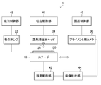
- FIG. 16 is a block diagram showing an electrical configuration of the drug solution filling apparatus 1.
- the drug solution filling apparatus 1 includes an imaging control unit 40, a movement control unit 42, an image detection unit 44, a discharge control unit 46, a suction control unit 48, and the like.
- the imaging control unit 40 causes the camera 30 to capture an image.
- the movement control unit 42 controls the relative movement between the mold 120 placed on the XYZ stage 10 and the drug solution ejection head 34.
- the mold 120 is moved by driving the XYZ stage 10, but the drug solution ejection head 34 may be moved, or both the mold 120 and the drug solution ejection head 34 may be moved. Good.
- the image detection unit 44 detects the position of the mold 120 based on the image of the mold 120 taken by the camera 30.
- the needle-like recess 132 is recognized from the image of the mold 120 and the position of the needle-like recess 132 is detected.
- the ejection control unit 46 controls the chemical liquid ejection head 34 to control the timing of ejecting the chemical liquid from the nozzle 36 and the amount of liquid droplets of the chemical liquid to be ejected.
- the suction control unit 48 controls the presence or absence of suction by the suction pump 22.
- FIG. 17 is a flowchart showing each step included in the drug solution filling step.
- the chemical liquid filling process includes a positioning adjustment process (step S11), a movement process (step S12), a chemical liquid discharge process (step S13), a discharge end determination process (step S14), a pass / fail determination process (step S15), and a suction process ( Step S16) is included.
- step S11 the positioning adjustment is performed so that the position of the needle-like concave portion 132 of the mold 120 placed on the XYZ stage 10 and the position of the nozzle 36 of the drug solution ejection head 34 coincide.
- the position of the needle-shaped recess 132 and the position of the nozzle 36 coincide with each other as long as the drug solution discharged from the nozzle 36 toward the needle-shaped recess 132 lands on the needle-shaped recess 132. It is not necessary that the positions of the two coincide.
- the needle-shaped recess 132 and the nozzle 36 are virtually positioned.
- the transfer jig 150 on which the mold 120 is mounted is placed on the placement surface 20A of the suction plate 20.
- the movement control unit 42 controls the XYZ stage 10 to move the mold 120 within the angle of view of the captured image of the camera 30.
- the imaging control unit 40 controls the camera 30 to capture an image of the mold 120 (an example of an imaging process).
- the image detection unit 44 analyzes the image of the mold 120 taken by the camera 30 and calculates the position of each needle-like recess 132.
- the XYZ stage 10 moves the needle-like recess 132 of the mold 120 to the center within the angle of view of the captured image of the camera 30, and detects the XY plane coordinates (X, Y) of the XYZ stage 10 at that time. By performing this operation for all the needle-like recesses 132, the positions of all the needle-like recesses 132 can be detected.
- the flat portion 122 has a relatively bright luminance
- the needle-like concave portion 132 has a relatively dark luminance.
- a plurality of alignment marks may be provided on the mold 120, and the XY plane coordinates (X, Y) of the needle-shaped recess 132 may be detected by reading the alignment marks.
- the needle-shaped concave portion 132 and the nozzle 36 are virtually positioned.
- mechanical positioning may be performed by a positioning adjustment jig or the like.
- the position (height) in the Z direction of the mold 120 may be adjusted by measuring the distance between the needle-shaped recess 132 or the alignment mark and the camera 30. It is preferable to adjust so that the distance between the nozzle 36 and the mold 120 is 0.5 mm to 5 mm, preferably 1 mm to 2 mm.
- the movement control unit 42 controls the XYZ stage 10 based on the detection result of the image detection unit 44 to move the mold 120 in the X direction and the Y direction, and the position of the nozzle 36 of the drug solution ejection head 34 on the XY plane. And the position of the needle-like recess 132 on the XY plane. That is, the position of the nozzle 36 and the position of the needle-shaped recess 132 are made to coincide with each other in a plan view from the direction (Z direction) parallel to the discharge direction of the drug solution of the nozzle 36.
- the movement control unit 42 moves the XYZ stage 10 to this coordinate.
- the discharge controller 46 controls the drug solution discharge head 34 to discharge the drug solution from the nozzle 36.
- the discharged drug solution lands on the needle-like recess 132.
- one drop of the drug solution is ejected from one nozzle 36 to one needle-like recess 132 and landed on the needle-like recess 132.
- a plurality of drops of drug solution may be landed on one needle-like recess 132.
- the drug solution that has landed in the needle-shaped recess 132 needs to close the needle-shaped recess 132, that is, contact the entire circumference of the wall of the needle-shaped recess 132.
- the drug solution landed in the suction step described later cannot be filled in the tapered tip of the tip recess 134. Therefore, when the position of the nozzle 36 and the position of the needle-like recess 132 are matched in the relative movement process, precise positional accuracy is required. For this reason, it is necessary to precisely adjust the positioning in the positioning adjustment step.
- discharge end determination step (step S14) The discharge controller 46 determines whether or not the drug solution has been discharged and landed on all the needle-like recesses 132 of the mold 120. Here, the determination is made by comparing the number of discharges of the drug solution discharged in the drug solution discharge step with the number of needle-like recesses 132 whose positions were detected in the positioning adjustment step.
- step S12 If it is determined that there is a needle-like recess 132 on which no drug solution is landed, the process returns to step S12 and the same processing is performed. That is, the position of the XY plane of the needle-like recess 132 that is not discharging the drug solution is matched with the position of the XY plane of the nozzle 36 (step S12), and the drug solution is discharged from the nozzle 36 to land on the needle-like recess 132 (Step S13).
- the order of discharging the drug solution to the needle-shaped recess 132 is not particularly limited, but from the viewpoint of shortening the total movement distance of the XYZ stage 10, the needle-shaped recesses sequentially disposed from the end of the mold 120 are sequentially adjacent to each other. It is preferable to discharge into the recess 132.
- step S15 If it is determined that the drug solution has landed on all the needle-like recesses 132, the process proceeds to step S15.
- Step S15 In the pass / fail judgment step, the imaging control unit 40 and the camera 30 image all the needle-like recesses 132 of the mold 120, and the number of the needle-like recesses 132 whose openings are closed by the drug solution is equal to or greater than a predetermined reference number. It is confirmed whether or not.
- This reference number is determined by the minimum number of needle-like convex portions 112 required for one transdermal absorption sheet 100.
- step S16 If the number of closed needle-like recesses 132 is less than the reference number, the process of this flowchart is terminated as a rejected product. If the number of closed needle-like recesses 132 is equal to or greater than the reference number, the process proceeds to step S16 as an acceptable product.
- Step S16 The suction control unit 48 drives the suction pump 22 to suck the back surface 120B of the mold 120. By this suction, the drug solution that has landed on the needle-like recess 132 is filled up to the tapered tip of the tip recess 134.
- the drug solution filling process is completed.
- the distance d 1 and the distance d 2 are treated as known values, but when unknown, they can be determined as follows.
- a dummy mold not provided with the needle-like recess 132 is mounted on the transport jig 150 and placed on the placement surface 20 ⁇ / b> A of the suction plate 20.
- the drug solution is discharged from the nozzle 36 to the dummy mold and landed on the dummy mold.
- the XYZ stage 10 is moved in the X direction and the Y direction so that the landed drug solution comes to the center of the angle of view of the captured image of the camera 30.
- the amount of movement in the X direction of the XYZ stage 10 is the distance d 1
- the amount of movement in the Y direction is the distance d 2 .
- FIG. 18 is a cross-sectional view for explaining the shape of the needle-like recess 132 according to the embodiment, and is a further enlarged view of FIG. 3.
- the tip recess 134 has a diameter of 300 ⁇ m and a height (depth) of 720 ⁇ m.
- the opening diameter of the cup portion 136 (opening diameter of the needle-like concave portion 132) is D, the angle formed by the flat portion 122 of the surface 120A of the mold 120 and the inside of the cup portion 136, and the angle inside the mold 120 is ⁇ .
- the height (depth) of the cup part 136 is a value determined from the opening diameter D and the angle ⁇ .
- the connecting portion (an example of the first edge portion of the opening of the needle-like concave portion) between the flat portion 122 and the cup portion 136 of the surface 120A is chamfered, and the radius of curvature (first radius of curvature) of the chamfered arc is R. And Since it is chamfered in this way, the angle ⁇ is an angle formed by an extension line of the flat portion 122 of the surface 120A and an extension line of the cup portion 136.
- the connecting portion (an example of the second edge portion) between the cup portion 136 and the tip recess portion 134 is chamfered, and the radius of curvature of the chamfered arc (second radius of curvature) is the same R as the first radius of curvature. .
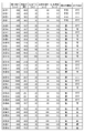
- FIG. 19 is a table showing the parameters of each level and the evaluation results. As shown in FIG. 19, the evaluation was performed for level 1 to level 32.
- the presence or absence of landing of the drug solution in the opening and the presence or absence of blockage of the opening by the drug solution were evaluated.
- the criteria for evaluating the presence or absence of landing of the drug solution in the opening of the drug solution was determined to be successful when the landing position of the discharged drug solution was inside the opening of the needle-like recess 132.
- the criterion for evaluating whether or not the opening is blocked by the drug solution is that the drug solution that has landed in the needle-like recess 132 is in contact with the entire circumference of the wall of the needle-like recess 132. It was judged.
- Judgment criteria are “excellent” when the success rate is 100%, “good” when the success rate is 98% or more and less than 100%, “good” when the success rate is 95% or more and less than 98%, success rate Is less than 95%.
- the opening diameter D is 500 ⁇ m
- the angle ⁇ is 45.0 degrees or 56.3 degrees
- the discharge amount A is 25 nL or 35 nL
- the curvature radius R is 30 ⁇ m
- the discharge speed V is 0.2 m / s. It is the level.
- the landing in the opening was “impossible”, and the closing of the opening was also “impossible”.
- Levels 5 to 8 have an opening diameter D of 600 ⁇ m, an angle ⁇ of 33.7 degrees or 45.0 degrees, a discharge amount A of 25 nL or 35 nL, a curvature radius R of 30 ⁇ m, and a discharge speed V of 0.2 m / s. It is the level.
- Level 2 and level 8 differ only in the value of the opening diameter D.
- Level 2 was “impossible” for landing within the opening and “impossible” for closing the opening, whereas level 8 was “excellent” for landing within the opening and “possible” for opening closing.
- the opening diameter D needs to be larger than 500 ⁇ m.
- the opening diameter D is small, it is considered that it is difficult to land the discharged drug solution on the needle-shaped recess depending on the positional accuracy between the nozzle 36 and the needle-shaped recess 132 in the relative movement process.
- both level 5 and level 7 are levels where the discharge amount A is 25 nL.
- Level 5 and level 6, and level 7 and level 8 differ only in the value of discharge amount A.
- the level 5 and level 7 opening blockage was “impossible”, whereas the level 6 and level 8 opening blockage was “possible”.
- the discharge amount needs to be larger than 25 nL.
- the opening diameter D is 600 ⁇ m
- the discharge amount A is 35 nL
- the curvature radius R is 30 ⁇ m
- the discharge speed V is 0.2 m / s
- the angle ⁇ is 63.4 degrees and 71.6 degrees, respectively.
- the level is 90.0 degrees.
- the level 11 has a shape having a cylindrical portion with an opening diameter D from the opening to a certain depth because the angle ⁇ is 90 degrees, and has a cup portion 136 and a tip recess 134 at the tip of the cylindrical portion. The angle of the cup part 136 was 45 degrees.
- the landing in the opening was “excellent” and the closing of the opening was “possible”.
- the opening diameter D is 600 ⁇ m
- the angle ⁇ is 45.0 degrees
- the curvature radius R is 30 ⁇ m
- the discharge speed V is 0.2 m / s
- the discharge amount A is 50 nL, 75 nL, and 150 nL, respectively. It is a level.
- Levels 12 to 14 were “excellent” for landing in the opening and “possible” for closing the opening. Thus, it was found that there is no problem even if the discharge amount A is increased to at least 150 nL.
- the reason why the evaluation of the opening blockage does not increase even when the discharge amount A is increased is that the radius of curvature R is 30 ⁇ m, so that the drug solution adhering to a part of the wall portion of the needle-shaped recess 132 is needle-shaped recess 132. It is considered that it is difficult to make contact over the entire circumference of the wall portion without being poured into the center of the wall.
- Levels 15 to 18 are levels in which the opening diameter D is 800 ⁇ m, the radius of curvature R is 30 ⁇ m, and the discharge speed V is 0.2 m / s.
- Levels 15 and 16 were levels in which the angle ⁇ was 21.8 degrees, and the opening blockage was “impossible”. When the angle ⁇ is small, when the landing position is deviated from the center of the opening, the drug solution adhering to a part of the wall of the needle-like recess 132 is not poured into the center of the needle-like recess 132, and the circumference of the wall This is thought to be because it becomes difficult to make contact throughout.
- Level 15 and level 17 were levels in which the discharge amount A was 25 nL, and the opening blockage was “impossible”. When the discharge amount A is small, it is considered that the drug solution adheres to a part of the wall portion of the needle-like recess 132 and it is difficult to make contact over the entire circumference of the wall portion.
- the opening blockage is “possible”.
- the opening diameter D is 800 ⁇ m
- the angle ⁇ needs to be larger than 21.8 degrees
- the discharge amount A needs to be larger than 25 nL.
- Levels 19 to 22 are levels in which the opening diameter D is 1000 ⁇ m, the radius of curvature R is 30 ⁇ m, and the discharge speed V is 0.2 m / s.
- Levels 19 and 20 were levels in which the angle ⁇ was 29.7 degrees, and the opening blockage was “impossible”.
- Level 19 and level 21 were levels in which the discharge amount A was 25 nL, and the opening blockage was “impossible”.
- the opening is closed. Accordingly, it was found that when the opening diameter D is 1000 ⁇ m, the angle ⁇ needs to be larger than 29.7 degrees and the discharge amount A needs to be larger than 25 nL.
- Levels 23 to 26 are levels in which the opening diameter D is 1200 ⁇ m, the radius of curvature R is 30 ⁇ m, and the discharge speed V is 0.2 m / s.
- Levels 23 and 24 were levels in which the angle ⁇ was 29.1 degrees, and the opening blockage was “impossible”.
- Levels 23 and 25 were levels in which the discharge amount A was 25 nL, and the opening blockage was “impossible”.
- the opening is closed.
- Levels 27 to 29 are levels in which the opening diameter D is 600 ⁇ m, the angle ⁇ is 45.0 degrees, the discharge amount A is 35 nL, the discharge speed V is 0.2 m / s, and the curvature radius R is 50 ⁇ m and 100 ⁇ mL, respectively. , 300 ⁇ m.
- the landing in the opening was “excellent” and the opening blockage was “good”.
- the radius of curvature R is large and smooth, even if the landing position of the drug solution that has landed inside the needle-shaped recess 132 is shifted from the center of the opening, the inner wall of the needle-shaped recess 132 is easily slid.
- Levels 30 to 32 are levels in which the opening diameter D is 600 ⁇ m, the angle ⁇ is 45.0 degrees, the discharge amount A is 35 nL, the radius of curvature R is 100 ⁇ m, and the discharge speed V is 0.3 m / s and 0, respectively. .5 m / s and 1.0 m / s.
- the landing in the opening was “excellent” and the opening obstruction was “excellent”.
- the discharge speed V is high, it is considered that the discharged drug solution can be easily collected or poured into the center of the needle-shaped recess 132.
- the opening diameter D can be 600 ⁇ m or more, the angle ⁇ can be 30.0 degrees or more, and the discharge amount A can be 30 nL or more.
- the discharged drug solution can be easily landed on the needle-like recess.
- the angle formed with the flat portion of the mold can be 30.0 degrees or more, the landed drug solution can be easily collected or poured into the center of the needle-shaped recess.
- the needle-like recess can be easily closed by setting the discharge amount of the drug solution to 30 nL or more. It is preferable that the opening diameter D is 1200 ⁇ m or less, the angle ⁇ is 90.0 degrees or less, and the discharge amount A is 150 nL or less.
- the radius of curvature R can be 30 ⁇ m or more, and the discharge speed V can be 0.2 m / s or more.
- the radius of curvature R is preferably 300 ⁇ m or less, and the discharge speed V is preferably in the range of 1.0 m / s.
- Drug solution filling device 10 XYZ stage 10A: Placement surface 20: Suction plate 20A: Placement surface 21: Level 22: Suction pump 24: Suction tube 30: Camera 32: Imaging lens 34: Drug solution ejection head 36: Nozzle 40: Imaging control unit 42: Movement control unit 44: Image detection unit 46: Discharge control unit 48: Suction control unit 50: Electroforming mold 52: First surface 54: Convex pattern 56: Needle-shaped convex part 58: First Two surfaces 70: Mold 72: First mold 74: Second mold 76: Cavity 78: Flat surface 80: Suction plate 82: Suction tube 84: Depression 86: Gate 88: Injection molding machine 100: Transdermal absorption sheet 100A: Surface 100B: Back surface 102: Sheet part 110: Convex pattern 112: Needle-like convex part 114: Needle part 116: Frustum part 120: Yield 120A: Front surface 120B: Back surface 122: Flat portion 124: Mold 130: Concave pattern 132: Needle
Landscapes
- Engineering & Computer Science (AREA)
- Health & Medical Sciences (AREA)
- Mechanical Engineering (AREA)
- Manufacturing & Machinery (AREA)
- Life Sciences & Earth Sciences (AREA)
- Biomedical Technology (AREA)
- Heart & Thoracic Surgery (AREA)
- Hematology (AREA)
- Anesthesiology (AREA)
- Animal Behavior & Ethology (AREA)
- General Health & Medical Sciences (AREA)
- Public Health (AREA)
- Veterinary Medicine (AREA)
- Medical Informatics (AREA)
- Dermatology (AREA)
- Media Introduction/Drainage Providing Device (AREA)
Abstract
針状凹部の先端に薬剤液を確実に充填するマイクロニードルアレイの製造方法を提供する。表面に針状凹部を有するモールドと薬剤液を吐出する薬剤液吐出ノズルとを位置決め調整する位置決め調整工程と、モールドと薬剤液吐出ノズルとを相対移動させて、薬剤液の吐出方向と平行な方向からの平面視において針状凹部の位置と薬剤液吐出ノズルの位置とを一致させる相対移動工程と、薬剤液吐出ノズルから針状凹部に向けて薬剤液を吐出する吐出工程と、モールドの裏面を吸引する吸引工程と、を備えるマイクロニードルアレイの製造方法、によって上記課題を解決する。
Description
本発明は、マイクロニードルアレイの製造方法に係り、特に、薬剤液吐出ノズルからモールドの針状凹部に薬剤液を吐出するマイクロニードルアレイの製造方法に関する。
近年、薬剤を含有する針状凸部(微小針又はマイクロニードルとも称する)の形成されたマイクロニードルアレイ(経皮吸収シート)が、薬剤を皮膚内に送達するために用いられている。一般的には、マイクロニードルアレイを皮膚に押し付けて、針状凸部を皮膚内に挿入することにより、針状凸部の薬剤が皮膚内に送達される。
マイクロニードルアレイを製造する方法としては、針状凸部の反転形状である針状凹部(針穴部とも称する)が形成されたモールドを用い、針穴部に薬剤を含む溶液(薬剤液とも称する)を充填し、乾燥させた後、針(ニードルとも称する)原料を含む溶液を塗布し、乾燥させることにより、マイクロニードルを形成する方法が知られている。
特に、薬剤液を充填する工程では、充填量が薬剤投与量に関わるため、極めて微量な薬剤液を、モールドシート毎に精度よく一定量で、確実に充填する必要がある。
これまで、薬剤液を充填するために、いくつかの方式が提案されている(特許文献1~4参照)。
しかしながら、特許文献1、2に記載の充填方法では、モールドの針状凹部へ薬剤液を精度よく充填することができないという問題点があった。
また、特許文献3、4では、モールドの針状凹部に液滴を吐出する充填方法を用いているが、生産性を上げるために高速で充填すると、液滴の着弾位置とモールドの針状凹部の位置とがずれてしまうという問題点があった。
薬剤液がモールドの針状凹部の中心から外れる、あるいは薬剤液が針状凹部の壁面に付着して針状凹部を塞ぐことができない場合には、薬剤液が針状凹部の先端へ充填できず、マイクロニードルアレイの製造の歩留まりが低下するという問題点がある。
本発明はこのような事情に鑑みてなされたものであり、針状凹部の先端に薬剤液を確実に充填するマイクロニードルアレイの製造方法を提供することを目的とする。
上記目的を達成するためにマイクロニードルアレイの製造方法の一の態様は、表面に針状凹部を有するモールドと薬剤液を第1方向に吐出する薬剤液吐出ノズルとを位置決め調整する位置決め調整工程と、モールドと薬剤液吐出ノズルとを相対移動させて、第1方向の平面視において針状凹部の位置と薬剤液吐出ノズルの位置とを一致させる相対移動工程と、薬剤液吐出ノズルから針状凹部に向けて薬剤液を吐出する吐出工程と、モールドの裏面を吸引する吸引工程と、を備えるマイクロニードルアレイの製造方法である。
本態様によれば、吐出した薬剤液を針状凹部に着弾させ、針状凹部の先端に充填することができる。なお、針状凹部の位置と薬剤液吐出ノズルの位置とを一致させるとは、薬剤液吐出ノズルから針状凹部に向けて吐出した薬剤液が針状凹部に着弾する程度に一致させればよく、厳密に両者の位置が一致している必要はない。
針状凹部は、開口径が600μm以上であり、モールドの平坦部との成す角度が30.0度以上であり、1つの針状凹部に吐出される薬剤液の吐出量は、30nL以上であることが好ましい。開口径を600μm以上とすることで吐出した薬剤液を針状凹部に着弾させやすくなり、モールドの平坦部との成す角度を30.0度以上とすることで着弾した薬剤液を針状凹部の中心に集めやすく又は流し込むことができ、薬剤液の吐出量を30nL以上とすることで針状凹部を閉塞しやすくすることができる。これにより、吐出した薬剤液を針状凹部に着弾させ、針状凹部の先端に充填することができる。
針状凹部は、開口径が1200μm以下であることが好ましい。これにより、吐出した薬剤液を針状凹部に着弾させることができる。
針状凹部は、角度が90.0度以下であることが好ましい。これにより、着弾させた薬剤液を針状凹部の中心に集めやすく又は流し込むことができる。
吐出量は、150nL以下であることが好ましい。これにより、吐出した薬剤液によって針状凹部を閉塞させることができる。
針状凹部の開口部の第1エッジ部は面取りされており、第1エッジ部の面取りの第1曲率半径は30μm以上であることが好ましい。これにより、針状凹部に着弾させた薬剤液が第1エッジ部にピン止めされることを防止し、薬剤液を針状凹部の中心に集めやすく又は流し込むことができ、針状凹部の先端に充填することができる。
第1曲率半径は、300μm以下であることが好ましい。これにより、針状凹部に着弾させた薬剤液が第1エッジ部にピン止めされることを防止し、薬剤液を針状凹部の中心に集めやすく又は流し込むことができ、針状凹部の先端に充填することができる。
針状凹部は、モールドの表面に設けられたカップ部と、カップ部と接続し、モールドの深さ方向に先細り形状を有する先端凹部と、を備え、カップ部と先端凹部との第2エッジ部は面取りされており、第2エッジ部の面取りの第2曲率半径は30μm以上であることが好ましい。これにより、針状凹部に着弾させた薬剤液が第2エッジ部にピン止めされることを防止し、薬剤液を針状凹部の中心に集めやすく又は流し込むことができ、針状凹部の先端に充填することができる。
第2曲率半径は、300μm以下であることが好ましい。これにより、針状凹部に吐出した薬剤液が第2エッジ部にピン止めされることを防止し、薬剤液を針状凹部の中心に集めやすく又は流し込むことができ、針状凹部の先端に充填することができる。
薬剤液吐出ノズルから吐出される薬剤液の飛翔速度が0.2m/s以上であることが好ましい。これにより、吐出した薬剤液を針状凹部の中心に集めやすく又は流し込むことができる。
薬剤液吐出ノズルから吐出される薬剤液の飛翔速度が1.0m/s以下であることが好ましい。これにより、吐出した薬剤液を針状凹部の中心に集めやすく又は流し込むことができる。
モールドの複数の位置を撮影する撮影工程を備え、位置決め調整工程は、撮影した複数の位置に基づいて針状凹部の位置を算出し、相対移動工程は、算出した結果に基づいて針状凹部の位置と薬剤液吐出ノズルから吐出される薬剤液の着弾位置とを一致させることが好ましい。これにより、吐出した薬剤液を針状凹部に適切に着弾させることができる。
モールドは複数の針状凹部を有し、吸引工程は、複数の針状凹部の全ての針状凹部に薬剤液が吐出されてからモールドの裏面を吸引することが好ましい。これにより、針状凹部に着弾させた薬剤液を確実に充填することができる。
モールドは気体透過性を有することが好ましい。これにより、適切に吸引することができるので、針状凹部に着弾させた薬剤液を確実に充填することができる。
針状凹部に充填された薬剤液を乾燥させる乾燥工程を備えることが好ましい。これにより、薬剤液を含むマイクロニードルアレイを製造することができる。
薬剤液は、薬剤原液、糖類、添加剤のうち少なくとも1つを含むことが好ましい。これにより、用途に応じたマイクロニードルアレイを製造することができる。
本発明によれば、針状凹部の先端に薬剤液を確実に充填することができる。
以下、添付図面にしたがって本発明の好ましい実施形態について説明する。本発明は以下の好ましい実施形態により説明される。本発明の範囲を逸脱すること無く、多くの手法により変更を行うことができ、本実施形態以外の他の実施形態を利用することができる。したがって、本発明の範囲内における全ての変更が特許請求の範囲に含まれる。
ここで、図中、同一の記号で示される部分は、同様の機能を有する同様の要素である。また、本明細書中で、数値範囲を“ ~ ”を用いて表す場合は、“ ~ ”で示される上限、下限の数値も数値範囲に含むものとする。
<経皮吸収シートの構成>
まず、本実施形態のマイクロニードルアレイの製造方法により製造されるマイクロニードルアレイ(経皮吸収シート)の一例について説明する。
まず、本実施形態のマイクロニードルアレイの製造方法により製造されるマイクロニードルアレイ(経皮吸収シート)の一例について説明する。
図1は、経皮吸収シート100の一例を示す斜視図である。経皮吸収シート100は、表面100A及び裏面100Bを有し、シート状のシート部102及び凸状パターン110から構成される。
シート状とは、面積の広い2つの対向する表面100A及び裏面100Bに対して厚みの薄い、全体として平たい形状を意味し、表面100A及び裏面100Bが完全に平坦である必要はない。また、図1に示すシート部102は平面視で円形であるが、矩形、多角形、楕円形等でもよい。
凸状パターン110は、複数の針状凸部112を有している。針状凸部112は、表面100Aに設けられている。針状凸部112は、ニードル部114と、ニードル部114とシート部102とを接続する錐台部116と、から構成される。
経皮吸収シート100の表面100Aには、複数個の錐台部116が形成される。錐台部116は、2つの底面を有し、錐体面で囲まれた立体構造を有している。錐台部116の2つの底面のうち面積の広い底面(下底面)がシート部102と接続される。錐台部116の2つの底面のうち面積の狭い底面(上底面)がニードル部114と接続される。つまり、錐台部116の2つの底面のうち、シート部102と離れる方向にある底面の面積が小さくなっている。
ニードル部114は、面積の広い底面と、底面から離れた先端が最も狭い面積となる形状を有している。ニードル部114の面積の広い底面が、錐台部116の上底面と接続されているので、ニードル部114は錐台部116と離れる方向に先細り形状となる。したがって、ニードル部114と錐台部116とで構成される針状凸部112は、全体としてシート部102から先端に向けて先細り形状を有している。シート部102の上には4~2500本の複数の針状凸部112が設けられる。但し、この本数に限定されない。
図1において、錐台部116は円錐台の形状を有し、ニードル部114は円錐の形状を有している。ニードル部114の皮膚への挿入の程度に応じて、ニードル部114の先端の形状を、0.01μm以上50μm以下の曲率半径の曲面、又は平坦面等に適宜変更することができる。
<モールドの構成>
図2は、経皮吸収シート100を製造するためのモールド120(経皮吸収シート製造用のモールド)の一例を示す斜視図である。また、図3は、図2の3-3断面の一部拡大図である。モールド120は、表面120A及び裏面120Bを有し、平坦部122及び凹状パターン130から構成されている。
図2は、経皮吸収シート100を製造するためのモールド120(経皮吸収シート製造用のモールド)の一例を示す斜視図である。また、図3は、図2の3-3断面の一部拡大図である。モールド120は、表面120A及び裏面120Bを有し、平坦部122及び凹状パターン130から構成されている。
平坦部122は、経皮吸収シート100のシート部102に対応する平坦な形状を有している。凹状パターン130は、複数の針状凹部132から構成される。針状凹部132は、経皮吸収シート100の針状凸部112に対応する形状を有しており、ニードル部114に対応する先端凹部134と、錐台部116に対応するカップ部136とから構成される。
先端凹部134は、モールド120の深さ方向に先細り形状を有している。先端凹部134は、径を150μm~500μm、高さを150μm~2000μmとすることができる。また、カップ部136は、モールド120の表面120Aに開口が設けられ、モールド120の深さ方向に狭くなる形状を有し、最も狭い部分で先端凹部134と接続されている。カップ部136は、径を500μm~1000μm、高さを100μm~500μmとすることができる。
なお、針状凹部132の形状はこの例に限定されない。先端凹部134とカップ部136との間に、円柱、四角柱、多角柱等の深さ方向に幅が一定の中間凹部を設けたロケット型としてもよい。また、先細り形状の先端に、裏面120Bに到達してモールド120を貫通する貫通孔を形成してもよい。針状凹部132の配列、ピッチ、数等は、経皮吸収シート100に必要な針状凸部112の配列、ピッチ、数等によって決定すればよい。
<モールドの作製方法>
射出成形によるモールドの作製方法について、図4から図12の工程図を参照して説明する。
射出成形によるモールドの作製方法について、図4から図12の工程図を参照して説明する。
図4に示されるように、第1型72と第2型74とを含む型70が準備される。第1型72と第2型74を型締めすることにより、型70の内部にキャビティ76が形成される。キャビティ76とは、樹脂が充填される空間を意味する。
また、図5に示されるように、電鋳金型50が準備される。電鋳金型50の第1面52には、作製したいモールドの反転形状である凸状パターン54が形成されている。凸状パターン54とは、複数の針状凸部56がアレイ状に配列された状態である。針状凸部56は作製したいモールドの形状に応じて作製される。
第1型72に電鋳金型50が固定されるので、電鋳金型50を固定する側は平坦面78で構成される。第1型72は、電鋳金型50を固定する装置として、平坦面78に吸着板80を備えている。第1型72は、その内部に吸着板80と気体連通する吸引管82を備えている。吸引管82は不図示の真空ポンプと接続されている。真空ポンプを駆動することにより、吸着板80の表面から空気を吸引することができる。吸着板80は、例えば、多孔質部材で構成される。多孔質部材として、例えば、金属焼結体、樹脂、及びセラミック等を挙げることができる。
第2型74のキャビティ76の側に窪み84が形成されている。本実施形態では、第1型72の平坦面78と、後述する第2型74の窪み84(図8参照)とによりキャビティ76が形成される。第1型72と第2型74とを上記の構成することにより、後述するように、モールドの離型が容易となる。
第2型74にはキャビティ76に連通するゲート86が形成されている。ゲート86が型70のキャビティ76への樹脂の注入口になる。ゲート86は、型70に樹脂を供給する射出成形機88と連通される。
図5に示されるように、第1型72と第2型74とが型開され、凸状パターン54を有する電鋳金型50が第1型72に載置される。吸引管82を介して真空ポンプにより空気を吸引することにより、電鋳金型50の第2面58が吸着板80に真空吸着される。
本実施形態では、真空吸着により電鋳金型50を第1型72に固定する場合を例示したが、これに限定されない。例えば、吸着板80に代えて、磁石を第1型72に設けることにより、磁力を利用して電鋳金型50を第1型72に固定することもできる。したがって、電鋳金型50を第1型72に真空吸着、及び磁力の少なくとも一方により固定することが好ましい。
図6に示されるように、キャビティ76を形成するため、第1型72と第2型74とが型締めされる。型締めする際、第1型72と第2型74とにより電鋳金型50が挟圧される。
図7に示されるように、樹脂Rが射出成形機88からゲート86を介してキャビティ76に供給される。樹脂Rは電鋳金型50の凸状パターン54の間を通過しながら、キャビティ76内に充填される。樹脂Rとしては、熱硬化性樹脂、又はシリコーン樹脂を用いることが好ましく、特に、シリコーン樹脂を用いることが好ましい。樹脂Rが型70のキャビティ76に充填されると、次いで、樹脂Rが加熱され、樹脂Rが硬化される。
図8に示されるように、電鋳金型50から硬化された樹脂Rを離型するため、型締めされていた第1型72と第2型74とが型開きされる。型開きでは、第1型72と第2型74とが相対的に離間するように移動される。図8に示されるように、第2型74は、キャビティ76を形成するための窪み84を有している。硬化された樹脂Rは、離型前の複数の凹状パターン130が形成されたモールド124である。
図9に示されるように、第1型72は、第2型74とは分離され、電鋳金型50からモールド124を離型するためのステージへと移動される。本実施形態では、窪み84を有する第2型74がモールド124から分離されるので、モールド124は、第1型72に固定された電鋳金型50と接触する面を除き、露出されることになる。したがって、電鋳金型50からモールド124を離型する際、モールド124の露出面を利用して容易に離型することが可能である。
図10に示されるように、モールド124の周縁部を電鋳金型50から最初に離間させる。モールド124の周縁部は、モールド124を平面視した際の対向する2辺を少なくとも含んでいれば良く、また、4辺の全てを含んでいても良い。周縁部とは、モールド124の外周から凹状パターン130までの領域を意味する。
図11に示されるように、モールド124の周縁部を徐々に電鋳金型50から離間させる。モールド124がシリコーン樹脂により作製される場合、モールド124は弾性力を有するので、モールド124の周縁部を徐々に離間させると、モールド124が伸ばされた状態(弾性変形)となる。モールド124の周縁部をさらに電鋳金型50から離間させると、弾性変形していたモールド124は元の形状に戻ろうとするため、モールド124は縮む。モールド124の縮む力を利用することにより、モールド124が電鋳金型50から離型される。モールド124が縮もうとする力を離型する力として利用することにより、モールド124と電鋳金型50の凸状パターン54との間に無理な力が加わらないので、離型不良を抑制することが可能となる。
図12に示されるように、最終的には、モールド124と電鋳金型50の凸状パターン54とは完全に離型され、凹状パターン130を有するモールド124が作製される。モールド124は、図2に示したモールド120が複数繋がった状態である。
電鋳金型50からモールド124を繰り返して作製する場合、凸状パターン54が徐々に傷むことから、1000回から10000回程度使用すると、新たな電鋳金型50に交換する必要がある。本実施形態では、不図示の真空ポンプの駆動を停止し、吸着板80の吸着力を低減することにより、電鋳金型50を短時間に交換することができる。
モールド124の周縁部を電鋳金型50から離間させる方法として、凹状パターン130の形成される面と反対の露出面であって、モールド124の周縁部を吸引手段で吸引し、周縁部を吸引しながら吸引手段を電鋳金型50から離間させる方法を挙げることができる。
このように作製したモールド124(モールド120)は、気体透過性が優れていることが望ましい。
<経皮吸収シートの製造方法>
図13は、モールド120を搭載した搬送治具150の斜視図である。経皮吸収シートの製造において、モールド120は搬送治具150に搭載されてハンドリングされる。搬送治具150は、ポリプロピレン等のプラスチックで構成される。搬送治具150は、モールド120の表面120Aを鉛直方向であるZ方向の上方に向けて、モールド120のシート部102を水平面であるXY平面と平行にした状態でモールド120を支持する。
図13は、モールド120を搭載した搬送治具150の斜視図である。経皮吸収シートの製造において、モールド120は搬送治具150に搭載されてハンドリングされる。搬送治具150は、ポリプロピレン等のプラスチックで構成される。搬送治具150は、モールド120の表面120Aを鉛直方向であるZ方向の上方に向けて、モールド120のシート部102を水平面であるXY平面と平行にした状態でモールド120を支持する。
図14は、経皮吸収シート100の製造方法の各工程を示すフローチャートである。経皮吸収シート100の製造方法は、モールド120の針状凹部132に薬剤液を充填する薬剤液充填工程(ステップS1)、充填した薬剤液を乾燥させる薬剤液乾燥工程(ステップS2)、針状凹部132に基材液を充填する基材液充填工程(ステップS3)、充填した基材液を乾燥させる基材液乾燥工程(ステップS4)、形成された経皮吸収シート100をモールド120から離型する離型工程(ステップS5)を含む。
〔薬剤液充填工程(ステップS1)〕
薬剤液充填工程は、薬剤液吐出ヘッド34のノズル36(図15参照)から薬剤液の液滴をモールド120の針状凹部132に向けて吐出し、吸引ポンプ22(図15参照)によってモールド120を吸引する。薬剤液充填工程の詳細については後述する。
薬剤液充填工程は、薬剤液吐出ヘッド34のノズル36(図15参照)から薬剤液の液滴をモールド120の針状凹部132に向けて吐出し、吸引ポンプ22(図15参照)によってモールド120を吸引する。薬剤液充填工程の詳細については後述する。
〔薬剤液乾燥工程(ステップS2)〕
薬剤液乾燥工程では、例えば、針状凹部132に充填された薬剤液に風を吹き付けることにより乾燥させる。モールド120の周囲環境を減圧してもよい。
薬剤液乾燥工程では、例えば、針状凹部132に充填された薬剤液に風を吹き付けることにより乾燥させる。モールド120の周囲環境を減圧してもよい。
〔基材液充填工程(ステップS3)〕
基材液充填工程では、針状凹部132に基材液を充填する。基材液は、薬剤非含有のポリマー溶液であり、ポリマー溶液を形成する水溶性の高分子物質としてはコンドロイチン硫酸、ヒドロキシエチルデンプン、デキストラン等の水溶性ポリマー物質を用いることが好ましい。
基材液充填工程では、針状凹部132に基材液を充填する。基材液は、薬剤非含有のポリマー溶液であり、ポリマー溶液を形成する水溶性の高分子物質としてはコンドロイチン硫酸、ヒドロキシエチルデンプン、デキストラン等の水溶性ポリマー物質を用いることが好ましい。
基材液を針状凹部132に充填する方法としては、例えばスピンコーターを用いた塗布を挙げることができる。
〔基材液乾燥工程(ステップS4)〕
基材液乾燥工程では、薬剤液乾燥工程と同様に、針状凹部132に充填された基材液に風を吹き付けることにより乾燥させる。
基材液乾燥工程では、薬剤液乾燥工程と同様に、針状凹部132に充填された基材液に風を吹き付けることにより乾燥させる。
〔離型工程(ステップS5)〕
離型工程では、薬剤液及び基材液が乾燥して形成されたシート(経皮吸収シート100)をモールド120から離型する。
離型工程では、薬剤液及び基材液が乾燥して形成されたシート(経皮吸収シート100)をモールド120から離型する。
<薬剤液充填装置>
図15は、薬剤液充填工程で使用する薬剤液充填装置1(経皮吸収シートの製造装置の一例)の概略構成図である。薬剤液充填装置1は、XYZステージ10、吸着板20、吸引ポンプ22、カメラ30、及び薬剤液吐出ヘッド34等を備えている。
図15は、薬剤液充填工程で使用する薬剤液充填装置1(経皮吸収シートの製造装置の一例)の概略構成図である。薬剤液充填装置1は、XYZステージ10、吸着板20、吸引ポンプ22、カメラ30、及び薬剤液吐出ヘッド34等を備えている。
XYZステージ10(位置決め部の一例)は、XY平面に平行な載置面10Aを有している。XYZステージ10は、不図示のモータにより、XY平面に平行な2方向であって、X方向及びX方向に直交するY方向を移動自在に設けられている。また、XYZステージ10は、Z方向、及びZ方向に平行な方向を回転軸とした回転方向であるRθZ方向についても移動可能に設けられている。
XYZステージ10の載置面10Aには、吸着板20が固定されている。吸着板20は、XY平面に平行な載置面20Aを有している。また、載置面20Aには、不図示の複数の吸着孔が設けられている。吸着板20は、多孔質部材で構成してもよい。
吸着板20は、吸引管24を介して吸引ポンプ22が接続されている。吸引ポンプ22を駆動することにより、吸着板20の載置面20Aの不図示の複数の吸着孔から空気を吸引することができる。
吸着板20の載置面20Aには、搬送治具150が載置される。搬送治具150には、載置面150Aにモールド120が搭載される。これにより、モールド120は、XYZステージ10のX方向、Y方向、Z方向、及びRθZ方向の移動に伴って各方向に移動する。
また搬送治具150の載置面150Aには、複数の吸着孔152が貫通している。吸引ポンプ22を駆動することにより、吸着板20の載置面20Aの不図示の複数の吸着孔、及び搬送治具150の複数の吸着孔152を介して、モールド120の裏面120Bを吸引する。
カメラ30は、撮影レンズ32の他、不図示の撮像素子、アナログデジタル変換部、及び画像処理回路を備えている。
撮影レンズ32は、ズームレンズ及びフォーカスレンズ等を備えたレンズ群であり、被写体からの入射光を撮像素子に入射させる。
撮像素子は、不図示の撮像面に多数の受光素子が2次元配列されたCCD(Charge Coupled Device)型の撮像素子又はCMOS(Complementary Metal Oxide Semiconductor)型の撮像素子である。撮像素子は、撮影レンズ32の入射光の光路の後段に配置される。
撮影レンズ32は、入射光を撮像素子の撮像面に結像させる。撮像素子は、受光量に応じたアナログの撮影信号を出力する。この撮影信号は、アナログデジタル変換部においてデジタル信号に変換された後、画像処理回路によって画像信号に生成される。
カメラ30は、XYZステージ10のZ方向の上方に配置されており、撮影レンズ32はZ方向の下方に向けられている。これにより、カメラ30は、XYZステージ10に載置されたモールド120を撮影することができる。
薬剤液吐出ヘッド34は、XYZステージ10のZ方向の上方であって、カメラ30からX方向の距離d1、Y方向の距離d2からなるXY平面における距離dだけ離れた位置に配置されている。薬剤液吐出ヘッド34は、薬剤液の液滴を第1方向に吐出するノズル36(薬剤液吐出ノズルの一例)を備えている。ここでは、ノズル36はZ方向下方に向けられており、第1方向はZ方向の下方向である。図15に示す薬剤液吐出ヘッド34は、1つのノズル36を備えているが、複数のノズル36を備えていてもよい。
薬剤液吐出ヘッド34は、例えばソレノイド型インクジェットヘッド、又はピエゾ型インクジェットヘッド等のインクジェットヘッドを用いることができる。ノズル36から吐出する1つの液滴量は、1~150nL程度である。
ノズル36から吐出される薬剤液は、Z方向下方に飛翔し、対象物(ここではモールド120)に着弾する。したがって、ノズル36のXY平面の位置と薬剤液の着弾するXY平面の位置とは等しい。
薬剤液は、薬剤として薬剤原液、糖類、添加剤等を含んでいる。また、薬剤液は、溶媒として水、又はエタノール等を含んでいる。
図16は、薬剤液充填装置1の電気的構成を示すブロック図である。薬剤液充填装置1は、撮影制御部40、移動制御部42、画像検出部44、吐出制御部46、及び吸引制御部48等を備えている。
撮影制御部40は、カメラ30に画像を撮影させる。
移動制御部42は、XYZステージ10に載置されたモールド120と薬剤液吐出ヘッド34との相対移動を制御する。ここでは、XYZステージ10を駆動することで、モールド120を移動させているが、薬剤液吐出ヘッド34を移動させてもよいし、モールド120と薬剤液吐出ヘッド34との両方を移動させてもよい。
画像検出部44は、カメラ30によって撮影したモールド120の画像に基づいて、モールド120の位置を検出する。本実施形態では、モールド120の画像から針状凹部132を認識し、針状凹部132の位置を検出する。
吐出制御部46は、薬剤液吐出ヘッド34を制御し、ノズル36から薬剤液を吐出するタイミング、及び吐出する薬剤液の液滴量を制御する。
吸引制御部48は、吸引ポンプ22による吸引の有無を制御する。
<薬剤液充填工程>
図17は、薬剤液充填工程に含まれる各工程を示すフローチャートである。薬剤液充填工程は、位置決め調整工程(ステップS11)、移動工程(ステップS12)、薬剤液吐出工程(ステップS13)、吐出終了判定工程(ステップS14)、良否判定工程(ステップS15)、吸引工程(ステップS16)を含んでいる。
図17は、薬剤液充填工程に含まれる各工程を示すフローチャートである。薬剤液充填工程は、位置決め調整工程(ステップS11)、移動工程(ステップS12)、薬剤液吐出工程(ステップS13)、吐出終了判定工程(ステップS14)、良否判定工程(ステップS15)、吸引工程(ステップS16)を含んでいる。
〔位置決め調整工程(ステップS11)〕
位置決め調整工程では、XYZステージ10に載置されたモールド120の針状凹部132の位置と薬剤液吐出ヘッド34のノズル36の位置とが一致するように、位置決め調整する。なお、針状凹部132の位置とノズル36の位置とが一致するとは、ノズル36から針状凹部132に向けて吐出した薬剤液が針状凹部132に着弾する程度に一致すればよく、厳密に両者の位置が一致している必要はない。ここでは、撮影画像から針状凹部132の位置を検出することで、針状凹部132とノズル36とを仮想的に位置決めする。
位置決め調整工程では、XYZステージ10に載置されたモールド120の針状凹部132の位置と薬剤液吐出ヘッド34のノズル36の位置とが一致するように、位置決め調整する。なお、針状凹部132の位置とノズル36の位置とが一致するとは、ノズル36から針状凹部132に向けて吐出した薬剤液が針状凹部132に着弾する程度に一致すればよく、厳密に両者の位置が一致している必要はない。ここでは、撮影画像から針状凹部132の位置を検出することで、針状凹部132とノズル36とを仮想的に位置決めする。
最初に、吸着板20の載置面20Aに、モールド120が搭載された搬送治具150を載置する。
移動制御部42は、XYZステージ10を制御し、カメラ30の撮影画像の画角内にモールド120を移動させる。撮影制御部40は、カメラ30を制御し、モールド120の画像を撮影させる(撮影工程の一例)。画像検出部44は、カメラ30によって撮影されたモールド120の画像を解析し、各針状凹部132の位置を算出する。
例えば、XYZステージ10によりモールド120の針状凹部132をカメラ30の撮影画像の画角内の中心に移動させ、その際のXYZステージ10のXY平面座標(X,Y)を検出する。これを全ての針状凹部132について行うことで、全ての針状凹部132の位置を検出することができる。
なお、カメラ30によって撮影されたモールド120の画像は、平坦部122は輝度が相対的に明るく、針状凹部132は輝度が相対的に暗い。このコントラストを用いることで、針状凹部132をカメラ30の撮影画像の画角内の中心に移動させることができる。
全ての針状凹部132についてカメラ30の撮影画像の画角内の中心に移動させるのではなく、3~5個の針状凹部132のXY平面座標(X,Y)のみを検出し、この座標からモールド120のXY平面内の向き(回転)、及びモールド120のXY平面内のズレや伸縮を解析することで、その他の針状凹部132の位置を検出してもよい。
また、モールド120に複数のアライメント用マークを設け、アライメント用マークを読み取ることで針状凹部132のXY平面座標(X,Y)を検出してもよい。
このように、XYZステージ10のXY平面座標(X,Y)による針状凹部132の位置を検出することで、針状凹部132とノズル36とを仮想的に位置決めする。なお、位置決め調整治具等により機械的な位置決めを行ってもよい。
さらに、針状凹部132、又はアライメント用マークとカメラ30との距離を計測し、モールド120のZ方向の位置(高さ)を調整してもよい。ノズル36とモールド120との距離が0.5mm~5mm、好ましくは1mm~2mmとなるように調整することが好ましい。
〔相対移動工程(ステップS12)〕
移動制御部42は、画像検出部44の検出結果に基づいて、XYZステージ10を制御してモールド120をX方向及びY方向に移動させて、薬剤液吐出ヘッド34のノズル36のXY平面の位置と針状凹部132のXY平面の位置とを一致させる。即ち、ノズル36の薬剤液の吐出方向と平行な方向(Z方向)からの平面視において、ノズル36の位置と針状凹部132の位置とを一致させる。
移動制御部42は、画像検出部44の検出結果に基づいて、XYZステージ10を制御してモールド120をX方向及びY方向に移動させて、薬剤液吐出ヘッド34のノズル36のXY平面の位置と針状凹部132のXY平面の位置とを一致させる。即ち、ノズル36の薬剤液の吐出方向と平行な方向(Z方向)からの平面視において、ノズル36の位置と針状凹部132の位置とを一致させる。
ステップS11で算出した針状凹部132の座標(X,Y)に、カメラ30と薬剤液吐出ヘッド34のノズル36とのX方向の距離d1、及びY方向の距離d2を加算した座標(X+d1,Y+d2)が、ノズル36の座標である。移動制御部42は、この座標にXYZステージ10を移動させる。
〔薬剤液吐出工程(ステップS13)〕
吐出制御部46は、薬剤液吐出ヘッド34を制御し、ノズル36から薬剤液を吐出させる。吐出された薬剤液は、針状凹部132に着弾する。ここでは、1つの針状凹部132に対してノズル36から1滴の薬剤液を吐出して、針状凹部132に着弾させる。なお、1つの針状凹部132に対して複数滴の薬剤液を着弾させてもよい。
吐出制御部46は、薬剤液吐出ヘッド34を制御し、ノズル36から薬剤液を吐出させる。吐出された薬剤液は、針状凹部132に着弾する。ここでは、1つの針状凹部132に対してノズル36から1滴の薬剤液を吐出して、針状凹部132に着弾させる。なお、1つの針状凹部132に対して複数滴の薬剤液を着弾させてもよい。
なお、針状凹部132内に着弾した薬剤液は、針状凹部132を閉塞、即ち針状凹部132の壁部の円周の全体に渡って接触している必要がある。着弾した薬剤液が針状凹部132を閉塞していない場合には、後述する吸引工程において着弾した薬剤液を先端凹部134の先細り形状の先端に充填することができない。したがって、相対移動工程においてノズル36の位置と針状凹部132の位置とを一致させる際には、精密な位置精度が要求される。このため、位置決め調整工程において、精密に位置決め調整する必要がある。
〔吐出終了判定工程(ステップS14)〕
吐出制御部46は、モールド120の全ての針状凹部132に薬剤液を吐出して着弾させたか否かを判定する。ここでは、薬剤液吐出工程において薬剤液を吐出した吐出数と位置決め調整工程において位置を検出した針状凹部132の数とを比較して判定する。
吐出制御部46は、モールド120の全ての針状凹部132に薬剤液を吐出して着弾させたか否かを判定する。ここでは、薬剤液吐出工程において薬剤液を吐出した吐出数と位置決め調整工程において位置を検出した針状凹部132の数とを比較して判定する。
薬剤液を着弾させていない針状凹部132があると判断した場合は、ステップS12に戻り、同様の処理を行う。即ち、薬剤液を吐出していない針状凹部132のXY平面の位置とノズル36のXY平面の位置とを一致させ(ステップS12)、ノズル36から薬剤液を吐出して針状凹部132に着弾させる(ステップS13)。針状凹部132に薬剤液を吐出する順序については特に限定されないが、XYZステージ10の総移動距離を短くする観点から、モールド120の端に配置された針状凹部132から、順次隣接する針状凹部132に吐出することが好ましい。
全ての針状凹部132に薬剤液を着弾させたと判断した場合は、ステップS15に移行する。
〔良否判定工程(ステップS15)〕
良否判定工程では、撮影制御部40及びカメラ30は、モールド120の全ての針状凹部132を撮影し、薬剤液によって開口が閉塞されている針状凹部132の数が予め定められた基準数以上であるか否かを確認する。この基準数は、1枚の経皮吸収シート100において必要となる針状凸部112の最低限の数によって決まる。
良否判定工程では、撮影制御部40及びカメラ30は、モールド120の全ての針状凹部132を撮影し、薬剤液によって開口が閉塞されている針状凹部132の数が予め定められた基準数以上であるか否かを確認する。この基準数は、1枚の経皮吸収シート100において必要となる針状凸部112の最低限の数によって決まる。
閉塞された針状凹部132の数が基準数未満の場合は、不合格品として本フローチャートの処理を終了する。閉塞された針状凹部132の数が基準数以上の場合は、合格品としてステップS16へ移行する。
〔吸引工程(ステップS16)〕
吸引制御部48は、吸引ポンプ22を駆動し、モールド120の裏面120Bを吸引する。この吸引により、針状凹部132に着弾した薬剤液は、先端凹部134の先細り形状の先端にまで充填される。
吸引制御部48は、吸引ポンプ22を駆動し、モールド120の裏面120Bを吸引する。この吸引により、針状凹部132に着弾した薬剤液は、先端凹部134の先細り形状の先端にまで充填される。
以上により、薬剤液充填工程が終了する。なお、薬剤液吐出工程と吸引工程とは、同時に行ってもよい。即ち、吸引ポンプ22により吸引を行いながらノズル36から薬剤液を吐出してもよい。
ここでは、距離d1、距離d2を既知の値として扱ったが、未知の場合は以下のようにして求めることができる。
針状凹部132の設けられていないダミーのモールドを搬送治具150に搭載し、吸着板20の載置面20Aに載置する。このダミーのモールドに対してノズル36から薬剤液を吐出し、ダミーのモールドに着弾させる。
次に、着弾した薬剤液がカメラ30の撮影画像の画角の中心に来るように、XYZステージ10をX方向及びY方向に移動させる。ここでのXYZステージ10のX方向移動量が距離d1、Y方向移動量が距離d2となる。
<実施例>
図18は、実施例に係る針状凹部132の形状を説明するための断面図であり、図3をさらに拡大した図である。図18に示すように、先端凹部134の径は300μm、高さ(深さ)は720μmである。カップ部136の開口径(針状凹部132の開口径)をD、モールド120の表面120Aの平坦部122とカップ部136の内側とが成す角度であって、モールド120内部の角度をθとする。なお、カップ部136の高さ(深さ)は、開口径Dと角度θから決まる値である。
図18は、実施例に係る針状凹部132の形状を説明するための断面図であり、図3をさらに拡大した図である。図18に示すように、先端凹部134の径は300μm、高さ(深さ)は720μmである。カップ部136の開口径(針状凹部132の開口径)をD、モールド120の表面120Aの平坦部122とカップ部136の内側とが成す角度であって、モールド120内部の角度をθとする。なお、カップ部136の高さ(深さ)は、開口径Dと角度θから決まる値である。
また、表面120Aの平坦部122とカップ部136との接続部(針状凹部の開口部の第1エッジ部の一例)は面取りされており、面取り円弧の曲率半径(第1曲率半径)をRとする。このように面取りされているため、角度θは、表面120Aの平坦部122の延長線とカップ部136との延長線とが成す角度とする。
さらに、カップ部136と先端凹部134との接続部(第2エッジ部の一例)は面取りされており、面取り円弧の曲率半径(第2曲率半径)は、第1曲率半径と同様のRである。
開口径D、角度θ、曲率半径R、ノズル36から吐出される薬剤液の吐出量A、及びノズル36から吐出される薬剤液の飛翔速度である吐出速度Vをパラメータとした各水準に対する針状凹部132への薬剤液の吐出(着弾)について評価を行った。図19は、各水準のパラメータとその評価結果を示す図表である。図19に示すように、水準1~水準32について評価を行った。
評価項目として、薬剤液の開口内への着弾の有無と、薬剤液による開口の閉塞の有無を評価した。薬剤液の開口内への着弾の有無の評価の基準は、吐出した薬剤液の着弾位置が針状凹部132の開口の内側である場合を成功と判断した。また、薬剤液による開口の閉塞の有無の評価の基準は、針状凹部132内に着弾した薬剤液が針状凹部132の壁部の円周の全体に渡って接触している場合を成功と判断した。
判定基準は、成功率が100%の場合を「優」、成功率が98%以上100%未満の場合を「良」、成功率が95%以上98%未満の場合を「可」、成功率が95%未満の場合を「不可」とした。
水準1~水準4は、開口径Dを500μm、角度θを45.0度又は56.3度、吐出量Aを25nL又は35nL、曲率半径Rを30μm、吐出速度Vを0.2m/sとした水準である。水準1~水準4は、開口内着弾が「不可」であり、これに伴い開口閉塞も「不可」であった。
水準5~水準8は、開口径Dを600μm、角度θを33.7度又は45.0度、吐出量Aを25nL又は35nL、曲率半径Rを30μm、吐出速度Vを0.2m/sとした水準である。
水準2と水準8とは、開口径Dの値だけが異なる。水準2は開口内着弾が「不可」、開口閉塞が「不可」であったのに対し、水準8は開口内着弾が「優」、開口閉塞が「可」であった。これにより、開口径Dは500μmよりも大きいことが必要であることがわかる。開口径Dが小さい場合には、相対移動工程におけるノズル36と針状凹部132との位置精度によっては、吐出した薬剤液を針状凹部に着弾させることが困難になるためと考えられる。
また、水準5及び水準7は、ともに吐出量Aが25nLの水準である。水準5と水準6、水準7と水準8とは、吐出量Aの値だけが異なる。水準5及び水準7の開口閉塞が「不可」であったのに対し、水準6及び水準8の開口閉塞は「可」であった。これにより、吐出量は25nLよりも多いことが必要であることがわかる。吐出量Aが少ない場合には、針状凹部132の壁部の一部に薬剤液が付着し、壁部の円周の全体に渡って接触することが困難になるためと考えられる。
水準9~水準11は、開口径Dを600μm、吐出量Aを35nL、曲率半径Rを30μm、吐出速度Vを0.2m/sとし、角度θをそれぞれ63.4度、71.6度、90.0度とした水準である。なお、水準11は、角度θを90度とした関係上、開口部から一定深さまでを開口径Dの円筒部とし、円筒部の先にカップ部136及び先端凹部134を有する形状とした。カップ部136の角度は45度とした。水準9~水準11は、開口内着弾が「優」であり、開口閉塞が「可」であった。これにより、角度θは少なくとも90.0度まで増加させても問題ないことがわかった。なお、角度θを増加させても開口閉塞の評価が上昇しない理由は、曲率半径Rを30μmとしているために、針状凹部132の壁部の一部に付着した薬剤液が針状凹部132の中心に流し込まれず、壁部の円周の全体に渡って接触することが困難になるためと考えられる。
水準12~水準14は、開口径Dを600μm、角度θを45.0度、曲率半径Rを30μm、吐出速度Vを0.2m/sとし、吐出量Aをそれぞれ50nL、75nL、150nLとした水準である。水準12~水準14は、開口内着弾が「優」、開口閉塞が「可」であった。これにより、吐出量Aは少なくとも150nLまで増加させても問題ないことがわかった。なお、吐出量Aを増加させても開口閉塞の評価が上昇しない理由は、曲率半径Rを30μmとしているために、針状凹部132の壁部の一部に付着した薬剤液が針状凹部132の中心に流し込まれず、壁部の円周の全体に渡って接触することが困難になるためと考えられる。
水準15~水準18は、開口径Dを800μm、曲率半径Rを30μm、吐出速度Vを0.2m/sとした水準である。水準15及び水準16は、角度θを21.8度とした水準であり、開口閉塞が「不可」であった。角度θが小さい場合は、着弾位置が開口の中心からずれた場合に、針状凹部132の壁部の一部に付着した薬剤液が針状凹部132の中心に流し込まれず、壁部の円周の全体に渡って接触することが困難になるためと考えられる。
水準15及び水準17は、吐出量Aを25nLとした水準であり、開口閉塞が「不可」であった。吐出量Aが少ない場合には、針状凹部132の壁部の一部に薬剤液が付着し、壁部の円周の全体に渡って接触することが困難になるためと考えられる。
これに対し、角度θを31.0度、吐出量Aを35nLとした水準18は、開口閉塞が「可」であった。これにより、開口径Dが800μmの場合は、角度θが21.8度より大きく、かつ吐出量Aが25nLより多いことが必要であることがわかった。
水準19~水準22は、開口径Dを1000μm、曲率半径Rを30μm、吐出速度Vを0.2m/sとした水準である。水準19及び水準20は、角度θを29.7度とした水準であり、開口閉塞が「不可」であった。水準19及び水準21は、吐出量Aを25nLとした水準であり、開口閉塞が「不可」であった。これに対し、角度θを35.5度、吐出量Aを35nLとした水準22は、開口閉塞が「可」であった。これにより、開口径Dが1000μmの場合は、角度θが29.7度より大きく、かつ吐出量Aが25nLより多いことが必要であることがわかった。
水準23~水準26は、開口径Dを1200μm、曲率半径Rを30μm、吐出速度Vを0.2m/sとした水準である。水準23及び水準24は、角度θを29.1度とした水準であり、開口閉塞が「不可」であった。水準23及び水準25は、吐出量Aを25nLとした水準であり、開口閉塞が「不可」であった。これに対し、角度θを33.7度、吐出量Aを35nLとした水準26は、開口閉塞が「可」であった。これにより、開口径Dが1200μmの場合は、角度θが29.1度より大きく、かつ吐出量Aが25nLより多いことが必要であることがわかった。
水準27~水準29は、開口径Dを600μm、角度θを45.0度、吐出量Aを35nL、吐出速度Vを0.2m/sとした水準であり、曲率半径Rをそれぞれ50μm、100μmL、300μmとした水準である。水準27~水準29は、開口内着弾が「優」、開口閉塞が「良」であった。曲率半径Rが大きく滑らかであると、針状凹部132の内部に着弾した薬剤液の着弾位置が開口の中心に対してずれていても、針状凹部132の内壁を滑りやすくなり、薬剤液が針状凹部132の円周全体に接触しやすいと考えられる。水準27~水準29の結果から、曲率半径Rの値は50μm~300μmの範囲で良好であることがわかった。なお、水準6等の結果から、曲率半径Rの値は30μmであっても問題ないことがわかっている。
水準30~水準32は、開口径Dを600μm、角度θを45.0度、吐出量Aを35nL、曲率半径Rを100μmとした水準であり、吐出速度Vをそれぞれ0.3m/s、0.5m/s、1.0m/sとした水準である。水準30~水準32は、開口内着弾が「優」、開口閉塞が「優」であった。吐出速度Vが速いと、吐出した薬剤液を針状凹部132の中心に集めやすく又は流し込むことができると考えられる。水準30~水準32の結果から、吐出速度Vの値は0.3m/s~1.0m/sの範囲で良好であることがわかった。なお、水準6等の結果から、吐出速度Vの値は0.2m/sであっても問題ないことがわかっている。
以上により、開口径Dは600μm以上、角度θは30.0度以上、吐出量Aは30nL以上の範囲とすることができる。開口径を600μm以上とすることで、吐出した薬剤液を針状凹部に着弾させやすくすることができる。また、モールドの平坦部との成す角度を30.0度以上とすることで、着弾した薬剤液を針状凹部の中心に集めやすく又は流し込むことができる。さらに、薬剤液の吐出量を30nL以上とすることで、針状凹部を閉塞しやすくすることができる。開口径Dは1200μm以下、角度θは90.0度以下、吐出量Aは150nL以下の範囲であることが好ましい。
また、曲率半径Rは30μm以上、吐出速度Vは0.2m/s以上の範囲とすることができる。曲率半径Rを30μm以上とすることで、針状凹部に吐出した薬剤液が第1エッジ部及び第2エッジ部にピン止めされることを防止し、薬剤液を針状凹部の中心に集めやすく又は流し込むことができ、針状凹部の先端に充填することができる。また、吐出速度Vを0.2m/s以上とすることで、吐出した薬剤液を針状凹部の中心に集めやすく又は流し込むことができる。曲率半径Rは300μm以下、吐出速度Vは1.0m/sの範囲であることが好ましい。
<その他>
本発明の技術的範囲は、上記の実施形態に記載の範囲には限定されない。各実施形態における構成等は、本発明の趣旨を逸脱しない範囲で、各実施形態間で適宜組み合わせることができる。
本発明の技術的範囲は、上記の実施形態に記載の範囲には限定されない。各実施形態における構成等は、本発明の趣旨を逸脱しない範囲で、各実施形態間で適宜組み合わせることができる。
1 :薬剤液充填装置
10 :XYZステージ
10A :載置面
20 :吸着板
20A :載置面
21 :水準
22 :吸引ポンプ
24 :吸引管
30 :カメラ
32 :撮影レンズ
34 :薬剤液吐出ヘッド
36 :ノズル
40 :撮影制御部
42 :移動制御部
44 :画像検出部
46 :吐出制御部
48 :吸引制御部
50 :電鋳金型
52 :第1面
54 :凸状パターン
56 :針状凸部
58 :第2面
70 :型
72 :第1型
74 :第2型
76 :キャビティ
78 :平坦面
80 :吸着板
82 :吸引管
84 :窪み
86 :ゲート
88 :射出成形機
100 :経皮吸収シート
100A :表面
100B :裏面
102 :シート部
110 :凸状パターン
112 :針状凸部
114 :ニードル部
116 :錐台部
120 :モールド
120A :表面
120B :裏面
122 :平坦部
124 :モールド
130 :凹状パターン
132 :針状凹部
134 :先端凹部
136 :カップ部
150 :搬送治具
150A :載置面
152 :吸着孔
S1~S5 経皮吸収シートの製造方法の各工程
S11~S16 薬剤液充填工程に含まれる各工程
Claims (16)
- 表面に針状凹部を有するモールドと薬剤液を第1方向に吐出する薬剤液吐出ノズルとを位置決め調整する位置決め調整工程と、
前記モールドと前記薬剤液吐出ノズルとを相対移動させて、前記第1方向の平面視において前記針状凹部の位置と前記薬剤液吐出ノズルの位置とを一致させる相対移動工程と、
前記薬剤液吐出ノズルから前記針状凹部に向けて薬剤液を吐出する吐出工程と、
前記モールドの裏面を吸引する吸引工程と、
を備えるマイクロニードルアレイの製造方法。 - 前記針状凹部は、開口径が600μm以上であり、前記モールドの平坦部との成す角度が30.0度以上であり、
1つの前記針状凹部に吐出される薬剤液の吐出量は、30nL以上である請求項1に記載のマイクロニードルアレイの製造方法。 - 前記針状凹部は、前記開口径が1200μm以下である請求項2に記載のマイクロニードルアレイの製造方法。
- 前記針状凹部は、前記角度が90.0度以下である請求項2又は3に記載のマイクロニードルアレイの製造方法。
- 前記吐出量は、150nL以下である請求項2から4のいずれか1項に記載のマイクロニードルアレイの製造方法。
- 前記針状凹部の開口部の第1エッジ部は面取りされており、前記第1エッジ部の面取りの第1曲率半径は30μm以上である請求項2から5のいずれか1項に記載のマイクロニードルアレイの製造方法。
- 前記第1曲率半径は、300μm以下である請求項6に記載のマイクロニードルアレイの製造方法。
- 前記針状凹部は、
前記モールドの表面に設けられたカップ部と、
前記カップ部と接続し、前記モールドの深さ方向に先細り形状を有する先端凹部と、
を備え、
前記カップ部と前記先端凹部との第2エッジ部は面取りされており、前記第2エッジ部の面取りの第2曲率半径は30μm以上である請求項1から7のいずれか1項に記載のマイクロニードルアレイの製造方法。 - 前記第2曲率半径は、300μm以下である請求項8に記載のマイクロニードルアレイの製造方法。
- 前記薬剤液吐出ノズルから吐出される前記薬剤液の飛翔速度が0.2m/s以上である請求項2から9のいずれか1項に記載のマイクロニードルアレイの製造方法。
- 前記薬剤液吐出ノズルから吐出される前記薬剤液の飛翔速度が1.0m/s以下である請求項10に記載のマイクロニードルアレイの製造方法。
- 前記モールドの複数の位置を撮影する撮影工程を備え、
前記位置決め調整工程は、前記撮影した複数の位置に基づいて前記針状凹部の位置を算出し、
前記相対移動工程は、前記算出した結果に基づいて前記針状凹部の位置と前記薬剤液吐出ノズルから吐出される薬剤液の着弾位置とを一致させる請求項1から11のいずれか1項に記載のマイクロニードルアレイの製造方法。 - 前記モールドは複数の前記針状凹部を有し、
前記吸引工程は、前記複数の針状凹部の全ての針状凹部に前記薬剤液が吐出されてから前記モールドの裏面を吸引する請求項1から12のいずれか1項に記載のマイクロニードルアレイの製造方法。 - 前記モールドは気体透過性を有する請求項1から13のいずれか1項に記載のマイクロニードルアレイの製造方法。
- 前記針状凹部に充填された薬剤液を乾燥させる乾燥工程を備える請求項1から14のいずれか1項に記載のマイクロニードルアレイの製造方法。
- 前記薬剤液は、薬剤原液、糖類、添加剤のうち少なくとも1つを含む請求項1から15のいずれか1項に記載のマイクロニードルアレイの製造方法。
Priority Applications (4)
| Application Number | Priority Date | Filing Date | Title |
|---|---|---|---|
| EP19776888.0A EP3777955B1 (en) | 2018-03-30 | 2019-03-25 | Microneedle array manufacturing method |
| CN201980016439.4A CN111801135B (zh) | 2018-03-30 | 2019-03-25 | 微针阵列的制造方法 |
| JP2020510052A JP7055861B2 (ja) | 2018-03-30 | 2019-03-25 | マイクロニードルアレイの製造方法 |
| US17/026,335 US20210001103A1 (en) | 2018-03-30 | 2020-09-21 | Manufacturing method of microneedle array |
Applications Claiming Priority (2)
| Application Number | Priority Date | Filing Date | Title |
|---|---|---|---|
| JP2018068102 | 2018-03-30 | ||
| JP2018-068102 | 2018-03-30 |
Related Child Applications (1)
| Application Number | Title | Priority Date | Filing Date |
|---|---|---|---|
| US17/026,335 Continuation US20210001103A1 (en) | 2018-03-30 | 2020-09-21 | Manufacturing method of microneedle array |
Publications (1)
| Publication Number | Publication Date |
|---|---|
| WO2019188935A1 true WO2019188935A1 (ja) | 2019-10-03 |
Family
ID=68058336
Family Applications (1)
| Application Number | Title | Priority Date | Filing Date |
|---|---|---|---|
| PCT/JP2019/012412 Ceased WO2019188935A1 (ja) | 2018-03-30 | 2019-03-25 | マイクロニードルアレイの製造方法 |
Country Status (5)
| Country | Link |
|---|---|
| US (1) | US20210001103A1 (ja) |
| EP (1) | EP3777955B1 (ja) |
| JP (1) | JP7055861B2 (ja) |
| CN (1) | CN111801135B (ja) |
| WO (1) | WO2019188935A1 (ja) |
Cited By (3)
| Publication number | Priority date | Publication date | Assignee | Title |
|---|---|---|---|---|
| WO2021230833A3 (en) * | 2020-05-14 | 2022-01-27 | Solen Cikolata Gida Sanayi Ve Ticaret Anonim Sirketi | A biscuit production assembly with thermal printing |
| KR20230014325A (ko) * | 2021-07-21 | 2023-01-30 | 한국기계연구원 | 피부 부착 박막의 제조를 위한 성형몰드 및 이를 이용한 피부 부착 박막 제조 방법 |
| JP2023513966A (ja) * | 2020-02-19 | 2023-04-04 | エルテーエス ローマン テラピー-ジステーメ アーゲー | マイクロ構造体を製造するための型要素 |
Families Citing this family (2)
| Publication number | Priority date | Publication date | Assignee | Title |
|---|---|---|---|---|
| CN113679693A (zh) * | 2021-07-28 | 2021-11-23 | 长春工业大学 | 一种雾化式可溶性抗菌消炎微针贴片的制备方法 |
| DE102022106125A1 (de) | 2022-03-16 | 2023-09-21 | Herbert Ginzinger | Vergießanlage |
Citations (6)
| Publication number | Priority date | Publication date | Assignee | Title |
|---|---|---|---|---|
| JP2008142183A (ja) * | 2006-12-07 | 2008-06-26 | Fujifilm Corp | マイクロニードルシート及びその製造方法 |
| JP2010069253A (ja) | 2008-09-22 | 2010-04-02 | Fujifilm Corp | 経皮吸収シート及びその製造方法 |
| JP2012200572A (ja) * | 2011-03-28 | 2012-10-22 | Toray Eng Co Ltd | マイクロニードルシートおよびその製造方法 |
| JP2013162982A (ja) | 2012-02-13 | 2013-08-22 | Fujifilm Corp | マイクロニードルシートの製造方法 |
| WO2014077242A1 (ja) | 2012-11-13 | 2014-05-22 | 富士フイルム株式会社 | 経皮吸収シートの製造方法 |
| JP2016112169A (ja) | 2014-12-15 | 2016-06-23 | 日本写真印刷株式会社 | マイクロニードルアレイ製造装置及びマイクロニードルアレイの製造方法並びにマイクロニードルアレイを有する製品 |
Family Cites Families (14)
| Publication number | Priority date | Publication date | Assignee | Title |
|---|---|---|---|---|
| US6908453B2 (en) * | 2002-01-15 | 2005-06-21 | 3M Innovative Properties Company | Microneedle devices and methods of manufacture |
| GB2448493B (en) * | 2007-04-16 | 2009-10-14 | Dewan Fazlul Hoque Chowdhury | Microneedle transdermal delivery device |
| US7648220B2 (en) * | 2007-04-23 | 2010-01-19 | Hewlett-Packard Development Company, L.P. | Sensing of fluid ejected by drop-on-demand nozzles |
| JP5568324B2 (ja) * | 2010-01-15 | 2014-08-06 | 凸版印刷株式会社 | マイクロニードル製造方法 |
| JP6390615B2 (ja) * | 2013-06-03 | 2018-09-19 | 凸版印刷株式会社 | 針状体の製造方法 |
| WO2016033652A1 (en) * | 2014-09-03 | 2016-03-10 | Newsouth Innovations Pty Limited | Microfluidic devices and fabrication |
| JP6411395B2 (ja) * | 2015-03-10 | 2018-10-24 | 富士フイルム株式会社 | 経皮吸収シートの製造方法 |
| WO2017056894A1 (ja) * | 2015-09-30 | 2017-04-06 | 富士フイルム株式会社 | モールドの作製方法、パターンシートの製造方法、電鋳金型の作製方法、及び電鋳金型を用いたモールドの作製方法 |
| JP2017079980A (ja) * | 2015-10-27 | 2017-05-18 | 富士フイルム株式会社 | シートの製造方法 |
| JP6517126B2 (ja) * | 2015-10-28 | 2019-05-22 | 富士フイルム株式会社 | シートの製造方法 |
| JP6626403B2 (ja) * | 2016-05-10 | 2019-12-25 | 富士フイルム株式会社 | 凹状パターンを有するモールドの作製方法、及びパターンシートの製造方法 |
| EP3459584B1 (en) * | 2016-05-31 | 2021-03-31 | Nissha Co., Ltd. | Microneedle array and method of manufacturing same |
| KR101834317B1 (ko) * | 2016-07-13 | 2018-03-05 | 영남대학교 산학협력단 | 마이크로니들 제조 장치 및 방법 |
| CN106727273A (zh) * | 2017-03-02 | 2017-05-31 | 李成国 | 可溶性微针的制造方法 |
-
2019
- 2019-03-25 JP JP2020510052A patent/JP7055861B2/ja not_active Expired - Fee Related
- 2019-03-25 CN CN201980016439.4A patent/CN111801135B/zh active Active
- 2019-03-25 EP EP19776888.0A patent/EP3777955B1/en active Active
- 2019-03-25 WO PCT/JP2019/012412 patent/WO2019188935A1/ja not_active Ceased
-
2020
- 2020-09-21 US US17/026,335 patent/US20210001103A1/en not_active Abandoned
Patent Citations (6)
| Publication number | Priority date | Publication date | Assignee | Title |
|---|---|---|---|---|
| JP2008142183A (ja) * | 2006-12-07 | 2008-06-26 | Fujifilm Corp | マイクロニードルシート及びその製造方法 |
| JP2010069253A (ja) | 2008-09-22 | 2010-04-02 | Fujifilm Corp | 経皮吸収シート及びその製造方法 |
| JP2012200572A (ja) * | 2011-03-28 | 2012-10-22 | Toray Eng Co Ltd | マイクロニードルシートおよびその製造方法 |
| JP2013162982A (ja) | 2012-02-13 | 2013-08-22 | Fujifilm Corp | マイクロニードルシートの製造方法 |
| WO2014077242A1 (ja) | 2012-11-13 | 2014-05-22 | 富士フイルム株式会社 | 経皮吸収シートの製造方法 |
| JP2016112169A (ja) | 2014-12-15 | 2016-06-23 | 日本写真印刷株式会社 | マイクロニードルアレイ製造装置及びマイクロニードルアレイの製造方法並びにマイクロニードルアレイを有する製品 |
Non-Patent Citations (1)
| Title |
|---|
| See also references of EP3777955A4 |
Cited By (5)
| Publication number | Priority date | Publication date | Assignee | Title |
|---|---|---|---|---|
| JP2023513966A (ja) * | 2020-02-19 | 2023-04-04 | エルテーエス ローマン テラピー-ジステーメ アーゲー | マイクロ構造体を製造するための型要素 |
| US12491664B2 (en) | 2020-02-19 | 2025-12-09 | Lts Lohmann Therapie-Systeme Ag | Mold element for manufacturing microstructures |
| WO2021230833A3 (en) * | 2020-05-14 | 2022-01-27 | Solen Cikolata Gida Sanayi Ve Ticaret Anonim Sirketi | A biscuit production assembly with thermal printing |
| KR20230014325A (ko) * | 2021-07-21 | 2023-01-30 | 한국기계연구원 | 피부 부착 박막의 제조를 위한 성형몰드 및 이를 이용한 피부 부착 박막 제조 방법 |
| KR102788775B1 (ko) | 2021-07-21 | 2025-04-01 | 한국기계연구원 | 피부 부착 박막의 제조를 위한 성형몰드 및 이를 이용한 피부 부착 박막 제조 방법 |
Also Published As
| Publication number | Publication date |
|---|---|
| JP7055861B2 (ja) | 2022-04-18 |
| JPWO2019188935A1 (ja) | 2021-04-01 |
| US20210001103A1 (en) | 2021-01-07 |
| EP3777955B1 (en) | 2023-07-26 |
| EP3777955A4 (en) | 2021-05-26 |
| CN111801135B (zh) | 2023-06-27 |
| EP3777955A1 (en) | 2021-02-17 |
| CN111801135A (zh) | 2020-10-20 |
Similar Documents
| Publication | Publication Date | Title |
|---|---|---|
| JP7055861B2 (ja) | マイクロニードルアレイの製造方法 | |
| US11452854B2 (en) | Method of manufacturing microneedle array | |
| EP3701998B1 (en) | Manufacturing method of microneedle array | |
| CN101622134B (zh) | 液滴分析系统 | |
| JP6390961B2 (ja) | 書込ヘッドユニットの組立装置および書込ヘッドユニットの組立方法 | |
| US20060214976A1 (en) | Method of Testing a Droplet Discharge Device | |
| CN106605453A (zh) | 喷墨印刷系统和处理晶圆的方法 | |
| JP7062049B2 (ja) | 経皮吸収シート製造用のモールド、針状凸部を有する経皮吸収シートの製造装置及び方法 | |
| KR20180060992A (ko) | 임프린트 장치, 임프린트 방법 및 물품의 제조 방법 | |
| US8544997B2 (en) | Liquid ejection head and manufacturing method thereof | |
| JP2003029115A (ja) | 撮像装置及びその焦点調整方法 | |
| US20200009875A1 (en) | Liquid ejection head and method of manufacturing liquid ejection head | |
| TWI631599B (zh) | 壓印裝置,測量方法,壓印方法,及物品製造方法 | |
| JP2005288412A (ja) | 液滴吐出装置、及び液滴吐出方法 | |
| JP6548560B2 (ja) | インプリント装置、計測方法、インプリント方法、および物品の製造方法 | |
| JP6037228B2 (ja) | 液滴吐出ヘッドの製造方法、液滴吐出ヘッドの製造装置及び液滴吐出ヘッド | |
| TW202431364A (zh) | 包含兩個位置檢測器的裝置、以及物品製造方法 | |
| JP6552392B2 (ja) | インプリント装置、計測方法、インプリント方法、および物品の製造方法 | |
| CN1393340A (zh) | 压电式喷墨头的制造方法 | |
| JPH1066918A (ja) | ペースト塗布装置 | |
| EP3204232A1 (en) | Printhead die assembly |
Legal Events
| Date | Code | Title | Description |
|---|---|---|---|
| 121 | Ep: the epo has been informed by wipo that ep was designated in this application |
Ref document number: 19776888 Country of ref document: EP Kind code of ref document: A1 |
|
| ENP | Entry into the national phase |
Ref document number: 2020510052 Country of ref document: JP Kind code of ref document: A |
|
| WWE | Wipo information: entry into national phase |
Ref document number: 2019776888 Country of ref document: EP |