WO2019189092A1 - 積層体、該積層体からなる包装材料、包装袋およびスタンドパウチ、並びに多層基材 - Google Patents
積層体、該積層体からなる包装材料、包装袋およびスタンドパウチ、並びに多層基材 Download PDFInfo
- Publication number
- WO2019189092A1 WO2019189092A1 PCT/JP2019/012708 JP2019012708W WO2019189092A1 WO 2019189092 A1 WO2019189092 A1 WO 2019189092A1 JP 2019012708 W JP2019012708 W JP 2019012708W WO 2019189092 A1 WO2019189092 A1 WO 2019189092A1
- Authority
- WO
- WIPO (PCT)
- Prior art keywords
- density polyethylene
- layer
- thickness
- film
- laminate
- Prior art date
- Legal status (The legal status is an assumption and is not a legal conclusion. Google has not performed a legal analysis and makes no representation as to the accuracy of the status listed.)
- Ceased
Links
Images


Classifications
-
- B—PERFORMING OPERATIONS; TRANSPORTING
- B65—CONVEYING; PACKING; STORING; HANDLING THIN OR FILAMENTARY MATERIAL
- B65D—CONTAINERS FOR STORAGE OR TRANSPORT OF ARTICLES OR MATERIALS, e.g. BAGS, BARRELS, BOTTLES, BOXES, CANS, CARTONS, CRATES, DRUMS, JARS, TANKS, HOPPERS, FORWARDING CONTAINERS; ACCESSORIES, CLOSURES, OR FITTINGS THEREFOR; PACKAGING ELEMENTS; PACKAGES
- B65D31/00—Bags or like containers made of paper and having structural provision for thickness of contents
- B65D31/02—Bags or like containers made of paper and having structural provision for thickness of contents with laminated walls
-
- B—PERFORMING OPERATIONS; TRANSPORTING
- B32—LAYERED PRODUCTS
- B32B—LAYERED PRODUCTS, i.e. PRODUCTS BUILT-UP OF STRATA OF FLAT OR NON-FLAT, e.g. CELLULAR OR HONEYCOMB, FORM
- B32B27/00—Layered products comprising a layer of synthetic resin
- B32B27/06—Layered products comprising a layer of synthetic resin as the main or only constituent of a layer, which is next to another layer of the same or of a different material
- B32B27/08—Layered products comprising a layer of synthetic resin as the main or only constituent of a layer, which is next to another layer of the same or of a different material of synthetic resin
-
- B—PERFORMING OPERATIONS; TRANSPORTING
- B32—LAYERED PRODUCTS
- B32B—LAYERED PRODUCTS, i.e. PRODUCTS BUILT-UP OF STRATA OF FLAT OR NON-FLAT, e.g. CELLULAR OR HONEYCOMB, FORM
- B32B27/00—Layered products comprising a layer of synthetic resin
- B32B27/16—Layered products comprising a layer of synthetic resin specially treated, e.g. irradiated
-
- B—PERFORMING OPERATIONS; TRANSPORTING
- B32—LAYERED PRODUCTS
- B32B—LAYERED PRODUCTS, i.e. PRODUCTS BUILT-UP OF STRATA OF FLAT OR NON-FLAT, e.g. CELLULAR OR HONEYCOMB, FORM
- B32B27/00—Layered products comprising a layer of synthetic resin
- B32B27/18—Layered products comprising a layer of synthetic resin characterised by the use of special additives
- B32B27/20—Layered products comprising a layer of synthetic resin characterised by the use of special additives using fillers, pigments, thixotroping agents
-
- B—PERFORMING OPERATIONS; TRANSPORTING
- B32—LAYERED PRODUCTS
- B32B—LAYERED PRODUCTS, i.e. PRODUCTS BUILT-UP OF STRATA OF FLAT OR NON-FLAT, e.g. CELLULAR OR HONEYCOMB, FORM
- B32B27/00—Layered products comprising a layer of synthetic resin
- B32B27/32—Layered products comprising a layer of synthetic resin comprising polyolefins
- B32B27/327—Layered products comprising a layer of synthetic resin comprising polyolefins comprising polyolefins obtained by a metallocene or single-site catalyst
-
- B—PERFORMING OPERATIONS; TRANSPORTING
- B32—LAYERED PRODUCTS
- B32B—LAYERED PRODUCTS, i.e. PRODUCTS BUILT-UP OF STRATA OF FLAT OR NON-FLAT, e.g. CELLULAR OR HONEYCOMB, FORM
- B32B37/00—Methods or apparatus for laminating, e.g. by curing or by ultrasonic bonding
- B32B37/12—Methods or apparatus for laminating, e.g. by curing or by ultrasonic bonding characterised by using adhesives
-
- B—PERFORMING OPERATIONS; TRANSPORTING
- B32—LAYERED PRODUCTS
- B32B—LAYERED PRODUCTS, i.e. PRODUCTS BUILT-UP OF STRATA OF FLAT OR NON-FLAT, e.g. CELLULAR OR HONEYCOMB, FORM
- B32B7/00—Layered products characterised by the relation between layers; Layered products characterised by the relative orientation of features between layers, or by the relative values of a measurable parameter between layers, i.e. products comprising layers having different physical, chemical or physicochemical properties; Layered products characterised by the interconnection of layers
- B32B7/04—Interconnection of layers
- B32B7/12—Interconnection of layers using interposed adhesives or interposed materials with bonding properties
-
- B—PERFORMING OPERATIONS; TRANSPORTING
- B65—CONVEYING; PACKING; STORING; HANDLING THIN OR FILAMENTARY MATERIAL
- B65D—CONTAINERS FOR STORAGE OR TRANSPORT OF ARTICLES OR MATERIALS, e.g. BAGS, BARRELS, BOTTLES, BOXES, CANS, CARTONS, CRATES, DRUMS, JARS, TANKS, HOPPERS, FORWARDING CONTAINERS; ACCESSORIES, CLOSURES, OR FITTINGS THEREFOR; PACKAGING ELEMENTS; PACKAGES
- B65D31/00—Bags or like containers made of paper and having structural provision for thickness of contents
- B65D31/08—Bags or like containers made of paper and having structural provision for thickness of contents with block bottoms
-
- B—PERFORMING OPERATIONS; TRANSPORTING
- B65—CONVEYING; PACKING; STORING; HANDLING THIN OR FILAMENTARY MATERIAL
- B65D—CONTAINERS FOR STORAGE OR TRANSPORT OF ARTICLES OR MATERIALS, e.g. BAGS, BARRELS, BOTTLES, BOXES, CANS, CARTONS, CRATES, DRUMS, JARS, TANKS, HOPPERS, FORWARDING CONTAINERS; ACCESSORIES, CLOSURES, OR FITTINGS THEREFOR; PACKAGING ELEMENTS; PACKAGES
- B65D31/00—Bags or like containers made of paper and having structural provision for thickness of contents
- B65D31/10—Bags or like containers made of paper and having structural provision for thickness of contents with gusseted sides
-
- B—PERFORMING OPERATIONS; TRANSPORTING
- B65—CONVEYING; PACKING; STORING; HANDLING THIN OR FILAMENTARY MATERIAL
- B65D—CONTAINERS FOR STORAGE OR TRANSPORT OF ARTICLES OR MATERIALS, e.g. BAGS, BARRELS, BOTTLES, BOXES, CANS, CARTONS, CRATES, DRUMS, JARS, TANKS, HOPPERS, FORWARDING CONTAINERS; ACCESSORIES, CLOSURES, OR FITTINGS THEREFOR; PACKAGING ELEMENTS; PACKAGES
- B65D65/00—Wrappers or flexible covers; Packaging materials of special type or form
- B65D65/38—Packaging materials of special type or form
- B65D65/40—Applications of laminates for particular packaging purposes
-
- B—PERFORMING OPERATIONS; TRANSPORTING
- B65—CONVEYING; PACKING; STORING; HANDLING THIN OR FILAMENTARY MATERIAL
- B65D—CONTAINERS FOR STORAGE OR TRANSPORT OF ARTICLES OR MATERIALS, e.g. BAGS, BARRELS, BOTTLES, BOXES, CANS, CARTONS, CRATES, DRUMS, JARS, TANKS, HOPPERS, FORWARDING CONTAINERS; ACCESSORIES, CLOSURES, OR FITTINGS THEREFOR; PACKAGING ELEMENTS; PACKAGES
- B65D75/00—Packages comprising articles or materials partially or wholly enclosed in strips, sheets, blanks, tubes or webs of flexible sheet material, e.g. in folded wrappers
- B65D75/008—Standing pouches, i.e. "Standbeutel"
-
- B—PERFORMING OPERATIONS; TRANSPORTING
- B32—LAYERED PRODUCTS
- B32B—LAYERED PRODUCTS, i.e. PRODUCTS BUILT-UP OF STRATA OF FLAT OR NON-FLAT, e.g. CELLULAR OR HONEYCOMB, FORM
- B32B2250/00—Layers arrangement
- B32B2250/02—2 layers
-
- B—PERFORMING OPERATIONS; TRANSPORTING
- B32—LAYERED PRODUCTS
- B32B—LAYERED PRODUCTS, i.e. PRODUCTS BUILT-UP OF STRATA OF FLAT OR NON-FLAT, e.g. CELLULAR OR HONEYCOMB, FORM
- B32B2250/00—Layers arrangement
- B32B2250/03—3 layers
-
- B—PERFORMING OPERATIONS; TRANSPORTING
- B32—LAYERED PRODUCTS
- B32B—LAYERED PRODUCTS, i.e. PRODUCTS BUILT-UP OF STRATA OF FLAT OR NON-FLAT, e.g. CELLULAR OR HONEYCOMB, FORM
- B32B2250/00—Layers arrangement
- B32B2250/05—5 or more layers
-
- B—PERFORMING OPERATIONS; TRANSPORTING
- B32—LAYERED PRODUCTS
- B32B—LAYERED PRODUCTS, i.e. PRODUCTS BUILT-UP OF STRATA OF FLAT OR NON-FLAT, e.g. CELLULAR OR HONEYCOMB, FORM
- B32B2250/00—Layers arrangement
- B32B2250/24—All layers being polymeric
- B32B2250/242—All polymers belonging to those covered by group B32B27/32
-
- B—PERFORMING OPERATIONS; TRANSPORTING
- B32—LAYERED PRODUCTS
- B32B—LAYERED PRODUCTS, i.e. PRODUCTS BUILT-UP OF STRATA OF FLAT OR NON-FLAT, e.g. CELLULAR OR HONEYCOMB, FORM
- B32B2255/00—Coating on the layer surface
- B32B2255/10—Coating on the layer surface on synthetic resin layer or on natural or synthetic rubber layer
-
- B—PERFORMING OPERATIONS; TRANSPORTING
- B32—LAYERED PRODUCTS
- B32B—LAYERED PRODUCTS, i.e. PRODUCTS BUILT-UP OF STRATA OF FLAT OR NON-FLAT, e.g. CELLULAR OR HONEYCOMB, FORM
- B32B2255/00—Coating on the layer surface
- B32B2255/20—Inorganic coating
-
- B—PERFORMING OPERATIONS; TRANSPORTING
- B32—LAYERED PRODUCTS
- B32B—LAYERED PRODUCTS, i.e. PRODUCTS BUILT-UP OF STRATA OF FLAT OR NON-FLAT, e.g. CELLULAR OR HONEYCOMB, FORM
- B32B2255/00—Coating on the layer surface
- B32B2255/20—Inorganic coating
- B32B2255/205—Metallic coating
-
- B—PERFORMING OPERATIONS; TRANSPORTING
- B32—LAYERED PRODUCTS
- B32B—LAYERED PRODUCTS, i.e. PRODUCTS BUILT-UP OF STRATA OF FLAT OR NON-FLAT, e.g. CELLULAR OR HONEYCOMB, FORM
- B32B2270/00—Resin or rubber layer containing a blend of at least two different polymers
-
- B—PERFORMING OPERATIONS; TRANSPORTING
- B32—LAYERED PRODUCTS
- B32B—LAYERED PRODUCTS, i.e. PRODUCTS BUILT-UP OF STRATA OF FLAT OR NON-FLAT, e.g. CELLULAR OR HONEYCOMB, FORM
- B32B2307/00—Properties of the layers or laminate
- B32B2307/30—Properties of the layers or laminate having particular thermal properties
- B32B2307/306—Resistant to heat
-
- B—PERFORMING OPERATIONS; TRANSPORTING
- B32—LAYERED PRODUCTS
- B32B—LAYERED PRODUCTS, i.e. PRODUCTS BUILT-UP OF STRATA OF FLAT OR NON-FLAT, e.g. CELLULAR OR HONEYCOMB, FORM
- B32B2307/00—Properties of the layers or laminate
- B32B2307/30—Properties of the layers or laminate having particular thermal properties
- B32B2307/31—Heat sealable
-
- B—PERFORMING OPERATIONS; TRANSPORTING
- B32—LAYERED PRODUCTS
- B32B—LAYERED PRODUCTS, i.e. PRODUCTS BUILT-UP OF STRATA OF FLAT OR NON-FLAT, e.g. CELLULAR OR HONEYCOMB, FORM
- B32B2307/00—Properties of the layers or laminate
- B32B2307/40—Properties of the layers or laminate having particular optical properties
- B32B2307/412—Transparent
-
- B—PERFORMING OPERATIONS; TRANSPORTING
- B32—LAYERED PRODUCTS
- B32B—LAYERED PRODUCTS, i.e. PRODUCTS BUILT-UP OF STRATA OF FLAT OR NON-FLAT, e.g. CELLULAR OR HONEYCOMB, FORM
- B32B2307/00—Properties of the layers or laminate
- B32B2307/50—Properties of the layers or laminate having particular mechanical properties
- B32B2307/514—Oriented
- B32B2307/516—Oriented mono-axially
-
- B—PERFORMING OPERATIONS; TRANSPORTING
- B32—LAYERED PRODUCTS
- B32B—LAYERED PRODUCTS, i.e. PRODUCTS BUILT-UP OF STRATA OF FLAT OR NON-FLAT, e.g. CELLULAR OR HONEYCOMB, FORM
- B32B2307/00—Properties of the layers or laminate
- B32B2307/50—Properties of the layers or laminate having particular mechanical properties
- B32B2307/514—Oriented
- B32B2307/518—Oriented bi-axially
-
- B—PERFORMING OPERATIONS; TRANSPORTING
- B32—LAYERED PRODUCTS
- B32B—LAYERED PRODUCTS, i.e. PRODUCTS BUILT-UP OF STRATA OF FLAT OR NON-FLAT, e.g. CELLULAR OR HONEYCOMB, FORM
- B32B2307/00—Properties of the layers or laminate
- B32B2307/70—Other properties
- B32B2307/72—Density
-
- B—PERFORMING OPERATIONS; TRANSPORTING
- B32—LAYERED PRODUCTS
- B32B—LAYERED PRODUCTS, i.e. PRODUCTS BUILT-UP OF STRATA OF FLAT OR NON-FLAT, e.g. CELLULAR OR HONEYCOMB, FORM
- B32B2307/00—Properties of the layers or laminate
- B32B2307/70—Other properties
- B32B2307/724—Permeability to gases, adsorption
- B32B2307/7242—Non-permeable
- B32B2307/7244—Oxygen barrier
-
- B—PERFORMING OPERATIONS; TRANSPORTING
- B32—LAYERED PRODUCTS
- B32B—LAYERED PRODUCTS, i.e. PRODUCTS BUILT-UP OF STRATA OF FLAT OR NON-FLAT, e.g. CELLULAR OR HONEYCOMB, FORM
- B32B2307/00—Properties of the layers or laminate
- B32B2307/70—Other properties
- B32B2307/724—Permeability to gases, adsorption
- B32B2307/7242—Non-permeable
- B32B2307/7246—Water vapor barrier
-
- B—PERFORMING OPERATIONS; TRANSPORTING
- B32—LAYERED PRODUCTS
- B32B—LAYERED PRODUCTS, i.e. PRODUCTS BUILT-UP OF STRATA OF FLAT OR NON-FLAT, e.g. CELLULAR OR HONEYCOMB, FORM
- B32B2307/00—Properties of the layers or laminate
- B32B2307/70—Other properties
- B32B2307/732—Dimensional properties
-
- B—PERFORMING OPERATIONS; TRANSPORTING
- B32—LAYERED PRODUCTS
- B32B—LAYERED PRODUCTS, i.e. PRODUCTS BUILT-UP OF STRATA OF FLAT OR NON-FLAT, e.g. CELLULAR OR HONEYCOMB, FORM
- B32B2307/00—Properties of the layers or laminate
- B32B2307/70—Other properties
- B32B2307/732—Dimensional properties
- B32B2307/734—Dimensional stability
-
- B—PERFORMING OPERATIONS; TRANSPORTING
- B32—LAYERED PRODUCTS
- B32B—LAYERED PRODUCTS, i.e. PRODUCTS BUILT-UP OF STRATA OF FLAT OR NON-FLAT, e.g. CELLULAR OR HONEYCOMB, FORM
- B32B2307/00—Properties of the layers or laminate
- B32B2307/70—Other properties
- B32B2307/75—Printability
-
- B—PERFORMING OPERATIONS; TRANSPORTING
- B32—LAYERED PRODUCTS
- B32B—LAYERED PRODUCTS, i.e. PRODUCTS BUILT-UP OF STRATA OF FLAT OR NON-FLAT, e.g. CELLULAR OR HONEYCOMB, FORM
- B32B2439/00—Containers; Receptacles
- B32B2439/40—Closed containers
- B32B2439/46—Bags
-
- B—PERFORMING OPERATIONS; TRANSPORTING
- B32—LAYERED PRODUCTS
- B32B—LAYERED PRODUCTS, i.e. PRODUCTS BUILT-UP OF STRATA OF FLAT OR NON-FLAT, e.g. CELLULAR OR HONEYCOMB, FORM
- B32B2553/00—Packaging equipment or accessories not otherwise provided for
-
- Y—GENERAL TAGGING OF NEW TECHNOLOGICAL DEVELOPMENTS; GENERAL TAGGING OF CROSS-SECTIONAL TECHNOLOGIES SPANNING OVER SEVERAL SECTIONS OF THE IPC; TECHNICAL SUBJECTS COVERED BY FORMER USPC CROSS-REFERENCE ART COLLECTIONS [XRACs] AND DIGESTS
- Y02—TECHNOLOGIES OR APPLICATIONS FOR MITIGATION OR ADAPTATION AGAINST CLIMATE CHANGE
- Y02W—CLIMATE CHANGE MITIGATION TECHNOLOGIES RELATED TO WASTEWATER TREATMENT OR WASTE MANAGEMENT
- Y02W30/00—Technologies for solid waste management
- Y02W30/50—Reuse, recycling or recovery technologies
- Y02W30/80—Packaging reuse or recycling, e.g. of multilayer packaging
Definitions
- the present invention relates to a laminate, a packaging material comprising the laminate, a packaging bag and a stand pouch, and a multilayer substrate.
- packaging materials and the like are produced using a resin film made of a resin material.
- a resin film made of polyethylene is widely used as a packaging material because it has appropriate flexibility and transparency and is excellent in heat sealability.
- a resin film composed of polyethylene is inferior in strength and heat resistance, so it cannot be used as a base material, and is used by being bonded to a resin film composed of polyester or polyamide.
- Ordinary packaging materials and the like are composed of laminated films in which the base material and the heat seal layer are made of different resin materials (for example, Patent Document 1).
- the inventors of the present invention can remarkably improve the strength and heat resistance of a polyethylene that has been conventionally used as a heat seal layer, and can be used as a substrate. It has been found that the use of a laminate with a heat seal layer composed of polyethylene makes it possible to produce a packaging material that has sufficient strength and heat resistance and can be recycled.
- the present invention has been made in view of the above knowledge, and the problem to be solved is to realize a packaging material having sufficient strength and heat resistance applicable as a packaging material and having excellent recyclability. It is to provide a laminate that can. Moreover, the subject which this invention tends to solve is providing the packaging material comprised from this laminated body. Moreover, the subject which this invention tends to solve is providing the packaging bag produced from this laminated body. Moreover, the problem to be solved by the present invention is to provide a stand pouch produced from the laminate. Furthermore, the problem to be solved by the present invention is to provide a multilayer base material that can be used for producing the laminate.
- the laminate of the present invention comprises at least a base material and a heat-sealable polyethylene layer,
- the base material and the heat seal layer are made of the same material,
- the base material has been stretched,
- the same material is polyethylene.
- the substrate includes a deposited film on at least one surface thereof.
- the laminate of the present invention includes an adhesive layer between the base material and the heat seal layer.
- the substrate comprises an aluminum deposited film
- the adhesive layer comprised by the hardened
- At least one of the base material and the heat seal layer includes polyethylene derived from biomass.
- the polyethylene content in the entire laminate is 90% by mass or more.
- the laminate of the present invention is used for packaging materials.
- the packaging material of the present invention is produced using the above laminate.
- the packaging bag of the present invention is manufactured using the above laminate, and the thickness of the heat seal layer is 20 ⁇ m or more and 60 ⁇ m or less.
- the stand pouch of the present invention is manufactured using the above laminate, and the thickness of the heat seal layer is 50 ⁇ m or more and 200 ⁇ m or less.
- the multilayer substrate of the present invention includes a high-density polyethylene layer, a medium-density polyethylene layer, a low-density polyethylene layer, a linear low-density polyethylene layer or an ultra-low-density polyethylene layer, a medium-density polyethylene layer, and a high-density polyethylene layer. And a five-layer co-extrusion stretched film.
- the thickness of the high-density polyethylene layer is 1 ⁇ m or more and 20 ⁇ m or less.
- the thickness of the medium density polyethylene layer is 1 ⁇ m or more and 30 ⁇ m or less.
- the thickness of the low-density polyethylene layer, the linear low-density polyethylene layer, or the ultra-low-density polyethylene layer is 1 ⁇ m or more and 10 ⁇ m or less.
- the multilayer substrate of the present invention includes a high-density polyethylene layer, a medium-density polyethylene layer, a blend resin layer of high-density polyethylene and medium-density polyethylene, a low-density polyethylene layer, a linear low-density polyethylene layer, or an ultra-low-density polyethylene. It comprises a seven-layer co-extrusion film of a layer, a medium density polyethylene layer, a blend resin layer of high density polyethylene and medium density polyethylene, and a high density polyethylene layer.
- strength applicable as a packaging material etc., heat resistance, and is excellent also in recyclability can be provided.
- the packaging material comprised from this laminated body can be provided.
- the packaging bag produced from this laminated body can be provided.
- the stand pouch produced from this laminated body can be provided.
- the multilayer base material which can be used for preparation of the said laminated body can be provided.
- the laminate 10 includes at least a base material 20 and a heat seal layer 30. Moreover, in one Embodiment, the laminated body 10 is provided with the intermediate
- the polyethylene content is preferably 90% by mass or more.
- the polyethylene content in the laminate means the ratio of the polyethylene content to the sum of the resin material contents in the layers constituting the laminate.
- the substrate is subjected to a stretching treatment, and this stretching treatment may be uniaxial stretching or biaxial stretching, but from the viewpoint of strength, biaxial stretching is preferable.
- the stretching ratio in the longitudinal direction (MD) of the substrate is preferably 2 times or more and 10 times or less, and preferably 3 times or more and 7 times or less.
- the draw ratio in the longitudinal direction (MD) is preferably 2 times or more and 10 times or less, and preferably 3 times or more and 7 times or less.
- the strength and heat resistance of the laminate of the present invention can be improved.
- the printability to a base material can be improved.
- the transparency of a base material can be improved, when an image is formed on the heat seal layer side surface of the base material, the visibility can be improved.
- the upper limit of the draw ratio in the longitudinal direction (MD) is not particularly limited, but is preferably 10 times or less from the viewpoint of the breaking limit of the substrate.
- the upper limit of the stretching ratio in the transverse direction (TD) is not particularly limited, but is preferably 10 times or less from the viewpoint of the breaking limit of the stretched polyethylene film.
- a base material is comprised with the material similar to a heat seal layer, and can improve the recyclability of a laminated body by this.
- the polyethylene high density polyethylene (HDPE), medium density polyethylene (MDPE), low density polyethylene (LDPE), linear low density polyethylene (LLDPE) and very low density polyethylene (VLDPE) can be used.
- the high-density polyethylene, density can be used 0.945 g / cm 3 or more polyethylene
- the medium density polyethylene, density 0.925 g / cm 3 or more 0.945 g / cm 3 less than the Polyethylene can be used.
- the low density polyethylene polyethylene having a density of 0.900 g / cm 3 or more and less than 0.925 g / cm 3 can be used.
- the density is A polyethylene having a density of 0.900 g / cm 3 or more and less than 0.925 g / cm 3 can be used.
- the ultra-low density polyethylene a polyethylene having a density of less than 0.900 g / cm 3 can be used.
- high-density polyethylene and medium-density polyethylene are preferable from the viewpoint of printability, strength and heat resistance of the laminate of the present invention, and appropriate stretching of the film, and medium-density polyethylene is more preferable from the viewpoint of proper stretching.
- the polyethylene having different density and branching as described above can be obtained by appropriately selecting the polymerization method.
- a polymerization catalyst using a multi-site catalyst such as a Ziegler-Natta catalyst or a single site catalyst such as a metallocene catalyst, any one of gas phase polymerization, slurry polymerization, solution polymerization, and high-pressure ion polymerization may be used. It is preferable to carry out in one stage or two or more stages.
- the above single-site catalyst is a catalyst that can form a uniform active species, and is usually adjusted by bringing a metallocene transition metal compound or a nonmetallocene transition metal compound into contact with an activation cocatalyst. .
- the single site catalyst is preferable because the active site structure is uniform as compared with the multisite catalyst, and a polymer having a high molecular weight and a high degree of uniformity can be polymerized.
- the metallocene-based catalyst is a catalyst containing a transition metal compound of Group IV of the periodic table containing a ligand having a cyclopentadienyl skeleton, a cocatalyst, and if necessary, an organometallic compound, and each catalyst component of the support. is there.
- the cyclopentadienyl skeleton is a cyclopentadienyl group, a substituted cyclopentadienyl group, or the like.
- substituted cyclopentadienyl groups include hydrocarbon groups having 1 to 30 carbon atoms, silyl groups, silyl substituted alkyl groups, silyl substituted aryl groups, cyano groups, cyanoalkyl groups, cyanoaryl groups, halogen groups, haloalkyl groups, halosilyl groups. It has at least one kind of substituent selected from a group and the like.
- the substituted cyclopentadienyl group may have two or more substituents, and the substituents are bonded to each other to form a ring, and an indenyl ring, a fluorenyl ring, an azulenyl ring, a hydrogenated product thereof, etc. It may be formed. Rings formed by bonding substituents to each other may further have substituents.
- transition metal compound of Group IV of the periodic table containing a ligand having a cyclopentadienyl skeleton examples include zirconium, titanium, hafnium and the like, and zirconium and hafnium are particularly preferable.
- the transition metal compound usually has two ligands having a cyclopentadienyl skeleton, and each ligand having a cyclopentadienyl skeleton is preferably bonded to each other via a bridging group.
- crosslinking group examples include C1-C4 alkylene groups, silylene groups, dialkylsilylene groups, substituted arylene groups such as diarylsilylene groups, and substituted germylene groups such as dialkylgermylene groups and diarylgermylene groups.
- it is a substituted silylene group.
- the transition metal compound of Group IV of the Periodic Table containing a ligand having the above cyclopentadienyl skeleton can use one kind or a mixture of two or more kinds as a catalyst component.
- the co-catalyst refers to a catalyst that can effectively make the above-mentioned group IV transition metal compound as a polymerization catalyst, or can neutralize ionic charges in a catalytically activated state.
- Co-catalysts include benzene-soluble aluminoxanes of organoaluminum oxy compounds, benzene-insoluble organoaluminum oxy compounds, ion-exchange layered silicates, boron compounds, active hydrogen group-containing or non-containing cations and non-coordinating anions.
- Ionic compounds, lanthanoid salts such as lanthanum oxide, tin oxide, phenoxy compounds containing a fluoro group, and the like.
- the group IV transition metal compound containing a ligand having a cyclopentadienyl skeleton may be used by being supported on an inorganic or organic compound carrier.
- the support is preferably a porous oxide of an inorganic or organic compound.
- an ion-exchange layered silicate such as montmorillonite, SiO 2 , Al 2 O 3 , MgO, ZrO 2 , TiO 2 , B 2 O 3 , CaO, ZnO, BaO, ThO 2 or the like, or a mixture thereof.
- examples of the organometallic compound used as necessary include organoaluminum compounds, organomagnesium compounds, and organozinc compounds. Of these, organic aluminum is preferably used.
- a copolymer of ethylene and another monomer can be used as long as the characteristics of the present invention are not impaired.
- the ethylene copolymer include a copolymer composed of ethylene and an ⁇ -olefin having 3 to 20 carbon atoms.
- the ⁇ -olefin having 3 to 20 carbon atoms include propylene, 1-butene, 1-pentene, 1-hexene, 1-octene, 1-decene, 1-dodecene, 1-tetradecene, 1-hexadecene, 1-octadecene, 1-eicocene, 3-methyl-1-butene, 4-methyl-1-pentene, 6-methyl- Examples include 1-heptene.
- a copolymer with vinyl acetate, an acrylic ester, etc. may be sufficient.
- biomass-derived ethylene may be used in place of ethylene obtained from fossil fuel as a raw material for obtaining the above high-density polyethylene and the like. Since such biomass-derived polyethylene is a carbon-neutral material, it can be made into a packaging material with even less environmental impact.
- Biomass-derived ethylene is obtained by fermenting sugar solution and starch obtained from plants such as sugarcane, corn, and sweet potato with microorganisms such as yeast to produce bioethanol and heating it in the presence of a catalyst. Can do.
- Such polyethylene derived from biomass can be produced, for example, by a method described in JP2013-177531A. Moreover, you may use the biomass-derived polyethylene (For example, green PE etc. which are marketed from a Braschem company) marketed.
- the content of polyethylene in the substrate is preferably 50% by mass or more, and more preferably 70% by mass or more.
- the stretched polyethylene film can contain additives as long as the properties of the present invention are not impaired.
- a cross-linking agent an antioxidant, an antiblocking agent, a slipping agent, an ultraviolet absorber, a light stabilizer
- examples thereof include fillers, reinforcing agents, antistatic agents, pigments, and modifying resins.
- the base material includes a layer composed of high-density polyethylene (hereinafter referred to as a high-density polyethylene layer) and a layer composed of medium-density polyethylene (hereinafter referred to as a medium-density polyethylene layer).
- a high-density polyethylene layer a layer composed of high-density polyethylene
- a medium-density polyethylene layer a layer composed of medium-density polyethylene
- a high density polyethylene layer By providing a high density polyethylene layer on the outside of the substrate, the strength and heat resistance of the laminate of the present invention can be further improved. Moreover, the stretching aptitude of a base material can be improved more by providing a medium density polyethylene layer.
- the structure which consists of a co-pressing film of a high density polyethylene layer and a medium density polyethylene layer from the outside.
- the drawability of a film can be improved.
- the strength and heat resistance of the laminate of the present invention can be improved.
- the thickness of the high-density polyethylene layer is preferably thinner than the thickness of the medium-density polyethylene layer.
- the ratio between the thickness of the high-density polyethylene layer and the thickness of the medium-density polyethylene layer is preferably 1/10 or more and 1/1 or less, and more preferably 1/5 or more and 1/2 or less.
- the strength and heat resistance of the laminate of the present invention can be further improved.
- the drawability of a base material can be improved more by making ratio of the thickness of a high density polyethylene layer and the thickness of a medium density polyethylene layer into 1/1 or less.
- the structure which consists of a three-layer co-pressing film of a high density polyethylene layer, a medium density polyethylene layer, and a high density polyethylene layer from the outside.
- stretching aptitude of a base material can be improved more.
- strength and heat resistance of the laminated body of this invention can be improved more.
- the occurrence of curling in the substrate can be prevented.
- the thickness of the high-density polyethylene layer is preferably thinner than the thickness of the medium-density polyethylene layer.
- the ratio between the thickness of the high-density polyethylene layer and the thickness of the medium-density polyethylene layer is preferably 1/10 or more and 1/1 or less, and more preferably 1/5 or more and 1/2 or less.
- a high-density polyethylene layer 60 for example, from the outside, as shown in FIG. 4, a high-density polyethylene layer 60, a medium-density polyethylene layer 70, a low-density polyethylene layer, a linear low-density polyethylene layer, or an ultra-low-density polyethylene layer 80 (this paragraph) In FIG. 5, for the sake of simplicity, it is collectively referred to as a low-density polyethylene layer.), A medium-density polyethylene layer 90, and a high-density polyethylene layer 100.
- stretching aptitude of a base material can be improved.
- the strength and heat resistance of the laminate of the present invention can be improved.
- the occurrence of curling in the substrate can be prevented.
- the thickness of the high-density polyethylene layer is preferably thinner than the thickness of the medium-density polyethylene layer.
- the ratio between the thickness of the high-density polyethylene layer and the thickness of the medium-density polyethylene layer is preferably 1/10 or more and 1/1 or less, and more preferably 1/5 or more and 1/2 or less.
- the drawability of a base material can be improved by making ratio of the thickness of a high density polyethylene layer and the thickness of a medium density polyethylene layer into 1/1 or less.
- the thickness of the high density polyethylene layer is preferably the same as the thickness of the low density polyethylene layer or thicker than the thickness of the low density polyethylene.
- the ratio of the thickness of the high density polyethylene layer to the thickness of the low density polyethylene layer is preferably 1 / 0.25 or more and 1/2 or less, more preferably 1 / 0.5 or more and 1/1 or less. preferable.
- Heat resistance can be improved by making ratio of the thickness of a high density polyethylene layer and the thickness of a low density polyethylene layer into 1 / 0.25 or more.
- the adhesiveness between middle density polyethylene layers can be improved by making ratio of the thickness of a high density polyethylene layer and the thickness of a low density polyethylene layer into 1/1 or less.
- the thickness of each high-density polyethylene layer is preferably 1 ⁇ m or more and 20 ⁇ m or less, and more preferably 2 ⁇ m or more and 10 ⁇ m or less.
- the strength and heat resistance of the laminate of the present invention can be further improved.
- the processability of the laminated body of this invention can be improved more by making the thickness of a high-density polyethylene layer into 20 micrometers or less.
- each medium density polyethylene layer is preferably 1 ⁇ m or more and 30 ⁇ m or less, and more preferably 5 ⁇ m or more and 20 ⁇ m or less.
- the thickness of the medium density polyethylene layer is preferably 1 ⁇ m or more and 10 ⁇ m or less, and more preferably 2 ⁇ m or more and 5 ⁇ m or less.
- the substrate having such a configuration can be produced by, for example, an inflation method. Specifically, from the outside, a high-density polyethylene, a medium-density polyethylene layer, and a low-density polyethylene layer, a linear low-density polyethylene layer, or an ultra-low-density polyethylene layer are coextruded in a tube shape, and then face each other.
- a low-density polyethylene layer, a linear low-density polyethylene layer, or an ultra-low-density polyethylene layer can be produced by pressure-bonding them with a rubber roll or the like.
- the number of defective products in the production can be remarkably reduced, and finally the production efficiency can be improved.
- the inflation film forming machine stretching can be performed together, and thereby production efficiency can be further improved.
- a high-density polyethylene layer a blend resin layer of high-density polyethylene and medium-density polyethylene, a medium-density polyethylene layer, a low-density polyethylene layer, a linear low-density polyethylene layer, or an ultra-low-density polyethylene.
- a layer in the paragraph, for simplicity of description, collectively referred to as a low density polyethylene layer
- a medium density polyethylene layer a high density polyethylene and a blend resin layer of medium density polyethylene
- a high density polyethylene layer It can also be set as the structure of the seven layer co-pressing film which becomes.
- each high-density polyethylene layer is preferably 1 ⁇ m or more and 20 ⁇ m or less, and more preferably 2 ⁇ m or more and 10 ⁇ m or less.
- the thickness of the high-density polyethylene layer is preferably 1 ⁇ m or more, the strength and heat resistance of the laminate of the present invention can be further improved.
- the processability of the laminated body of this invention can be improved more by making the thickness of a high-density polyethylene layer into 20 micrometers or less.
- the thickness of the blend resin layer of each high-density polyethylene and medium-density polyethylene is preferably 1 ⁇ m or more and 20 ⁇ m or less, and more preferably 2 ⁇ m or more and 10 ⁇ m or less. Thereby, the adhesion between the high-density polyethylene layer and the medium-density polyethylene layer can be improved. Moreover, the workability of the laminate of the present invention can be improved.
- the blending ratio of the high-density polyethylene and the medium-density polyethylene in the blend resin layer is preferably 1: 9 to 9: 1, more preferably 3: 7 to 7: 3, based on mass. Thereby, the adhesion between the high-density polyethylene layer and the medium-density polyethylene layer can be improved.
- the thickness of the low density polyethylene layer is preferably 1 ⁇ m or more and 30 ⁇ m or less, and more preferably 5 ⁇ m or more and 20 ⁇ m or less.
- the thickness of the medium density polyethylene layer is preferably 1 ⁇ m or more and 10 ⁇ m or less, and more preferably 2 ⁇ m or more and 5 ⁇ m or less.
- the adhesion between the high density polyethylene layer and the medium density polyethylene layer can be further improved.
- the processability of the laminated body of this invention can be improved more by the thickness of a base material intermediate
- middle layer being 5 micrometers or less.
- the stretched polyethylene film having such a configuration can be produced by the above-described inflation method. By producing by such a method, the number of defective products in the production can be remarkably reduced, and finally the production efficiency can be improved. Further, in the inflation film forming machine, stretching can be performed together, and thereby production efficiency can be further improved.
- the base material is surface-treated.
- adhesiveness with an adjacent layer can be improved.
- the surface treatment method is not particularly limited. For example, corona discharge treatment, ozone treatment, low-temperature plasma treatment using oxygen gas and / or nitrogen gas, physical treatment such as glow discharge treatment, and oxidation using chemicals. Chemical treatment such as treatment may be mentioned.
- an anchor coat layer may be formed on the surface of the substrate using a conventionally known anchor coat agent.
- the thickness of the substrate is preferably 9 ⁇ m or more and 50 ⁇ m or less, and more preferably 12 ⁇ m or more and 30 ⁇ m or less.
- the base material has a metal such as aluminum or an inorganic oxide such as aluminum oxide, silicon oxide, magnesium oxide, calcium oxide, zirconium oxide, titanium oxide, boron oxide, hafnium oxide, barium oxide on one surface.
- the vapor deposition film containing is provided. Thereby, the gas barrier property of the laminated body by this invention can be improved. Among the above, it is preferable to form a deposited film with aluminum oxide because it has high transparency, does not deteriorate the visibility of an image formed on the substrate, and has excellent gas barrier properties.
- a vapor deposition method As a vapor deposition method, a conventionally known method can be adopted. For example, a physical vapor deposition method (Physical Vapor Deposition method, PVD method) such as a vacuum vapor deposition method, a sputtering method, an ion plating method, or a plasma chemical vapor deposition method. And chemical vapor deposition (chemical vapor deposition method, CVD method) such as thermal chemical vapor deposition and photochemical vapor deposition.
- PVD method Physical Vapor Deposition method
- CVD method chemical vapor deposition
- the thickness of the deposited film is preferably 0.002 ⁇ m or more and 0.4 ⁇ m or less, and more preferably 0.005 ⁇ m or more and 0.1 ⁇ m or less.
- a composite film composed of two or more layers of vapor-deposited films of different kinds of inorganic oxides can be used by using both physical vapor deposition and chemical vapor deposition.
- the degree of vacuum in the vapor deposition chamber is preferably about 10-2 to 10-8 mbar, particularly about 10-3 to 10-7 mbar before introducing oxygen, and about 10-1 to 10-6 mbar after introducing oxygen. In particular, about 10-2 to 10-5 mbar is preferable.
- the amount of oxygen introduced varies depending on the size of the vapor deposition machine.
- an inert gas such as argon gas, helium gas, nitrogen gas or the like may be used as a carrier gas within a range where there is no problem.
- the film conveying speed is preferably about 10 to 800 m / min, particularly about 50 to 600 m / min.
- the substrate may have images of characters, patterns, symbols, etc. formed on its surface. Since deterioration of the image over time can be prevented, it is preferable to form the image on the side of the base material where the heat seal layer is laminated.
- the image forming method is not particularly limited, and examples thereof include conventionally known printing methods such as gravure printing, offset printing, and flexographic printing. Among these, the flexographic printing method is preferable from the viewpoint of environmental load.
- the haze value of the base material is preferably 20% or less, and more preferably 10% or less. Thereby, the visibility of the formed image can be improved.
- the haze value of the substrate can be adjusted by changing the draw ratio. In the present invention, the haze value can be measured according to JIS K-7105.
- the base material can be obtained by melting a resin material containing polyethylene, forming the film by a melt extrusion method such as an inflation molding method or a T-die molding method, and then stretching. Since the stretching process can be performed more easily, it is preferable to produce the film by an inflation molding method.
- a substrate having a multilayer structure can be produced by melt coextrusion of a plurality of resin materials.
- the MFR of polyethylene is preferably 3 g / 10 min or more and 20 g / 10 min or less.
- the processability of the laminate of the present invention can be improved.
- it can prevent that a resin film will fracture
- MFR of polyethylene is 0.5 g / 10 min or more and 5 g / 10 min or less.
- the processability of the laminate of the present invention can be improved.
- film forming property can be improved by making MFR of polyethylene into 5 g / 10min or less.
- the heat seal layer is made of the same material as the base material, that is, polyethylene, high density polyethylene (HDPE), medium density polyethylene (MDPE), low density polyethylene (LDPE) and linear low density polyethylene (LLDPE), It contains at least one copolymer of ethylene and other monomers.
- polyethylene high density polyethylene (HDPE), medium density polyethylene (MDPE), low density polyethylene (LDPE) and linear low density polyethylene (LLDPE)
- HDPE high density polyethylene
- MDPE medium density polyethylene
- LDPE low density polyethylene
- LLDPE linear low density polyethylene
- LLDPE linear low density polyethylene
- the heat seal layer is formed by an unstretched polyethylene film or by melt extrusion of polyethylene.
- the polyethylene constituting the heat seal layer is preferably low density polyethylene (LDPE), linear low density polyethylene (LLDPE), or ultra-density polyethylene (VLDPE) from the viewpoint of heat sealability.
- LDPE low density polyethylene
- LLDPE linear low density polyethylene
- VLDPE ultra-density polyethylene
- a copolymer of ethylene and other monomers can be used. From the viewpoint of environmental burden, it is preferably biomass-derived polyethylene or recycled polyethylene.
- the content of polyethylene in the heat seal layer is preferably 50% by mass or more, and more preferably 70% by mass or more.
- the heat-sealable polyethylene layer can contain additives as long as the properties of the present invention are not impaired, for example, a crosslinking agent, an antioxidant, an ultraviolet absorber, a light stabilizer, a filler, a reinforcing agent, and an antistatic agent. Agents, pigments, modifying resins and the like.
- the heat seal layer has a multilayer structure, and includes a layer including at least one of medium density polyethylene and high density polyethylene as an intermediate layer.
- a layer containing at least one of low density polyethylene, linear low density polyethylene, and ultra-low density polyethylene a layer containing at least one of medium density polyethylene and high density polyethylene, low density polyethylene, It can be set as the structure which consists of a layer containing at least any one of a linear low density polyethylene and an ultra-low density polyethylene.
- the heat seal layer comprises a layer comprising at least one of low density polyethylene, linear low density polyethylene, and ultra-low density polyethylene / layer comprising biomass-derived polyethylene / low density polyethylene, straight It can be set as the structure which consists of a layer containing at least any one of chain
- the thickness of the heat seal layer is preferably changed as appropriate according to the weight of the contents filled in the packaging material produced by the laminate of the present invention.
- the thickness of the heat seal layer is preferably 20 ⁇ m or more and 60 ⁇ m or less.
- the thickness of the heat seal layer is preferably 50 ⁇ m or more and 200 ⁇ m or less.
- the thickness of the heat seal layer is preferably 50 ⁇ m or more and 200 ⁇ m or less.
- the heat seal layer is formed by forming a polyethylene film by forming a resin material containing polyethylene by a melt extrusion molding method such as inflation molding or T-die molding, and this is formed on a substrate through an adhesive layer described below. Or it can form by laminating
- thermoforming a heat seal layer by extruding a resin material containing polyethylene onto a polyethylene layer provided with a base material or a deposited film and drying it.
- the laminate of the present invention comprises an intermediate layer between the substrate and the heat seal layer.
- the intermediate layer includes a polyethylene film that has been stretched.
- the stretching may be uniaxial stretching or biaxial stretching.
- the stretch ratio in the longitudinal direction (MD) of the polyethylene film is preferably 2 to 10 times, and preferably 3 to 7 times.
- the draw ratio in the longitudinal direction (MD) of the polyethylene film is preferably 2 times or more, the strength and heat resistance of the laminate of the present invention can be improved.
- the upper limit of the draw ratio in the longitudinal direction (MD) of the polyethylene film is not particularly limited, but is preferably 10 times or less from the viewpoint of the breaking limit of the polyethylene film.
- the stretch ratio in the transverse direction (TD) of the polyethylene film is 2 times or more, and it is preferable that they are 3 times or more and 7 times or less in the transverse direction (TD) of a polyethylene film.
- the stretch ratio in the transverse direction (TD) of the polyethylene film is 2 times or more, the strength and heat resistance of the laminate of the present invention can be improved.
- the upper limit of the stretching ratio in the transverse direction (TD) of the polyethylene film is not particularly limited, but is preferably 10 times or less from the viewpoint of the breaking limit of the polyethylene film.
- the polyethylene contained in the polyethylene film is preferably high-density polyethylene and medium-density polyethylene from the viewpoint of strength and heat resistance and appropriate stretching of the film, and more preferably medium-density polyethylene from the viewpoint of appropriate stretching.
- the polyethylene film may have a multilayer structure as described above, similarly to the base material.
- the polyethylene film can contain the above additives as long as the characteristics of the present invention are not impaired.
- the thickness of the polyethylene film is preferably 9 ⁇ m or more and 50 ⁇ m or less, and more preferably 12 ⁇ m or more and 30 ⁇ m or less.
- the thickness of the polyethylene film is preferably 9 ⁇ m or more and 50 ⁇ m or less, and more preferably 12 ⁇ m or more and 30 ⁇ m or less.
- polyethylene film one produced by the T-die method or the inflation method may be used, or a commercially available one may be used.
- the polyethylene film includes a deposited film on at least one surface thereof.
- the gas barrier property of the laminated body by this invention can be improved.
- the thickness of the deposited film is preferably 0.002 ⁇ m or more and 0.4 ⁇ m or less, and more preferably 0.005 ⁇ m or more and 0.1 ⁇ m or less.
- An image may be formed on the surface of the polyethylene film.
- the image forming method is as described above.
- the polyethylene laminate for packaging material of the present invention can be provided with an adhesive layer between arbitrary layers.
- the adhesive layer includes at least one type of adhesive, and either one-component curable type, two-component curable type, or non-curable type may be an adhesive.
- the adhesive may be a solvent-free adhesive or a solvent-type adhesive, but a solvent-free adhesive can be preferably used from the viewpoint of environmental load.
- solventless adhesives include polyether adhesives, polyester adhesives, silicone adhesives, epoxy adhesives, and urethane adhesives. Among these, two-component curable urethanes are used.
- a system adhesive can be preferably used.
- the solvent-type adhesive include rubber adhesives, vinyl adhesives, silicone adhesives, epoxy adhesives, phenol adhesives, and olefin adhesives.
- an adhesive layer adjacent to the vapor deposition film which is an aluminum vapor deposition film it is preferable to comprise an adhesive layer with the hardened
- an adhesive layer with the hardened
- the polyester polyol has two or more hydroxyl groups in one molecule as a functional group. Moreover, an isocyanate compound has two or more isocyanate groups in 1 molecule as a functional group.
- the polyester polyol has, for example, a polyester structure or a polyester polyurethane structure as a main skeleton.
- a resin composition containing a polyester polyol, an isocyanate compound, and a phosphoric acid-modified compound As a specific example of a resin composition containing a polyester polyol, an isocyanate compound, and a phosphoric acid-modified compound, a series of PASLIM sold by DIC Corporation can be used.
- the resin composition may further contain a plate-like inorganic compound, a coupling agent, cyclodextrin and / or a derivative thereof.
- polyester polyol having two or more hydroxyl groups in one molecule as functional groups for example, the following [First Example] to [Third Example] can be used.
- First Example Polyester polyol obtained by polycondensation of ortho-oriented polyvalent carboxylic acid or anhydride and polyhydric alcohol
- Second Example Polyester polyol having glycerol skeleton
- Second Example Having an isocyanuric ring
- each polyester polyol will be described.
- the polyester polyol according to the first example is selected from the group consisting of a polyvalent carboxylic acid component containing at least one or more of orthophthalic acid and its anhydride, ethylene glycol, propylene glycol, butylene glycol, neopentyl glycol, and cyclohexanedimethanol. It is a polycondensate obtained by polycondensation with a polyhydric alcohol component containing at least one kind.
- a polyester polyol in which the content of orthophthalic acid and its anhydride with respect to all the components of the polyvalent carboxylic acid is 70 to 100% by mass is preferable.
- the polyester polyol according to the first example essentially requires orthophthalic acid and its anhydride as the polyvalent carboxylic acid component, but is copolymerized with other polyvalent carboxylic acid components as long as the effects of the present embodiment are not impaired. May be.
- aliphatic polycarboxylic acids such as succinic acid, adipic acid, azelaic acid, sebacic acid and dodecanedicarboxylic acid, unsaturated bond-containing polyvalent carboxylic acids such as maleic anhydride, maleic acid and fumaric acid
- Alicyclic polycarboxylic acids such as 3-cyclopentanedicarboxylic acid and 1,4-cyclohexanedicarboxylic acid, terephthalic acid, isophthalic acid, pyromellitic acid, trimellitic acid, 1,4-naphthalenedicarboxylic acid, 2,5- Naphthalenedicarboxylic acid, 2,6-naphthalenedicarboxylic acid, naphthalic acid, biphenyldicarboxylic acid, 1,2-bis (phenoxy) ethane-p, p'-dicarboxylic acid, anhydrides of these dicarboxylic acids and ester formation of these dicarboxylic acids
- polyester polyol according to the second example examples include a polyester polyol having a glycerol skeleton represented by the general formula (1).
- R 1, R 2 and R 3 are each independently H (hydrogen atom) or a group represented by the following general formula (2).
- n represents an integer of 1 to 5
- X represents an optionally substituted 1,2-phenylene group, 1,2-naphthylene group, 2,3-naphthylene group, 2
- Re represents an arylene group selected from the group consisting of a 3-anthraquinonediyl group and a 2,3-anthracenediyl group
- Y represents an alkylene group having 2 to 6 carbon atoms.
- R1, R2, and R3 represents a group represented by the general formula (2).
- R1, R2, and R3 needs to be a group represented by the general formula (2). Especially, it is preferable that all of R1, R2, and R3 are groups represented by General formula (2).
- a compound in which any one of R1, R2, and R3 is a group represented by the general formula (2) and a compound in which any two of R1, R2, and R3 are groups represented by the general formula (2) And any two or more of the compounds in which R1, R2, and R3 are all groups represented by the general formula (2) may be a mixture.
- X is selected from the group consisting of 1,2-phenylene group, 1,2-naphthylene group, 2,3-naphthylene group, 2,3-anthraquinonediyl group and 2,3-anthracenediyl group, and has a substituent.
- X When X is substituted with a substituent, it may be substituted with one or more substituents, which are attached to any carbon atom on X that is different from the free radical.
- substituents examples include chloro group, bromo group, methyl group, ethyl group, i-propyl group, hydroxyl group, methoxy group, ethoxy group, phenoxy group, methylthio group, phenylthio group, cyano group, nitro group, amino group,
- substituents include chloro group, bromo group, methyl group, ethyl group, i-propyl group, hydroxyl group, methoxy group, ethoxy group, phenoxy group, methylthio group, phenylthio group, cyano group, nitro group, amino group
- substituent examples include phthalimide group, carboxyl group, carbamoyl group, N-ethylcarbamoyl group, phenyl group and naphthyl group.
- Y represents an ethylene group, propylene group, butylene group, neopentylene group, 1,5-pentylene group, 3-methyl-1,5-pentylene group, 1,6-hexylene group, methylpentylene. And an alkylene group having 2 to 6 carbon atoms such as a dimethylbutylene group.
- Y is preferably a propylene group or an ethylene group, and most preferably an ethylene group.
- the polyester resin compound having a glycerol skeleton represented by the general formula (1) is an essential component comprising glycerol, an aromatic polyvalent carboxylic acid in which the carboxylic acid is substituted in the ortho position, or an anhydride thereof, and a polyhydric alcohol component. It can synthesize
- aromatic polycarboxylic acid in which the carboxylic acid is substituted in the ortho position or an anhydride thereof examples include orthophthalic acid or an anhydride thereof, naphthalene 2,3-dicarboxylic acid or an anhydride thereof, naphthalene 1,2-dicarboxylic acid or an anhydride thereof.
- An anhydride, anthraquinone 2,3-dicarboxylic acid or its anhydride, 2,3-anthracene carboxylic acid or its anhydride, etc. are mentioned. These compounds may have a substituent on any carbon atom of the aromatic ring.
- substituents examples include chloro group, bromo group, methyl group, ethyl group, i-propyl group, hydroxyl group, methoxy group, ethoxy group, phenoxy group, methylthio group, phenylthio group, cyano group, nitro group, amino group,
- substituents include chloro group, bromo group, methyl group, ethyl group, i-propyl group, hydroxyl group, methoxy group, ethoxy group, phenoxy group, methylthio group, phenylthio group, cyano group, nitro group, amino group
- substituent examples include phthalimide group, carboxyl group, carbamoyl group, N-ethylcarbamoyl group, phenyl group and naphthyl group.
- examples of the polyhydric alcohol component include alkylene diols having 2 to 6 carbon atoms.
- diols such as ethylene glycol, propylene glycol, butylene glycol, neopentyl glycol, 1,5-pentanediol, 3-methyl-1,5-pentanediol, 1,6-hexanediol, methylpentanediol and dimethylbutanediol Can be illustrated.
- the polyester polyol according to the third example is a polyester polyol having an isocyanuric ring represented by the following general formula (3).
- R1, R2, and R3 each independently represent “— (CH2) n1-OH (where n1 represents an integer of 2 to 4)” or the structure of the general formula (4). To express.
- n2 represents an integer of 2 to 4
- n3 represents an integer of 1 to 5
- X represents a 1,2-phenylene group, a 1,2-naphthylene group, a 2,3-naphthylene group, (Selected from the group consisting of 2,3-anthraquinonediyl group and 2,3-anthracenediyl group, represents an arylene group which may have a substituent
- Y represents an alkylene group having 2 to 6 carbon atoms
- n 1 the alkylene group represented by — (CH 2) n 1 — may be linear or branched. n1 is preferably 2 or 3, and most preferably 2.
- n2 represents an integer of 2 to 4
- n3 represents an integer of 1 to 5.
- X is selected from the group consisting of 1,2-phenylene group, 1,2-naphthylene group, 2,3-naphthylene group, 2,3-anthraquinonediyl group, and 2,3-anthracenediyl group, and has a substituent. Represents an arylene group which may be substituted.
- X When X is substituted with a substituent, it may be substituted with one or more substituents, which are attached to any carbon atom on X that is different from the free radical.
- substituents include chloro group, bromo group, methyl group, ethyl group, i-propyl group, hydroxyl group, methoxy group, ethoxy group, phenoxy group, methylthio group, phenylthio group, cyano group, nitro group, amino group, Examples include phthalimide group, carboxyl group, carbamoyl group, N-ethylcarbamoyl group, phenyl group and naphthyl group.
- the substituent of X is preferably a hydroxyl group, a cyano group, a nitro group, an amino group, a phthalimido group, a carbamoyl group, an N-ethylcarbamoyl group and a phenyl group, preferably a hydroxyl group, a phenoxy group, a cyano group, a nitro group, a phthalimide group and A phenyl group is most preferred.
- Y represents an ethylene group, propylene group, butylene group, neopentylene group, 1,5-pentylene group, 3-methyl-1,5-pentylene group, 1,6-hexylene group, methylpentylene. And an alkylene group having 2 to 6 carbon atoms such as a dimethylbutylene group.
- Y is preferably a propylene group or an ethylene group, and most preferably an ethylene group.
- R1, R2, and R3 are a group represented by general formula (4). Especially, it is preferable that all of R1, R2, and R3 are groups represented by General formula (4).
- a compound in which any one of R1, R2, and R3 is a group represented by the general formula (4) and a compound in which any two of R1, R2, and R3 are groups represented by the general formula (4) And any two or more of the compounds in which all of R1, R2, and R3 are groups represented by the general formula (4) may be used as a mixture.
- the polyester polyol having an isocyanuric ring represented by the general formula (3) includes a triol having an isocyanuric ring, an aromatic polycarboxylic acid in which the carboxylic acid is substituted in the ortho position, or an anhydride thereof, a polyhydric alcohol component, Can be synthesized by reacting as an essential component
- triol having an isocyanuric ring examples include alkylene oxide adducts of isocyanuric acid such as 1,3,5-tris (2-hydroxyethyl) isocyanuric acid and 1,3,5-tris (2-hydroxypropyl) isocyanuric acid. Etc.
- aromatic polyvalent carboxylic acids in which the carboxylic acid is substituted in the ortho position or anhydrides thereof include orthophthalic acid or its anhydride, naphthalene 2,3-dicarboxylic acid or its anhydride, naphthalene 1,2-dicarboxylic acid Or an anhydride thereof, anthraquinone 2,3-dicarboxylic acid or an anhydride thereof, and 2,3-anthracene carboxylic acid or an anhydride thereof may be mentioned. These compounds may have a substituent on any carbon atom of the aromatic ring.
- substituents examples include chloro group, bromo group, methyl group, ethyl group, i-propyl group, hydroxyl group, methoxy group, ethoxy group, phenoxy group, methylthio group, phenylthio group, cyano group, nitro group, amino group,
- substituents include chloro group, bromo group, methyl group, ethyl group, i-propyl group, hydroxyl group, methoxy group, ethoxy group, phenoxy group, methylthio group, phenylthio group, cyano group, nitro group, amino group
- substituent examples include phthalimide group, carboxyl group, carbamoyl group, N-ethylcarbamoyl group, phenyl group and naphthyl group.
- polyhydric alcohol component examples include alkylene diols having 2 to 6 carbon atoms.
- diols such as ethylene glycol, propylene glycol, butylene glycol, neopentyl glycol, 1,5-pentanediol, 3-methyl-1,5-pentanediol, 1,6-hexanediol, methylpentanediol and dimethylbutanediol Is mentioned.
- 1,3,5-tris (2-hydroxyethyl) isocyanuric acid or 1,3,5-tris (2-hydroxypropyl) isocyanuric acid is used as a triol compound having an isocyanuric ring, and the carboxylic acid is in the ortho position.
- the polyester polyol compound having an isocyanuric ring using orthophthalic anhydride as the polyhydric aromatic polycarboxylic acid or anhydride and ethylene glycol as the polyhydric alcohol is particularly excellent in oxygen barrier properties and adhesiveness. preferable.
- the isocyanuric ring is highly polar and trifunctional, can increase the polarity of the whole system, and can increase the crosslinking density. From such a viewpoint, it is preferable to contain 5 mass% or more of the isocyanuric ring with respect to the total solid content of the adhesive resin.
- the isocyanate compound has two or more isocyanate groups in the molecule.
- the isocyanate compound may be aromatic, aliphatic, a low molecular compound, or a high molecular compound.
- the isocyanate compound may be a blocked isocyanate compound obtained by addition reaction using a known isocyanate blocking agent by a known and appropriate method.
- a polyisocyanate compound having three or more isocyanate groups is preferable from the viewpoint of adhesiveness and retort resistance, and aromatic is preferable from the viewpoint of oxygen barrier properties and water vapor barrier properties.
- the isocyanate compound include, for example, tetramethylene diisocyanate, hexamethylene diisocyanate, toluene diisocyanate, diphenylmethane diisocyanate, hydrogenated diphenylmethane diisocyanate, metaxylylene diisocyanate, hydrogenated xylylene diisocyanate, isophorone diisocyanate, and these isocyanate compounds.
- adduct bodies, burette bodies, and allophanate bodies obtained by reacting these isocyanate compounds with low molecular active hydrogen compounds or their alkylene oxide adducts, or high molecular active hydrogen compounds.
- Examples of the low molecular active hydrogen compound include ethylene glycol, propylene glycol, metaxylylene alcohol, 1,3-bishydroxyethylbenzene, 1,4-bishydroxyethylbenzene, trimethylolpropane, glycerol, pentaerythritol, erythritol, sorbitol, Examples include ethylenediamine, monoethanolamine, diethanolamine, triethanolamine, and metaxylylenediamine. Examples of the molecularly active hydrogen compound include various polyester resins, polyether polyols, and polymer active hydrogen compounds of polyamide.
- the phosphoric acid-modified compound is, for example, a compound represented by the following general formula (5) or (6).
- R1, R2, and R3 each represents a hydrogen atom, an alkyl group having 1 to 30 carbon atoms, a (meth) acryloyl group, an optionally substituted phenyl group, and a (meth) acryloyloxy group.
- R4 and R5 each represent a hydrogen atom, an alkyl group having 1 to 30 carbon atoms, a (meth) acryloyl group, an optionally substituted phenyl group, and a (meth) acryloyloxy group having 1 to 4 carbon atoms.
- n is an integer of 1 to 4
- x is an integer of 0 to 30, and y is an integer of 0 to 30, except when both x and y are 0.
- phosphoric acid More specifically, phosphoric acid, pyrophosphoric acid, triphosphoric acid, methyl acid phosphate, ethyl acid phosphate, butyl acid phosphate, dibutyl phosphate, 2-ethylhexyl acid phosphate, bis (2-ethylhexyl) phosphate, isododecyl acid phosphate, butoxy Examples include ethyl acid phosphate, oleyl acid phosphate, tetracosyl acid phosphate, 2-hydroxyethyl methacrylate acid phosphate, and polyoxyethylene alkyl ether phosphoric acid. One or more of these can be used.
- 0.005 mass% or more and 10 mass% or less are preferable, and, as for content of the phosphoric acid modification compound in a resin composition, it is more preferable that it is 0.01 mass% or more and 1 mass% or less.
- content of a phosphoric acid modification compound 0.005 mass% or more the oxygen barrier property and water vapor
- adhesiveness of a contact bonding layer can be improved by content of a phosphoric acid modification compound being 10 mass% or less.
- the resin composition containing the polyester polyol, the isocyanate compound, and the phosphoric acid-modified compound may contain a plate-like inorganic compound, thereby improving the adhesiveness of the adhesive layer. Further, the bending load resistance of the laminate of the present invention can be improved.
- the plate-like inorganic compound include kaolinite-serpentine clay minerals (halloysite, kaolinite, enderite, dickite, nacrite, antigolite, chrysotile, etc.) and pyrophyllite-talc group (pyrophyllite, talc, Etc.).
- Examples of the coupling agent include a silane coupling agent, a titanium coupling agent, and an aluminum coupling agent represented by the following general formula (7). These coupling agents may be used alone or in combination of two or more.
- silane coupling agent examples include vinyltrichlorosilane, vinyltrimethoxysilane, vinyltriethoxysilane, ⁇ - (3,4-epoxycyclohexyl) ethyltrimethoxysilane, ⁇ -glycidoxypropyltrimethoxysilane, ⁇ -Glycidoxypropylmethyldiethoxysilane, ⁇ -glycidoxypropyltriethoxysilane, ⁇ -methacryloxytrimethoxysilane, ⁇ -methacryloxypropylmethyldimethoxysilane, ⁇ -methacryloxypropyltrimethoxysilane, ⁇ -methacryloxy Propylmethyldiethoxysilane, ⁇ -methacryloxypropyltriethoxysilane, N- ⁇ (aminoethyl) ⁇ -aminopropylmethyldimethoxysilane, N- ⁇ (aminoethyl) ⁇ -amin
- titanium coupling agents examples include isopropyl triisostearoyl titanate, isopropyl tri (N-aminoethyl-aminoethyl) titanate, isopropyl tridodecylbenzenesulfonyl titanate, isopropyl tris (dioctylpyrophosphate) titanate, and tetraoctyl bis.
- (Didodecyl phosphite) titanate tetraoctyl bis (ditridecyl phosphite) titanate, bis (dioctyl pyrophosphate) oxyacetate titanate, bis (dioctyl pyrophosphate) ethylene titanate, isopropyl trioctanoyl titanate, isopropyl dimethacrylisostearoyl titanate , Isopropylisostearoyl diacryl titanate, diisostearoyl ester Renchitaneto, isopropyl tri (dioctyl phosphate) titanate, isopropyl tricumylphenyl titanate and dicumyl phenyloxy acetate titanate.
- the aluminum coupling agent include, for example, acetoalkoxy aluminum diisopropylate, diisopropoxy aluminum ethyl acetoacetate, diisopropoxy aluminum monomethacrylate, isopropoxy aluminum alkyl acetoacetate mono (dioctyl phosphate), aluminum Examples include -2-ethylhexanoate oxide trimer, aluminum stearate oxide trimer, and alkyl acetoacetate aluminum oxide trimer.
- the resin composition can contain cyclodextrin and / or a derivative thereof, thereby improving the adhesiveness of the adhesive layer.
- the bending load resistance of the laminate of the present invention can be further improved.
- those in which the hydrogen atom of the hydroxyl group of the glucose unit of cyclodextrin such as cyclodextrin, alkylated cyclodextrin, acetylated cyclodextrin and hydroxyalkylated cyclodextrin is substituted with other functional groups Can do.
- a branched cyclic dextrin can also be used.
- the cyclodextrin skeleton in cyclodextrin and cyclodextrin derivatives is composed of ⁇ -cyclodextrin consisting of 6 glucose units, ⁇ -cyclodextrin consisting of 7 glucose units, and ⁇ -cyclodextrin consisting of 8 glucose units. Either may be sufficient. These compounds may be used alone or in combination of two or more. Further, these cyclodextrins and / or their derivatives are sometimes collectively referred to as dextrin compounds hereinafter.
- a cyclodextrin derivative as the cyclodextrin compound.
- alkylated cyclodextrin examples include methyl- ⁇ -cyclodextrin, methyl- ⁇ -cyclodextrin, and methyl- ⁇ -cyclodextrin. These compounds may be used alone or in combination of two or more.
- acetylated cyclodextrin examples include monoacetyl- ⁇ -cyclodextrin, monoacetyl- ⁇ -cyclodextrin and monoacetyl- ⁇ -cyclodextrin. These compounds may be used alone or in combination of two or more.
- hydroxyalkylated cyclodextrin examples include hydroxypropyl- ⁇ -cyclodextrin, hydroxypropyl- ⁇ -cyclodextrin and hydroxypropyl- ⁇ -cyclodextrin. These compounds may be used alone or in combination of two or more.
- the thickness of the adhesive layer is preferably from 0.5 ⁇ m to 6 ⁇ m, more preferably from 0.8 ⁇ m to 5 ⁇ m, and still more preferably from 1 ⁇ m to 4.5 ⁇ m.
- the thickness of the adhesive layer is preferably from 0.5 ⁇ m to 6 ⁇ m, more preferably from 0.8 ⁇ m to 5 ⁇ m, and still more preferably from 1 ⁇ m to 4.5 ⁇ m.
- the adhesive layer may be applied and dried on a substrate or the like by a conventionally known method such as a direct gravure roll coating method, a gravure roll coating method, a kiss coating method, a reverse roll coating method, a fountain method, or a transfer roll coating method. Can be formed.
- the laminate of the present invention can be particularly suitably used for packaging materials.
- the packaging material is not particularly limited, and may be a packaging bag 110 as shown in FIG. 5 or a stand pouch 120 having a trunk portion 130 and a bottom portion 140 as shown in FIG. In the stand pouch, even if only the trunk is formed of the laminate, only the bottom is formed of the laminate, or both the trunk and the bottom are formed of the laminate. Good.
- the packaging bag can be manufactured by folding it in two so that the heat seal layer of the laminate is on the inside and heat-sealing its end. Moreover, a packaging bag can be manufactured also by stacking
- the stand pouch is heat-sealed in a cylindrical shape so that the heat seal layer of the laminate is inside, and then the laminate is formed so that the heat seal layer is on the inside.
- the bottom part can be formed and manufactured by folding in a letter shape, sandwiching from one end of the body part, and heat-sealing.
- the heat sealing method is not particularly limited, and can be performed by a known method such as a bar seal, a rotary roll seal, a belt seal, an impulse seal, a high frequency seal, and an ultrasonic seal.
- the content filled in the packaging material is not particularly limited, and the content may be a liquid, a powder, and a gel body. Moreover, it may be food or non-food. After filling the contents, the package can be made by heat sealing the opening.
- Example 1-1 Medium density polyethylene (density: 0.941 g / cm 3 , melting point 129 ° C., MFR: 1.3 g / 10 min, manufactured by Dowchemical, trade name: Elite 5538G) is formed by an inflation molding method, and a polyethylene film having a thickness of 100 ⁇ m Got. This polyethylene film was stretched in the longitudinal direction (MD) at a stretch ratio of 5 times to obtain a stretched polyethylene film (base material) having a thickness of 20 ⁇ m. When the haze value of the stretched polyethylene film was measured according to JIS K-7105, it was 6.5%.
- a two-component curable urethane adhesive comprising the stretched polyethylene film and an unstretched linear low-density polyethylene (LLDPE) film (product name: L6100, heat seal layer) having a thickness of 40 ⁇ m. (A product name: RU-77T / H-7 manufactured by Rock Paint Co., Ltd.) was used to obtain a laminate of the present invention.
- LLDPE linear low-density polyethylene
- Example 1-2 High density polyethylene (density: 0.961 g / cm 3 , melting point 135 ° C., MFR: 0.7 g / 10 min, manufactured by ExxonMobil, trade name: HTA108) and medium density polyethylene (density: 0.941 g / cm 3 , melting point) 129 ° C., MFR: 1.3 g / 10 min, manufactured by Dowchemical, trade name: Elite 5538G), formed by an inflation molding method, and composed of a high-density polyethylene layer, a medium-density polyethylene layer, and a high-density polyethylene layer A polyethylene film was prepared.
- the thickness of the high density polyethylene layer was 20 ⁇ m, and the thickness of the medium density polyethylene layer was 60 ⁇ m.
- This polyethylene film was stretched in the longitudinal direction (MD) at a stretch ratio of 5 times to obtain a stretched polyethylene film (base material) having a thickness of 20 ⁇ m.
- the haze value of the stretched polyethylene film was 8.9%.
- a two-component curable urethane adhesive comprising the stretched polyethylene film and an unstretched linear low-density polyethylene (LLDPE) film (product name: L6100, heat seal layer) having a thickness of 40 ⁇ m. (A product name: RU-77T / H-7 manufactured by Rock Paint Co., Ltd.) was used to obtain a laminate of the present invention.
- LLDPE linear low-density polyethylene
- Example 1-3 Medium density polyethylene (density: 0.941 g / cm 3 , melting point 129 ° C., MFR: 1.3 g / 10 min, manufactured by Dowchemical, trade name: Elite 5538G) is formed by an inflation molding method, and a polyethylene film having a thickness of 100 ⁇ m Got. This polyethylene film was stretched in the longitudinal direction (MD) and the width direction (TD) at a stretch ratio of 2.24 times to obtain a stretched polyethylene film (base material) having a thickness of 20 ⁇ m. When the haze value of the stretched polyethylene film was measured according to JIS K-7105, it was 5.1%.
- a two-component curable urethane adhesive comprising the stretched polyethylene film and an unstretched linear low-density polyethylene (LLDPE) film (product name: L6100, heat seal layer) having a thickness of 40 ⁇ m. (A product name: RU-77T / H-7 manufactured by Rock Paint Co., Ltd.) was used to obtain a laminate of the present invention.
- LLDPE linear low-density polyethylene
- ⁇ Comparative Example 1-1> Medium density polyethylene (density: 0.941 g / cm 3 , melting point 129 ° C., MFR: 1.3 g / 10 min, manufactured by Dowchemical, trade name: Elite 5538G) is formed by an inflation molding method, and a polyethylene film having a thickness of 20 ⁇ m (Substrate) was obtained. When the haze value of the polyethylene film was measured according to JIS K-7105, it was 23.5%.
- a two-component curable urethane adhesive (the Toyobo Co., Ltd., trade name: L6100, heat seal layer) having the above-mentioned polyethylene film and an unstretched linear low-density polyethylene (LLDPE) film having a thickness of 40 ⁇ m ( Lamination was performed via Rock Paint (trade name: RU-77T / H-7) to obtain a laminate.
- L6100 linear low-density polyethylene
- Example 2-1 Medium density polyethylene (density: 0.941 g / cm 3 , melting point 129 ° C., MFR: 1.3 g / 10 min, manufactured by Dowchemical, trade name: Elite 5538G) is formed by an inflation molding method, and a polyethylene film having a thickness of 100 ⁇ m Got. This polyethylene film was stretched in the longitudinal direction (MD) at a stretch ratio of 5 times to obtain a stretched polyethylene film (base material) having a thickness of 20 ⁇ m.
- MD longitudinal direction
- a vapor deposition film made of aluminum oxide having a thickness of 0.1 ⁇ m was formed on one surface of the stretched polyethylene film by vacuum vapor deposition.
- a two-component curable urethane-based adhesive with an unstretched linear low-density polyethylene (LLDPE) film (product name: L6100, heat-seal layer, manufactured by Toyobo Co., Ltd.) having a thickness of 40 ⁇ m is attached to the vapor-deposited surface of the stretched polyethylene film.
- LLDPE linear low-density polyethylene
- the laminate of the present invention was obtained by laminating via an agent (trade name: RU-77T / H-7 manufactured by Rock Paint Co., Ltd.).
- Example 2-2 High density polyethylene (density: 0.961 g / cm 3 , melting point 135 ° C., MFR: 0.7 g / 10 min, manufactured by ExxonMobil, trade name: HTA108) and medium density polyethylene (density: 0.941 g / cm 3 , melting point) 129 ° C., MFR: 1.3 g / 10 min, manufactured by Dowchemical, trade name: Elite 5538G), and formed from a high density polyethylene layer, a medium density polyethylene layer, and a high density polyethylene layer.
- a film was prepared. The thickness of the high density polyethylene layer was 20 ⁇ m, and the thickness of the medium density polyethylene layer was 60 ⁇ m. This polyethylene film was stretched in the longitudinal direction (MD) at a stretch ratio of 5 times to obtain a stretched polyethylene film (base material) having a thickness of 20 ⁇ m.
- a vapor deposition film made of aluminum oxide having a thickness of 0.1 ⁇ m was formed on one surface of the stretched polyethylene film by vacuum vapor deposition.
- an unstretched linear low-density polyethylene (LLDPE) film (product name: L6100, heat seal layer) having a thickness of 40 ⁇ m is a two-component curable urethane type. Lamination was performed via an adhesive (trade name: RU-77T / H-7, manufactured by Rock Paint Co., Ltd.) to obtain a laminate of the present invention.
- LLDPE linear low-density polyethylene
- Example 2-3 Medium density polyethylene (density: 0.941 g / cm 3 , melting point 129 ° C., MFR: 1.3 g / 10 min, manufactured by Dowchemical, trade name: Elite 5538G) is formed by an inflation molding method, and a polyethylene film having a thickness of 100 ⁇ m Two sheets were obtained. Two polyethylene films were stretched in the longitudinal direction (MD) at a stretch ratio of 5 times to obtain a stretched polyethylene film having a thickness of 20 ⁇ m.
- MD longitudinal direction
- a vapor-deposited film made of aluminum having a thickness of 0.1 ⁇ m was formed on one surface of one stretched polyethylene film by vacuum vapor deposition (intermediate layer).
- LLDPE linear low-density polyethylene
- Example 2-4 Medium density polyethylene (density: 0.941 g / cm 3, melting point 129 ° C., MFR: 1.3 g / 10 min, manufactured by Dowchemical, trade name: Elite 5538G) was formed by an inflation molding method, and a polyethylene film having a thickness of 100 ⁇ m was formed. Obtained. This polyethylene film was stretched in the longitudinal direction (MD) at a stretch ratio of 2.24 times, stretched in the width direction (TD) at a stretch ratio of 2.24 times, and a stretched polyethylene film having a thickness of 20 ⁇ m (base material) )
- a vapor deposition film made of aluminum oxide having a thickness of 0.1 ⁇ m was formed on one surface of the stretched polyethylene film by vacuum vapor deposition.
- a two-component curable urethane-based adhesive with an unstretched linear low-density polyethylene (LLDPE) film (product name: L6100, heat-seal layer, manufactured by Toyobo Co., Ltd.) having a thickness of 40 ⁇ m is attached to the vapor-deposited surface of the stretched polyethylene film.
- LLDPE linear low-density polyethylene
- the laminate of the present invention was obtained by laminating via an agent (trade name: RU-77T / H-7 manufactured by Rock Paint Co., Ltd.).
- ⁇ Comparative Example 2-1> Medium density polyethylene (density: 0.941 g / cm 3 , melting point 129 ° C., MFR: 1.3 g / 10 min, manufactured by Dowchemical, trade name: Elite 5538G) is formed by an inflation molding method, and a polyethylene film having a thickness of 20 ⁇ m (Substrate) was obtained.
- a vapor deposition film made of aluminum oxide having a thickness of 0.1 ⁇ m was formed on one surface of the polyethylene film by vacuum vapor deposition.
- a two-component curable urethane-based adhesive with an unstretched linear low-density polyethylene (LLDPE) film (manufactured by Toyobo Co., Ltd., trade name: L6100, heat seal layer) having a thickness of 40 ⁇ m is attached to the non-deposited surface of the polyethylene film.
- LLDPE linear low-density polyethylene
- the laminate was obtained through an agent (trade name: RU-77T / H-7, manufactured by Rock Paint Co., Ltd.).
- a vapor deposition film made of aluminum having a thickness of 0.1 ⁇ m was formed on one surface of one polyethylene film by a vacuum vapor deposition method.
- a two-component curable urethane-based adhesive is bonded to an unstretched linear low-density polyethylene (LLDPE) film (product name: L6100, manufactured by Toyobo Co., Ltd.) having a thickness of 40 ⁇ m on the non-deposited surface of a polyethylene film provided with a deposited film.
- LLDPE linear low-density polyethylene
- the laminate was obtained through an agent (trade name: RU-77T / H-7, manufactured by Rock Paint Co., Ltd.).
- Example 3-1 Medium density polyethylene (density: 0.941 g / cm 3 , melting point 129 ° C., MFR: 1.3 g / 10 min, manufactured by Dowchemical, trade name: Elite 5538G) is formed by an inflation molding method, and a polyethylene film having a thickness of 100 ⁇ m Got. This polyethylene film was stretched in the longitudinal direction (MD) at a stretch ratio of 5 times to obtain a stretched polyethylene film (base material) having a thickness of 20 ⁇ m.
- MD longitudinal direction
- the above-mentioned stretched polyethylene film and a 40 ⁇ m-thick unstretched linear low-density polyethylene (LLDPE) film (product name: L6100, heat seal layer, manufactured by Toyobo Co., Ltd.) are two-component curing solventless polyester type Lamination was performed via an adhesive (trade name RN-920 / HN: 920, manufactured by Rock Paint Co., Ltd.) to obtain a laminate of the present invention.
- Example 3-2 High density polyethylene (density: 0.961 g / cm 3 , melting point 135 ° C., MFR: 0.7 g / 10 min, manufactured by ExxonMobil, trade name: HTA108) and medium density polyethylene (density: 0.941 g / cm 3 , melting point) 129 ° C., MFR: 1.3 g / 10 min, manufactured by Dowchemical, trade name: Elite 5538G), and formed from a high density polyethylene layer, a medium density polyethylene layer, and a high density polyethylene layer.
- a film (base material) was produced.
- the thickness of the high density polyethylene layer was 20 ⁇ m
- the thickness of the medium density polyethylene layer was 60 ⁇ m.
- This polyethylene film was stretched in the longitudinal direction (MD) at a stretch ratio of 5 times to obtain a stretched polyethylene film having a thickness of 20 ⁇ m.
- the above-mentioned stretched polyethylene film and a 40 ⁇ m-thick unstretched linear low-density polyethylene (LLDPE) film (product name: L6100, heat seal layer, manufactured by Toyobo Co., Ltd.) are two-component curing solventless polyester type Lamination was performed via an adhesive (trade name RN-920 / HN: 920, manufactured by Rock Paint Co., Ltd.) to obtain a laminate of the present invention.
- Example 3-3 Medium density polyethylene (density: 0.941 g / cm 3 , melting point 129 ° C., MFR: 1.3 g / 10 min, manufactured by Dowchemical, trade name: Elite 5538G) is formed by an inflation molding method, and a polyethylene film having a thickness of 100 ⁇ m Got. This polyethylene film was stretched in the longitudinal direction (MD) and the width direction (TD) at a stretch ratio of 2.24 times to obtain a stretched polyethylene film (base material) having a thickness of 20 ⁇ m.
- MD longitudinal direction
- TD width direction
- the above-mentioned stretched polyethylene film and a 40 ⁇ m-thick unstretched linear low-density polyethylene (LLDPE) film (product name: L6100, heat seal layer, manufactured by Toyobo Co., Ltd.) are two-component curing solventless polyester type Lamination was performed via an adhesive (trade name RN-920 / HN: 920, manufactured by Rock Paint Co., Ltd.) to obtain a laminate of the present invention.
- LLDPE linear low-density polyethylene
- LLDPE linear low-density polyethylene
- Biomass-derived linear low-density polyethylene (density: 0.916 g / cm 3 , MFR: 1.3 g / 10 min, biomass degree: 87%, manufactured by Braskem, trade name: SLL118) is formed by an inflation molding method.
- a polyethylene film having a thickness of 100 ⁇ m and a thickness of 40 ⁇ m was obtained.
- a polyethylene film having a thickness of 100 ⁇ m was stretched in the longitudinal direction (MD) at a stretch ratio of 5 times to obtain a stretched polyethylene film (base material) having a thickness of 20 ⁇ m.
- the stretched polyethylene film and the polyethylene film are laminated via a two-component curable urethane adhesive (manufactured by Rock Paint Co., Ltd., trade name: RU-77T / H-7, heat seal layer).
- a laminate was obtained.
- Example 4-2> A linear low density polyethylene derived from biomass (density: 0.916 g / cm 3, MFR: 1.3 g / 10 min, biomass degree: 87%, manufactured by Braskem, trade name: SLL118) is formed by an inflation molding method.
- a polyethylene film having a thickness of 100 ⁇ m and a thickness of 40 ⁇ m was obtained.
- a polyethylene film having a thickness of 100 ⁇ m is stretched in the longitudinal direction (MD) at a stretch ratio of 2.24 times, stretched in the width direction (TD) at a stretch ratio of 2.24 times, and a stretched polyethylene film having a thickness of 20 ⁇ m ( Substrate) was obtained.
- Biomass-derived linear low-density polyethylene (density: 0.916 g / cm 3 , MFR: 1.3 g / 10 min, biomass degree: 87%, manufactured by Braskem, trade name: SLL118) is formed by an inflation molding method. A polyethylene film having a thickness of 20 ⁇ m and a thickness of 40 ⁇ m was obtained.
- Two polyethylene films were laminated via a two-component curable urethane adhesive (trade name: RU-77T / H-7, manufactured by Rock Paint Co., Ltd.) to obtain a laminate.
- a two-component curable urethane adhesive (trade name: RU-77T / H-7, manufactured by Rock Paint Co., Ltd.)
- Example 5-1 Medium density polyethylene (density: 0.941 g / cm 3 , melting point 129 ° C., MFR: 1.3 g / 10 min, manufactured by Dowchemical, trade name: Elite 5538G) is formed by an inflation molding method, and a polyethylene film having a thickness of 100 ⁇ m Got. This polyethylene film was stretched in the longitudinal direction (MD) at a stretch ratio of 5 times to obtain a substrate A having a thickness of 20 ⁇ m. When the haze value of the substrate A was measured, the haze value was 6.5%.
- MD longitudinal direction
- An image was formed on one surface of the substrate A by the flexographic printing method using the water-based flexographic ink.
- the unstretched linear low-density polyethylene film having a thickness of 40 ⁇ m was prepared as a heat seal layer, and an aluminum vapor deposition film having a thickness of 20 nm was formed on one surface by the PVD method.
- the image forming surface of the substrate A and the vapor-deposited surface of the heat seal layer were laminated via the two-component curable urethane adhesive to obtain the laminate of the present invention.
- the thickness of the adhesive layer formed with the two-component curable urethane adhesive was 3.0 ⁇ m.
- the proportion of polyethylene in the laminate thus obtained was 94% by mass.
- the polyethylene film is stretched in the longitudinal direction (MD) at a stretch ratio of 5 times, and the high-density polyethylene layer has a thickness of 4 ⁇ m and the medium-density polyethylene layer has a thickness of 12 ⁇ m, and has a total thickness of 20 ⁇ m. B was obtained. When the haze value of the substrate B was measured, the haze value was 8.9%.
- An image was formed on one surface of the substrate B by the flexographic printing method using the aqueous flexo ink.
- the unstretched linear low-density polyethylene film having a thickness of 40 ⁇ m was prepared as a heat seal layer, and an aluminum vapor deposition film having a thickness of 20 nm was formed on one surface by the PVD method.
- the image forming surface of the substrate B and the vapor-deposited surface of the heat seal layer were laminated via the two-component curable urethane-based adhesive to obtain a laminate of the present invention.
- the thickness of the adhesive layer formed with the two-component curable urethane adhesive was 3.0 ⁇ m.
- the proportion of polyethylene in the laminate thus obtained was 94% by mass.
- Example 5-3> The medium density polyethylene was formed by an inflation molding method to obtain a polyethylene film having a thickness of 100 ⁇ m. This polyethylene film was stretched in the longitudinal direction (MD) and the width direction (TD) at a stretching ratio of 2.24 times to obtain a substrate C having a thickness of 20 ⁇ m. When the haze value of the substrate C was measured, the haze value was 5.1%.
- An image was formed on one surface of the substrate C by the flexographic printing method using the above water-based flexographic ink.
- the unstretched linear low-density polyethylene film having a thickness of 40 ⁇ m was prepared as a heat seal layer, and an aluminum vapor deposition film having a thickness of 20 nm was formed on one surface by the PVD method.
- the image forming surface of the substrate C and the vapor-deposited film of the heat seal layer were laminated via the above two-component curable urethane adhesive to obtain a laminate of the present invention.
- the thickness of the adhesive layer formed with the two-component curable urethane adhesive was 3.0 ⁇ m.
- the proportion of polyethylene in the laminate thus obtained was 94% by mass.
- Example 5-4 the adhesion between the image forming surface of the substrate C and the vapor-deposited surface of the heat-seal layer was performed using a two-component curable adhesive containing an isocyanate compound and a phosphoric acid-modified compound (manufactured by DIC Corporation, PASLIM).
- a laminate of the present invention was produced in the same manner as in Example 5-1, except that this was performed according to VM001 / VM102CP).
- An image was formed on one surface of the substrate a by the flexographic printing method using the water-based flexographic ink.
- the unstretched linear low-density polyethylene film having a thickness of 40 ⁇ m was prepared as a heat seal layer, and an aluminum vapor deposition film having a thickness of 20 nm was formed on one surface by the PVD method.
- the image forming surface of the base material a and the vapor deposition surface of the heat seal layer were laminated via the two-component curable urethane adhesive to obtain a laminate.
- the thickness of the adhesive layer formed with the two-component curable urethane adhesive was 3.0 ⁇ m.
- the proportion of polyethylene in the laminate thus obtained was 94% by mass.
- the high-density polyethylene and the medium-density polyethylene were formed by an inflation molding method, and a base material b composed of a high-density polyethylene layer, a medium-density polyethylene layer, and a high-density polyethylene layer was produced.
- the thickness of the high density polyethylene layer was 4 ⁇ m, and the thickness of the medium density polyethylene layer was 12 ⁇ m.
- the haze value of the substrate b was measured, the haze value was 28.8%.
- An image was formed on one surface of the base material b by the flexographic printing method using the water-based flexographic ink.
- the unstretched linear low-density polyethylene film having a thickness of 40 ⁇ m was prepared as a heat seal layer, and an aluminum vapor deposition film having a thickness of 20 nm was formed on one surface by the PVD method.
- the image forming surface of the base material b and the vapor deposition surface of the heat seal layer were laminated via the two-component curable urethane adhesive to obtain a laminate.
- the thickness of the adhesive layer formed with the two-component curable urethane adhesive was 3.0 ⁇ m.
- the ratio of polyethylene in the laminate thus obtained was 97% by mass.
- Example 5-3 A laminate was obtained in the same manner as in Example 5-1, except that the substrate A was a biaxially stretched polyester film (Toyobo Co., Ltd., trade name: E5100) having a thickness of 12 ⁇ m. The proportion of polyethylene in the laminate thus obtained was 71% by mass.
- the substrate A was a biaxially stretched polyester film (Toyobo Co., Ltd., trade name: E5100) having a thickness of 12 ⁇ m.
- the proportion of polyethylene in the laminate thus obtained was 71% by mass.
- Example 6-1 The medium density polyethylene was formed by an inflation molding method to obtain a polyethylene film having a thickness of 100 ⁇ m. This polyethylene film was stretched in the longitudinal direction (MD) at a stretch ratio of 5 times to obtain a substrate D having a thickness of 20 ⁇ m. When the haze value of the substrate D was measured, the haze value was 6.5%.
- An image was formed on one surface of the substrate D by the flexographic printing method using the aqueous flexo ink.
- the medium density polyethylene was formed by an inflation molding method to obtain a polyethylene film having a thickness of 100 ⁇ m, and then stretched in the longitudinal direction (MD) at a stretch ratio of 5 times to obtain an intermediate layer A having a thickness of 20 ⁇ m. .
- an aluminum vapor deposition film having a thickness of 20 nm was formed on one surface of the intermediate layer A by the PVD method.
- the image forming surface of the substrate D was laminated on the vapor deposition surface of the intermediate layer A via the two-component curable urethane adhesive.
- the thickness of the adhesive layer formed by the two-component curable urethane adhesive was 3.0 ⁇ m.
- the unstretched linear low-density polyethylene film having a thickness of 40 ⁇ m is prepared as a heat seal layer, and is laminated on the non-deposition surface of the intermediate layer A via the two-component curable urethane adhesive.
- a laminate was obtained.
- the thickness of the adhesive layer formed with the two-component curable urethane adhesive was 3.0 ⁇ m.
- the ratio of polyethylene in the laminate thus obtained was 92% by mass.
- Example 6-2> The high density polyethylene and the medium density polyethylene were formed by an inflation molding method to produce a polyethylene film composed of a high density polyethylene layer, a medium density polyethylene layer, and a high density polyethylene layer.
- the thickness of the high density polyethylene layer was 20 ⁇ m, and the thickness of the medium density polyethylene layer was 60 ⁇ m.
- the polyethylene film is stretched in the longitudinal direction (MD) at a stretch ratio of 5 times, the thickness of the high-density polyethylene layer is 4 ⁇ m, the thickness of the medium-density polyethylene layer is 12 ⁇ m, and the total thickness is 20 ⁇ m.
- a substrate E was obtained. When the haze value of the substrate E was measured, the haze value was 8.9%.
- An image was formed on one surface of the substrate E by the flexographic printing method using the aqueous flexo ink.
- the high density polyethylene and the medium density polyethylene were formed by an inflation molding method to produce a polyethylene film composed of a high density polyethylene layer, a medium density polyethylene layer, and a high density polyethylene layer.
- the thickness of the high density polyethylene layer was 20 ⁇ m, and the thickness of the medium density polyethylene layer was 60 ⁇ m.
- the polyethylene film is stretched in the longitudinal direction (MD) at a stretch ratio of 5 times, the thickness of the high-density polyethylene layer is 4 ⁇ m, the thickness of the medium-density polyethylene layer is 12 ⁇ m, and the total thickness is 20 ⁇ m.
- Intermediate layer B was obtained.
- an aluminum vapor deposition film having a thickness of 20 nm was formed on one surface of the intermediate layer B by the PVD method.
- the image forming surface of the substrate E was laminated on the vapor deposition surface of the intermediate layer B via the two-component curable urethane adhesive.
- the thickness of the adhesive layer formed by the two-component curable urethane adhesive was 3.0 ⁇ m.
- the unstretched linear low-density polyethylene film having a thickness of 40 ⁇ m is prepared as a heat seal layer, and is laminated on the non-deposition surface of the intermediate layer B via the two-component curable urethane adhesive.
- An inventive laminate was obtained.
- the thickness of the adhesive layer formed with the two-component curable urethane adhesive was 3.0 ⁇ m.
- the ratio of polyethylene in the laminate thus obtained was 92% by mass.
- Example 6-3> The medium density polyethylene was formed by an inflation molding method to obtain a polyethylene film having a thickness of 100 ⁇ m. This polyethylene film was stretched in the longitudinal direction (MD) and the width direction (TD) at a stretching ratio of 2.24 times to obtain a substrate F having a thickness of 20 ⁇ m. When the haze value of the substrate F was measured, the haze value was 5.1%.
- An image was formed on one surface of the substrate F by the flexographic printing method using the water-based flexographic ink.
- the medium density polyethylene was formed by an inflation molding method to obtain a polyethylene film having a thickness of 100 ⁇ m.
- This polyethylene film was stretched in the longitudinal direction (MD) and the width direction (TD) at a stretching ratio of 2.24 times to obtain an intermediate layer C having a thickness of 20 ⁇ m.
- an aluminum vapor deposition film having a thickness of 20 nm was formed on one surface of the intermediate layer C by the PVD method.
- the image forming surface of the substrate F was laminated on the vapor deposition surface of the intermediate layer C via the two-component curable urethane adhesive.
- the thickness of the adhesive layer formed by the two-component curable urethane adhesive was 3.0 ⁇ m.
- the unstretched linear low-density polyethylene film having a thickness of 40 ⁇ m is prepared as a heat seal layer, and is laminated on the non-deposition surface of the intermediate layer C via the two-component curable urethane adhesive.
- a laminate was obtained.
- the thickness of the adhesive layer formed with the two-component curable urethane adhesive was 3.0 ⁇ m.
- the ratio of polyethylene in the laminate thus obtained was 92% by mass.
- Example 6-4> the adhesion between the image-forming surface of the substrate D and the vapor-deposited surface of the intermediate layer A was a two-part curable adhesive containing an isocyanate compound and a phosphoric acid-modified compound (manufactured by DIC Corporation, PASLIM).
- a laminate of the present invention was produced in the same manner as in Example 4-1, except that this was performed according to VM001 / VM102CP).
- An image was formed on one surface of the substrate c by the flexographic printing method using the water-based flexographic ink.
- the above medium density polyethylene was formed by an inflation molding method to obtain an intermediate layer a having a thickness of 20 ⁇ m.
- an aluminum deposited film having a thickness of 20 nm was formed on one surface of the intermediate layer a by the PVD method.
- the image forming surface of the substrate c was laminated on the vapor deposition surface of the intermediate layer a via the two-component curable urethane adhesive.
- the thickness of the adhesive layer formed by the two-component curable urethane adhesive was 3.0 ⁇ m.
- the unstretched linear low-density polyethylene film having a thickness of 40 ⁇ m is prepared as a heat seal layer, and is laminated on the non-deposited surface of the intermediate layer a via the two-component curable urethane adhesive.
- the thickness of the adhesive layer formed with the two-component curable urethane adhesive was 3.0 ⁇ m.
- the ratio of polyethylene in the laminate thus obtained was 92% by mass.
- the high-density polyethylene and the medium-density polyethylene were formed by an inflation molding method, and a base material d composed of a high-density polyethylene layer, a medium-density polyethylene layer, and a high-density polyethylene layer was produced.
- the thickness of the high density polyethylene layer was 4 ⁇ m, and the thickness of the medium density polyethylene layer was 12 ⁇ m.
- the haze value of the substrate d was measured, the haze value was 23.5%.
- An image was formed on one surface of the substrate d by the flexographic printing method using the aqueous flexo ink.
- the high-density polyethylene and the medium-density polyethylene were formed by an inflation molding method to produce an intermediate layer b composed of a high-density polyethylene layer, a medium-density polyethylene layer, and a high-density polyethylene layer.
- the thickness of the high density polyethylene layer was 4 ⁇ m, and the thickness of the medium density polyethylene layer was 12 ⁇ m.
- an aluminum deposited film having a thickness of 20 nm was formed on one surface of the intermediate layer b by the PVD method.
- the image forming surface of the substrate d was laminated on the vapor deposition surface of the intermediate layer b via the two-component curable urethane adhesive.
- the thickness of the adhesive layer formed by the two-component curable urethane adhesive was 3.0 ⁇ m.
- the unstretched linear low-density polyethylene film having a thickness of 40 ⁇ m is prepared as a heat seal layer, and is laminated on the non-deposition surface of the intermediate layer b via the two-component curable urethane adhesive.
- the thickness of the adhesive layer formed with the two-component curable urethane adhesive was 3.0 ⁇ m.
- the ratio of polyethylene in the laminate thus obtained was 92% by mass.
- Example 6-3 A laminate was obtained in the same manner as in Example 5-1, except that the base material and the intermediate layer were changed to a 12 ⁇ m thick biaxially stretched polyester film (trade name: E5100, Toyobo Co., Ltd.). The proportion of polyethylene in the laminate thus obtained was 56% by mass.
- Example 7-1 High density polyethylene (density: 0.960 g / cm 3 , melting point 130 ° C., MFR: 0.85 g / 10 min, manufactured by Dowchemical, trade name: Elite 5960); Medium density polyethylene (density: 0.940 g / cm 3 , melting point 126 ° C., MFR: 0.85 g / 10 min, manufactured by Dowchemical, trade name: Elite 5940), Ultra-low density polyethylene (density: 0.870 g / cm 3 , melting point 55 ° C., MFR: 1.0 g / 10 min, manufactured by Dowchemical, trade name: Affinity EG8100G), Is extruded from the outside as a tubular film having a high-density polyethylene layer (12.5 ⁇ m), a medium-density polyethylene layer (43.75 ⁇ m), and an ultra-low-density polyethylene layer (6.25 ⁇ m) by an inflation molding method.
- High density polyethylene density: 0.960
- the inner ultra-low density polyethylene layers are pressure-bonded with a rubber roll, a high-density polyethylene layer (12.5 ⁇ m), a medium-density polyethylene layer (43.75 ⁇ m), an ultra-low density polyethylene layer (12.5 ⁇ m), A 125 ⁇ m-thick polyethylene film comprising a medium-density polyethylene layer (43.75 ⁇ m) and a high-density polyethylene layer (12.5 ⁇ m) was obtained.
- This polyethylene film was stretched in the longitudinal direction (MD) at a stretch ratio of 5 times to obtain a multilayer substrate A having a thickness of 25 ⁇ m.
- MD longitudinal direction
- An image was formed on one surface of the multilayer base material A by a gravure printing method using oil-based gravure ink (manufactured by DIC Graphics, trade name: final).
- Linear low density polyethylene A (density: 0.923 g / cm 3 , melting point 121 ° C., MFR: 1.5 g / 10 minutes, manufactured by Prime Polymer Co., Ltd., trade name: SP2510), Mixture of linear low density polyethylene A and biomass-derived polyethylene (density: 0.916 g / cm 3 , MFR: 1.3 g / 10 min, biomass degree: 87%, manufactured by Braschem, trade name: SLL118) (2 : 8 (mass basis)), Linear low density polyethylene B (density: 0.913 g / cm 3 , melting point 116 ° C., MFR: 2.0 g / 10 min, manufactured by Prime Polymer Co., Ltd., trade name: SP1520), Is formed by an inflation molding method, a layer made of linear low density polyethylene A having a thickness of 17 ⁇ m, a layer made of linear low density polyethylene A having a thickness of 16 ⁇ m and polyethylene derived from biomass, and
- the image forming surface of the multilayer base material A and the layer made of the linear low density polyethylene A of the heat seal layer A are made of a two-component curable urethane adhesive (manufactured by Rock Paint Co., Ltd., trade name: RU). -77T / H-7) to obtain a laminate of the present invention.
- the thickness of the adhesive layer formed with the two-component curable urethane adhesive was 3.0 ⁇ m.
- the proportion of polyethylene in the laminate thus obtained was 95% by mass.
- High-density polyethylene (density: 0.960 g / cm 3, melting point 130 ° C., MFR: 0.85 g / 10 min, manufactured by Dowchemical, trade name: Elite 5960); A blend resin (mass ratio 4: 6) of the above high-density polyethylene and medium-density polyethylene (density: 0.940 g / cm 3, melting point 126 ° C., MFR: 0.85 g / 10 minutes, manufactured by Dowchemical, trade name Elite 5940); The medium density polyethylene; Ultra-low density polyethylene (density 0.870 g / cm 3, melting point 55 ° C., MFR: 1.0 g / 10 minutes, manufactured by Dowchemical, trade name: Affinity EG8100G), From the outside, a high-density polyethylene layer (12.5 ⁇ m), a blend resin layer of high-density polyethylene and medium-density polyethylene (12.5 ⁇ m), a medium-density polyethylene layer
- This polyethylene film was stretched in the longitudinal direction (MD) at a stretch ratio of 5 times to obtain a multilayer substrate B having a thickness of 25 ⁇ m.
- a laminate was produced in the same manner as in Example 7-1 except that the multilayer substrate A was changed to the multilayer substrate B.
- the proportion of polyethylene in the laminate thus obtained was 95% by mass.
- a tube-shaped film comprising a high-density polyethylene layer, a medium-density polyethylene layer, and an ultra-low-density polyethylene layer from the outside by inflation molding of the high-density polyethylene, the medium-density polyethylene, and the ultra-low-density polyethylene.
- the inner ultra-low density polyethylene layers are pressure-bonded to each other with a rubber roll, and a high-density polyethylene layer (2.5 ⁇ m), a medium-density polyethylene layer (8.75 ⁇ m), and an ultra-low density polyethylene layer (2 0.5 ⁇ m), a medium density polyethylene layer (8.75 ⁇ m), and a high density polyethylene layer (2.5 ⁇ m), and a multilayer substrate a having a thickness of 25 ⁇ m was obtained.
- the haze value of the multilayer base material a was measured according to JIS K 7105, the haze value was 21.3%.
- An image was formed on one surface of the multilayer substrate a by the gravure printing method using the oil-based gravure ink.
- the image forming surface of the multilayer base material a and the layer made of the linear low density polyethylene A of the heat seal layer A are laminated via the two-component curable urethane adhesive to obtain a laminate. It was.
- the thickness of the adhesive layer formed with the two-component curable urethane adhesive was 3.0 ⁇ m.
- the proportion of polyethylene in the laminate thus obtained was 95% by mass.
- Example 7-2 A laminate was produced in the same manner as in Example 7-1 except that the multilayer substrate A was changed to a biaxially stretched PET film having a thickness of 12 ⁇ m (trade name: E5100, manufactured by Toyobo Co., Ltd.). The proportion of polyethylene in the laminate thus obtained was 75% by mass.
- Example 8-1 The multilayer substrate A was prepared.
- An image was formed on one surface of the multilayer base material A by a gravure printing method using oil-based gravure ink (manufactured by DIC Graphics, trade name: final).
- the image forming surface of the multilayer base material A and the layer made of the linear low-density polyethylene A of the heat seal layer B are laminated via the two-component curable urethane adhesive, and the lamination of the present invention.
- the thickness of the adhesive layer formed with the two-component curable urethane adhesive was 3.0 ⁇ m.
- the ratio of polyethylene in the laminate thus obtained was 97% by mass.
- An image was formed on one surface of the multilayer substrate a by the gravure printing method using the oil-based gravure ink.
- the image forming surface of the multilayer base material a and the layer made of the linear low-density polyethylene A of the heat seal layer B are laminated via the two-component curable urethane adhesive to obtain a laminate. It was.
- the thickness of the adhesive layer formed with the two-component curable urethane adhesive was 3.0 ⁇ m. Moreover, the ratio of polyethylene in the laminate thus obtained was 97% by mass.
- Example 8-2 A laminate was produced in the same manner as in Example 8-1 except that the multilayer substrate A was changed to the above biaxially stretched PET film having a thickness of 12 ⁇ m. The proportion of polyethylene in the laminate thus obtained was 86% by mass.
- An image was formed on one surface of the substrate A by a gravure printing method using oil-based gravure ink (manufactured by DIC Graphics, trade name: final).
- a heat seal layer A was prepared, and an aluminum vapor deposition film having a thickness of 20 nm was formed on the linear low density polyethylene A by the PVD method.
- the image forming surface of the substrate A and the vapor deposition surface of the heat seal layer A were laminated via the two-component curable urethane-based adhesive to obtain a laminate of the present invention.
- the thickness of the adhesive layer formed with the two-component curable urethane adhesive was 3.0 ⁇ m.
- the proportion of polyethylene in the laminate thus obtained was 95% by mass.
- Example 9-2 the adhesion between the image forming surface of the substrate A and the vapor deposition surface of the heat seal layer A is a two-component curable adhesive containing an isocyanate compound and a phosphoric acid-modified compound (manufactured by DIC Corporation, A laminate of the present invention was produced in the same manner as in Example 3-1, except that this was performed by PASLIM VM001 / VM102CP.
- An image was formed on one surface of the substrate a by the gravure printing method using the oil-based gravure ink.
- a heat seal layer A was prepared, and an aluminum vapor deposition film having a thickness of 20 nm was formed on the linear low density polyethylene A by the PVD method.
- the image forming surface of the base material a and the vapor deposition surface of the heat seal layer A were laminated via the two-component curable urethane adhesive to obtain a laminate.
- the thickness of the adhesive layer formed with the two-component curable urethane adhesive was 3.0 ⁇ m.
- the proportion of polyethylene in the laminate thus obtained was 95% by mass.
- Example 9-2 A laminate was produced in the same manner as in Example 3-1, except that the substrate A was changed to the above biaxially stretched PET film having a thickness of 12 ⁇ m. The proportion of polyethylene in the laminate thus obtained was 76% by mass.
- Example 10-1 The multilayer substrate A was prepared.
- An image was formed on one surface of the multilayer base material A by a gravure printing method using oil-based gravure ink (manufactured by DIC Graphics, trade name: final).
- the above medium density polyethylene is formed by an inflation molding method to obtain a polyethylene film having a thickness of 100 ⁇ m, and then stretched in the longitudinal direction (MD) at a stretch ratio of 5 times to obtain a stretched polyethylene film A having a thickness of 20 ⁇ m. It was. Next, an aluminum deposited film having a thickness of 20 nm was formed on one surface of the stretched polyethylene film A by a PVD method to obtain an intermediate layer A.
- the image forming surface of the multilayer substrate A was laminated on the vapor deposition surface of the intermediate layer A via the two-component curable urethane adhesive.
- the thickness of the adhesive layer formed by the two-component curable urethane adhesive was 3.0 ⁇ m.
- a heat seal layer A was prepared. Next, the layer made of linear low density polyethylene A of the heat seal layer A is laminated on the non-deposition surface of the intermediate layer A via the two-component curable urethane adhesive, and the laminate of the present invention is laminated. Obtained. The thickness of the adhesive layer formed with the two-component curable urethane adhesive was 3.0 ⁇ m. The proportion of polyethylene in the laminate thus obtained was 93% by mass.
- Example 10-2 the adhesion between the image forming surface of the multilayer base material A and the vapor deposition surface of the intermediate layer A is a two-component curable adhesive containing an isocyanate compound and a phosphoric acid-modified compound (manufactured by DIC Corporation, A laminate of the present invention was produced in the same manner as in Example 4-1, except that the test was performed using PASLIM VM001 / VM102CP.
- An image was formed on one surface of the multilayer substrate a by a gravure printing method using an oil-based gravure ink (manufactured by DIC Graphics, trade name: final).
- the medium density polyethylene was formed by an inflation molding method to obtain a stretched polyethylene film a having a thickness of 20 ⁇ m.
- an aluminum vapor deposition film having a thickness of 20 nm was formed on one surface of the stretched polyethylene film a by the PVD method to obtain an intermediate layer a.
- the image forming surface of the multilayer base material a was laminated on the vapor deposition surface of the intermediate layer a via the two-component curable urethane adhesive.
- the thickness of the adhesive layer formed by the two-component curable urethane adhesive was 3.0 ⁇ m.
- a heat seal layer A is prepared, and a layer made of this linear low-density polyethylene A is laminated on the non-deposition surface of the intermediate layer a via the two-component curable urethane adhesive to obtain a laminate. It was. The thickness of the adhesive layer formed with the two-component curable urethane adhesive was 3.0 ⁇ m. The proportion of polyethylene in the laminate thus obtained was 93% by mass.
- Example 10-2 A laminate in the same manner as in Example 4-1, except that the stretched polyethylene film of the multilayer substrate A and the intermediate layer A was changed to a biaxially stretched polyester film (Toyobo Co., Ltd., trade name: E5100) having a thickness of 12 ⁇ m. Got. The proportion of polyethylene in the laminate thus obtained was 62% by mass.
- a biaxially stretched polyester film Toyobo Co., Ltd., trade name: E5100
- Example 7-1 and Comparative Examples 7-1 to 7-2, Examples 9-1 to 9-2 and Comparative Examples 9-1 to 9-2, Examples 10-1 to 10-2 and Comparative Example 10 Two test pieces each having a length of 80 mm and a width of 80 mm were produced from the laminates obtained in -1 to 10-2. Two test pieces were overlapped so that the heat seal layers face each other, and the three sides were heat sealed at 140 ° C. to prepare a packaging bag. Two test pieces each having a length of 110 mm and a width of 150 mm were prepared from the laminates obtained in Example 8-1 and Comparative Examples 8-1 and 8-2. Two test pieces were overlapped so that the heat seal layers face each other, and two sides were heat sealed at 140 ° C. to form a cylindrical body.
- Example 8-1 and Comparative Examples 8-1 and 8-2 were prepared from the laminates obtained in Example 8-1 and Comparative Examples 8-1 and 8-2, and the heat seal layer was on the outside. Then, it was folded in a V shape and heat sealed at 140 ° C. with the cylindrical body part to form a bottom part, and a stand pouch was produced.
- the produced packaging material was visually observed and evaluated based on the following evaluation criteria.
- the evaluation results are summarized in Tables 7 to 10.
- Evaluation criteria ⁇ : Wrinkles or the like were not generated on the surface of the packaging material, and adhesion to the heat seal bar was not observed.
- X Wrinkles and the like were generated on the surface of the packaging material, and adhesion to the heat seal bar was observed, making bag making impossible.
- 10 laminate, 20: substrate, 30: heat seal layer, 40: intermediate layer, 50: adhesive layer, 60: high density polyethylene layer, 70: medium density polyethylene layer, 80: low density polyethylene layer, 90: medium Density polyethylene layer, 100: high density polyethylene layer, 110: packaging bag, 120: stand pouch, 130: trunk, 140: bottom
Landscapes
- Engineering & Computer Science (AREA)
- Mechanical Engineering (AREA)
- Chemical & Material Sciences (AREA)
- Chemical Kinetics & Catalysis (AREA)
- Wrappers (AREA)
- Laminated Bodies (AREA)
Abstract
[課題]包装材料などとして適用可能な十分な強度および耐熱性を備え、かつリサイクル性にも優れる包装材料を実現することができる積層体の提供。 [解決手段]本発明の積層体は、基材と、ヒートシール性ポリエチレン層とを少なくとも備え、基材およびヒートシール層が、同一の材料により構成され、基材は延伸処理が施されており、同一材料がポリエチレンであることを特徴とする。
Description
本発明は、積層体、該積層体からなる包装材料、包装袋およびスタンドパウチ、並びに多層基材に関する。
従来、包装材料などは、樹脂材料から構成される樹脂フィルムを用いて作製されている。例えば、ポリエチレンから構成される樹脂フィルムは、適度な柔軟性、透明性を有すると共に、ヒートシール性に優れるため、包装材料に広く使用されている。
通常、ポリエチレンから構成される樹脂フィルムは、強度や耐熱性の面で劣るため、基材としては使用できず、ポリエステルやポリアミドなどから構成される樹脂フィルムなどと貼り合わせて使用されており、そのため、通常の包装材料などは、基材とヒートシール層とが異種の樹脂材料からなる積層フィルムから構成されている(例えば、特許文献1)。
近年、循環型社会の構築を求める声の高まりとともに、高いリサイクル性を有する包装材料が求められている。しかしながら、従来の包装体は上記したように異種の樹脂材料から構成されており、樹脂材料ごとに分離するのが困難であるため、リサイクルされていないのが現状である。
本発明者らは、従来ヒートシール層として使用していたポリエチレンに延伸処理を施すことにより、その強度および耐熱性を顕著に改善することができ、基材として使用することができ、当該基材をポリエチレンから構成されるヒートシール層と積層して使用することで、十分な強度や耐熱性を有し、かつリサイクル可能な包装材料などを作製とすることができるとの知見を得た。
本発明は、上記知見に鑑みてなされたものであり、その解決しようとする課題は、包装材料などとして適用可能な十分な強度および耐熱性を備え、かつリサイクル性にも優れる包装材料を実現することができる積層体を提供することである。
また、本発明の解決しようとする課題は、該積層体から構成される包装材料を提供することである。
また、本発明の解決しようとする課題は、該積層体から作製される包装袋を提供することである。
また、本発明の解決しようとする課題は、該積層体から作製されるスタンドパウチを提供することである。
さらに、本発明の解決しようとする課題は、上記積層体の作製に用いることのできる多層基材を提供することである。
また、本発明の解決しようとする課題は、該積層体から構成される包装材料を提供することである。
また、本発明の解決しようとする課題は、該積層体から作製される包装袋を提供することである。
また、本発明の解決しようとする課題は、該積層体から作製されるスタンドパウチを提供することである。
さらに、本発明の解決しようとする課題は、上記積層体の作製に用いることのできる多層基材を提供することである。
本発明の積層体は、基材と、ヒートシール性ポリエチレン層とを少なくとも備え、
基材およびヒートシール層が、同一の材料により構成され、
基材は延伸処理が施されており、
同一材料がポリエチレンであることを特徴とする。
基材およびヒートシール層が、同一の材料により構成され、
基材は延伸処理が施されており、
同一材料がポリエチレンであることを特徴とする。
一実施形態において、基材は、その少なくとも一方の面に、蒸着膜を備える。
一実施形態において、本発明の積層体は、基材と、ヒートシール層との間に接着層を備える。
一実施形態において、基材が、アルミニウム蒸着膜を備え、
基材とヒートシール層との間に、ポリエステルポリオールとイソシアネート化合物とリン酸変性化合物を含む樹脂組成物の硬化物により構成される接着層を備える。
基材とヒートシール層との間に、ポリエステルポリオールとイソシアネート化合物とリン酸変性化合物を含む樹脂組成物の硬化物により構成される接着層を備える。
一実施形態において、基材およびヒートシール層の少なくとも一方は、バイオマス由来のポリエチレンを含む。
一実施形態において、積層体全体におけるポリエチレンの含有量が、90質量%以上である。
一実施形態において、本発明の積層体は、包装材料用途に用いられる。
本発明の包装材料は、上記積層体を用いて作製したものであることを特徴とする。
本発明の包装袋は、上記積層体を用いて作製され、ヒートシール層の厚さが、20μm以上60μm以下であることを特徴とする。
本発明のスタンドパウチは、上記積層体を用いて作製され、ヒートシール層の厚さが、50μm以上200μm以下であることを特徴とする。
本発明の多層基材は、高密度ポリエチレン層と、中密度ポリエチレン層と、低密度ポリエチレン層、直鎖状低密度ポリエチレン層または超低密度ポリエチレン層と、中密度ポリエチレン層と、高密度ポリエチレン層と、の五層共押延伸フィルムからなることを特徴とする。
一実施形態において、高密度ポリエチレン層の厚さは、1μm以上、20μm以下である。
一実施形態において、中密度ポリエチレン層の厚さは、1μm以上、30μm以下である。
一実施形態において、低密度ポリエチレン層、直鎖状低密度ポリエチレン層または超低密度ポリエチレン層の厚さは、1μm以上、10μm以下である。
本発明の多層基材は、高密度ポリエチレン層と、中密度ポリエチレン層と、高密度ポリエチレンおよび中密度ポリエチレンのブレンド樹脂層と、低密度ポリエチレン層、直鎖状低密度ポリエチレン層または超低密度ポリエチレン層と、中密度ポリエチレン層と、高密度ポリエチレンおよび中密度ポリエチレンのブレンド樹脂層と、高密度ポリエチレン層と、の七層共押延伸フィルムからなることを特徴とする。
本発明によれば、包装材料などとして適用可能な十分な強度および耐熱性を備え、かつリサイクル性にも優れる包装材料を実現することができる積層体を提供することができる。
また、本発明によれば、該積層体から構成される包装材料を提供することができる。
また、本発明によれば、該積層体から作製される包装袋を提供することができる。
また、本発明によれば、該積層体から作製されるスタンドパウチを提供することができる。
さらに、本発明によれば、上記積層体の作製に用いることのできる多層基材を提供することができる。
また、本発明によれば、該積層体から構成される包装材料を提供することができる。
また、本発明によれば、該積層体から作製される包装袋を提供することができる。
また、本発明によれば、該積層体から作製されるスタンドパウチを提供することができる。
さらに、本発明によれば、上記積層体の作製に用いることのできる多層基材を提供することができる。
積層体の一実施形態を示す断面概略図である。
<積層体>
本発明による積層体について図面を参照しながら説明する。
図1に示すように、積層体10は、基材20と、ヒートシール層30とを少なくとも備える。
また、一実施形態において、積層体10は、図2に示すように、基材20と、ヒートシール層30との間に、中間層40を備える。
さらに、積層体10は、任意の層間、例えば、図3に示すように、基材20と、ヒートシール30との間に、接着層50を備える。
<積層体>
本発明による積層体について図面を参照しながら説明する。
図1に示すように、積層体10は、基材20と、ヒートシール層30とを少なくとも備える。
また、一実施形態において、積層体10は、図2に示すように、基材20と、ヒートシール層30との間に、中間層40を備える。
さらに、積層体10は、任意の層間、例えば、図3に示すように、基材20と、ヒートシール30との間に、接着層50を備える。
本発明の積層体において、ポリエチレンの含有量は、90質量%以上であることが好ましい。
本発明の積層体全体におけるポリエチレンの含有量を90質量%以上とすることにより、本発明の積層体のリサイクル性を向上することができる。
なお、積層体におけるポリエチレンの含有量とは、積層体を構成する各層における樹脂材料の含有量の和に対する、ポリエチレンの含有量の割合を意味する。
本発明の積層体全体におけるポリエチレンの含有量を90質量%以上とすることにより、本発明の積層体のリサイクル性を向上することができる。
なお、積層体におけるポリエチレンの含有量とは、積層体を構成する各層における樹脂材料の含有量の和に対する、ポリエチレンの含有量の割合を意味する。
以下、積層体が備える各層について説明する。
<基材>
基材は、延伸処理が施されたものであり、この延伸処理は、一軸延伸であっても、二軸延伸であってもよいが、強度という観点からは、二軸延伸が好ましい。
基材は、延伸処理が施されたものであり、この延伸処理は、一軸延伸であっても、二軸延伸であってもよいが、強度という観点からは、二軸延伸が好ましい。
基材の長手方向(MD)の延伸倍率は、2倍以上、10倍以下であることが好ましく、3倍以上、7倍以下であることが好ましい。
長手方向(MD)の延伸倍率を2倍以上とすることにより、本発明の積層体の強度および耐熱性を向上することができる。さらに、基材への印刷適性を向上することができる。また、基材の透明性を向上することができるため、基材のヒートシール層側表面に画像を形成した場合に、その視認性を向上させることができる。一方、長手方向(MD)の延伸倍率の上限値は、特に制限されるものではないが、基材の破断限界の観点からは10倍以下とすることが好ましい。
長手方向(MD)の延伸倍率を2倍以上とすることにより、本発明の積層体の強度および耐熱性を向上することができる。さらに、基材への印刷適性を向上することができる。また、基材の透明性を向上することができるため、基材のヒートシール層側表面に画像を形成した場合に、その視認性を向上させることができる。一方、長手方向(MD)の延伸倍率の上限値は、特に制限されるものではないが、基材の破断限界の観点からは10倍以下とすることが好ましい。
また、基材の横手方向(TD)の延伸倍率は、2倍以上10倍以下であることが好ましく、3倍以上7倍以下であることが好ましい。
横手方向(TD)の延伸倍率を2倍以上とすることにより、本発明の積層体の強度および耐熱性を向上することができる。さらに、基材への印刷適性を向上することができる。また、基材の透明性を向上することができるため、基材のヒートシール層側表面に画像を形成した場合に、その視認性を向上させることができる。一方、横手方向(TD)の延伸倍率の上限値は、特に制限されるものではないが、延伸ポリエチレンフィルムの破断限界の観点からは10倍以下とすることが好ましい。
横手方向(TD)の延伸倍率を2倍以上とすることにより、本発明の積層体の強度および耐熱性を向上することができる。さらに、基材への印刷適性を向上することができる。また、基材の透明性を向上することができるため、基材のヒートシール層側表面に画像を形成した場合に、その視認性を向上させることができる。一方、横手方向(TD)の延伸倍率の上限値は、特に制限されるものではないが、延伸ポリエチレンフィルムの破断限界の観点からは10倍以下とすることが好ましい。
基材は、ヒートシール層と同様の材料により構成され、これにより、積層体のリサイクル性を向上することができる。ポリエチレンとしては、高密度ポリエチレン(HDPE)、中密度ポリエチレン(MDPE)、低密度ポリエチレン(LDPE)、直鎖状低密度ポリエチレン(LLDPE)および超低密度ポリエチレン(VLDPE)を使用することができる。
ここで、高密度ポリエチレンとしては、密度が0.945g/cm3以上のポリエチレンを使用することができ、中密度ポリエチレンとしては、密度が0.925g/cm3以上0.945g/cm3未満のポリエチレンを使用することができ、低密度ポリエチレンとしては、密度が0.900g/cm3以上0.925g/cm3未満のポリエチレンを使用することができ、直鎖状低密度ポリエチレンとしては、密度が0.900g/cm3以上0.925g/cm3未満のポリエチレンを使用することができ、超低密度ポリエチレンとしては、密度が0.900g/cm3未満のポリエチレンを使用することができる。
これらの中でも、本発明の積層体の印刷適性、強度および耐熱性、並びにフィルムの延伸適正という観点から、高密度ポリエチレンおよび中密度ポリエチレンが好ましく、延伸適正という観点から、中密度ポリエチレンがより好ましい。
上記したような密度や分岐の違うポリエチレンは、重合方法を適宜選択することによって得ることができる。例えば、重合触媒として、チーグラー・ナッタ触媒等のマルチサイト触媒や、メタロセン系触媒等のシングルサイト触媒を用いて、気相重合、スラリー重合、溶液重合、及び高圧イオン重合のいずれかの方法により、1段又は2段以上の多段で行うことが好ましい。
上記のシングルサイト触媒とは、均一な活性種を形成しうる触媒であり、通常、メタロセン系遷移金属化合物や非メタロセン系遷移金属化合物と活性化用助触媒とを接触させることにより、調整される。シングルサイト触媒は、マルチサイト触媒に比べて、活性点構造が均一であるため、高分子量かつ均一度の高い構造の重合体を重合することができるため好ましい。シングルサイト触媒としては、特に、メタロセン系触媒を用いることが好ましい。メタロセン系触媒は、シクロペンタジエニル骨格を有する配位子を含む周期律表第IV族の遷移金属化合物と、助触媒と、必要により有機金属化合物と、担体の各触媒成分とを含む触媒である。
上記のシクロペンタジエニル骨格を有する配位子を含む周期律表第IV族の遷移金属化合物において、そのシクロペンタジエニル骨格とは、シクロペンタジエニル基、置換シクロペンタジエニル基等である。置換シクロペンタジエニル基としては、炭素数1~30の炭化水素基、シリル基、シリル置換アルキル基、シリル置換アリール基、シアノ基、シアノアルキル基、シアノアリール基、ハロゲン基、ハロアルキル基、ハロシリル基等から選ばれた少なくとも一種の置換基を有するものである。その置換シクロペンタジエニル基の置換基は2個以上有していてもよく、また置換基同士が互いに結合して環を形成し、インデニル環、フルオレニル環、アズレニル環、その水添体等を形成してもよい。置換基同士が互いに結合し形成された環がさらに互いに置換基を有していてもよい。
シクロペンタジエニル骨格を有する配位子を含む周期律表第IV族の遷移金属化合物において、その遷移金属としては、ジルコニウム、チタン、ハフニウム等が挙げられ、特にジルコニウム、ハフニウムが好ましい。該遷移金属化合物は、シクロペンタジエニル骨格を有する配位子としては通常2個を有し、各々のシクロペンタジエニル骨格を有する配位子は架橋基により互いに結合しているものが好ましい。なお、架橋基としては炭素数1~4のアルキレン基、シリレン基、ジアルキルシリレン基、ジアリールシリレン基等の置換シリレン基、ジアルキルゲルミレン基、ジアリールゲルミレン基等の置換ゲルミレン基等が挙げられる。好ましくは、置換シリレン基である。上記のシクロペンタジエニル骨格を有する配位子を含む周期律表第IV族の遷移金属化合物は、一種又は二種以上の混合物を触媒成分とすることができる。
助触媒としては、上記の周期律表第IV族の遷移金属化合物を重合触媒として有効になしうる、又は触媒的に活性化された状態のイオン性電荷を均衝させうるものをいう。助触媒としては、有機アルミニウムオキシ化合物のベンゼン可溶のアルミノキサンやベンゼン不溶の有機アルミニウムオキシ化合物、イオン交換性層状珪酸塩、ホウ素化合物、活性水素基含有あるいは非含有のカチオンと非配位性アニオンからなるイオン性化合物、酸化ランタン等のランタノイド塩、酸化スズ、フルオロ基を含有するフェノキシ化合物等が挙げられる。
シクロペンタジエニル骨格を有する配位子を含む周期律表第IV族の遷移金属化合物は、無機又は有機化合物の担体に担持して使用されてもよい。該担体としては無機又は有機化合物の多孔質酸化物が好ましく、具体的には、モンモリロナイト等のイオン交換性層状珪酸塩、SiO2、Al2O3、MgO、ZrO2、TiO2、B2O3、CaO、ZnO、BaO、ThO2等又はこれらの混合物が挙げられる。また更に必要により使用される有機金属化合物としては、有機アルミニウム化合物、有機マグネシウム化合物、有機亜鉛化合物等が例示される。このうち有機アルミニウムが好適に使用される。
また、本発明の特性を損なわない範囲において、エチレンと他のモノマーとの共重合体を使用することもできる。エチレン共重合体としては、エチレンと炭素数3~20のα-オレフィンとからなる共重合体が挙げられ、炭素数3~20のα-オレフィンとしては、プロピレン、1-ブテン、1-ペンテン、1-ヘキセン、1-オクテン、1-デセン、1-ドデセン、1-テトラデセン、1-ヘキサデセン、1-オクタデセン、1-エイコセン、3ーメチルー1-ブテン、4-メチル-1-ペンテン、6-メチル-1-ヘプテンなどが挙げられる。また、本発明の目的を損なわない範囲であれば、酢酸ビニル、アクリル酸エステル等との共重合体であってもよい。
また、本発明においては、上記高密度ポリエチレン等を得るための原料として、化石燃料から得られるエチレンに代えて、バイオマス由来のエチレンを用いてもよい。このようなバイオマス由来のポリエチレンはカーボニュートラルな材料であるため、より一層、環境負荷の少ない包装材料とすることができる。
バイオマス由来のエチレンは、サトウキビ、トウモロコシ、サツマイモ等の植物から得られる糖液や澱粉を、酵母等の微生物により、発酵させてバイオエタノールを製造し、これを触媒存在下で加熱することにより得ることができる。
このようなバイオマス由来のポリエチレンは、例えば、特開2013-177531号公報に記載されているような方法にて製造することができる。また、市販されているバイオマス由来のポリエチレン(例えば。ブラスケム社から市販されているグリーンPE等)を使用してもよい。
このようなバイオマス由来のポリエチレンは、例えば、特開2013-177531号公報に記載されているような方法にて製造することができる。また、市販されているバイオマス由来のポリエチレン(例えば。ブラスケム社から市販されているグリーンPE等)を使用してもよい。
基材におけるポリエチレンの含有量は、50質量%以上であることが好ましく、70質量%以上であることがより好ましい。
延伸ポリエチレンフィルムは、本発明の特性を損なわない範囲において、添加剤を含むことができ、例えば、架橋剤、酸化防止剤、アンチブロッキング剤、滑(スリップ)剤、紫外線吸収剤、光安定剤、充填剤、補強剤、帯電防止剤、顔料、改質用樹脂等が挙げられる。
一実施形態において、基材として、高密度ポリエチレンから構成される層(以下、高密度ポリエチレン層という)および中密度ポリエチレンから構成される層(以下、中密度ポリエチレン層という)を備える構成のものを使用することができる。
基材の外側に高密度ポリエチレン層を備えることにより、本発明の積層体の強度および耐熱性をより向上することができる。また、中密度ポリエチレン層を備えることにより、基材の延伸適性をより向上することができる。
基材の外側に高密度ポリエチレン層を備えることにより、本発明の積層体の強度および耐熱性をより向上することができる。また、中密度ポリエチレン層を備えることにより、基材の延伸適性をより向上することができる。
例えば、外側から、高密度ポリエチレン層と中密度ポリエチレン層との共押フィルムからなる構成を有する。
このような構成とすることにより、フィルムの延伸適性を向上することができる。また、本発明の積層体の強度および耐熱性を向上することができる。
このとき、高密度ポリエチレン層の厚さは、中密度ポリエチレン層の厚さよりも薄いことが好ましい。
高密度ポリエチレン層の厚さと、中密度ポリエチレン層の厚さとの比は、1/10以上1/1以下であることが好ましく、1/5以上1/2以下であることがより好ましい。
高密度ポリエチレン層の厚さと、中密度ポリエチレン層の厚さとの比を1/10以上とすることにより、本発明の積層体の強度および耐熱性をより向上することができる。また、高密度ポリエチレン層の厚さと、中密度ポリエチレン層の厚さとの比を1/1以下とすることにより、基材の延伸適性をより向上することができる。
また、例えば、外側から、高密度ポリエチレン層と中密度ポリエチレン層と高密度ポリエチレン層との三層共押フィルムからなる構成とすることもできる。
このような構成とすることにより、基材の延伸適性をより向上することができる。また、本発明の積層体の強度および耐熱性をより向上することができる。さらに、基材におけるカールの発生を防止することができる。
このとき、高密度ポリエチレン層の厚さは、中密度ポリエチレン層の厚さよりも薄いことが好ましい。
高密度ポリエチレン層の厚さと、中密度ポリエチレン層の厚さとの比は、1/10以上1/1以下であることが好ましく、1/5以上1/2以下であることがより好ましい。
高密度ポリエチレン層の厚さと、中密度ポリエチレン層の厚さとの比を1/10以上とすることにより、本発明の積層体の強度および耐熱性をより向上することができる。また、高密度ポリエチレン層の厚さと、中密度ポリエチレン層の厚さとの比を1/1以下とすることにより、基材の延伸適性をより向上することができる。
また、例えば、外側から、図4に示すように、高密度ポリエチレン層60と、中密度ポリエチレン層70と、低密度ポリエチレン層、直鎖状低密度ポリエチレン層または超低密度ポリエチレン層80(該段落においては、記載簡略化のため、まとめて低密度ポリエチレン層と記載する。)と、中密度ポリエチレン層90と、高密度ポリエチレン層100とからなる五層共押フィルムの構成とすることもできる。
このような構成とすることにより、基材の延伸適性を向上することができる。また、本発明の積層体の強度および耐熱性を向上することができる。また、基材におけるカールの発生を防止することができる。
さらに、下記するように基材の生産効率を向上することができる。
このとき、高密度ポリエチレン層の厚さは、中密度ポリエチレン層の厚さよりも薄いことが好ましい。
高密度ポリエチレン層の厚さと、中密度ポリエチレン層の厚さとの比は、1/10以上1/1以下であることが好ましく、1/5以上1/2以下であることがより好ましい。
高密度ポリエチレン層の厚さと、中密度ポリエチレン層の厚さとの比を1/10以上とすることにより、本発明の積層体の強度および耐熱性を向上することができる。また、高密度ポリエチレン層の厚さと、中密度ポリエチレン層の厚さとの比を1/1以下とすることにより、基材の延伸適性を向上することができる。
また、高密度ポリエチレン層の厚さは、低密度ポリエチレン層の厚さと同じまたは低密度ポリエチレンの厚さよりも厚いことが好ましい。
高密度ポリエチレン層の厚さと、低密度ポリエチレン層の厚さとの比は、1/0.25以上1/2以下であることが好ましく、1/0.5以上1/1以下であることがより好ましい。
高密度ポリエチレン層の厚さと、低密度ポリエチレン層の厚さとの比を1/0.25以上とすることにより、耐熱性を向上することができる。また、高密度ポリエチレン層の厚さと、低密度ポリエチレン層の厚さとの比を1/1以下とすることにより、中密度ポリエチレン層間の密着性を向上することができる。
各高密度ポリエチレン層の厚さは、1μm以上、20μm以下であることが好ましく、2μm以上、10μm以下であることがより好ましい。
高密度ポリエチレン層の厚さを、1μm以上とすることにより、本発明の積層体の強度および耐熱性をより向上することができる。また、高密度ポリエチレン層の厚さを、20μm以下とすることにより、本発明の積層体の加工適性をより向上することができる。
各中密度ポリエチレン層の厚さは、1μm以上、30μm以下であることが好ましく、5μm以上、20μm以下であることがより好ましい。
中密度ポリエチレン層の厚さを、1μm以上とすることにより、フィルムの延伸適性をより向上することができる。また、中密度ポリエチレン層の厚さを、30μm以下とすることにより、本発明の積層体の加工適性をより向上することができる。
低密度ポリエチレン層の厚さは、1μm以上、10μm以下であることが好ましく、2μm以上、5μm以下であることがより好ましい。
低密度ポリエチレン層の厚さを、1μm以上とすることにより、高密度ポリエチレン層と中密度ポリエチレン層との密着性をより向上することができる。また低密度ポリエチレン層の厚さを、5μm以下とすることにより、本発明の積層体の加工適性をより向上することができる。
一実施形態において、このような構成の基材は、例えば、インフレーション法により作製することができる。
具体的には、外側から、高密度ポリエチレンと、中密度ポリエチレン層と、および低密度ポリエチレン層、直鎖状低密度ポリエチレン層または超低密度ポリエチレン層とをチューブ状に共押出し、次いで、対向する低密度ポリエチレン層、直鎖状低密度ポリエチレン層または超低密度ポリエチレン層同士を、これをゴムロールなどにより、圧着することによって作製することができる。
このような方法により作製することにより、製造における欠陥品数を顕著に低減することができ、最終的には、生産効率を向上することができる。
また、インフレーション製膜機において、延伸も合わせて行うことができ、これにより、生産効率をより向上することができる。
一実施形態において、外側から、高密度ポリエチレン層と、高密度ポリエチレンおよび中密度ポリエチレンのブレンド樹脂層と、中密度ポリエチレン層と、低密度ポリエチレン層、直鎖状低密度ポリエチレン層または超低密度ポリエチレン層(該段落においては、記載簡略化のため、まとめて低密度ポリエチレン層と記載する。)と、中密度ポリエチレン層と、高密度ポリエチレンおよび中密度ポリエチレンのブレンド樹脂層と、高密度ポリエチレン層からなる七層共押フィルムの構成とすることもできる。
このような構成とすることにより、高密度ポリエチレン層と中密度ポリエチレン層との密着性を向上することができる。また、本発明の積層体の加工適性を向上することができる。
各高密度ポリエチレン層の厚さは、1μm以上、20μm以下であることが好ましく、2μm以上、10μm以下であることがより好ましい。高密度ポリエチレン層の厚さを、1μm以上とすることにより、本発明の積層体の強度および耐熱性をより向上することができる。また、高密度ポリエチレン層の厚さを、20μm以下とすることにより、本発明の積層体の加工適性をより向上することができる。
各高密度ポリエチレンおよび中密度ポリエチレンのブレンド樹脂層の厚さは、1μm以上、20μm以下であることが好ましく、2μm以上、10μm以下であることがより好ましい。これにより、高密度ポリエチレン層と中密度ポリエチレン層との密着が向上することができる。また、本発明の積層体の加工適性を向上することができる。
ブレンド樹脂層における高密度ポリエチレンと、中密度ポリエチレンの配合比は、質量基準で、1:9~9:1であることが好ましく、3:7~7:3であることがより好ましい。これにより、高密度ポリエチレン層と中密度ポリエチレン層との密着が向上することができる。また、本発明の積層体の加工適性を向上することができる。
低密度ポリエチレン層の厚さは、1μm以上、30μm以下であることが好ましく、5μm以上、20μm以下であることがより好ましい。中密度ポリエチレン層の厚さを、1μm以上とすることにより、フィルムの延伸適性をより向上することができる。また、中密度ポリエチレン層の厚さを、30μm以下とすることにより、本発明の積層体の加工適性をより向上することができる。
低密度ポリエチレン層の厚さは、1μm以上、10μm以下であることが好ましく、2μm以上、5μm以下であることがより好ましい。
低密度ポリエチレン層の厚さを、1μm以上とすることにより、高密度ポリエチレン層と中密度ポリエチレン層との密着性をより向上することができる。また基材中間層の厚さを、5μm以下とすることにより、本発明の積層体の加工適性をより向上することができる。
一実施形態において、このような構成の延伸ポリエチレンフィルムは、上記したインフレーション法により作製することができる。
このような方法により作製することにより、製造における欠陥品数を顕著に低減することができ、最終的には、生産効率を向上することができる。
また、インフレーション製膜機において、延伸も合わせて行うことができ、これにより、生産効率をより向上することができる。
また、基材は、表面処理が施されていることが好ましい。これにより、隣接する層との密着性を向上することができる。
表面処理の方法は特に限定されず、例えば、コロナ放電処理、オゾン処理、酸素ガスおよび/または窒素ガスなどを用いた低温プラズマ処理、グロー放電処理などの物理的処理、並びに化学薬品を用いた酸化処理などの化学的処理が挙げられる。
また、基材表面に従来公知のアンカーコート剤を用いて、アンカーコート層を形成してもよい。
表面処理の方法は特に限定されず、例えば、コロナ放電処理、オゾン処理、酸素ガスおよび/または窒素ガスなどを用いた低温プラズマ処理、グロー放電処理などの物理的処理、並びに化学薬品を用いた酸化処理などの化学的処理が挙げられる。
また、基材表面に従来公知のアンカーコート剤を用いて、アンカーコート層を形成してもよい。
基材の厚さは、9μm以上、50μm以下であることが好ましく、12μm以上、30μm以下であることがより好ましい。基材の厚さを上記数値範囲内とすることにより、基材の印刷適性、強度及び耐熱性をより向上することができる。
一実施形態において、基材は、その一方の面にアルミニウム等の金属や酸化アルミニウム、酸化ケイ素、酸化マグシウム、酸化カルシウム、酸化ジルコニウム、酸化チタン、酸化ホウ素、酸化ハフニウム、酸化バリウム等の無機酸化物を含む蒸着膜を備える。これにより、本発明による積層体のガスバリア性を向上することができる。
上記した中でも、透明性が高く、基材に形成される画像の視認性を低下させることがなく、ガスバリア性にも優れるため、酸化アルミニウムにより蒸着膜を形成することが好ましい。
上記した中でも、透明性が高く、基材に形成される画像の視認性を低下させることがなく、ガスバリア性にも優れるため、酸化アルミニウムにより蒸着膜を形成することが好ましい。
蒸着方法としては、従来公知の方法を採用でき、例えば真空蒸着法、スパッタリング法、イオンプレーティング法等の物理気相成長法(Physical Vapor Deposition法、PVD法)、あるいは、プラズマ化学気相成長法、熱化学気相成長法、光化学気相成長法等の化学気相成長法(Chemical Vapor Deposition法、CVD法)等を挙げることができる。
また、蒸着膜の膜厚は、0.002μm以上、0.4μm以下であることが好ましく、0.005μm以上、0.1μm以下であることがより好ましい。蒸着膜の厚みを上記数値範囲内とすることにより、ガスバリア性を維持しつつ、蒸着膜におけるクラックなどの発生を防止することができる。
また、例えば、物理気相成長法と化学気相成長法の両者を併用して異種の無機酸化物の蒸着膜の2層以上からなる複合膜を形成して使用することもできる。蒸着チャンバーの真空度としては、酸素導入前においては、10-2~10-8mbar程度、特に、10-3~10-7mbar程度が好ましく、酸素導入後においては、10-1~10-6mbar程度、特に10-2~10-5mbar程度が好ましい。なお、酸素導入量等は、蒸着機の大きさ等によって異なる。導入する酸素には、キャリヤーガスとしてアルゴンガス、ヘリウムガス、窒素ガス等の不活性ガスを支障のない範囲で使用してもよい。フィルムの搬送速度としては、10~800m/分程度、特に50~600m/分程度が好ましい。
基材は、その表面に、文字、柄、記号等の画像が形成されていてもよい。画像の経時的な劣化を防止することができるため、基材のヒートシール層を積層する側に画像を形成することが好ましい。
画像の形成方法は、特に限定されるものではなく、グラビア印刷法、オフセット印刷法、フレキソ印刷法等の従来公知の印刷法を挙げることができる。これらの中でも、環境負荷の観点から、フレキソ印刷法が好ましい。
画像の形成方法は、特に限定されるものではなく、グラビア印刷法、オフセット印刷法、フレキソ印刷法等の従来公知の印刷法を挙げることができる。これらの中でも、環境負荷の観点から、フレキソ印刷法が好ましい。
基材のヒートシール層を積層する側に画像が形成されている場合、基材のヘイズ値は、20%以下であることが好ましく、10%以下であることがより好ましい。これにより形成された画像の視認性を向上することができる。基材のヘイズ値は、延伸倍率の変更等により調整することができる。なお、本発明において、ヘイズ値は、JIS K-7105に準拠して測定することができる。
基材は、ポリエチレンを含む樹脂材料を溶融し、これをインフレーション成形法又はT-ダイ成形法等の溶融押出成形法によって製膜した後、延伸することによって得ることができる。延伸処理をより容易に行うことができるため、インフレーション成形法により作製することが好ましい。多層構造を有する基材は、複数の樹脂材料を溶融共押出することにより作製することができる。
Tダイ法により、基材を作製する場合、ポリエチレンのMFRは、3g/10分以上20g/10分以下であることが好ましい。
ポリエチレンのMFRを3g/10分以上とすることにより、本発明の積層体の加工適性を向上することができる。また、ポリエチレンのMFRを20g/10分以下とすることにより、樹脂フィルムが破断してしまうことを防止することができる。
ポリエチレンのMFRを3g/10分以上とすることにより、本発明の積層体の加工適性を向上することができる。また、ポリエチレンのMFRを20g/10分以下とすることにより、樹脂フィルムが破断してしまうことを防止することができる。
インフレーション法により、基材を作製する場合、ポリエチレンのMFRは、0.5g/10分以上5g/10分以下であることが好ましい。
ポリエチレンのMFRを0.5g/10分以上とすることにより、本発明の積層体の加工適性を向上することができる。また、ポリエチレンのMFRを5g/10分以下とすることにより、製膜性を向上することができる。
ポリエチレンのMFRを0.5g/10分以上とすることにより、本発明の積層体の加工適性を向上することができる。また、ポリエチレンのMFRを5g/10分以下とすることにより、製膜性を向上することができる。
<ヒートシール層>
ヒートシール層は、基材と同一の材料、すなわち、ポリエチレンにより構成され、高密度ポリエチレン(HDPE)、中密度ポリエチレン(MDPE)、低密度ポリエチレン(LDPE)及び直鎖状低密度ポリエチレン(LLDPE)、エチレンとその他のモノマーとの共重合体の少なくとも1つを含む。
これらの中でも、ヒートシール性という観点からは、低密度ポリエチレン(LDPE)及び直鎖状低密度ポリエチレン(LLDPE)が好ましい。環境負荷の観点からは、これらポリエチレンは、バイオマス由来のものであることが好ましい。
ヒートシール層は、未延伸のポリエチレンフィルムにより形成するか、或いはポリエチレンの溶融押出により形成する。
ヒートシール層を構成するポリエチレンは、ヒートシール性という観点からは、低密度ポリエチレン(LDPE)、直鎖状低密度ポリエチレン(LLDPE)および超密度ポリエチレン(VLDPE)が好ましい。
本発明の特性を損なわない範囲において、エチレンとその他のモノマーとの共重合体を使用することができる。
また、環境負荷の観点から、バイオマス由来のポリエチレンまたはリサイクルされたポリエチレンであることが好ましい。
本発明の特性を損なわない範囲において、エチレンとその他のモノマーとの共重合体を使用することができる。
また、環境負荷の観点から、バイオマス由来のポリエチレンまたはリサイクルされたポリエチレンであることが好ましい。
ヒートシール層におけるポリエチレンの含有量は、50質量%以上であることが好ましく、70質量%以上であることがより好ましい。
ヒートシール性ポリエチレン層は、本発明の特性を損なわない範囲において、添加剤を含むことができ、例えば、架橋剤、酸化防止剤、紫外線吸収剤、光安定剤、充填剤、補強剤、帯電防止剤、顔料、改質用樹脂等が挙げられる。
一実施形態において、ヒートシール層は多層構造を有し、中間層として、中密度ポリエチレンおよび高密度ポリエチレンの少なくとも一方を含む層を備える。
具体的には、低密度ポリエチレン、直鎖状低密度ポリエチレン、および超低密度ポリエチレンの少なくともいずれかを含む層と、中密度ポリエチレンおよび高密度ポリエチレンの少なくともいずれかを含む層と、低密度ポリエチレン、直鎖状低密度ポリエチレン、および超低密度ポリエチレンの少なくともいずれかを含む層とからなる構成とすることができる。
このような構成とすることにより、ヒートシール性を維持しつつ、本発明の積層体の製袋適性および強度をより向上することができる。
具体的には、低密度ポリエチレン、直鎖状低密度ポリエチレン、および超低密度ポリエチレンの少なくともいずれかを含む層と、中密度ポリエチレンおよび高密度ポリエチレンの少なくともいずれかを含む層と、低密度ポリエチレン、直鎖状低密度ポリエチレン、および超低密度ポリエチレンの少なくともいずれかを含む層とからなる構成とすることができる。
このような構成とすることにより、ヒートシール性を維持しつつ、本発明の積層体の製袋適性および強度をより向上することができる。
また、他の実施形態において、ヒートシール層は、低密度ポリエチレン、直鎖状低密度ポリエチレン、および超低密度ポリエチレンの少なくともいずれかを含む層/バイオマス由来のポリエチレンを含む層/低密度ポリエチレン、直鎖状低密度ポリエチレン、および超低密度ポリエチレンの少なくともいずれかを含む層からなる構成とすることができる。
このような構成とすることにより、本発明の積層体を用いて作製される包装材料などの環境負荷をより低減することができる。
このような構成とすることにより、本発明の積層体を用いて作製される包装材料などの環境負荷をより低減することができる。
ヒートシール層の厚さは、本発明の積層体により作製される包装材料に充填する内容物の重量に応じ適宜変更することが好ましい。
例えば、1g以上、200g以下の内容物を充填する図4に示すような包装袋20を作製する場合、ヒートシール層の厚さは、20μm以上、60μm以下であることが好ましい。
ヒートシール層の厚さを20μm以上とすることにより、充填された内容物が、ヒートシール層の破損により漏れてしまうことを防止することができる。また、ヒートシール層を60μm以下とすることにより、本発明の積層体の加工適性を向上することができる。
例えば、1g以上、200g以下の内容物を充填する図4に示すような包装袋20を作製する場合、ヒートシール層の厚さは、20μm以上、60μm以下であることが好ましい。
ヒートシール層の厚さを20μm以上とすることにより、充填された内容物が、ヒートシール層の破損により漏れてしまうことを防止することができる。また、ヒートシール層を60μm以下とすることにより、本発明の積層体の加工適性を向上することができる。
また、例えば、50g以上、2000g以下の内容物を充填する図5に示すようなスタンドパウチ30を作製する場合、ヒートシール層の厚さは、50μm以上、200μm以下であることが好ましい。
ヒートシール層の厚さを50μm以上とすることにより、充填された内容物が、ヒートシール層の破損により漏れてしまうことを防止することができる。また、ヒートシール層の厚さを200μm以下とすることにより、本発明の積層体の加工適性を向上することができる。
なお、図5および6における斜線部分は、ヒートシール部である
ヒートシール層の厚さを50μm以上とすることにより、充填された内容物が、ヒートシール層の破損により漏れてしまうことを防止することができる。また、ヒートシール層の厚さを200μm以下とすることにより、本発明の積層体の加工適性を向上することができる。
なお、図5および6における斜線部分は、ヒートシール部である
ヒートシール層は、ポリエチレンを含む樹脂材料を、インフレーション成形又はT-ダイ成形等の溶融押出成形法によって製膜することによりポリエチレンフィルムを作製し、これを、下記する接着層を介して、基材又は蒸着膜を備えるポリエチレン層上に積層することにより、形成することができる。
また、ポリエチレンを含む樹脂材料を基材又は蒸着膜を備えるポリエチレン層上に押出し、これを乾燥させることによっても、ヒートシール層を形成することができる。
<中間層>
一実施形態において、本発明の積層体は、基材と、ヒートシール層との間に中間層を備える。
一実施形態において、本発明の積層体は、基材と、ヒートシール層との間に中間層を備える。
一実施形態において、中間層は、延伸処理が施されたポリエチレンフィルムを備える。これにより、積層体の強度および耐熱性を向上することができる。延伸は、一軸延伸であっても、二軸延伸であってもよい。
ポリエチレンフィルムの長手方向(MD)の延伸倍率は、2倍以上10倍以下であることが好ましく、3倍以上7倍以下であることが好ましい。
ポリエチレンフィルムの長手方向(MD)の延伸倍率を2倍以上とすることにより、本発明の積層体の強度および耐熱性を向上することができる。一方、ポリエチレンフィルムの長手方向(MD)の延伸倍率の上限値は、特に制限されるものではないが、ポリエチレンフィルムの破断限界の観点からは10倍以下とすることが好ましい。
ポリエチレンフィルムの長手方向(MD)の延伸倍率を2倍以上とすることにより、本発明の積層体の強度および耐熱性を向上することができる。一方、ポリエチレンフィルムの長手方向(MD)の延伸倍率の上限値は、特に制限されるものではないが、ポリエチレンフィルムの破断限界の観点からは10倍以下とすることが好ましい。
また、ポリエチレンフィルムの横手方向(TD)の延伸倍率は、2倍以上10倍以下であることが好ましく、3倍以上7倍以下であることが好ましい。
ポリエチレンフィルムの横手方向(TD)の延伸倍率を2倍以上とすることにより、本発明の積層体の強度および耐熱性を向上することができる。一方、ポリエチレンフィルムの横手方向(TD)の延伸倍率の上限値は、特に制限されるものではないが、ポリエチレンフィルムの破断限界の観点からは10倍以下とすることが好ましい。
ポリエチレンフィルムの横手方向(TD)の延伸倍率を2倍以上とすることにより、本発明の積層体の強度および耐熱性を向上することができる。一方、ポリエチレンフィルムの横手方向(TD)の延伸倍率の上限値は、特に制限されるものではないが、ポリエチレンフィルムの破断限界の観点からは10倍以下とすることが好ましい。
ポリエチレンフィルムに含まれるポリエチレンとしては、上記した中でも、強度および耐熱性およびフィルムの延伸適正という観点から、高密度ポリエチレンおよび中密度ポリエチレンが好ましく、延伸適正という観点から、中密度ポリエチレンがより好ましい。また、ポリエチレンフィルムは、基材同様、上記した多層構造からなるものであってもよい。
ポリエチレンフィルムは、本発明の特性を損なわない範囲において、上記添加剤を含むことができる。
ポリエチレンフィルムの厚さは、9μm以上、50μm以下であることが好ましく、12μm以上、30μm以下であることがより好ましい。
ポリエチレンフィルムの厚さを9μm以上とすることにより、本発明の積層体の強度および耐熱性をより向上することができる。また、ポリエチレンフィルムの厚さを50μm以下とすることにより、本発明の積層体の加工適性を向上することができる。
ポリエチレンフィルムの厚さを9μm以上とすることにより、本発明の積層体の強度および耐熱性をより向上することができる。また、ポリエチレンフィルムの厚さを50μm以下とすることにより、本発明の積層体の加工適性を向上することができる。
ポリエチレンフィルムは、上記Tダイ法やインフレーション法により作製したものを使用してもよく、市販されるものを使用してもよい。
一実施形態において、ポリエチレンフィルムは、少なくともその一方の面に、蒸着膜を備える。これにより、本発明による積層体のガスバリア性を向上することができる。
蒸着膜の厚さは、0.002μm以上、0.4μm以下であることが好ましく、0.005μm以上、0.1μm以下であることがより好ましい。蒸着膜の厚みを上記数値範囲内とすることにより、ガスバリア性を維持しつつ、蒸着膜におけるクラックなどの発生を防止することができる。
ポリエチレンフィルムは、その表面に画像が形成されていてもよい。画像形成方法については上記した通りである。
<接着層>
本発明の包装材料用ポリエチレン積層体は、任意の層間に、接着層を備えることができる。
接着層は、少なくとも1種の接着剤を含み、1液硬化型若しくは2液硬化型、または非硬化型のいずれも接着剤であってもよい。また、接着剤は、無溶剤型の接着剤であっても、溶剤型の接着剤であってもよいが、環境負荷の観点からは、無溶剤型の接着剤が好ましく使用できる。
無溶剤型接着剤としては、例えば、ポリエーテル系接着剤、ポリエステル系接着剤、シリコーン系接着剤、エポキシ系接着剤およびウレタン系接着剤などが挙げられ、これらのなかでも2液硬化型のウレタン系接着剤を好ましく使用することができる。
溶剤型接着剤としては、例えば、ゴム系接着剤、ビニル系接着剤、シリコーン系接着剤、エポキシ系接着剤、フェノール系接着剤およびオレフィン系接着剤などが挙げられる。
また、アルミニウム蒸着膜である蒸着膜と隣接するように接着層を設ける場合には、接着層を、ポリエステルポリオールとイソシアネート化合物とリン酸変性化合物を含む樹脂組成物の硬化物により構成することが好ましい。
蒸着膜を備えた積層体を包装材料に適用する際には、成形機などにより積層体に屈曲負荷がかかるため、アルミニウム蒸着膜に亀裂などが生じる恐れがある。上記したような特定の接着剤を使用することで、アルミニウム蒸着膜に亀裂が生じた場合であっても、酸素バリア性および水蒸気バリア性の低下を抑制することができる。
蒸着膜を備えた積層体を包装材料に適用する際には、成形機などにより積層体に屈曲負荷がかかるため、アルミニウム蒸着膜に亀裂などが生じる恐れがある。上記したような特定の接着剤を使用することで、アルミニウム蒸着膜に亀裂が生じた場合であっても、酸素バリア性および水蒸気バリア性の低下を抑制することができる。
ポリエステルポリオールは、官能基として1分子中に水酸基を2個以上有する。また、イソシアネート化合物は、官能基として1分子中にイソシアネート基を2個以上有する。
ポリエステルポリオールは、主骨格として、例えばポリエステル構造、またはポリエステルポリウレタン構造を有する。
ポリエステルポリオールは、主骨格として、例えばポリエステル構造、またはポリエステルポリウレタン構造を有する。
ポリエステルポリオール、イソシアネート化合物およびリン酸変性化合物を含有する樹脂組成物の具体例としては、DIC株式会社から販売されている、パスリム(PASLIM)のシリーズが使用できる。
該樹脂組成物は、板状無機化合物、カップリング剤、シクロデキストリンおよび/またはその誘導体などをさらに含んでいてもよい。
官能基として1分子中に水酸基を2個以上有するポリエステルポリオールとしては、例えば下記の〔第1例〕~〔第3例〕を用いることができる。
〔第1例〕オルト配向多価カルボン酸またはその無水物と、多価アルコールとを重縮合して得られるポリエステルポリオール
〔第2例〕グリセロール骨格を有するポリエステルポリオール
〔第3例〕イソシアヌル環を有するポリエステルポリオール
以下、各ポリエステルポリオールについて説明する。
〔第1例〕オルト配向多価カルボン酸またはその無水物と、多価アルコールとを重縮合して得られるポリエステルポリオール
〔第2例〕グリセロール骨格を有するポリエステルポリオール
〔第3例〕イソシアヌル環を有するポリエステルポリオール
以下、各ポリエステルポリオールについて説明する。
第1例に係るポリエステルポリオールは、オルトフタル酸およびその無水物を少なくとも1種以上含む多価カルボン酸成分と、エチレングリコール、プロピレングリコール、ブチレングリコール、ネオペンチルグリコール、およびシクロヘキサンジメタノールからなる群から選ばれる少なくとも1種を含む多価アルコール成分とを重縮合して得られる重縮合体である。
特に、オルトフタル酸およびその無水物の、多価カルボン酸全成分に対する含有率が70~100質量%であるポリエステルポリオールが好ましい。
特に、オルトフタル酸およびその無水物の、多価カルボン酸全成分に対する含有率が70~100質量%であるポリエステルポリオールが好ましい。
第1例に係るポリエステルポリオールは、多価カルボン酸成分としてオルトフタル酸およびその無水物を必須とするが、本実施の形態の効果を損なわない範囲において、他の多価カルボン酸成分を共重合させてもよい。
具体的には、コハク酸、アジピン酸、アゼライン酸、セバシン酸およびドデカンジカルボン酸など脂肪族多価カルボン酸、無水マレイン酸、マレイン酸およびフマル酸などの不飽和結合含有多価カルボン酸、1,3-シクロペンタンジカルボン酸および1,4-シクロヘキサンジカルボン酸などの脂環族多価カルボン酸、テレフタル酸、イソフタル酸、ピロメリット酸、トリメリット酸、1,4-ナフタレンジカルボン酸、2,5-ナフタレンジカルボン酸、2,6-ナフタレンジカルボン酸、ナフタル酸、ビフェニルジカルボン酸、1,2-ビス(フェノキシ)エタン-p,p’-ジカルボン酸、これらジカルボン酸の無水物およびこれらジカルボン酸のエステル形成性誘導体などの芳香族多価カルボン酸、p-ヒドロキシ安息香酸、p-(2-ヒドロキシエトキシ)安息香酸およびこれらのジヒドロキシカルボン酸のエステル形成性誘導体などの多塩基酸などが挙げられる。これらの中でも、コハク酸、1,3-シクロペンタンジカルボン酸、イソフタル酸が好ましい。
なお、上記その他の多価カルボン酸を2種以上使用してもよい。
第2例に係るポリエステルポリオールとして、一般式(1)で表されるグリセロール骨格を有するポリエステルポリオールを挙げることができる。
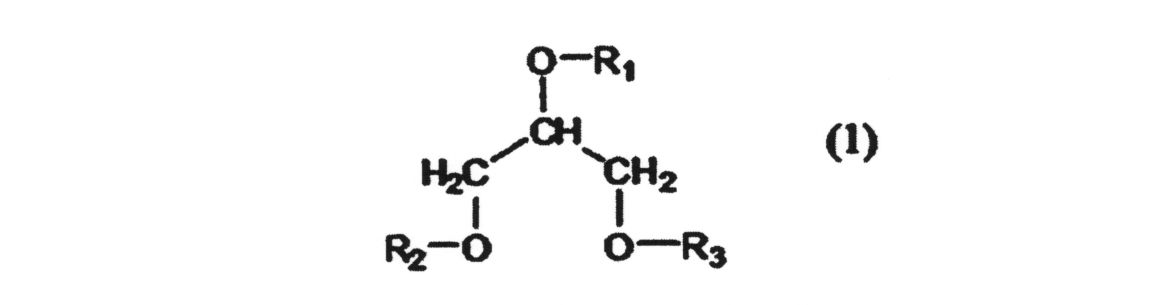
一般式(1)において、R1、R2、R3は、各々独立に、H(水素原子)または下記の一般式(2)で表される基である。

式(2)において、nは1~5の整数を表し、Xは、置換基を有してもよい1,2-フェニレン基、1,2-ナフチレン基、2,3-ナフチレン基、2,3-アントラキノンジイル基、および2,3-アントラセンジイル基から成る群から選ばれるアリーレン基を表し、Yは炭素原子数2~6のアルキレン基を表す)で表される基を表す。
但し、R1、R2、R3のうち少なくとも一つは、一般式(2)で表される基を表す。
但し、R1、R2、R3のうち少なくとも一つは、一般式(2)で表される基を表す。
一般式(1)において、R1、R2、R3の少なくとも1つは一般式(2)で表される基である必要がある。中でも、R1、R2、R3全てが一般式(2)で表される基であることが好ましい。
また、R1、R2、R3のいずれか1つが一般式(2)で表される基である化合物と、R1、R2、R3のいずれか2つが一般式(2)で表される基である化合物と、R1、R2、R3の全てが一般式(2)で表される基である化合物の、いずれか2つ以上の化合物が混合物となっていてもよい。
Xは、1,2-フェニレン基、1,2-ナフチレン基、2,3-ナフチレン基、2,3-アントラキノンジイル基および2,3-アントラセンジイル基から成る群から選ばれ、置換基を有していてもよいアリーレン基を表す。
Xが置換基によって置換されている場合、1または複数の置換基で置換されていてもよく、該置換基は、X上の、遊離基とは異なる任意の炭素原子に結合している。該置換基としては、クロロ基、ブロモ基、メチル基、エチル基、i-プロピル基、ヒドロキシル基、メトキシ基、エトキシ基、フェノキシ基、メチルチオ基、フェニルチオ基、シアノ基、ニトロ基、アミノ基、フタルイミド基、カルボキシル基、カルバモイル基、N-エチルカルバモイル基、フェニル基およびナフチル基などが挙げられる。
Xが置換基によって置換されている場合、1または複数の置換基で置換されていてもよく、該置換基は、X上の、遊離基とは異なる任意の炭素原子に結合している。該置換基としては、クロロ基、ブロモ基、メチル基、エチル基、i-プロピル基、ヒドロキシル基、メトキシ基、エトキシ基、フェノキシ基、メチルチオ基、フェニルチオ基、シアノ基、ニトロ基、アミノ基、フタルイミド基、カルボキシル基、カルバモイル基、N-エチルカルバモイル基、フェニル基およびナフチル基などが挙げられる。
一般式(2)において、Yは、エチレン基、プロピレン基、ブチレン基、ネオペンチレン基、1,5-ペンチレン基、3-メチル-1,5-ペンチレン基、1,6-ヘキシレン基、メチルペンチレン基およびジメチルブチレン基などの炭素原子数2~6のアルキレン基を表す。Yは、中でも、プロピレン基およびエチレン基が好ましくエチレン基が最も好ましい。
一般式(1)で表されるグリセロール骨格を有するポリエステル樹脂化合物は、グリセロールと、カルボン酸がオルト位に置換された芳香族多価カルボン酸またはその無水物と、多価アルコール成分とを必須成分として反応させることにより合成することができる。
カルボン酸がオルト位に置換された芳香族多価カルボン酸またはその無水物としては、オルトフタル酸またはその無水物、ナフタレン2,3-ジカルボン酸またはその無水物、ナフタレン1,2-ジカルボン酸またはその無水物、アントラキノン2,3-ジカルボン酸またはその無水物、および2,3-アントラセンカルボン酸またはその無水物などが挙げられる。
これらの化合物は、芳香環の任意の炭素原子に置換基を有していても良い。該置換基としては、クロロ基、ブロモ基、メチル基、エチル基、i-プロピル基、ヒドロキシル基、メトキシ基、エトキシ基、フェノキシ基、メチルチオ基、フェニルチオ基、シアノ基、ニトロ基、アミノ基、フタルイミド基、カルボキシル基、カルバモイル基、N-エチルカルバモイル基、フェニル基およびナフチル基などが挙げられる。
これらの化合物は、芳香環の任意の炭素原子に置換基を有していても良い。該置換基としては、クロロ基、ブロモ基、メチル基、エチル基、i-プロピル基、ヒドロキシル基、メトキシ基、エトキシ基、フェノキシ基、メチルチオ基、フェニルチオ基、シアノ基、ニトロ基、アミノ基、フタルイミド基、カルボキシル基、カルバモイル基、N-エチルカルバモイル基、フェニル基およびナフチル基などが挙げられる。
また、多価アルコール成分としては炭素原子数2~6のアルキレンジオールが挙げられる。例えば、エチレングリコール、プロピレングリコール、ブチレングリコール、ネオペンチルグリコール、1,5-ペンタンジオール、3-メチル-1,5-ペンタンジオール、1,6-ヘキサンジオール、メチルペンタンジオールおよびジメチルブタンジオールなどのジオールを例示することができる。
第3例に係るポリエステルポリオールは、下記一般式(3)で表されるイソシアヌル環を有するポリエステルポリオールである。
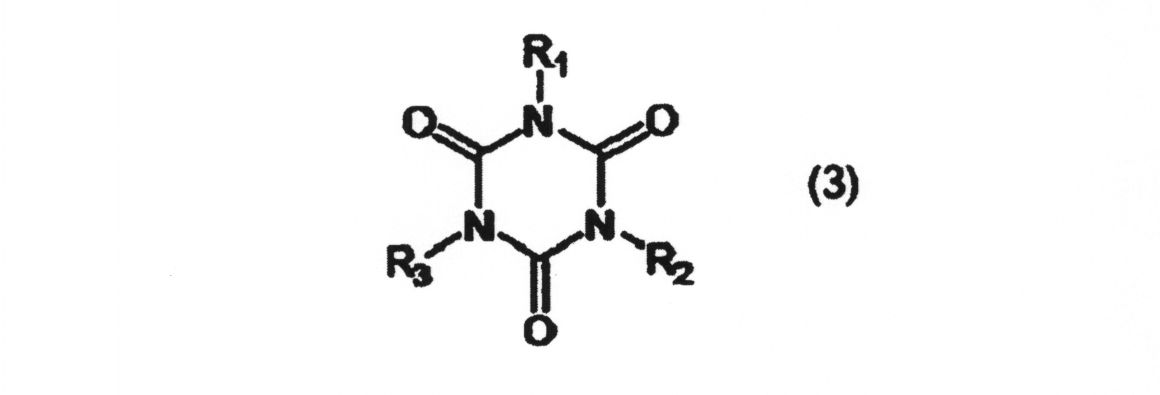
一般式(3)において、R1、R2、R3は、各々独立に、「-(CH2)n1-OH(但しn1は2~4の整数を表す)」、または、一般式(4)の構造を表す。
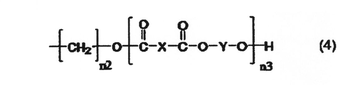
一般式(4)中、n2は2~4の整数を表し、n3は1~5の整数を表し、Xは1,2-フェニレン基、1,2-ナフチレン基、2,3-ナフチレン基、2,3-アントラキノンジイル基および2,3-アントラセンジイル基から成る群から選ばれ、置換基を有していてもよいアリーレン基を表し、Yは炭素原子数2~6のアルキレン基を表す)で表される基を表す。但しR1、R2、R3の少なくとも1つは一般式(4)で表される基である。
一般式(3)において、-(CH2)n1-で表されるアルキレン基は、直鎖状であっても分岐状でもよい。n1は、中でも2または3が好ましく、2が最も好ましい。
一般式(4)において、n2は2~4の整数を表し、n3は1~5の整数を表す。
Xは1,2-フェニレン基、1,2-ナフチレン基、2,3-ナフチレン基、2,3-アントラキノンジイル基、および2,3-アントラセンジイル基から成る群から選ばれ、置換基を有していてもよいアリーレン基を表す。
Xは1,2-フェニレン基、1,2-ナフチレン基、2,3-ナフチレン基、2,3-アントラキノンジイル基、および2,3-アントラセンジイル基から成る群から選ばれ、置換基を有していてもよいアリーレン基を表す。
Xが置換基によって置換されている場合、1または複数の置換基で置換されていてもよく、該置換基は、X上の、遊離基とは異なる任意の炭素原子に結合している。該置換基としては、クロロ基、ブロモ基、メチル基、エチル基、i-プロピル基、ヒドロキシル基、メトキシ基、エトキシ基、フェノキシ基、メチルチオ基、フェニルチオ基、シアノ基、ニトロ基、アミノ基、フタルイミド基、カルボキシル基、カルバモイル基、N-エチルカルバモイル基、フェニル基およびナフチル基などが挙げられる。
Xの置換基は、中でもヒドロキシル基、シアノ基、ニトロ基、アミノ基、フタルイミド基、カルバモイル基、N-エチルカルバモイル基およびフェニル基が好ましくヒドロキシル基、フェノキシ基、シアノ基、ニトロ基、フタルイミド基およびフェニル基が最も好ましい。
Xの置換基は、中でもヒドロキシル基、シアノ基、ニトロ基、アミノ基、フタルイミド基、カルバモイル基、N-エチルカルバモイル基およびフェニル基が好ましくヒドロキシル基、フェノキシ基、シアノ基、ニトロ基、フタルイミド基およびフェニル基が最も好ましい。
一般式(4)において、Yは、エチレン基、プロピレン基、ブチレン基、ネオペンチレン基、1,5-ペンチレン基、3-メチル-1,5-ペンチレン基、1,6-ヘキシレン基、メチルペンチレン基およびジメチルブチレン基などの炭素原子数2~6のアルキレン基を表す。Yは、中でも、プロピレン基およびエチレン基が好ましくエチレン基が最も好ましい。
一般式(3)において、R1、R2、R3の少なくとも1つは一般式(4)で表される基である。中でも、R1、R2、R3全てが一般式(4)で表される基であることが好ましい。
また、R1、R2、R3のいずれか1つが一般式(4)で表される基である化合物と、R1、R2、R3のいずれか2つが一般式(4)で表される基である化合物と、R1、R2、R3の全てが一般式(4)で表される基である化合物の、いずれか2つ以上の化合物が混合物となっていてもよい。
一般式(3)で表されるイソシアヌル環を有するポリエステルポリオールは、イソシアヌル環を有するトリオールと、カルボン酸がオルト位に置換された芳香族多価カルボン酸またはその無水物と、多価アルコール成分とを必須成分として反応させることにより合成することができる
イソシアヌル環を有するトリオールとしては、例えば、1,3,5-トリス(2-ヒドロキシエチル)イソシアヌル酸および1,3,5-トリス(2-ヒドロキシプロピル)イソシアヌル酸などのイソシアヌル酸のアルキレンオキサイド付加物などが挙げられる。
また、カルボン酸がオルト位に置換された芳香族多価カルボン酸またはその無水物としては、オルトフタル酸またはその無水物、ナフタレン2,3-ジカルボン酸またはその無水物、ナフタレン1,2-ジカルボン酸またはその無水物、アントラキノン2,3-ジカルボン酸またはその無水物、および2,3-アントラセンカルボン酸またはその無水物などが挙げられる。これらの化合物は、芳香環の任意の炭素原子に置換基を有していても良い。
該置換基としては、クロロ基、ブロモ基、メチル基、エチル基、i-プロピル基、ヒドロキシル基、メトキシ基、エトキシ基、フェノキシ基、メチルチオ基、フェニルチオ基、シアノ基、ニトロ基、アミノ基、フタルイミド基、カルボキシル基、カルバモイル基、N-エチルカルバモイル基、フェニル基およびナフチル基などが挙げられる。
また、多価アルコール成分としては炭素原子数2~6のアルキレンジオールが挙げられる。例えば、エチレングリコール、プロピレングリコール、ブチレングリコール、ネオペンチルグリコール、1,5-ペンタンジオール、3-メチル-1,5-ペンタンジオール、1,6-ヘキサンジオール、メチルペンタンジオールおよびジメチルブタンジオールなどのジオールが挙げられる。
中でも、イソシアヌル環を有するトリオール化合物として1,3,5-トリス(2-ヒドロキシエチル)イソシアヌル酸、または1,3,5-トリス(2-ヒドロキシプロピル)イソシアヌル酸を使用し、カルボン酸がオルト位に置換された芳香族多価カルボン酸またはその無水物としてオルトフタル酸無水物を使用し、多価アルコールとしてエチレングリコールを使用したイソシアヌル環を有するポリエステルポリオール化合物が、酸素バリア性や接着性に特に優れ好ましい。
中でも、イソシアヌル環を有するトリオール化合物として1,3,5-トリス(2-ヒドロキシエチル)イソシアヌル酸、または1,3,5-トリス(2-ヒドロキシプロピル)イソシアヌル酸を使用し、カルボン酸がオルト位に置換された芳香族多価カルボン酸またはその無水物としてオルトフタル酸無水物を使用し、多価アルコールとしてエチレングリコールを使用したイソシアヌル環を有するポリエステルポリオール化合物が、酸素バリア性や接着性に特に優れ好ましい。
イソシアヌル環は高極性であり且つ3官能であり、系全体の極性を高めることができ、且つ、架橋密度を高めることができる。このような観点からイソシアヌル環を接着剤樹脂全固形分に対し5質量%以上含有することが好ましい。
イソシアネート化合物は、分子内にイソシアネート基を2個以上有する。
また、イソシアネート化合物は、芳香族であっても、脂肪族であってもよく、低分子化合物であっても、高分子化合物であってもよい。
さらに、イソシアネート化合物は、公知のイソシアネートブロック化剤を用いて公知慣用の適宜の方法より付加反応させて得られたブロック化イソシアネート化合物であってもよい。
中でも、接着性や耐レトルト性の観点から、イソシアネート基を3個以上有するポリイソシアネート化合物が好ましく、酸素バリア性および水蒸気バリア性の観点からは、芳香族であることが好ましい。
また、イソシアネート化合物は、芳香族であっても、脂肪族であってもよく、低分子化合物であっても、高分子化合物であってもよい。
さらに、イソシアネート化合物は、公知のイソシアネートブロック化剤を用いて公知慣用の適宜の方法より付加反応させて得られたブロック化イソシアネート化合物であってもよい。
中でも、接着性や耐レトルト性の観点から、イソシアネート基を3個以上有するポリイソシアネート化合物が好ましく、酸素バリア性および水蒸気バリア性の観点からは、芳香族であることが好ましい。
イソシアネート化合物の具体的な化合物としては、例えば、テトラメチレンジイソシアネート、ヘキサメチレンジイソシアネート、トルエンジイソシアネート、ジフェニルメタンジイソシアネート、水素化ジフェニルメタンジイソシアネート、メタキシリレンジイソシアネート、水素化キシリレンジイソシアネート、イソホロンジイソシアネート、およびこれらのイソシアネート化合物の3量体、並びにこれらのイソシアネート化合物と、低分子活性水素化合物若しくはそのアルキレンオキシド付加物、または高分子活性水素化合物とを反応させて得られるアダクト体、ビュレット体およびアロファネート体などが挙げられる。
低分子活性水素化合物としては、例えば、エチレングリコール、プロピレングリコール、メタキシリレンアルコール、1,3-ビスヒドロキシエチルベンゼン、1,4-ビスヒドロキシエチルベンゼン、トリメチロールプロパン、グリセロール、ペンタエリスリトール、エリスリトール、ソルビトール、エチレンジアミン、モノエタノールアミン、ジエタノールアミン、トリエタノールアミンおよびメタキシリレンジアミンなどが挙げられ、分子活性水素化合物としては、各種ポリエステル樹脂、ポリエーテルポリオールおよびポリアミドの高分子活性水素化合物などが挙げられる。
低分子活性水素化合物としては、例えば、エチレングリコール、プロピレングリコール、メタキシリレンアルコール、1,3-ビスヒドロキシエチルベンゼン、1,4-ビスヒドロキシエチルベンゼン、トリメチロールプロパン、グリセロール、ペンタエリスリトール、エリスリトール、ソルビトール、エチレンジアミン、モノエタノールアミン、ジエタノールアミン、トリエタノールアミンおよびメタキシリレンジアミンなどが挙げられ、分子活性水素化合物としては、各種ポリエステル樹脂、ポリエーテルポリオールおよびポリアミドの高分子活性水素化合物などが挙げられる。
リン酸変性化合物は、例えば下記の一般式(5)または(6)で表される化合物である。
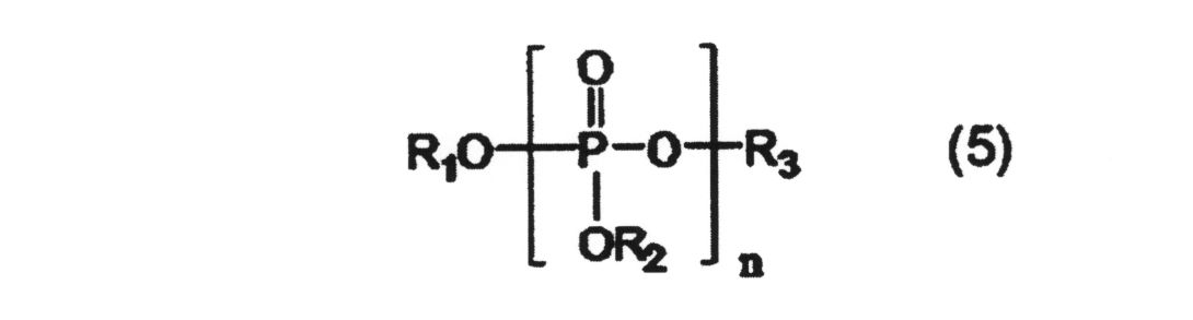
一般式(5)において、R1、R2、R3は、水素原子、炭素数1~30のアルキル基、(メタ)アクリロイル基、置換基を有してもよいフェニル基および(メタ)アクリロイルオキシ基を有する炭素数1~4のアルキル基から選ばれる基であるが、少なくとも一つは水素原子であり、nは、1~4の整数を表す。
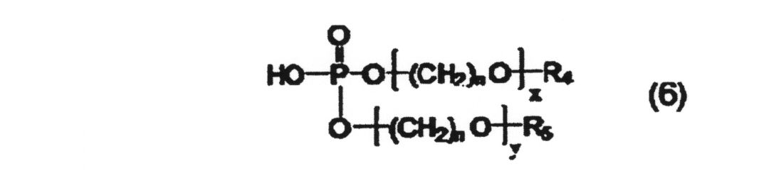
式中、R4、R5は、水素原子、炭素数1~30のアルキル基、(メタ)アクリロイル基、置換基を有してもよいフェニル基および(メタ)アクリロイルオキシ基を有する炭素数1~4のアルキル基から選ばれる基であり、nは1~4の整数、xは0~30の整数、yは0~30の整数を表すが、xとyが共に0である場合を除く。
より具体的には、リン酸、ピロリン酸、トリリン酸、メチルアシッドホスフェート、エチルアシッドホスフェート、ブチルアシッドホスフェート、ジブチルホスフェート、2-エチルヘキシルアシッドホスフェート、ビス(2-エチルヘキシル)ホスフェート、イソドデシルアシッドホスフェート、ブトキシエチルアシッドホスフェート、オレイルアシッドホスフェート、テトラコシルアシッドホスフェート、2-ヒドロキシエチルメタクリレートアシッドホスフェートおよびポリオキシエチレンアルキルエーテルリン酸などが挙げられ、これらの1種または2種以上を用いることができる。
樹脂組成物におけるリン酸変性化合物の含有量は、0.005質量%以上10質量%以下が好ましく、0.01質量%以上1質量%以下であることがより好ましい。
リン酸変性化合物の含有量を0.005質量%以上とすることにより、本発明の積層体の酸素バリア性および水蒸気バリア性を向上することができる。また、リン酸変性化合物の含有量を10質量%以下とすることにより、接着層の接着性を向上することができる。
リン酸変性化合物の含有量を0.005質量%以上とすることにより、本発明の積層体の酸素バリア性および水蒸気バリア性を向上することができる。また、リン酸変性化合物の含有量を10質量%以下とすることにより、接着層の接着性を向上することができる。
ポリエステルポリオール、イソシアネート化合物およびリン酸変性化合物を含有する樹脂組成物は、板状無機化合物を含んでいてもよく、これにより、接着層の接着性を向上することができる。また、本発明の積層体の耐屈曲負荷性を向上させることができる。
板状無機化合物としては、例えば、カオリナイト-蛇紋族粘土鉱物(ハロイサイト、カオリナイト、エンデライト、ディッカイト、ナクライト、アンチゴライト、クリソタイルなど)およびパイロフィライト-タルク族(パイロフィライト、タルク、ケロライなど)などが挙げられる。
板状無機化合物としては、例えば、カオリナイト-蛇紋族粘土鉱物(ハロイサイト、カオリナイト、エンデライト、ディッカイト、ナクライト、アンチゴライト、クリソタイルなど)およびパイロフィライト-タルク族(パイロフィライト、タルク、ケロライなど)などが挙げられる。
カップリング剤としては、例えば、下記一般式(7)であらわされるシラン系カップリング剤、チタン系カップリング剤およびアルミニウム系カップリング剤などが挙げられる。なお、これらのカップリング剤は、単独でも、2種類以上組み合わせてもよい。

シラン系カップリング剤としては、例えば、ビニルトリクロルシラン、ビニルトリメトキシシラン、ビニルトリエトキシシラン、β-(3,4-エポキシシクロヘキシル)エチルトリメトキシシラン、γ-グリシドキシプロピルトリメトキシシラン、γ-グリシドキシプロピルメチルジエトキシシラン、γ-グリシドキシプロピルトリエトキシシラン、γ-メタクリロキシトリメトキシシラン、γ-メタクリロキシプロピルメチルジメトキシシラン、γ-メタクリロキシプロピルトリメトキシシラン、γ-メタクリロキシプロピルメチルジエトキシシラン、γ-メタクリロキシプロピルトリエトキシシラン、N-β(アミノエチル)γ-アミノプロピルメチルジメトキシシラン、N-β(アミノエチル)γ-アミノプロピルトリメトキシシラン、N-β(アミノエチル)γ-アミノプロピルトリエトキシシラン、γ-アミノプロピルトリメトキシシラン、γ-アミノプロピルトリエトキシシラン、N-フェニル-γ-アミノプロピルトリメトキシシラン、γ-クロロプロピルトリメトキシシラン、γ-メルカプトプロピルトリメトキシシラン、3-イソシアネートプロピルトリエトキシシラン、3-アクリロキシプロピルトリメトキシシランおよび3-トリエトキシシリル-N-(1,3-ジメチル-ブチリデン)などが挙げられる。
また、チタン系カップリング剤としては、例えば、イソプロピルトリイソステアロイルチタネート、イソプロピルトリ(N-アミノエチル-アミノエチル)チタネート、イソプロピルトリドデシルベンゼンスルホニルチタネート、イソプロピルトリス(ジオクチルパイロホスフェート)チタネート、テトラオクチルビス(ジドデシルホスファイト)チタネート、テトラオクチルビス(ジトリデシルホスファイト)チタネート、ビス(ジオクチルパイロホスフェート)オキシアセテートチタネート、ビス(ジオクチルパイロホスフェート)エチレンチタネート、イソプロピルトリオクタイノルチタネート、イソプロピルジメタクリルイソステアロイルチタネート、イソプロピルイソステアロイルジアクリルチタネート、ジイソステアロイルエチレンチタネート、イソプロピルトリ(ジオクチルホスフェート)チタネート、イソプロピルトリクミルフェニルチタネートおよびジクミルフェニルオキシアセテートチタネートなどが挙げられる。
また、アルミニウム系カップリング剤の具体例としては、例えば、アセトアルコキシアルミニウムジイソプロピレート、ジイソプロポキシアルミニウムエチルアセトアセテート、ジイソプロポキシアルミニウムモノメタクリレート、イソプロポキシアルミニウムアルキルアセトアセテートモノ(ジオクチルホスフェート)、アルミニウム-2-エチルヘキサノエートオキサイドトリマー、アルミニウムステアレートオキサイドトリマーおよびアルキルアセトアセテートアルミニウムオキサイドトリマーなどが挙げられる。
樹脂組成物は、シクロデキストリンおよび/またはその誘導体を含むことができ、これにより、接着層の接着性を向上することができる。また、本発明の積層体の耐屈曲負荷性をより向上できる。
具体的には、例えば、シクロデキストリン、アルキル化シクロデキストリン、アセチル化シクロデキストリンおよびヒドロキシアルキル化シクロデキストリンなどのシクロデキストリンのグルコース単位の水酸基の水素原子を他の官能基で置換したものなどを用いることができる。また、分岐環状デキストリンも用いることができる。
また、シクロデキストリンおよびシクロデキストリン誘導体におけるシクロデキストリン骨格は、6個のグルコース単位からなるα-シクロデキストリン、7個のグルコース単位からなるβ-シクロデキストリン、8個のグルコース単位からなるγ-シクロデキストリンのいずれであってもよい。
これらの化合物は単独で用いても2種以上を併用してもよい。また、これらシクロデキストリンおよび/またはその誘導体を以降、デキストリン化合物と総称する場合がある。
樹脂組成物への相溶性および分散性の観点から、シクロデキストリン化合物としては、シクロデキストリン誘導体を用いることが好ましい。
アルキル化シクロデキストリンとしては、例えば、メチル-α-シクロデキストリン、メチル-β-シクロデキストリンおよびメチル-γ-シクロデキストリンなどが挙げられる。これらの化合物は単独で用いても2種以上を併用してもよい。
アセチル化シクロデキストリンとしては、例えば、モノアセチル-α-シクロデキストリン、モノアセチル-β-シクロデキストリンおよびモノアセチル-γ-シクロデキストリンなどが挙げられる。これらの化合物は単独で用いても2種以上を併用してもよい。
ヒドロキシアルキル化シクロデキストリンとしては、例えば、ヒドロキシプロピル-α-シクロデキストリン、ヒドロキシプロピル-β-シクロデキストリンおよびヒドロキシプロピル-γ-シクロデキストリンなどが挙げられる。これらの化合物は単独で用いても2種以上を併用してもよい。
接着層の厚さは、0.5μm以上6μm以下であることが好ましく、0.8μm以上5μm以下であることがより好ましく、1μm以上4.5μm以下であることがさらに好ましい。
接着層の厚さを0.5μm以上とすることにより、接着層の接着性を向上することができる。また、ポリエステルポリオールとイソシアネート化合物とリン酸変性化合物を含む樹脂組成物の硬化物からなる接着層を、アルミニウム蒸着膜と隣接するように設けた場合には、積層体の耐屈曲負荷性を向上することができる。
接着層の厚さを6μm以下とすることにより、積層体の加工適性を向上することができる。
接着層の厚さを0.5μm以上とすることにより、接着層の接着性を向上することができる。また、ポリエステルポリオールとイソシアネート化合物とリン酸変性化合物を含む樹脂組成物の硬化物からなる接着層を、アルミニウム蒸着膜と隣接するように設けた場合には、積層体の耐屈曲負荷性を向上することができる。
接着層の厚さを6μm以下とすることにより、積層体の加工適性を向上することができる。
接着層は、例えば、ダイレクトグラビアロールコート法、グラビアロールコート法、キスコート法、リバースロールコート法、フォンテン法およびトランスファーロールコート法など従来公知の方法により、基材などの上に塗布、乾燥することにより形成することができる。
<用途>
本発明の積層体は、包装材料用途に特に好適に使用することができる。
包装材料としては、特に限定されず、図5に示すように、包装袋110であってもよく、図6に示すように、胴部130および底部140を備えるスタンドパウチ120であってもよい。なお、スタンドパウチにおいては、胴部のみが上記積層体により形成されていても、底部のみが上記積層体により形成されていても、胴部および底部の両方が上記積層体により形成されていてもよい。
本発明の積層体は、包装材料用途に特に好適に使用することができる。
包装材料としては、特に限定されず、図5に示すように、包装袋110であってもよく、図6に示すように、胴部130および底部140を備えるスタンドパウチ120であってもよい。なお、スタンドパウチにおいては、胴部のみが上記積層体により形成されていても、底部のみが上記積層体により形成されていても、胴部および底部の両方が上記積層体により形成されていてもよい。
包装袋は、上記積層体のヒートシール層が内側となるように、二つ折にして重ね合わせて、その端部をヒートシールすることにより製造することができる。
また、包装袋は、2枚の積層体を、ヒートシール層が向かい合うように重ね合わせ、その端部をヒートシールすることによっても製造することができる。
また、包装袋は、2枚の積層体を、ヒートシール層が向かい合うように重ね合わせ、その端部をヒートシールすることによっても製造することができる。
スタンドパウチは、上記積層体のヒートシール層が内側となるように、筒状にヒートシールすることにより、胴部を形成し、次いで、ヒートシール層が内側となるように、上記積層体をV字状に折り、胴部の一端から挟み込み、ヒートシールすることにより底部を形成し、製造することができる。
ヒートシールの方法は、特に限定されるものではなく、例えば、バーシール、回転ロールシール、ベルトシール、インパルスシール、高周波シール、超音波シールなどの公知の方法で行うことができる。
包装材料に充填される内容物は、特に限定されるものではなく、内容物は、液体、粉体およびゲル体であってもよい。また、食品であっても、非食品であってもよい。
内容物充填後、開口をヒートシールすることにより、包装体とすることができる。
内容物充填後、開口をヒートシールすることにより、包装体とすることができる。
本発明について実施例を挙げてさらに具体的に説明するが、本発明がこれら実施例によって限定されるものではない。
<実施例1-1>
中密度ポリエチレン(密度:0.941g/cm3、融点129℃、MFR:1.3g/10分、Dowchemical社製、商品名:Elite5538G)をインフレーション成形法により製膜し、厚さ100μmのポリエチレンフィルムを得た。
このポリエチレンフィルムを長手方向(MD)に、5倍の延伸倍率で延伸し、厚さ20μmの延伸ポリエチレンフィルム(基材)を得た。延伸ポリエチレンフィルムのヘイズ値をJIS K-7105に準拠し、測定したところ、6.5%であった。
中密度ポリエチレン(密度:0.941g/cm3、融点129℃、MFR:1.3g/10分、Dowchemical社製、商品名:Elite5538G)をインフレーション成形法により製膜し、厚さ100μmのポリエチレンフィルムを得た。
このポリエチレンフィルムを長手方向(MD)に、5倍の延伸倍率で延伸し、厚さ20μmの延伸ポリエチレンフィルム(基材)を得た。延伸ポリエチレンフィルムのヘイズ値をJIS K-7105に準拠し、測定したところ、6.5%であった。
上記延伸ポリエチレンフィルムと、厚さ40μmの、未延伸直鎖状低密度ポリエチレン(LLDPE)フィルム(東洋紡(株)製、商品名:L6100、ヒートシール層)とを、2液硬化型ウレタン系接着剤(ロックペイント(株)製、商品名:RU-77T/H-7)を介して積層し、本発明の積層体を得た。
<実施例1-2>
高密度ポリエチレン(密度:0.961g/cm3、融点135℃、MFR:0.7g/10分、ExxonMobil社製、商品名:HTA108)及び中密度ポリエチレン(密度:0.941g/cm3、融点129℃、MFR:1.3g/10分、Dowchemical社製、商品名:Elite5538G)を、インフレーション成形法により製膜し、高密度ポリエチレン層と、中密度ポリエチレン層と、高密度ポリエチレン層とからなるポリエチレンフィルムを作製した。高密度ポリエチレン層の厚さは、それぞれ20μm、中密度ポリエチレン層の厚さは、60μmであった。
このポリエチレンフィルムを長手方向(MD)に、5倍の延伸倍率で延伸し、厚さ20μmの延伸ポリエチレンフィルム(基材)を得た。延伸ポリエチレンフィルムのヘイズ値は8.9%であった。
上記延伸ポリエチレンフィルムと、厚さ40μmの、未延伸直鎖状低密度ポリエチレン(LLDPE)フィルム(東洋紡(株)製、商品名:L6100、ヒートシール層)とを、2液硬化型ウレタン系接着剤(ロックペイント(株)製、商品名:RU-77T/H-7)を介して積層し、本発明の積層体を得た。
<実施例1-3>
中密度ポリエチレン(密度:0.941g/cm3、融点129℃、MFR:1.3g/10分、Dowchemical社製、商品名:Elite5538G)をインフレーション成形法により製膜し、厚さ100μmのポリエチレンフィルムを得た。
このポリエチレンフィルムを長手方向(MD)及び幅方向(TD)に、2.24倍の延伸倍率で延伸し、厚さ20μmの延伸ポリエチレンフィルム(基材)を得た。延伸ポリエチレンフィルムのヘイズ値をJIS K-7105に準拠し、測定したところ、5.1%であった。
中密度ポリエチレン(密度:0.941g/cm3、融点129℃、MFR:1.3g/10分、Dowchemical社製、商品名:Elite5538G)をインフレーション成形法により製膜し、厚さ100μmのポリエチレンフィルムを得た。
このポリエチレンフィルムを長手方向(MD)及び幅方向(TD)に、2.24倍の延伸倍率で延伸し、厚さ20μmの延伸ポリエチレンフィルム(基材)を得た。延伸ポリエチレンフィルムのヘイズ値をJIS K-7105に準拠し、測定したところ、5.1%であった。
上記延伸ポリエチレンフィルムと、厚さ40μmの、未延伸直鎖状低密度ポリエチレン(LLDPE)フィルム(東洋紡(株)製、商品名:L6100、ヒートシール層)とを、2液硬化型ウレタン系接着剤(ロックペイント(株)製、商品名:RU-77T/H-7)を介して積層し、本発明の積層体を得た。
<比較例1-1>
中密度ポリエチレン(密度:0.941g/cm3、融点129℃、MFR:1.3g/10分、Dowchemical社製、商品名:Elite5538G)をインフレーション成形法により製膜し、厚さ20μmのポリエチレンフィルム(基材)を得た。ポリエチレンフィルムのヘイズ値をJIS K-7105に準拠し、測定したところ、23.5%であった。
中密度ポリエチレン(密度:0.941g/cm3、融点129℃、MFR:1.3g/10分、Dowchemical社製、商品名:Elite5538G)をインフレーション成形法により製膜し、厚さ20μmのポリエチレンフィルム(基材)を得た。ポリエチレンフィルムのヘイズ値をJIS K-7105に準拠し、測定したところ、23.5%であった。
上記ポリエチレンフィルムと、厚さ40μmの、未延伸直鎖状低密度ポリエチレン(LLDPE)フィルム(東洋紡(株)製、商品名:L6100、ヒートシール層)とを、2液硬化型ウレタン系接着剤(ロックペイント(株)製、商品名:RU-77T/H-7)を介して積層し、積層体を得た。
<比較例1-2>
高密度ポリエチレン(密度:0.961g/cm3、融点135℃、MFR:0.7g/10分、ExxonMobil社製、商品名:HTA108)及び中密度ポリエチレン(密度:0.941g/cm3、融点129℃、MFR:1.3g/10分、Dowchemical社製、商品名:Elite5538G)を、インフレーション成形法により製膜し、高密度ポリエチレン層と、中密度ポリエチレン層と、高密度ポリエチレン層からなるポリエチレンフィルム(基材)を作製した。高密度ポリエチレン層の厚さは、それぞれ4μm、中密度ポリエチレン層の厚さは、12μmであった。ポリエチレンフィルムのヘイズ値をJIS K-7105に準拠し、測定したところ、28.8%であった。
高密度ポリエチレン(密度:0.961g/cm3、融点135℃、MFR:0.7g/10分、ExxonMobil社製、商品名:HTA108)及び中密度ポリエチレン(密度:0.941g/cm3、融点129℃、MFR:1.3g/10分、Dowchemical社製、商品名:Elite5538G)を、インフレーション成形法により製膜し、高密度ポリエチレン層と、中密度ポリエチレン層と、高密度ポリエチレン層からなるポリエチレンフィルム(基材)を作製した。高密度ポリエチレン層の厚さは、それぞれ4μm、中密度ポリエチレン層の厚さは、12μmであった。ポリエチレンフィルムのヘイズ値をJIS K-7105に準拠し、測定したところ、28.8%であった。
上記ポリエチレンフィルムと、厚さ40μmの、未延伸直鎖状低密度ポリエチレン(LLDPE)フィルム(東洋紡(株)製、商品名:L6100、ヒートシール層)とを、2液硬化型ウレタン系接着剤(ロックペイント(株)製、商品名:RU-77T/H-7)を介して積層し、積層体を得た。
<印刷適性評価>
上記実施例及び比較例において作製した延伸ポリエチレンフィルム及びポリエチレンフィルムの一方の面に、水性フレキソインキ(東洋インキ(株)製、商品名:アクワリオナ)を用いて、フレキソ印刷法により、画像を形成した。形成した画像を目視により観察し、延伸ポリエチレンフィルム及びポリエチレンフィルムの印刷適性を以下の評価基準に基づいて、評価した。評価結果を表1にまとめた。
(評価基準)
○:印刷時の寸法安定性が良好であり、擦れ、滲み等が生じていない良好な画像を形成することができていた。
×:印刷時にフィルムの伸び縮みが発生し、形成した画像に擦れや滲みが生じていた。
上記実施例及び比較例において作製した延伸ポリエチレンフィルム及びポリエチレンフィルムの一方の面に、水性フレキソインキ(東洋インキ(株)製、商品名:アクワリオナ)を用いて、フレキソ印刷法により、画像を形成した。形成した画像を目視により観察し、延伸ポリエチレンフィルム及びポリエチレンフィルムの印刷適性を以下の評価基準に基づいて、評価した。評価結果を表1にまとめた。
(評価基準)
○:印刷時の寸法安定性が良好であり、擦れ、滲み等が生じていない良好な画像を形成することができていた。
×:印刷時にフィルムの伸び縮みが発生し、形成した画像に擦れや滲みが生じていた。
<剛性評価>
上記実施例及び比較例において作製した延伸ポリエチレンフィルム及びポリエチレンフィルムを、15mm幅の試験片とし、ループスティフネス測定試験器(東洋精機製作所製、商品名:ループステフネステスタ)によりその剛性を測定した。なお、ループの長さは、60mmとした。測定結果を表1にまとめた。
上記実施例及び比較例において作製した延伸ポリエチレンフィルム及びポリエチレンフィルムを、15mm幅の試験片とし、ループスティフネス測定試験器(東洋精機製作所製、商品名:ループステフネステスタ)によりその剛性を測定した。なお、ループの長さは、60mmとした。測定結果を表1にまとめた。
<強度評価>
上記実施例及び比較例において作製した延伸ポリエチレンフィルム及びポリエチレンフィルムを、10mm幅のダンベル型試験片とした。この試験片のMD方向の引っ張り強度を、引っ張り試験機(オリエンテック社製、RTC-1310A)により測定した。なお、チャック間距離は、10mm、引っ張り速度は、300mm/分とした。測定結果を表1にまとめた。
上記実施例及び比較例において作製した延伸ポリエチレンフィルム及びポリエチレンフィルムを、10mm幅のダンベル型試験片とした。この試験片のMD方向の引っ張り強度を、引っ張り試験機(オリエンテック社製、RTC-1310A)により測定した。なお、チャック間距離は、10mm、引っ張り速度は、300mm/分とした。測定結果を表1にまとめた。
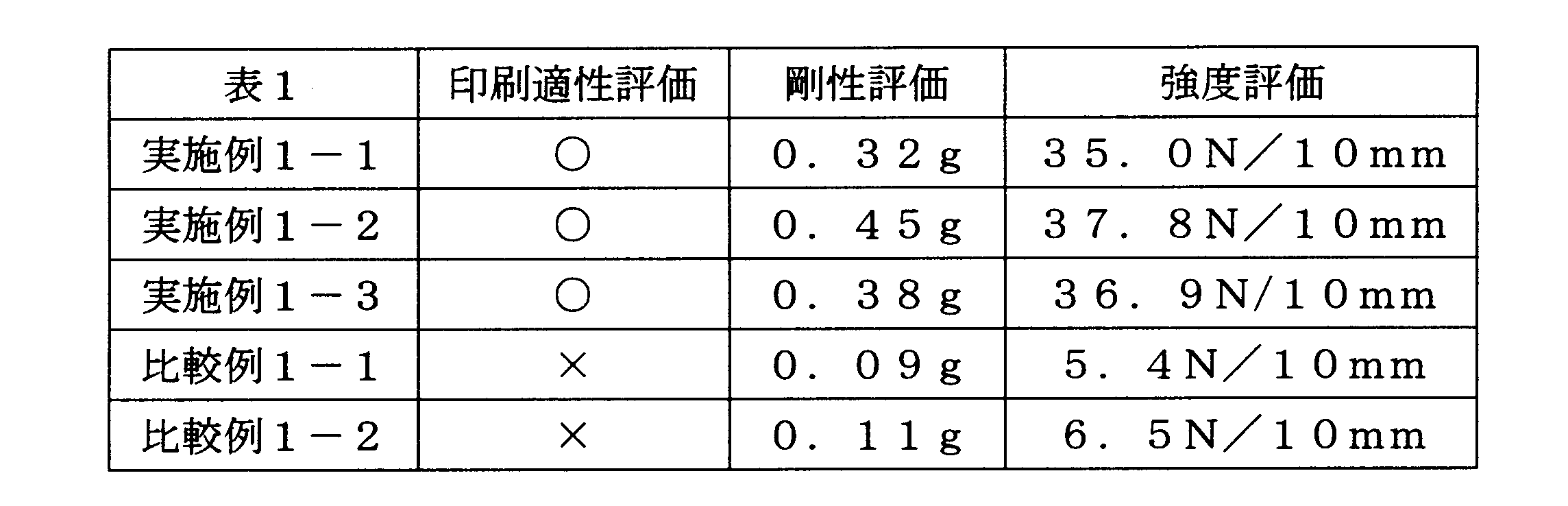
<実施例2-1>
中密度ポリエチレン(密度:0.941g/cm3、融点129℃、MFR:1.3g/10分、Dowchemical社製、商品名:Elite5538G)をインフレーション成形法により製膜し、厚さ100μmのポリエチレンフィルムを得た。
このポリエチレンフィルムを長手方向(MD)に、5倍の延伸倍率で延伸し、厚さ20μmの延伸ポリエチレンフィルム(基材)を得た。
中密度ポリエチレン(密度:0.941g/cm3、融点129℃、MFR:1.3g/10分、Dowchemical社製、商品名:Elite5538G)をインフレーション成形法により製膜し、厚さ100μmのポリエチレンフィルムを得た。
このポリエチレンフィルムを長手方向(MD)に、5倍の延伸倍率で延伸し、厚さ20μmの延伸ポリエチレンフィルム(基材)を得た。
延伸ポリエチレンフィルムの一方の面に、真空蒸着法により、厚さ0.1μmの酸化アルミニウムからなる蒸着膜を形成させた。
延伸ポリエチレンフィルムの蒸着面に、厚さ40μmの、未延伸直鎖状低密度ポリエチレン(LLDPE)フィルム(東洋紡(株)製、商品名:L6100、ヒートシール層)を、2液硬化型ウレタン系接着剤(ロックペイント(株)製、商品名:RU-77T/H-7)を介して積層し、本発明の積層体を得た。
<実施例2-2>
高密度ポリエチレン(密度:0.961g/cm3、融点135℃、MFR:0.7g/10分、ExxonMobil社製、商品名:HTA108)及び中密度ポリエチレン(密度:0.941g/cm3、融点129℃、MFR:1.3g/10分、Dowchemical社製、商品名:Elite5538G)を、インフレーション成形法により製膜し、高密度ポリエチレン層と、中密度ポリエチレン層と、高密度ポリエチレン層からなるポリエチレンフィルムを作製した。高密度ポリエチレン層の厚さは、それぞれ20μm、中密度ポリエチレン層の厚さは、60μmであった。
このポリエチレンフィルムを長手方向(MD)に、5倍の延伸倍率で延伸し、厚さ20μmの延伸ポリエチレンフィルム(基材)を得た。
延伸ポリエチレンフィルムの一方の面に、真空蒸着法により、厚さ0.1μmの酸化アルミニウムからなる蒸着膜を形成させた。
延伸ポリエチレンフィルムの非蒸着面に、厚さ40μmの、未延伸直鎖状低密度ポリエチレン(LLDPE)フィルム(東洋紡(株)製、商品名:L6100、ヒートシール層)を、2液硬化型ウレタン系接着剤(ロックペイント(株)製、商品名:RU-77T/H-7)を介して積層し、本発明の積層体を得た。
<実施例2-3>
中密度ポリエチレン(密度:0.941g/cm3、融点129℃、MFR:1.3g/10分、Dowchemical社製、商品名:Elite5538G)をインフレーション成形法により製膜し、厚さ100μmのポリエチレンフィルムを2枚得た。
2枚のポリエチレンフィルムを長手方向(MD)に、5倍の延伸倍率で延伸し、厚さ20μmの延伸ポリエチレンフィルムを得た。
中密度ポリエチレン(密度:0.941g/cm3、融点129℃、MFR:1.3g/10分、Dowchemical社製、商品名:Elite5538G)をインフレーション成形法により製膜し、厚さ100μmのポリエチレンフィルムを2枚得た。
2枚のポリエチレンフィルムを長手方向(MD)に、5倍の延伸倍率で延伸し、厚さ20μmの延伸ポリエチレンフィルムを得た。
1枚の延伸ポリエチレンフィルムの一方の面に、真空蒸着法により、厚さ0.1μmのアルミニウムからなる蒸着膜を形成させた(中間層)。
次いで、この蒸着膜を備える延伸ポリエチレンフィルムの蒸着面に、もう1枚の延伸ポリエチレンフィルム(基材)を、2液硬化型ウレタン系接着剤(ロックペイント(株)製、商品名:RU-77T/H-7)を介して積層した。
蒸着膜を備える延伸ポリエチレンフィルムの非蒸着面に、厚さ40μmの、未延伸直鎖状低密度ポリエチレン(LLDPE)フィルム(東洋紡(株)製、商品名:L6100)を、2液硬化型ウレタン系接着剤(ロックペイント(株)製、商品名:RU-77T/H-7、ヒートシール層)を介して積層し、本発明の積層体を得た。
<実施例2-4>
中密度ポリエチレン(密度:0.941g/cm3、融点129℃、MFR:1.3g/10分、Dowchemical社製、商品名:Elite5538G)をインフレーション成形法により製膜し、厚さ100μmのポリエチレンフィルムを得た。
このポリエチレンフィルムを長手方向(MD)に、2.24倍の延伸倍率で延伸し、幅方向(TD)に、2.24倍の延伸倍率で延伸し、厚さ20μmの延伸ポリエチレンフィルム(基材)を得た。
中密度ポリエチレン(密度:0.941g/cm3、融点129℃、MFR:1.3g/10分、Dowchemical社製、商品名:Elite5538G)をインフレーション成形法により製膜し、厚さ100μmのポリエチレンフィルムを得た。
このポリエチレンフィルムを長手方向(MD)に、2.24倍の延伸倍率で延伸し、幅方向(TD)に、2.24倍の延伸倍率で延伸し、厚さ20μmの延伸ポリエチレンフィルム(基材)を得た。
延伸ポリエチレンフィルムの一方の面に、真空蒸着法により、厚さ0.1μmの酸化アルミニウムからなる蒸着膜を形成させた。
延伸ポリエチレンフィルムの蒸着面に、厚さ40μmの、未延伸直鎖状低密度ポリエチレン(LLDPE)フィルム(東洋紡(株)製、商品名:L6100、ヒートシール層)を、2液硬化型ウレタン系接着剤(ロックペイント(株)製、商品名:RU-77T/H-7)を介して積層し、本発明の積層体を得た。
<比較例2-1>
中密度ポリエチレン(密度:0.941g/cm3、融点129℃、MFR:1.3g/10分、Dowchemical社製、商品名:Elite5538G)をインフレーション成形法により製膜し、厚さ20μmのポリエチレンフィルム(基材)を得た。
中密度ポリエチレン(密度:0.941g/cm3、融点129℃、MFR:1.3g/10分、Dowchemical社製、商品名:Elite5538G)をインフレーション成形法により製膜し、厚さ20μmのポリエチレンフィルム(基材)を得た。
ポリエチレンフィルムの一方の面に、真空蒸着法により、厚さ0.1μmの酸化アルミニウムからなる蒸着膜を形成させた。
ポリエチレンフィルムの非蒸着面に、厚さ40μmの、未延伸直鎖状低密度ポリエチレン(LLDPE)フィルム(東洋紡(株)製、商品名:L6100、ヒートシール層)を、2液硬化型ウレタン系接着剤(ロックペイント(株)製、商品名:RU-77T/H-7)を介して積層し、積層体を得た。
<比較例2-2>
高密度ポリエチレン(密度:0.961g/cm3、融点135℃、MFR:0.7g/10分、ExxonMobil社製、商品名:HTA108)及び中密度ポリエチレン(密度:0.941g/cm3、融点129℃、MFR:1.3g/10分、Dowchemical社製、商品名:Elite5538G)を、インフレーション成形法により製膜し、高密度ポリエチレン層と、中密度ポリエチレン層と、高密度ポリエチレン層とからなるポリエチレンフィルム(基材)を作製した。高密度ポリエチレン層の厚さは、それぞれ4μm、中密度ポリエチレン層の厚さは、12μmであった。
高密度ポリエチレン(密度:0.961g/cm3、融点135℃、MFR:0.7g/10分、ExxonMobil社製、商品名:HTA108)及び中密度ポリエチレン(密度:0.941g/cm3、融点129℃、MFR:1.3g/10分、Dowchemical社製、商品名:Elite5538G)を、インフレーション成形法により製膜し、高密度ポリエチレン層と、中密度ポリエチレン層と、高密度ポリエチレン層とからなるポリエチレンフィルム(基材)を作製した。高密度ポリエチレン層の厚さは、それぞれ4μm、中密度ポリエチレン層の厚さは、12μmであった。
ポリエチレンフィルムの一方の面に、真空蒸着法により、厚さ0.1μmの酸化アルミニウムからなる蒸着膜を形成させた。
ポリエチレンフィルムの非蒸着面に、厚さ40μmの、未延伸直鎖状低密度ポリエチレン(LLDPE)フィルム(東洋紡(株)製、商品名:L6100、ヒートシール層)を、2液硬化型ウレタン系接着剤(ロックペイント(株)製、商品名:RU-77T/H-7)を介して積層し、積層体を得た。
<比較例2-3>
中密度ポリエチレン(密度:0.941g/cm3、融点129℃、MFR:1.3g/10分、Dowchemical社製、商品名:Elite5538G)をインフレーション成形法により製膜し、厚さ20μmのポリエチレンフィルムを2枚得た。
中密度ポリエチレン(密度:0.941g/cm3、融点129℃、MFR:1.3g/10分、Dowchemical社製、商品名:Elite5538G)をインフレーション成形法により製膜し、厚さ20μmのポリエチレンフィルムを2枚得た。
1枚のポリエチレンフィルムの一方の面に、真空蒸着法により、厚さ0.1μmのアルミニウムからなる蒸着膜を形成させた。
次いで、この蒸着膜を備えるポリエチレンフィルムの蒸着面に、もう1枚のポリエチレンフィルムを、2液硬化型ウレタン系接着剤(ロックペイント(株)製、商品名:RU-77T/H-7)を介して積層した。
蒸着膜を備えるポリエチレンフィルムの非蒸着面に、厚さ40μmの、未延伸直鎖状低密度ポリエチレン(LLDPE)フィルム(東洋紡(株)製、商品名:L6100)を、2液硬化型ウレタン系接着剤(ロックペイント(株)製、商品名:RU-77T/H-7)を介して積層し、積層体を得た。
<印刷適性評価>
上記実施例及び比較例において作製した延伸ポリエチレンフィルム及びポリエチレンフィルムの一方の面に、水性フレキソインキ(東洋インキ(株)製、商品名:アクワリオナ)を用いて、フレキソ印刷法により、画像を形成した。形成した画像を目視により観察し、延伸ポリエチレンフィルム及びポリエチレンフィルムの印刷適性を以下の評価基準に基づいて、評価した。評価結果を表2にまとめた。
(評価基準)
○:印刷時の寸法安定性が良好であり、擦れ、滲み等が生じていない良好な画像を形成することができていた。
×:印刷時にフィルムの伸び縮みが発生し、形成した画像に擦れや滲みが生じていた。
上記実施例及び比較例において作製した延伸ポリエチレンフィルム及びポリエチレンフィルムの一方の面に、水性フレキソインキ(東洋インキ(株)製、商品名:アクワリオナ)を用いて、フレキソ印刷法により、画像を形成した。形成した画像を目視により観察し、延伸ポリエチレンフィルム及びポリエチレンフィルムの印刷適性を以下の評価基準に基づいて、評価した。評価結果を表2にまとめた。
(評価基準)
○:印刷時の寸法安定性が良好であり、擦れ、滲み等が生じていない良好な画像を形成することができていた。
×:印刷時にフィルムの伸び縮みが発生し、形成した画像に擦れや滲みが生じていた。
<剛性評価>
上記実施例及び比較例において作製した延伸ポリエチレンフィルム及びポリエチレンフィルムを、15mm幅の試験片とし、ループスティフネス測定試験器(東洋精機製作所製、商品名:ループステフネステスタ)によりその剛性を測定した。なお、ループの長さは、60mmとした。測定結果を表2にまとめた。
上記実施例及び比較例において作製した延伸ポリエチレンフィルム及びポリエチレンフィルムを、15mm幅の試験片とし、ループスティフネス測定試験器(東洋精機製作所製、商品名:ループステフネステスタ)によりその剛性を測定した。なお、ループの長さは、60mmとした。測定結果を表2にまとめた。
<強度評価>
上記実施例及び比較例において作製した延伸ポリエチレンフィルム及びポリエチレンフィルムを、10mm幅のダンベル型試験片とした。この試験片のMD方向の引っ張り強度を、引っ張り試験機(オリエンテック社製、RTC-1310A)により測定した。なお、チャック間距離は、10mm、引っ張り速度は、300mm/分とした。測定結果を表2にまとめた。
上記実施例及び比較例において作製した延伸ポリエチレンフィルム及びポリエチレンフィルムを、10mm幅のダンベル型試験片とした。この試験片のMD方向の引っ張り強度を、引っ張り試験機(オリエンテック社製、RTC-1310A)により測定した。なお、チャック間距離は、10mm、引っ張り速度は、300mm/分とした。測定結果を表2にまとめた。
<ガスバリア性評価>
上記実施例及び比較例において作製した積層体の水蒸気透過率(g/m2・day)を米国MOCON社製の水蒸気透過率測定装置(PERMATRAN)を使用して測定した。測定結果を表2にまとめた。
上記実施例及び比較例において作製した積層体の水蒸気透過率(g/m2・day)を米国MOCON社製の水蒸気透過率測定装置(PERMATRAN)を使用して測定した。測定結果を表2にまとめた。
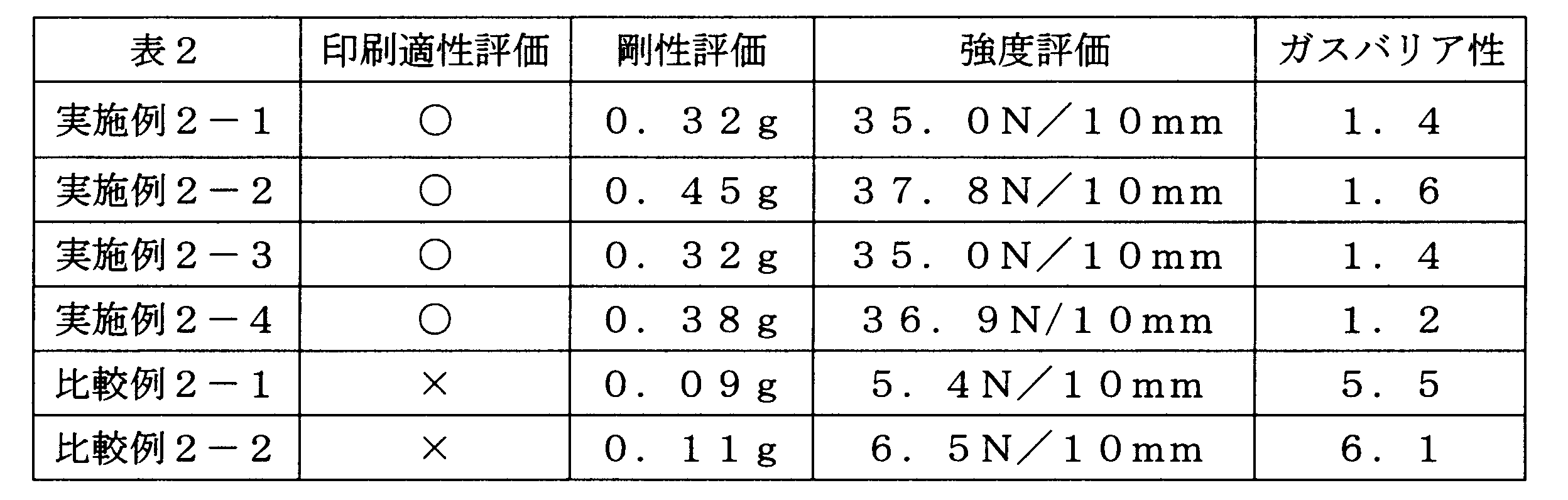
<実施例3-1>
中密度ポリエチレン(密度:0.941g/cm3、融点129℃、MFR:1.3g/10分、Dowchemical社製、商品名:Elite5538G)をインフレーション成形法により製膜し、厚さ100μmのポリエチレンフィルムを得た。
このポリエチレンフィルムを長手方向(MD)に、5倍の延伸倍率で延伸し、厚さ20μmの延伸ポリエチレンフィルム(基材)を得た。
中密度ポリエチレン(密度:0.941g/cm3、融点129℃、MFR:1.3g/10分、Dowchemical社製、商品名:Elite5538G)をインフレーション成形法により製膜し、厚さ100μmのポリエチレンフィルムを得た。
このポリエチレンフィルムを長手方向(MD)に、5倍の延伸倍率で延伸し、厚さ20μmの延伸ポリエチレンフィルム(基材)を得た。
上記延伸ポリエチレンフィルムと、厚さ40μmの、未延伸直鎖状低密度ポリエチレン(LLDPE)フィルム(東洋紡(株)製、商品名:L6100、ヒートシール層)とを、2液硬化無溶剤型ポリエステル系接着剤(ロックペイント(株)製、商品名RN-920/HN:920)を介して積層し、本発明の積層体を得た。
<実施例3-2>
高密度ポリエチレン(密度:0.961g/cm3、融点135℃、MFR:0.7g/10分、ExxonMobil社製、商品名:HTA108)及び中密度ポリエチレン(密度:0.941g/cm3、融点129℃、MFR:1.3g/10分、Dowchemical社製、商品名:Elite5538G)を、インフレーション成形法により製膜し、高密度ポリエチレン層と、中密度ポリエチレン層と、高密度ポリエチレン層からなるポリエチレンフィルム(基材)を作製した。高密度ポリエチレン層の厚さは、それぞれ20μm、中密度ポリエチレン層の厚さは、60μmであった。
このポリエチレンフィルムを長手方向(MD)に、5倍の延伸倍率で延伸し、厚さ20μmの延伸ポリエチレンフィルムを得た。
上記延伸ポリエチレンフィルムと、厚さ40μmの、未延伸直鎖状低密度ポリエチレン(LLDPE)フィルム(東洋紡(株)製、商品名:L6100、ヒートシール層)とを、2液硬化無溶剤型ポリエステル系接着剤(ロックペイント(株)製、商品名RN-920/HN:920)を介して積層し、本発明の積層体を得た。
<実施例3-3>
中密度ポリエチレン(密度:0.941g/cm3、融点129℃、MFR:1.3g/10分、Dowchemical社製、商品名:Elite5538G)をインフレーション成形法により製膜し、厚さ100μmのポリエチレンフィルムを得た。
このポリエチレンフィルムを長手方向(MD)及び幅方向(TD)に、2.24倍の延伸倍率で延伸し、厚さ20μmの延伸ポリエチレンフィルム(基材)を得た。
中密度ポリエチレン(密度:0.941g/cm3、融点129℃、MFR:1.3g/10分、Dowchemical社製、商品名:Elite5538G)をインフレーション成形法により製膜し、厚さ100μmのポリエチレンフィルムを得た。
このポリエチレンフィルムを長手方向(MD)及び幅方向(TD)に、2.24倍の延伸倍率で延伸し、厚さ20μmの延伸ポリエチレンフィルム(基材)を得た。
上記延伸ポリエチレンフィルムと、厚さ40μmの、未延伸直鎖状低密度ポリエチレン(LLDPE)フィルム(東洋紡(株)製、商品名:L6100、ヒートシール層)とを、2液硬化無溶剤型ポリエステル系接着剤(ロックペイント(株)製、商品名RN-920/HN:920)を介して積層し、本発明の積層体を得た。
<比較例3-1>
中密度ポリエチレン(密度:0.941g/cm3、融点129℃、MFR:1.3g/10分、Dowchemical社製、商品名:Elite5538G)をインフレーション成形法により製膜し、厚さ20μmのポリエチレンフィルム(基材)を得た。
中密度ポリエチレン(密度:0.941g/cm3、融点129℃、MFR:1.3g/10分、Dowchemical社製、商品名:Elite5538G)をインフレーション成形法により製膜し、厚さ20μmのポリエチレンフィルム(基材)を得た。
上記ポリエチレンフィルムと、厚さ40μmの、未延伸直鎖状低密度ポリエチレン(LLDPE)フィルム(東洋紡(株)製、商品名:L6100、ヒートシール層)とを、2液硬化無溶剤型ポリエステル系接着剤(ロックペイント(株)製、商品名RN-920/HN:920)を介して積層し、積層体を得た。
<比較例3-2>
高密度ポリエチレン(密度:0.961g/cm3、融点135℃、MFR:0.7g/10分、ExxonMobil社製、商品名:HTA108)及び中密度ポリエチレン(密度:0.941g/cm3、融点129℃、MFR:1.3g/10分、Dowchemical社製、商品名:Elite5538G)を、インフレーション成形法により製膜し、高密度ポリエチレン層/中密度ポリエチレン層/高密度ポリエチレン層からなるポリエチレンフィルム(基材)を作製した。高密度ポリエチレン層の厚さは、それぞれ4μm、中密度ポリエチレン層の厚さは、12μmであった。
高密度ポリエチレン(密度:0.961g/cm3、融点135℃、MFR:0.7g/10分、ExxonMobil社製、商品名:HTA108)及び中密度ポリエチレン(密度:0.941g/cm3、融点129℃、MFR:1.3g/10分、Dowchemical社製、商品名:Elite5538G)を、インフレーション成形法により製膜し、高密度ポリエチレン層/中密度ポリエチレン層/高密度ポリエチレン層からなるポリエチレンフィルム(基材)を作製した。高密度ポリエチレン層の厚さは、それぞれ4μm、中密度ポリエチレン層の厚さは、12μmであった。
上記ポリエチレンフィルムと、厚さ40μmの、未延伸直鎖状低密度ポリエチレン(LLDPE)フィルム(東洋紡(株)製、商品名:L6100、ヒートシール層)とを、2液硬化無溶剤型ポリエステル系接着剤(ロックペイント(株)製、商品名RN-920/HN:920)を介して積層し、積層体を得た。
<印刷適性評価>
上記実施例及び比較例において作製した延伸ポリエチレンフィルム及びポリエチレンフィルムの一方の面に、水性フレキソインキ(東洋インキ(株)製、商品名:アクワリオナ)を用いて、フレキソ印刷法により、画像を形成した。形成した画像を目視により観察し、延伸ポリエチレンフィルム及びポリエチレンフィルムの印刷適性を以下の評価基準に基づいて、評価した。評価結果を表3にまとめた。
(評価基準)
○:印刷時の寸法安定性が良好であり、擦れ、滲み等が生じていない良好な画像を形成することができていた。
×:印刷時にフィルムの伸び縮みが発生し、形成した画像に擦れや滲みが生じていた。
上記実施例及び比較例において作製した延伸ポリエチレンフィルム及びポリエチレンフィルムの一方の面に、水性フレキソインキ(東洋インキ(株)製、商品名:アクワリオナ)を用いて、フレキソ印刷法により、画像を形成した。形成した画像を目視により観察し、延伸ポリエチレンフィルム及びポリエチレンフィルムの印刷適性を以下の評価基準に基づいて、評価した。評価結果を表3にまとめた。
(評価基準)
○:印刷時の寸法安定性が良好であり、擦れ、滲み等が生じていない良好な画像を形成することができていた。
×:印刷時にフィルムの伸び縮みが発生し、形成した画像に擦れや滲みが生じていた。
<剛性評価>
上記実施例及び比較例において作製した延伸ポリエチレンフィルム及びポリエチレンフィルムを、15mm幅の試験片とし、ループスティフネス測定試験器(東洋精機製作所製、商品名:ループステフネステスタ)によりその剛性を測定した。なお、ループの長さは、60mmとした。測定結果を表3にまとめた。
上記実施例及び比較例において作製した延伸ポリエチレンフィルム及びポリエチレンフィルムを、15mm幅の試験片とし、ループスティフネス測定試験器(東洋精機製作所製、商品名:ループステフネステスタ)によりその剛性を測定した。なお、ループの長さは、60mmとした。測定結果を表3にまとめた。
<強度評価>
上記実施例及び比較例において作製した延伸ポリエチレンフィルム及びポリエチレンフィルムを、10mm幅のダンベル型試験片とした。この試験片のMD方向の引っ張り強度を、引っ張り試験機(オリエンテック社製、RTC-1310A)により測定した。なお、チャック間距離は、10mm、引っ張り速度は、300mm/分とした。測定結果を表3にまとめた。
上記実施例及び比較例において作製した延伸ポリエチレンフィルム及びポリエチレンフィルムを、10mm幅のダンベル型試験片とした。この試験片のMD方向の引っ張り強度を、引っ張り試験機(オリエンテック社製、RTC-1310A)により測定した。なお、チャック間距離は、10mm、引っ張り速度は、300mm/分とした。測定結果を表3にまとめた。

<実施例4-1>
バイオマス由来の直鎖状低密度ポリエチレン(密度:0.916g/cm3、MFR:1.3g/10分、バイオマス度:87%、Braskem社製、商品名:SLL118)をインフレーション成形法により製膜し、厚さ100μm及び厚さ40μmのポリエチレンフィルムを得た。
厚さ100μmのポリエチレンフィルムを長手方向(MD)に、5倍の延伸倍率で延伸し、厚さ20μmの延伸ポリエチレンフィルム(基材)を得た。
バイオマス由来の直鎖状低密度ポリエチレン(密度:0.916g/cm3、MFR:1.3g/10分、バイオマス度:87%、Braskem社製、商品名:SLL118)をインフレーション成形法により製膜し、厚さ100μm及び厚さ40μmのポリエチレンフィルムを得た。
厚さ100μmのポリエチレンフィルムを長手方向(MD)に、5倍の延伸倍率で延伸し、厚さ20μmの延伸ポリエチレンフィルム(基材)を得た。
延伸後、延伸ポリエチレンフィルム及びポリエチレンフィルムを、2液硬化型ウレタン系接着剤(ロックペイント(株)製、商品名:RU-77T/H-7、ヒートシール層)を介して積層し、本発明の積層体を得た。
<実施例4-2>
バイオマス由来の直鎖状低密度ポリエチレン(密度:0.916g/cm3、MFR:1.3g/10分、バイオマス度:87%、Braskem社製、商品名:SLL118)をインフレーション成形法により製膜し、厚さ100μm及び厚さ40μmのポリエチレンフィルムを得た。
厚さ100μmのポリエチレンフィルムを長手方向(MD)に、2.24倍の延伸倍率で延伸し、幅方向(TD)に2.24倍の延伸倍率で延伸し、厚さ20μmの延伸ポリエチレンフィルム(基材)を得た。
バイオマス由来の直鎖状低密度ポリエチレン(密度:0.916g/cm3、MFR:1.3g/10分、バイオマス度:87%、Braskem社製、商品名:SLL118)をインフレーション成形法により製膜し、厚さ100μm及び厚さ40μmのポリエチレンフィルムを得た。
厚さ100μmのポリエチレンフィルムを長手方向(MD)に、2.24倍の延伸倍率で延伸し、幅方向(TD)に2.24倍の延伸倍率で延伸し、厚さ20μmの延伸ポリエチレンフィルム(基材)を得た。
延伸後、延伸ポリエチレンフィルム及びポリエチレンフィルム(ヒートシール層)を、2液硬化型ウレタン系接着剤(ロックペイント(株)製、商品名:RU-77T/H-7)を介して積層し、本発明の積層体を得た。
<比較例4-1>
バイオマス由来の直鎖状低密度ポリエチレン(密度:0.916g/cm3、MFR:1.3g/10分、バイオマス度:87%、Braskem社製、商品名:SLL118)をインフレーション成形法により製膜し、厚さ20μm及び厚さ40μmのポリエチレンフィルムを得た。
バイオマス由来の直鎖状低密度ポリエチレン(密度:0.916g/cm3、MFR:1.3g/10分、バイオマス度:87%、Braskem社製、商品名:SLL118)をインフレーション成形法により製膜し、厚さ20μm及び厚さ40μmのポリエチレンフィルムを得た。
2枚のポリエチレンフィルムを、2液硬化型ウレタン系接着剤(ロックペイント(株)製、商品名:RU-77T/H-7)を介して積層し、積層体を得た。
<印刷適性評価>
上記実施例及び比較例において作製した延伸ポリエチレンフィルム及びポリエチレンフィルムの一方の面に、水性フレキソインキ(東洋インキ(株)製、商品名:アクワリオナ)を用いて、フレキソ印刷法により、画像を形成した。形成した画像を目視により観察し、延伸ポリエチレンフィルム及びポリエチレンフィルムの印刷適性を以下の評価基準に基づいて、評価した。評価結果を表4にまとめた。
(評価基準)
○:印刷時の寸法安定性が良好であり、擦れ、滲み等が生じていない良好な画像を形成することができていた。
×:印刷時にフィルムの伸び縮みが発生し、形成した画像に擦れや滲みが生じていた。
上記実施例及び比較例において作製した延伸ポリエチレンフィルム及びポリエチレンフィルムの一方の面に、水性フレキソインキ(東洋インキ(株)製、商品名:アクワリオナ)を用いて、フレキソ印刷法により、画像を形成した。形成した画像を目視により観察し、延伸ポリエチレンフィルム及びポリエチレンフィルムの印刷適性を以下の評価基準に基づいて、評価した。評価結果を表4にまとめた。
(評価基準)
○:印刷時の寸法安定性が良好であり、擦れ、滲み等が生じていない良好な画像を形成することができていた。
×:印刷時にフィルムの伸び縮みが発生し、形成した画像に擦れや滲みが生じていた。
<剛性評価>
上記実施例及び比較例において作製した延伸ポリエチレンフィルム及びポリエチレンフィルムを、15mm幅の試験片とし、ループスティフネス測定試験器(東洋精機製作所製、商品名:ループステフネステスタ)によりその剛性を測定した。なお、ループの長さは、60mmとした。測定結果を表4にまとめた。
上記実施例及び比較例において作製した延伸ポリエチレンフィルム及びポリエチレンフィルムを、15mm幅の試験片とし、ループスティフネス測定試験器(東洋精機製作所製、商品名:ループステフネステスタ)によりその剛性を測定した。なお、ループの長さは、60mmとした。測定結果を表4にまとめた。
<強度評価>
上記実施例及び比較例において作製した延伸ポリエチレンフィルム及びポリエチレンフィルムを、10mm幅のダンベル型試験片とした。この試験片のMD方向の引っ張り強度を、引っ張り試験機(オリエンテック社製、RTC-1310A)により測定した。なお、チャック間距離は、10mm、引っ張り速度は、300mm/分とした。測定結果を表4にまとめた。
上記実施例及び比較例において作製した延伸ポリエチレンフィルム及びポリエチレンフィルムを、10mm幅のダンベル型試験片とした。この試験片のMD方向の引っ張り強度を、引っ張り試験機(オリエンテック社製、RTC-1310A)により測定した。なお、チャック間距離は、10mm、引っ張り速度は、300mm/分とした。測定結果を表4にまとめた。
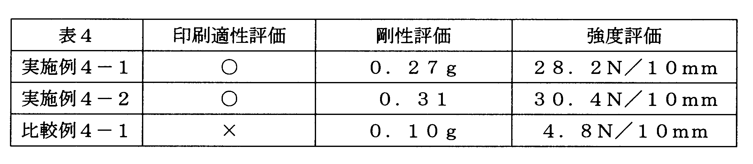
<実施例5-1>
中密度ポリエチレン(密度:0.941g/cm3、融点129℃、MFR:1.3g/10分、Dowchemical社製、商品名:Elite5538G)をインフレーション成形法により製膜し、厚さ100μmのポリエチレンフィルムを得た。
このポリエチレンフィルムを長手方向(MD)に、5倍の延伸倍率で延伸し、厚さ20μmの基材Aを得た。基材Aのヘイズ値を、測定したところ、ヘイズ値は6.5%であった。
中密度ポリエチレン(密度:0.941g/cm3、融点129℃、MFR:1.3g/10分、Dowchemical社製、商品名:Elite5538G)をインフレーション成形法により製膜し、厚さ100μmのポリエチレンフィルムを得た。
このポリエチレンフィルムを長手方向(MD)に、5倍の延伸倍率で延伸し、厚さ20μmの基材Aを得た。基材Aのヘイズ値を、測定したところ、ヘイズ値は6.5%であった。
基材Aの一方の面に、上記水性フレキソインキを用いて、フレキソ印刷法により、画像を形成した。
ヒートシール層として、厚さ40μmの上記未延伸直鎖状低密度ポリエチレンフィルムを準備し、この一方の面に、PVD法により厚さ20nmのアルミニウム蒸着膜を形成した。
基材Aの画像形成面と、ヒートシール層の蒸着面とを、上記2液硬化型ウレタン系接着剤を介して、積層し、本発明の積層体を得た。
なお、2液硬化型ウレタン系接着剤により形成される接着層の厚さは3.0μmであった。
また、このようにして得られた積層体におけるポリエチレンの割合は、94質量%であった。
なお、2液硬化型ウレタン系接着剤により形成される接着層の厚さは3.0μmであった。
また、このようにして得られた積層体におけるポリエチレンの割合は、94質量%であった。
<実施例5-2>
高密度ポリエチレン(密度:0.961g/cm3、融点135℃、MFR:0.7g/10分、ExxonMobil社製、商品名:HTA108)および上記中密度ポリエチレンを、インフレーション成形法により製膜し、高密度ポリエチレン層と、中密度ポリエチレン層と、高密度ポリエチレン層とからなるポリエチレンフィルムを作製した。高密度ポリエチレン層の厚さは、それぞれ20μm、中密度ポリエチレン層の厚さは、60μmであった。
このポリエチレンフィルムを長手方向(MD)に、5倍の延伸倍率で延伸し、高密度ポリエチレン層の厚さがそれぞれ4μm、中密度ポリエチレン層の厚さが12μmである、総厚さ20μmの基材Bを得た。基材Bのヘイズ値を、測定したところ、ヘイズ値は8.9%であった。
基材Bの一方の面に、上記水性フレキソインキを用いて、フレキソ印刷法により、画像を形成した。
ヒートシール層として、厚さ40μmの上記未延伸直鎖状低密度ポリエチレンフィルムを準備し、この一方の面に、PVD法により厚さ20nmのアルミニウム蒸着膜を形成した。
基材Bの画像形成面と、ヒートシール層の蒸着面とを、上記2液硬化型ウレタン系接着剤を介して、積層し、本発明の積層体を得た。
なお、2液硬化型ウレタン系接着剤により形成される接着層の厚さは3.0μmであった。
また、このようにして得られた積層体におけるポリエチレンの割合は、94質量%であった。
なお、2液硬化型ウレタン系接着剤により形成される接着層の厚さは3.0μmであった。
また、このようにして得られた積層体におけるポリエチレンの割合は、94質量%であった。
<実施例5-3>
上記中密度ポリエチレンをインフレーション成形法により製膜し、厚さ100μmのポリエチレンフィルムを得た。
このポリエチレンフィルムを長手方向(MD)および幅方向(TD)に、2.24倍の延伸倍率で延伸し、厚さ20μmの基材Cを得た。基材Cのヘイズ値を、測定したところ、ヘイズ値は5.1%であった。
上記中密度ポリエチレンをインフレーション成形法により製膜し、厚さ100μmのポリエチレンフィルムを得た。
このポリエチレンフィルムを長手方向(MD)および幅方向(TD)に、2.24倍の延伸倍率で延伸し、厚さ20μmの基材Cを得た。基材Cのヘイズ値を、測定したところ、ヘイズ値は5.1%であった。
基材Cの一方の面に、上記水性フレキソインキを用いて、フレキソ印刷法により、画像を形成した。
ヒートシール層として、厚さ40μmの上記未延伸直鎖状低密度ポリエチレンフィルムを準備し、この一方の面に、PVD法により厚さ20nmのアルミニウム蒸着膜を形成した。
基材Cの画像形成面と、ヒートシール層の蒸着膜とを、上記2液硬化型ウレタン系接着剤を介して、積層し、本発明の積層体を得た。
なお、2液硬化型ウレタン系接着剤により形成される接着層の厚さは3.0μmであった。
また、このようにして得られた積層体におけるポリエチレンの割合は、94質量%であった。
なお、2液硬化型ウレタン系接着剤により形成される接着層の厚さは3.0μmであった。
また、このようにして得られた積層体におけるポリエチレンの割合は、94質量%であった。
<実施例5-4>
実施例5-1において、基材Cの画像形成面と、ヒートシール層の蒸着面との接着を、イソシアネート化合物およびリン酸変性化合物を含む2液硬化型接着剤(DIC(株)製、PASLIM VM001/VM102CP)により行った以外は、実施例5-1と同様にして、本発明の積層体を作製した。
実施例5-1において、基材Cの画像形成面と、ヒートシール層の蒸着面との接着を、イソシアネート化合物およびリン酸変性化合物を含む2液硬化型接着剤(DIC(株)製、PASLIM VM001/VM102CP)により行った以外は、実施例5-1と同様にして、本発明の積層体を作製した。
<比較例5-1>
上記中密度ポリエチレンをインフレーション成形法により製膜し、厚さ20μmの基材eを得た。基材aのヘイズ値を、測定したところ、ヘイズ値は23.5%であった。
上記中密度ポリエチレンをインフレーション成形法により製膜し、厚さ20μmの基材eを得た。基材aのヘイズ値を、測定したところ、ヘイズ値は23.5%であった。
基材aの一方の面に、上記水性フレキソインキを用いて、フレキソ印刷法により、画像を形成した。
ヒートシール層として、厚さ40μmの上記未延伸直鎖状低密度ポリエチレンフィルムを準備し、この一方の面に、PVD法により厚さ20nmのアルミニウム蒸着膜を形成した。
基材aの画像形成面と、ヒートシール層の蒸着面とを、上記2液硬化型ウレタン系接着剤を介して、積層し、積層体を得た。
なお、2液硬化型ウレタン系接着剤により形成される接着層の厚さは3.0μmであった。
また、このようにして得られた積層体におけるポリエチレンの割合は、94質量%であった。
なお、2液硬化型ウレタン系接着剤により形成される接着層の厚さは3.0μmであった。
また、このようにして得られた積層体におけるポリエチレンの割合は、94質量%であった。
<比較例5-2>
上記高密度ポリエチレンおよび上記中密度ポリエチレンを、インフレーション成形法により製膜し、高密度ポリエチレン層と、中密度ポリエチレン層と、高密度ポリエチレン層からなる基材bを作製した。高密度ポリエチレン層の厚さは、それぞれ4μm、中密度ポリエチレン層の厚さは、12μmであった。基材bのヘイズ値を、測定したところ、ヘイズ値は28.8%であった。
上記高密度ポリエチレンおよび上記中密度ポリエチレンを、インフレーション成形法により製膜し、高密度ポリエチレン層と、中密度ポリエチレン層と、高密度ポリエチレン層からなる基材bを作製した。高密度ポリエチレン層の厚さは、それぞれ4μm、中密度ポリエチレン層の厚さは、12μmであった。基材bのヘイズ値を、測定したところ、ヘイズ値は28.8%であった。
基材bの一方の面に、上記水性フレキソインキを用いて、フレキソ印刷法により、画像を形成した。
ヒートシール層として、厚さ40μmの上記未延伸直鎖状低密度ポリエチレンフィルムを準備し、この一方の面に、PVD法により厚さ20nmのアルミニウム蒸着膜を形成した。
基材bの画像形成面と、ヒートシール層の蒸着面とを、上記2液硬化型ウレタン系接着剤を介して、積層し、積層体を得た。
なお、2液硬化型ウレタン系接着剤により形成される接着層の厚さは3.0μmであった。
また、このようにして得られた積層体におけるポリエチレンの割合は、97質量%であった。
なお、2液硬化型ウレタン系接着剤により形成される接着層の厚さは3.0μmであった。
また、このようにして得られた積層体におけるポリエチレンの割合は、97質量%であった。
<比較例5-3>
基材Aを厚さ12μmの2軸延伸ポリエステルフィルム(東洋紡(株)商品名:E5100)とした以外は、実施例5-1と同様にして積層体を得た。このようにして得られた積層体におけるポリエチレンの割合は、71質量%であった。
基材Aを厚さ12μmの2軸延伸ポリエステルフィルム(東洋紡(株)商品名:E5100)とした以外は、実施例5-1と同様にして積層体を得た。このようにして得られた積層体におけるポリエチレンの割合は、71質量%であった。
<実施例6-1>
上記中密度ポリエチレンをインフレーション成形法により製膜し、厚さ100μmのポリエチレンフィルムを得た。
このポリエチレンフィルムを長手方向(MD)に、5倍の延伸倍率で延伸し、厚さ20μmの基材Dを得た。基材Dのヘイズ値を、測定したところ、ヘイズ値は6.5%であった。
上記中密度ポリエチレンをインフレーション成形法により製膜し、厚さ100μmのポリエチレンフィルムを得た。
このポリエチレンフィルムを長手方向(MD)に、5倍の延伸倍率で延伸し、厚さ20μmの基材Dを得た。基材Dのヘイズ値を、測定したところ、ヘイズ値は6.5%であった。
基材Dの一方の面に、上記水性フレキソインキを用いて、フレキソ印刷法により、画像を形成した。
上記中密度ポリエチレンをインフレーション成形法により製膜し、厚さ100μmのポリエチレンフィルムを得た後、長手方向(MD)に、5倍の延伸倍率で延伸し、厚さ20μmの中間層Aを得た。次いで、該中間層Aの一方の面に、PVD法により、厚さ20nmのアルミニウム蒸着膜を形成した。
基材Dの画像形成面を、中間層Aの蒸着面に、上記2液硬化型ウレタン系接着剤を介して積層した。2液硬化型ウレタン系接着剤により形成される接着層の厚さは3.0μmであった。
ヒートシール層として、厚さ40μmの上記未延伸直鎖状低密度ポリエチレンフィルムを準備し、中間層Aの非蒸着面に、上記2液硬化型ウレタン系接着剤を介して、積層し、本発明の積層体を得た。
なお、2液硬化型ウレタン系接着剤により形成される接着層の厚さは3.0μmであった。
また、このようにして得られた積層体におけるポリエチレンの割合は、92質量%であった。
なお、2液硬化型ウレタン系接着剤により形成される接着層の厚さは3.0μmであった。
また、このようにして得られた積層体におけるポリエチレンの割合は、92質量%であった。
<実施例6-2>
上記高密度ポリエチレンおよび上記中密度ポリエチレンを、インフレーション成形法により製膜し、高密度ポリエチレン層と、中密度ポリエチレン層と、高密度ポリエチレン層とからなるポリエチレンフィルムを作製した。高密度ポリエチレン層の厚さは、それぞれ20μm、中密度ポリエチレン層の厚さは、60μmであった。
このポリエチレンフィルムを長手方向(MD)に、5倍の延伸倍率で延伸し、高密度ポリエチレン層の厚さが、それぞれ4μm、中密度ポリエチレン層の厚さが、12μmである、総厚さ20μmの基材Eを得た。基材Eのヘイズ値を、測定したところ、ヘイズ値は8.9%であった。
上記高密度ポリエチレンおよび上記中密度ポリエチレンを、インフレーション成形法により製膜し、高密度ポリエチレン層と、中密度ポリエチレン層と、高密度ポリエチレン層とからなるポリエチレンフィルムを作製した。高密度ポリエチレン層の厚さは、それぞれ20μm、中密度ポリエチレン層の厚さは、60μmであった。
このポリエチレンフィルムを長手方向(MD)に、5倍の延伸倍率で延伸し、高密度ポリエチレン層の厚さが、それぞれ4μm、中密度ポリエチレン層の厚さが、12μmである、総厚さ20μmの基材Eを得た。基材Eのヘイズ値を、測定したところ、ヘイズ値は8.9%であった。
基材Eの一方の面に、上記水性フレキソインキを用いて、フレキソ印刷法により、画像を形成した。
上記高密度ポリエチレンおよび上記中密度ポリエチレンを、インフレーション成形法により製膜し、高密度ポリエチレン層と、中密度ポリエチレン層と、高密度ポリエチレン層とからなるポリエチレンフィルムを作製した。高密度ポリエチレン層の厚さは、それぞれ20μm、中密度ポリエチレン層の厚さは、60μmであった。
このポリエチレンフィルムを長手方向(MD)に、5倍の延伸倍率で延伸し、高密度ポリエチレン層の厚さが、それぞれ4μm、中密度ポリエチレン層の厚さが、12μmである、総厚さ20μmの中間層Bを得た。次いで、中間層Bの一方の面に、PVD法により、厚さ20nmのアルミニウム蒸着膜を形成した。
このポリエチレンフィルムを長手方向(MD)に、5倍の延伸倍率で延伸し、高密度ポリエチレン層の厚さが、それぞれ4μm、中密度ポリエチレン層の厚さが、12μmである、総厚さ20μmの中間層Bを得た。次いで、中間層Bの一方の面に、PVD法により、厚さ20nmのアルミニウム蒸着膜を形成した。
基材Eの画像形成面を、中間層Bの蒸着面に、上記2液硬化型ウレタン系接着剤を介して積層した。2液硬化型ウレタン系接着剤により形成される接着層の厚さは3.0μmであった。
ヒートシール層として、厚さ40μmの上記未延伸直鎖状低密度ポリエチレンフィルムを準備し、中間層層Bの非蒸着面に、上記2液硬化型ウレタン系接着剤を介して、積層し、本発明の積層体を得た。
なお、2液硬化型ウレタン系接着剤により形成される接着層の厚さは3.0μmであった。
また、このようにして得られた積層体におけるポリエチレンの割合は、92質量%であった。
なお、2液硬化型ウレタン系接着剤により形成される接着層の厚さは3.0μmであった。
また、このようにして得られた積層体におけるポリエチレンの割合は、92質量%であった。
<実施例6-3>
上記中密度ポリエチレンをインフレーション成形法により製膜し、厚さ100μmのポリエチレンフィルムを得た。
このポリエチレンフィルムを長手方向(MD)および幅方向(TD)に、2.24倍の延伸倍率で延伸し、厚さ20μmの基材Fを得た。基材Fのヘイズ値を、測定したところ、ヘイズ値は5.1%であった。
上記中密度ポリエチレンをインフレーション成形法により製膜し、厚さ100μmのポリエチレンフィルムを得た。
このポリエチレンフィルムを長手方向(MD)および幅方向(TD)に、2.24倍の延伸倍率で延伸し、厚さ20μmの基材Fを得た。基材Fのヘイズ値を、測定したところ、ヘイズ値は5.1%であった。
基材Fの一方の面に、上記水性フレキソインキを用いて、フレキソ印刷法により、画像を形成した。
上記中密度ポリエチレンをインフレーション成形法により製膜し、厚さ100μmのポリエチレンフィルムを得た。
このポリエチレンフィルムを長手方向(MD)および幅方向(TD)に、2.24倍の延伸倍率で延伸し、厚さ20μmの中間層Cを得た。次いで、該中間層Cの一方の面に、PVD法により、厚さ20nmのアルミニウム蒸着膜を形成し得た。
このポリエチレンフィルムを長手方向(MD)および幅方向(TD)に、2.24倍の延伸倍率で延伸し、厚さ20μmの中間層Cを得た。次いで、該中間層Cの一方の面に、PVD法により、厚さ20nmのアルミニウム蒸着膜を形成し得た。
基材Fの画像形成面を、中間層Cの蒸着面に、上記2液硬化型ウレタン系接着剤を介して積層した。2液硬化型ウレタン系接着剤により形成される接着層の厚さは3.0μmであった。
ヒートシール層として、厚さ40μmの上記未延伸直鎖状低密度ポリエチレンフィルムを準備し、中間層Cの非蒸着面に、上記2液硬化型ウレタン系接着剤を介して、積層し、本発明の積層体を得た。
なお、2液硬化型ウレタン系接着剤により形成される接着層の厚さは3.0μmであった。
また、このようにして得られた積層体におけるポリエチレンの割合は、92質量%であった。
なお、2液硬化型ウレタン系接着剤により形成される接着層の厚さは3.0μmであった。
また、このようにして得られた積層体におけるポリエチレンの割合は、92質量%であった。
<実施例6-4>
実施例6-1において、基材Dの画像形成面と、中間層Aの蒸着面との接着を、イソシアネート化合物およびリン酸変性化合物を含む2液硬化型接着剤(DIC(株)製、PASLIM VM001/VM102CP)により行った以外は、実施例4-1と同様にして、本発明の積層体を作製した。
実施例6-1において、基材Dの画像形成面と、中間層Aの蒸着面との接着を、イソシアネート化合物およびリン酸変性化合物を含む2液硬化型接着剤(DIC(株)製、PASLIM VM001/VM102CP)により行った以外は、実施例4-1と同様にして、本発明の積層体を作製した。
<比較例6-1>
上記中密度ポリエチレンをインフレーション成形法により製膜し、厚さ20μmの基材cを得た。基材cのヘイズ値を、測定したところ、ヘイズ値は23.5%であった。
上記中密度ポリエチレンをインフレーション成形法により製膜し、厚さ20μmの基材cを得た。基材cのヘイズ値を、測定したところ、ヘイズ値は23.5%であった。
基材cの一方の面に、上記水性フレキソインキを用いて、フレキソ印刷法により、画像を形成した。
上記中密度ポリエチレンをインフレーション成形法により製膜し、厚さ20μmの中間層aを得た。次いで、該中間層aの一方の面に、PVD法により、厚さ20nmのアルミニウム蒸着膜を形成した。
基材cの画像形成面を、中間層aの蒸着面に、上記2液硬化型ウレタン系接着剤を介して積層した。2液硬化型ウレタン系接着剤により形成される接着層の厚さは3.0μmであった。
ヒートシール層として、厚さ40μmの上記未延伸直鎖状低密度ポリエチレンフィルムを準備し、中間層aの非蒸着面に、上記2液硬化型ウレタン系接着剤を介して、積層し、積層体を得た。
なお、2液硬化型ウレタン系接着剤により形成される接着層の厚さは3.0μmであった。
また、このようにして得られた積層体におけるポリエチレンの割合は、92質量%であった。
なお、2液硬化型ウレタン系接着剤により形成される接着層の厚さは3.0μmであった。
また、このようにして得られた積層体におけるポリエチレンの割合は、92質量%であった。
<比較例6-2>
上記高密度ポリエチレンおよび上記中密度ポリエチレンを、インフレーション成形法により製膜し、高密度ポリエチレン層と、中密度ポリエチレン層と、高密度ポリエチレン層からなる基材dを作製した。高密度ポリエチレン層の厚さは、それぞれ4μm、中密度ポリエチレン層の厚さは、12μmであった。基材dのヘイズ値を、測定したところ、ヘイズ値は23.5%であった。
上記高密度ポリエチレンおよび上記中密度ポリエチレンを、インフレーション成形法により製膜し、高密度ポリエチレン層と、中密度ポリエチレン層と、高密度ポリエチレン層からなる基材dを作製した。高密度ポリエチレン層の厚さは、それぞれ4μm、中密度ポリエチレン層の厚さは、12μmであった。基材dのヘイズ値を、測定したところ、ヘイズ値は23.5%であった。
基材dの一方の面に、上記水性フレキソインキを用いて、フレキソ印刷法により、画像を形成した。
上記高密度ポリエチレンおよび上記中密度ポリエチレンを、インフレーション成形法により製膜し、高密度ポリエチレン層と、中密度ポリエチレン層と、高密度ポリエチレン層からなる中間層bを作製した。高密度ポリエチレン層の厚さは、それぞれ4μm、中密度ポリエチレン層の厚さは、12μmであった。
次いで、該中間層bの一方の面に、PVD法により、厚さ20nmのアルミニウム蒸着膜を形成した。
次いで、該中間層bの一方の面に、PVD法により、厚さ20nmのアルミニウム蒸着膜を形成した。
基材dの画像形成面を、中間層bの蒸着面に、上記2液硬化型ウレタン系接着剤を介して積層した。2液硬化型ウレタン系接着剤により形成される接着層の厚さは3.0μmであった。
ヒートシール層として、厚さ40μmの上記未延伸直鎖状低密度ポリエチレンフィルムを準備し、中間層bの非蒸着面に、上記2液硬化型ウレタン系接着剤を介して、積層し、積層体を得た。
なお、2液硬化型ウレタン系接着剤により形成される接着層の厚さは3.0μmであった。
また、このようにして得られた積層体におけるポリエチレンの割合は、92質量%であった。
なお、2液硬化型ウレタン系接着剤により形成される接着層の厚さは3.0μmであった。
また、このようにして得られた積層体におけるポリエチレンの割合は、92質量%であった。
<比較例6-3>
基材および中間層を、厚さ12μmの2軸延伸ポリエステルフィルム(東洋紡(株)商品名:E5100)に変更した以外は、実施例5-1と同様にして積層体を得た。このようにして得られた積層体におけるポリエチレンの割合は、56質量%であった。
基材および中間層を、厚さ12μmの2軸延伸ポリエステルフィルム(東洋紡(株)商品名:E5100)に変更した以外は、実施例5-1と同様にして積層体を得た。このようにして得られた積層体におけるポリエチレンの割合は、56質量%であった。
<リサイクル性評価>
上記実施例および比較例において得られた積層体のリサイクル性を下記評価基準に基づいて、評価した。評価結果を表5および6にまとめた。
(評価基準)
○:積層体におけるポリエチレンの含有量が90質量%以上であった。
×:積層体におけるポリエチレンの含有量が90質量%未満であった。
上記実施例および比較例において得られた積層体のリサイクル性を下記評価基準に基づいて、評価した。評価結果を表5および6にまとめた。
(評価基準)
○:積層体におけるポリエチレンの含有量が90質量%以上であった。
×:積層体におけるポリエチレンの含有量が90質量%未満であった。
<耐熱性評価>
上記実施例5-1~5-4および比較例5-1~5-2並びに実施例6-1~6-4および比較例6-1~6-3において得られた積層体から、縦80mm×横80mmの試験片をそれぞれ2枚ずつ作製した。
2枚の試験片を、ヒートシール層が向かい合うように重ね合わせ、3辺を140℃でヒートシールし、包装袋を作製した。
作製した包装材料を目視により観察し、以下の評価基準に基づいて、評価した。評価結果を表5および6にまとめた。
(評価基準)
○:包装材料表面にシワなどが発生しておらず、また、ヒートシールバーへの付着が見られなかった。
×:包装材料表面にシワなどが発生しており、また、ヒートシールバーへの付着が見られ、製袋できなかった。
<印刷適性評価>
上記実施例および比較例において作製した積層体が備える基材に形成した画像を目視により観察し、以下の評価基準に基づいて、評価した。評価結果を表5および6にまとめた。
(評価基準)
○:印刷時の寸法安定性が良好であり、擦れ、滲みなどが生じていない良好な画像を形成することができていた。
×:印刷時にフィルムの伸び縮みが発生し、形成した画像に擦れや滲みが生じていた。
上記実施例および比較例において作製した積層体が備える基材に形成した画像を目視により観察し、以下の評価基準に基づいて、評価した。評価結果を表5および6にまとめた。
(評価基準)
○:印刷時の寸法安定性が良好であり、擦れ、滲みなどが生じていない良好な画像を形成することができていた。
×:印刷時にフィルムの伸び縮みが発生し、形成した画像に擦れや滲みが生じていた。
<剛性評価>
上記実施例および比較例において作製した積層体を、10mm幅の試験片とし、ループスティフネス測定試験器(東洋精機製作所製、商品名:ループステフネステスタ)によりその剛性を測定した。なお、ループの長さは、60mmとした。測定結果を表5および6にまとめた。
上記実施例および比較例において作製した積層体を、10mm幅の試験片とし、ループスティフネス測定試験器(東洋精機製作所製、商品名:ループステフネステスタ)によりその剛性を測定した。なお、ループの長さは、60mmとした。測定結果を表5および6にまとめた。
<強度試験>
上記実施例および比較例において作製した積層体を、引っ張り試験機(オリエンテック社製、商品名:RTC-1310A)により、直径0.5mmの針を突き刺した際の強度を測定した。なお、突き刺し速度は、50mm/分とした。測定結果を表5および6にまとめた。
上記実施例および比較例において作製した積層体を、引っ張り試験機(オリエンテック社製、商品名:RTC-1310A)により、直径0.5mmの針を突き刺した際の強度を測定した。なお、突き刺し速度は、50mm/分とした。測定結果を表5および6にまとめた。
<耐屈曲負荷性試験>
まず、上記実施例および比較例で得られた積層体の酸素透過度および水蒸気透過度を測定した。
酸素透過度の測定には、MOCON製 OXTRAN2/20を使用し、23℃、90%RHn条件下において、水蒸気透過度の測定には、MOCON製 PERMATRAN3/31を使用し、40℃、90%RHの条件下において、それぞれ測定した。
さらに、上記実施例および比較例で得られた積層体について、ゲルボフレックステター(テスター産業(株)性、商品名:BE1006BE)を用い、ASTM F 392に準拠して屈曲負荷(ストローク:155mm、屈曲動作:440°)を5回与えた。
屈曲負荷後、積層体の酸素透過度および水蒸気透過度を測定した。
屈曲負荷性試験前後の積層体の酸素透過度および水蒸気透過度を表5および6に示す。
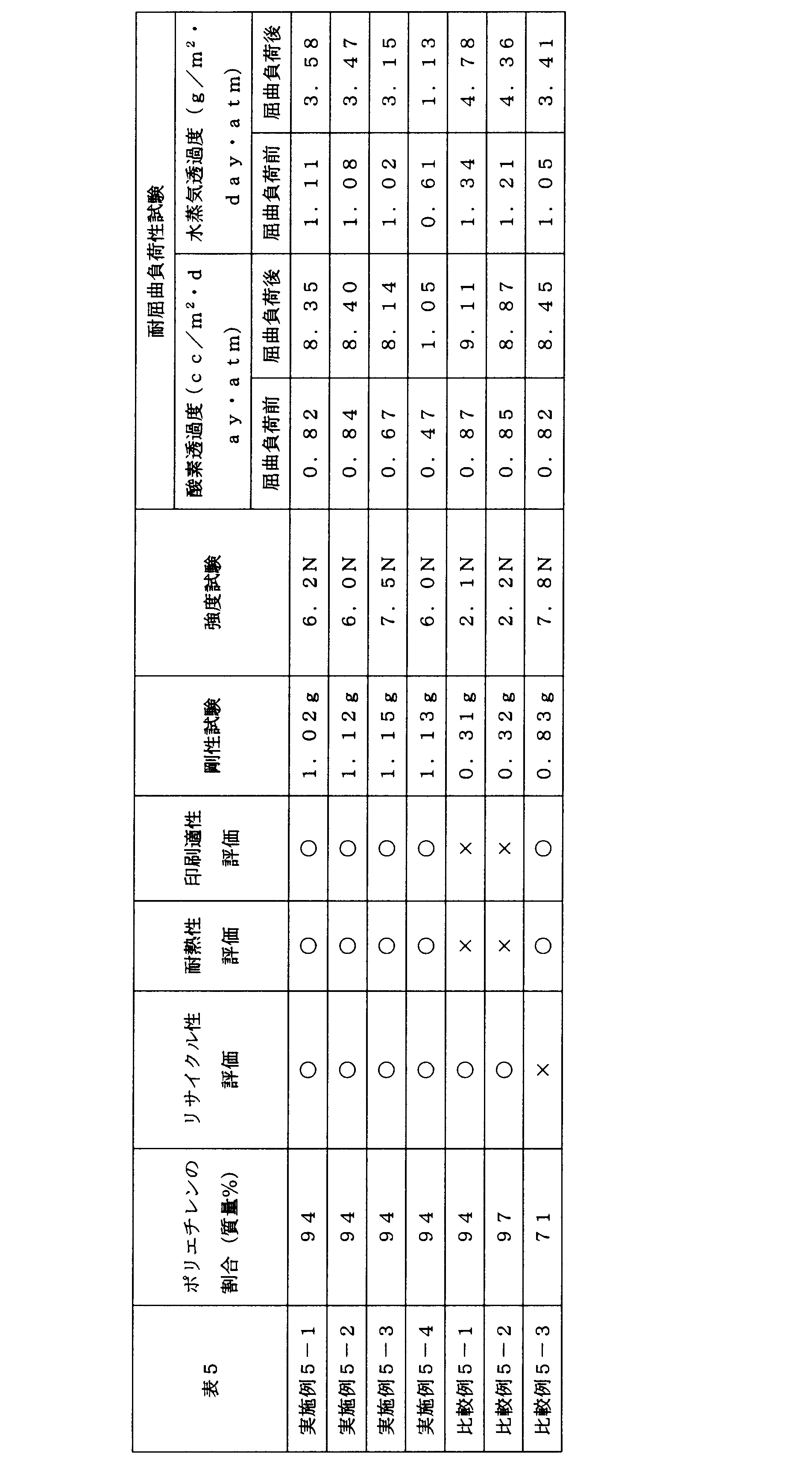
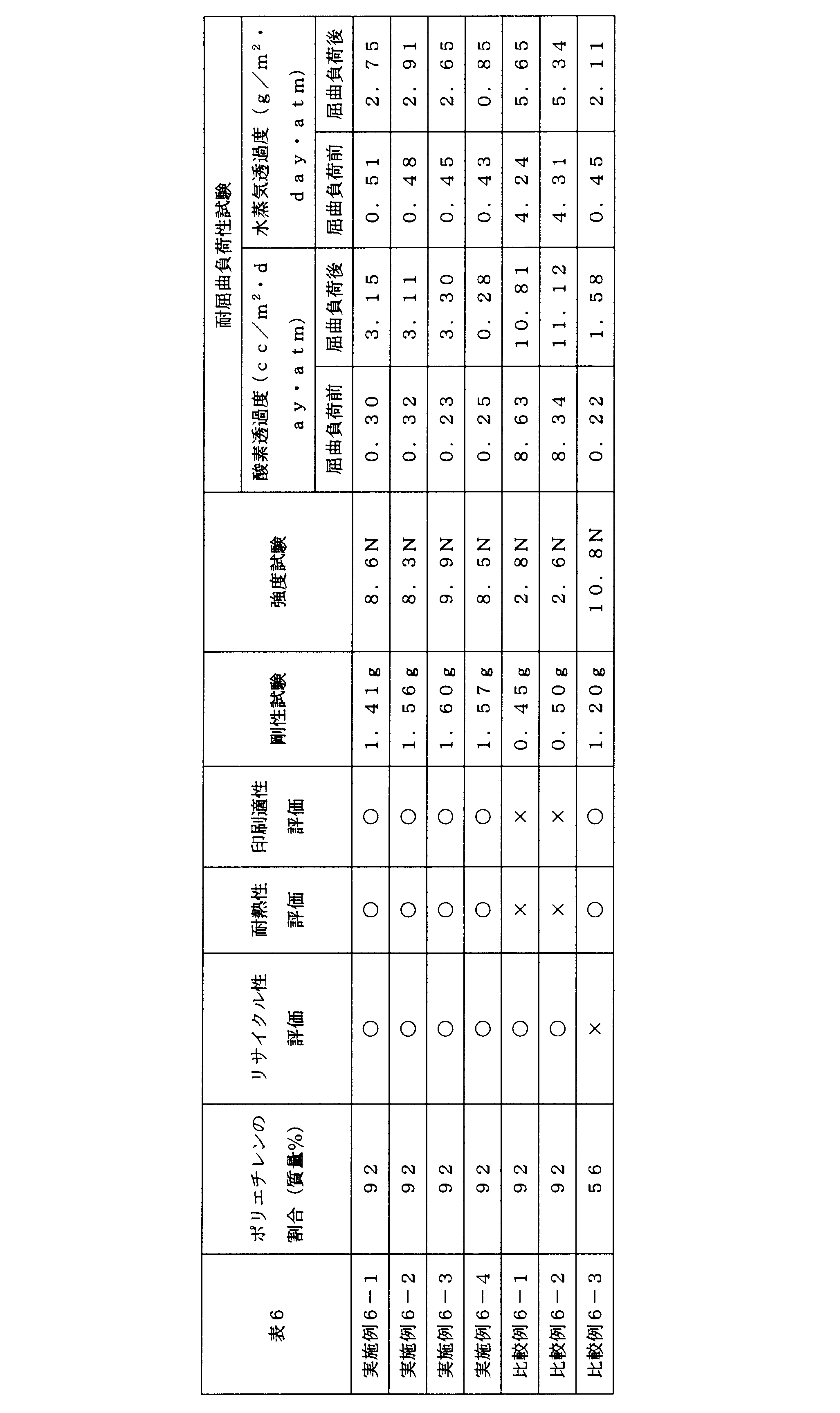
<実施例7-1>
高密度ポリエチレン(密度:0.960g/cm3、融点130℃、MFR:0.85g/10分、Dowchemical社製、商品名:Elite5960)と、
中密度ポリエチレン(密度:0.940g/cm3、融点126℃、MFR:0.85g/10分、Dowchemical社製、商品名:Elite5940)と、
超低密度ポリエチレン(密度:0.870g/cm3、融点55℃、MFR:1.0g/10分、Dowchemical社製、商品名:Affinity EG8100G)と、
をインフレーション成形法により、外側から、高密度ポリエチレン層(12.5μm)、中密度ポリエチレン層(43.75μm)および超低密度ポリエチレン層(6.25μm)を備えるチューブ状のフィルムとして押し出した後、内側の超低密度ポリエチレン層同士を、ゴムロールにより、圧着し、高密度ポリエチレン層(12.5μm)と、中密度ポリエチレン層(43.75μm)と、超低密度ポリエチレン層(12.5μm)と、中密度ポリエチレン層(43.75μm)と、高密度ポリエチレン層(12.5μm)とを備える、厚さ125μmのポリエチレンフィルムを得た。
このポリエチレンフィルムを長手方向(MD)に、5倍の延伸倍率で延伸し、厚さ25μmの多層基材Aを得た。
多層基材Aのヘイズ値を、JIS K 7105に準拠して測定したところ、ヘイズ値は6.2%であった。
多層基材Aの一方の面に、油性グラビアインキ(DICグラフィックス(株)製、商品名:フィナート)を用いて、グラビア印刷法により、画像を形成した。
直鎖状低密度ポリエチレンA(密度:0.923g/cm3、融点121℃、MFR:1.5g/10分、プライムポリマー社製、商品名:SP2510)と、
直鎖状低密度ポリエチレンAおよびバイオマス由来のポリエチレン(密度:0.916g/cm3、MFR:1.3g/10分、バイオマス度:87%、ブラスケム社製、商品名:SLL118)の混合物(2:8(質量基準))と、
直鎖状低密度ポリエチレンB(密度:0.913g/cm3、融点116℃、MFR:2.0g/10分、プライムポリマー社製、商品名:SP1520)と、
をインフレーション成形法により製膜し、厚さ17μmの直鎖状低密度ポリエチレンAからなる層と、厚さ16μmの直鎖状低密度ポリエチレンAおよびバイオマス由来のポリエチレンからなる層と、厚さ17μmの直鎖状低密度ポリエチレンBからなる層を備える、厚さ50μmのヒートシール層Aを作製した。
上記多層基材Aの画像形成面と、上記ヒートシール層Aの直鎖状低密度ポリエチレンAからなる層とを、2液硬化型ウレタン系接着剤(ロックペイント(株)製、商品名:RU-77T/H-7)を介して、積層し、本発明の積層体を得た。
なお、2液硬化型ウレタン系接着剤により形成される接着層の厚さは3.0μmであった。
また、このようにして得られた積層体におけるポリエチレンの割合は、95質量%であった。
なお、2液硬化型ウレタン系接着剤により形成される接着層の厚さは3.0μmであった。
また、このようにして得られた積層体におけるポリエチレンの割合は、95質量%であった。
<実施例7-2>
高密度ポリエチレン(密度:0.960g/cm3、融点130℃、MFR:0.85g/10分、Dowchemical社製、商品名:Elite5960)と、
上記高密度ポリエチレンおよび中密度ポリエチレン(密度:0.940g/cm3、融点126℃、MFR:0.85g/10分、Dowchemical社製、商品名Elite5940)のブレンド樹脂(質量比4:6)と、
上記中密度ポリエチレンと、
超低密度ポリエチレン(密度0.870g/cm3、融点55℃、MFR:1.0g/10分、Dowchemical社製、商品名:Affinity EG8100G)と、
をインフレーション成形法により、外側から、高密度ポリエチレン層(12.5μm)、高密度ポリエチレンおよび中密度ポリエチレンのブレンド樹脂層(12.5μm)、中密度ポリエチレン層(31.25μm)および超低密度ポリエチレン層(6.25μm)を備えるチューブ状のフィルムとして押し出した後、内側の超低密度ポリエチレン層同士を、ゴムロールにより圧着し、高密度ポリエチレン層(12.5μm)と、ブレンド樹脂層(12.5μm)と、中密度ポリエチレン層(31.25μm)と、超低密度ポリエチレン層(12.5μm)と、中密度ポリエチレン層(31.25μm)と、ブレンド樹脂層(12.5μm)とを備える、厚さ125μmのポリエチレンフィルムを得た。
このポリエチレンフィルムを長手方向(MD)に5倍の延伸倍率で延伸し、厚さ25μmの多層基材Bを得た。
多層基材Aを、多層基材Bに変更した以外は、実施例7-1と同様にして積層体を作製した。このようにして得られた積層体におけるポリエチレンの割合は、95質量%であった
<比較例7-1>
上記高密度ポリエチレンと、上記中密度ポリエチレンと、上記超低密度ポリエチレンをインフレーション成形法により、外側から、高密度ポリエチレン層と、中密度ポリエチレン層と、超低密度ポリエチレン層とを備えるチューブ状のフィルムとして押し出した後、内側の超低密度ポリエチレン層同士を、ゴムロールにより、圧着し、高密度ポリエチレン層(2.5μm)と、中密度ポリエチレン層(8.75μm)と、超低密度ポリエチレン層(2.5μm)と、中密度ポリエチレン層(8.75μm)と、高密度ポリエチレン層(2.5μm)と、を備える、厚さ25μmの多層基材aを得た。
多層基材aのヘイズ値を、JIS K 7105に準拠して測定したところ、ヘイズ値は21.3%であった。
多層基材aの一方の面に、上記油性グラビアインキを用いて、グラビア印刷法により、画像を形成した。
上記多層基材aの画像形成面と、上記ヒートシール層Aの直鎖状低密度ポリエチレンAからなる層とを、上記2液硬化型ウレタン系接着剤を介して、積層し、積層体を得た。
なお、2液硬化型ウレタン系接着剤により形成される接着層の厚さは3.0μmであった。
また、このようにして得られた積層体におけるポリエチレンの割合は、95質量%であった。
なお、2液硬化型ウレタン系接着剤により形成される接着層の厚さは3.0μmであった。
また、このようにして得られた積層体におけるポリエチレンの割合は、95質量%であった。
<比較例7-2>
多層基材Aを、厚さ12μmの二軸延伸PETフィルム(東洋紡(株)製、商品名:E5100)に変更した以外は、実施例7-1と同様にして、積層体を作製した。
また、このようにして得られた積層体におけるポリエチレンの割合は、75質量%であった。
多層基材Aを、厚さ12μmの二軸延伸PETフィルム(東洋紡(株)製、商品名:E5100)に変更した以外は、実施例7-1と同様にして、積層体を作製した。
また、このようにして得られた積層体におけるポリエチレンの割合は、75質量%であった。
<実施例8-1>
上記多層基材Aを準備した。
上記多層基材Aを準備した。
多層基材Aの一方の面に、油性グラビアインキ(DICグラフィックス(株)製、商品名:フィナート)を用いて、グラビア印刷法により、画像を形成した。
上記直鎖状低密度ポリエチレンAと、上記直鎖状低密度ポリエチレンAおよび上記バイオマス由来のポリエチレンの混合物(2:8(質量基準))と、上記直鎖状低密度ポリエチレンBと、をインフレーション成形法により製膜し、厚さ34μmの直鎖状低密度ポリエチレンAからなる層と、厚さ32μmの直鎖状低密度ポリエチレンAおよびバイオマス由来のポリエチレンからなる層と、厚さ34μmの直鎖状低密度ポリエチレンBからなる層を備える、厚さ100μmのヒートシール層Bを作製した。
上記多層基材Aの画像形成面と、上記ヒートシール層Bの直鎖状低密度ポリエチレンAからなる層とを、上記2液硬化型ウレタン系接着剤を介して、積層し、本発明の積層体を得た。
なお、2液硬化型ウレタン系接着剤により形成される接着層の厚さは3.0μmであった。
また、このようにして得られた積層体におけるポリエチレンの割合は、97質量%であった。
なお、2液硬化型ウレタン系接着剤により形成される接着層の厚さは3.0μmであった。
また、このようにして得られた積層体におけるポリエチレンの割合は、97質量%であった。
<比較例8-1>
上記多層基材aを準備した。
上記多層基材aを準備した。
多層基材aの一方の面に、上記油性グラビアインキを用いて、グラビア印刷法により、画像を形成した。
上記多層基材aの画像形成面と、上記ヒートシール層Bの直鎖状低密度ポリエチレンAからなる層とを、上記2液硬化型ウレタン系接着剤を介して、積層し、積層体を得た。
なお、2液硬化型ウレタン系接着剤により形成される接着層の厚さは3.0μmであった。
また、このようにして得られた積層体におけるポリエチレンの割合は、97質量%であった。
なお、2液硬化型ウレタン系接着剤により形成される接着層の厚さは3.0μmであった。
また、このようにして得られた積層体におけるポリエチレンの割合は、97質量%であった。
<比較例8-2>
多層基材Aを、厚さ12μmの上記二軸延伸PETフィルムに変更した以外は、実施例8-1と同様にして、積層体を作製した。
また、このようにして得られた積層体におけるポリエチレンの割合は、86質量%であった。
多層基材Aを、厚さ12μmの上記二軸延伸PETフィルムに変更した以外は、実施例8-1と同様にして、積層体を作製した。
また、このようにして得られた積層体におけるポリエチレンの割合は、86質量%であった。
<実施例9-1>
上記基材Aを準備した。
上記基材Aを準備した。
基材Aの一方の面に、油性グラビアインキ(DICグラフィックス(株)製、商品名:フィナート)を用いて、グラビア印刷法により、画像を形成した。
ヒートシール層Aを準備し、この直鎖状低密度ポリエチレンAに、PVD法により厚さ20nmのアルミニウム蒸着膜を形成した。
基材Aの画像形成面と、ヒートシール層Aの蒸着面とを、上記2液硬化型ウレタン系接着剤を介して、積層し、本発明の積層体を得た。
なお、2液硬化型ウレタン系接着剤により形成される接着層の厚さは3.0μmであった。
また、このようにして得られた積層体におけるポリエチレンの割合は、95質量%であった。
なお、2液硬化型ウレタン系接着剤により形成される接着層の厚さは3.0μmであった。
また、このようにして得られた積層体におけるポリエチレンの割合は、95質量%であった。
<実施例9-2>
実施例9-1において、基材Aの画像形成面と、ヒートシール層Aの蒸着面との接着を、イソシアネート化合物およびリン酸変性化合物を含む2液硬化型接着剤(DIC(株)製、PASLIM VM001/VM102CP)により行った以外は、実施例3-1と同様にして、本発明の積層体を作製した。
実施例9-1において、基材Aの画像形成面と、ヒートシール層Aの蒸着面との接着を、イソシアネート化合物およびリン酸変性化合物を含む2液硬化型接着剤(DIC(株)製、PASLIM VM001/VM102CP)により行った以外は、実施例3-1と同様にして、本発明の積層体を作製した。
<比較例9-1>
上記基材aを準備した。
上記基材aを準備した。
基材aの一方の面に、上記油性グラビアインキを用いて、グラビア印刷法により、画像を形成した。
ヒートシール層Aを準備し、この直鎖状低密度ポリエチレンAに、PVD法により厚さ20nmのアルミニウム蒸着膜を形成した。
基材aの画像形成面と、ヒートシール層Aの蒸着面とを、上記2液硬化型ウレタン系接着剤を介して、積層し、積層体を得た。
なお、2液硬化型ウレタン系接着剤により形成される接着層の厚さは3.0μmであった。
また、このようにして得られた積層体におけるポリエチレンの割合は、95質量%であった。
なお、2液硬化型ウレタン系接着剤により形成される接着層の厚さは3.0μmであった。
また、このようにして得られた積層体におけるポリエチレンの割合は、95質量%であった。
<比較例9-2>
基材Aを、厚さ12μmの上記二軸延伸PETフィルムに変更した以外は、実施例3-1と同様にして、積層体を作製した。
また、このようにして得られた積層体におけるポリエチレンの割合は、76質量%であった。
基材Aを、厚さ12μmの上記二軸延伸PETフィルムに変更した以外は、実施例3-1と同様にして、積層体を作製した。
また、このようにして得られた積層体におけるポリエチレンの割合は、76質量%であった。
<実施例10-1>
上記多層基材Aを準備した。
上記多層基材Aを準備した。
多層基材Aの一方の面に、油性グラビアインキ(DICグラフィックス(株)製、商品名:フィナート)を用いて、グラビア印刷法により、画像を形成した。
上記中密度ポリエチレンをインフレーション成形法により製膜し、厚さ100μmのポリエチレンフィルムを得た後、長手方向(MD)に、5倍の延伸倍率で延伸し、厚さ20μmの延伸ポリエチレンフィルムAを得た。次いで、該延伸ポリエチレンフィルムAの一方の面に、PVD法により、厚さ20nmのアルミニウム蒸着膜を形成し、中間層Aを得た。
多層基材Aの画像形成面を、中間層Aの蒸着面に、上記2液硬化型ウレタン系接着剤を介して積層した。2液硬化型ウレタン系接着剤により形成される接着層の厚さは3.0μmであった。
ヒートシール層Aを準備した。次いで、ヒートシール層Aの直鎖状低密度ポリエチレンAからなる層を、中間層Aの非蒸着面に、上記2液硬化型ウレタン系接着剤を介して、積層し、本発明の積層体を得た。
なお、2液硬化型ウレタン系接着剤により形成される接着層の厚さは3.0μmであった。
また、このようにして得られた積層体におけるポリエチレンの割合は、93質量%であった。
なお、2液硬化型ウレタン系接着剤により形成される接着層の厚さは3.0μmであった。
また、このようにして得られた積層体におけるポリエチレンの割合は、93質量%であった。
<実施例10-2>
実施例10-1において、多層基材Aの画像形成面と、中間層Aの蒸着面との接着を、イソシアネート化合物およびリン酸変性化合物を含む2液硬化型接着剤(DIC(株)製、PASLIM VM001/VM102CP)により行った以外は、実施例4-1と同様にして、本発明の積層体を作製した。
実施例10-1において、多層基材Aの画像形成面と、中間層Aの蒸着面との接着を、イソシアネート化合物およびリン酸変性化合物を含む2液硬化型接着剤(DIC(株)製、PASLIM VM001/VM102CP)により行った以外は、実施例4-1と同様にして、本発明の積層体を作製した。
<比較例10-1>
上記多層基材aを準備した。
上記多層基材aを準備した。
多層基材aの一方の面に、油性グラビアインキ(DICグラフィックス(株)製、商品名:フィナート)を用いて、グラビア印刷法により、画像を形成した。
上記中密度ポリエチレンをインフレーション成形法により製膜し、厚さ20μmの延伸ポリエチレンフィルムaを得た。次いで、該延伸ポリエチレンフィルムaの一方の面に、PVD法により、厚さ20nmのアルミニウム蒸着膜を形成し、中間層aを得た。
多層基材aの画像形成面を、中間層aの蒸着面に、上記2液硬化型ウレタン系接着剤を介して積層した。2液硬化型ウレタン系接着剤により形成される接着層の厚さは3.0μmであった。
ヒートシール層Aを準備し、この直鎖状低密度ポリエチレンAからなる層を、中間層aの非蒸着面に、上記2液硬化型ウレタン系接着剤を介して、積層し、積層体を得た。
なお、2液硬化型ウレタン系接着剤により形成される接着層の厚さは3.0μmであった。
また、このようにして得られた積層体におけるポリエチレンの割合は、93質量%であった。
なお、2液硬化型ウレタン系接着剤により形成される接着層の厚さは3.0μmであった。
また、このようにして得られた積層体におけるポリエチレンの割合は、93質量%であった。
<比較例10-2>
多層基材Aおよび中間層Aの延伸ポリエチレンフィルムを、厚さ12μmの二軸延伸ポリエステルフィルム(東洋紡(株)商品名:E5100)に変更した以外は、実施例4-1と同様にして積層体を得た。このようにして得られた積層体におけるポリエチレンの割合は、62質量%であった。
多層基材Aおよび中間層Aの延伸ポリエチレンフィルムを、厚さ12μmの二軸延伸ポリエステルフィルム(東洋紡(株)商品名:E5100)に変更した以外は、実施例4-1と同様にして積層体を得た。このようにして得られた積層体におけるポリエチレンの割合は、62質量%であった。
<リサイクル性評価>
上記実施例および比較例において得られた積層体のリサイクル性を下記評価基準に基づいて、評価した。評価結果を表7~10にまとめた。
(評価基準)
○:積層体におけるポリエチレンの含有量が90質量%以上であった。
×:積層体におけるポリエチレンの含有量が90質量%未満であった。
上記実施例および比較例において得られた積層体のリサイクル性を下記評価基準に基づいて、評価した。評価結果を表7~10にまとめた。
(評価基準)
○:積層体におけるポリエチレンの含有量が90質量%以上であった。
×:積層体におけるポリエチレンの含有量が90質量%未満であった。
<耐熱性評価>
上記実施例7-1および比較例7-1~7-2、実施例9-1~9-2および比較例9-1~9-2並びに実施例10-1~10-2および比較例10-1~10-2において得られた積層体から、縦80mm×横80mmの試験片をそれぞれ2枚ずつ作製した。
2枚の試験片を、ヒートシール層が向かい合うように重ね合わせ、3辺を140℃でヒートシールし、包装袋を作製した。
上記実施例8-1および比較例8-1~8-2において得られた積層体から、縦110mm×横150mmの試験片をそれぞれ2枚ずつ作製した。
2枚の試験片を、ヒートシール層が向かい合うように重ね合わせ、2辺を140℃でヒートシールし、筒状の胴部を形成した。
次いで、上記実施例8-1および比較例8-1~8-2において得られた積層体から、縦110mm×横150mmの試験片を1枚作製し、これをヒートシール層が外側となるように、V字に折り、上記筒状の胴部と140℃でヒートシールし、底部を形成すると共に、スタンドパウチを作製した。
作製した包装材料を目視により観察し、以下の評価基準に基づいて、評価した。評価結果を表7~10にまとめた。
(評価基準)
○:包装材料表面にシワなどが発生しておらず、また、ヒートシールバーへの付着が見られなかった。
×:包装材料表面にシワなどが発生しており、また、ヒートシールバーへの付着が見られ、製袋できなかった。
<印刷適性評価>
上記実施例および比較例において作製した積層体が備える多層基材に形成した画像を目視により観察し、以下の評価基準に基づいて、評価した。評価結果を表1~4にまとめた。
(評価基準)
○:印刷時の寸法安定性が良好であり、擦れ、滲みなどが生じていない良好な画像を形成することができていた。
×:印刷時にフィルムの伸び縮みが発生し、形成した画像に擦れや滲みが生じていた。
上記実施例および比較例において作製した積層体が備える多層基材に形成した画像を目視により観察し、以下の評価基準に基づいて、評価した。評価結果を表1~4にまとめた。
(評価基準)
○:印刷時の寸法安定性が良好であり、擦れ、滲みなどが生じていない良好な画像を形成することができていた。
×:印刷時にフィルムの伸び縮みが発生し、形成した画像に擦れや滲みが生じていた。
<剛性評価>
上記実施例および比較例において作製した積層体を、10mm幅の試験片とし、ループスティフネス測定試験器(東洋精機製作所製、商品名:ループステフネステスタ)によりその剛性を測定した。なお、ループの長さは、60mmとした。測定結果を表7~10にまとめた。
上記実施例および比較例において作製した積層体を、10mm幅の試験片とし、ループスティフネス測定試験器(東洋精機製作所製、商品名:ループステフネステスタ)によりその剛性を測定した。なお、ループの長さは、60mmとした。測定結果を表7~10にまとめた。
<強度試験>
上記実施例および比較例において作製した積層体を、引っ張り試験機(オリエンテック社製、商品名:RTC-1310A)により、直径0.5mmの針を突き刺した際の強度を測定した。なお、突き刺し速度は、50mm/分とした。測定結果を表7~10にまとめた。
上記実施例および比較例において作製した積層体を、引っ張り試験機(オリエンテック社製、商品名:RTC-1310A)により、直径0.5mmの針を突き刺した際の強度を測定した。なお、突き刺し速度は、50mm/分とした。測定結果を表7~10にまとめた。
<耐屈曲負荷性試験>
まず、上記実施例9-1~9-2および比較例9-1~9-2並びに実施例10-1~10-2および比較例10-1~10-2で得られた積層体の酸素透過度および水蒸気透過度を測定した。
酸素透過度の測定には、MOCON製 OXTRAN2/20を使用し、23℃、90%RHn条件下において、水蒸気透過度の測定には、MOCON製 PERMATRAN3/31を使用し、40℃、90%RHの条件下において、それぞれ測定した。
さらに、上記実施例9-1~9-2および比較例9-1~9-2並びに実施例10-1~10-2および比較例10-1~10-2で得られた積層体について、ゲルボフレックステター(テスター産業(株)性、商品名:BE1006BE)を用い、ASTM F 392に準拠して屈曲負荷(ストローク:155mm、屈曲動作:440°)を5回与えた。
屈曲負荷後、積層体の酸素透過度および水蒸気透過度を測定した。
屈曲負荷性試験前後の積層体の酸素透過度および水蒸気透過度を表9および10に示す。
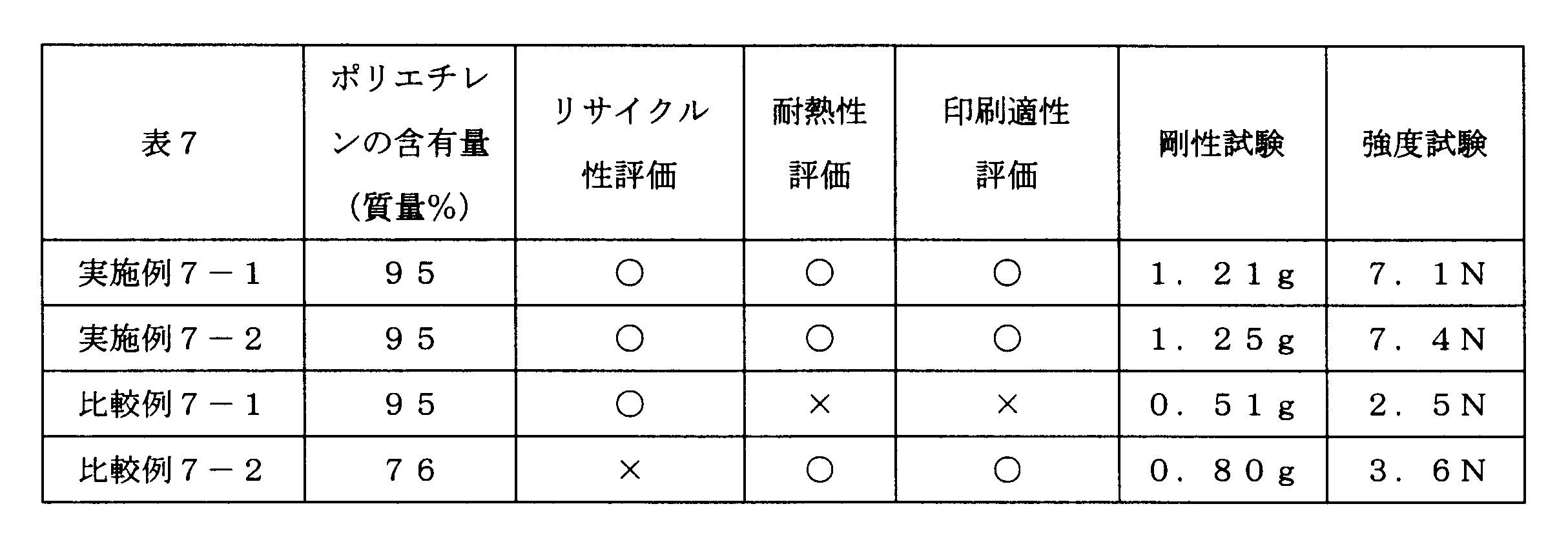
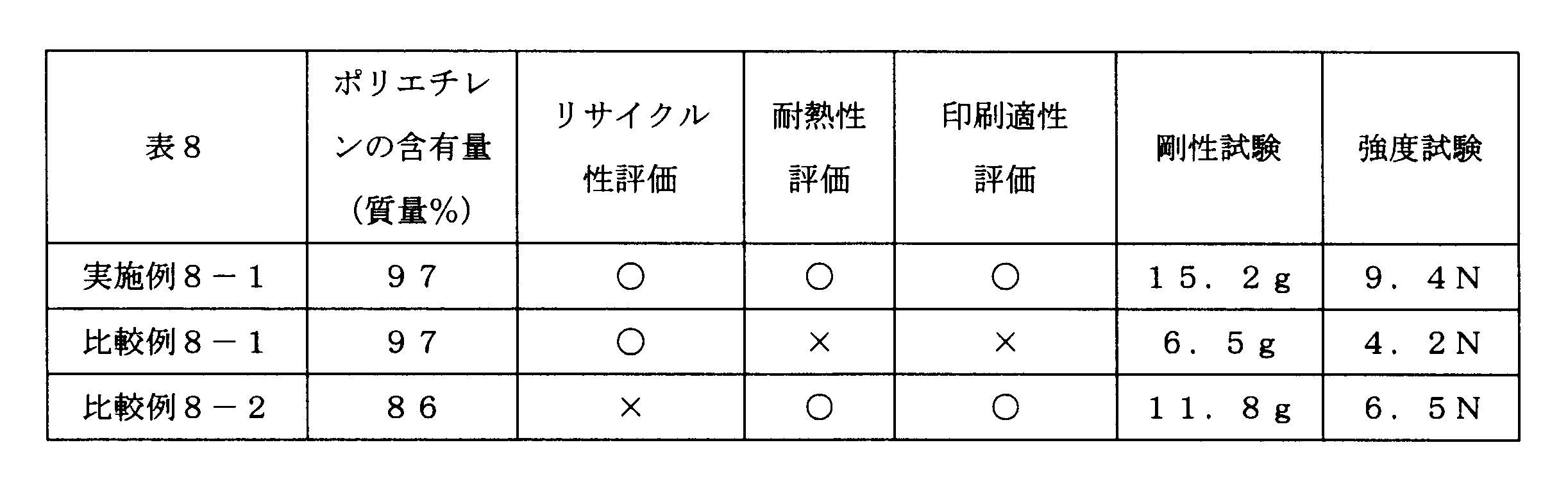
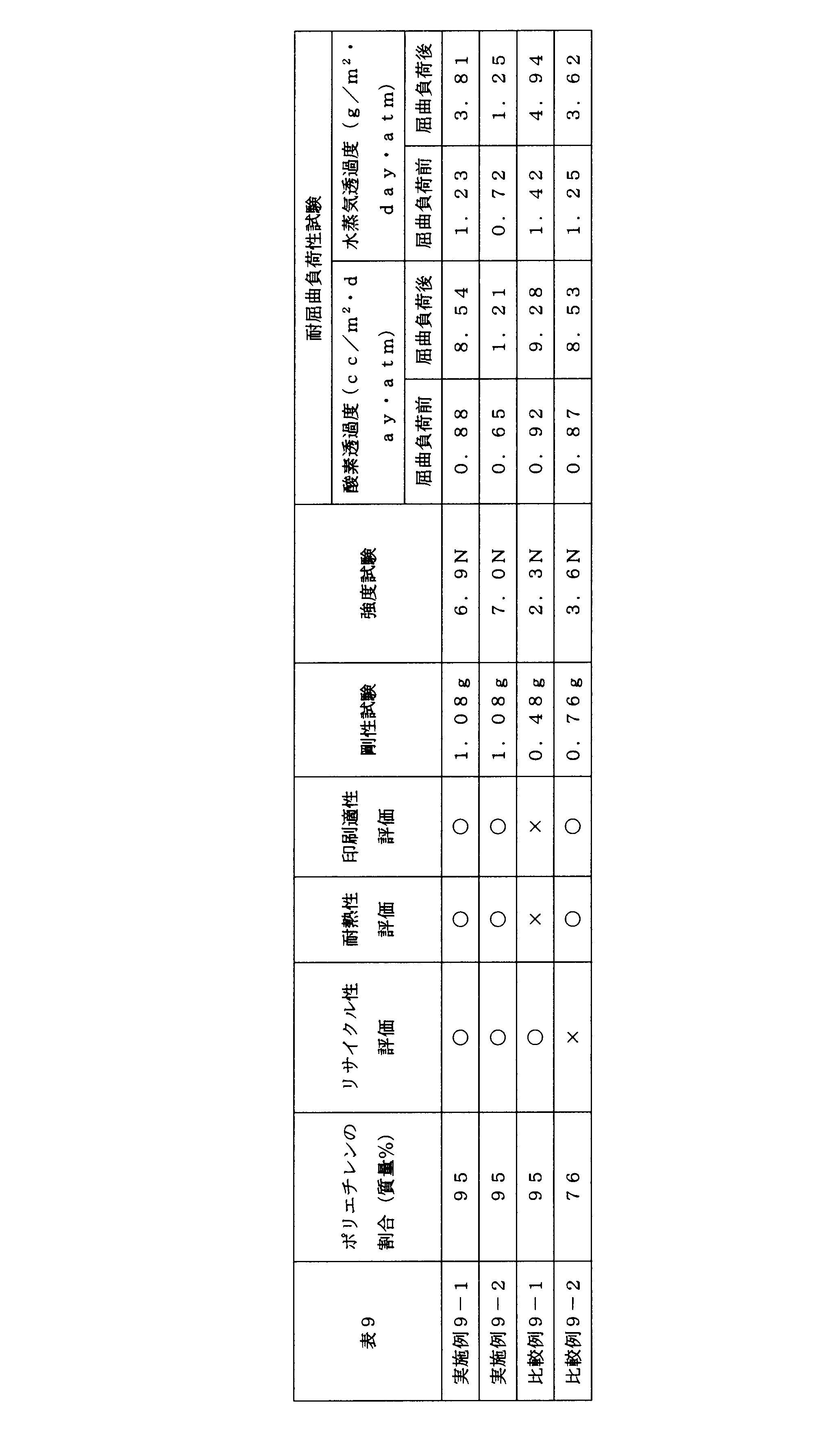
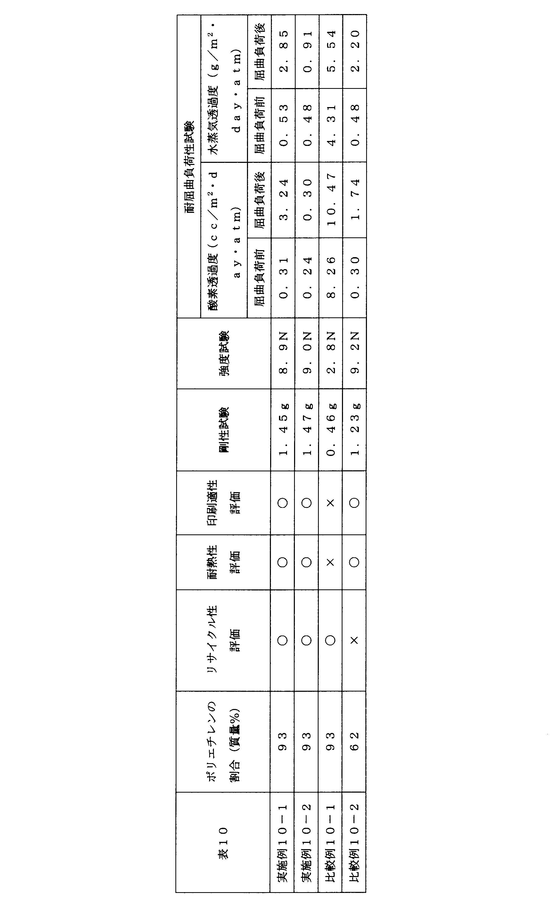
10:積層体、20:基材、30:ヒートシール層、40:中間層、50:接着層、60:高密度ポリエチレン層、70:中密度ポリエチレン層、80:低密度ポリエチレン層、90:中密度ポリエチレン層、100:高密度ポリエチレン層、110:包装袋、120:スタンドパウチ、130:胴部、140:底部
Claims (15)
- 基材と、ヒートシール層とを少なくとも備え、
前記基材および前記ヒートシール層が、同一の材料により構成され、
前記基材は延伸処理が施されており、
前記同一材料がポリエチレンであることを特徴とする、積層体。 - 前記基材が、その少なくとも一方の面に、蒸着膜を備える、請求項1に記載の積層体。
- 前記基材と、前記ヒートシール層との間に接着層を備える、請求項1または2に記載の積層体。
- 前記基材が、アルミニウム蒸着膜を備え、
前記基材と前記ヒートシール層との間に、ポリエステルポリオールとイソシアネート化合物とリン酸変性化合物を含む樹脂組成物の硬化物により構成される接着層を備える、請求項1~3のいずれか一項に記載の積層体。 - 前記基材および前記ヒートシール層の少なくとも一方が、バイオマス由来のポリエチレンを含む、請求項1~4のいずれか一項に記載の積層体。
- 積層体全体におけるポリエチレンの含有量が、90質量%以上である、請求項1~5のいずれか一項に記載の積層体。
- 包装材料用途に用いられる、請求項1~6のいずれか一項に記載の積層体。
- 請求項1~7のいずれか一項に記載の積層体を用いて作製されたものであることを特徴とする、包装材料。
- 包装袋であって、
請求項1~7のいずれか一項に記載の積層体を用いて作製され、
前記ヒートシール層の厚さが、20μm以上60μm以下であることを特徴とする、包装袋。 - スタンドパウチであって、
請求項1~7のいずれか一項に記載の積層体を用いて作製され、
前記ヒートシール層の厚さが、50μm以上200μm以下であることを特徴とするスタンドパウチ。 - 高密度ポリエチレン層と、
中密度ポリエチレン層と、
低密度ポリエチレン層、直鎖状低密度ポリエチレン層または超低密度ポリエチレン層と、
中密度ポリエチレン層と、
高密度ポリエチレン層と、
の五層共押延伸フィルムからなることを特徴とする、多層基材。 - 前記高密度ポリエチレン層の厚さが、1μm以上、20μm以下である、請求項11に記載の多層基材。
- 前記中密度ポリエチレン層の厚さが、1μm以上、30μm以下である、請求項11または12に記載の多層基材。
- 前記低密度ポリエチレン層、前記直鎖状低密度ポリエチレン層または前記超低密度ポリエチレン層の厚さが、1μm以上、10μm以下である、請求項11~13のいずれか一項に記載の多層基材。
- 高密度ポリエチレン層と、
中密度ポリエチレン層と、
高密度ポリエチレンおよび中密度ポリエチレンのブレンド樹脂層と、
低密度ポリエチレン層、直鎖状低密度ポリエチレン層または超低密度ポリエチレン層と、
中密度ポリエチレン層と、
高密度ポリエチレンおよび中密度ポリエチレンのブレンド樹脂層と、
高密度ポリエチレン層と、
の七層共押延伸フィルムからなることを特徴とする、多層基材。
Priority Applications (2)
| Application Number | Priority Date | Filing Date | Title |
|---|---|---|---|
| EP19776629.8A EP3778231A4 (en) | 2018-03-26 | 2019-03-26 | LAMINATE, AND PACKAGING MATERIAL, PACKAGING BAG AND VERTICAL POUCH INCLUDING EACH LAMINATE, AND MULTI-LAYER SUBSTRATE |
| US17/041,982 US20210023828A1 (en) | 2018-03-26 | 2019-03-26 | Laminate, and packaging material, packaging bag and stand-up pouch each comprising said laminate, and multi-layer substrate |
Applications Claiming Priority (16)
| Application Number | Priority Date | Filing Date | Title |
|---|---|---|---|
| JP2018-058416 | 2018-03-26 | ||
| JP2018058403 | 2018-03-26 | ||
| JP2018-058422 | 2018-03-26 | ||
| JP2018-058411 | 2018-03-26 | ||
| JP2018058416 | 2018-03-26 | ||
| JP2018058411A JP2019166810A (ja) | 2018-03-26 | 2018-03-26 | 包装材料用ポリエチレン積層体及び該積層体からなる包装材料 |
| JP2018-058403 | 2018-03-26 | ||
| JP2018058422 | 2018-03-26 | ||
| JP2018087200A JP7192239B2 (ja) | 2018-04-27 | 2018-04-27 | 包装材料用ポリエチレン積層体及び該積層体からなる包装材料 |
| JP2018087181A JP7192238B2 (ja) | 2018-04-27 | 2018-04-27 | 包装材料用ポリエチレン積層体及び該積層体からなる包装材料 |
| JP2018-087181 | 2018-04-27 | ||
| JP2018-087200 | 2018-04-27 | ||
| JP2018-185982 | 2018-09-28 | ||
| JP2018-186164 | 2018-09-28 | ||
| JP2018185982A JP2020055157A (ja) | 2018-09-28 | 2018-09-28 | 積層体、包装材料、包装袋およびスタンドパウチ |
| JP2018186164A JP7151342B2 (ja) | 2018-09-28 | 2018-09-28 | 多層基材、積層体、包装材料、包装袋およびスタンドパウチ |
Publications (1)
| Publication Number | Publication Date |
|---|---|
| WO2019189092A1 true WO2019189092A1 (ja) | 2019-10-03 |
Family
ID=68061757
Family Applications (1)
| Application Number | Title | Priority Date | Filing Date |
|---|---|---|---|
| PCT/JP2019/012708 Ceased WO2019189092A1 (ja) | 2018-03-26 | 2019-03-26 | 積層体、該積層体からなる包装材料、包装袋およびスタンドパウチ、並びに多層基材 |
Country Status (3)
| Country | Link |
|---|---|
| US (1) | US20210023828A1 (ja) |
| EP (1) | EP3778231A4 (ja) |
| WO (1) | WO2019189092A1 (ja) |
Cited By (48)
| Publication number | Priority date | Publication date | Assignee | Title |
|---|---|---|---|---|
| WO2021152969A1 (ja) * | 2020-01-31 | 2021-08-05 | 東洋製罐株式会社 | 積層体、包装袋及びその製造方法 |
| JP2021123042A (ja) * | 2020-02-06 | 2021-08-30 | 凸版印刷株式会社 | 積層体およびそれを用いたスタンディングパウチ |
| JP2021142688A (ja) * | 2020-03-11 | 2021-09-24 | 大日本印刷株式会社 | 包装材料用積層体及び包装材料 |
| WO2021200816A1 (ja) * | 2020-03-31 | 2021-10-07 | 大日本印刷株式会社 | 積層体及び積層体からなる包装容器 |
| JP2021160269A (ja) * | 2020-03-31 | 2021-10-11 | 大日本印刷株式会社 | 積層体および包装容器 |
| JP2021160270A (ja) * | 2020-03-31 | 2021-10-11 | 大日本印刷株式会社 | 積層体および包装容器 |
| JP2021160188A (ja) * | 2020-03-31 | 2021-10-11 | 大日本印刷株式会社 | 積層体および包装容器 |
| JP2021160267A (ja) * | 2020-03-31 | 2021-10-11 | 大日本印刷株式会社 | 積層体および包装容器 |
| JP2022023460A (ja) * | 2020-07-27 | 2022-02-08 | 藤森工業株式会社 | 包装袋用積層体及び自立袋 |
| JP7031783B1 (ja) | 2021-06-21 | 2022-03-08 | 凸版印刷株式会社 | ガスバリアフィルム、積層体、および包装材料 |
| JP7036265B1 (ja) | 2021-06-21 | 2022-03-15 | 凸版印刷株式会社 | ガスバリアフィルム、積層体、および包装材料 |
| JP7036266B1 (ja) | 2021-06-21 | 2022-03-15 | 凸版印刷株式会社 | ガスバリアフィルム、積層体、および包装材料 |
| WO2022092296A1 (ja) * | 2020-10-30 | 2022-05-05 | 大日本印刷株式会社 | ポリエチレン多層基材、印刷基材、積層体及び包装材料 |
| JP2022073027A (ja) * | 2020-10-30 | 2022-05-17 | 大日本印刷株式会社 | ポリエチレン多層基材、印刷基材、積層体及び包装材料 |
| JP2022073902A (ja) * | 2020-10-30 | 2022-05-17 | 大日本印刷株式会社 | ポリエチレン多層基材、印刷基材、積層体及び包装材料 |
| WO2022131264A1 (ja) * | 2020-12-17 | 2022-06-23 | 凸版印刷株式会社 | 積層体、包装袋及びスタンディングパウチ |
| WO2022168867A1 (ja) * | 2021-02-03 | 2022-08-11 | 大日本印刷株式会社 | シーラントフィルム、積層体及び包装容器 |
| JP2022119211A (ja) * | 2021-02-03 | 2022-08-16 | 大日本印刷株式会社 | シーラントフィルム、積層体及び包装袋 |
| JPWO2022172702A1 (ja) * | 2021-02-09 | 2022-08-18 | ||
| CN115175815A (zh) * | 2020-03-03 | 2022-10-11 | 凸版印刷株式会社 | 阻气层叠体及包装袋 |
| JP2022165191A (ja) * | 2021-04-19 | 2022-10-31 | 大日本印刷株式会社 | 積層体及び包装材料 |
| JP2022552625A (ja) * | 2019-10-15 | 2022-12-19 | ダウ グローバル テクノロジーズ エルエルシー | 機械方向に配向された多層ポリエチレンフィルムおよびそれを含む物品 |
| WO2022270490A1 (ja) * | 2021-06-21 | 2022-12-29 | 凸版印刷株式会社 | ガスバリアフィルム、積層体、および包装材料 |
| JP2023024142A (ja) * | 2021-08-06 | 2023-02-16 | 大日本印刷株式会社 | ポリエチレン多層基材、印刷基材、積層体及び包装材料 |
| JPWO2023033159A1 (ja) * | 2021-09-03 | 2023-03-09 | ||
| JP2023031593A (ja) * | 2021-08-25 | 2023-03-09 | 凸版印刷株式会社 | 積層フィルム、包装袋、及び包装体 |
| JP2023047260A (ja) * | 2021-09-24 | 2023-04-05 | 大日本印刷株式会社 | 積層体及び包装容器 |
| JP2023047261A (ja) * | 2021-09-24 | 2023-04-05 | 大日本印刷株式会社 | 積層体及び包装容器 |
| JP2023047262A (ja) * | 2021-09-24 | 2023-04-05 | 大日本印刷株式会社 | 積層体及び包装容器 |
| JP2023048882A (ja) * | 2021-09-28 | 2023-04-07 | 大日本印刷株式会社 | 積層体、包装材料及び包装容器 |
| JP2023048872A (ja) * | 2021-09-28 | 2023-04-07 | 大日本印刷株式会社 | 積層体、包装材料及び包装容器 |
| JP2023048894A (ja) * | 2021-09-28 | 2023-04-07 | 大日本印刷株式会社 | 積層体、包装材料及び包装容器 |
| JP2023056930A (ja) * | 2021-10-08 | 2023-04-20 | 大日本印刷株式会社 | ポリエチレン多層基材、印刷基材、積層体及び包装材料 |
| JP2023056928A (ja) * | 2021-10-08 | 2023-04-20 | 大日本印刷株式会社 | 積層体及び包装材料 |
| CN116568610A (zh) * | 2020-12-17 | 2023-08-08 | 凸版印刷株式会社 | 层叠体以及包装材料 |
| JP2023111720A (ja) * | 2022-01-31 | 2023-08-10 | 大日本印刷株式会社 | ポリエチレン多層基材、印刷基材、積層体及び包装材料 |
| JP2023111712A (ja) * | 2022-01-31 | 2023-08-10 | 大日本印刷株式会社 | ポリエチレン多層基材、印刷基材、積層体及び包装材料 |
| JP2023111717A (ja) * | 2022-01-31 | 2023-08-10 | 大日本印刷株式会社 | ポリエチレン多層基材、印刷基材、積層体及び包装材料 |
| JP2023536181A (ja) * | 2020-09-03 | 2023-08-23 | ザ プロクター アンド ギャンブル カンパニー | ポリエチレンの積層体を含む容器 |
| WO2023243607A1 (ja) * | 2022-06-16 | 2023-12-21 | Toppanホールディングス株式会社 | 積層体及びその製造方法、並びに、包装袋 |
| US20240083148A1 (en) * | 2019-10-10 | 2024-03-14 | Sabic Global Technologies B.V. | Package comprising a bi-directionally oriented polyethylene film |
| JP7453633B1 (ja) * | 2022-10-06 | 2024-03-21 | Dic株式会社 | 多層フィルム及び包装材 |
| WO2024135510A1 (ja) * | 2022-12-22 | 2024-06-27 | Dic株式会社 | 液体包材用積層体、包装材 |
| EP3878636B1 (fr) | 2020-03-10 | 2024-08-07 | Coveris Flexibles France | Procédé de fabrication d'un sac à soufflets, et sac à soufflets perfectionné |
| EP4238884A4 (en) * | 2020-10-30 | 2024-10-02 | Fujimori Kogyo Co., Ltd. | PACKAGING BAG |
| EP4279272A4 (en) * | 2021-01-14 | 2024-12-04 | Fujimori Kogyo Co., Ltd. | MULTILAYER BODIES AND PACKAGING BAGS |
| EP4279273A4 (en) * | 2021-01-18 | 2024-12-04 | Fujimori Kogyo Co., Ltd. | LAMINATED BODY AND PACKAGING BAG |
| JP2024173697A (ja) * | 2023-06-01 | 2024-12-12 | フタムラ化学株式会社 | 二軸延伸ポリエチレンフィルム及びラミネートフィルム並びに包装体 |
Families Citing this family (10)
| Publication number | Priority date | Publication date | Assignee | Title |
|---|---|---|---|---|
| US20200114633A1 (en) | 2018-10-12 | 2020-04-16 | Berry Global, Inc. | Machine direction-oriented polymeric film, and method of making the machine direction-oriented polymeric film |
| KR102722215B1 (ko) * | 2019-09-20 | 2024-10-28 | 노바 케미컬즈 (인터내셔널) 소시에테 아노님 | 재생 폴리에틸렌을 이용한 스탠드업 파우치 |
| CN114423610B (zh) * | 2019-09-20 | 2024-10-11 | 三井化学东赛璐株式会社 | 包装体 |
| EP4095060A4 (en) | 2020-01-24 | 2024-03-13 | Idemitsu Unitech Co., Ltd. | ZIPPER TAPE, ZIPPER TAPE BAG AND METHOD FOR PRODUCING A ZIPPER TAPE BAG |
| CA3179436A1 (en) | 2020-05-27 | 2021-12-02 | Alexander David Jones | Recyclable laminated polyolefin-based film structures |
| US11987026B2 (en) | 2020-05-27 | 2024-05-21 | Proampac Holdings Inc. | Recyclable laminated polyolefin-based film structures |
| US11718075B2 (en) | 2020-07-24 | 2023-08-08 | Proampac Holdings Inc. | High clarity, recyclable, polyethylene-based packaging films |
| MX2023002856A (es) * | 2020-09-11 | 2023-04-03 | Amcor Flexibles North America Inc | Estructura de pelicula de barrera multicapa termoestable. |
| JP7700551B2 (ja) * | 2021-07-20 | 2025-07-01 | artience株式会社 | 積層体の製造方法 |
| KR20240017193A (ko) * | 2022-07-28 | 2024-02-07 | 에스케이이노베이션 주식회사 | 개봉성이 확보된 폴리에틸렌계 적층 포장재 및 이의 제조방법 |
Citations (13)
| Publication number | Priority date | Publication date | Assignee | Title |
|---|---|---|---|---|
| JPH10278196A (ja) * | 1997-04-09 | 1998-10-20 | Daicel Chem Ind Ltd | 複合フィルムおよびその製造方法 |
| JP2002052669A (ja) * | 2000-08-07 | 2002-02-19 | Japan Polyolefins Co Ltd | 積層体およびこれを用いたパウチ |
| JP2009500199A (ja) * | 2005-07-01 | 2009-01-08 | ボロール | 多層フィルム |
| JP2009202519A (ja) | 2008-02-29 | 2009-09-10 | Toppan Printing Co Ltd | ガスバリア性フィルム、包装材料、包装体 |
| JP2011115984A (ja) * | 2009-12-01 | 2011-06-16 | Dainippon Printing Co Ltd | 酸素吸収性積層フィルムおよび包装容器 |
| JP2011131565A (ja) * | 2009-12-25 | 2011-07-07 | Dainippon Printing Co Ltd | 酸素吸収性積層フィルムおよび包装容器 |
| JP2013136689A (ja) * | 2011-12-28 | 2013-07-11 | Dainippon Printing Co Ltd | 包装材シーラント用ポリエチレン系樹脂フィルム |
| JP2013155343A (ja) * | 2012-01-31 | 2013-08-15 | Dainippon Printing Co Ltd | ポリエチレン系樹脂組成物 |
| JP2013177531A (ja) | 2012-02-29 | 2013-09-09 | Dainippon Printing Co Ltd | シーラントフィルム及びそれを用いた包装材 |
| EP2585298B1 (en) | 2010-06-28 | 2014-07-16 | Dow Brasil Indústria e Comércio de Produtos Químicos Ltda. | Single polymer film structures for use in stand-up-pouches |
| WO2017102704A1 (en) | 2015-12-15 | 2017-06-22 | Borealis Ag | Polyethylene based laminated film structure with barrier properties |
| WO2017174605A1 (en) * | 2016-04-04 | 2017-10-12 | Cryovac, Inc. | Thermoplastic film for vacuum skin packaging, method of packaging and uses thereof |
| JP2018016012A (ja) * | 2016-07-29 | 2018-02-01 | 大日本印刷株式会社 | 酸素バリア性を有する積層体および該積層体からなる包装材料 |
Family Cites Families (5)
| Publication number | Priority date | Publication date | Assignee | Title |
|---|---|---|---|---|
| EP0358445A3 (en) * | 1988-09-07 | 1990-11-14 | Tonen Sekiyukagaku K.K. | Polyethylene composite film and label |
| US20040023052A1 (en) * | 2002-07-31 | 2004-02-05 | Benoit Ambroise | Matte surface film |
| US9126269B2 (en) * | 2010-10-26 | 2015-09-08 | Exxonmobil Chemical Patents Inc. | Multilayer polyolefin blown film |
| JP6496981B2 (ja) * | 2014-03-28 | 2019-04-10 | 凸版印刷株式会社 | シーラントフィルム、並びにそれを用いたフィルム積層体及びスタンディングパウチ |
| FI3463859T4 (fi) * | 2016-06-03 | 2025-07-16 | Borealis Ag | Monikerroksinen rakenne |
-
2019
- 2019-03-26 EP EP19776629.8A patent/EP3778231A4/en active Pending
- 2019-03-26 US US17/041,982 patent/US20210023828A1/en active Pending
- 2019-03-26 WO PCT/JP2019/012708 patent/WO2019189092A1/ja not_active Ceased
Patent Citations (13)
| Publication number | Priority date | Publication date | Assignee | Title |
|---|---|---|---|---|
| JPH10278196A (ja) * | 1997-04-09 | 1998-10-20 | Daicel Chem Ind Ltd | 複合フィルムおよびその製造方法 |
| JP2002052669A (ja) * | 2000-08-07 | 2002-02-19 | Japan Polyolefins Co Ltd | 積層体およびこれを用いたパウチ |
| JP2009500199A (ja) * | 2005-07-01 | 2009-01-08 | ボロール | 多層フィルム |
| JP2009202519A (ja) | 2008-02-29 | 2009-09-10 | Toppan Printing Co Ltd | ガスバリア性フィルム、包装材料、包装体 |
| JP2011115984A (ja) * | 2009-12-01 | 2011-06-16 | Dainippon Printing Co Ltd | 酸素吸収性積層フィルムおよび包装容器 |
| JP2011131565A (ja) * | 2009-12-25 | 2011-07-07 | Dainippon Printing Co Ltd | 酸素吸収性積層フィルムおよび包装容器 |
| EP2585298B1 (en) | 2010-06-28 | 2014-07-16 | Dow Brasil Indústria e Comércio de Produtos Químicos Ltda. | Single polymer film structures for use in stand-up-pouches |
| JP2013136689A (ja) * | 2011-12-28 | 2013-07-11 | Dainippon Printing Co Ltd | 包装材シーラント用ポリエチレン系樹脂フィルム |
| JP2013155343A (ja) * | 2012-01-31 | 2013-08-15 | Dainippon Printing Co Ltd | ポリエチレン系樹脂組成物 |
| JP2013177531A (ja) | 2012-02-29 | 2013-09-09 | Dainippon Printing Co Ltd | シーラントフィルム及びそれを用いた包装材 |
| WO2017102704A1 (en) | 2015-12-15 | 2017-06-22 | Borealis Ag | Polyethylene based laminated film structure with barrier properties |
| WO2017174605A1 (en) * | 2016-04-04 | 2017-10-12 | Cryovac, Inc. | Thermoplastic film for vacuum skin packaging, method of packaging and uses thereof |
| JP2018016012A (ja) * | 2016-07-29 | 2018-02-01 | 大日本印刷株式会社 | 酸素バリア性を有する積層体および該積層体からなる包装材料 |
Non-Patent Citations (1)
| Title |
|---|
| See also references of EP3778231A4 |
Cited By (85)
| Publication number | Priority date | Publication date | Assignee | Title |
|---|---|---|---|---|
| US20240083148A1 (en) * | 2019-10-10 | 2024-03-14 | Sabic Global Technologies B.V. | Package comprising a bi-directionally oriented polyethylene film |
| JP2022552625A (ja) * | 2019-10-15 | 2022-12-19 | ダウ グローバル テクノロジーズ エルエルシー | 機械方向に配向された多層ポリエチレンフィルムおよびそれを含む物品 |
| JP2021120204A (ja) * | 2020-01-31 | 2021-08-19 | 東洋製罐株式会社 | 積層体、包装袋及びその製造方法 |
| US12090735B2 (en) | 2020-01-31 | 2024-09-17 | Toyo Seikan Co., Ltd. | Laminate, packaging bag, and method for manufacturing same |
| WO2021152969A1 (ja) * | 2020-01-31 | 2021-08-05 | 東洋製罐株式会社 | 積層体、包装袋及びその製造方法 |
| CN115023345A (zh) * | 2020-01-31 | 2022-09-06 | 东洋制罐株式会社 | 层叠体、包装袋及其制造方法 |
| JP7516764B2 (ja) | 2020-01-31 | 2024-07-17 | 東洋製罐株式会社 | 積層体、包装袋及びその製造方法 |
| JP2021123042A (ja) * | 2020-02-06 | 2021-08-30 | 凸版印刷株式会社 | 積層体およびそれを用いたスタンディングパウチ |
| JP2024071494A (ja) * | 2020-02-06 | 2024-05-24 | Toppanホールディングス株式会社 | 積層体およびそれを用いたスタンディングパウチ |
| JP7463749B2 (ja) | 2020-02-06 | 2024-04-09 | Toppanホールディングス株式会社 | 積層体およびそれを用いたスタンディングパウチ |
| CN115175815A (zh) * | 2020-03-03 | 2022-10-11 | 凸版印刷株式会社 | 阻气层叠体及包装袋 |
| EP4101639A4 (en) * | 2020-03-03 | 2024-02-28 | Toppan Inc. | GAS BARRIER LAMINATE AND PACKING BAG |
| EP3878636B1 (fr) | 2020-03-10 | 2024-08-07 | Coveris Flexibles France | Procédé de fabrication d'un sac à soufflets, et sac à soufflets perfectionné |
| JP2021142688A (ja) * | 2020-03-11 | 2021-09-24 | 大日本印刷株式会社 | 包装材料用積層体及び包装材料 |
| JP7545651B2 (ja) | 2020-03-31 | 2024-09-05 | 大日本印刷株式会社 | 積層体および包装容器 |
| US20230166894A1 (en) * | 2020-03-31 | 2023-06-01 | Dai Nippon Printing Co., Ltd. | Laminate and packaging container including laminate |
| JP2021160267A (ja) * | 2020-03-31 | 2021-10-11 | 大日本印刷株式会社 | 積層体および包装容器 |
| JP2021160188A (ja) * | 2020-03-31 | 2021-10-11 | 大日本印刷株式会社 | 積層体および包装容器 |
| JP2021160270A (ja) * | 2020-03-31 | 2021-10-11 | 大日本印刷株式会社 | 積層体および包装容器 |
| JP2021160269A (ja) * | 2020-03-31 | 2021-10-11 | 大日本印刷株式会社 | 積層体および包装容器 |
| WO2021200816A1 (ja) * | 2020-03-31 | 2021-10-07 | 大日本印刷株式会社 | 積層体及び積層体からなる包装容器 |
| JP2024155979A (ja) * | 2020-03-31 | 2024-10-31 | 大日本印刷株式会社 | 積層体および包装容器 |
| JP7863299B2 (ja) | 2020-03-31 | 2026-05-21 | 大日本印刷株式会社 | 積層体および包装容器 |
| JP7631670B2 (ja) | 2020-03-31 | 2025-02-19 | 大日本印刷株式会社 | 積層体および包装容器 |
| JP2022023460A (ja) * | 2020-07-27 | 2022-02-08 | 藤森工業株式会社 | 包装袋用積層体及び自立袋 |
| JP7507626B2 (ja) | 2020-07-27 | 2024-06-28 | 藤森工業株式会社 | 包装袋用積層体及び自立袋 |
| JP7659045B2 (ja) | 2020-09-03 | 2025-04-08 | ザ プロクター アンド ギャンブル カンパニー | ポリエチレンの積層体を含む容器 |
| JP2023536180A (ja) * | 2020-09-03 | 2023-08-23 | ザ プロクター アンド ギャンブル カンパニー | ポリエチレンの積層体を含む容器 |
| JP2023536181A (ja) * | 2020-09-03 | 2023-08-23 | ザ プロクター アンド ギャンブル カンパニー | ポリエチレンの積層体を含む容器 |
| WO2022092296A1 (ja) * | 2020-10-30 | 2022-05-05 | 大日本印刷株式会社 | ポリエチレン多層基材、印刷基材、積層体及び包装材料 |
| JP2022073902A (ja) * | 2020-10-30 | 2022-05-17 | 大日本印刷株式会社 | ポリエチレン多層基材、印刷基材、積層体及び包装材料 |
| JP2022073027A (ja) * | 2020-10-30 | 2022-05-17 | 大日本印刷株式会社 | ポリエチレン多層基材、印刷基材、積層体及び包装材料 |
| EP4238884A4 (en) * | 2020-10-30 | 2024-10-02 | Fujimori Kogyo Co., Ltd. | PACKAGING BAG |
| US12479640B2 (en) | 2020-10-30 | 2025-11-25 | Zacros Corporation | Packaging bag |
| CN116568610A (zh) * | 2020-12-17 | 2023-08-08 | 凸版印刷株式会社 | 层叠体以及包装材料 |
| CN116568610B (zh) * | 2020-12-17 | 2026-07-24 | 凸版印刷株式会社 | 层叠体以及包装材料 |
| US20230330976A1 (en) * | 2020-12-17 | 2023-10-19 | Toppan Inc. | Multilayer body and packaging material |
| US12565028B2 (en) * | 2020-12-17 | 2026-03-03 | Toppan Holdings Inc. | Multilayer body and packaging material |
| EP4245534A4 (en) * | 2020-12-17 | 2024-04-17 | Toppan Inc. | LAMINATE, PACKAGING BAGS AND STAND-UP BAGS |
| WO2022131264A1 (ja) * | 2020-12-17 | 2022-06-23 | 凸版印刷株式会社 | 積層体、包装袋及びスタンディングパウチ |
| EP4279272A4 (en) * | 2021-01-14 | 2024-12-04 | Fujimori Kogyo Co., Ltd. | MULTILAYER BODIES AND PACKAGING BAGS |
| EP4279273A4 (en) * | 2021-01-18 | 2024-12-04 | Fujimori Kogyo Co., Ltd. | LAMINATED BODY AND PACKAGING BAG |
| JP2022119211A (ja) * | 2021-02-03 | 2022-08-16 | 大日本印刷株式会社 | シーラントフィルム、積層体及び包装袋 |
| WO2022168867A1 (ja) * | 2021-02-03 | 2022-08-11 | 大日本印刷株式会社 | シーラントフィルム、積層体及び包装容器 |
| JPWO2022172702A1 (ja) * | 2021-02-09 | 2022-08-18 | ||
| JP2022165191A (ja) * | 2021-04-19 | 2022-10-31 | 大日本印刷株式会社 | 積層体及び包装材料 |
| JP7036265B1 (ja) | 2021-06-21 | 2022-03-15 | 凸版印刷株式会社 | ガスバリアフィルム、積層体、および包装材料 |
| JP7036266B1 (ja) | 2021-06-21 | 2022-03-15 | 凸版印刷株式会社 | ガスバリアフィルム、積層体、および包装材料 |
| US12636864B2 (en) | 2021-06-21 | 2026-05-26 | Toppan Inc. | Gas barrier film, laminate, and packaging material |
| WO2022270491A1 (ja) * | 2021-06-21 | 2022-12-29 | 凸版印刷株式会社 | ガスバリアフィルム、積層体、および包装材料 |
| JP7031783B1 (ja) | 2021-06-21 | 2022-03-08 | 凸版印刷株式会社 | ガスバリアフィルム、積層体、および包装材料 |
| WO2022270490A1 (ja) * | 2021-06-21 | 2022-12-29 | 凸版印刷株式会社 | ガスバリアフィルム、積層体、および包装材料 |
| JP2023001744A (ja) * | 2021-06-21 | 2023-01-06 | 凸版印刷株式会社 | ガスバリアフィルム、積層体、および包装材料 |
| JP2023001745A (ja) * | 2021-06-21 | 2023-01-06 | 凸版印刷株式会社 | ガスバリアフィルム、積層体、および包装材料 |
| JP2023001746A (ja) * | 2021-06-21 | 2023-01-06 | 凸版印刷株式会社 | ガスバリアフィルム、積層体、および包装材料 |
| JP2023024142A (ja) * | 2021-08-06 | 2023-02-16 | 大日本印刷株式会社 | ポリエチレン多層基材、印刷基材、積層体及び包装材料 |
| JP7836508B2 (ja) | 2021-08-06 | 2026-03-27 | 大日本印刷株式会社 | ポリエチレン多層基材、印刷基材、積層体及び包装材料 |
| JP7797801B2 (ja) | 2021-08-25 | 2026-01-14 | Toppanホールディングス株式会社 | 積層フィルム、包装袋、及び包装体 |
| JP2026034783A (ja) * | 2021-08-25 | 2026-02-27 | Toppanホールディングス株式会社 | 積層フィルム、包装袋、及び包装体 |
| JP2023031593A (ja) * | 2021-08-25 | 2023-03-09 | 凸版印刷株式会社 | 積層フィルム、包装袋、及び包装体 |
| WO2023033159A1 (ja) * | 2021-09-03 | 2023-03-09 | 凸版印刷株式会社 | 積層体、包装体及び包装物品 |
| JPWO2023033159A1 (ja) * | 2021-09-03 | 2023-03-09 | ||
| JP7815814B2 (ja) | 2021-09-24 | 2026-02-18 | 大日本印刷株式会社 | 積層体及び包装容器 |
| JP2023047260A (ja) * | 2021-09-24 | 2023-04-05 | 大日本印刷株式会社 | 積層体及び包装容器 |
| JP2023047261A (ja) * | 2021-09-24 | 2023-04-05 | 大日本印刷株式会社 | 積層体及び包装容器 |
| JP2023047262A (ja) * | 2021-09-24 | 2023-04-05 | 大日本印刷株式会社 | 積層体及び包装容器 |
| JP7815815B2 (ja) | 2021-09-24 | 2026-02-18 | 大日本印刷株式会社 | 積層体及び包装容器 |
| JP2023048894A (ja) * | 2021-09-28 | 2023-04-07 | 大日本印刷株式会社 | 積層体、包装材料及び包装容器 |
| JP2023048882A (ja) * | 2021-09-28 | 2023-04-07 | 大日本印刷株式会社 | 積層体、包装材料及び包装容器 |
| JP2023048872A (ja) * | 2021-09-28 | 2023-04-07 | 大日本印刷株式会社 | 積層体、包装材料及び包装容器 |
| JP7880038B2 (ja) | 2021-10-08 | 2026-06-25 | 大日本印刷株式会社 | ポリエチレン多層基材、印刷基材、積層体及び包装材料 |
| JP2023056928A (ja) * | 2021-10-08 | 2023-04-20 | 大日本印刷株式会社 | 積層体及び包装材料 |
| JP2023056930A (ja) * | 2021-10-08 | 2023-04-20 | 大日本印刷株式会社 | ポリエチレン多層基材、印刷基材、積層体及び包装材料 |
| JP7842964B2 (ja) | 2021-10-08 | 2026-04-09 | 大日本印刷株式会社 | 積層体及び包装材料 |
| JP2023111720A (ja) * | 2022-01-31 | 2023-08-10 | 大日本印刷株式会社 | ポリエチレン多層基材、印刷基材、積層体及び包装材料 |
| JP2023111712A (ja) * | 2022-01-31 | 2023-08-10 | 大日本印刷株式会社 | ポリエチレン多層基材、印刷基材、積層体及び包装材料 |
| JP2023111717A (ja) * | 2022-01-31 | 2023-08-10 | 大日本印刷株式会社 | ポリエチレン多層基材、印刷基材、積層体及び包装材料 |
| WO2023243607A1 (ja) * | 2022-06-16 | 2023-12-21 | Toppanホールディングス株式会社 | 積層体及びその製造方法、並びに、包装袋 |
| WO2024075352A1 (ja) * | 2022-10-06 | 2024-04-11 | Dic株式会社 | 多層フィルム及び包装材 |
| JP7453633B1 (ja) * | 2022-10-06 | 2024-03-21 | Dic株式会社 | 多層フィルム及び包装材 |
| JPWO2024135510A1 (ja) * | 2022-12-22 | 2024-06-27 | ||
| JP7648018B2 (ja) | 2022-12-22 | 2025-03-18 | Dic株式会社 | 液体包材用積層体、包装材 |
| WO2024135510A1 (ja) * | 2022-12-22 | 2024-06-27 | Dic株式会社 | 液体包材用積層体、包装材 |
| JP7737504B2 (ja) | 2023-06-01 | 2025-09-10 | フタムラ化学株式会社 | 二軸延伸ポリエチレンフィルム及びラミネートフィルム並びに包装体 |
| JP2024173697A (ja) * | 2023-06-01 | 2024-12-12 | フタムラ化学株式会社 | 二軸延伸ポリエチレンフィルム及びラミネートフィルム並びに包装体 |
Also Published As
| Publication number | Publication date |
|---|---|
| EP3778231A1 (en) | 2021-02-17 |
| US20210023828A1 (en) | 2021-01-28 |
| EP3778231A4 (en) | 2021-12-22 |
Similar Documents
| Publication | Publication Date | Title |
|---|---|---|
| JP7510622B2 (ja) | 積層体、包装材料、包装袋およびスタンドパウチ | |
| JP7549788B2 (ja) | 積層体および該積層体からなる包装材料 | |
| JP7848065B2 (ja) | 積層体、包装材料、包装袋およびスタンドパウチ | |
| JP7151342B2 (ja) | 多層基材、積層体、包装材料、包装袋およびスタンドパウチ | |
| US20210023828A1 (en) | Laminate, and packaging material, packaging bag and stand-up pouch each comprising said laminate, and multi-layer substrate | |
| JP7704180B2 (ja) | 積層体、包装材料、包装袋およびスタンドパウチ | |
| JP2019171860A (ja) | 積層体および該積層体からなる包装材料 | |
| JP2024161280A (ja) | 積層体、包装材料、包装袋およびスタンドパウチ | |
| JP7496068B2 (ja) | 積層体、包装材料、包装袋およびスタンドパウチ | |
| JP7236046B2 (ja) | 積層体、包装材料、包装袋およびスタンドパウチ | |
| WO2020067426A1 (ja) | 積層体、包装材料、包装袋およびスタンドパウチ | |
| JP7496069B2 (ja) | 積層体、包装材料、包装袋およびスタンドパウチ | |
| JP2024103688A (ja) | 積層体、包装材料、包装袋およびスタンドパウチ | |
| JP2019171862A (ja) | 積層体および該積層体からなる包装材料 | |
| JP7496070B2 (ja) | 積層体、包装材料、包装袋およびスタンドパウチ |
Legal Events
| Date | Code | Title | Description |
|---|---|---|---|
| 121 | Ep: the epo has been informed by wipo that ep was designated in this application |
Ref document number: 19776629 Country of ref document: EP Kind code of ref document: A1 |
|
| NENP | Non-entry into the national phase |
Ref country code: DE |
|
| ENP | Entry into the national phase |
Ref document number: 2019776629 Country of ref document: EP Effective date: 20201026 |