WO2019189103A1 - 操舵機能付ハブユニット、操舵システムおよび車両 - Google Patents
操舵機能付ハブユニット、操舵システムおよび車両 Download PDFInfo
- Publication number
- WO2019189103A1 WO2019189103A1 PCT/JP2019/012728 JP2019012728W WO2019189103A1 WO 2019189103 A1 WO2019189103 A1 WO 2019189103A1 JP 2019012728 W JP2019012728 W JP 2019012728W WO 2019189103 A1 WO2019189103 A1 WO 2019189103A1
- Authority
- WO
- WIPO (PCT)
- Prior art keywords
- steering
- hub unit
- unit
- wheel
- hub
- Prior art date
- Legal status (The legal status is an assumption and is not a legal conclusion. Google has not performed a legal analysis and makes no representation as to the accuracy of the status listed.)
- Ceased
Links
Images


Classifications
-
- B—PERFORMING OPERATIONS; TRANSPORTING
- B60—VEHICLES IN GENERAL
- B60B—VEHICLE WHEELS; CASTORS; AXLES FOR WHEELS OR CASTORS; INCREASING WHEEL ADHESION
- B60B35/00—Axle units; Parts thereof ; Arrangements for lubrication of axles
- B60B35/003—Steerable axles
-
- B—PERFORMING OPERATIONS; TRANSPORTING
- B62—LAND VEHICLES FOR TRAVELLING OTHERWISE THAN ON RAILS
- B62D—MOTOR VEHICLES; TRAILERS
- B62D6/00—Arrangements for automatically controlling steering depending on driving conditions sensed and responded to, e.g. control circuits
- B62D6/002—Arrangements for automatically controlling steering depending on driving conditions sensed and responded to, e.g. control circuits computing target steering angles for front or rear wheels
-
- B—PERFORMING OPERATIONS; TRANSPORTING
- B60—VEHICLES IN GENERAL
- B60B—VEHICLE WHEELS; CASTORS; AXLES FOR WHEELS OR CASTORS; INCREASING WHEEL ADHESION
- B60B35/00—Axle units; Parts thereof ; Arrangements for lubrication of axles
- B60B35/12—Torque-transmitting axles
- B60B35/18—Arrangement of bearings
-
- B—PERFORMING OPERATIONS; TRANSPORTING
- B62—LAND VEHICLES FOR TRAVELLING OTHERWISE THAN ON RAILS
- B62D—MOTOR VEHICLES; TRAILERS
- B62D5/00—Power-assisted or power-driven steering
- B62D5/04—Power-assisted or power-driven steering electrical, e.g. using an electric servo-motor connected to, or forming part of, the steering gear
- B62D5/0418—Electric motor acting on road wheel carriers
-
- F—MECHANICAL ENGINEERING; LIGHTING; HEATING; WEAPONS; BLASTING
- F16—ENGINEERING ELEMENTS AND UNITS; GENERAL MEASURES FOR PRODUCING AND MAINTAINING EFFECTIVE FUNCTIONING OF MACHINES OR INSTALLATIONS; THERMAL INSULATION IN GENERAL
- F16C—SHAFTS; FLEXIBLE SHAFTS; ELEMENTS OR CRANKSHAFT MECHANISMS; ROTARY BODIES OTHER THAN GEARING ELEMENTS; BEARINGS
- F16C19/00—Bearings with rolling contact, for exclusively rotary movement
- F16C19/22—Bearings with rolling contact, for exclusively rotary movement with bearing rollers essentially of the same size in one or more circular rows, e.g. needle bearings
- F16C19/34—Bearings with rolling contact, for exclusively rotary movement with bearing rollers essentially of the same size in one or more circular rows, e.g. needle bearings for both radial and axial load
- F16C19/36—Bearings with rolling contact, for exclusively rotary movement with bearing rollers essentially of the same size in one or more circular rows, e.g. needle bearings for both radial and axial load with a single row of rollers
- F16C19/364—Bearings with rolling contact, for exclusively rotary movement with bearing rollers essentially of the same size in one or more circular rows, e.g. needle bearings for both radial and axial load with a single row of rollers with tapered rollers, i.e. rollers having essentially the shape of a truncated cone
-
- F—MECHANICAL ENGINEERING; LIGHTING; HEATING; WEAPONS; BLASTING
- F16—ENGINEERING ELEMENTS AND UNITS; GENERAL MEASURES FOR PRODUCING AND MAINTAINING EFFECTIVE FUNCTIONING OF MACHINES OR INSTALLATIONS; THERMAL INSULATION IN GENERAL
- F16C—SHAFTS; FLEXIBLE SHAFTS; ELEMENTS OR CRANKSHAFT MECHANISMS; ROTARY BODIES OTHER THAN GEARING ELEMENTS; BEARINGS
- F16C25/00—Bearings for exclusively rotary movement adjustable for wear or play
- F16C25/06—Ball or roller bearings
-
- B—PERFORMING OPERATIONS; TRANSPORTING
- B60—VEHICLES IN GENERAL
- B60B—VEHICLE WHEELS; CASTORS; AXLES FOR WHEELS OR CASTORS; INCREASING WHEEL ADHESION
- B60B35/00—Axle units; Parts thereof ; Arrangements for lubrication of axles
- B60B35/12—Torque-transmitting axles
- B60B35/14—Torque-transmitting axles composite or split, e.g. half- axles; Couplings between axle parts or sections
-
- B—PERFORMING OPERATIONS; TRANSPORTING
- B60—VEHICLES IN GENERAL
- B60G—VEHICLE SUSPENSION ARRANGEMENTS
- B60G2206/00—Indexing codes related to the manufacturing of suspensions: constructional features, the materials used, procedures or tools
- B60G2206/01—Constructional features of suspension elements, e.g. arms, dampers, springs
- B60G2206/50—Constructional features of wheel supports or knuckles, e.g. steering knuckles, spindle attachments
-
- B—PERFORMING OPERATIONS; TRANSPORTING
- B60—VEHICLES IN GENERAL
- B60G—VEHICLE SUSPENSION ARRANGEMENTS
- B60G2500/00—Indexing codes relating to the regulated action or device
- B60G2500/40—Steering
-
- B—PERFORMING OPERATIONS; TRANSPORTING
- B60—VEHICLES IN GENERAL
- B60G—VEHICLE SUSPENSION ARRANGEMENTS
- B60G2800/00—Indexing codes relating to the type of movement or to the condition of the vehicle and to the end result to be achieved by the control action
- B60G2800/90—System Controller type
- B60G2800/96—ASC - Assisted or power Steering control
- B60G2800/963—Steer-by-wire
-
- B—PERFORMING OPERATIONS; TRANSPORTING
- B62—LAND VEHICLES FOR TRAVELLING OTHERWISE THAN ON RAILS
- B62D—MOTOR VEHICLES; TRAILERS
- B62D7/00—Steering linkage; Stub axles or their mountings
- B62D7/06—Steering linkage; Stub axles or their mountings for individually-pivoted wheels, e.g. on king-pins
-
- B—PERFORMING OPERATIONS; TRANSPORTING
- B62—LAND VEHICLES FOR TRAVELLING OTHERWISE THAN ON RAILS
- B62D—MOTOR VEHICLES; TRAILERS
- B62D7/00—Steering linkage; Stub axles or their mountings
- B62D7/18—Steering knuckles; King pins
-
- F—MECHANICAL ENGINEERING; LIGHTING; HEATING; WEAPONS; BLASTING
- F16—ENGINEERING ELEMENTS AND UNITS; GENERAL MEASURES FOR PRODUCING AND MAINTAINING EFFECTIVE FUNCTIONING OF MACHINES OR INSTALLATIONS; THERMAL INSULATION IN GENERAL
- F16C—SHAFTS; FLEXIBLE SHAFTS; ELEMENTS OR CRANKSHAFT MECHANISMS; ROTARY BODIES OTHER THAN GEARING ELEMENTS; BEARINGS
- F16C19/00—Bearings with rolling contact, for exclusively rotary movement
- F16C19/22—Bearings with rolling contact, for exclusively rotary movement with bearing rollers essentially of the same size in one or more circular rows, e.g. needle bearings
- F16C19/34—Bearings with rolling contact, for exclusively rotary movement with bearing rollers essentially of the same size in one or more circular rows, e.g. needle bearings for both radial and axial load
- F16C19/38—Bearings with rolling contact, for exclusively rotary movement with bearing rollers essentially of the same size in one or more circular rows, e.g. needle bearings for both radial and axial load with two or more rows of rollers
- F16C19/381—Bearings with rolling contact, for exclusively rotary movement with bearing rollers essentially of the same size in one or more circular rows, e.g. needle bearings for both radial and axial load with two or more rows of rollers with at least one row for radial load in combination with at least one row for axial load
-
- F—MECHANICAL ENGINEERING; LIGHTING; HEATING; WEAPONS; BLASTING
- F16—ENGINEERING ELEMENTS AND UNITS; GENERAL MEASURES FOR PRODUCING AND MAINTAINING EFFECTIVE FUNCTIONING OF MACHINES OR INSTALLATIONS; THERMAL INSULATION IN GENERAL
- F16C—SHAFTS; FLEXIBLE SHAFTS; ELEMENTS OR CRANKSHAFT MECHANISMS; ROTARY BODIES OTHER THAN GEARING ELEMENTS; BEARINGS
- F16C23/00—Bearings for exclusively rotary movement adjustable for aligning or positioning
- F16C23/06—Ball or roller bearings
-
- F—MECHANICAL ENGINEERING; LIGHTING; HEATING; WEAPONS; BLASTING
- F16—ENGINEERING ELEMENTS AND UNITS; GENERAL MEASURES FOR PRODUCING AND MAINTAINING EFFECTIVE FUNCTIONING OF MACHINES OR INSTALLATIONS; THERMAL INSULATION IN GENERAL
- F16C—SHAFTS; FLEXIBLE SHAFTS; ELEMENTS OR CRANKSHAFT MECHANISMS; ROTARY BODIES OTHER THAN GEARING ELEMENTS; BEARINGS
- F16C2326/00—Articles relating to transporting
- F16C2326/01—Parts of vehicles in general
- F16C2326/02—Wheel hubs or castors
-
- F—MECHANICAL ENGINEERING; LIGHTING; HEATING; WEAPONS; BLASTING
- F16—ENGINEERING ELEMENTS AND UNITS; GENERAL MEASURES FOR PRODUCING AND MAINTAINING EFFECTIVE FUNCTIONING OF MACHINES OR INSTALLATIONS; THERMAL INSULATION IN GENERAL
- F16C—SHAFTS; FLEXIBLE SHAFTS; ELEMENTS OR CRANKSHAFT MECHANISMS; ROTARY BODIES OTHER THAN GEARING ELEMENTS; BEARINGS
- F16C2326/00—Articles relating to transporting
- F16C2326/20—Land vehicles
- F16C2326/24—Steering systems, e.g. steering rods or columns
Definitions
- the present invention relates to a vehicle equipped with a hub unit with a steering function, a steering system, and a hub unit with a steering function, and relates to a technique for improving fuel efficiency, stabilizing vehicle running performance and improving reliability.
- the vehicle geometry includes (1) “Parallel geometry” where the left and right wheels have the same turning angle, and (2) The turning inner wheel angle is turned larger than the turning outer wheel angle in order to make the turning center one place. Ackermann geometry is known.
- Ackermann geometry is a difference in rudder angle between the left and right wheels so that each wheel turns around a common point in order to smoothly turn the wheels when turning at low speeds where the centrifugal force acting on the vehicle can be ignored. Is set. However, in high-speed turning where the centrifugal force cannot be ignored, it is desirable that the wheels generate a cornering force in a direction that balances with the centrifugal force. Therefore, the parallel geometry is preferable to the Ackermann geometry.
- a general vehicle steering device is mechanically connected to a wheel, generally only a single fixed steering geometry can be taken, and an intermediate between the Ackermann geometry and the parallel geometry. Often set to static geometry. However, in this case, the difference in steering angle between the left and right wheels is insufficient in the low speed range, the steering angle of the outer wheel is excessive, and the steering angle of the inner wheel is excessive in the high speed range. If there is an unnecessary bias in the lateral force distribution of the inner and outer wheels in this way, it will cause fuel consumption deterioration due to worsening of running resistance and premature wear of the wheels, and the smoothness of cornering due to the inefficient use of the inner and outer wheels. There is a problem that is damaged.
- Patent Document 1 A steer-by-wire system (apparatus) represented by Patent Document 1 and the like includes a steering angle sensor for detecting a steering angle of a steering wheel and a torque sensor for detecting a steering reaction force actually applied to the steering shaft. These sensor signals are used to operate the actuator of the steering device, and the left and right wheels are steered by one steering device. In this case, a large motor is incorporated in the steering device disposed in the front portion of the chassis, and the entire system becomes large. The front part of the chassis has many other mechanisms such as engines and transmissions, and space is limited.
- Patent Document 2 The steering system operates a steering actuator that can independently steer each wheel of a front wheel or a rear wheel system, but this steering actuator is fixed to a chassis, and it is difficult to secure a space as in Patent Document 1.
- the wheel angle can be freely controlled independently according to the driving conditions, but the steering actuator is fixed to the chassis, and the length of the tie rod connecting the steering actuator and the wheel is Since it is constant, the wheel angle changes greatly in a situation where the vehicle sinks into the tire, such as during cornering, or in a situation where it rises, and it is difficult to adjust to a predetermined angle.
- Patent Document 3 Since the hub bearing is cantilevered with respect to the steered shaft, the rigidity is lowered, and the steering geometry may be changed by the traveling G. Further, when a reduction gear is provided on the steered shaft, the size of the entire mechanism including the motor increases. When the size of the entire mechanism is increased, it is difficult to arrange the entire mechanism on the inner periphery of the wheel. Moreover, when a reduction gear with a large reduction ratio is provided, the responsiveness decreases.
- the conventional mechanism having a steering function for each wheel can reduce the space required for the steering device in the front portion of the chassis, but is intended to change the toe angle or the camber angle of the wheel in the vehicle. For this reason, a plurality of motors and speed reduction mechanisms are required, resulting in a complicated configuration. Moreover, it is difficult to ensure rigidity, and it is necessary to increase the size and weight in order to ensure rigidity. Further, when the kingpin axis and the steered axis coincide with each other, since the component parts are arranged behind the hub unit (vehicle body side), the overall size increases and becomes heavy.
- Patent Document 4 These actuators must always receive a load from the wheel during traveling.
- the load reversely input from the wheel side is received by this gear portion.
- the wheel may receive a sudden impact load, and an abnormality may occur in the gear receiving the load.
- JP 2005-349845 A Japanese Patent No. 4230947 German Patent Application Publication No. 10201206337 Japanese Patent No. 5615094
- All-wheel drive (abbreviation: AWD), FF, and FR vehicles usually have an engine and transmission at the front, and the interior space of the front chassis is a space, and miniaturization is required for each part. It has been. Since the steering device for steering the front wheels is also arranged in the same place, it is difficult to employ a complicated and large mechanism. In addition, when the steering device and the wheels are mechanically connected from the steering wheel, the vibration received by the tire when traveling on a rough road such as a gravel road or a stone pavement is transmitted as vibration uncomfortable for the driver.
- An object of the present invention is to provide a hub unit with a steering function, a steering system, and a vehicle equipped with a hub unit with a steering function, which has a simple structure, is highly rigid, and can be downsized.
- the hub unit with a steering function is a hub unit with a steering function that is used in a steer-by-wire system in which a steering input unit and a wheel are mechanically separated and steer the wheel, and a hub bearing that supports the wheel is provided.
- the steering actuator that is driven to rotate about an axis, and the hub unit main body is supported by the unit support member via a rolling bearing to which a preload is applied.
- the preload is set, for example, so that the initial preload does not come off even when the weight of the vehicle acts on the hub unit.
- the hub unit body including the hub bearing that supports the wheel can be freely rotated around the turning shaft center by driving the steering actuator. For this reason, steering can be performed independently for each wheel, and the toe angle of the wheel can be arbitrarily changed according to the traveling state of the vehicle. Since the hub unit main body is supported by the unit support member via the pre-loaded rolling bearing, the hub unit with a steering function can ensure rigidity as a steering device.
- this configuration When this configuration is applied to the front wheels, the front wheel is steered by the driver's steering operation. Steering can be performed independently for each wheel. In a vehicle with front wheel steering, this configuration can be applied to the rear wheels. In this case, the steering function of the rear wheels can reduce the turning radius of the vehicle and improve the turning performance. Since it is not necessary to ensure a large steering angle of the rear wheels, the steering actuator can be reduced in size. In either case, since the hub unit body can be freely rotated around the turning axis by the steering actuator, for example, the toe angle of the wheel can be freely left and right independent depending on the traveling state of the vehicle. Can be changed. Since the steering mechanism is provided in the hub unit, there is room in the space of the chassis front part.
- the steering angle of the left and right steering wheels can be reduced, and the turning performance can be improved. Furthermore, during straight running, it is possible to make adjustments such as ensuring running stability without reducing fuel consumption by adjusting the toe angle in accordance with each scene.
- the steering input unit such as the steering wheel and the wheel are not mechanically connected, vibration uncomfortable for the driver can be blocked when traveling on a gravel road or a cobblestone. It is also possible to transmit only information necessary for the driver to the driver from, for example, a reaction force actuator of the steering input unit.
- the steering system according to the present invention is a steering system including a hub unit with a steering function having the above-described configuration according to the present invention and a control device that controls a rolling actuator of the hub unit with a steering function.
- a control unit that outputs a current command signal according to a given steering angle command signal, and an actuator drive control that drives and controls the rolling actuator by outputting a drive current according to the current command signal input from the control unit Part.
- control unit outputs a current command signal corresponding to the given steering angle command signal.
- the actuator drive control unit outputs a current corresponding to the current command signal input from the control unit, and drives and controls the rolling actuator. Therefore, it is possible to arbitrarily change the steering angle of the wheel in addition to steering by the driver's operation of the steering input unit.
- the vehicle according to the first aspect of the present invention is such that the left and right front wheels are equipped with the steering function-equipped hub unit of the above-described configuration of the present invention.
- a vehicle according to a second aspect of the present invention is such that the right and left rear wheels are equipped with the steering function-equipped hub unit of the above-described configuration of the present invention.
- a vehicle according to a third aspect of the present invention is such that the hub unit with a steering function having the above-described configuration according to the present invention is mounted on the left and right front wheels and the left and right rear wheels.
- the front wheels are generally steered wheels, but when the hub unit with a steering function of the present invention is applied to the steered wheels, it is effective for adjusting the toe angle during traveling.
- the rear wheels are generally non-steered wheels, when applied to non-steered wheels, the minimum turning radius during low-speed traveling can be reduced by slightly steering the non-steered wheels.
- this hub unit with a steering function is applied to the front and rear wheels, it is effective for adjusting the toe angle during traveling, and the minimum turning radius during low-speed traveling can be reduced.
- FIG. 10 is a schematic plan view of still another example of a vehicle including the steering function-equipped hub unit.
- a hub unit with a steering function according to a first embodiment of the present invention will be described with reference to FIGS.
- This hub unit with a steering function is applied to a steer-by-wire system in which a steering input unit which is a handle and a wheel are mechanically separated and the wheel is steered.
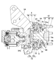
- the steering function-equipped hub unit 1 includes a hub unit body 2, a unit support member 3, a rolling bearing 4 that is a rotation-allowing support component, and a steering actuator 5.
- the unit support member 3 is provided integrally with a knuckle 6 that is a suspension frame part.
- the knuckle 6 in this example is fixed so as not to rotate in the steering direction, and is attached to a normal suspension device 12. Therefore, the steering of the wheel 9 of the vehicle equipped with the hub unit 1 with a steering function is determined only by the operation of the steering actuator 5.
- the hub unit 1 with a steering function is used to independently change the angles of the left and right wheels 9 in addition to the steering of the wheels 9 by a steering operation.
- the actuator body 7 of the steering actuator 5 is provided on the inboard side of the unit support member 3, and the hub unit body 2 is provided on the outboard side of the unit support member 3.
- the vehicle width direction outer side of the vehicle is referred to as an outboard side
- the vehicle width direction center side of the vehicle is referred to as an inboard side.
- the hub unit main body 2 and the actuator main body 7 are connected by a joint portion 8.
- the joint portion 8 is provided with a boot (not shown) for waterproofing and dustproofing.
- the joint portion 8 is provided with a reaction force sensor Sa described later.
- the hub unit main body 2 is supported by the unit support member 3 via rolling bearings 4 and 4 at two upper and lower positions so as to be rotatable around the turning axis A extending in the vertical direction. Yes.
- the turning axis A is an axis different from the rotation axis O of the wheel 9.
- the wheel 9 includes a wheel 9a and a tire 9b.
- the hub unit 1 with a steering function is provided on the knuckle 6 of the suspension device 12 (FIG. 1) and is provided on the left and right front wheels 9F and 9F which are steering wheels in the vehicle 10, respectively.
- the suspension device 12 (FIG. 1) uses, for example, a strut suspension mechanism that directly fixes the shock absorber to the knuckle 6. However, a multi-link suspension mechanism or other suspension mechanisms may be applied.
- the hub unit 1 with a steering function and the steering input portion 11a that is a steering wheel are not mechanically coupled but are electrically connected only by an electrical signal.
- the steering input unit 11a is provided with a sensor Sb that detects and outputs a rotation angle and an angular velocity by a driver's steering operation.
- the steer-by-wire system operates the steering actuators 5 and 5 based on the electric signal output from the sensor Sb, and freely steers the left and right front wheels 9F and 9F independently according to the traveling conditions of the vehicle 10. .
- a rotation angle detecting means such as a resolver for detecting the rotation angle can be adopted.
- the angular velocity is obtained by differentiating the rotation angle detected by the rotation angle detection means.
- the steer-by-wire system includes a reaction force sensor Sa that detects a reaction force from a tire, and a reaction force that is applied to the steering input unit 11a only from the reaction force detected by the reaction force sensor Sa to information necessary for the driver (steering reaction force). And an actuator Ha.
- the reaction force sensor Sa is a sensor for detecting a reaction force acting on the joint portion 8, and for example, a load cell or a load sensor is applied.
- the reaction force sensor Sa detects the axial force applied to the linear motion output unit 25a by converting the linear motion output unit 25a of the steering actuator 5 back and forth, and converts it into an electrical signal.
- the relationship between the electrical signal obtained by the reaction force sensor Sa and the steering reaction force generated by the reaction force actuator Ha is determined by, for example, a map or an arithmetic expression. Therefore, according to this steer-by-wire system, it is possible to realize a steering feeling according to the vehicle situation.
- the steering actuators 5 and 5 may be operated according to commands from an unillustrated automatic driving device or driving support device.
- the hub unit main body 2 includes a hub bearing 15 for supporting the wheels 9, an outer ring 16, and an arm portion 17 (FIG. 3) that is a steering force receiving portion described later.
- the hub bearing 15 includes an inner ring 18, an outer ring 19, and rolling elements 20 such as balls interposed between the inner and outer rings 18 and 19, and serves to connect the vehicle body side member and the wheel 9.
- the hub bearing 15 is an angular ball bearing in which the outer ring 19 is a fixed ring, the inner ring 18 is a rotating ring, and the rolling elements 20 are in a double row.
- the inner ring 18 includes a hub ring portion 18a having a hub flange 18aa and constituting a race surface on the outboard side, and an inner ring portion 18b constituting a race surface on the inboard side.
- the wheel 9a of the wheel 9 is bolted to the hub flange 18aa so as to overlap the brake rotor 21a.
- the inner ring 18 rotates around the rotation axis O.
- the outer ring 16 has an annular portion 16a fitted to the outer peripheral surface of the outer ring 19, and trunnion shaft-like mounting shaft portions 16b and 16b provided so as to protrude vertically from the outer periphery of the annular portion 16a.
- Each attachment shaft portion 16 b is provided coaxially with the turning shaft center A.
- the brake 21 has a brake rotor 21a and a brake caliper 21b.
- the brake caliper 21b is mounted on two upper and lower brake caliper mounting portions 22 (FIG. 5) formed integrally with the outer ring 19 so as to project into an arm shape.
- a tapered roller bearing is applied as the rolling bearing 4 that is each rotation-supporting support component.
- a tapered roller bearing is applied as the rolling bearing (rotation permitting support component) 4.
- the rolling bearing 4 includes an inner ring 4a fitted to the outer periphery of the mounting shaft portion 16b, an outer ring 4b fitted to the unit support member 3, and a plurality of rolling elements 4c interposed between the inner and outer rings 4a and 4b. .
- the unit support member 3 includes a unit support member main body 3A and a unit support member combined body 3B.
- a substantially ring-shaped unit support member assembly 3B is detachably fixed to the end of the unit support member main body 3A on the outboard side.
- Partial concave spherical fitting hole forming portions 3a are respectively formed on the upper and lower portions of the side surface of the inboard side of the unit support member assembly 3B.
- partial concave spherical fitting hole forming portions 3Aa are respectively formed on the upper and lower portions of the outboard side end of the unit support member main body 3A.
- the unit support member combination 3B is fixed to the outboard side end of the unit support member main body 3A.
- the fitting hole forming portions 3a and 3Aa are combined with each other to form a fitting hole that is connected to the entire circumference.
- the outer ring 4b is fitted in the fitting hole.
- the unit support member 3 is indicated by a one-dot chain line.
- each mounting shaft portion 16b of the outer ring 16 is formed with a female screw portion extending in the radial direction, and is provided with a bolt 23 that is screwed into the female screw portion.
- a disc-shaped pressing member 24 is interposed on the end surface of the inner ring 4a, and a preload is applied to each rolling bearing 4 by applying a pressing force to the end surface of the inner ring 4a by a bolt 23 screwed into the female screw portion. Yes.
- the rigidity of each rolling bearing 4 can be improved. Even when the weight of the vehicle acts on the hub unit, the initial preload is set so as not to be released. For this reason, this hub unit with a steering function can ensure the rigidity as a steering device.
- the rolling bearing 4 is not limited to a tapered roller bearing, and an angular ball bearing can be used depending on the use conditions such as the maximum load. Even in that case, a preload can be applied in the same manner as described above.
- the arm portion 17 is a portion serving as an action point for applying a steering force to the outer ring 19 of the hub bearing 15, and projects integrally with a part of the outer periphery of the outer ring 19.
- the arm portion 17 is rotatably connected to the linear motion output portion 25 a of the steering actuator 5 via the joint portion 8.
- the hub unit main body 2 rotates around the turning axis A (FIG. 1), that is, is steered.
- FIGS. 8 and 9 show the state of the right wheel 9 when turning left and when turning right, respectively.
- the steering angle of the wheel 9 is changed by moving a linear motion mechanism 25 of the steering actuator 5 described later by a motor 26.
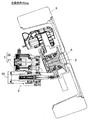
- the steering actuator 5 includes an actuator body 7 that rotates the hub unit body 2 about the turning axis A (FIG. 1). As shown in FIG. 2, the actuator body 7 converts a motor 26, a speed reducer 27 that decelerates the rotation of the motor 26, and a forward / reverse rotation output of the speed reducer 27 into a reciprocating linear motion of the linear motion output unit 25a. And a linear motion mechanism 25.
- the motor 26 is, for example, a permanent magnet type synchronous motor, but may be a DC motor or an induction motor.
- the reducer 27 may be omitted.
- the reduction gear 27 can use a wrapping transmission mechanism such as a belt transmission mechanism or a gear train, and a belt transmission mechanism is used in the example of FIG.
- the reducer 27 includes a drive pulley 27a, a driven pulley 27b, and a belt 27c.
- a drive pulley 27 a is coupled to the motor shaft of the motor 26, and a driven pulley 27 b is provided in the linear motion mechanism 25.
- the driven pulley 27b is disposed in parallel to the motor shaft.
- the driving force of the motor 26 is transmitted from the drive pulley 27a to the driven pulley 27b via the belt 27c.
- the drive pulley 27a, the driven pulley 27b, and the belt 27c constitute a winding-type speed reducer 27.
- a feed screw mechanism such as a slide screw or a ball screw, a rack and pinion mechanism, or the like can be used.
- a feed screw mechanism using a trapezoidal screw slide screw is used. Since the linear motion mechanism 25 includes a feed screw mechanism that uses a sliding screw of the trapezoidal screw, the effect of preventing reverse input from the tire 9b can be enhanced.
- the actuator body 7 including the motor 26, the speed reducer 27, and the linear motion mechanism 25 is assembled as a semi-assembly and is detachably attached to the case 6b with bolts or the like. A mechanism that directly transmits the driving force of the motor 26 to the linear motion mechanism 25 without using a reduction gear is also possible.
- the case 6b is integrally formed with the unit support member main body 3A as a part of the unit support member 3.
- the case 6 b is formed in a bottomed cylindrical shape, and is provided with a motor housing portion that supports the motor 26 and a linear motion mechanism housing portion that supports the linear motion mechanism 25.
- a fitting hole for supporting the motor 26 at a predetermined position in the case is formed in the motor housing portion.
- the linear motion mechanism accommodating portion is formed with a fitting hole for supporting the linear motion mechanism 25 at a predetermined position in the case, a through hole for allowing the linear motion output portion 25a to advance and retreat.
- the unit support member main body 3A includes the case 6b and a shock absorber mounting portion 6c that is a mounting portion of the shock absorber.
- the shock absorber mounting portion 6c is also formed integrally with the unit support member main body 3A.
- a shock absorber mounting portion 6c is formed on the upper portion of the outer surface portion of the unit support member main body 3A so as to protrude.
- the hub unit body 2 including the hub bearing 15 that supports the wheel 9 is freely rotated around the turning axis A by driving the steering actuator 5. Can do. For this reason, steering can be performed independently for each wheel, and the toe angle of the wheel 9 can be arbitrarily changed according to the traveling state of the vehicle 10. Since the hub unit body 2 is supported by the unit support member 3 via the rolling bearings 4 and 4 to which preload is applied, the hub unit 1 with a steering function can ensure rigidity as a steering device.
- this configuration When this configuration is applied to the front wheel 9F, the wheel 9 which is the front wheel 9F is steered by the steering operation of the driver. Steering can be performed independently for each wheel.
- this configuration can be applied to the rear wheel 9R (FIG. 11).
- the steering function of the rear wheel 9R reduces the turning radius of the vehicle and reduces the turning performance. It becomes possible to improve. Since it is not necessary to ensure a large steering angle of the rear wheel 9R (FIG. 11), the steering actuator can be reduced in size.
- the hub actuator 2 can be freely rotated around the turning axis A by the steering actuator 5. You can freely change the left and right independently. Since the steering mechanism is provided in the hub unit 1, there is a margin in the space of the chassis front part. Furthermore, since the steering actuator 5 is arranged in the hub unit 1, it is not necessary to arrange the steering device in the vehicle width direction, and the space in the vehicle can be used widely.
- the rudder angle difference between the left and right wheels 9 and 9 when turning, by changing the rudder angle difference between the left and right wheels 9 and 9 according to information (vehicle speed, steering wheel angle, lateral force, etc.) obtained from the sensor of the vehicle 10, for example, turning at high speeds. It is also possible to change the steering geometry during traveling, such as parallel geometry for A, and Ackermann geometry for turning at low speeds. Thus, since the steering angle of the wheel 9 can be freely changed during traveling, it is possible to improve the motion performance of the vehicle 10 and to travel with high stability and reliability.
- the turning radius of the vehicle 10 in turning traveling can be reduced and the turning performance can be improved. Furthermore, during straight running, it is possible to make adjustments such as ensuring running stability without reducing fuel consumption by adjusting the toe angle in accordance with each scene.
- the steering input unit 11a such as a steering wheel and the wheel 9 are not mechanically connected, vibration unpleasant to the driver can be cut off when traveling on a gravel road or a cobblestone. Only information necessary for the driver can be transmitted to the driver from, for example, the reaction force actuator Ha of the steering input unit 11a.
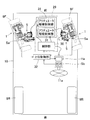
- the steering system includes a hub unit 1 with a steering function and a control device 29 that controls the steering actuator 5 of the hub unit 1 with a steering function.
- the control device 29 includes a control unit 30 and an actuator drive control unit 31.
- the driver operates the steering angle of the wheel with the steering wheel, and the upper control unit 32 outputs a steering angle command signal e for the left and right wheels calculated in consideration of the vehicle condition and the like according to the steering wheel operating angle.
- the control unit 30 outputs a current command signal f corresponding to the steering angle command signal e given from the host control unit 32.
- the upper control unit 32 is an upper control means of the control unit 30, and an electric control unit (Vehicle Control Unit, abbreviated as VCU) for controlling the entire vehicle is applied as the upper control unit 32, for example.
- VCU Electric Control Unit
- the actuator drive control unit 31 drives and controls the steering actuator 5 by outputting a drive current g corresponding to the current command signal f input from the control unit 30.
- the actuator drive control unit 31 controls the power supplied to the coil of the motor 26.
- the actuator drive control unit 31 configures, for example, a half bridge circuit using a switch element (not shown), and performs PWM control for determining a motor applied voltage based on the ON-OFF duty ratio of the switch element.
- the angle of the wheel can be changed by changing the angle of the hub unit main body 2 with respect to the unit support member 3. Even when running straight, the amount of toe angle can be adjusted to suit each scene. Therefore, it is possible to improve athletic performance and fuel consumption.
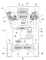
- the steering function-equipped hub unit 1 may be mounted on the left and right front wheels 9F, 9F and the left and right rear wheels 9R, 9R.
- the toe angle adjustment during traveling is effective, and the minimum turning radius during low-speed traveling can be reduced.
- SYMBOLS 1 Hub unit with a steering function
- 2 ... Hub unit main body, 3 ... Unit support member, 4 ... Rolling bearing (rotation allowance support component), 5 ... Steering actuator, 6 ... Knuckle (suspension frame component), 9 ... Wheel , 9F ... front wheel, 9R ... rear wheel, 10 ... vehicle, 11a ... steering input unit, 12 ... suspension device, 15 ... hub bearing, 29 ... control device, 30 ... control unit, 31 ... actuator drive control unit
Landscapes
- Engineering & Computer Science (AREA)
- Mechanical Engineering (AREA)
- General Engineering & Computer Science (AREA)
- Chemical & Material Sciences (AREA)
- Combustion & Propulsion (AREA)
- Transportation (AREA)
- Physics & Mathematics (AREA)
- Mathematical Physics (AREA)
- Power Steering Mechanism (AREA)
- Steering-Linkage Mechanisms And Four-Wheel Steering (AREA)
- Steering Control In Accordance With Driving Conditions (AREA)
Abstract
構造が簡単であり、高剛性で且つ小型化を図れる操舵機能付ハブユニット、操舵システム、および操舵機能付ハブユニットを備えた車両を提供する。この操舵機能付ハブユニット(1)は、車輪(9)を支持するハブベアリング(15)を有するハブユニット本体(2)と、懸架装置(12)のナックル(6)に設けられ、ハブユニット本体(2)を上下方向に延びる転舵軸心(A)回りに回転自在に支持するユニット支持部材(3)と、ハブユニット本体(2)を転舵軸心(A)回りに回転駆動させる操舵用アクチュエータ(5)とを備える。ハブユニット本体(2)は、予圧を与えられた転がり軸受(4,4)を介してユニット支持部材(3)に支持されている。
Description
この出願は、2018年3月27日出願の特願2018-059174の優先権を主張するものであり、その全体を参照によりこの出願の一部をなすものとして引用する。
この発明は、操舵機能付ハブユニット、操舵システム、および操舵機能付ハブユニットを備えた車両に関し、燃費の改善、車両の走行性の安定と信頼性の向上を図る技術に関する。
一般的な自動車等の車両は、ハンドルとステアリング装置が機械的に接続され、また、ステアリング装置の両端はタイロッドによってそれぞれの左右輪につながっている。そのため、ハンドルの動きによる左右輪の切れ角度は初期の設定によって決まる。車両のジオメトリには、(1) 左右輪の切れ角度が同じである「パラレルジオメトリ」、(2) 旋回中心を1か所にするために旋回内輪車輪角度を旋回外輪車輪角度よりも大きく切る「アッカーマンジオメトリ」が知られている。
アッカーマンジオメトリは、車両に作用する遠心力を無視できるような低速域での旋回において、車輪をスムースに旋回させるために、各輪が共通の一点を中心として旋回するように左右輪の舵角差を設定している。しかし、遠心力を無視できない高速域の旋回においては、車輪は遠心力とつり合う方向にコーナリングフォースを発生させることが望ましいため、アッカーマンジオメトリよりもパラレルジオメトリとすることが好ましい。
前述したように一般的な車両の操舵装置は機械的に車輪と接続されているため、一般的には固定された単一のステアリングジオメトリしか取ることができず、アッカーマンジオメトリとパラレルジオメトリとの中間的なジオメトリに設定されることが多い。しかし、この場合、低速域では左右輪の舵角差が不足して外輪の舵角が過大となり、高速域では内輪の舵角が過大となる。このように内外輪の車輪横力配分に不要な偏りがあると、走行抵抗の悪化による燃費悪化および車輪の早期摩耗の原因となり、また内外輪を効率的に利用できないことによって、コーナリングのスムースさが損なわれるといった課題がある。
[特許文献1]
特許文献1などに代表されるステアバイワイヤシステム(装置)は、ハンドルの舵角を検出するための舵角センサと、ステアリングシャフトに実際にかかる操舵反力を検出するためのトルクセンサとが備えられており、これらのセンサ信号を利用してステアリング装置のアクチュエータを操作し、左右の車輪を1つのステアリング装置で操舵させている。この場合、シャーシのフロント部に配置されるステアリング装置には、大きなモータが組み込まれ、システム全体が大きくなる。シャーシのフロント部はエンジン・トランスミッションなどの他の機構部が多く、スペースには限りがある。
特許文献1などに代表されるステアバイワイヤシステム(装置)は、ハンドルの舵角を検出するための舵角センサと、ステアリングシャフトに実際にかかる操舵反力を検出するためのトルクセンサとが備えられており、これらのセンサ信号を利用してステアリング装置のアクチュエータを操作し、左右の車輪を1つのステアリング装置で操舵させている。この場合、シャーシのフロント部に配置されるステアリング装置には、大きなモータが組み込まれ、システム全体が大きくなる。シャーシのフロント部はエンジン・トランスミッションなどの他の機構部が多く、スペースには限りがある。
[特許文献2]
前輪または後輪系統の各輪を独立に操舵可能なステアリングアクチュエータを作動させるステアリングシステムであるが、このステアリングアクチュエータはシャーシに固定されており、特許文献1と同様にスペースの確保が難しい。また、運転条件に合わせて、左右を独立して別々に車輪角度を自由に制御できるが、ステアリングアクチュエータがシャーシに固定されているうえに、ステアリングアクチュエータと車輪を連結しているタイロッドの長さが一定であるため、コーナリング時など車両がタイヤに対して沈み込むような状況、もしくは浮き上がるような状況では、車輪角度が大きく変化し、所定の角度に調整することは難しい。
前輪または後輪系統の各輪を独立に操舵可能なステアリングアクチュエータを作動させるステアリングシステムであるが、このステアリングアクチュエータはシャーシに固定されており、特許文献1と同様にスペースの確保が難しい。また、運転条件に合わせて、左右を独立して別々に車輪角度を自由に制御できるが、ステアリングアクチュエータがシャーシに固定されているうえに、ステアリングアクチュエータと車輪を連結しているタイロッドの長さが一定であるため、コーナリング時など車両がタイヤに対して沈み込むような状況、もしくは浮き上がるような状況では、車輪角度が大きく変化し、所定の角度に調整することは難しい。
[特許文献3]
転舵軸に対しハブベアリングを片持ち支持しているため、剛性が低下し、走行Gによってステアリングジオメトリが変化してしまう可能性がある。また、転舵軸上に減速機を設けた場合、モータを含めて機構全体のサイズが大きくなる。機構全体のサイズが大きくなると車輪の内周部に機構全体を配置することが困難となる。また、減速比の大きい減速機を設けた場合、応答性が低下する。
転舵軸に対しハブベアリングを片持ち支持しているため、剛性が低下し、走行Gによってステアリングジオメトリが変化してしまう可能性がある。また、転舵軸上に減速機を設けた場合、モータを含めて機構全体のサイズが大きくなる。機構全体のサイズが大きくなると車輪の内周部に機構全体を配置することが困難となる。また、減速比の大きい減速機を設けた場合、応答性が低下する。
上記のように従来の車輪毎に操舵機能を備えた機構は、シャーシのフロント部分におけるステアリング装置に必要なスペースを低減できるが、車両において車輪のトー角またはキャンバー角を変更することを目的としているため、モータおよび減速機構が複数必要になり複雑な構成となっている。また、剛性を確保することが困難であり、剛性を確保するためには大型とする必要があり重くなる。また、キングピン軸と転舵軸が一致する場合は、構成要素部品がハブユニットの後方(車体側)に配置されるために全体のサイズが大きくなり重くなる。
[特許文献4]
これらのアクチュエータは走行中には車輪から常に荷重を受ける必要があり、ウォームなど歯車を使った構造の場合、車輪側から逆入力される荷重はこの歯車部で受けることとなる。路面状況が悪い場合には急激な衝撃荷重を車輪が受けることがあり、これらの荷重を受けている歯車に異常が生じる可能性がある。
これらのアクチュエータは走行中には車輪から常に荷重を受ける必要があり、ウォームなど歯車を使った構造の場合、車輪側から逆入力される荷重はこの歯車部で受けることとなる。路面状況が悪い場合には急激な衝撃荷重を車輪が受けることがあり、これらの荷重を受けている歯車に異常が生じる可能性がある。
全輪駆動(略称;AWD)、FF、FRの車両は通常、フロントにエンジンとトランスミッションなどを備えており、フロントのシャーシ内部空間は場所の取り合いになっており、各部品には小型化が求められている。前輪を操舵するステアリング装置も同様な場所に配置されるため、複雑で大きな機構では採用が難しい。また、ハンドルからステアリング装置および車輪が機械的に連結されていると、砂利道または石畳など、悪路を走行した場合にタイヤが受けた振動が運転者にとって不快な振動として伝達される。
シャーシ側を広く余裕をもたせるために、ホイール内に配置された機構で、車輪のトー角またはキャンバー角を変更するためには、複雑な構成が必要で、構成部品が多くなり剛性が低下してしまう。
この発明の目的は、構造が簡単であり、高剛性で且つ小型化を図れる操舵機能付ハブユニット、操舵システム、および操舵機能付ハブユニットを備えた車両を提供することである。
この発明の操舵機能付ハブユニットは、操舵入力部と車輪とが機械的に分離され且つ前記車輪を操舵させるステアバイワイヤシステムに用いる操舵機能付きハブユニットであって、前記車輪を支持するハブベアリングを有するハブユニット本体と、懸架装置の足回りフレーム部品に設けられ、前記ハブユニット本体を上下方向に延びる転舵軸心回りに回転自在に支持するユニット支持部材と、前記ハブユニット本体を前記転舵軸心回りに回転駆動させる前記操舵用アクチュエータと、を備え、前記ハブユニット本体は、予圧を与えられた転がり軸受を介して前記ユニット支持部材に支持されている。前記予圧は、例えば、車両の重量がハブユニットに作用した場合でも初期予圧が抜けないように設定されている。
この構成によると、車輪を支持するハブベアリングを含むハブユニット本体を、操舵用アクチュエータの駆動により、前記転舵軸心回りに自由に回転させることができる。このため、車輪毎に独立して操舵が行え、また車両の走行状況に応じて、車輪のトー角を任意に変更することができる。ハブユニット本体が、予圧を与えられた転がり軸受を介してユニット支持部材に支持されたため、この操舵機能付きハブユニットはステアリング装置としての剛性を確保することができる。
この構成を前輪に適用した場合、運転者のハンドル操作によって、前輪である車輪が操舵される。また車輪毎に独立して操舵を行える。前輪操舵付きの車両において、この構成を後輪に適用することができ、その場合、この後輪の操舵機能により、車両の回転半径を小さくし小回り性能を向上することが可能となる。後輪の操舵角を大きく確保する必要はないため、操舵用アクチュエータを小型化することができる。どちらの場合においても、前記操舵用アクチュエータにより、ハブユニット本体を転舵軸心回りに自由に回転させることができるため、車両の走行状況に応じて、例えば車輪のトー角を自由に左右独立して変更することができる。操舵機構をハブユニットに備えるため、シャーシフロント部の空間に余裕ができる。
また旋回走行時には、車両のセンサなどから得られる情報(車速、ハンドル角、横力など)に応じて、左右輪の舵角差を変更することで、例えば、高速域の旋回走行においてはパラレルジオメトリとし、低速域の旋回走行においてはアッカーマンジオメトリとするなど、走行中にステアリングジオメトリを変化させることも可能である。このように走行中に車輪の操舵角度を自由に変更することができるため、車両の運動性能を向上させると共に、高い安定性と信頼性で走行することも可能となる。
さらに、左右の操舵輪の操舵角度を適切に変えることで、旋回走行における車両の旋回半径を小さくし、小回り性能を向上させることもできる。さらに直線走行時にも、それぞれの場面に合わせてトー角を調整することで、燃費を低下させることなく、走行安定性を確保するなど調整が可能である。また、ハンドルなどの操舵入力部と車輪とが機械的に連結されていないため、砂利道または石畳などを走行する場合など、運転者にとって不快な振動を遮断することができる。運転者にとって必要な情報のみを操舵入力部の例えば反力アクチュエータなどから運転者に伝達することも可能である。
この発明の操舵システムは、この発明の前記構成の操舵機能付きハブユニットと、この操舵機能付ハブユニットの転動用アクチュエータを制御する制御装置とを備えた操舵システムであって、前記制御装置は、与えられた操舵角指令信号に応じた電流指令信号を出力する制御部と、この制御部から入力された電流指令信号に応じた駆動電流を出力して前記転動用アクチュエータを駆動制御するアクチュエータ駆動制御部とを有する。
この構成によると、制御部は、与えられた操舵角指令信号に応じた電流指令信号を出力する。アクチュエータ駆動制御部は、制御部から入力された電流指令信号に応じた電流を出力して転動用アクチュエータを駆動制御する。したがって、運転者の操舵入力部の操作による操舵に付加して車輪の操舵角度を任意に変更することができる。
この発明における第1の発明の車両は、この発明の前記構成の操舵機能付ハブユニットを左右の前輪に装備したものである。この発明における第2の発明の車両は、この発明の前記構成の操舵機能付ハブユニットを左右の後輪に装備したものである。この発明における第3の発明の車両は、この発明の前記構成の操舵機能付ハブユニットを左右の前輪および左右の後輪に装備したものである。
そのため、この発明の操舵機能付ハブユニットにつき前述した各効果が得られる。前輪は一般的に操舵輪とされるが、操舵輪にこの発明の操舵機能付ハブユニットを適用した場合は、走行中におけるトー角調整に効果的である。また、後輪は一般的に非操舵輪とされるが、非操舵輪に適用した場合は、非操舵輪の若干の操舵によって低速走行時における最小回転半径の低減を図ることができる。この操舵機能付ハブユニットを前後輪に適用した場合は、走行中におけるトー角調整に効果的であり、また低速走行時における最小回転半径の低減を図ることができる。
請求の範囲および/または明細書および/または図面に開示された少なくとも2つの構成のどのような組み合わせも、この発明に含まれる。特に、請求の範囲の各請求項の2つ以上のどのような組み合わせも、この発明に含まれる。
この発明は、添付の図面を参考にした以下の好適な実施形態の説明から、より明確に理解されるであろう。しかしながら、実施形態および図面は単なる図示および説明のためのものであり、この発明の範囲を定めるために利用されるべきものではない。この発明の範囲は添付の請求の範囲によって定まる。添付図面において、複数の図面における同一の符号は、同一または相当する部分を示す。
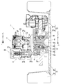
この発明の第1実施形態に係る操舵機能付ハブユニットおよびその周辺の構成を示す縦断面図である。
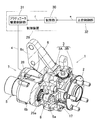
同操舵機能付ハブユニットおよびその周辺の構成を示す水平断面図である。
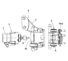
同操舵機能付ハブユニットの外観を示す斜視図である。
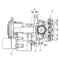
同操舵機能付ハブユニットの分解正面図である。
同操舵機能付ハブユニットの側面図である。
同操舵機能付ハブユニットの平面図である。
図5のVII - VII線断面図である。
左に操舵させた同操舵機能付ハブユニットの水平断面図である。
右に操舵させた同操舵機能付ハブユニットの水平断面図である。
同操舵機能付ハブユニットを備えた車両の一例の模式平面図である。
同操舵機能付ハブユニットを備えた車両の他の例の模式平面図である。
同操舵機能付ハブユニットを備えた車両のさらに他の例の模式平面図である。
<第1実施形態>
この発明の第1実施形態に係る操舵機能付ハブユニットを図1ないし図10と共に説明する。この操舵機能付ハブユニットは、ハンドルである操舵入力部と車輪とが機械的に分離され、且つ前記車輪を操舵させるステアバイワイヤシステムに適用する。
この発明の第1実施形態に係る操舵機能付ハブユニットを図1ないし図10と共に説明する。この操舵機能付ハブユニットは、ハンドルである操舵入力部と車輪とが機械的に分離され、且つ前記車輪を操舵させるステアバイワイヤシステムに適用する。
<操舵機能付ハブユニット1の概略構造>
図1に示すように、この操舵機能付ハブユニット1は、ハブユニット本体2と、ユニット支持部材3と、回転許容支持部品である転がり軸受4と、操舵用アクチュエータ5とを備える。足回りフレーム部品であるナックル6に一体にユニット支持部材3が設けられている。この例のナックル6は、操舵方向には回転しないよう固定されており、通常の懸架装置12に取り付けられている。したがって、この操舵機能付ハブユニット1を装備した車両の車輪9の操舵は、操舵用アクチュエータ5の動作のみで決定される。この操舵機能付ハブユニット1は、ハンドル操作により車輪9の操舵に加えて、左右の車輪9の角度を、独立して変化させるのに使用される。
図1に示すように、この操舵機能付ハブユニット1は、ハブユニット本体2と、ユニット支持部材3と、回転許容支持部品である転がり軸受4と、操舵用アクチュエータ5とを備える。足回りフレーム部品であるナックル6に一体にユニット支持部材3が設けられている。この例のナックル6は、操舵方向には回転しないよう固定されており、通常の懸架装置12に取り付けられている。したがって、この操舵機能付ハブユニット1を装備した車両の車輪9の操舵は、操舵用アクチュエータ5の動作のみで決定される。この操舵機能付ハブユニット1は、ハンドル操作により車輪9の操舵に加えて、左右の車輪9の角度を、独立して変化させるのに使用される。
図4に示すように、このユニット支持部材3のインボード側に、操舵用アクチュエータ5のアクチュエータ本体7が設けられ、ユニット支持部材3のアウトボード側に、ハブユニット本体2が設けられる。操舵機能付ハブユニット1(図1)を車両に搭載した状態で、車両の車幅方向外側をアウトボード側といい、車両の車幅方向中央側をインボード側という。
図2および図3に示すように、ハブユニット本体2とアクチュエータ本体7とはジョイント部8により連結されている。通常、このジョイント部8は、防水、防塵のために図示外のブーツが取り付けられている。このジョイント部8には、後述する反力センサSaが設けられている。
図1に示すように、ハブユニット本体2は、上下方向に延びる転舵軸心A回りに回転自在なように、上下二箇所で転がり軸受4,4を介してユニット支持部材3に支持されている。転舵軸心Aは、車輪9の回転軸心Oとは異なる軸心である。車輪9は、ホイール9aとタイヤ9bとを備える。
<操舵機能付ハブユニット1の設置箇所>
図3および図10に示すように、操舵機能付ハブユニット1は、懸架装置12(図1)のナックル6に設けられ、且つ、車両10における操舵輪である左右の前輪9F,9Fにそれぞれ装備されている。懸架装置12(図1)は、例えば、ショックアブソーバーをナックル6に直接固定するストラット式サスペンション機構を適用しているが、マルチリンク式サスペンション機構、その他のサスペンション機構を適用してもよい。
図3および図10に示すように、操舵機能付ハブユニット1は、懸架装置12(図1)のナックル6に設けられ、且つ、車両10における操舵輪である左右の前輪9F,9Fにそれぞれ装備されている。懸架装置12(図1)は、例えば、ショックアブソーバーをナックル6に直接固定するストラット式サスペンション機構を適用しているが、マルチリンク式サスペンション機構、その他のサスペンション機構を適用してもよい。
ステアバイワイヤシステムでは、操舵機能付ハブユニット1と、ハンドルである操舵入力部11aは、機械的に連結されておらず、電気信号でのみ電気的に接続されている。操舵入力部11aには、運転者のハンドル操作による回転角および角速度を検出し出力するセンサSbが設けられている。ステアバイワイヤシステムは、このセンサSbから出力された電気信号に基づいて操舵用アクチュエータ5,5を動作させ、車両10の走行条件に合わせて、左右の前輪9F,9Fを独立して自由に操舵させる。
前記センサSbとして、回転角を検出する例えばレゾルバ等の回転角検出手段を採用し得る。前記角速度は、回転角検出手段で検出した回転角を微分する等して求められる。ステアバイワイヤシステムは、タイヤからの反力を検出する反力センサSaと、この反力センサSaで検出する反力から運転者に必要な情報(操舵反力)のみ操舵入力部11aに与える反力アクチュエータHaとを有する。
反力センサSaは、ジョイント部8に作用する反力を検出するセンサであって、例えば、ロードセルまたは荷重センサ等が適用される。この場合、操舵用アクチュエータ5の直動出力部25aが進退することで、反力センサSaは、直動出力部25aに与えられる軸方向の力を検出し電気信号に変換する。この反力センサSaで得られる電気信号と、反力アクチュエータHaで生成する操舵反力との関係は、例えば、マップまたは演算式等に定められている。したがって、このステアバイワイヤシステムによれば、車両状況に応じた操舵感を実現し得る。ステアバイワイヤシステムは、前記運転者のハンドル操作に代えて、図示外の自動運転装置、運転支援装置の指令等によって操舵用アクチュエータ5,5を動作させてもよい。
<ハブユニット本体2について>
図1および図7に示すように、ハブユニット本体2は、車輪9の支持用のハブベアリング15と、アウターリング16と、後述の操舵力受け部であるアーム部17(図3)とを備える。ハブベアリング15は、内輪18と、外輪19と、これら内外輪18,19間に介在したボール等の転動体20とを有し、車体側の部材と車輪9とを繋ぐ役目をしている。
図1および図7に示すように、ハブユニット本体2は、車輪9の支持用のハブベアリング15と、アウターリング16と、後述の操舵力受け部であるアーム部17(図3)とを備える。ハブベアリング15は、内輪18と、外輪19と、これら内外輪18,19間に介在したボール等の転動体20とを有し、車体側の部材と車輪9とを繋ぐ役目をしている。
このハブベアリング15は、図示の例では、外輪19が固定輪、内輪18が回転輪となり、転動体20が複列とされたアンギュラ玉軸受とされている。内輪18は、ハブフランジ18aaを有しアウトボード側の軌道面を構成するハブ輪部18aと、インボード側の軌道面を構成する内輪部18bとを有する。ハブフランジ18aaに、車輪9のホイール9aがブレーキロータ21aと重なり状態でボルト固定されている。内輪18は、回転軸心O回りに回転する。
アウターリング16は、外輪19の外周面に嵌合された円環部16aと、この円環部16aの外周から上下に突出して設けられたトラニオン軸状の取付軸部16b,16bとを有する。各取付軸部16bは、転舵軸心Aに同軸に設けられる。図2に示すように、ブレーキ21は、ブレーキロータ21aと、ブレーキキャリパ21bとを有する。ブレーキキャリパ21bは、外輪19に一体にアーム状に突出して形成された上下二箇所のブレーキキャリパ取付部22(図5)に取付けられる。
<回転許容支持部品4およびユニット支持部材3について>
図7に示すように、各回転許容支持部品である転がり軸受4として、テーパころ軸受が適用されている。この例では、転がり軸受(回転許容支持部品)4としてテーパころ軸受が適用されている。転がり軸受4は、取付軸部16bの外周に嵌合された内輪4aと、ユニット支持部材3に嵌合された外輪4bと、内外輪4a,4b間に介在する複数の転動体4cとを有する。
図7に示すように、各回転許容支持部品である転がり軸受4として、テーパころ軸受が適用されている。この例では、転がり軸受(回転許容支持部品)4としてテーパころ軸受が適用されている。転がり軸受4は、取付軸部16bの外周に嵌合された内輪4aと、ユニット支持部材3に嵌合された外輪4bと、内外輪4a,4b間に介在する複数の転動体4cとを有する。
ユニット支持部材3は、ユニット支持部材本体3Aと、ユニット支持部材結合体3Bとを有する。ユニット支持部材本体3Aのアウトボード側端に、略リング形状のユニット支持部材結合体3Bが着脱自在に固定されている。ユニット支持部材結合体3Bのインボード側側面のうち上下の部分には、部分的な凹球面状の嵌合孔形成部3aがそれぞれ形成されている。
図6および図7に示すように、ユニット支持部材本体3Aのアウトボード側端のうち上下の部分には、部分的な凹球面状の嵌合孔形成部3Aaがそれぞれ形成されている。図3に示すように、ユニット支持部材本体3Aのアウトボード側端にユニット支持部材結合体3Bが固定されている。前記各上下の部分につき、嵌合孔形成部3a,3Aa(図6)が互いに組み合わされることにより、全周に連なる嵌合孔が形成される。図7に示すように、この嵌合孔に外輪4bが嵌合されている。なお、図3において、ユニット支持部材3を一点鎖線で表す。
図7に示すように、アウターリング16における各取付軸部16bには、雌ねじ部が径方向に延びるように形成され、この雌ねじ部に螺合するボルト23が設けられている。内輪4aの端面に円板状の押圧部材24を介在させ、前記雌ねじ部に螺合するボルト23により、内輪4aの端面に押圧力を付与することで、各転がり軸受4にそれぞれ予圧を与えている。これにより各転がり軸受4の剛性を高め得る。車両の重量がこのハブユニットに作用した場合でも初期予圧が抜けないように設定される。このため、この操舵機能付きハブユニットはステアリング装置としての剛性を確保することができる。なお、転がり軸受4は、テーパころ軸受に限るものではなく、最大負荷等の使用条件によってはアンギュラ玉軸受を用いることも可能である。その場合も、上記と同様に予圧を与えることができる。
図2に示すように、アーム部17は、ハブベアリング15の外輪19に操舵力を与える作用点となる部位であり、外輪19の外周の一部に一体に突出する。このアーム部17は、ジョイント部8を介して、操舵用アクチュエータ5の直動出力部25aに回転自在に連結されている。これにより、操舵用アクチュエータ5の直動出力部25aが進退することで、ハブユニット本体2が転舵軸心A(図1)回りに回転、つまり操舵させられる。図8、図9に、それぞれ左旋回時、右旋回時の右車輪9の様子を示す。後述する操舵用アクチュエータ5の直動機構25をモータ26によって前後することで車輪9の操舵角を変更している。
<操舵用アクチュエータ5>
図3に示すように、操舵用アクチュエータ5は、ハブユニット本体2を転舵軸心A(図1)回りに回転駆動させるアクチュエータ本体7を有する。図2に示すように、アクチュエータ本体7は、モータ26と、モータ26の回転を減速する減速機27と、この減速機27の正逆の回転出力を直動出力部25aの往復直線動作に変換する直動機構25とを備える。モータ26は、例えば永久磁石型同期モータとされるが、直流モータであっても、誘導モータであってもよい。減速機27は省略される場合もある。
図3に示すように、操舵用アクチュエータ5は、ハブユニット本体2を転舵軸心A(図1)回りに回転駆動させるアクチュエータ本体7を有する。図2に示すように、アクチュエータ本体7は、モータ26と、モータ26の回転を減速する減速機27と、この減速機27の正逆の回転出力を直動出力部25aの往復直線動作に変換する直動機構25とを備える。モータ26は、例えば永久磁石型同期モータとされるが、直流モータであっても、誘導モータであってもよい。減速機27は省略される場合もある。
減速機27は、ベルト伝達機構等の巻き掛け式伝達機構またはギヤ列等を用いることができ、図2の例ではベルト伝達機構が用いられている。減速機27は、ドライブプーリ27aと、ドリブンプーリ27bと、ベルト27cとを有する。モータ26のモータ軸にドライブプーリ27aが結合され、直動機構25にドリブンプーリ27bが設けられている。このドリブンプーリ27bは、前記モータ軸に平行に配置されている。モータ26の駆動力は、ドライブプーリ27aからベルト27cを介してドリブンプーリ27bに伝達される。前記各ドライブプーリ27aとドリブンプーリ27bとベルト27cとで、巻き掛け式の減速機27が構成される。
直動機構25は、滑りねじまたはボールねじ等の送りねじ機構、またはラック・ピニオン機構等を用いることができ、この例では台形ねじの滑りねじを用いた送りねじ機構が用いられている。直動機構25は、前記台形ねじの滑りねじを用いた送りねじ機構を備えるため、タイヤ9bからの逆入力の防止効果を高め得る。モータ26、減速機27および直動機構25を備えたアクチュエータ本体7は、準組立品として組み立てられてケース6bにボルト等により着脱自在に取り付けられる。なお、モータ26の駆動力を、減速機を介さず直接直動機構25へ伝達する機構も可能である。
ケース6bは、ユニット支持部材3の一部として、ユニット支持部材本体3Aに一体に形成されている。ケース6bは、有底筒状に形成され、モータ26を支持するモータ収容部と、直動機構25を支持する直動機構収容部が設けられている。前記モータ収容部には、モータ26をケース内所定位置に支持する嵌合孔が形成されている。前記直動機構収容部には、直動機構25をケース内所定位置に支持する嵌合孔、および、直動出力部25aの進退を許す貫通孔等が形成されている。
図3に示すように、ユニット支持部材本体3Aは、前記ケース6b、およびショックアブソーバの取り付け部となるショックアブソーバ取り付け部6cを有する。このショックアブソーバ取り付け部6cも、ユニット支持部材本体3Aに一体に形成されている。ユニット支持部材本体3Aの外表面部における上部に、ショックアブソーバ取り付け部6cが突出するように形成されている。
<作用効果>
以上説明した操舵機能付ハブユニット1によれば、車輪9を支持するハブベアリング15を含むハブユニット本体2を、操舵用アクチュエータ5の駆動により、前記転舵軸心A回りに自由に回転させることができる。このため、車輪毎に独立して操舵が行え、また車両10の走行状況に応じて、車輪9のトー角を任意に変更することができる。ハブユニット本体2が、予圧を与えられた転がり軸受4,4を介してユニット支持部材3に支持されたため、この操舵機能付きハブユニット1はステアリング装置としての剛性を確保することができる。
以上説明した操舵機能付ハブユニット1によれば、車輪9を支持するハブベアリング15を含むハブユニット本体2を、操舵用アクチュエータ5の駆動により、前記転舵軸心A回りに自由に回転させることができる。このため、車輪毎に独立して操舵が行え、また車両10の走行状況に応じて、車輪9のトー角を任意に変更することができる。ハブユニット本体2が、予圧を与えられた転がり軸受4,4を介してユニット支持部材3に支持されたため、この操舵機能付きハブユニット1はステアリング装置としての剛性を確保することができる。
この構成を前輪9Fに適用した場合、運転者のハンドル操作によって、前輪9Fである車輪9が操舵される。また車輪毎に独立して操舵を行える。前輪操舵付きの車両において、この構成を後輪9R(図11)に適用することができ、その場合、この後輪9R(図11)の操舵機能により、車両の回転半径を小さくし小回り性能を向上することが可能となる。後輪9R(図11)の操舵角を大きく確保する必要はないため、操舵用アクチュエータを小型化することができる。
どちらの場合においても、前記操舵用アクチュエータ5により、ハブユニット本体2を転舵軸心A回りに自由に回転させることができるため、車両10の走行状況に応じて、例えば車輪9のトー角を自由に左右独立して変更することができる。操舵機構をハブユニット1に備えるため、シャーシフロント部の空間に余裕ができる。さらに操舵用アクチュエータ5をハブユニット1に配置したため、ステアリング装置を車幅方向に配置する必要がなく車両内のスペースを広く使える。
また旋回走行時には、車両10のセンサなどから得られる情報(車速、ハンドル角、横力など)に応じて、左右輪9,9の舵角差を変更することで、例えば、高速域の旋回走行においてはパラレルジオメトリとし、低速域の旋回走行においてはアッカーマンジオメトリとするなど、走行中にステアリングジオメトリを変化させることも可能である。このように走行中に車輪9の操舵角度を自由に変更することができるため、車両10の運動性能を向上させると共に、高い安定性と信頼性で走行することも可能となる。
さらに、左右の操舵輪の操舵角度を適切に変えることで、旋回走行における車両10の旋回半径を小さくし、小回り性能を向上させることもできる。さらに直線走行時にも、それぞれの場面に合わせてトー角を調整することで、燃費を低下させることなく、走行安定性を確保するなど調整が可能である。また、ハンドルなどの操舵入力部11aと車輪9とが機械的に連結されていないため、砂利道または石畳などを走行する場合など、運転者にとって不快な振動を遮断することができる。運転者にとって必要な情報のみを操舵入力部11aの例えば反力アクチュエータHaなどから運転者に伝達することも可能である。
<操舵システムについて>
図3に示すように、この操舵システムは、操舵機能付ハブユニット1と、この操舵機能付ハブユニット1の操舵用アクチュエータ5を制御する制御装置29とを備える。制御装置29は、制御部30と、アクチュエータ駆動制御部31とを有する。運転者はハンドルによって車輪の舵角を操作するが、上位制御部32ではハンドルの操作角に応じ、さらに車両の状況などを加味して算出した左右輪の操舵角指令信号eを出力する。制御部30は、上位制御部32から与えられた操舵角指令信号eに応じた電流指令信号fを出力する。
図3に示すように、この操舵システムは、操舵機能付ハブユニット1と、この操舵機能付ハブユニット1の操舵用アクチュエータ5を制御する制御装置29とを備える。制御装置29は、制御部30と、アクチュエータ駆動制御部31とを有する。運転者はハンドルによって車輪の舵角を操作するが、上位制御部32ではハンドルの操作角に応じ、さらに車両の状況などを加味して算出した左右輪の操舵角指令信号eを出力する。制御部30は、上位制御部32から与えられた操舵角指令信号eに応じた電流指令信号fを出力する。
前記上位制御部32は制御部30の上位の制御手段であり、この上位制御部32として、例えば、車両全般を制御する電気制御ユニット(Vehicle Control Unit,略称VCU)が適用される。アクチュエータ駆動制御部31は、制御部30から入力された電流指令信号fに応じた駆動電流gを出力して操舵用アクチュエータ5を駆動制御する。アクチュエータ駆動制御部31は、モータ26のコイルに供給する電力を制御する。このアクチュエータ駆動制御部31は、例えば、図示外のスイッチ素子を用いたハーフブリッジ回路を構成し、前記スイッチ素子のON-OFFデューティ比によりモータ印加電圧を決定するPWM制御を行う。これにより、ユニット支持部材3に対するハブユニット本体2の角度を変化させて車輪の角度を変化することができる。直線走行時にも、それぞれの場面に合わせてトー角の量を調整し得る。よって、運動性能および燃費向上を図ることができる。
図12に示すように、この操舵機能付ハブユニット1を左右の前輪9F,9Fおよび左右の後輪9R,9Rに装備してもよい。この場合、走行中におけるトー角調整に効果的であり、また低速走行時における最小回転半径の低減を図ることができる。
以上のとおり、図面を参照しながら好適な実施形態を説明したが、当業者であれば、本件明細書を見て、自明な範囲内で種々の変更および修正を容易に想定するであろう。したがって、そのような変更および修正は、請求の範囲から定まる発明の範囲内のものと解釈される。
1…操舵機能付ハブユニット、2…ハブユニット本体、3…ユニット支持部材、4…転がり軸受(回転許容支持部品)、5…操舵用アクチュエータ、6…ナックル(足回りフレーム部品)、9…車輪,9F…前輪,9R…後輪、10…車両、11a…操舵入力部、12…懸架装置、15…ハブベアリング、29…制御装置、30…制御部、31…アクチュエータ駆動制御部
Claims (5)
- 操舵入力部と車輪とが機械的に分離され且つ前記車輪を操舵させるステアバイワイヤシステムに用いる操舵機能付きハブユニットであって、
前記車輪を支持するハブベアリングを有するハブユニット本体と、
懸架装置の足回りフレーム部品に設けられ、前記ハブユニット本体を上下方向に延びる転舵軸心回りに回転自在に支持するユニット支持部材と、
前記ハブユニット本体を前記転舵軸心回りに回転駆動させる前記操舵用アクチュエータと、を備え、
前記ハブユニット本体は、予圧を与えられた転がり軸受を介して前記ユニット支持部材に支持された操舵機能付きハブユニット。 - 請求項1に記載の操舵機能付きハブユニットと、この操舵機能付ハブユニットの転動用アクチュエータを制御する制御装置とを備えた操舵システムであって、前記制御装置は、与えられた操舵角指令信号に応じた電流指令信号を出力する制御部と、この制御部から入力された電流指令信号に応じた駆動電流を出力して前記転動用アクチュエータを駆動制御するアクチュエータ駆動制御部とを有する操舵システム。
- 請求項1に記載の操舵機能付ハブユニットを左右の前輪に装備した車両。
- 請求項1に記載の操舵機能付ハブユニットを左右の後輪に装備した車両。
- 請求項1に記載の操舵機能付ハブユニットを左右の前輪および左右の後輪に装備した車両。
Priority Applications (3)
| Application Number | Priority Date | Filing Date | Title |
|---|---|---|---|
| EP19775319.7A EP3778355A4 (en) | 2018-03-27 | 2019-03-26 | STEERING, STEERING SYSTEM AND VEHICLE HUB UNIT |
| CN201980022347.7A CN111918810B (zh) | 2018-03-27 | 2019-03-26 | 线控系统和车辆 |
| US17/032,467 US11731693B2 (en) | 2018-03-27 | 2020-09-25 | Hub unit with steering function, steering system, and vehicle |
Applications Claiming Priority (2)
| Application Number | Priority Date | Filing Date | Title |
|---|---|---|---|
| JP2018-059174 | 2018-03-27 | ||
| JP2018059174A JP7244994B2 (ja) | 2018-03-27 | 2018-03-27 | 操舵機能付ハブユニット、操舵システム、および操舵機能付ハブユニットを備えた車両 |
Related Child Applications (1)
| Application Number | Title | Priority Date | Filing Date |
|---|---|---|---|
| US17/032,467 Continuation US11731693B2 (en) | 2018-03-27 | 2020-09-25 | Hub unit with steering function, steering system, and vehicle |
Publications (1)
| Publication Number | Publication Date |
|---|---|
| WO2019189103A1 true WO2019189103A1 (ja) | 2019-10-03 |
Family
ID=68061665
Family Applications (1)
| Application Number | Title | Priority Date | Filing Date |
|---|---|---|---|
| PCT/JP2019/012728 Ceased WO2019189103A1 (ja) | 2018-03-27 | 2019-03-26 | 操舵機能付ハブユニット、操舵システムおよび車両 |
Country Status (5)
| Country | Link |
|---|---|
| US (1) | US11731693B2 (ja) |
| EP (1) | EP3778355A4 (ja) |
| JP (1) | JP7244994B2 (ja) |
| CN (1) | CN111918810B (ja) |
| WO (1) | WO2019189103A1 (ja) |
Cited By (4)
| Publication number | Priority date | Publication date | Assignee | Title |
|---|---|---|---|---|
| CN111806555A (zh) * | 2020-06-03 | 2020-10-23 | 中国北方车辆研究所 | 推拉缸置于单纵臂悬架单纵臂上的独立转向系统 |
| US11772487B2 (en) | 2018-10-04 | 2023-10-03 | Ronald A. Holland | Vehicle rear drive axle |
| CN117207770A (zh) * | 2022-06-03 | 2023-12-12 | 现代摩比斯株式会社 | 用于车辆的角模块装置 |
| US20240286679A1 (en) * | 2021-06-28 | 2024-08-29 | Robert Bosch Gmbh | Method for Adjusting a Track of at least one Vehicle Wheel |
Families Citing this family (5)
| Publication number | Priority date | Publication date | Assignee | Title |
|---|---|---|---|---|
| JP7138526B2 (ja) * | 2018-09-28 | 2022-09-16 | Ntn株式会社 | 操舵機能付ハブユニットおよびこれを備えた車両 |
| CN111806553A (zh) * | 2020-06-03 | 2020-10-23 | 中国北方车辆研究所 | 转向电机置于单纵臂悬架单纵臂上的独立转向系统 |
| CN112172914B (zh) * | 2020-12-03 | 2021-02-12 | 山东悍沃农业装备有限公司 | 一种用于电动拖拉机的动力转向控制机构及其使用方法 |
| JP2022114979A (ja) * | 2021-01-27 | 2022-08-08 | Ntn株式会社 | 操舵機能付ハブユニット、操舵システムおよび車両 |
| JP7846548B2 (ja) * | 2022-03-23 | 2026-04-15 | 株式会社Subaru | 車両の操舵装置 |
Citations (9)
| Publication number | Priority date | Publication date | Assignee | Title |
|---|---|---|---|---|
| JPS5615094B2 (ja) | 1973-08-27 | 1981-04-08 | ||
| JP2005349845A (ja) | 2004-06-08 | 2005-12-22 | Toyoda Mach Works Ltd | ステアバイワイヤシステム |
| JP2007062628A (ja) * | 2005-09-01 | 2007-03-15 | Ntn Corp | 懸架装置の支持構造 |
| JP4230947B2 (ja) | 2004-03-22 | 2009-02-25 | 株式会社日立製作所 | 車両制御装置 |
| JP3158339U (ja) * | 2010-01-14 | 2010-03-25 | 株式会社キャロッセ | キングピンベアリングの与圧調整機構 |
| DE102012206337A1 (de) | 2012-04-18 | 2013-10-24 | Schaeffler Technologies AG & Co. KG | Gelenkige Lagerung eines Radlagers zur Sturz- und/oder Spurverstellung |
| JP2014061744A (ja) * | 2012-09-20 | 2014-04-10 | Jtekt Corp | 転舵装置および車両 |
| JP5615094B2 (ja) * | 2010-08-25 | 2014-10-29 | Ntn株式会社 | ステアバイワイヤ式操舵装置 |
| JP2018024284A (ja) * | 2016-08-08 | 2018-02-15 | 株式会社豊田中央研究所 | ステアバイワイヤ式操舵装置 |
Family Cites Families (33)
| Publication number | Priority date | Publication date | Assignee | Title |
|---|---|---|---|---|
| DE1806566C3 (de) * | 1968-11-02 | 1978-07-13 | Dr.Ing.H.C. F. Porsche Ag, 7000 Stuttgart | Befestigungsvorrichtung für ein Rad an einer Nabe bei Kraftfahrzeugen |
| JP3158339B2 (ja) | 1995-11-14 | 2001-04-23 | 株式会社ユニシアジェックス | 内燃機関の排気還流装置の故障診断装置 |
| US6364426B1 (en) * | 1998-08-05 | 2002-04-02 | Kelsey-Hayes Company | Vehicle wheel hub and bearing unit assembly and method for producing same |
| JP3934367B2 (ja) * | 2001-07-03 | 2007-06-20 | アルプス電気株式会社 | バイワイヤ方式のステアリング装置 |
| US6678596B2 (en) * | 2002-05-21 | 2004-01-13 | Visteon Global Technologies, Inc. | Generating steering feel for steer-by-wire systems |
| JP4292054B2 (ja) | 2003-11-06 | 2009-07-08 | 本田技研工業株式会社 | 車両用操舵装置 |
| JP4806930B2 (ja) | 2004-12-22 | 2011-11-02 | 日産自動車株式会社 | 車両用操舵装置 |
| JP4724075B2 (ja) * | 2006-08-29 | 2011-07-13 | 本田技研工業株式会社 | ホイール回転装置 |
| JP2008168744A (ja) | 2007-01-10 | 2008-07-24 | Fuji Heavy Ind Ltd | 左右独立操舵装置 |
| EP1975041B1 (en) * | 2007-03-27 | 2013-10-16 | Honda Motor Co., Ltd. | Steering system |
| JP5226999B2 (ja) | 2007-11-02 | 2013-07-03 | 富士重工業株式会社 | 車両の操舵装置 |
| DE102008003646A1 (de) * | 2008-01-09 | 2009-07-16 | GM Global Technology Operations, Inc., Detroit | Radnabengelenkeinheit für ein Fahrzeug |
| JP2009226972A (ja) | 2008-03-19 | 2009-10-08 | Fuji Heavy Ind Ltd | ジオメトリ可変装置 |
| JP5386103B2 (ja) * | 2008-04-17 | 2014-01-15 | ニチユ三菱フォークリフト株式会社 | 車両のステアリング制御装置 |
| JP2010179678A (ja) | 2009-02-03 | 2010-08-19 | Honda Motor Co Ltd | 路面摩擦係数推定装置 |
| JP5332982B2 (ja) | 2009-07-08 | 2013-11-06 | 日産自動車株式会社 | 車両用制御装置 |
| EP2554408B1 (en) | 2010-03-31 | 2017-08-09 | Equos Research Co., Ltd. | Camber angle adjustment device |
| JP5697966B2 (ja) * | 2010-12-20 | 2015-04-08 | Ntn株式会社 | ステアバイワイヤの操舵反力制御装置 |
| CN102069843B (zh) * | 2011-01-05 | 2012-11-07 | 吉林大学 | 线控车轮独立转向执行机构及车轮总成 |
| CN203094172U (zh) * | 2012-12-24 | 2013-07-31 | 中国科学院深圳先进技术研究院 | 一种独立转向与驱动电动汽车的线控转向装置及其悬架系统 |
| JP6050156B2 (ja) | 2013-03-11 | 2016-12-21 | 川崎重工業株式会社 | 案内軌条式車両用案内装置、及び案内軌条式車両 |
| JP6351944B2 (ja) | 2013-09-26 | 2018-07-04 | Ntn株式会社 | ステアリング装置 |
| JP6297306B2 (ja) | 2013-11-14 | 2018-03-20 | Ntn株式会社 | 車両 |
| JP6452944B2 (ja) | 2013-11-18 | 2019-01-16 | Ntn株式会社 | ステアリング装置 |
| CN103895697B (zh) * | 2014-04-16 | 2016-06-08 | 中国科学院深圳先进技术研究院 | 一种电动汽车四轮独立转向底盘系统及其线控转向机构 |
| CN104908809A (zh) | 2015-06-11 | 2015-09-16 | 杭州伯坦科技工程有限公司 | 一种车轮独立转向系统 |
| US10053148B2 (en) | 2015-06-15 | 2018-08-21 | GM Global Technology Operations LLC | Toe optimization system for a vehicle |
| JP6591296B2 (ja) | 2016-01-18 | 2019-10-16 | Ntn株式会社 | 車輪軸受装置 |
| CN106335542B (zh) * | 2016-09-30 | 2018-08-03 | 南京航空航天大学 | 四轮独立转向机构及工作方法 |
| US10293636B2 (en) * | 2017-05-03 | 2019-05-21 | Arvinmeritor Technology, Llc | Wheel end assembly having a deflector |
| JP6909071B2 (ja) * | 2017-06-23 | 2021-07-28 | Ntn株式会社 | 補助転舵機能付ハブユニットおよび車両 |
| JP2019006226A (ja) * | 2017-06-23 | 2019-01-17 | Ntn株式会社 | 補助転舵機能付ハブユニットおよび車両 |
| JP7202930B2 (ja) * | 2018-03-20 | 2023-01-12 | Ntn株式会社 | ステアリングシステムおよびそれを備えた車両 |
-
2018
- 2018-03-27 JP JP2018059174A patent/JP7244994B2/ja active Active
-
2019
- 2019-03-26 CN CN201980022347.7A patent/CN111918810B/zh active Active
- 2019-03-26 EP EP19775319.7A patent/EP3778355A4/en active Pending
- 2019-03-26 WO PCT/JP2019/012728 patent/WO2019189103A1/ja not_active Ceased
-
2020
- 2020-09-25 US US17/032,467 patent/US11731693B2/en active Active
Patent Citations (9)
| Publication number | Priority date | Publication date | Assignee | Title |
|---|---|---|---|---|
| JPS5615094B2 (ja) | 1973-08-27 | 1981-04-08 | ||
| JP4230947B2 (ja) | 2004-03-22 | 2009-02-25 | 株式会社日立製作所 | 車両制御装置 |
| JP2005349845A (ja) | 2004-06-08 | 2005-12-22 | Toyoda Mach Works Ltd | ステアバイワイヤシステム |
| JP2007062628A (ja) * | 2005-09-01 | 2007-03-15 | Ntn Corp | 懸架装置の支持構造 |
| JP3158339U (ja) * | 2010-01-14 | 2010-03-25 | 株式会社キャロッセ | キングピンベアリングの与圧調整機構 |
| JP5615094B2 (ja) * | 2010-08-25 | 2014-10-29 | Ntn株式会社 | ステアバイワイヤ式操舵装置 |
| DE102012206337A1 (de) | 2012-04-18 | 2013-10-24 | Schaeffler Technologies AG & Co. KG | Gelenkige Lagerung eines Radlagers zur Sturz- und/oder Spurverstellung |
| JP2014061744A (ja) * | 2012-09-20 | 2014-04-10 | Jtekt Corp | 転舵装置および車両 |
| JP2018024284A (ja) * | 2016-08-08 | 2018-02-15 | 株式会社豊田中央研究所 | ステアバイワイヤ式操舵装置 |
Cited By (6)
| Publication number | Priority date | Publication date | Assignee | Title |
|---|---|---|---|---|
| US11772487B2 (en) | 2018-10-04 | 2023-10-03 | Ronald A. Holland | Vehicle rear drive axle |
| CN111806555A (zh) * | 2020-06-03 | 2020-10-23 | 中国北方车辆研究所 | 推拉缸置于单纵臂悬架单纵臂上的独立转向系统 |
| CN111806555B (zh) * | 2020-06-03 | 2022-03-25 | 中国北方车辆研究所 | 推拉缸置于单纵臂悬架单纵臂上的独立转向系统 |
| US20240286679A1 (en) * | 2021-06-28 | 2024-08-29 | Robert Bosch Gmbh | Method for Adjusting a Track of at least one Vehicle Wheel |
| US12195086B2 (en) * | 2021-06-28 | 2025-01-14 | Robert Bosch Gmbh | Method for adjusting a track of at least one vehicle wheel |
| CN117207770A (zh) * | 2022-06-03 | 2023-12-12 | 现代摩比斯株式会社 | 用于车辆的角模块装置 |
Also Published As
| Publication number | Publication date |
|---|---|
| CN111918810A (zh) | 2020-11-10 |
| JP2019171912A (ja) | 2019-10-10 |
| EP3778355A1 (en) | 2021-02-17 |
| CN111918810B (zh) | 2022-09-27 |
| EP3778355A4 (en) | 2021-12-22 |
| US11731693B2 (en) | 2023-08-22 |
| JP7244994B2 (ja) | 2023-03-23 |
| US20210009199A1 (en) | 2021-01-14 |
Similar Documents
| Publication | Publication Date | Title |
|---|---|---|
| JP7244994B2 (ja) | 操舵機能付ハブユニット、操舵システム、および操舵機能付ハブユニットを備えた車両 | |
| JP6567633B2 (ja) | 転舵機能付ハブユニットおよびこれを備えた車両 | |
| EP3858709B1 (en) | Hub unit having steering function and vehicle provided with hub unit | |
| JP7037315B2 (ja) | 転舵機能付ハブユニットおよびこれを備えた車両 | |
| WO2021106894A1 (ja) | 操舵機能付ハブユニットおよびこれを備えた車両 | |
| WO2018235891A1 (ja) | 補助転舵機能付ハブユニットおよび車両 | |
| WO2019189100A1 (ja) | 転舵機能付ハブユニットおよびこれを備えた車両 | |
| JP7060984B2 (ja) | 転舵機能付ハブユニットおよびこれを備えた車両 | |
| JP7177681B2 (ja) | 操舵機能付ハブユニットおよびこれを備えた車両 | |
| JP2020097280A (ja) | 操舵機能付ハブユニットおよび操舵システム | |
| WO2019189102A1 (ja) | 操舵機能付ハブユニットおよびこれを備えた車両 | |
| JP7049864B2 (ja) | 転舵機能付きハブユニット、転舵システム、および転舵機能付きハブユニットを備えた車両 | |
| JP7296332B2 (ja) | 操舵機能付ハブユニットおよびこれを備えた車両 | |
| JP7450376B2 (ja) | 操舵機能付ハブユニットおよびこれを備えた車両 | |
| JP6720393B2 (ja) | 転舵軸付ハブベアリングおよび転舵機能付ハブユニット | |
| JP6899466B2 (ja) | 転舵軸付ハブベアリングおよびこれを備えた車両 | |
| JP2023047456A (ja) | 操舵機能付ハブユニット、操舵システムおよび車両 | |
| JP2020097256A (ja) | 操舵機能付ハブユニットおよび操舵システム並びにこれを備えた車両 | |
| JP6899464B2 (ja) | 転舵軸付ハブベアリングおよびこれを備えた車両 | |
| JP7245077B2 (ja) | 操舵機能付ハブユニットおよびこれを備えた車両 | |
| WO2022163568A1 (ja) | 操舵機能付ハブユニット、操舵システムおよび車両 | |
| JP2025035225A (ja) | 操舵システムおよび車両 | |
| JP2024110813A (ja) | 操舵システムおよびそれを備えた車両 | |
| JP2021098395A (ja) | 操舵機能付ハブユニットおよびこれを備えた車両 | |
| JP2020100401A (ja) | 後輪用操舵システムおよびこれを備えた車両 |
Legal Events
| Date | Code | Title | Description |
|---|---|---|---|
| 121 | Ep: the epo has been informed by wipo that ep was designated in this application |
Ref document number: 19775319 Country of ref document: EP Kind code of ref document: A1 |
|
| NENP | Non-entry into the national phase |
Ref country code: DE |
|
| ENP | Entry into the national phase |
Ref document number: 2019775319 Country of ref document: EP Effective date: 20201027 |