WO2019192080A1 - 用于费托合成反应的纯相ε/ε'碳化铁催化剂及其制备方法和费托合成的方法 - Google Patents
用于费托合成反应的纯相ε/ε'碳化铁催化剂及其制备方法和费托合成的方法 Download PDFInfo
- Publication number
- WO2019192080A1 WO2019192080A1 PCT/CN2018/092189 CN2018092189W WO2019192080A1 WO 2019192080 A1 WO2019192080 A1 WO 2019192080A1 CN 2018092189 W CN2018092189 W CN 2018092189W WO 2019192080 A1 WO2019192080 A1 WO 2019192080A1
- Authority
- WO
- WIPO (PCT)
- Prior art keywords
- fischer
- iron
- tropsch synthesis
- preparation
- catalyst
- Prior art date
- Legal status (The legal status is an assumption and is not a legal conclusion. Google has not performed a legal analysis and makes no representation as to the accuracy of the status listed.)
- Ceased
Links
Classifications
-
- B—PERFORMING OPERATIONS; TRANSPORTING
- B01—PHYSICAL OR CHEMICAL PROCESSES OR APPARATUS IN GENERAL
- B01J—CHEMICAL OR PHYSICAL PROCESSES, e.g. CATALYSIS OR COLLOID CHEMISTRY; THEIR RELEVANT APPARATUS
- B01J37/00—Processes, in general, for preparing catalysts; Processes, in general, for activation of catalysts
- B01J37/16—Reducing
- B01J37/18—Reducing with gases containing free hydrogen
-
- B—PERFORMING OPERATIONS; TRANSPORTING
- B01—PHYSICAL OR CHEMICAL PROCESSES OR APPARATUS IN GENERAL
- B01J—CHEMICAL OR PHYSICAL PROCESSES, e.g. CATALYSIS OR COLLOID CHEMISTRY; THEIR RELEVANT APPARATUS
- B01J23/00—Catalysts comprising metals or metal oxides or hydroxides, not provided for in group B01J21/00
- B01J23/70—Catalysts comprising metals or metal oxides or hydroxides, not provided for in group B01J21/00 of the iron group metals or copper
- B01J23/74—Iron group metals
- B01J23/745—Iron
-
- B—PERFORMING OPERATIONS; TRANSPORTING
- B01—PHYSICAL OR CHEMICAL PROCESSES OR APPARATUS IN GENERAL
- B01J—CHEMICAL OR PHYSICAL PROCESSES, e.g. CATALYSIS OR COLLOID CHEMISTRY; THEIR RELEVANT APPARATUS
- B01J27/00—Catalysts comprising the elements or compounds of halogens, sulfur, selenium, tellurium, phosphorus or nitrogen; Catalysts comprising carbon compounds
- B01J27/20—Carbon compounds
- B01J27/22—Carbides
-
- B—PERFORMING OPERATIONS; TRANSPORTING
- B01—PHYSICAL OR CHEMICAL PROCESSES OR APPARATUS IN GENERAL
- B01J—CHEMICAL OR PHYSICAL PROCESSES, e.g. CATALYSIS OR COLLOID CHEMISTRY; THEIR RELEVANT APPARATUS
- B01J35/00—Catalysts, in general, characterised by their form or physical properties
- B01J35/40—Catalysts, in general, characterised by their form or physical properties characterised by dimensions, e.g. grain size
- B01J35/45—Nanoparticles
-
- B—PERFORMING OPERATIONS; TRANSPORTING
- B01—PHYSICAL OR CHEMICAL PROCESSES OR APPARATUS IN GENERAL
- B01J—CHEMICAL OR PHYSICAL PROCESSES, e.g. CATALYSIS OR COLLOID CHEMISTRY; THEIR RELEVANT APPARATUS
- B01J35/00—Catalysts, in general, characterised by their form or physical properties
- B01J35/70—Catalysts, in general, characterised by their form or physical properties characterised by their crystalline properties, e.g. semi-crystalline
-
- B—PERFORMING OPERATIONS; TRANSPORTING
- B01—PHYSICAL OR CHEMICAL PROCESSES OR APPARATUS IN GENERAL
- B01J—CHEMICAL OR PHYSICAL PROCESSES, e.g. CATALYSIS OR COLLOID CHEMISTRY; THEIR RELEVANT APPARATUS
- B01J37/00—Processes, in general, for preparing catalysts; Processes, in general, for activation of catalysts
- B01J37/08—Heat treatment
-
- B—PERFORMING OPERATIONS; TRANSPORTING
- B01—PHYSICAL OR CHEMICAL PROCESSES OR APPARATUS IN GENERAL
- B01J—CHEMICAL OR PHYSICAL PROCESSES, e.g. CATALYSIS OR COLLOID CHEMISTRY; THEIR RELEVANT APPARATUS
- B01J37/00—Processes, in general, for preparing catalysts; Processes, in general, for activation of catalysts
- B01J37/16—Reducing
-
- C—CHEMISTRY; METALLURGY
- C07—ORGANIC CHEMISTRY
- C07C—ACYCLIC OR CARBOCYCLIC COMPOUNDS
- C07C1/00—Preparation of hydrocarbons from one or more compounds, none of them being a hydrocarbon
- C07C1/02—Preparation of hydrocarbons from one or more compounds, none of them being a hydrocarbon from oxides of a carbon
- C07C1/04—Preparation of hydrocarbons from one or more compounds, none of them being a hydrocarbon from oxides of a carbon from carbon monoxide with hydrogen
-
- C—CHEMISTRY; METALLURGY
- C10—PETROLEUM, GAS OR COKE INDUSTRIES; TECHNICAL GASES CONTAINING CARBON MONOXIDE; FUELS; LUBRICANTS; PEAT
- C10G—CRACKING HYDROCARBON OILS; PRODUCTION OF LIQUID HYDROCARBON MIXTURES, e.g. BY DESTRUCTIVE HYDROGENATION, OLIGOMERISATION, POLYMERISATION; RECOVERY OF HYDROCARBON OILS FROM OIL-SHALE, OIL-SAND, OR GASES; REFINING MIXTURES MAINLY CONSISTING OF HYDROCARBONS; REFORMING OF NAPHTHA; MINERAL WAXES
- C10G2/00—Production of liquid hydrocarbon mixtures of undefined composition from oxides of carbon
- C10G2/30—Production of liquid hydrocarbon mixtures of undefined composition from oxides of carbon from carbon monoxide with hydrogen
- C10G2/32—Production of liquid hydrocarbon mixtures of undefined composition from oxides of carbon from carbon monoxide with hydrogen with the use of catalysts
- C10G2/33—Production of liquid hydrocarbon mixtures of undefined composition from oxides of carbon from carbon monoxide with hydrogen with the use of catalysts characterised by the catalyst used
- C10G2/331—Production of liquid hydrocarbon mixtures of undefined composition from oxides of carbon from carbon monoxide with hydrogen with the use of catalysts characterised by the catalyst used containing group VIII-metals
- C10G2/332—Production of liquid hydrocarbon mixtures of undefined composition from oxides of carbon from carbon monoxide with hydrogen with the use of catalysts characterised by the catalyst used containing group VIII-metals of the iron-group
-
- C—CHEMISTRY; METALLURGY
- C10—PETROLEUM, GAS OR COKE INDUSTRIES; TECHNICAL GASES CONTAINING CARBON MONOXIDE; FUELS; LUBRICANTS; PEAT
- C10G—CRACKING HYDROCARBON OILS; PRODUCTION OF LIQUID HYDROCARBON MIXTURES, e.g. BY DESTRUCTIVE HYDROGENATION, OLIGOMERISATION, POLYMERISATION; RECOVERY OF HYDROCARBON OILS FROM OIL-SHALE, OIL-SAND, OR GASES; REFINING MIXTURES MAINLY CONSISTING OF HYDROCARBONS; REFORMING OF NAPHTHA; MINERAL WAXES
- C10G3/00—Production of liquid hydrocarbon mixtures from oxygen-containing organic materials, e.g. fatty oils, fatty acids
- C10G3/42—Catalytic treatment
- C10G3/44—Catalytic treatment characterised by the catalyst used
- C10G3/45—Catalytic treatment characterised by the catalyst used containing iron group metals or compounds thereof
-
- B—PERFORMING OPERATIONS; TRANSPORTING
- B01—PHYSICAL OR CHEMICAL PROCESSES OR APPARATUS IN GENERAL
- B01J—CHEMICAL OR PHYSICAL PROCESSES, e.g. CATALYSIS OR COLLOID CHEMISTRY; THEIR RELEVANT APPARATUS
- B01J2235/00—Indexing scheme associated with group B01J35/00, related to the analysis techniques used to determine the catalysts form or properties
- B01J2235/15—X-ray diffraction
-
- B—PERFORMING OPERATIONS; TRANSPORTING
- B01—PHYSICAL OR CHEMICAL PROCESSES OR APPARATUS IN GENERAL
- B01J—CHEMICAL OR PHYSICAL PROCESSES, e.g. CATALYSIS OR COLLOID CHEMISTRY; THEIR RELEVANT APPARATUS
- B01J2235/00—Indexing scheme associated with group B01J35/00, related to the analysis techniques used to determine the catalysts form or properties
- B01J2235/30—Scanning electron microscopy; Transmission electron microscopy
-
- Y—GENERAL TAGGING OF NEW TECHNOLOGICAL DEVELOPMENTS; GENERAL TAGGING OF CROSS-SECTIONAL TECHNOLOGIES SPANNING OVER SEVERAL SECTIONS OF THE IPC; TECHNICAL SUBJECTS COVERED BY FORMER USPC CROSS-REFERENCE ART COLLECTIONS [XRACs] AND DIGESTS
- Y02—TECHNOLOGIES OR APPLICATIONS FOR MITIGATION OR ADAPTATION AGAINST CLIMATE CHANGE
- Y02P—CLIMATE CHANGE MITIGATION TECHNOLOGIES IN THE PRODUCTION OR PROCESSING OF GOODS
- Y02P30/00—Technologies relating to oil refining and petrochemical industry
- Y02P30/20—Technologies relating to oil refining and petrochemical industry using bio-feedstock
Definitions
- the present invention relates to the field of Fischer-Tropsch synthesis reaction catalysts, and in particular to a pure phase 8/8' iron carbide catalyst for Fischer-Tropsch synthesis reaction, a process for the preparation thereof and a Fischer-Tropsch synthesis process. Background technique
- Fischer-Tropsch synthesis is an increasingly important energy conversion pathway in recent years, which converts the synthesis gas of carbon monoxide and H 2 into liquid fuels and chemicals.
- Fischer-Tropsch coal due to the indirect liquefaction technology of Fischer-Tropsch coal, it can realize the clean utilization of coal and partially solve the problem of dependence on petroleum. It has become one of the preferred technologies for the clean utilization of petroleum and coal in China.
- Fischer-Tropsch synthesis also produces by-products of carbon dioxide (C0 2 ) and methane (CH 4 ).
- the mechanism of the Fischer-Tropsch synthesis reaction is complex and has many steps, such as CO dissociation, carbon (C) hydrogenation, 0 chain growth, and hydrogenation and dehydrogenation reactions leading to hydrocarbon product desorption and oxygen (0) removal.
- the main purpose of the improved Fischer-Tropsch synthesis catalyst is to increase the selectivity of the target product, reduce the selectivity of by-products, increase the stability of the catalyst, and increase the life of the catalyst.
- Iron is the cheapest transition metal used in the manufacture of Fischer-Tropsch synthesis catalysts. Iron-based Fischer-Tropsch synthesis
- the active phase of the agent is generally considered to be iron carbide.
- Conventional iron-based catalysts have high water gas shift (CO + H 2 O - CO 2 + H 2 ) activity, so conventional iron-based catalysts usually have higher by-product 00 2 selectivity, usually occupying carbon monoxide as a conversion raw material. %-45%. This is one of the main drawbacks of the Fischer-Tropsch synthesis iron-based catalyst.
- CN104399501A provides a method for preparing nanoparticles of s-Fe 2 C suitable for low temperature Fischer-Tropsch synthesis reaction, the starting precursor of which is framework iron, and the reaction system is an intermittent discontinuous reaction of polyethylene glycol solvent.
- the catalyst has a 00 2 selectivity of 18.9% and a CH 4 selectivity of 17.3%.
- the disadvantage is that it can only be applied to temperatures below 200 ° C, and the reaction cannot be continuously completed. This means that the catalyst is not suitable for continuous production under modern Fischer-Tropsch synthesis industrial conditions.
- the object of the present invention is to overcome the above-mentioned problems of the prior art and to provide a pure phase 8/8' iron carbide catalyst for Fischer-Tropsch synthesis reaction, a process for the preparation thereof and a Fischer-Tropsch synthesis process.
- a first aspect of the present invention provides a process for producing a pure phase 8/8' iron carbide catalyst for a Fischer-Tropsch synthesis reaction, wherein the preparation method comprises the following steps:
- the material obtained in the step (1) is pretreated with H 2 and CO at a temperature of 80-180 ° C, and the molar ratio of H 2 to CO is 1.2-2.8 : 1 ;
- step (3) The material obtained in the step (2) is subjected to carbide preparation at a temperature of 180-280 ° C with H 2 and CO, and the molar ratio of 11 2 to 00 is 1.0-3.0:1.
- the second aspect of the present invention provides a pure phase 8/8' iron carbide catalyst for the Fischer-Tropsch synthesis reaction obtained by the production method of the present invention.
- a third aspect of the invention provides a method for Fischer-Tropsch synthesis, comprising: contacting a synthetic feed gas with a catalyst under a Fischer-Tropsch synthesis reaction condition, wherein the catalyst is used according to the invention A pure phase 8/8' iron carbide catalyst for the Fischer-Tropsch synthesis reaction.
- the required raw materials are simple and easy to obtain, and the cost is low:
- the main raw material iron source is only ordinary commercially available nano iron powder, or it can be a commercially available nano iron oxide which can be reduced to form nano iron in a Fischer-Tropsch synthesis reactor.
- Figure i is a diagram of the mutual transformation relationship of iron carbide in the prior art
- 2 is a scanning transmission electron microscope STEM image of the precursor 1 in Example 1.
- FIG. 3 is a high-resolution transmission electron microscope HRTEM image of the precursor 1 in Example 1.
- FIG. 4 is an 8/8' of Example 1.
- FIG. 5 is an in situ XRD pattern of the 8/8' iron carbide catalyst obtained in Example 1;
- Figure 6 is an in situ Mossbauer spectrum of the preparation process of the 8/8' iron carbide catalyst of Example 1. detailed description
- any values of the ranges disclosed herein are not limited to the precise range or value, and such ranges or values are understood to include values that are close to the ranges or values.
- the endpoint values of the various ranges, the endpoint values of the various ranges and the individual point values, and the individual point values can be combined with each other to yield one or more new ranges of values.
- the scope should be considered as specifically disclosed herein.
- the first aspect of the present invention provides a process for preparing a pure phase 8/8' iron carbide catalyst for use in a Fischer-Tropsch synthesis reaction, wherein the preparation method comprises the following steps:
- the material obtained in the step (1) is pretreated with H 2 and CO at a temperature of 80-180 ° C, and the molar ratio of H 2 to CO is 1.2-2.8 : 1 ;
- step (2) the material obtained with H 2, CO at a temperature for preparation of carbides at 180-280 ° C, H 2 to CO molar ratio of 1.0 to 3.0: 1.
- the raw materials used are simple and easy to obtain, and the cost is low.
- the nano iron powder may be a conventional choice in the art, and may be a common commercial product, and the average crystal grain diameter of the nano iron powder is preferably 4-30nm, further preferably 10-27nm;
- the nano-powder iron compound may be a conventional choice in the art, and may be a common commercial product, for example, the nano-powder iron compound may be nano-iron oxide powder, nanometer. At least one of magnetite powder, nano-needle iron ore powder, and nano-iron hydrated oxide powder.
- the step (1) can function as a surface purification treatment of the nano iron powder; if the raw material in the step (1) is capable of being obtained by in situ reduction The nano-powder iron compound of the nano-iron powder, the step (1) can simultaneously form the nano-iron powder in situ by the nano-powder iron compound and the surface purification treatment of the generated nano-iron powder.
- H 2 in the step (1) may be introduced into the reaction system in the form of a H 2 stream, and at the same time, the pressure of the surface purification treatment is controlled by controlling the pressure of the H 2 flow, preferably, in the step (1)
- the surface purification treatment has a pressure of 0.1 to 15 atm, preferably 0.2 to 2.5 atm, and a time of 0.5 to 8 h, preferably 1 to 7 h.
- the amount of the H 2 may be selected according to the amount of the raw material to be treated.
- the gas velocity of the H 2 is 500-20000 mL/h/g, more preferably 2500. -15000 mL/h/g.
- H 2 and CO in the step (2) may be introduced into the reaction system in the form of a (H 2 + CO) mixed gas stream, and at the same time, the pretreatment is controlled by controlling the pressure of the (H 2 + CO) mixed gas stream.
- the pressure of the process preferably, in the step (2), the pressure of the pretreatment is 0.05 to 7 atm, more preferably 0.05 to 2.5 atm, and the time is 15 to 90 min, more preferably 25 to 75 min.
- the total gas velocity of the H 2 and CO is 200-8000 mL/h/g, more preferably 1000-6500 mL/h/g.
- H 2 and CO in the step (3) may be introduced into the reaction system in the form of a (H 2 + CO) mixed gas stream, and at the same time, the carbide is controlled by controlling the pressure of the (H 2 + CO) mixed gas stream.
- the pressure of the preparation process preferably, in the step (3), the pressure of the carbide preparation is 0.09-10 atmospheres, preferably 0.15-3 atmospheres, the time is 0.5-10h, preferably 1.5-8h;
- the total gas velocity of the H 2 and CO is 200-20000 mL/h/g, more preferably 4000-15000 mL/h/g.
- the molar ratio of 11 2 to 00 in the step (2) is larger than the molar ratio to the CO in the step (3).
- mL/h/g means an intake air volume per hour with respect to each gram of raw material, unless otherwise specified.
- the preparation method further comprises: raising the temperature of the pre-treated system to a temperature of from 0.2 to 5 ° C /min to 180-280 ° C.
- the resulting pure phase 8/8' iron carbide catalyst can be specifically better effective product selectivity in the Fischer-Tropsch synthesis reaction.
- the temperature of the pretreated system is raised to 200-270 ° C at a temperature increase rate of 0.2-2.5 ° C /min.
- the process of surface cleaning treatment, pretreatment and carbide preparation is carried out in a Fischer-Tropsch synthesis reactor.
- the catalyst preparation and the Fischer-Tropsch synthesis share the same reactor. Therefore, the 11 2 and 03 raw materials in the catalyst preparation process can be the original raw materials of the Fischer-Tropsch synthesis reaction system, and no additional activity is required.
- Phase carbide preparation reaction device; the entire process of preparation can realize the preparation and synthesis reaction of the active phase in the same reactor in situ, and the operation steps are more simple.
- the second aspect of the present invention provides a pure phase 8/8' iron carbide catalyst for the Fischer-Tropsch synthesis reaction obtained by the production method of the present invention.
- the pure phase 8/8' iron carbide catalyst is a 100% pure phase active phase 8/8' iron carbide.
- a third aspect of the present invention provides a method of Fischer-Tropsch synthesis, comprising: contacting a synthetic feed gas with a catalyst under a Fischer-Tropsch synthesis reaction condition, wherein the catalyst is used for the second aspect of the invention A pure phase 8/8' iron carbide catalyst for the synthesis reaction.
- the pure phase 8/8' iron carbide catalyst of the invention is used as a catalyst for Fischer-Tropsch synthesis, which can carry out the Fischer-Tropsch synthesis reaction under high temperature and high pressure.
- the Fischer-Tropsch synthesis reaction conditions include: the temperature is 235-250 ° C , the pressure is 2.3-2.5MPa.
- the pressure refers to an absolute pressure unless otherwise specified.
- the Fischer-Tropsch synthesis reaction is carried out in a high temperature and high pressure continuous reactor.
- the pure phase 8/8' iron carbide catalyst of the invention can realize the Fischer-Tropsch synthesis reaction to maintain a continuous stable reaction for more than 400 hours in a high temperature and high pressure continuous reactor. The invention will be described in detail below by way of examples.
- Example 1 In the following examples and comparative examples, all materials were from the same company for convenience of comparison, and the actual operation was not limited to the raw materials of the company.
- Example 1
- This example is intended to illustrate the pure phase 8/8' iron carbide catalyst of the present invention and a process for its preparation.
- nano-iron powder with an average grain diameter ranging from 21 ⁇ 6 nm (purchased from alfa reagent company, CAS No. 7439-89-6), this nano-iron powder was named as precursor 1;
- the precursor 1 is placed in a tubular Fischer-Tropsch synthesis reactor, and a H 2 flow having a gas velocity of 2500 mL/h/g and a pressure of 2.5 atm is introduced at a temperature of 250 ° C for 7 h;
- the precursor 1 was subjected to scanning transmission electron microscopy (STEM) and high-resolution transmission electron microscopy (HRTEM) tests, and the results are shown in Fig. 2 and Fig. 3, respectively.
- STEM scanning transmission electron microscopy
- HRTEM high-resolution transmission electron microscopy
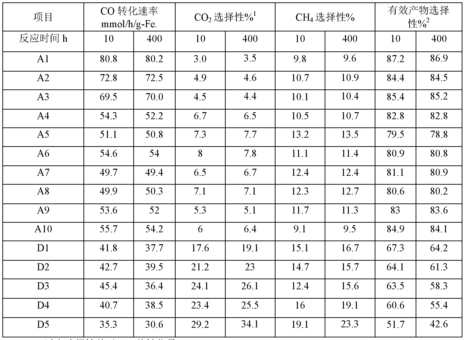
- the change process from nano-iron powder to target carbide can be clearly seen from Fig. 4; as can be seen from Fig. 5, the obtained target product 8/8' iron carbide has good crystallinity, which corresponds well to 8/. 8' All characteristic peaks of iron carbide, extremely pure, without any other impurities.
- Figure 6 clearly shows the process of changing from nano-iron powder to target carbide and the process of high-temperature steam treatment.
- Table 1 shows the specific data of phase transformation. It can be seen from Table 1 that the purity of the active phase 8/8' iron carbide in the target product prepared in Example 1 is 100%, and after long-term operation under simulated industrial conditions, Its purity is still 100%. This indicates that the method of the present invention can produce a target product active phase 8/8' iron carbide of 100% purity, while the 8/8' iron carbide obtained according to the preparation method of the present invention can stably exist at a high temperature of 250 ° C, further The 8/8' iron carbide catalyst maintains 100% purity even after simulated industrial high temperature and high pressure steam erosion.
- This example is intended to illustrate the pure phase 8/8' iron carbide catalyst of the present invention and a process for its preparation.
- the precursor 2 is placed in a tubular Fischer-Tropsch synthesis reactor, at a temperature of 510 ° C, a gas flow rate of 15000mL / h / g, a pressure of 0.2 atm of H 2 flow, reaction lh;
- This example is intended to illustrate the pure phase 8/8' iron carbide catalyst of the present invention and a process for its preparation.
- nano-needle iron ore (a-FeO(OH)) powder with an average grain diameter ranging from 19 ⁇ 7 nm (purchased from alfa reagent company, CAS No. 20344-49-4), this nanoneedle Iron ore is named precursor 3;
- the precursor 3 is placed in a tubular Fischer-Tropsch synthesis reactor, and a H 2 flow having a gas velocity of 5000 mL/h/g and a pressure of 1.3 atm is introduced at a temperature of 470 ° C for 5 hours;
- a pure phase 8/8' iron carbide catalyst was prepared according to the procedure of Example 1, except that in step (2), the pressure of the H 2 stream was 15 atm.
- the 8/8' iron carbide catalyst was obtained as A4.
- a pure phase 8/8' iron carbide catalyst was prepared according to the procedure of Example 1, except that in step (2), the gas velocity of the H 2 stream was 500 mL/h/g.
- the s/s' iron carbide catalyst was obtained as A5.
- a pure phase 8/8' iron carbide catalyst was prepared as in Example 1, except that in step (3), the pressure of the (H 2 + CO) stream was 7 atm.
- the 8/8' iron carbide catalyst was obtained as A6.
- a pure phase 8/8' iron carbide catalyst was prepared according to the procedure of Example 1, except that in step (3), the gas velocity of the (H 2 + CO) stream was 200 mL/h/g.
- the s/s' iron carbide catalyst was obtained as A7.
- a pure phase 8/8' iron carbide catalyst was prepared in accordance with the procedure of Example 1, except that in step (4), the pressure of the (H 2 + CO) stream was 0.09 atm.
- the 8/8' iron carbide catalyst was obtained as A8.
- a pure phase 8/8' iron carbide catalyst was prepared as in Example 1, except that in step (4), the gas velocity of the (H 2 +CO) stream was 200 mL/h/g.
- the s/s' iron carbide catalyst was obtained as A9.
- a pure phase 8/8' iron carbide catalyst was prepared according to the procedure of Example 1, except that in step (4), the heating rate was 5 ° C/min.
- the s/s' iron carbide catalyst was obtained as A10. Comparative example 1
- An iron carbide catalyst was prepared according to the method of Example 1, except that step (3) was not carried out. Directly process the material obtained in step (2) according to step (4). The iron carbide catalyst was obtained as D1. Comparative example 2
- An iron carbide catalyst was prepared according to the method of Example 1, except that in the step (3), the molar ratio of H 2 to CO was 1.1.
- the iron carbide catalyst was obtained as D2. Comparative example 3
- An iron carbide catalyst was prepared in accordance with the method of Example 1, except that in the step (4), the molar ratio of H 2 to CO was 0.9.
- the iron carbide catalyst was obtained as D3. Comparative example 4
- An iron carbide catalyst was prepared in the same manner as in Example 1, except that the temperature of the pretreatment in the step (3) was 200 ° C, and the temperature of the carbide in the step (4) was 290 ° C.
- the iron carbide catalyst was obtained as D4. Comparative example 5
- This comparative example is used to illustrate a method of preparing an iron carbide catalyst in the prior art (N. Lohitham et al. / Journal of Catalysis 255 (2008) 104-113).
- the raw material is 0.6mol/L.
- CO conversion % [(CO moles in feed - moles of CO in the feed) / CO moles in the feed] X 100%;
- Effective product selectivity % 100% (0 2 selectivity %-01 4 selectivity %).
- the pure phase s/s' iron carbide can be produced by the preparation method of the present invention.
- Effective product selectivity refers to product selectivity other than by-products (: 0 2 and (: 11 4 ).
- the pure phase 8/8' iron carbide catalyst prepared by the method of the present invention can be seen. It exhibits an ultra-low 00 2 selectivity under industrial conditions, and preferably, the C0 2 selectivity may be less than 5%; correspondingly, the iron carbide catalyst D5 prepared by the prior art is C0 2 under the same industrial conditions.
- the selectivity is as high as 29.2% - 34.1%.
- the pure phase 8/8' iron carbide catalyst prepared by the method of the invention has a CH 4 selectivity of less than 14% (preferably less than 11%) and an effective product selectivity of over 78% (excellent) In the case of selection, it can reach more than 84%); and the iron carbide catalyst D5 prepared by the prior art has higher CH 4 selectivity, the effective product selectivity is only 51.7%, and the CO utilization efficiency is low.
Landscapes
- Chemical & Material Sciences (AREA)
- Organic Chemistry (AREA)
- Engineering & Computer Science (AREA)
- Chemical Kinetics & Catalysis (AREA)
- Materials Engineering (AREA)
- Oil, Petroleum & Natural Gas (AREA)
- General Chemical & Material Sciences (AREA)
- Physics & Mathematics (AREA)
- Thermal Sciences (AREA)
- Catalysts (AREA)
- Organic Low-Molecular-Weight Compounds And Preparation Thereof (AREA)
- Low-Molecular Organic Synthesis Reactions Using Catalysts (AREA)
Abstract
Description


Claims
Priority Applications (6)
| Application Number | Priority Date | Filing Date | Title |
|---|---|---|---|
| RU2020133901A RU2761013C1 (ru) | 2018-04-02 | 2018-06-21 | КАТАЛИЗАТОР ИЗ ЧИСТОЙ ФАЗЫ е/е' КАРБИДА ЖЕЛЕЗА ДЛЯ РЕАКЦИИ СИНТЕЗА ФИШЕРА-ТРОПША, СПОСОБ ЕГО ПРИГОТОВЛЕНИЯ И СПОСОБ СИНТЕЗА ФИШЕРА-ТРОПША |
| EP18913406.7A EP3778014A4 (en) | 2018-04-02 | 2018-06-21 | PURE PHASE E / W IRON CARBIDE CATALYST FOR FISCHER-TROPSCH SYNTHESIS REACTION, RELATED PREPARATION PROCESS AND FISCHER-TROPSCH SYNTHESIS PROCESS |
| US17/044,688 US11471872B2 (en) | 2018-04-02 | 2018-06-21 | Pure phase ε/ε' iron carbide catalyst for Fischer-Tropsch synthesis reaction, preparation method thereof and Fischer-Tropsch synthesis process |
| GB2015587.5A GB2586728B8 (en) | 2018-04-02 | 2018-06-21 | Pure-phase ##' iron carbide catalyst for Fischer-Tropsch synthesis reaction, preparation method therefor and Fischer-Tropsch synthesis method |
| JP2020554393A JP7098747B2 (ja) | 2018-04-02 | 2018-06-21 | フィッシャー・トロプシュ合成反応用の純相ε/ε’炭化鉄触媒、その製造方法及びフィッシャー・トロプシュ合成方法 |
| ZA2020/06773A ZA202006773B (en) | 2018-04-02 | 2020-10-29 | Pure phase ε/ε’ iron carbide catalyst for fischer-tropsch synthesis reaction, preparation method therefor and fischer-tropsch synthesis process |
Applications Claiming Priority (2)
| Application Number | Priority Date | Filing Date | Title |
|---|---|---|---|
| CN201810283708.0A CN110339849B (zh) | 2018-04-02 | 2018-04-02 | 用于费托合成反应的纯相ε/ε’碳化铁催化剂及其制备方法和费托合成的方法 |
| CN201810283708.0 | 2018-04-02 |
Publications (1)
| Publication Number | Publication Date |
|---|---|
| WO2019192080A1 true WO2019192080A1 (zh) | 2019-10-10 |
Family
ID=68099914
Family Applications (1)
| Application Number | Title | Priority Date | Filing Date |
|---|---|---|---|
| PCT/CN2018/092189 Ceased WO2019192080A1 (zh) | 2018-04-02 | 2018-06-21 | 用于费托合成反应的纯相ε/ε'碳化铁催化剂及其制备方法和费托合成的方法 |
Country Status (8)
| Country | Link |
|---|---|
| US (1) | US11471872B2 (zh) |
| EP (1) | EP3778014A4 (zh) |
| JP (1) | JP7098747B2 (zh) |
| CN (1) | CN110339849B (zh) |
| GB (1) | GB2586728B8 (zh) |
| RU (1) | RU2761013C1 (zh) |
| WO (1) | WO2019192080A1 (zh) |
| ZA (1) | ZA202006773B (zh) |
Families Citing this family (2)
| Publication number | Priority date | Publication date | Assignee | Title |
|---|---|---|---|---|
| CN116920961B (zh) * | 2022-03-30 | 2025-09-19 | 国家能源投资集团有限责任公司 | 费托合成催化剂活化方法及费托合成方法 |
| CN116854091B (zh) * | 2023-06-28 | 2025-09-30 | 鞍钢股份有限公司 | 一种粒度可控的高纯碳化铁微粉制备方法 |
Citations (6)
| Publication number | Priority date | Publication date | Assignee | Title |
|---|---|---|---|---|
| WO2012135089A1 (en) * | 2011-03-26 | 2012-10-04 | Honda Motor Co., Ltd. | Fischer-tropsch catalysts containing iron or cobalt selective towards higher hydrocarbons |
| CN104399501A (zh) | 2014-11-09 | 2015-03-11 | 复旦大学 | 一种高活性铁基低温费托合成催化剂及其制备方法 |
| CN105195189A (zh) * | 2015-10-29 | 2015-12-30 | 江南大学 | 一种从合成气直接制取低碳烯烃的催化剂及其制备与应用 |
| CN105728020A (zh) * | 2016-03-03 | 2016-07-06 | 华侨大学 | 一种核壳型碳化铁催化剂制备方法 |
| KR20160104546A (ko) * | 2016-01-08 | 2016-09-05 | 한국에너지기술연구원 | 세슘이 포함된 피셔-트롭쉬 합성용 철-카바이드/탄소 복합 촉매, 이의 제조 방법, 및 상기 촉매를 이용한 액체 또는 고체 탄화수소의 제조방법 |
| CN107442147A (zh) * | 2017-08-10 | 2017-12-08 | 中南民族大学 | 一种高铁含量石墨层包裹的碳化铁催化剂及其合成方法与应用 |
Family Cites Families (25)
| Publication number | Priority date | Publication date | Assignee | Title |
|---|---|---|---|---|
| US2562806A (en) * | 1948-04-23 | 1951-07-31 | Standard Oil Dev Co | Hydrocarbon synthesis with catalyst reconditioning |
| US2535042A (en) * | 1950-01-05 | 1950-12-26 | Ernst M Cohn | Preparation of iron carbides |
| US2780537A (en) * | 1952-11-24 | 1957-02-05 | Stelling | Process of treating pulverulent iron oxides |
| US3885023A (en) * | 1973-02-15 | 1975-05-20 | Phillips Petroleum Co | Preparation of iron carbide (Fe{hd 3{b C) |
| US4842759A (en) * | 1983-04-25 | 1989-06-27 | Daikin Industries, Ltd. | Acicular process for producing particulate material |
| US5140049A (en) * | 1985-10-25 | 1992-08-18 | Exxon Research And Engineering Co. | Method for producing olefins from H2 and CO2 using an iron carbide based catalyst |
| JPH0725531B2 (ja) | 1988-09-26 | 1995-03-22 | 財団法人生産開発科学研究所 | ε’炭化鉄からなる磁性超微粒子及びその製造法 |
| US5552073A (en) * | 1988-09-26 | 1996-09-03 | Seisan Kaihatsu Kagaku Kenkyusho | Ferromagnetic fine particles of ε iron carbide and method for producing the same |
| ATE176331T1 (de) * | 1990-08-01 | 1999-02-15 | Iron Carbide Holdings Ltd | Verfahren zur kontrolle der umwandlung von eisenhaltiger reaktorzufuhr in eisenkarbid |
| US5387274A (en) * | 1993-11-15 | 1995-02-07 | C.V.G. Siderurgica Del Orinoco, C.A. | Process for the production of iron carbide |
| US5618032A (en) * | 1994-05-04 | 1997-04-08 | Midrex International B.V. Rotterdam, Zurich Branch | Shaft furnace for production of iron carbide |
| JP3294763B2 (ja) * | 1996-06-19 | 2002-06-24 | 昭二 林 | 炭化鉄の製法 |
| WO2003097236A1 (en) | 2002-05-15 | 2003-11-27 | Süd-Chemie AG | Fischer-tropsch catalyst prepared with a high purity iron precursor |
| JP4747339B2 (ja) | 2006-06-30 | 2011-08-17 | 電源開発株式会社 | フィッシャートロプシュ合成反応用鉄系触媒及びその製造方法ならびにそれを使用した炭化水素の製造方法 |
| US7915193B2 (en) * | 2007-08-30 | 2011-03-29 | Rentech, Inc. | Method for activating strengthened iron catalyst for slurry reactors |
| EA019736B1 (ru) | 2010-12-01 | 2014-05-30 | Евгений Иванович Евсюков | Ингаляционное устройство |
| EA028460B1 (ru) * | 2011-10-26 | 2017-11-30 | Рес Сша Ллс | Катализатор фишера-тропша на основе железа |
| CN103816904A (zh) * | 2012-11-16 | 2014-05-28 | 亚申科技研发中心(上海)有限公司 | 费托催化剂、其制备方法、应用以及采用该催化剂的费托合成方法 |
| KR101339902B1 (ko) | 2013-03-27 | 2013-12-10 | 한국에너지기술연구원 | 칼륨이 포함된 고온 피셔-트롭쉬 합성 반응용 철-카바이드/탄소 나노복합 촉매의 제조 방법 및 그 촉매, 철-카바이드/탄소 나노복합 촉매를 이용한 액체 탄화수소의 제조방법 및 그 액체 탄화수소 |
| EP3013472A1 (en) * | 2013-06-28 | 2016-05-04 | Dow Global Technologies LLC | Novel iron-based catalysts and treatment process therefor for use in fischer-tropsch reactions |
| KR101393413B1 (ko) | 2013-10-04 | 2014-05-12 | 한국에너지기술연구원 | 고온 피셔-트롭쉬 합성 반응용 철카바이드/탄소 나노복합 촉매의 제조 방법 및 그 촉매, 철카바이드/탄소 나노복합 촉매를 이용한 액체 탄화수소의 제조방법 및 그 액체 탄화수소 |
| CN104388501B (zh) * | 2014-10-30 | 2018-01-12 | 宁夏乙征生物工程有限公司 | 一种应用生物酶的红霉素制备方法 |
| FR3045412B1 (fr) * | 2015-12-18 | 2018-01-12 | Institut National Des Sciences Appliquees De Toulouse | Nanoparticules de carbure de fer, procede pour leur preparation et leur utilisation pour la production de chaleur |
| CN107413362B (zh) * | 2017-08-10 | 2020-03-20 | 中南民族大学 | 一种超高活性的费托合成工艺 |
| CN110339848B (zh) * | 2018-04-02 | 2020-10-13 | 国家能源投资集团有限责任公司 | 用于费托合成反应的负载型ε/ε’碳化铁催化剂及其制备方法和费托合成反应的方法 |
-
2018
- 2018-04-02 CN CN201810283708.0A patent/CN110339849B/zh active Active
- 2018-06-21 RU RU2020133901A patent/RU2761013C1/ru active
- 2018-06-21 US US17/044,688 patent/US11471872B2/en active Active
- 2018-06-21 JP JP2020554393A patent/JP7098747B2/ja active Active
- 2018-06-21 GB GB2015587.5A patent/GB2586728B8/en active Active
- 2018-06-21 WO PCT/CN2018/092189 patent/WO2019192080A1/zh not_active Ceased
- 2018-06-21 EP EP18913406.7A patent/EP3778014A4/en active Pending
-
2020
- 2020-10-29 ZA ZA2020/06773A patent/ZA202006773B/en unknown
Patent Citations (6)
| Publication number | Priority date | Publication date | Assignee | Title |
|---|---|---|---|---|
| WO2012135089A1 (en) * | 2011-03-26 | 2012-10-04 | Honda Motor Co., Ltd. | Fischer-tropsch catalysts containing iron or cobalt selective towards higher hydrocarbons |
| CN104399501A (zh) | 2014-11-09 | 2015-03-11 | 复旦大学 | 一种高活性铁基低温费托合成催化剂及其制备方法 |
| CN105195189A (zh) * | 2015-10-29 | 2015-12-30 | 江南大学 | 一种从合成气直接制取低碳烯烃的催化剂及其制备与应用 |
| KR20160104546A (ko) * | 2016-01-08 | 2016-09-05 | 한국에너지기술연구원 | 세슘이 포함된 피셔-트롭쉬 합성용 철-카바이드/탄소 복합 촉매, 이의 제조 방법, 및 상기 촉매를 이용한 액체 또는 고체 탄화수소의 제조방법 |
| CN105728020A (zh) * | 2016-03-03 | 2016-07-06 | 华侨大学 | 一种核壳型碳化铁催化剂制备方法 |
| CN107442147A (zh) * | 2017-08-10 | 2017-12-08 | 中南民族大学 | 一种高铁含量石墨层包裹的碳化铁催化剂及其合成方法与应用 |
Non-Patent Citations (5)
| Title |
|---|
| "Metal organic framework-mediated synthesis of highly active and stable Fischer-Tropsch catalysts", NATURE COMMUNICATION, 2015 |
| "Stability and reactivity of ε-x-Θ iron carbide catalyst phases in Fischer-Tropsch synthesis: Controlling c", JOURNAL OF THE AMERICAN CHEMICAL SOCIETY (JACS), 2010 |
| CHEMICAL ABSTRACTS, Columbus, Ohio, US; abstract no. 20344-49-4 |
| N. LOHITHARN ET AL., JOURNAL OF CATALYSIS, vol. 255, 2008, pages 104 - 113 |
| See also references of EP3778014A4 |
Also Published As
| Publication number | Publication date |
|---|---|
| GB2586728B (en) | 2022-06-29 |
| EP3778014A1 (en) | 2021-02-17 |
| US11471872B2 (en) | 2022-10-18 |
| US20210039081A1 (en) | 2021-02-11 |
| GB2586728A (en) | 2021-03-03 |
| JP2021528225A (ja) | 2021-10-21 |
| CN110339849B (zh) | 2020-10-13 |
| CN110339849A (zh) | 2019-10-18 |
| RU2761013C1 (ru) | 2021-12-02 |
| GB2586728B8 (en) | 2023-12-06 |
| EP3778014A4 (en) | 2021-12-22 |
| GB202015587D0 (en) | 2020-11-18 |
| JP7098747B2 (ja) | 2022-07-11 |
| GB2586728A8 (en) | 2023-12-06 |
| ZA202006773B (en) | 2022-01-26 |
Similar Documents
| Publication | Publication Date | Title |
|---|---|---|
| Gili et al. | Surface carbon as a reactive intermediate in dry reforming of methane to syngas on a 5% Ni/MnO catalyst | |
| WO2019192079A1 (zh) | 用于费托合成反应的负载型ε/ε'碳化铁催化剂及其制备方法和费托合成的方法 | |
| WO2019192080A1 (zh) | 用于费托合成反应的纯相ε/ε'碳化铁催化剂及其制备方法和费托合成的方法 | |
| CN112569985B (zh) | 含χ碳化铁组合物及其制备方法、催化剂和应用以及费托合成的方法 | |
| CN112569980B (zh) | 含沉淀型ε/ε’碳化铁和χ碳化铁的组合物及制备方法、催化剂和应用及费托合成的方法 | |
| CN112569988B (zh) | 含沉淀型ε/ε’碳化铁和θ碳化铁的组合物及制备方法、催化剂和应用及费托合成的方法 | |
| CN112569989B (zh) | 含χ碳化铁和θ碳化铁的组合物及制备方法、催化剂和应用及费托合成的方法 | |
| CN112569986B (zh) | 含θ碳化铁组合物及其制备方法、催化剂和应用以及费托合成的方法 | |
| CN112569981A (zh) | 含沉淀型θ碳化铁组合物及其制备方法、催化剂和应用以及费托合成的方法 | |
| CN112569987B (zh) | 含ε/ε’碳化铁组合物及其制备方法、催化剂和应用以及费托合成的方法 | |
| CN115069279A (zh) | 含θ碳化铁催化剂及其制备方法和应用以及费托合成的方法 | |
| CN112569994B (zh) | 含多物相碳化铁的组合物及制备方法、催化剂和应用及费托合成的方法 | |
| CN112569977B (zh) | 含沉淀型χ碳化铁和θ碳化铁的组合物及制备方法、催化剂和应用及费托合成的方法 | |
| CN112569982B (zh) | 含沉淀型ε/ε’碳化铁组合物及其制备方法、催化剂和应用以及费托合成的方法 | |
| CN112569992A (zh) | 含沉淀型χ碳化铁组合物及其制备方法、催化剂和应用以及费托合成的方法 | |
| CN112569995B (zh) | 含ε/ε’碳化铁和θ碳化铁的组合物及制备方法、催化剂和应用及费托合成的方法 | |
| CN112569975B (zh) | 含沉淀型多物相碳化铁的组合物及制备方法、催化剂和应用及费托合成的方法 | |
| Sun et al. | Modulating lattice distortion of NiO/MgAl 2-x Fe x O 4 for low-temperature methane decomposition with CO 2 reduction | |
| CN112569991B (zh) | 含ε/ε’碳化铁和χ碳化铁的组合物及制备方法、催化剂和应用及费托合成的方法 | |
| CN112569983B (zh) | 含负载型χ碳化铁组合物及其制备方法、催化剂和应用以及费托合成的方法 | |
| Cao et al. | Pure hydrogen and carbon nanotube production from methane decomposition over hydrotalcite-derived NiMCrAl (M= Co, Cu, Zn) catalysts | |
| CN118253306A (zh) | CuInZnOx复合金属氧化物催化剂的制备方法及应用 |
Legal Events
| Date | Code | Title | Description |
|---|---|---|---|
| 121 | Ep: the epo has been informed by wipo that ep was designated in this application |
Ref document number: 18913406 Country of ref document: EP Kind code of ref document: A1 |
|
| WWE | Wipo information: entry into national phase |
Ref document number: 139950140003005768 Country of ref document: IR |
|
| ENP | Entry into the national phase |
Ref document number: 2020554393 Country of ref document: JP Kind code of ref document: A Ref document number: 202015587 Country of ref document: GB Kind code of ref document: A Free format text: PCT FILING DATE = 20180621 |
|
| NENP | Non-entry into the national phase |
Ref country code: DE |
|
| ENP | Entry into the national phase |
Ref document number: 2018913406 Country of ref document: EP Effective date: 20201102 |