WO2019193714A1 - 空気調和機 - Google Patents
空気調和機 Download PDFInfo
- Publication number
- WO2019193714A1 WO2019193714A1 PCT/JP2018/014599 JP2018014599W WO2019193714A1 WO 2019193714 A1 WO2019193714 A1 WO 2019193714A1 JP 2018014599 W JP2018014599 W JP 2018014599W WO 2019193714 A1 WO2019193714 A1 WO 2019193714A1
- Authority
- WO
- WIPO (PCT)
- Prior art keywords
- temperature
- heat exchange
- indoor
- exchange unit
- unit
- Prior art date
- Legal status (The legal status is an assumption and is not a legal conclusion. Google has not performed a legal analysis and makes no representation as to the accuracy of the status listed.)
- Ceased
Links
Images

Classifications
-
- F—MECHANICAL ENGINEERING; LIGHTING; HEATING; WEAPONS; BLASTING
- F24—HEATING; RANGES; VENTILATING
- F24F—AIR-CONDITIONING; AIR-HUMIDIFICATION; VENTILATION; USE OF AIR CURRENTS FOR SCREENING
- F24F11/00—Control or safety arrangements
- F24F11/30—Control or safety arrangements for purposes related to the operation of the system, e.g. for safety or monitoring
- F24F11/32—Responding to malfunctions or emergencies
-
- G—PHYSICS
- G05—CONTROLLING; REGULATING
- G05B—CONTROL OR REGULATING SYSTEMS IN GENERAL; FUNCTIONAL ELEMENTS OF SUCH SYSTEMS; MONITORING OR TESTING ARRANGEMENTS FOR SUCH SYSTEMS OR ELEMENTS
- G05B19/00—Program-control systems
- G05B19/02—Program-control systems electric
- G05B19/04—Program control other than numerical control, i.e. in sequence controllers or logic controllers
- G05B19/042—Program control other than numerical control, i.e. in sequence controllers or logic controllers using digital processors
-
- F—MECHANICAL ENGINEERING; LIGHTING; HEATING; WEAPONS; BLASTING
- F24—HEATING; RANGES; VENTILATING
- F24F—AIR-CONDITIONING; AIR-HUMIDIFICATION; VENTILATION; USE OF AIR CURRENTS FOR SCREENING
- F24F11/00—Control or safety arrangements
- F24F11/30—Control or safety arrangements for purposes related to the operation of the system, e.g. for safety or monitoring
- F24F11/32—Responding to malfunctions or emergencies
- F24F11/38—Failure diagnosis
-
- F—MECHANICAL ENGINEERING; LIGHTING; HEATING; WEAPONS; BLASTING
- F24—HEATING; RANGES; VENTILATING
- F24F—AIR-CONDITIONING; AIR-HUMIDIFICATION; VENTILATION; USE OF AIR CURRENTS FOR SCREENING
- F24F11/00—Control or safety arrangements
- F24F11/30—Control or safety arrangements for purposes related to the operation of the system, e.g. for safety or monitoring
- F24F11/32—Responding to malfunctions or emergencies
- F24F11/39—Monitoring filter performance
-
- F—MECHANICAL ENGINEERING; LIGHTING; HEATING; WEAPONS; BLASTING
- F24—HEATING; RANGES; VENTILATING
- F24F—AIR-CONDITIONING; AIR-HUMIDIFICATION; VENTILATION; USE OF AIR CURRENTS FOR SCREENING
- F24F11/00—Control or safety arrangements
- F24F11/62—Control or safety arrangements characterised by the type of control or by internal processing, e.g. using fuzzy logic, adaptive control or estimation of values
- F24F11/63—Electronic processing
-
- G—PHYSICS
- G05—CONTROLLING; REGULATING
- G05B—CONTROL OR REGULATING SYSTEMS IN GENERAL; FUNCTIONAL ELEMENTS OF SUCH SYSTEMS; MONITORING OR TESTING ARRANGEMENTS FOR SUCH SYSTEMS OR ELEMENTS
- G05B23/00—Testing or monitoring of control systems or parts thereof
- G05B23/02—Electric testing or monitoring
- G05B23/0205—Electric testing or monitoring by means of a monitoring system capable of detecting and responding to faults
- G05B23/0259—Electric testing or monitoring by means of a monitoring system capable of detecting and responding to faults characterized by the response to fault detection
- G05B23/0283—Predictive maintenance, e.g. involving the monitoring of a system and, based on the monitoring results, taking decisions on the maintenance schedule of the monitored system; Estimating remaining useful life [RUL]
-
- F—MECHANICAL ENGINEERING; LIGHTING; HEATING; WEAPONS; BLASTING
- F24—HEATING; RANGES; VENTILATING
- F24F—AIR-CONDITIONING; AIR-HUMIDIFICATION; VENTILATION; USE OF AIR CURRENTS FOR SCREENING
- F24F2110/00—Control inputs relating to air properties
- F24F2110/10—Temperature
-
- G—PHYSICS
- G05—CONTROLLING; REGULATING
- G05B—CONTROL OR REGULATING SYSTEMS IN GENERAL; FUNCTIONAL ELEMENTS OF SUCH SYSTEMS; MONITORING OR TESTING ARRANGEMENTS FOR SUCH SYSTEMS OR ELEMENTS
- G05B2219/00—Program-control systems
- G05B2219/20—Pc systems
- G05B2219/26—Pc applications
- G05B2219/2614—HVAC, heating, ventillation, climate control
Definitions
- the present invention relates to an air conditioner that detects dirt on a heat exchanger or an air filter.
- Air filters or heat exchangers used in air conditioners are regularly cleaned.
- various methods for determining the degree of contamination based on temperatures detected by various temperature sensors have been proposed so that cleaning is performed according to the degree of contamination of the air filter (for example, Patent Documents 1 to 3). reference).
- Patent Document 1 it is determined that the air filter is clogged when the temperature difference between the surface temperature of the condenser and the temperature of the cooling air cooled by the condenser exceeds a threshold value. Outputting an alarm is disclosed.
- Patent Document 2 when it is detected that the temperature difference between the room temperature and the refrigerant outlet temperature in the evaporator has become a predetermined value or more, it is determined that an abnormality has occurred in the air filter, and the air filter is cleaned. Is disclosed.
- Patent Document 3 air filter clogging is determined based on the accumulated operation time from the time of installation, and air filter clogging is determined based on the temperature difference between the room temperature and the temperature of the indoor heat exchanger. It is disclosed.
- JP-A 61-44239 Japanese Utility Model Publication No. 5-19835 JP 2002-61995 A
- the temperature difference is compared with a predetermined threshold value to determine contamination such as clogging.
- the temperature difference may be larger than a predetermined threshold value, and it may be erroneously detected that the air filter is dirty.
- the present invention has been made to solve the above problems, and provides an air conditioner that can accurately detect the degree of contamination of an air filter or a heat exchanger regardless of environmental changes. Objective.
- the air conditioner of the present invention includes a suction temperature detection unit that detects a temperature of air sucked into the heat exchange unit or a space temperature to be heat exchanged as a suction temperature, and air blown from the heat exchange unit or the heat
- a cooling temperature detection unit that detects the temperature of the replacement unit as a cooling temperature, a difference in temperature between the suction temperature detected by the suction temperature detection unit and the cooling temperature detected by the cooling temperature detection unit at different times
- a control device that determines contamination of the heat exchange unit based on the acquired time series of the temperature difference.
- the contamination of the heat exchange unit is judged based on the time series of the temperature difference. Since detection is performed, contamination of the heat exchange unit can be accurately detected regardless of environmental changes.
- FIG. It is the schematic which shows an example of a structure of the air conditioner which concerns on Embodiment 1.
- FIG. It is a functional block diagram which shows an example of a structure of the indoor control apparatus of FIG. It is a flowchart which shows the operation example of the air conditioner of FIG.
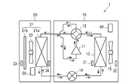
- FIG. 1 is a schematic diagram illustrating an example of a configuration of an air conditioner 1 according to the first embodiment.
- the air conditioner 1 has an outdoor unit 10 and an indoor unit 20, and a refrigerant circuit is formed by connecting the outdoor unit 10 and the indoor unit 20 via a refrigerant pipe. Yes.
- the outdoor unit 10 includes a compressor 11, a flow path switching device 12, an outdoor heat exchange unit 13, and a decompression device 14.
- the compressor 11 sucks low-temperature and low-pressure refrigerant, compresses the sucked refrigerant, and discharges high-temperature and high-pressure refrigerant.
- the compressor 11 is composed of, for example, an inverter compressor whose capacity, which is a delivery amount per unit time, is controlled by changing an operation frequency. The operating frequency of the compressor 11 is controlled by the outdoor control device 40.
- the flow path switching device 12 is a four-way valve, for example, and switches between a cooling operation and a heating operation by switching the direction in which the refrigerant flows.
- the flow path switching device 12 is switched during the cooling operation so that the discharge side of the compressor 11 and the outdoor heat exchange unit 13 are connected as shown by the solid line in FIG.
- the flow path switching device 12 is switched so that the discharge side of the compressor 11 and the indoor unit 20 are connected as shown by a broken line in FIG.
- the channel switching in the channel switching device 12 is controlled by the outdoor control device 40.
- the outdoor heat exchange unit 13 performs heat exchange between the outdoor air and the refrigerant, and includes an outdoor heat exchanger.
- the outdoor heat exchange unit 13 functions as a condenser that radiates the heat of the refrigerant to the outdoor air and condenses the refrigerant during the cooling operation.
- the outdoor heat exchange unit 13 functions as an evaporator that evaporates the refrigerant during the heating operation and cools the outdoor air with the heat of vaporization.
- Outdoor air is supplied to the outdoor heat exchange unit 13 by an outdoor fan 15.
- the decompression device 14 is composed of, for example, an electronic expansion valve or a temperature type expansion valve, and decompresses and expands the refrigerant and adjusts the flow rate of the refrigerant flowing through the refrigerant circuit.
- FIG. 1 although illustrated about the case where the decompression device 14 is provided in the outdoor unit 10 side, you may provide in the indoor unit 20 side.
- the indoor unit 20 includes an indoor heat exchange unit 21 and an indoor fan 22.
- the indoor heat exchange unit 21 includes an indoor heat exchanger 21a and an air filter 21b.
- the indoor heat exchanger 21a performs heat exchange between indoor air and water supplied by the indoor fan 22. As a result, cooling air or heating air, which is conditioned air supplied to the indoor space, is generated.
- the indoor fan 22 supplies air to the indoor heat exchanger 21a.
- the rotational speed of the indoor fan 22 is controlled by the indoor control device 50.
- the air filter 21b is provided on the air suction side of the indoor heat exchanger 21a, and removes dust and the like contained in the air sucked into the indoor heat exchanger 21a.
- the air conditioner 1 includes an outdoor suction temperature detection unit 31 and an outdoor cold temperature detection unit 32 provided on the outdoor unit 10 side, and an indoor suction temperature detection unit 33 and an indoor cold temperature detection provided on the indoor unit 20 side. Part 34.
- the outdoor suction temperature detection part 31 detects the temperature of the air sucked into the outdoor heat exchange unit 13 or the space temperature to be heat exchanged as the suction temperature.
- the outdoor cold heat temperature detection part 32 detects the temperature blown out from the outdoor heat exchange unit 13 or the temperature of the outdoor heat exchange unit 13 itself as the cold heat temperature.
- the indoor suction temperature detection unit 33 detects the indoor suction temperature Ta of the air sucked into the indoor heat exchange unit 21.
- the indoor cold temperature detection unit 34 detects the temperature of the air blown out from the indoor heat exchange unit 21 or the temperature of the indoor heat exchanger 21a itself as the cold temperature.
- the outdoor control device 40 and the indoor control device 50 are implemented by executing software on an arithmetic device such as a microcomputer, or are configured by hardware such as a circuit device that implements various functions.
- the outdoor control device 40 controls the operation of the outdoor unit 10 based on various sensor information such as the outdoor suction temperature detection unit 31 and the outdoor cold temperature detection unit 32.
- the indoor control device 50 controls the operation of the outdoor unit 10 based on various sensor information such as the indoor suction temperature detection unit 33 and the indoor cold / hot temperature detection unit 34.
- the contamination of the outdoor heat exchange unit 13 or the indoor heat exchange unit 21 is determined based on the suction temperature and the cold temperature.
- the indoor control device 50 determines the contamination of the indoor heat exchange unit 21 will be exemplified below, any one of the outdoor unit 10, the controller of the air conditioner 1, the centralized controller on the network, the server, or the like It may be performed by a plurality of arithmetic devices.
- the dirt of the indoor heat exchange unit 21 is judged is illustrated, the dirt of the outdoor heat exchange unit 13 can also be judged based on the time series of the temperature difference ⁇ T between the outdoor suction temperature and the outdoor blowing temperature. .
- FIG. 2 is a functional block diagram showing an example of the configuration of the indoor control device 50 of FIG.
- the indoor control device 50 in FIG. 2 has a function of determining the contamination of the indoor heat exchange unit 21 based on the time series of the temperature difference ⁇ T between the indoor suction temperature Ta and the indoor cooling temperature Tb.
- the indoor control device 50 includes a temperature difference calculation unit 51, a dirt determination unit 53, a storage unit 52, and an operation control unit 54.
- the temperature difference calculation unit 51 calculates and obtains a temperature difference ⁇ T between the indoor suction temperature Ta detected by the indoor suction temperature detection unit 33 and the indoor cooling temperature Tb detected by the indoor cooling temperature detection unit 34 at different times. To do.
- the temperature difference calculation unit 51 calculates the temperature difference ⁇ T and stores it in the storage unit 52 when, for example, the indoor suction temperature Ta and the indoor cooling temperature Tb are detected at a constant cycle.
- the storage unit 52 stores the acquired time and the temperature difference ⁇ T, and the temperature difference ⁇ T is stored in chronological order.
- the contamination determination unit 53 determines the contamination of the indoor heat exchange unit 21 based on the time series of the temperature difference ⁇ T stored in the storage unit 52.
- the dirt determination unit 53 determines that the indoor heat exchange unit 21 is dirty when the period in which the temperature difference ⁇ T is within the set temperature range Tbd continues longer than the setting determination period Pref.
- the dirt determination unit 53 has a function of determining the set temperature zone Tbd according to the temperature level of the indoor suction temperature Ta. For example, during the cooling operation, when the cooling load is high, the indoor suction temperature Ta and the indoor set temperature are greatly separated from each other, so that the temperature difference ⁇ T between the indoor suction temperature Ta and the indoor cooling temperature Tb also increases. On the other hand, when the indoor suction temperature Ta reaches the vicinity of the indoor set temperature, the temperature difference ⁇ T between the indoor suction temperature Ta and the indoor cooling temperature Tb becomes small. However, under any conditions, the temperature difference ⁇ T differs between the case where the indoor heat exchange unit 21 is dirty and the normal case.
- the dirt determination unit 53 stores a determination table in which the indoor suction temperature Ta is classified for each of a plurality of temperature levels, and different set temperature zones Tbd are stored for each of the plurality of temperature levels. Then, the dirt determination unit 53 selects the set temperature zone Tbd according to the temperature level of the indoor suction temperature Ta, and determines the dirt using the selected set temperature zone Tbd.
- the setting determination period Pref may be different according to the indoor suction temperature Ta instead of the set temperature zone Tbd. Both the temperature zone Tbd and the setting determination period Pref may be different according to the indoor suction temperature Ta.
- the dirt determination unit 53 determines that the indoor heat exchange unit 21 is dirty when the period in which the temperature difference ⁇ T is within the set temperature zone Tbd continues even longer than the setting determination period Pref. Alternatively, it may be determined that the indoor heat exchanging unit 21 is dirty when a period that satisfies the above-described condition appears more than a set number of times. Thereby, the accuracy of the determination of dirt can be improved. Further, the dirt determination unit 53 may learn the dirt by learning the arrival time from the start of operation until reaching the set temperature or the degree of temperature change from the steady state.
- the dirt determination unit 53 may have a function of determining whether the refrigerant is insufficient or whether the heat exchange unit 21 is dirty using the indoor cooling temperature Tb.
- the indoor cooling temperature Tb is not lowered, and the indoor suction temperature Ta (space temperature) is not lowered.
- the outdoor unit 10 performs the cooling operation, the indoor cooling temperature Tb rises when the refrigerant shortage occurs. Therefore, the dirt determination unit 53 uses the indoor cold temperature Tb to obtain a desired operation capability, but the heat exchange in the heat exchange unit 21 is hindered or a desired operation due to a lack of refrigerant. Determine if the ability is not available.
- the dirt determination unit 53 determines that the refrigerant shortage has not occurred when the indoor cooling temperature Tb is lower than the set threshold value. At this time, the contamination determination unit 53 determines the contamination of the heat exchange unit 21 based on the temporal change of the temperature difference ⁇ T as described above. On the other hand, when the indoor cooling temperature Tb is equal to or higher than the set threshold value, the dirt determination unit 53 is in a state in which a desired operation capability is not obtained even if the temperature difference ⁇ T is within the set temperature range Tbd. Judge that there is a shortage. As a result, it is possible to accurately detect whether the problem is due to contamination of the heat exchange unit 21 or the problem due to insufficient refrigerant.
- the dirt determination unit 53 considers the time change and the time change of the indoor suction temperature Ta is within a predetermined range and the period in which the temperature difference ⁇ T is within the refrigerant amount setting temperature range continues for a predetermined period. In addition, it may have a function of determining whether the refrigerant is insufficient or whether the outdoor heat exchange unit 13 is dirty. Further, the dirt determination unit 53 acquires the outdoor suction temperature or weather information, determines whether the outside air temperature is an abnormal temperature larger than the threshold value, and the temperature difference ⁇ T is gradually reduced instead of the abnormal temperature. When the time changes, it may be determined that the refrigerant is insufficient.
- the operation control unit 54 determines the degree of contamination based on the acquired time series of the temperature difference ⁇ T, and the period until the operation is abnormally stopped based on the degree of contamination is maximized. As such, it may have a function of controlling the driving ability. Then, the frequency of maintenance can be suppressed and the burden on maintenance can be reduced.
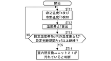
- FIG. 3 is a flowchart showing an operation example of the air conditioner according to the present invention, and an operation example of the air conditioner 1 will be described with reference to FIGS. 1 to 3. Note that FIG. 3 refers to the case of cooling operation.
- the high-temperature and high-pressure refrigerant discharged from the compressor 11 flows into the outdoor heat exchange unit 13 through the flow path switching device 12 and condenses.
- the refrigerant flowing into the indoor heat exchange unit 21 absorbs heat from the indoor air supplied via the air filter 21b by the indoor fan 22 and evaporates. On the other hand, the indoor air is cooled by the indoor heat exchange unit 21 and blown into the indoor space as conditioned air. The refrigerant flowing out from the indoor heat exchange unit 21 flows into the outdoor unit 10 and is compressed again by the compressor 11.
- the indoor control device 50 sequentially determines the contamination of the indoor heat exchange unit 21.
- the indoor suction temperature detection unit 33 detects the indoor suction temperature Ta, and the indoor cooling temperature detection unit 34 detects the indoor cooling temperature Tb (step ST11). Thereafter, in the temperature difference calculation unit 51 of the indoor control device 50, the temperature difference ⁇ T is acquired at different times and stored in the storage unit 52 (step ST12). Then, in the dirt determination unit 53, a set temperature zone Tbd for determining the dirt is determined based on the indoor suction temperature Ta. When the period during which the temperature difference ⁇ T is within the set temperature zone Tbd continues for the determined setting determination period Pref (YES in step ST13), the dirt determination unit 53 determines that the indoor heat exchange unit 21 is dirty. (Step ST14).
- step ST13 if the temperature difference ⁇ T is not within the range of the set temperature zone Tbd, or if the period is shorter than the set determination period Pref (NO in step ST13), it is caused by a temporary environmental change, and indoor heat exchange It is determined that the unit 21 is not dirty, and the determination of contamination is continued (steps ST11 to ST13).
- the contamination of the indoor heat exchange unit 21 can be accurately detected by determining the contamination of the indoor heat exchange unit 21 based on the time series of the temperature difference ⁇ T. That is, when the contamination is determined based on one preset threshold as in the prior art, even if the air filter 21b is not contaminated, the suction temperature is increased only by high environmental load, and the temperature difference ⁇ T is large. Become. Therefore, when the temperature difference ⁇ T between the two points is compared with the set threshold value to determine the contamination of the air filter 21b, erroneous detection due to environmental conditions may occur, and the detection of the contamination cannot be performed accurately.
- the indoor control device 50 determines the set temperature zone Tbd according to the indoor suction temperature Ta, and the period during which the temperature difference ⁇ T is within the set temperature zone Tbd continues longer than the determined set judgment period Pref. In this case, it is determined that the indoor heat exchange unit 21 is dirty. Thereby, since it is possible to determine the contamination using the optimum set temperature zone Tbd according to the environmental load, it is possible to determine the contamination with higher accuracy.
- the indoor control device 50 when the temperature difference ⁇ T is within the set temperature zone Tbd and continues for longer than the set determination period Pref, the indoor heat exchange unit 21 is dirty when the set number of times appears. Judge. Thereby, since it turns out that the dirt of the indoor heat exchange unit 21 has not improved even if time passes, it is possible to determine the dirt with higher accuracy.
- the indoor control device 50 determines that the indoor heat exchange unit 21 is dirty, the indoor control device 50 determines the degree of contamination based on the acquired time series of the temperature difference ⁇ T, and the period until the operation abnormally stops based on the degree of contamination. It has a function of controlling the driving ability so as to be the longest. Thereby, the frequency of maintenance can be suppressed and the burden on maintenance can be reduced.
- the indoor control device 50 determines the contamination based on the time series of the temperature difference ⁇ T.
- the indoor control device 50 may determine the contamination based on the temporal change in the cooling temperature. That is, as described above, when the indoor suction temperature Ta reaches the vicinity of the indoor set temperature, the temperature difference ⁇ T between the indoor suction temperature Ta and the indoor cooling temperature Tb becomes small. At the same time, when the indoor heat exchange unit 21 is dirty, the heat exchange between the indoor air and the refrigerant in the indoor heat exchange unit 21 is hindered, and the indoor cold heat temperature Tb of the indoor heat exchanger 21a decreases with time.
- the indoor control device 50 acquires the indoor suction temperature Ta detected by the indoor suction temperature detection unit 33 and the indoor cooling temperature Tb detected by the indoor cooling temperature detection unit 34 at different times, and the indoor suction temperature. And the contamination of the indoor heat exchange unit 21 is determined based on the time change of the indoor cooling temperature Tb.
- the indoor control device 50 determines the set temperature zone according to the indoor suction temperature Ta, and the period in which the time change of the indoor cooling temperature Tb is within the set temperature zone continues longer than the determined set judgment period. If so, it is determined that the heat exchange unit is dirty.
- the dirt determination unit 53 determines the set temperature zone based on the determination table.
- the indoor cooling temperature Tb (the temperature of the indoor heat exchanger 21a) is lowered according to the degree of filter contamination. Therefore, it can be determined that the filter needs to be cleaned only by the indoor cooling temperature Tb.
- the contamination of the indoor heat exchange unit 21 can be accurately detected by determining the contamination of the indoor heat exchange unit 21 based on the time series of the temperature change of the indoor cooling temperature Tb. it can.
- the indoor control device 50 determines the set temperature zone Tbd according to the indoor suction temperature Ta, and the period during which the temperature difference ⁇ T is within the set temperature zone Tbd continues longer than the determined set judgment period Pref. In this case, it is determined that the indoor heat exchange unit 21 is dirty. Thereby, since it is possible to determine the contamination using the optimum set temperature zone Tbd according to the environmental load, it is possible to determine the contamination with higher accuracy.
- the contamination determination unit 53 determines that the refrigerant is within the range of the set temperature zone Tbd as long as the indoor cooling temperature Tb is equal to or higher than the set threshold. You may have the function to judge that the shortage has arisen.
- the embodiment of the present invention is not limited to the above-described embodiment, and various modifications can be added.
- the cooling operation may be performed in an environment where the outside air temperature is below freezing point.
- a known anti-freezing protection mode is performed.
- the indoor control device 50 may determine the contamination taking into account the number of times the anti-freezing protection mode has been entered.
- the temperature difference ⁇ T does not continuously change for a certain time.
- the indoor cooling / heating temperature Tb the same applies to the indoor cooling / heating temperature Tb, but as the filter contamination progresses, the time change of the indoor cooling / heating temperature Tb increases. Since the number of anti-freezing protections is similarly reduced, the condition determination of the number of freezing protections can be changed from the room temperature condition. Furthermore, even if there is no indoor suction temperature Ta, the number of times of protection against freezing is reduced, so that the number of times of protection can be determined.
- the capacity adjustment may be performed so that the maintenance cycle becomes the longest in a state where the capacity does not become insufficient.
- a notification is made when an environment that uses a capacity band with a low COP (a capacity of a large compressor speed for a small capacity model) is always required.
- the temperature difference ⁇ T is calculated by subtracting the indoor cooling temperature Tb from the indoor suction temperature Ta in the cooling operation.
- the temperature difference ⁇ T is calculated from the indoor cooling temperature Tb. It is calculated by subtracting.
- the temperature change is calculated by subtracting the current indoor cooling temperature Tb from the past indoor cooling temperature Tb in the case of the cooling operation, but in the heating operation, it is calculated from the past cooling temperature. It is calculated by subtracting the indoor cooling temperature Tb.
Landscapes
- Engineering & Computer Science (AREA)
- Chemical & Material Sciences (AREA)
- Combustion & Propulsion (AREA)
- Mechanical Engineering (AREA)
- General Engineering & Computer Science (AREA)
- Physics & Mathematics (AREA)
- Signal Processing (AREA)
- Automation & Control Theory (AREA)
- General Physics & Mathematics (AREA)
- Fuzzy Systems (AREA)
- Mathematical Physics (AREA)
- Biomedical Technology (AREA)
- Health & Medical Sciences (AREA)
- Air Conditioning Control Device (AREA)
Abstract
Description
以下、本発明の実施の形態1に係る空気調和機について説明する。図1は、本実施の形態1に係る空気調和機1の構成の一例を示す概略図である。図1に示すように、空気調和機1は、室外機10、室内機20を有し、室外機10と室内機20とが冷媒配管を介して接続されることにより、冷媒回路が形成されている。
上記実施の形態1において、室内制御装置50は、温度差ΔTの時系列に基づいて汚れを判断しているが、冷熱温度の時間変化に基づいて汚れを判断するようにしてもよい。すなわち、上述したように、室内吸込温度Taが室内設定温度付近に達している場合、室内吸込温度Taと室内冷熱温度Tbとの温度差ΔTは小さくなる。同時に、室内熱交換ユニット21が汚れている場合、室内熱交換ユニット21における室内空気と冷媒との熱交換が阻害され、室内熱交換器21aの室内冷熱温度Tbは時間経過とともに低くなっていく。
Claims (10)
- 熱交換ユニットに吸い込まれる空気の温度、もしくは熱交換対象になる空間温度を吸込温度として検知する吸込温度検知部と、
前記熱交換ユニットから吹き出される空気もしくは前記熱交換ユニットの温度を冷熱温度として検知する冷熱温度検知部と、
前記吸込温度検知部により検知された前記吸込温度と、前記冷熱温度検知部により検知された前記冷熱温度との温度差を異なる時刻毎に取得し、取得した前記温度差の時系列に基づいて、前記熱交換ユニットの汚れを判断する制御装置と、
を備えた空気調和機。 - 前記制御装置は、前記吸込温度に応じて設定温度帯を決定し、前記温度差が設定温度帯の範囲内にある期間が、決定した設定判断期間よりも長く継続した場合、前記熱交換ユニットが汚れていると判断するものである請求項1に記載の空気調和機。
- 前記制御装置は、前記温度差が設定温度帯の範囲内であって設定判断期間よりも長く継続した期間が、設定回数以上出現した場合、前記熱交換ユニットが汚れていると判断するものである請求項1に記載の空気調和機。
- 前記制御装置は、前記温度差が設定温度帯の範囲内にある場合であっても、前記冷熱温度が設定閾値以上であるときには、冷媒不足が生じていると判断する機能を有する請求項1~3のいずれか1項に記載の空気調和機。
- 熱交換ユニットに吸い込まれる空気の温度、もしくは熱交換対象になる空間温度を吸込温度として検知する吸込温度検知部と、
前記熱交換ユニットから吹き出される空気もしくは前記熱交換ユニットの温度を冷熱温度として検知する冷熱温度検知部と、
前記吸込温度検知部により検知された前記吸込温度と、前記冷熱温度検知部により検知された前記冷熱温度とを異なる時刻毎に取得し、前記吸込温度と、前記冷熱温度の時間変化とに基づいて、前記熱交換ユニットの汚れを判断する制御装置と、
を備えた空気調和機。 - 前記制御装置は、前記吸込温度に応じて設定温度帯を決定し、前記冷熱温度の時間変化が設定温度帯の範囲内にある期間が、決定した設定判断期間よりも長く継続した場合、前記熱交換ユニットが汚れていると判断するものである請求項5に記載の空気調和機。
- 前記制御装置は、前記冷熱温度の時間変化が設定温度帯の範囲内にある場合であっても、前記冷熱温度が設定閾値以上であるときには、冷媒不足が生じていると判断する機能を有する請求項5又は6に記載の空気調和機。
- 前記制御装置は、前記熱交換ユニットが汚れていると判断した場合、運転が異常停止するまでの期間が最長になるように、運転能力を制御する機能を有する請求項1~7のいずれか1項に記載の空気調和機。
- 前記熱交換ユニットは、室内熱交換器と、前記室内熱交換器に流れる空気の埃塵を除去するエアフィルタとを有しており、室内機に設置されている請求項1~8のいずれか1項に記載の空気調和機。
- 前記熱交換ユニットは、室外熱交換器からなり、室外機に設置されたものである請求項1~9のいずれか1項に記載の空気調和機。
Priority Applications (6)
| Application Number | Priority Date | Filing Date | Title |
|---|---|---|---|
| EP18913517.1A EP3779305B1 (en) | 2018-04-05 | 2018-04-05 | Air conditioner |
| JP2020512184A JP6952882B2 (ja) | 2018-04-05 | 2018-04-05 | 空気調和機 |
| EP21172455.4A EP3896353B1 (en) | 2018-04-05 | 2018-04-05 | Air-conditioning apparatus |
| PCT/JP2018/014599 WO2019193714A1 (ja) | 2018-04-05 | 2018-04-05 | 空気調和機 |
| EP21172500.7A EP3896354B1 (en) | 2018-04-05 | 2018-04-05 | Air-conditioning apparatus |
| US16/970,141 US11204184B2 (en) | 2018-04-05 | 2018-04-05 | Air-conditioning apparatus with dirt detection |
Applications Claiming Priority (1)
| Application Number | Priority Date | Filing Date | Title |
|---|---|---|---|
| PCT/JP2018/014599 WO2019193714A1 (ja) | 2018-04-05 | 2018-04-05 | 空気調和機 |
Publications (1)
| Publication Number | Publication Date |
|---|---|
| WO2019193714A1 true WO2019193714A1 (ja) | 2019-10-10 |
Family
ID=68100372
Family Applications (1)
| Application Number | Title | Priority Date | Filing Date |
|---|---|---|---|
| PCT/JP2018/014599 Ceased WO2019193714A1 (ja) | 2018-04-05 | 2018-04-05 | 空気調和機 |
Country Status (4)
| Country | Link |
|---|---|
| US (1) | US11204184B2 (ja) |
| EP (3) | EP3896353B1 (ja) |
| JP (1) | JP6952882B2 (ja) |
| WO (1) | WO2019193714A1 (ja) |
Cited By (5)
| Publication number | Priority date | Publication date | Assignee | Title |
|---|---|---|---|---|
| CN112378041A (zh) * | 2020-11-12 | 2021-02-19 | 海信(山东)空调有限公司 | 空调器控制方法及空调器 |
| CN112856729A (zh) * | 2021-01-21 | 2021-05-28 | 格力电器(武汉)有限公司 | 空调室内蒸发器脏堵检测方法、空调及计算机可读存储介质 |
| CN114659159A (zh) * | 2022-03-28 | 2022-06-24 | 青岛海尔空调器有限总公司 | 空调内机是否脏堵的判断方法及其空调器 |
| JP2022127893A (ja) * | 2021-02-22 | 2022-09-01 | パナソニックIpマネジメント株式会社 | 全館空調システム、及び、その制御方法 |
| CN121632902A (zh) * | 2026-02-04 | 2026-03-10 | 绿能慧充数字技术有限公司 | 一种充电桩过滤网脏堵检测方法、电子设备及存储介质 |
Families Citing this family (3)
| Publication number | Priority date | Publication date | Assignee | Title |
|---|---|---|---|---|
| JP6944962B2 (ja) * | 2019-02-27 | 2021-10-06 | ダイキン工業株式会社 | 汚れ情報推定システム |
| WO2024164007A1 (en) * | 2023-02-03 | 2024-08-08 | Schneider Electric USA, Inc. | Hvac&r performance degradation monitor and relation builder |
| CN117212969B (zh) * | 2023-08-11 | 2025-11-18 | 青岛海尔空调器有限总公司 | 用于空调自清洁的确认方法、装置及智能空调 |
Citations (6)
| Publication number | Priority date | Publication date | Assignee | Title |
|---|---|---|---|---|
| JPS6144239A (ja) | 1984-08-08 | 1986-03-03 | Nippon Soken Inc | 空気吸入フイルタの目詰り検出装置 |
| JPH0519835U (ja) | 1991-08-20 | 1993-03-12 | 東芝機器株式会社 | 空気調和機 |
| JPH0960951A (ja) * | 1995-08-25 | 1997-03-04 | Hitachi Ltd | 空気調和装置 |
| JP2002061995A (ja) | 2000-08-16 | 2002-02-28 | Fujitsu General Ltd | 空気調和機の制御方法およびその装置 |
| JP2005345046A (ja) * | 2004-06-07 | 2005-12-15 | Hitachi Ltd | 熱源機器の劣化診断システム |
| WO2016174734A1 (ja) * | 2015-04-28 | 2016-11-03 | 三菱電機株式会社 | 空気調和装置監視装置および方法 |
Family Cites Families (16)
| Publication number | Priority date | Publication date | Assignee | Title |
|---|---|---|---|---|
| US7797062B2 (en) * | 2001-08-10 | 2010-09-14 | Rockwell Automation Technologies, Inc. | System and method for dynamic multi-objective optimization of machine selection, integration and utilization |
| US6871160B2 (en) * | 2001-09-08 | 2005-03-22 | Scientific Monitoring Inc. | Intelligent condition-based engine/equipment management system |
| EP1565720B1 (en) * | 2002-10-15 | 2015-11-18 | Danfoss A/S | A method for detecting an abnormality of a heat exchanger |
| TWI259890B (en) * | 2003-09-16 | 2006-08-11 | Lg Electronics Inc | Integral type air conditioner |
| US8045302B2 (en) * | 2008-02-20 | 2011-10-25 | Emerson Climate Technologies, Inc. | Compressor protection and grid fault detection device |
| JP4975052B2 (ja) * | 2009-03-30 | 2012-07-11 | 三菱電機株式会社 | 冷凍サイクル装置 |
| EP4109005B1 (en) * | 2012-07-03 | 2025-08-13 | Samsung Electronics Co., Ltd. | Air conditioner |
| US20150067153A1 (en) * | 2013-08-28 | 2015-03-05 | Kentucky State University | Remote monitoring of data facility in real-time using wireless sensor network |
| GB201320977D0 (en) * | 2013-11-28 | 2014-01-15 | Elstat Electronics Ltd | Heat exchanger fault diagnostic |
| US10078105B2 (en) * | 2015-09-23 | 2018-09-18 | Abb Schweiz Ag | Electrical system with arc fault detection |
| US10109994B2 (en) * | 2016-03-24 | 2018-10-23 | Littelfuse, Inc. | Multiple current sensor system |
| CN106091246B (zh) * | 2016-06-14 | 2018-09-25 | 顺德职业技术学院 | 空调器远程控制运行故障判断方法 |
| CN108073681A (zh) * | 2016-11-16 | 2018-05-25 | 发那科株式会社 | 检索装置、检索方法以及检索程序 |
| WO2018125172A1 (en) * | 2016-12-29 | 2018-07-05 | Ecoer Inc. | A method for detecting clog in ac system heat exchange or air filter |
| US10618380B2 (en) * | 2017-08-01 | 2020-04-14 | Ford Global Technologies, Llc | Method and system for coolant temperature sensor diagnostics |
| US20190154754A1 (en) * | 2017-11-17 | 2019-05-23 | Pratt & Whitney Canada Corp. | In-range sensor fault detection |
-
2018
- 2018-04-05 EP EP21172455.4A patent/EP3896353B1/en active Active
- 2018-04-05 WO PCT/JP2018/014599 patent/WO2019193714A1/ja not_active Ceased
- 2018-04-05 EP EP18913517.1A patent/EP3779305B1/en active Active
- 2018-04-05 JP JP2020512184A patent/JP6952882B2/ja active Active
- 2018-04-05 EP EP21172500.7A patent/EP3896354B1/en active Active
- 2018-04-05 US US16/970,141 patent/US11204184B2/en active Active
Patent Citations (6)
| Publication number | Priority date | Publication date | Assignee | Title |
|---|---|---|---|---|
| JPS6144239A (ja) | 1984-08-08 | 1986-03-03 | Nippon Soken Inc | 空気吸入フイルタの目詰り検出装置 |
| JPH0519835U (ja) | 1991-08-20 | 1993-03-12 | 東芝機器株式会社 | 空気調和機 |
| JPH0960951A (ja) * | 1995-08-25 | 1997-03-04 | Hitachi Ltd | 空気調和装置 |
| JP2002061995A (ja) | 2000-08-16 | 2002-02-28 | Fujitsu General Ltd | 空気調和機の制御方法およびその装置 |
| JP2005345046A (ja) * | 2004-06-07 | 2005-12-15 | Hitachi Ltd | 熱源機器の劣化診断システム |
| WO2016174734A1 (ja) * | 2015-04-28 | 2016-11-03 | 三菱電機株式会社 | 空気調和装置監視装置および方法 |
Non-Patent Citations (1)
| Title |
|---|
| See also references of EP3779305A4 |
Cited By (8)
| Publication number | Priority date | Publication date | Assignee | Title |
|---|---|---|---|---|
| CN112378041A (zh) * | 2020-11-12 | 2021-02-19 | 海信(山东)空调有限公司 | 空调器控制方法及空调器 |
| CN112378041B (zh) * | 2020-11-12 | 2022-05-24 | 海信(山东)空调有限公司 | 空调器控制方法及空调器 |
| CN112856729A (zh) * | 2021-01-21 | 2021-05-28 | 格力电器(武汉)有限公司 | 空调室内蒸发器脏堵检测方法、空调及计算机可读存储介质 |
| CN112856729B (zh) * | 2021-01-21 | 2022-08-23 | 格力电器(武汉)有限公司 | 空调室内蒸发器脏堵检测方法、空调及计算机可读存储介质 |
| JP2022127893A (ja) * | 2021-02-22 | 2022-09-01 | パナソニックIpマネジメント株式会社 | 全館空調システム、及び、その制御方法 |
| JP7531110B2 (ja) | 2021-02-22 | 2024-08-09 | パナソニックIpマネジメント株式会社 | 全館空調システム、及び、その制御方法 |
| CN114659159A (zh) * | 2022-03-28 | 2022-06-24 | 青岛海尔空调器有限总公司 | 空调内机是否脏堵的判断方法及其空调器 |
| CN121632902A (zh) * | 2026-02-04 | 2026-03-10 | 绿能慧充数字技术有限公司 | 一种充电桩过滤网脏堵检测方法、电子设备及存储介质 |
Also Published As
| Publication number | Publication date |
|---|---|
| EP3779305A4 (en) | 2021-03-24 |
| EP3779305B1 (en) | 2022-07-20 |
| JP6952882B2 (ja) | 2021-10-27 |
| EP3896354A1 (en) | 2021-10-20 |
| JPWO2019193714A1 (ja) | 2021-01-07 |
| EP3896353A1 (en) | 2021-10-20 |
| US11204184B2 (en) | 2021-12-21 |
| EP3896353B1 (en) | 2022-12-14 |
| EP3896354B1 (en) | 2022-12-14 |
| US20200400325A1 (en) | 2020-12-24 |
| EP3779305A1 (en) | 2021-02-17 |
Similar Documents
| Publication | Publication Date | Title |
|---|---|---|
| JP6952882B2 (ja) | 空気調和機 | |
| US10415842B2 (en) | Outdoor unit for air conditioner, air conditioner, and method for controlling air conditioner | |
| EP3734177B1 (en) | Control method for air conditioner | |
| AU2009263631B8 (en) | Air conditioning apparatus and air conditioning apparatus refrigerant quantity determination method | |
| US20090195070A1 (en) | Electric energy control system | |
| CN101858636A (zh) | 空调装置 | |
| EP2634512B1 (en) | Air conditioner and method of controlling the same | |
| US20160290669A1 (en) | Air-conditioning apparatus | |
| JP6433598B2 (ja) | 空調システム | |
| WO2020115935A1 (ja) | 空気調和システム | |
| US20210041128A1 (en) | Controller of air conditioning system, outdoor unit, relay unit, heat source apparatus, and air conditioning system | |
| JP6932259B2 (ja) | 空気調和装置および運転状態判定方法 | |
| CN105972758B (zh) | 空调器的化霜控制方法、化霜控制装置和空调器 | |
| JP5505477B2 (ja) | 空気調和装置および空気調和装置の冷媒量判定方法 | |
| JP6492358B2 (ja) | 制御装置、空調装置及び制御方法 | |
| KR102638181B1 (ko) | 공기조화기의 제어방법 | |
| JP5424706B2 (ja) | 冷凍サイクル装置 | |
| AU2013200092B2 (en) | Air conditioning apparatus and air conditioning apparatus refrigerant quantity determination method | |
| JP3290251B2 (ja) | 空気調和機 | |
| JP5245576B2 (ja) | 空気調和装置の冷媒量判定方法および空気調和装置 | |
| JP5245575B2 (ja) | 空気調和装置の冷媒量判定方法および空気調和装置 | |
| JP2011149646A (ja) | 空気調和機 | |
| WO2021224962A1 (ja) | 空気調和装置 | |
| JP3847314B2 (ja) | 冷媒自然循環式暖房システム | |
| JP2016065699A (ja) | 冷凍サイクル装置 |
Legal Events
| Date | Code | Title | Description |
|---|---|---|---|
| 121 | Ep: the epo has been informed by wipo that ep was designated in this application |
Ref document number: 18913517 Country of ref document: EP Kind code of ref document: A1 |
|
| ENP | Entry into the national phase |
Ref document number: 2020512184 Country of ref document: JP Kind code of ref document: A |
|
| NENP | Non-entry into the national phase |
Ref country code: DE |
|
| WWE | Wipo information: entry into national phase |
Ref document number: 2018913517 Country of ref document: EP |
|
| ENP | Entry into the national phase |
Ref document number: 2018913517 Country of ref document: EP Effective date: 20201105 |