WO2019193840A1 - フロー電池 - Google Patents
フロー電池 Download PDFInfo
- Publication number
- WO2019193840A1 WO2019193840A1 PCT/JP2019/005064 JP2019005064W WO2019193840A1 WO 2019193840 A1 WO2019193840 A1 WO 2019193840A1 JP 2019005064 W JP2019005064 W JP 2019005064W WO 2019193840 A1 WO2019193840 A1 WO 2019193840A1
- Authority
- WO
- WIPO (PCT)
- Prior art keywords
- electrode
- active material
- group
- mediator
- hydrocarbon group
- Prior art date
- Legal status (The legal status is an assumption and is not a legal conclusion. Google has not performed a legal analysis and makes no representation as to the accuracy of the status listed.)
- Ceased
Links
Images




Classifications
-
- H—ELECTRICITY
- H01—ELECTRIC ELEMENTS
- H01M—PROCESSES OR MEANS, e.g. BATTERIES, FOR THE DIRECT CONVERSION OF CHEMICAL ENERGY INTO ELECTRICAL ENERGY
- H01M8/00—Fuel cells; Manufacture thereof
- H01M8/18—Regenerative fuel cells, e.g. redox flow batteries or secondary fuel cells
- H01M8/184—Regeneration by electrochemical means
- H01M8/188—Regeneration by electrochemical means by recharging of redox couples containing fluids; Redox flow type batteries
-
- H—ELECTRICITY
- H01—ELECTRIC ELEMENTS
- H01M—PROCESSES OR MEANS, e.g. BATTERIES, FOR THE DIRECT CONVERSION OF CHEMICAL ENERGY INTO ELECTRICAL ENERGY
- H01M8/00—Fuel cells; Manufacture thereof
- H01M8/22—Fuel cells in which the fuel is based on materials comprising carbon or oxygen or hydrogen and other elements; Fuel cells in which the fuel is based on materials comprising only elements other than carbon, oxygen or hydrogen
- H01M8/225—Fuel cells in which the fuel is based on materials comprising particulate active material in the form of a suspension, a dispersion, a fluidised bed or a paste
-
- H—ELECTRICITY
- H01—ELECTRIC ELEMENTS
- H01M—PROCESSES OR MEANS, e.g. BATTERIES, FOR THE DIRECT CONVERSION OF CHEMICAL ENERGY INTO ELECTRICAL ENERGY
- H01M2300/00—Electrolytes
- H01M2300/0017—Non-aqueous electrolytes
- H01M2300/0025—Organic electrolyte
-
- Y—GENERAL TAGGING OF NEW TECHNOLOGICAL DEVELOPMENTS; GENERAL TAGGING OF CROSS-SECTIONAL TECHNOLOGIES SPANNING OVER SEVERAL SECTIONS OF THE IPC; TECHNICAL SUBJECTS COVERED BY FORMER USPC CROSS-REFERENCE ART COLLECTIONS [XRACs] AND DIGESTS
- Y02—TECHNOLOGIES OR APPLICATIONS FOR MITIGATION OR ADAPTATION AGAINST CLIMATE CHANGE
- Y02E—REDUCTION OF GREENHOUSE GAS [GHG] EMISSIONS, RELATED TO ENERGY GENERATION, TRANSMISSION OR DISTRIBUTION
- Y02E60/00—Enabling technologies; Technologies with a potential or indirect contribution to GHG emissions mitigation
- Y02E60/30—Hydrogen technology
- Y02E60/50—Fuel cells
Definitions
- This disclosure relates to a flow battery.
- Patent Document 1 discloses a redox flow battery system having an energy storage containing a redox mediator.
- Patent Document 2 discloses a flow battery using a redox species.
- One aspect of the present disclosure includes a first liquid including a first electrode mediator; A first electrode; A first active material; A first circulation mechanism for circulating the first liquid between the first electrode and the first active material,
- the first electrode mediator provides a flow battery including a benzene derivative having at least one pair of alkoxy groups at the para position.
- a flow battery using a high potential positive electrode active material can be realized.
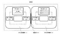
- FIG. 1 is a block diagram illustrating a schematic configuration of a flow battery according to the first embodiment.
- FIG. 2 is a schematic diagram illustrating a schematic configuration of the flow battery according to the second embodiment.
- FIG. 3 is a block diagram illustrating a schematic configuration of the flow battery according to the third embodiment.
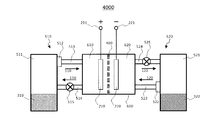
- FIG. 4 is a schematic diagram illustrating a schematic configuration of the flow battery in the fourth embodiment.
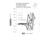
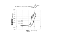
- FIG. 5 is a graph showing the measurement results of the cyclic voltammetry of the example.
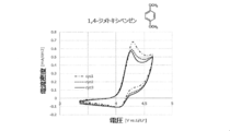
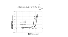
- 6A is a graph showing measurement results of cyclic voltammetry in Comparative Example 1.
- FIG. 6B is a graph showing measurement results of cyclic voltammetry in Comparative Example 2.
- FIG. 6C is a graph showing measurement results of cyclic voltammetry in Comparative Example 3.
- FIG. 6D is a graph showing measurement results of cyclic voltammetry in Comparative Example 4.
- FIG. 6E is a graph showing the measurement results of cyclic voltammetry in Compar
- the first aspect of the present disclosure is: A first liquid containing a first electrode mediator; A first electrode; A first active material; A first circulation mechanism for circulating the first liquid between the first electrode and the first active material;
- the first electrode mediator provides a flow battery including a benzene derivative having at least one pair of alkoxy groups at the para position.
- the benzene derivative has at least one atom or substituent other than a hydrogen atom at a position other than the para position having an alkoxy group.
- the benzene derivative is a benzene derivative represented by the following general formula (1).
- X 1 to X 4 are each independently hydrogen, fluorine, chlorine, bromine, cyano group, nitro group, chain saturated hydrocarbon group, chain unsaturated hydrocarbon group, cyclic saturated hydrocarbon group
- R 1 and R 2 each independently represent hydrogen, a chain saturated hydrocarbon group, a chain unsaturated hydrocarbon
- the benzene derivative is a benzene derivative represented by the following general formula (2).
- X 1 to X 4 are each independently hydrogen, fluorine, chlorine, bromine, cyano group, nitro group, chain saturated hydrocarbon group, chain unsaturated hydrocarbon group, cyclic saturated hydrocarbon group Represents a cyclic unsaturated hydrocarbon group, —COR 1 , or —N (R 2 ) 2 , and R 1 and R 2 each independently represent hydrogen, a chain saturated hydrocarbon group, a chain unsaturated hydrocarbon At least one selected from the group consisting of a group, a cyclic saturated hydrocarbon group, a cyclic unsaturated hydrocarbon group, a cyano group, a nitro group, and combinations thereof (provided that X 1 , X 2 , X 3 , and X 4 Except for compounds in which all are hydrogen at the same time.)
- the benzene derivative is a benzene derivative represented by the following general formula (3).
- X 1 and X 3 are each independently hydrogen, fluorine, chlorine, bromine, cyano group, nitro group, chain saturated hydrocarbon group, chain unsaturated hydrocarbon group, or cyclic saturated hydrocarbon group.
- the benzene derivative is a benzene derivative represented by the following general formula (4).
- X 1 and X 3 are each independently hydrogen, fluorine, chlorine, bromine, cyano group, nitro group, chain saturated hydrocarbon group, chain unsaturated hydrocarbon group, or cyclic saturated hydrocarbon group.
- the benzene derivative is 1,4-di (tert-butyl) -2,5-dimethoxybenzene, 1 , 4-dichloro-2,5-dimethoxybenzene, 1,4-difluoro-2,5-dimethoxybenzene, and 1,4-dibromo-2,5-dimethoxybenzene.
- the benzene derivative has a first redox potential and a second redox potential,
- the equilibrium potential of the first active material is higher than the first redox potential and lower than the second redox potential.
- the first liquid further includes a first electrode-side discharge mediator, Benzene derivatives have an oxidation potential, The equilibrium potential of the first active material is lower than the oxidation potential of the benzene derivative, The equilibrium potential of the first active material is higher than the equilibrium potential of the first electrode-side discharge mediator.
- the first circulation mechanism includes a first accommodating portion, The first active material and the first liquid are accommodated in the first accommodating portion, The first circulation mechanism circulates the first liquid between the first electrode and the first accommodating portion, When the first active material and the first liquid come into contact with each other in the first housing portion, at least one of an oxidation reaction and a reduction reaction between the first active material and the first electrode mediator is performed. Is called.
- the first circulation mechanism includes a first permeation suppression unit that suppresses permeation of the first active material, The first permeation suppression unit is provided in a path through which the first liquid flows out from the first storage unit to the first electrode.
- a second liquid comprising a charge mediator and a discharge mediator; A second electrode immersed in the second liquid; A second active material immersed in the second liquid; An isolation part that isolates the first electrode and the first liquid from the second electrode and the second liquid;
- the equilibrium potential of the charging mediator is lower than the equilibrium potential of the second active material,
- the equilibrium potential of the discharge mediator is higher than the equilibrium potential of the second active material.
- Lithium is dissolved in the second liquid
- the second active material is a substance having a property of occluding and releasing the lithium
- the charging mediator is reduced on the second electrode, and the charging mediator reduced on the second electrode is oxidized by the second active material and the second active material is Occludes lithium
- the second active material that occludes lithium reduces the discharge mediator
- the second active material releases the lithium
- the discharge mediator reduced by the second active material is Oxidized on the second electrode.
- the discharge mediator is reduced on the second electrode
- the charging mediator is oxidized on the second electrode
- the charge mediator and the discharge mediator are condensed aromatic compounds
- the second liquid in which the condensed aromatic compound is dissolved has a property of releasing lithium solvated electrons and dissolving the lithium as a cation.
- the charge mediator is at least one selected from the group consisting of phenanthrene, biphenyl, o-terphenyl, triphenylene, and anthracene.
- the discharge mediator is phenanthroline, 2,2′-bipyridyl, benzophenone, trans-stilbene, 4,4′-bipyridyl, 3,3′-bipyridyl, 2,4′-bipyridyl, 2,3′-bipyridyl, cis- It is at least one selected from the group consisting of stilbene, acetophenone, propiophenone, butyrophenone, valerophenone, and ethylenediamine.
- a second circulation mechanism including a second housing portion;
- the second active material and the second liquid are accommodated in the second accommodating portion,
- the second circulation mechanism circulates the second liquid between the second electrode and the second accommodating portion,
- an oxidation reaction of the charge mediator by the second active material and a reduction reaction of the discharge mediator by the second active material At least one of them is performed.
- the second circulation mechanism includes a second permeation suppression unit that suppresses permeation of the second active material,
- the second permeation suppression unit is provided in a path through which the second liquid flows from the second storage unit to the second electrode.
- the cation radical of the benzene derivative is stabilized and reversibly charged / discharged by the electron-donating conjugation effect due to the presence of an unshared electron pair of the alkoxy group bonded to the para position.
- a flow battery having a higher discharge potential can be realized.
- FIG. 1 is a block diagram illustrating a schematic configuration of a flow battery 1000 according to the first embodiment.
- the flow battery 1000 in Embodiment 1 includes a first liquid 110, a first electrode 210, a first active material 310, and a first circulation mechanism 510.
- the first liquid 110 is a liquid in which the first electrode mediator 111 is dissolved.
- the first electrode 210 is an electrode immersed in the first liquid 110.
- the first active material 310 is an active material immersed in the first liquid 110.
- the first circulation mechanism 510 is a mechanism for circulating the first liquid 110 between the first electrode 210 and the first active material 310.
- the first electrode mediator 111 includes a benzene derivative having at least one pair of alkoxy groups at the para position.
- the first electrode mediator 111 may have at least one pair of alkoxy groups at the para position and include at least one atom or substituent other than a hydrogen atom at the other position.
- a flow battery having a high discharge potential, a high energy density, and a long cycle life can be realized. That is, according to the above configuration, since the redox potential of the benzene derivative is around 4 V, as a charge mediator such as LiCoO 2 , LiNiO 2 , LiMn 2 O 4, or a discharge mediator such as LiNi 0.5 Mn 1.5 O 4 Can be used. Also, only one kind of benzene derivative can be used. Therefore, an active material having a high equilibrium potential can be used as the first active material 310, and a flow battery having a higher discharge potential can be realized. An active material having a high equilibrium potential is, for example, 3.8 to 4.5 V vs. An active material of the order of Li / Li + may be used.
- a flow battery having a configuration in which the active material itself is not circulated while using the active material can be realized.
- the 1st active material 310 a high capacity
- capacitance powder active material can be used for charging / discharging reaction, for example. Thereby, a high energy density and a high capacity can be realized.
- the benzene derivative may be a benzene derivative represented by the following general formula (1).
- X 1 to X 4 are each independently hydrogen, fluorine, chlorine, bromine, cyano group, nitro group, chain saturated hydrocarbon group, chain unsaturated hydrocarbon group, cyclic saturated hydrocarbon group, A cyclic unsaturated hydrocarbon group, —COR 1 , or —N (R 2 ) 2 , wherein R 1 and R 2 each independently represent hydrogen, a chain saturated hydrocarbon group, a chain unsaturated hydrocarbon group; And at least one selected from the group consisting of a cyclic saturated hydrocarbon group, a cyclic unsaturated hydrocarbon group, a cyano group, a nitro group, and combinations thereof.
- Y 1 and Y 2 are each independently selected from the group consisting of chain saturated hydrocarbon groups, chain unsaturated hydrocarbon groups, cyclic saturated hydrocarbon groups, cyclic unsaturated hydrocarbon groups, and combinations thereof. At least one (excluding compounds in which X 1 , X 2 , X 3 , and X 4 are all simultaneously hydrogen)
- a high potential solid positive electrode active material can be used, and a flow battery having a high discharge voltage can be realized.
- the chain saturated hydrocarbon group, the chain unsaturated hydrocarbon group, the cyclic saturated hydrocarbon group, and the cyclic unsaturated hydrocarbon group are at least one selected from the group consisting of oxygen, nitrogen, sulfur, and silicon. It may contain an element.
- R 1 and R 2 are boron, nitrogen, oxygen, fluorine, silicon, phosphorus, sulfur, chlorine, bromine, And at least one element (non-metallic element) selected from the group consisting of iodine.
- the chain saturated hydrocarbon group according to X 1 to X 4 , R 1 , R 2 , Y 1 , and Y 2 may be a chain saturated hydrocarbon group having 1 to 10 carbon atoms.
- Examples of the chain saturated hydrocarbon group having 1 to 10 carbon atoms include methyl group, ethyl group, n-propyl group, isopropyl group, n-butyl group, isobutyl group, n-pentyl group, n-hexyl group, n- Examples include heptyl group, n-octyl group, n-nonyl group, n-decyl group and the like.
- the chain unsaturated hydrocarbon group according to X 1 to X 4 , R 1 , R 2 , Y 1 , and Y 2 may be a chain unsaturated hydrocarbon group having 2 to 6 carbon atoms.
- Examples of the chain unsaturated hydrocarbon group having 2 to 6 carbon atoms include vinyl group, 1-propenyl group, 2-propenyl group, 1-methyl-1-ethenyl group, 1-butenyl group, 2-butenyl group, 3 -Butenyl group, 2-methyl-1-propenyl group, 1-ethylethenyl group, 1-methyl-1-propenyl group, 1-methyl-2-propenyl group, 1-pentenyl group, 2-pentenyl group, 3-pentenyl group 4-pentenyl group, 1-n-propylethenyl group, 1,1-dimethyl-2-propenyl group, 1-i-propylethenyl group, 1,2-dimethyl-1-propenyl group, 1-hexenyl group 2-hexenyl group, 3-hexenyl group, 4-hexenyl group, 5-hexenyl group, 1-methyl-1-pentenyl group and the like.
- the cyclic saturated hydrocarbon group according to X 1 to X 4 , R 1 , R 2 , Y 1 , and Y 2 may be a cyclic saturated hydrocarbon group having 5 to 12 carbon atoms.
- Examples of the cyclic saturated hydrocarbon group having 5 to 12 carbon atoms include a cyclopentyl group, a cyclohexyl group, a cycloheptyl group, a cyclooctyl group, a cyclodecyl group, a cycloundecyl group, and a cyclododecyl group.
- the cyclic unsaturated hydrocarbon group according to X 1 to X 4 , R 1 , R 2 , Y 1 , and Y 2 may be a cyclic unsaturated hydrocarbon group having 5 to 12 carbon atoms.
- Examples of the cyclic unsaturated hydrocarbon group having 5 to 12 carbon atoms include cyclopentenyl group, cyclohexenyl group, cyclooctenyl group, cycloundecynyl group, cyclododecynyl group, cyclohexadienyl group, cyclooctadienyl group, cyclododecadienyl
- an aliphatic cyclic unsaturated hydrocarbon group having or not having a side chain such as a cyclododecatrienyl group
- an aromatic hydrocarbon group having a side chain such as toluene and xylene.
- the cation radical of the benzene derivative is stabilized and reversibly charged and discharged by the electron-donating conjugation effect due to the presence of the lone pair of the alkoxy group bonded to the para position, and a higher discharge potential is obtained.
- a flow battery can be realized.
- X 1 to X 4 are each independently hydrogen, fluorine, chlorine, bromine, cyano group, nitro group, chain saturated hydrocarbon group, chain unsaturated hydrocarbon group, cyclic saturated hydrocarbon group, A cyclic unsaturated hydrocarbon group, —COR 1 , or —N (R 2 ) 2 , wherein R 1 and R 2 each independently represent hydrogen, a chain saturated hydrocarbon group, a chain unsaturated hydrocarbon group; , At least one selected from the group consisting of a cyclic saturated hydrocarbon group, a cyclic unsaturated hydrocarbon group, a cyano group, a nitro group, and combinations thereof (where X 1 , X 2 , X 3 , and X 4 are Except for compounds that are all hydrogen at the same time).
- the chain saturated hydrocarbon group, the chain unsaturated hydrocarbon group, and the cyclic saturated hydrocarbon group are each independently hydrogen, fluorine, chlorine, bromine, cyano group, nitro group, chain saturated hydrocarbon group, chain uns
- the benzene derivative may be a benzene derivative represented by the following general formula (3).
- X 1 and X 3 are each independently hydrogen, fluorine, chlorine, bromine, cyano group, nitro group, chain saturated hydrocarbon group, chain unsaturated hydrocarbon group, cyclic saturated hydrocarbon group
- R 1 and R 2 each independently represent hydrogen, a chain saturated hydrocarbon group, a chain unsaturated hydrocarbon At least one selected from the group consisting of a group, a cyclic saturated hydrocarbon group, a cyclic unsaturated hydrocarbon group, a cyano group, a nitro group, and combinations thereof (provided that a compound in which X 1 and X 3 are hydrogen at the same time) except).
- Y 1 and Y 2 are each independently at least one selected from the group consisting of a chain saturated hydrocarbon group, a chain unsaturated hydrocarbon group, a cyclic saturated hydrocarbon group, a cyclic unsaturated hydrocarbon group, and combinations thereof. It is.
- R 1 and R 2 are boron, nitrogen, oxygen, fluorine, silicon, phosphorus, sulfur, chlorine, It may contain at least one element (non-metallic element) selected from the group consisting of bromine and iodine.
- the chain saturated hydrocarbon group, the chain unsaturated hydrocarbon group, and the cyclic saturated hydrocarbon group related to X 1 , X 3 , R 1 , R 2 , Y 1 , and Y 2 are described in the general formula (1). It is the same as what I did.
- the benzene derivative may be a benzene derivative represented by the following general formula (4).
- X 1 and X 3 are each independently hydrogen, fluorine, chlorine, bromine, cyano group, nitro group, chain saturated hydrocarbon group, chain unsaturated hydrocarbon group, cyclic saturated hydrocarbon group Represents a cyclic unsaturated hydrocarbon group, —COR 1 , or —N (R 2 ) 2 , and R 1 and R 2 each independently represent hydrogen, a chain saturated hydrocarbon group, a chain unsaturated hydrocarbon At least one selected from the group consisting of a group, a cyclic saturated hydrocarbon group, a cyclic unsaturated hydrocarbon group, a cyano group, a nitro group, and combinations thereof (provided that a compound in which X 1 and X 3 are hydrogen at the same time) except).
- the benzene derivative is 1,4-di (tert-butyl) -2,5-dimethoxybenzene, 1,4-dichloro-2,5-dimethoxybenzene, 1,4. It may be at least one selected from the group consisting of -difluoro-2,5-dimethoxybenzene and 1,4-dibromo-2,5-dimethoxybenzene.
- Table 1 shows the measurement results of the potential of a benzene derivative that can be used as the first electrode mediator 111.
- An electrolyte solution in which a 1M electrolyte was dissolved in a solvent was prepared. LiBF 4 was used as the electrolyte. Propylene carbonate (PC) was used as the solvent. Table 1 shows combinations of the electrolyte and the solvent. By dissolving 5 mM of each benzene derivative shown in Table 1 in the electrolytic solution, an electrolytic solution corresponding to each benzene derivative shown in Table 1 was obtained. A cell for potential measurement corresponding to each benzene derivative shown in Table 1 was prepared with each electrolyte solution, counter electrode, working electrode, and reference electrode. A 1 ⁇ 1 cm Pt foil was used for the counter electrode. As the working electrode, a glassy carbon electrode ( ⁇ 6 mm) for electrochemical measurement was used.
- a silver wire (Ag / Ag + ) was used as the reference electrode.
- the charge / discharge potential of each benzene derivative shown in Table 1 was measured by cyclic voltammetry (CV) measurement using each potential measurement cell.
- Table 1 shows the potential (V vs. Li / Li + ) in which the measured charge / discharge potential was converted on the basis of lithium metal.
- the benzene derivative has an oxidation-reduction potential at 4.0 to 4.4 (V vs. Li / Li + ). Therefore, it can be used as a charge mediator for a positive electrode solid active material having an equilibrium potential lower than the first oxidation potential, which is the charge potential.
- One kind of positive electrode solid active material having an equilibrium potential between the first oxidation potential and the first reduction potential which is the charge potential can be used as a charge / discharge mediator.
- the first-stage oxidation potential first oxidation potential: E 1 ox (V vs. Li / Li + )
- the first-stage reduction potential first reduction potential: E 1 red (V vs. Li / Li + )
- E 1 red V vs. Li / Li +
- the benzene derivatives 1,4-di (tert-butyl) -2,5-dimethoxybenzene, 1,4-dichloro-2,5-dimethoxybenzene, 1,4-difluoro-2,5-dimethoxybenzene, and 1,4-dibromo-2,5-dimethoxybenzene has a first redox potential approximately 0.5 V higher than tetrathiafulvalene or a conventional positive electrode discharge mediator.
- the discharge potential of the flow battery is determined by the potential of the discharge mediator on the positive electrode side. For this reason, if it is a benzene derivative in the above-mentioned Embodiment 1 which has a discharge potential in the high potential side, the flow battery which has a higher discharge potential is realizable.
- the first electrode mediator 111 may include only one kind of benzene derivative in the first embodiment.
- the first electrode mediator 111 may include two or more kinds of benzene derivatives in the first embodiment.
- the benzene derivative in Embodiment 1 has the first oxidation potential E 1 ox and the first reduction potential E 1 red.
- the equilibrium potential (V vs. Li / Li + ) of the first active material 310 may be lower than the first oxidation potential E 1 ox and higher than the first reduction potential E 1 red.
- the benzene derivative in Embodiment 1 can function as a discharge mediator.
- the first active material 310 an active material having a potential nobler than the first reduction potential E 1 red
- the benzene derivative in Embodiment 1 can function as a discharge mediator.
- the benzene derivative in Embodiment 1 can function as a charge mediator.
- the benzene derivative in Embodiment 1 can function as a charge mediator.
- the first active material 310 may be a metal oxide represented by Li x M y O 2.
- M is at least one selected from the group consisting of Ni, Mn, and Co.
- x and y are arbitrary values.
- the metal oxide has an equilibrium potential of 3.8 to 4.4V.
- the first active material 310 may be at least one selected from the group consisting of LiFePO 4 , LiMnO 2 , LiMn 2 O 4 , and LiCoO 2 .
- the equilibrium potential of LiCoO 2 is 3.9 V vs. Li / Li + .
- the first electrode mediator 111 is charged and discharged mediator
- a mediator type positive electrode using LiCoO 2 as an active material can be constituted.
- the discharge potential of the first electrode mediator 111 is lower than the equilibrium potential of LiCoO 2, and, when closer to the equilibrium potential of LiCoO 2, the discharge potential of the flow cell is higher.
- the condition cannot be satisfied with only one type of mediator, it is necessary to use a plurality of types of mediators in order to perform charge / discharge.
- LiCoO 2 when LiCoO 2 is used as the first active material 310, at least one benzene derivative is used as the charge mediator of the first electrode mediator 111 and 3.78 V vs. 3 is used as the discharge mediator.
- the discharge potential of the flow battery can be further increased by using heteroaromatic rings and a cyclopentadienyl compound that reversibly undergo one or more redox reactions with Li / Li + .
- Benzene derivatives as charge mediators are 1,4-di (tert-butyl) -2,5-dimethoxybenzene, 1,4-dichloro-2,5-dimethoxybenzene, 1,4-difluoro-2,5-dimethoxy.
- the cyclopentadienyl compound as the discharge mediator may be 1,1′-dibromoferrocene or the like.
- the discharge potential can be increased by about 0.4 to 0.5 V as compared with the case where LiFePO 4 having a discharge potential near 3.5 V is used as the positive electrode solid active material.
- Benzene derivatives may be used as charge mediators.
- a mediator species having a redox potential lower than the equilibrium potential of the positive electrode solid active material may be used as the discharge mediator.
- the first electrode-side discharge mediator may be further dissolved in the first liquid 110.
- the first liquid 110 may further include a first electrode-side discharge mediator.
- the equilibrium potential of the first active material 310 may be lower than the oxidation potential Eox of the benzene derivative.
- the equilibrium potential of the first active material 310 may be higher than the equilibrium potential of the first electrode-side discharge mediator.
- the active material having an equilibrium potential lower than the oxidation potential Eox of the benzene derivative is used as the first active material 310, whereby the benzene derivative in Embodiment 1 can function as a charge mediator.
- the benzene derivative in Embodiment 1 can function as a charge mediator.
- the first electrode-side discharge mediator can function as a discharge mediator by using, as the first active material 310, an active material that shows a lower potential than the equilibrium potential of the first electrode-side discharge mediator.
- the first electrode-side discharge mediator may be a heteroaromatic ring such as tetrathiafulvalene or triphenylamine, and / or a cyclopentadienyl compound such as ferrocene.
- Benzene derivatives may be used as discharge mediators.
- a mediator species having a redox potential nobler than the equilibrium potential of the positive electrode solid active material may be used as the charge mediator.
- a solid active material may be used as the first active material 310.
- the solid active material may be, for example, a powdered active material.
- a pellet-shaped active material may be used as the first active material 310.
- the pellet-shaped active material may be, for example, an active material obtained by pelletizing powder.
- the binder may be, for example, polyvinylidene fluoride, polypropylene, polyethylene, polyimide, and the like.
- the first active material 310 may be a material that is insoluble in the first liquid 110. Accordingly, it is possible to realize a flow battery having a configuration in which the first electrode mediator 111 is circulated together with the first liquid 110 but the first active material 310 is not circulated.
- the first liquid 110 includes propylene carbonate (PC), ethylene carbonate (EC), ⁇ -butyrolactone dimethyl carbonate (DMC), ethyl methyl carbonate (EMC), and fluoroethylene carbonate (FEC). And at least one selected from the group consisting of diethyl carbonate (DEC).
- the first liquid 110 may be an ether solvent.
- the ether solvent include tetrahydrofuran (THF), 2-methyltetrahydrofuran (2MeTHF), dimethoxyethane (DME), 1,3-dioxane (1,3DO), 4-methyl-1,3-dioxane (4Me1,3DO). It may be.
- the first liquid 110 may be an electrolytic solution containing an electrolyte using the material of the first liquid 110 described above as a solvent.
- the electrolyte (salt) may be at least one selected from the group consisting of LiBF 4 , LiPF 6 , and LiN (CF 3 SO 2 ) 2 .
- the solvent may have a high dielectric constant, a low reactivity with Li ions, and a potential window up to about 4V.
- the first electrode 210 may be a positive electrode and the second electrode 220 may be a negative electrode.
- the first electrode 210 can be a negative electrode.
- the first electrode 210 may be a negative electrode
- the second electrode 220 may be a positive electrode
- the first electrode 110 is oxidized or reduced by the first electrode 210 when the first liquid 110 comes into contact with the first electrode 210.
- the first electrode 210 may be an electrode having a surface that acts as a reaction field of the first electrode mediator 111.
- a material that is stable with respect to the first liquid 110 can be used as the first electrode 210.
- the material that is stable with respect to the first liquid 110 may be, for example, a material that is insoluble in the first liquid 110.
- a material that is stable against an electrochemical reaction that is an electrode reaction can be used as the first electrode 210.
- a metal, carbon, or the like can be used as the first electrode 210.
- the metal may be, for example, stainless steel, iron, copper, nickel or the like.
- the first electrode 210 may have a structure with an increased surface area. What has the structure which increased the surface area may be a mesh, a nonwoven fabric, a surface roughening process board, a sintered porous body, etc., for example. According to this, the specific surface area of the first electrode 210 is increased. Thereby, the oxidation reaction or the reduction reaction of the first electrode mediator 111 can be further facilitated.
- the second electrode 220 may be configured to include a current collector and an active material provided on the current collector. Thereby, for example, a high-capacity active material can be used.
- a high-capacity active material can be used as the active material of the second electrode 220.
- a compound having a property of reversibly occluding and releasing lithium ions can be used as the active material of the second electrode 220.
- the second electrode 220 may be lithium metal.
- lithium metal When lithium metal is used as the second electrode 220, it is easy to control dissolution and precipitation as a metal positive electrode, and a high capacity can be realized.
- the flow battery 1000 according to the first embodiment may further include the isolation unit 400.
- the isolation unit 400 isolates the first electrode 210 and the first liquid 110 from the second electrode 220.
- the isolation part 400 may be a microporous film and / or a porous body used in a known secondary battery.
- the isolation part 400 may be a porous film such as glass paper in which glass fibers are woven into a nonwoven fabric.
- the isolation part 400 may be a diaphragm having ion conductivity such as lithium ion conductivity.
- the isolation part 400 may be an ion exchange resin film or a solid electrolyte film.
- the ion exchange resin membrane may be, for example, a cation exchange membrane or an anion exchange membrane.
- the first circulation mechanism 510 is a mechanism for circulating the first liquid 110 between the first electrode 210 and the first active material 310.
- the first electrode mediator 111 together with the first liquid 110 can be circulated between the first electrode 210 and the first active material 310. Thereby, the oxidation reaction and reduction reaction between each material can be performed more efficiently.
- the first circulation mechanism 510 may be a mechanism including, for example, a pipe, a tank, a pump, a valve, and the like.
- first circulation mechanism 510 there is a configuration of a second embodiment described later.
- the first electrode 210 is a positive electrode and is carbon black.
- the first liquid 110 is an ether solution in which the first electrode mediator 111 is dissolved.
- the first electrode mediator 111 is the above-described benzene derivative of Embodiment 1 (hereinafter referred to as dialkoxybenzene: DAB).
- the first active material 310 is lithium cobalt oxide (LiCoO 2 ).
- the second electrode 220 is a negative electrode and is lithium metal.
- Charging is performed by applying a voltage between the first electrode 210 and the second electrode 220.
- reaction on the negative electrode side By applying voltage, electrons are supplied from the outside of the flow battery to the second electrode 220 that is the negative electrode. Thereby, a reduction reaction occurs in the second electrode 220 which is a negative electrode. That is, the negative electrode is in a charged state.
- the first electrode mediator 111 undergoes an oxidation reaction at the first electrode 210 that is the positive electrode. That is, the first electrode mediator 111 is oxidized on the surface of the first electrode 210. Thereby, electrons are emitted from the first electrode 210 to the outside of the flow battery.
- the first circulation mechanism 510 moves the first electrode mediator 111 oxidized by the first electrode 210 to the place where the first active material 310 is provided. That is, the first circulation mechanism 510 supplies the first electrode mediator 111 oxidized by the first electrode 210 to the place where the first active material 310 is provided.
- the first electrode mediator 111 oxidized on the first electrode 210 is reduced by the first active material 310. That is, the first active material 310 is oxidized by the first electrode mediator 111. As a result, the first active material 310 releases lithium ions.
- the first circulation mechanism 510 moves the first electrode mediator 111 reduced by the first active material 310 to the place where the first electrode 210 is provided. In other words, the first circulation mechanism 510 supplies the first electrode mediator 111 reduced by the first active material 310 to the place where the first electrode 210 is provided.
- the first electrode mediator 111 is oxidized on the surface of the first electrode 210.
- a part of lithium ions (Li + ) generated from the first active material 310 can move to the second electrode 220 side through the isolation part 400.
- the first electrode mediator 111 has not changed when viewed in the total reaction including circulation.
- the 1st active material 310 located in the place away from the 1st electrode 210 will be in a charging state.
- DAB + serves as a charging mediator as the first electrode-side charging mediator.
- DAB + exists in the first liquid 110, and the first active material 310 becomes CoO 2 .
- the charging potential is determined by the oxidation potential to DAB + .
- the above charging reaction can proceed until either the first active material 310 is fully charged or the second electrode 220 is fully charged.
- the first active material 310 and the second electrode 220 are in a charged state.
- reaction on the negative electrode side In the second electrode 220 that is the negative electrode, an oxidation reaction occurs. That is, the negative electrode is in a discharged state.
- reaction on the positive electrode side By discharging the battery, electrons are supplied from the outside of the flow battery to the first electrode 210 which is a positive electrode.
- the first electrode mediator 111 is reduced on the surface of the first electrode 210.
- the first circulation mechanism 510 moves the first electrode mediator 111 reduced by the first electrode 210 to the place where the first active material 310 is provided. In other words, the first circulation mechanism 510 supplies the first electrode mediator 111 reduced by the first electrode 210 to the place where the first active material 310 is provided.
- the first electrode mediator 111 reduced on the first electrode 210 is oxidized by the first active material 310. That is, the first active material 310 is reduced by the first electrode mediator 111. Accordingly, the first active material 310 occludes lithium.
- the first circulation mechanism 510 moves the first electrode mediator 111 oxidized by the first active material 310 to the place where the first electrode 210 is provided. That is, the first circulation mechanism 510 supplies the first electrode mediator 111 oxidized by the first active material 310 to the place where the first electrode 210 is provided.
- the first electrode mediator 111 is reduced on the surface of the first electrode 210.
- a part of the lithium ions (Li + ) can be supplied from the second electrode 220 side through the isolation part 400.
- the first electrode mediator 111 has not changed when viewed in the total reaction including circulation.
- the 1st active material 310 located in the place away from the 1st electrode 210 will be in a discharge state.
- DAB serves as a discharge mediator as the first electrode side discharge mediator.
- DAB is present in the first liquid 110, and the first active material 310 becomes LiCoO 2 .
- the discharge potential is determined by the reduction potential to DAB.
- the above discharge reaction can proceed until either the first active material 310 is in a fully discharged state or the second electrode 220 is in a fully discharged state.
- Embodiment 2 Hereinafter, Embodiment 2 will be described.
- the description which overlaps with the above-mentioned Embodiment 1 is abbreviate
- FIG. 2 is a schematic diagram exemplarily showing a schematic configuration of the flow battery 2000 according to the second embodiment.
- the flow battery 2000 in Embodiment 2 has the following configuration in addition to the configuration of the flow battery 1000 in Embodiment 1 described above.
- the first circulation mechanism 510 includes a first accommodating portion 511.
- the first active material 310 and the first liquid 110 are accommodated in the first accommodating portion 511.
- the first circulation mechanism 510 circulates the first liquid 110 between the first electrode 210 and the first storage unit 511.
- the first liquid 110 and the first active material 310 can be brought into contact with each other in the first housing portion 511. Thereby, for example, the contact area between the first liquid 110 and the first active material 310 can be further increased. Further, the contact time between the first liquid 110 and the first active material 310 can be made longer. For this reason, the oxidation reaction and the reduction reaction of the first electrode mediator 111 by the first active material 310 can be performed more efficiently.
- the first storage unit 511 may be a tank, for example.
- the first storage unit 511 may store, for example, the first liquid 110 in which the first electrode mediator 111 is dissolved in the gap between the filled first active material 310.
- the first storage unit 511 may store, for example, the first liquid 110 in which the first electrode mediator 111 is dissolved in the gap between the filled first active material 310.
- the flow battery 2000 in the second embodiment may further include an electrochemical reaction unit 600, a positive electrode terminal 211, and a negative electrode terminal 221.
- the electrochemical reaction unit 600 is separated into the positive electrode chamber 610 and the negative electrode chamber 620 by the isolation unit 400.
- an electrode serving as a positive electrode is disposed in the positive electrode chamber 610.
- the first electrode 210 is disposed in the positive electrode chamber 610.
- the positive electrode terminal 211 is connected to an electrode serving as a positive electrode.
- an electrode serving as a negative electrode is disposed in the negative electrode chamber 620.
- the second electrode 220 is disposed in the negative electrode chamber 620.
- the negative electrode terminal 221 is connected to an electrode serving as a negative electrode.
- the positive electrode terminal 211 and the negative electrode terminal 221 are connected to, for example, a charging / discharging device. A voltage is applied between the positive electrode terminal 211 and the negative electrode terminal 221 by the charge / discharge device, or power is taken out between the positive electrode terminal 211 and the negative electrode terminal 221.
- the first circulation mechanism 510 may include a pipe 513, a pipe 514, and a pump 515.
- One end of the pipe 513 is connected to the outlet side of the first liquid 110 in the first housing part 511.
- Another end of the pipe 513 is connected to the positive electrode chamber 610 and the negative electrode chamber 620 on the side where the first electrode 210 is disposed. In FIG. 2, another end of the pipe 513 is connected to the positive electrode chamber 610.
- One end of the pipe 514 is connected to one of the positive electrode chamber 610 and the negative electrode chamber 620 where the first electrode 210 is disposed. In FIG. 2, one end of the pipe 514 is connected to the positive electrode chamber 610.
- the other end of the pipe 514 is connected to the inlet side of the first liquid 110 of the first storage unit 511.
- the pump 515 is provided in the pipe 514, for example. Alternatively, the pump 515 may be provided in the pipe 513.
- the first circulation mechanism 510 may include a first permeation suppression unit 512.
- the first permeation suppression unit 512 suppresses permeation of the first active material 310.
- transmission suppression part 512 is provided in the path
- the first permeation suppression unit 512 is provided in the pipe 513.
- the first active material 310 it is possible to prevent the first active material 310 from flowing out of the first container 511 (for example, the first electrode 210 side). That is, the first active material 310 stays in the first housing part 511. Thereby, the flow battery of the structure which does not circulate the 1st active material 310 itself is realizable. For this reason, clogging by the first active material 310 inside the member of the first circulation mechanism 510 can be prevented.
- the member of the first circulation mechanism 510 may be a pipe, for example.
- transmission suppression part 512 may be provided in the junction part of the 1st accommodating part 511 and the piping 513, for example.
- the first permeation suppression unit 512 may be a filter that filters the first active material 310, for example.
- the filter may be a member having pores smaller than the minimum particle diameter of the particles of the first active material 310.
- a material of the filter a material that does not react with the first active material 310, the first liquid 110, and the like can be used.
- the filter may be, for example, a glass fiber filter paper, a polypropylene nonwoven fabric, a polyethylene nonwoven fabric, a metal mesh that does not react with metallic lithium, and the like.
- the first active material 310 flows out of the first storage portion 511 even if the first active material 310 flows along with the flow of the first liquid 110 inside the first storage portion 511. Can be prevented.
- the first liquid 110 accommodated in the first accommodating portion 511 passes through the first permeation suppression portion 512 and the pipe 513 and is supplied to the positive electrode chamber 610.
- the first electrode mediator 111 dissolved in the first liquid 110 is oxidized or reduced by the first electrode 210.
- the first liquid 110 in which the oxidized or reduced first electrode mediator 111 is dissolved passes through the pipe 514 and the pump 515 and is supplied to the first accommodating portion 511.
- control of the circulation of the first liquid 110 may be performed by, for example, the pump 515. That is, the pump 515 appropriately starts the supply of the first liquid 110, stops the supply, or adjusts the supply amount.
- circulation control of the first liquid 110 may be performed by means other than the pump 515.
- Another means may be a valve etc., for example.
- the first electrode 210 is a positive electrode
- the second electrode 220 is a negative electrode
- the first electrode 210 can be a negative electrode.
- the first electrode 210 may be a negative electrode
- the second electrode 220 may be a positive electrode
- electrolytes and / or solvents having different compositions may be used on the positive electrode chamber 610 side and the negative electrode chamber 620 side, respectively, with the isolation part 400 interposed therebetween.
- an electrolytic solution and / or a solvent having the same composition may be used on the positive electrode chamber 610 side and the negative electrode chamber 620 side.
- Embodiment 3 Hereinafter, Embodiment 3 will be described.
- the description which overlaps with the above-mentioned Embodiment 1 or Embodiment 2 is abbreviate
- Embodiment 3 shows a configuration in which an electrolytic solution is circulated on both the first electrode side and the second electrode side.
- FIG. 3 is a block diagram illustrating a schematic configuration of the flow battery 3000 according to the third embodiment.
- the flow battery 3000 in Embodiment 3 has the following configuration in addition to the configuration of the flow battery 1000 in Embodiment 1 described above.
- the flow battery 3000 according to the third embodiment further includes the second liquid 120, the second electrode 220, the second active material 320, and the isolation part 400.
- the second liquid 120 is a liquid in which the charge mediator 121 as the second electrode side charge mediator and the discharge mediator 122 as the second electrode side discharge mediator are dissolved.
- the second electrode 220 is an electrode immersed in the second liquid 120.
- the second active material 320 is an active material immersed in the second liquid 120.
- the isolation unit 400 isolates the first electrode 210 and the first liquid 110 from the second electrode 220 and the second liquid 120.
- the equilibrium potential of the charging mediator 121 is lower than the equilibrium potential of the second active material 320.
- the equilibrium potential of the discharge mediator 122 is higher than the equilibrium potential of the second active material 320.
- a flow battery having a higher battery voltage, a higher energy density, and a longer cycle life can be realized.
- the discharge mediator 122 can function as an equilibrium potential (vs. Li / Li +).
- the material having a relatively low equilibrium potential used as the second active material 320 may be, for example, graphite.
- the substance having a relatively low equilibrium potential used as the discharge mediator 122 may be, for example, a condensed aromatic compound.
- a flow battery having a configuration in which the active material itself is not circulated while using the active material can be realized.
- the 2nd active material 320 a high capacity
- capacitance powder active material can be used for charge-discharge reaction, for example. Thereby, a high energy density and a high capacity can be realized.
- lithium may be dissolved in the second liquid 120.
- the second active material 320 may be a material having a property of inserting and extracting lithium.
- the charge mediator 121 When charging the flow battery 3000, electrons are supplied to the second electrode 220 from the outside of the flow battery 3000. When the flow battery 3000 is charged, the charge mediator 121 is reduced on the second electrode 220. Furthermore, when the flow battery 3000 is charged, the charge mediator 121 reduced on the second electrode 220 may be oxidized by the second active material 320 and the second active material 320 may occlude lithium.
- the second active material 320 for example, an active material having a property of reversibly occluding and releasing lithium and / or lithium ions can be used. Thereby, the material design of the 2nd active material 320 becomes easier. Moreover, a higher capacity can be realized.
- the discharge mediator 122 may be reduced on the second electrode 220.
- the charging mediator 121 may be oxidized on the second electrode 220 during discharging.
- the charge mediator 121 and the discharge mediator 122 may be condensed aromatic compounds.
- the second liquid 120 in which the condensed aromatic compound is dissolved has a property of releasing lithium solvated electrons and dissolving lithium as a cation.
- the solution containing the condensed aromatic compound has an ability to dissolve lithium, for example.
- the solution containing the condensed aromatic compound may be, for example, an ether solution. Lithium tends to release electrons and become cations. For this reason, electrons are transferred to the condensed aromatic compound in the solution to become a cation and dissolve in the solution. At this time, the condensed aromatic compound that has received the electrons solvates with the electrons. By solvating with electrons, the condensed aromatic compound behaves as an anion. For this reason, the solution itself containing a condensed aromatic compound has ion conductivity.
- an equivalent amount of Li cations and electrons exist in the solution containing the condensed aromatic compound. For this reason, the solution itself containing the condensed aromatic compound can have a highly reducing property, in other words, a potential-potential property.
- the potential with lithium metal is measured, a fairly low potential is observed.
- the observed potential is determined by the degree of solvation of the condensed aromatic compound and the electron, that is, the type of the condensed aromatic compound.
- acetophenone, propiophenone, butyrophenone, valerophenone, ethylenediamine, or the like may be used.
- the charging mediator 121 may be at least one selected from the group consisting of phenanthrene, biphenyl, o-terphenyl, triphenylene, and anthracene.
- the charging mediator 121 having a low-potential property. More specifically, it can be realized charging mediator indicating the potential of specific second active material 320 (vs. Li / Li +) than the lower potential (vs. Li / Li +).
- the second active material 320 may be, for example, graphite.
- the discharge mediator 122 includes phenanthroline, 2,2′-bipyridyl, benzophenone, trans-stilbene, 4,4′-bipyridyl, 3,3′-bipyridyl, 2,4 ′. It may be at least one selected from the group consisting of -bipyridyl, 2,3'-bipyridyl, cis-stilbene, acetophenone, propiophenone, butyrophenone, valerophenone, and ethylenediamine.
- the discharge mediator 122 having a noble property in terms of potential. More specifically, the discharge mediator 122 that exhibits a potential (vs. Li / Li + ) that is nobler than the potential (vs. Li / Li + ) of the specific second active material 320 can be realized.
- the second active material 320 may be, for example, graphite.
- the discharge mediator 122 includes 2,2′-bipyridyl, trans-stilbene, 2,4′-bipyridyl, 2,3′-bipyridyl, cis-stilbene, propiophenone, It may be at least one selected from the group consisting of butyrophenone, valerophenone, and ethylenediamine.
- the equilibrium potential (vs. Li / Li + ) of the discharge mediator 122 can be made relatively low. Thereby, the negative electrode of the flow battery with a lower potential can be realized. For this reason, the flow battery which has a higher discharge voltage is realizable.
- the second liquid 120 may be an ether solution.
- an electrolytic solution including the charge mediator 121 and the discharge mediator 122 can be realized as the second liquid 120. That is, since the solvent of the charge mediator 121 and the discharge mediator 122 is an ether solution having no electronic conductivity, the ether solution itself can have properties as an electrolytic solution.
- ethers examples include tetrahydrofuran (THF), 2-methyltetrahydrofuran (2MeTHF), dimethoxyethane (DME), 1,3-dioxane (1,3DO), 4-methyl-1,3-dioxane (4Me1,3DO), etc. Can be used.
- the second active material 320 may be graphite.
- the equilibrium potential (vs. Li / Li + ) of the second active material 320 can be made relatively low.
- a substance having a relatively low equilibrium potential (vs. Li / Li + ) can be used as the discharge mediator 122.
- the substance having a relatively low equilibrium potential that can be used as the discharge mediator 122 may be, for example, a condensed aromatic compound.
- the composition of the graphite intercalation compound generated during charging is C 24 Li, C 18 Li, C 12 Li, C 6 Li Or at least one of them.
- C 6 Li graphite
- the second active material 320 When graphite (C 6 Li) is used as the second active material 320, it reacts with lithium and is completely reduced and charged. In other words, lithium is occluded to C 6 Li. At this time, the potential of C 6 Li is 0.2 V vs. It is about Li / Li + . For this reason, if a condensed aromatic compound showing a lower potential than the potential of C 6 Li is used as a charge mediator and a condensed aromatic compound showing a higher potential than the potential of C 6 Li is used as a discharge mediator, the mediator type The negative electrode can be configured.
- Table 2 shows potentials of compounds that can be used as the charge mediator 121.
- Table 3 shows the potential of compounds that can be used as the discharge mediator 122.
- the charging mediator 121 there is no ability to dissolve Li in C 6 Li.
- the discharge mediator 122 has the ability to dissolve Li in C 6 Li.
- This difference in capability can be explained by the difference between the potential of these lithium metal solutions and the potential of C 6 Li. That is, the nobler than the potential of C 6 Li (about 0.2 V vs. Li / Li + ) has the ability to dissolve Li in C 6 Li.
- noble ones than the potential of C 6 Li is no ability to dissolve the Li in C 6 Li.
- a charge mediator 121 having a lower potential than C 6 Li can be used. Further, a material having a higher potential than C 6 Li can be used as the discharge mediator 122.
- the one where there is little potential difference with the 2nd active material 320 is more excellent in charge / discharge energy efficiency. Therefore, when graphite (C 6 Li) is used as the second active material 320, phenanthrene, triphenylene, or biphenyl may be used as the charging mediator 121. Further, as the discharge mediator 122, trans-stilbene, butyrophenone, valerophenone, or ethylenediamine may be used. Thereby, charging / discharging energy efficiency can be improved more.
- ether that is not co-inserted with Li ions in graphite may be used. Thereby, ether is not co-inserted into graphite, and the capacity density can be further improved.
- a solid active material may be used as the second active material 320.
- the solid active material may be, for example, a powdered active material.
- the manufacturing can be simplified and the manufacturing cost can be reduced.
- a pellet-shaped active material may be used as the second active material 320.
- the pellet-shaped active material may be, for example, an active material obtained by pelletizing powder.
- the second active material 320 an active material hardened in a pellet form with a known binder may be used.
- the binder may be, for example, polyvinylidene fluoride, polypropylene, polyethylene, polyimide, and the like.
- the second active material 320 may be a material that is insoluble in the second liquid 120.
- a flow battery having a configuration in which the charge mediator 121 and the discharge mediator 122 are circulated together with the second liquid 120 but the second active material 320 is not circulated can be realized.
- the second electrode 220 may be a negative electrode, and the first electrode 210 may be a positive electrode.
- the second electrode 220 side can also be a positive electrode.
- the second electrode 220 may be a positive electrode, and the first electrode 210 may be a negative electrode.
- the charge mediator 121 and the discharge mediator 122 are oxidized or reduced by the second electrode 220.
- the reduction reaction of the discharge mediator 122 by the second active material 320 occurs, or the oxidation reaction of the charge mediator 121 by the second active material 320 occurs.
- the second electrode 220 may be an electrode having a surface that acts as a reaction field for the charge mediator 121 and the discharge mediator 122.
- a material that is stable with respect to the second liquid 120 can be used as the second electrode 220.
- the material that is stable with respect to the second liquid 120 may be a material that is insoluble in the second liquid 120.
- a material that is stable against an electrochemical reaction that is an electrode reaction may be used as the second electrode 220.
- a metal, carbon, or the like can be used as the second electrode 220.
- the metal may be, for example, stainless steel, iron, copper, nickel, etc.
- the second electrode 220 may have a structure with an increased surface area. What has the structure which increased the surface area may be a mesh, a nonwoven fabric, a surface roughening process board, a sintered porous body, etc., for example. According to this, the specific surface area of the second electrode 220 is increased. Thereby, the oxidation reaction or the reduction reaction of the charge mediator 121 and the discharge mediator 122 can be further facilitated.
- the flow battery 3000 according to the third embodiment may further include a second circulation mechanism 520.
- the second circulation mechanism 520 is a mechanism for circulating the second liquid 120 between the second electrode 220 and the second active material 320.
- the charge mediator 121 and the discharge mediator 122 together with the second liquid 120 can be circulated between the second electrode 220 and the second active material 320. Thereby, the oxidation reaction and reduction reaction between each material can be performed more efficiently.
- the second circulation mechanism 520 may be a mechanism including, for example, a pipe, a tank, a pump, a valve, and the like.
- the first electrode 210 is a positive electrode and is carbon black.
- the first liquid 110 is an ether solution in which the first electrode mediator 111 is dissolved.
- the first electrode mediator 111 is the benzene derivative of the first embodiment described above (hereinafter referred to as “dialkoxybenzene: DAB”).
- the first active material 310 is lithium iron phosphate (LiCoO 2 ).
- the second electrode 220 is a negative electrode and is stainless steel.
- the second liquid 120 is an ether solution in which the charge mediator 121 and the discharge mediator 122 are dissolved.
- the charging mediator 121 on the second electrode 220 side is one type of compound (hereinafter referred to as ChMd).
- the discharge mediator 122 on the second electrode 220 side is one type of compound (hereinafter referred to as DchMd).
- the second active material 320 is graphite (C 6 Li).
- the isolation part 400 is a lithium ion conductive solid electrolyte membrane.
- Charging is performed by applying a voltage between the first electrode 210 and the second electrode 220.
- the charging mediator 121 reduced by the second electrode 220 is moved by the second circulation mechanism 520 to the place where the second active material 320 is provided. In other words, the charging mediator 121 reduced by the second electrode 220 is supplied to the place where the second active material 320 is provided by the second circulation mechanism 520.
- the charge mediator 121 reduced on the second electrode 220 is oxidized by the second active material 320. That is, the second active material 320 is reduced by the charging mediator 121. Accordingly, the second active material 320 occludes lithium and becomes C 6 Li.
- the charging mediator 121 oxidized by the second active material 320 is moved to the place where the second electrode 220 is provided by the second circulation mechanism 520. That is, the charging mediator 121 oxidized by the second active material 320 is supplied to the place where the second electrode 220 is provided by the second circulation mechanism 520.
- the charging mediator 121 has not changed when viewed from the total reaction including circulation.
- the second active material 320 located away from the second electrode 220 is in a charged state.
- the first electrode mediator 111 undergoes an oxidation reaction at the first electrode 210 that is the positive electrode. That is, the first electrode mediator 111 is oxidized on the surface of the first electrode 210. Thereby, electrons are emitted from the first electrode 210 to the outside of the flow battery.
- the first circulation mechanism 510 moves the first electrode mediator 111 oxidized by the first electrode 210 to the place where the first active material 310 is provided. That is, the first circulation mechanism 510 supplies the first electrode mediator 111 oxidized by the first electrode 210 to the place where the first active material 310 is provided.
- the first electrode mediator 111 oxidized on the first electrode 210 is reduced by the first active material 310. That is, the first active material 310 is oxidized by the first electrode mediator 111. As a result, the first active material 310 releases lithium.
- the first circulation mechanism 510 moves the first electrode mediator 111 reduced by the first active material 310 to the place where the first electrode 210 is provided. In other words, the first circulation mechanism 510 supplies the first electrode mediator 111 reduced by the first active material 310 to the place where the first electrode 210 is provided.
- the first electrode mediator 111 is oxidized on the surface of the first electrode 210.
- a part of the generated lithium ions (Li + ) can move to the second electrode 220 side through the isolation part 400.
- the first electrode mediator 111 has not changed when viewed in the total reaction including circulation.
- the 1st active material 310 located in the place away from the 1st electrode 210 will be in a charging state.
- DAB + serves as a charging mediator as the first electrode-side charging mediator.
- DAB + exists in the first liquid 110, and the first active material 310 becomes LiCoO 2 .
- the charging potential is determined by the oxidation potential to DAB + .
- the above charging reaction can proceed until either the first active material 310 is fully charged or the second active material 320 is fully charged.
- the first active material 310 and the second active material 320 are in a charged state.
- the battery discharge causes an oxidation reaction between the charge mediator 121 and the discharge mediator 122 on the second electrode 220 that is the negative electrode. Thereby, electrons are emitted from the second electrode 220 to the outside of the flow battery.
- the discharge mediator 122 oxidized by the second electrode 220 is moved by the second circulation mechanism 520 to the place where the second active material 320 is provided. That is, the discharge mediator 122 oxidized by the second electrode 220 is supplied to the place where the second active material 320 is provided by the second circulation mechanism 520.
- the discharge mediator 122 oxidized on the second electrode 220 is reduced by the second active material 320. That is, the second active material 320 is oxidized by the discharge mediator 122. As a result, the second active material 320 releases lithium.
- the discharge mediator 122 reduced by the second active material 320 is moved by the second circulation mechanism 520 to the place where the second electrode 220 is provided. That is, the discharge mediator 122 reduced by the second active material 320 is supplied by the second circulation mechanism 520 to the place where the second electrode 220 is provided.
- the discharge mediator 122 has not changed when viewed in the total reaction including circulation.
- the second active material 320 located away from the second electrode 220 is in a discharged state.
- reaction on the positive electrode side By discharging the battery, electrons are supplied from the outside of the flow battery to the first electrode 210 which is a positive electrode. As a result, a reduction reaction of the first electrode mediator 111 occurs on the first electrode 210. That is, the first electrode mediator 111 is reduced on the surface of the first electrode 210.
- the first circulation mechanism 510 moves the first electrode mediator 111 reduced by the first electrode 210 to the place where the first active material 310 is provided. In other words, the first circulation mechanism 510 supplies the first electrode mediator 111 reduced by the first electrode 210 to the place where the first active material 310 is provided.
- the first electrode mediator 111 reduced on the first electrode 210 is oxidized by the first active material 310. That is, the first active material 310 is reduced by the first electrode mediator 111. Accordingly, the first active material 310 occludes lithium.
- the first circulation mechanism 510 moves the first electrode mediator 111 oxidized by the first active material 310 to the place where the first electrode 210 is provided. That is, the first circulation mechanism 510 supplies the first electrode mediator 111 oxidized by the first active material 310 to the place where the first electrode 210 is provided.
- the first electrode mediator 111 is reduced on the surface of the first electrode 210.
- a part of the lithium ions (Li + ) can be supplied from the second electrode 220 side through the isolation part 400.
- the first electrode mediator 111 has not changed when viewed in the total reaction including circulation.
- the 1st active material 310 located in the place away from the 1st electrode 210 will be in a discharge state.
- DAB serves as a discharge mediator as the first electrode side discharge mediator.
- DAB is present in the first liquid 110, and the first active material 310 becomes LiCoO 2 .
- the discharge potential is determined by the reduction potential to DAB.
- the above discharge reaction can proceed until either the first active material 310 is completely discharged or the second active material 320 is completely discharged.
- Table 4 shows the estimation result of the energy density of the flow battery 3000 in the third embodiment.
- Table 4 shows that each benzene derivative shown in Table 1 above is used as a charge mediator for the first electrode mediator 111, and in the case of a positive electrode charge mediator that exhibits a one-step oxidation-reduction reaction, 2,2′-bithiophene or the like as a positive electrode discharge mediator
- the charge mediator 121 is phenanthrene
- the discharge mediator 122 is trans-stilbene.
- the power generation element volume filling rate represents a ratio. For example, the power generation element volume filling rate of 0.60 means 60%.
- the positive electrode solid active material is LiFePO 4 and 1,1′-dibromoferrocene is used. Absent. This is because tetrathiafulvalene (TTF) also functions as a positive electrode discharge mediator.
- a charge mediator such as 1,4-di (tert-butyl) -2,5-dimethoxybenzene
- a first cyclopentadienyl compound such as 1,1′-dibromoferrocene is used as a discharge mediator.
- the electrode mediator 111 When used as the electrode mediator 111, a flow battery having an energy density of about 1747 Wh / L can be realized.
- Embodiment 4 will be described.
- the description which overlaps with any of Embodiment 1 to 3 mentioned above is abbreviate
- FIG. 4 is a schematic diagram exemplarily showing a schematic configuration of the flow battery 4000 in the fourth embodiment.
- the flow battery 4000 according to the fourth embodiment includes the following configuration in addition to the configuration of the flow battery 3000 according to the third embodiment.
- the flow battery 4000 in the fourth embodiment includes the configuration of the first circulation mechanism 510 shown in the second embodiment.
- the flow battery 4000 in the fourth embodiment includes the electrochemical reaction unit 600, the positive electrode terminal 211, and the negative electrode terminal 221 shown in the second embodiment.
- the flow battery 4000 in the fourth embodiment includes a second circulation mechanism 520.
- the second circulation mechanism 520 includes a second accommodating portion 521.
- the second active material 320 and the second liquid 120 are accommodated in the second accommodating portion 521.
- the second circulation mechanism 520 circulates the second liquid 120 between the second electrode 220 and the second storage unit 521.
- the second liquid 120 and the second active material 320 can be brought into contact with each other in the second housing portion 521. Thereby, for example, the contact area between the second liquid 120 and the second active material 320 can be further increased. In addition, the contact time between the second liquid 120 and the second active material 320 can be made longer. For this reason, the oxidation reaction of the charge mediator 121 by the second active material 320 and the reduction reaction of the discharge mediator 122 by the second active material 320 can be performed more efficiently.
- the second storage unit 521 may be a tank, for example.
- the second storage unit 521 may store, for example, the second liquid 120 in which the charge mediator 121 and the discharge mediator 122 are dissolved in the gap between the filled second active material 320.
- the second circulation mechanism 520 may include a pipe 523, a pipe 524, and a pump 525.
- One end of the pipe 524 is connected to one of the positive electrode chamber 610 and the negative electrode chamber 620 where the second electrode 220 is disposed. In FIG. 4, one end of the pipe 524 is connected to the negative electrode chamber 620.
- the other end of the pipe 524 is connected to the inlet side of the second liquid 120 of the second storage unit 521.
- One end of the pipe 523 is connected to the outflow side of the second liquid 120 of the second storage portion 521.
- the other end of the pipe 523 is connected to either the positive electrode chamber 610 or the negative electrode chamber 620 where the second electrode 220 is disposed. In FIG. 4, another end of the pipe 523 is connected to the negative electrode chamber 620.
- the pump 525 is provided in the pipe 524, for example. Alternatively, the pump 525 may be provided in the pipe 523.
- the second circulation mechanism 520 may include a second permeation suppression unit 522.
- the second permeation suppression unit 522 suppresses permeation of the second active material 320.
- the second permeation suppression unit 522 is provided in a path through which the second liquid 120 flows out from the second storage unit 521 to the second electrode 220.
- the second permeation suppression unit 522 is provided in the pipe 523.
- the second active material 320 it is possible to suppress the second active material 320 from flowing out of the second container 521 (for example, the second electrode 220 side). That is, the second active material 320 stays in the second accommodating part 521. Thereby, the flow battery of the structure which does not circulate the 2nd active material 320 itself is realizable. For this reason, clogging due to the second active material 320 inside the member of the second circulation mechanism 520 can be prevented. In addition, it is possible to prevent the occurrence of resistance loss due to the second active material 320 flowing out to the second electrode 220 side.
- the member of the second circulation mechanism 520 may be a pipe, for example.
- transmission suppression part 522 may be provided in the junction part of the 2nd accommodating part 521 and the piping 523, for example.
- the second permeation suppression unit 522 may be a filter that filters the second active material 320, for example.
- the filter may be a member having pores smaller than the minimum particle diameter of the second active material 320.
- a material of the filter a material that does not react with the second active material 320, the second liquid 120, or the like can be used.
- the filter may be, for example, a glass fiber filter paper, a polypropylene nonwoven fabric, a polyethylene nonwoven fabric, a metal mesh that does not react with metallic lithium, and the like.
- the second active material 320 flows along with the flow of the second liquid 120 inside the second storage portion 521, the second active material 320 flows out of the second storage portion 521. Can be prevented.
- the second liquid 120 stored in the second storage unit 521 passes through the second permeation suppression unit 522 and the pipe 523 and is supplied to the negative electrode chamber 620.
- the charge mediator 121 and the discharge mediator 122 dissolved in the second liquid 120 are oxidized or reduced by the second electrode 220.
- the second liquid 120 in which the charged or reduced charge mediator 121 and the discharge mediator 122 are dissolved passes through the pipe 524 and the pump 525 and is supplied to the second storage unit 521.
- the charge mediator 121 and the discharge mediator 122 dissolved in the second liquid 120 are oxidized by the second active material 320 and the reduction reaction of the discharge mediator 122 by the second active material 320. , At least one of them is performed.
- control of the circulation of the second liquid 120 may be performed by the pump 525, for example. That is, the pump 525 appropriately starts the supply of the second liquid 120, stops the supply, or adjusts the supply amount.
- circulation control of the second liquid 120 may be performed by means other than the pump 525.
- Another means may be a valve etc., for example.
- the first electrode 210 is a positive electrode
- the second electrode 220 is a negative electrode
- the second electrode 220 side can also be a positive electrode.
- the second electrode 220 may be a positive electrode, and the first electrode 210 may be a negative electrode.
- the benzene derivative of the present disclosure has a higher discharge potential and a higher energy density compared to a flow battery using a conventional tetrathiafulvalene derivative or the like as a mediator and LiFePO 4 as a positive electrode solid active material.
- a flow battery can be realized.
- Example 1 to 4 An electrolyte solution in which a 1M electrolyte was dissolved in a solvent was prepared. LiBF 4 was used as the electrolyte. Propylene carbonate (PC) was used as the solvent. By dissolving 5 mM of each benzene derivative shown in Table 1 in the electrolytic solution, an electrolytic solution corresponding to each benzene derivative shown in Table 1 was obtained. A cell for potential measurement corresponding to each benzene derivative shown in Table 1 was prepared with each electrolyte solution, counter electrode, working electrode, and reference electrode. A 1 ⁇ 1 cm Pt foil was used for the counter electrode. As the working electrode, a glassy carbon electrode ( ⁇ 6 mm) for electrochemical measurement was used.
- a silver wire (Ag / Ag + ) was used as the reference electrode.
- Cyclic voltammetry (CV) measurement was performed using each potential measurement cell. The results are shown in FIG. From FIG. 5, it was confirmed that the cation radical of the benzene derivative is stabilized and can be reversibly charged and discharged by the electron-donating conjugation effect due to the presence of the lone pair of the alkoxy group bonded to the para-position.
- Comparative Examples 1 to 5 As Comparative Example 1, cyclic voltammetry was measured in the same manner as in Example 1 except that the compound used as the first electrode mediator was changed to 1,3-dimethoxybenzene. The results are shown in FIG. 6A. As Comparative Example 2, cyclic voltammetry was measured in the same manner as in Example 1 except that the compound used as the first electrode mediator was changed to 1,4-dimethoxybenzene. The result is shown in FIG. 6B. As Comparative Example 3, cyclic voltammetry was measured in the same manner as in Example 1 except that the compound used as the first electrode mediator was changed to 1-bromo-2,5-dimethoxybenzene. The result is shown in FIG. 6C.
- the flow battery of the present disclosure can be used as, for example, an electricity storage device or an electricity storage system.
Landscapes
- Chemical & Material Sciences (AREA)
- Sustainable Energy (AREA)
- Life Sciences & Earth Sciences (AREA)
- Engineering & Computer Science (AREA)
- Manufacturing & Machinery (AREA)
- Sustainable Development (AREA)
- Chemical Kinetics & Catalysis (AREA)
- Electrochemistry (AREA)
- General Chemical & Material Sciences (AREA)
- Dispersion Chemistry (AREA)
- Fuel Cell (AREA)
- Battery Electrode And Active Subsutance (AREA)
- Secondary Cells (AREA)
Abstract
フロー電池は、第1電極メディエータを含む第1液体と、第1電極と、第1活物質と、前記第1電極と前記第1活物質との間で前記第1液体を循環させる第1循環機構と、を備え、前記第1電極メディエータは、パラ位に少なくとも一組のアルコキシ基を有するベンゼン誘導体を含む。
Description
本開示は、フロー電池に関する。
特許文献1には、レドックスメディエータを含有するエネルギー貯蔵器を有しているレドックスフロー電池システムが、開示されている。特許文献2には、酸化還元種を用いたフロー電池が開示されている。
高電位固体正極活物質を用いた高い放電電位を有するフロー電池の実現が望まれる。
本開示の一態様は、第1電極メディエータを含む第1液体と、
第1電極と、
第1活物質と、
前記第1電極と前記第1活物質との間で前記第1液体を循環させる第1循環機構と、を備え、
前記第1電極メディエータは、パラ位に少なくとも一組のアルコキシ基を有するベンゼン誘導体を含む、フロー電池を提供する。
第1電極と、
第1活物質と、
前記第1電極と前記第1活物質との間で前記第1液体を循環させる第1循環機構と、を備え、
前記第1電極メディエータは、パラ位に少なくとも一組のアルコキシ基を有するベンゼン誘導体を含む、フロー電池を提供する。
本開示の一態様によれば、高電位正極活物質を用いたフロー電池を実現できる。
(本開示に係る一態様の概要)
本開示の第1態様は、
第1電極メディエータを含む第1液体と、
第1電極と、
第1活物質と、
前記第1電極と前記第1活物質との間で前記第1液体を循環させる第1循環機構とを備え、
前記第1電極メディエータは、パラ位に少なくとも一組のアルコキシ基を有するベンゼン誘導体を含む、フロー電池を提供する。
本開示の第1態様は、
第1電極メディエータを含む第1液体と、
第1電極と、
第1活物質と、
前記第1電極と前記第1活物質との間で前記第1液体を循環させる第1循環機構とを備え、
前記第1電極メディエータは、パラ位に少なくとも一組のアルコキシ基を有するベンゼン誘導体を含む、フロー電池を提供する。
本開示の第2態様において、例えば、第1態様に係るフロー電池では、ベンゼン誘導体は、アルコキシ基を有するパラ位以外の位置に水素原子以外の原子または置換基を少なくとも一つ有する。
本開示の第3態様において、例えば、第1または第2態様のいずれか1つに係るフロー電池では、ベンゼン誘導体は、ベンゼン誘導体は、下記一般式(1)で示されるベンゼン誘導体である。
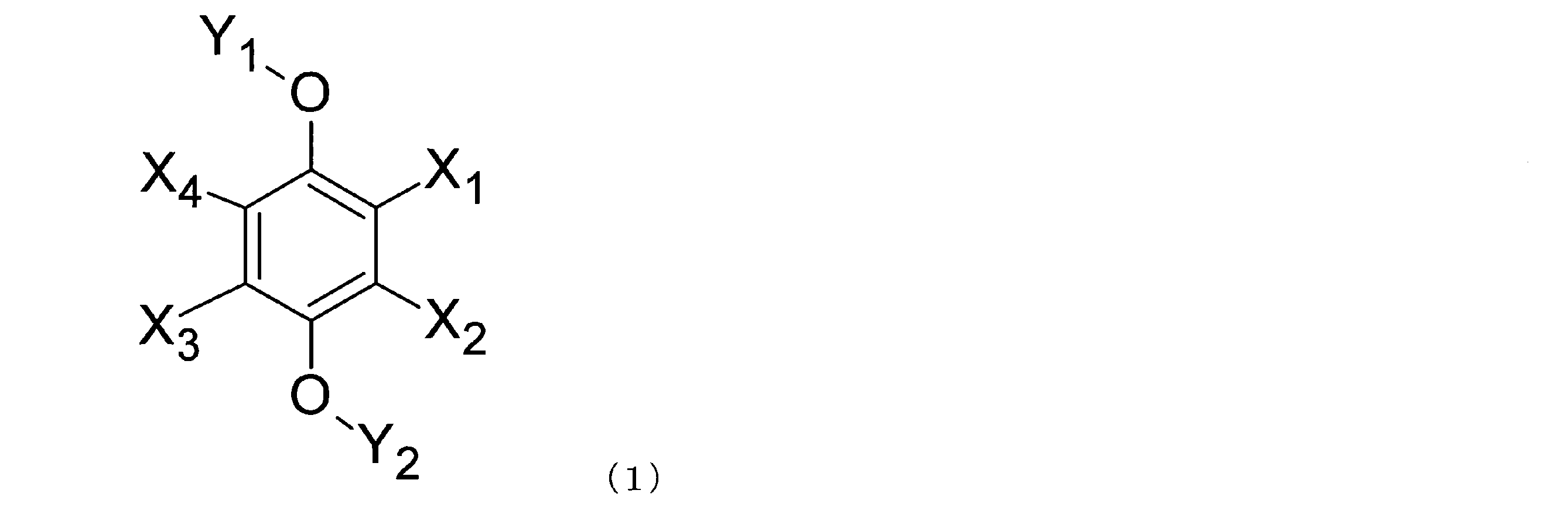
(式中、X1~X4は、それぞれ独立して、水素、弗素、塩素、臭素、シアノ基、ニトロ基、鎖状飽和炭化水素基、鎖状不飽和炭化水素基、環状飽和炭化水素基、環状不飽和炭化水素基、-COR1、または-N(R2)2を表し、R1およびR2は、それぞれ独立して、水素、鎖状飽和炭化水素基、鎖状不飽和炭化水素基、環状飽和炭化水素基、環状不飽和炭化水素基、シアノ基、ニトロ基およびそれらの組み合わせからなる群より選ばれる少なくとも1種である(ただし、X1、X2、X3、およびX4がすべて同時に水素である化合物を除く)。また、Y1およびY2は、それぞれ独立して、水素、鎖状飽和炭化水素基、鎖状不飽和炭化水素基、環状飽和炭化水素基、環状不飽和炭化水素基およびそれらの組み合わせからなる群より選ばれる少なくとも1種である。)
本開示の第4態様において、例えば、第1~第3態様のいずれか1つに係るフロー電池では、ベンゼン誘導体は、ベンゼン誘導体は、下記一般式(2)で示されるベンゼン誘導体である。

(式中、X1~X4は、それぞれ独立して、水素、弗素、塩素、臭素、シアノ基、ニトロ基、鎖状飽和炭化水素基、鎖状不飽和炭化水素基、環状飽和炭化水素基、環状不飽和炭化水素基、-COR1、または-N(R2)2を表し、R1およびR2は、それぞれ独立して、水素、鎖状飽和炭化水素基、鎖状不飽和炭化水素基、環状飽和炭化水素基、環状不飽和炭化水素基、シアノ基、ニトロ基およびそれらの組み合わせからなる群より選ばれる少なくとも1種である(ただし、X1、X2、X3、およびX4がすべて同時に水素である化合物を除く)。)
本開示の第5態様において、例えば、第1~第3態様のいずれか1つに係るフロー電池では、ベンゼン誘導体は、ベンゼン誘導体は、下記一般式(3)で示されるベンゼン誘導体である。
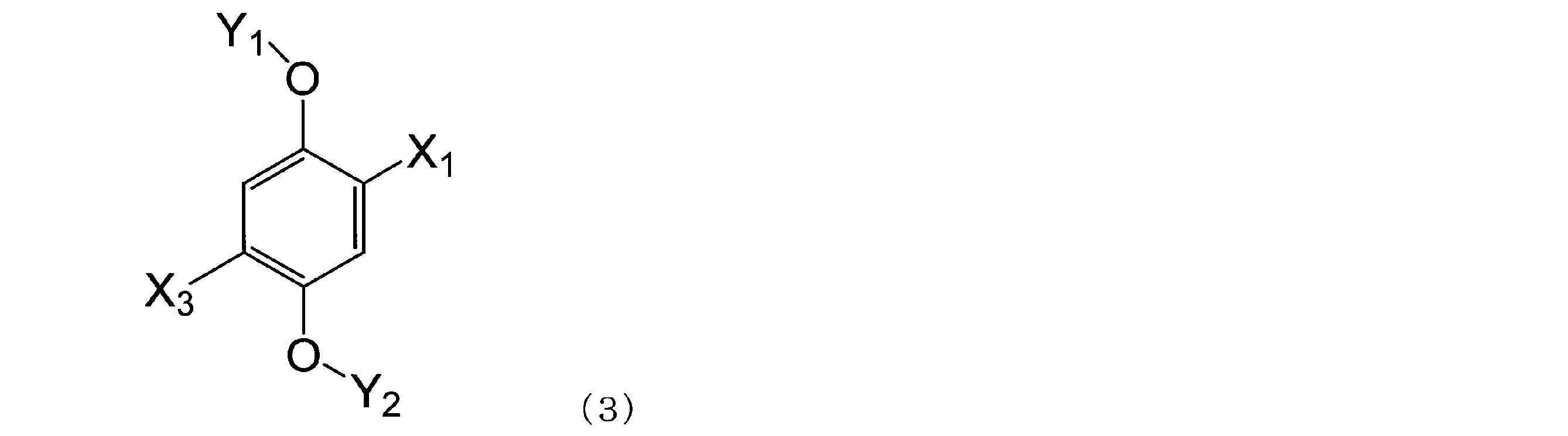
(式中、X1およびX3は、それぞれ独立して、水素、弗素、塩素、臭素、シアノ基、ニトロ基、鎖状飽和炭化水素基、鎖状不飽和炭化水素基、環状飽和炭化水素基、環状不飽和炭化水素基、-COR1、または-N(R2)2を表し、R1およびR2は、それぞれ独立して、水素、鎖状飽和炭化水素基、鎖状不飽和炭化水素基、環状飽和炭化水素基、環状不飽和炭化水素基、シアノ基、ニトロ基およびそれらの組み合わせからなる群より選ばれる少なくとも1種である(ただし、X1およびX3が同時に水素である化合物を除く)。また、Y1およびY2は、それぞれ独立して、鎖状飽和炭化水素基、鎖状不飽和炭化水素基、環状飽和炭化水素基、環状不飽和炭化水素基およびそれらの組み合わせからなる群より選ばれる少なくとも1種である。)
本開示の第6態様において、例えば、第1~第3態様のいずれか1つに係るフロー電池では、ベンゼン誘導体は、ベンゼン誘導体は、下記一般式(4)で示されるベンゼン誘導体である。

(式中、X1およびX3は、それぞれ独立して、水素、弗素、塩素、臭素、シアノ基、ニトロ基、鎖状飽和炭化水素基、鎖状不飽和炭化水素基、環状飽和炭化水素基、環状不飽和炭化水素基、-COR1、または-N(R2)2を表し、R1およびR2は、それぞれ独立して、水素、鎖状飽和炭化水素基、鎖状不飽和炭化水素基、環状飽和炭化水素基、環状不飽和炭化水素基、シアノ基、ニトロ基およびそれらの組み合わせからなる群より選ばれる少なくとも1種である(ただし、X1およびX3が同時に水素である化合物を除く)。)
本開示の第7態様において、例えば、第1~第6態様のいずれか1つに係るフロー電池では、ベンゼン誘導体は、1,4-ジ(tert-ブチル)-2,5-ジメトキシベンゼン、1,4-ジクロロ-2,5-ジメトキシベンゼン、1,4-ジフルオロ-2,5-ジメトキシベンゼン、および1,4-ジブロモ-2,5-ジメトキシベンゼンからなる群より選ばれる少なくとも1種である。
本開示の第8態様において、例えば、第1~第7態様のいずれか1つに係るフロー電池では、
ベンゼン誘導体は、第1酸化還元電位と第2酸化還元電位とを有し、
第1活物質の平衡電位は、前記第1酸化還元電位より高く、かつ、前記第2酸化還元電位より低い。
ベンゼン誘導体は、第1酸化還元電位と第2酸化還元電位とを有し、
第1活物質の平衡電位は、前記第1酸化還元電位より高く、かつ、前記第2酸化還元電位より低い。
本開示の第9態様において、例えば、第1~第8態様のいずれか1つに係るフロー電池では、
第1液体は、第1電極側放電メディエータを、さらに含み、
ベンゼン誘導体は、酸化電位を有し、
第1活物質の平衡電位は、前記ベンゼン誘導体の前記酸化電位より低く、
第1活物質の平衡電位は、前記第1電極側放電メディエータの平衡電位より高い。
第1液体は、第1電極側放電メディエータを、さらに含み、
ベンゼン誘導体は、酸化電位を有し、
第1活物質の平衡電位は、前記ベンゼン誘導体の前記酸化電位より低く、
第1活物質の平衡電位は、前記第1電極側放電メディエータの平衡電位より高い。
本開示の第10態様において、例えば、第1~第9態様のいずれか1つに係るフロー電池では、
第1循環機構は、第1収容部を備え、
第1活物質と前記第1液体とは、前記第1収容部に収容され、
前記第1循環機構は、前記第1電極と前記第1収容部との間で、前記第1液体を循環させ、
前記第1収容部において前記第1活物質と前記第1液体とが接触することにより、前記第1活物質と前記第1電極メディエータと間の酸化反応と還元反応とのうちの少なくとも一方が行われる。
第1循環機構は、第1収容部を備え、
第1活物質と前記第1液体とは、前記第1収容部に収容され、
前記第1循環機構は、前記第1電極と前記第1収容部との間で、前記第1液体を循環させ、
前記第1収容部において前記第1活物質と前記第1液体とが接触することにより、前記第1活物質と前記第1電極メディエータと間の酸化反応と還元反応とのうちの少なくとも一方が行われる。
本開示の第11態様において、例えば、第1~第10態様のいずれか1つに係るフロー電池では、
第1循環機構は、前記第1活物質の透過を抑制する第1透過抑制部を備え、
前記第1透過抑制部は、前記第1液体が前記第1収容部から前記第1電極に流出する経路に、設けられる。
第1循環機構は、前記第1活物質の透過を抑制する第1透過抑制部を備え、
前記第1透過抑制部は、前記第1液体が前記第1収容部から前記第1電極に流出する経路に、設けられる。
本開示の第12態様において、例えば、第1~第11態様のいずれか1つに係るフロー電池では、
充電メディエータと放電メディエータとを含む第2液体と、
前記第2液体に浸漬される第2電極と、
前記第2液体に浸漬される第2活物質と、
前記第1電極および前記第1液体と、前記第2電極および前記第2液体との間を隔離する隔離部と、をさらに備え、
前記充電メディエータの平衡電位は、前記第2活物質の平衡電位より低く、
前記放電メディエータの平衡電位は、前記第2活物質の平衡電位より高い。
充電メディエータと放電メディエータとを含む第2液体と、
前記第2液体に浸漬される第2電極と、
前記第2液体に浸漬される第2活物質と、
前記第1電極および前記第1液体と、前記第2電極および前記第2液体との間を隔離する隔離部と、をさらに備え、
前記充電メディエータの平衡電位は、前記第2活物質の平衡電位より低く、
前記放電メディエータの平衡電位は、前記第2活物質の平衡電位より高い。
本開示の第13態様において、例えば、第12態様に係るフロー電池では、
前記第2液体には、リチウムが溶解され、
前記第2活物質は、前記リチウムを吸蔵および放出する性質を有する物質であり、
充電時においては、前記充電メディエータは前記第2電極上において還元され、かつ、前記第2電極上において還元された前記充電メディエータは前記第2活物質により酸化されるとともに前記第2活物質は前記リチウムを吸蔵し、
放電時においては、前記リチウムを吸蔵した前記第2活物質は前記放電メディエータを還元するとともに前記第2活物質は前記リチウムを放出し、かつ、前記第2活物質により還元された前記放電メディエータは前記第2電極上において酸化される。
前記第2液体には、リチウムが溶解され、
前記第2活物質は、前記リチウムを吸蔵および放出する性質を有する物質であり、
充電時においては、前記充電メディエータは前記第2電極上において還元され、かつ、前記第2電極上において還元された前記充電メディエータは前記第2活物質により酸化されるとともに前記第2活物質は前記リチウムを吸蔵し、
放電時においては、前記リチウムを吸蔵した前記第2活物質は前記放電メディエータを還元するとともに前記第2活物質は前記リチウムを放出し、かつ、前記第2活物質により還元された前記放電メディエータは前記第2電極上において酸化される。
本開示の第14態様において、例えば、第12態様に係るフロー電池では、
前記充電時においては、前記放電メディエータは前記第2電極上において還元され、
前記放電時においては、前記充電メディエータは前記第2電極上において酸化される。
前記充電時においては、前記放電メディエータは前記第2電極上において還元され、
前記放電時においては、前記充電メディエータは前記第2電極上において酸化される。
本開示の第15態様において、例えば、第12~第14態様のいずれか1つに係るフロー電池では、
前記充電メディエータと前記放電メディエータとは、縮合芳香族化合物であり、
前記縮合芳香族化合物が溶解した前記第2液体は、リチウムの溶媒和電子を放出させ、前記リチウムをカチオンとして溶解する性質を有する。
前記充電メディエータと前記放電メディエータとは、縮合芳香族化合物であり、
前記縮合芳香族化合物が溶解した前記第2液体は、リチウムの溶媒和電子を放出させ、前記リチウムをカチオンとして溶解する性質を有する。
本開示の第16態様において、例えば、第12~第15態様のいずれか1つに係るフロー電池では、
前記充電メディエータは、フェナントレン、ビフェニル、o-ターフェニル、トリフェニレン、およびアントラセンからなる群より選ばれる少なくとも1種である。
前記充電メディエータは、フェナントレン、ビフェニル、o-ターフェニル、トリフェニレン、およびアントラセンからなる群より選ばれる少なくとも1種である。
本開示の第17態様において、例えば、第12~第16態様のいずれか1つに係るフロー電池では、
前記放電メディエータは、フェナントロリン、2,2’-ビピリジル、ベンゾフェノン、trans-スチルベン、4,4’-ビピリジル、3,3’-ビピリジル、2,4’-ビピリジル、2,3’-ビピリジル、cis-スチルベン、アセトフェノン、プロピオフェノン、ブチロフェノン、バレロフェノン、およびエチレンジアミンからなる群より選ばれる少なくとも1種である。
前記放電メディエータは、フェナントロリン、2,2’-ビピリジル、ベンゾフェノン、trans-スチルベン、4,4’-ビピリジル、3,3’-ビピリジル、2,4’-ビピリジル、2,3’-ビピリジル、cis-スチルベン、アセトフェノン、プロピオフェノン、ブチロフェノン、バレロフェノン、およびエチレンジアミンからなる群より選ばれる少なくとも1種である。
本開示の第18態様において、例えば、第12~第17態様のいずれか1つに係るフロー電池では、
第2収容部を備える第2循環機構をさらに備え、
前記第2活物質と前記第2液体とは、前記第2収容部に、収容され、
前記第2循環機構は、前記第2電極と前記第2収容部との間で、前記第2液体を循環させ、
前記第2収容部において前記第2活物質と前記第2液体とが接触することにより、前記第2活物質による前記充電メディエータの酸化反応と、前記第2活物質による前記放電メディエータの還元反応と、のうちの少なくとも一方が行われる。
第2収容部を備える第2循環機構をさらに備え、
前記第2活物質と前記第2液体とは、前記第2収容部に、収容され、
前記第2循環機構は、前記第2電極と前記第2収容部との間で、前記第2液体を循環させ、
前記第2収容部において前記第2活物質と前記第2液体とが接触することにより、前記第2活物質による前記充電メディエータの酸化反応と、前記第2活物質による前記放電メディエータの還元反応と、のうちの少なくとも一方が行われる。
本開示の第19態様において、例えば、第12~第18態様のいずれか1つに係るフロー電池では、
前記第2循環機構は、前記第2活物質の透過を抑制する第2透過抑制部を備え、
前記第2透過抑制部は、前記第2液体が前記第2収容部から前記第2電極に流出する経路に、設けられる。
前記第2循環機構は、前記第2活物質の透過を抑制する第2透過抑制部を備え、
前記第2透過抑制部は、前記第2液体が前記第2収容部から前記第2電極に流出する経路に、設けられる。
上述した第1から第19態様のフロー電池によれば、パラ位に結合したアルコキシ基の非共有電子対の存在による電子供与性の共役効果によりベンゼン誘導体のカチオンラジカルが安定化され可逆に充放電を行い、より高い放電電位を有するフロー電池を実現できる。
以下、本開示の実施形態が、図面を参照しながら、説明される。
(実施形態1)
図1は、実施形態1におけるフロー電池1000の概略構成を示すブロック図である。
図1は、実施形態1におけるフロー電池1000の概略構成を示すブロック図である。
実施形態1におけるフロー電池1000は、第1液体110と、第1電極210と、第1活物質310と、第1循環機構510と、を備える。
第1液体110は、第1電極メディエータ111が溶解した液体である。
第1電極210は、第1液体110に浸漬される電極である。
第1活物質310は、第1液体110に浸漬される活物質である。
第1循環機構510は、第1電極210と第1活物質310との間で第1液体110を循環させる機構である。
第1電極メディエータ111は、パラ位に少なくとも一組のアルコキシ基を有するベンゼン誘導体を含む。また、第1電極メディエータ111は、パラ位に少なくとも一組のアルコキシ基を有し、他位に水素原子以外の原子または置換基を少なくとも一つ含むものであってもよい。
ベンゼン誘導体の多くは、電気化学的酸化に伴い酸化分解または重合反応などを起こし可逆な酸化還元反応を起こすことができない。しかし、アルコキシ基等を有する誘導体においては、電気化学的酸化によって失われた電子を置換基中の酸素などの非共有電子対を有する原子から電子を補うことができる。さらに、図5に示すように、その置換基の結合位置がパラ位に存在する場合には、分子の対称性が向上しカチオンが安定化されるため、安定な一段階の酸化還元反応を示す。さらにそれぞれの場合において、置換基の電子吸引性が高いほど反応電位は高電位となる。
以上の構成によれば、高い放電電位と高いエネルギー密度と長いサイクル寿命とを有するフロー電池を実現できる。すなわち、以上の構成によれば、上記ベンゼン誘導体はその酸化還元電位が4V付近であるため、LiCoO2、LiNiO2、LiMn2O4などの充電メディエータ、LiNi0.5Mn1.5O4などの放電メディエータとして用いることができる。また、ベンゼン誘導体は1種のみで用いることもできる。したがって、平衡電位が高い活物質を第1活物質310として用いることが可能になり、より高い放電電位を有するフロー電池を実現できる。平衡電位が高い活物質は、例えば、3.8~4.5V vs. Li/Li+程度の活物質であってもよい。
また、以上の構成によれば、活物質を利用しながら、活物質そのものは循環させない構成のフロー電池を実現できる。このため、第1活物質310として、例えば、充放電反応に高容量な粉末活物質を、使用できる。これにより、高いエネルギー密度および高い容量を実現できる。
また、以上の構成によれば、粉末活物質そのものは循環させずに、第1電極メディエータ111が溶解した第1液体110のみを循環させることができる。このため、粉末活物質による配管などの詰まり等の発生を抑制できる。したがって、サイクル寿命が長いフロー電池を実現できる。
なお、実施形態1におけるフロー電池1000においては、ベンゼン誘導体は、下記一般式(1)で示されるベンゼン誘導体であってもよい。
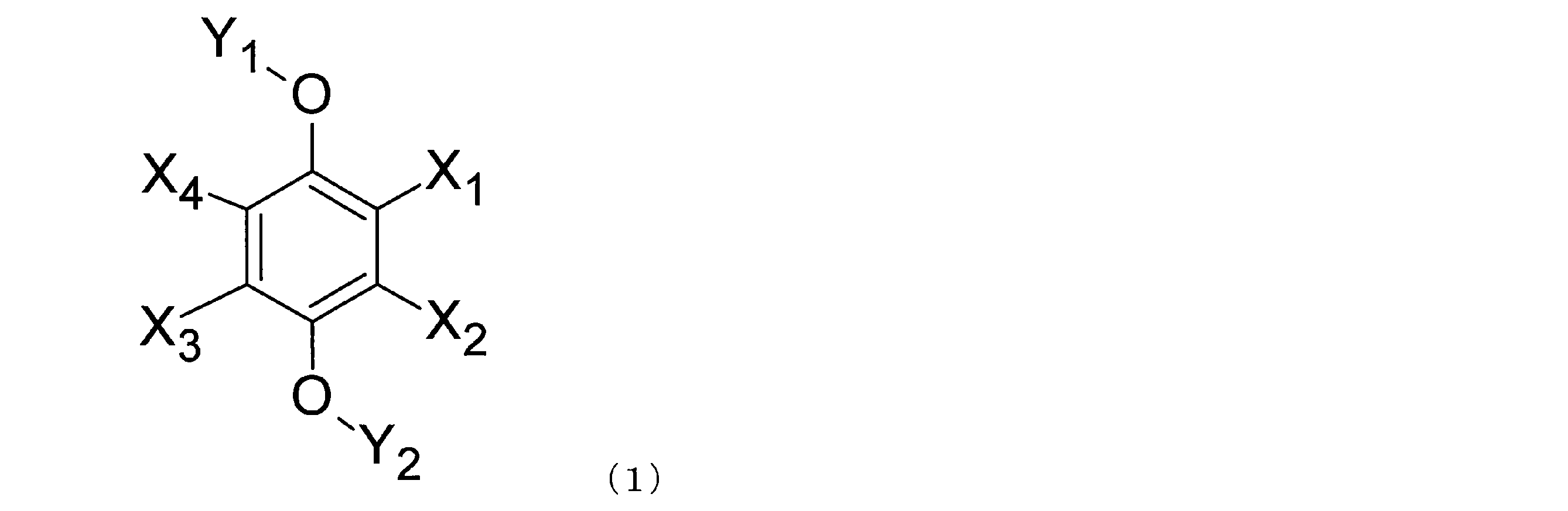
式中、X1~X4は、それぞれ独立して、水素、弗素、塩素、臭素、シアノ基、ニトロ基、鎖状飽和炭化水素基、鎖状不飽和炭化水素基、環状飽和炭化水素基、環状不飽和炭化水素基、-COR1、または-N(R2)2を表し、R1およびR2は、それぞれ独立して、水素、鎖状飽和炭化水素基、鎖状不飽和炭化水素基、環状飽和炭化水素基、環状不飽和炭化水素基、シアノ基、ニトロ基およびそれらの組み合わせからなる群より選ばれる少なくとも1種である。また、Y1およびY2はそれぞれ独立して、鎖状飽和炭化水素基、鎖状不飽和炭化水素基、環状飽和炭化水素基、環状不飽和炭化水素基およびそれらの組み合わせからなる群より選ばれる少なくとも1種である(ただし、X1、X2、X3、およびX4がすべて同時に水素である化合物を除く。)
以上の構成によれば、高電位固体正極活物質を用いることができ、高い放電電圧を有するフロー電池を実現できる。なお、鎖状飽和炭化水素基、鎖状不飽和炭化水素基、環状飽和炭化水素基、および環状不飽和炭化水素基は、酸素、窒素、硫黄、および珪素からなる群より選ばれる少なくとも1種の元素を含んでいてもよい。
また、実施形態1におけるフロー電池1000においては、一般式(1)で表されるベンゼン誘導体において、R1およびR2は、ホウ素、窒素、酸素、弗素、珪素、燐、硫黄、塩素、臭素、およびヨウ素からなる群より選ばれる少なくとも1種の元素(非金属元素)を含んでもよい。X1~X4、R1、R2、Y1、およびY2に係る鎖状飽和炭化水素基としては、炭素原子数1~10の鎖状飽和炭化水素基であってもよい。炭素原子数1~10の鎖状飽和炭化水素基としては、メチル基、エチル基、n-プロピル基、イソプロピル基、n-ブチル基、イソブチル基、n-ペンチル基、n-ヘキシル基、n-ヘプチル基、n-オクチル基、n-ノニル基、n-デシル基などが挙げられる。X1~X4、R1、R2、Y1、およびY2に係る鎖状不飽和炭化水素基としては、炭素原子数2~6の鎖状不飽和炭化水素基であってもよい。炭素原子数2~6の鎖状不飽和炭化水素基としては、ビニル基、1-プロペニル基、2-プロペニル基、1-メチル-1-エテニル基、1-ブテニル基、2-ブテニル基、3-ブテニル基、2-メチル-1-プロペニル基、1-エチルエテニル基、1-メチル-1-プロペニル基、1-メチル-2-プロペニル基、1-ペンテニル基、2-ペンテニル基、3-ペンテニル基、4-ペンテニル基、1-n-プロピルエテニル基、1,1-ジメチル-2-プロペニル基、1-i-プロピルエテニル基、1,2-ジメチル-1-プロペニル基、1-ヘキセニル基、2-ヘキセニル基、3-ヘキセニル基、4-ヘキセニル基、5-ヘキセニル基、1-メチル-1-ペンテニル基などが挙げられる。X1~X4、R1、R2、Y1、およびY2に係る環状飽和炭化水素基としては、炭素原子数5~12の環状飽和炭化水素基であってもよい。炭素原子数5~12の環状飽和炭化水素基としては、シクロペンチル基、シクロヘキシル基、シクロヘプチル基、シクロオクチル基、シクロデシル基、シクロウンデシル基、シクロドデシル基などが挙げられる。X1~X4、R1、R2、Y1、およびY2に係る環状不飽和炭化水素基としては、炭素原子数5~12の環状不飽和炭化水素基であってもよい。炭素原子数5~12の環状不飽和炭化水素基としては、シクロペンテニル基、シクロヘキセニル基、シクロオクテニル基、シクロウンデシニル基、シクロドデシニル基、シクロヘキサジエニル基、シクロオクタジエニル基、シクロドデカジエニル基、シクロドデカトリエニル基等の側鎖を有するまたは有しない脂肪族環状不飽和炭化水素基;トルエン、キシレン等の側鎖を有する芳香族炭化水素基が挙げられる。鎖状飽和炭化水素基、鎖状不飽和炭化水素基、環状飽和炭化水素基、および環状不飽和炭化水素基は、エーテル結合を含んでいてもよい。
以上の構成によれば、パラ位に結合したアルコキシ基の非共有電子対の存在による電子供与性の共役効果によりベンゼン誘導体のカチオンラジカルが安定化され可逆に充放電を行い、より高い放電電位を有するフロー電池を実現できる。
また、実施形態1におけるフロー電池1000においては、下記一般式(2)で示されるベンゼン誘導体であってもよい。

式中、X1~X4は、それぞれ独立して、水素、弗素、塩素、臭素、シアノ基、ニトロ基、鎖状飽和炭化水素基、鎖状不飽和炭化水素基、環状飽和炭化水素基、環状不飽和炭化水素基、-COR1、または-N(R2)2を表し、R1およびR2は、それぞれ独立して、水素、鎖状飽和炭化水素基、鎖状不飽和炭化水素基、環状飽和炭化水素基、環状不飽和炭化水素基、シアノ基、ニトロ基およびそれらの組み合わせからなる群より選ばれる少なくとも1種である(ただし、X1、X2、X3、およびX4がすべて同時に水素である化合物を除く)。X1~X4、R1、およびR2に係る、鎖状飽和炭化水素基、鎖状不飽和炭化水素基、環状飽和炭化水素基は、一般式(1)で説明したものと同様である。
以上の構成によれば、より高い放電電位を有するフロー電池を実現できる。
また、実施形態1におけるフロー電池1000においては、ベンゼン誘導体は、下記一般式(3)で示されるベンゼン誘導体であってもよい。
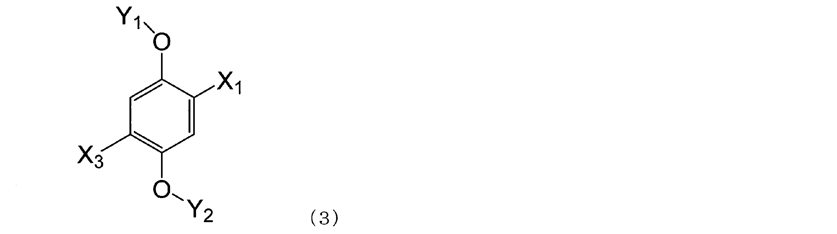
式中、X1、およびX3は、それぞれ独立して、水素、弗素、塩素、臭素、シアノ基、ニトロ基、鎖状飽和炭化水素基、鎖状不飽和炭化水素基、環状飽和炭化水素基、環状不飽和炭化水素基、-COR1、または-N(R2)2を表し、R1およびR2は、それぞれ独立して、水素、鎖状飽和炭化水素基、鎖状不飽和炭化水素基、環状飽和炭化水素基、環状不飽和炭化水素基、シアノ基、ニトロ基およびそれらの組み合わせからなる群より選ばれる少なくとも1種である(ただし、X1およびX3が同時に水素である化合物を除く)。Y1およびY2はそれぞれ独立して鎖状飽和炭化水素基、鎖状不飽和炭化水素基、環状飽和炭化水素基、環状不飽和炭化水素基およびそれらの組み合わせからなる群より選ばれる少なくとも1種である。
以上の構成によれば、より高い放電電位を有するフロー電池を実現できる。
また、実施形態1におけるフロー電池1000においては、一般式(3)で表されるベンゼン誘導体において、また、R1およびR2は、ホウ素、窒素、酸素、弗素、珪素、燐、硫黄、塩素、臭素、およびヨウ素からなる群より選ばれる少なくとも1種の元素(非金属元素)を含んでもよい。X1、X3、R1、R2、Y1、およびY2に係る、鎖状飽和炭化水素基、鎖状不飽和炭化水素基、環状飽和炭化水素基は、一般式(1)で説明したものと同様である。
また、実施形態1におけるフロー電池1000においては、ベンゼン誘導体は、下記一般式(4)で示されるベンゼン誘導体であってもよい。

式中、X1、およびX3は、それぞれ独立して、水素、弗素、塩素、臭素、シアノ基、ニトロ基、鎖状飽和炭化水素基、鎖状不飽和炭化水素基、環状飽和炭化水素基、環状不飽和炭化水素基、-COR1、または-N(R2)2を表し、R1およびR2は、それぞれ独立して、水素、鎖状飽和炭化水素基、鎖状不飽和炭化水素基、環状飽和炭化水素基、環状不飽和炭化水素基、シアノ基、ニトロ基およびそれらの組み合わせからなる群より選ばれる少なくとも1種である(ただし、X1およびX3が同時に水素である化合物を除く)。X1、X3、R1、およびR2に係る、鎖状飽和炭化水素基、鎖状不飽和炭化水素基、環状飽和炭化水素基は、一般式(1)で説明したものと同様である。
以上の構成によれば、より高い放電電位を有するフロー電池を実現できる。
また、実施形態1におけるフロー電池1000においては、ベンゼン誘導体は、1,4-ジ(tert-ブチル)-2,5-ジメトキシベンゼン、1,4-ジクロロ-2,5-ジメトキシベンゼン、1,4-ジフルオロ-2,5-ジメトキシベンゼン、および1,4-ジブロモ-2,5-ジメトキシベンゼンからなる群より選ばれる少なくとも1種であってもよい。
以上の構成によれば、より高い放電電位を有するフロー電池を実現できる。
下記表1は、第1電極メディエータ111として用いられうるベンゼン誘導体の電位の測定結果を示す。

1Mの電解質を溶媒に溶解させた電解液を準備した。電解質としては、LiBF4を用いた。溶媒としては、プロピレンカーボネート(PC)を用いた。電解質と溶媒の組み合わせを、表1に示す。当該電解液に表1に示される各ベンゼン誘導体をそれぞれの5mM溶解することで、表1に示される各ベンゼン誘導体に対応する電解液を得た。それぞれの電解液と対極と作用極と参照極とで、表1に示される各ベンゼン誘導体に対応する電位測定用セルを作製した。対極には、1×1cmのPt箔を用いた。作用極には、電気化学測定用グラッシーカーボン電極(φ6mm)を用いた。参照極には、銀線(Ag/Ag+)を用いた。それぞれの電位測定用セルを用いて、サイクリックボルタンメトリ(CV)測定により、表1に示される各ベンゼン誘導体の充放電電位を測定した。表1は、測定された充放電電位がリチウム金属基準で換算された電位(V vs. Li/Li+)を示す。
表1より、ベンゼン誘導体は4.0~4.4(V vs. Li/Li+)に酸化還元電位を有する。そのため、平衡電位が充電電位である第1酸化電位より低い平衡電位を有する正極固体活物質に対する充電メディエータとして用いることができる。また、第1酸化電位と、充電電位である第1還元電位の間に平衡電位を有する正極固体活物質に対しては1種で充放電メディエータとして用いることができる。この場合、1段階目の酸化電位(第1酸化電位:E1ox(V vs. Li/Li+))がメディエータの充電電位となり、1段階目の還元電位(第1還元電位:E1red(V vs. Li/Li+))は、メディエータの放電電位となる。
ベンゼン誘導体である、1,4-ジ(tert-ブチル)-2,5-ジメトキシベンゼン、1,4-ジクロロ-2,5-ジメトキシベンゼン、1,4-ジフルオロ-2,5-ジメトキシベンゼン、および1,4-ジブロモ-2,5-ジメトキシベンゼンは、テトラチアフルバレンまたは従来の正極放電メディエータと比較して、第1酸化還元電位がおよそ0.5V高い。
フロー電池の放電電位は、正極側の放電メディエータの電位により決まる。このため、高電位側に放電電位を有する、上述の実施形態1におけるベンゼン誘導体であれば、より高い放電電位を有するフロー電池を実現できる。
なお、実施形態1におけるフロー電池1000においては、第1電極メディエータ111は、上述の実施形態1における1種のベンゼン誘導体のみを含んでもよい。
また、実施形態1におけるフロー電池1000においては、第1電極メディエータ111は、上述の実施形態1におけ2種以上のベンゼン誘導体を含んでもよい。
上述のように、実施形態1におけるベンゼン誘導体は、第1酸化電位E1oxと第1還元電位E1redとを有する。
このとき、第1活物質310の平衡電位(V vs. Li/Li+)は、第1酸化電位E1oxより低くてもよく、かつ、第1還元電位E1redより高くてもよい。
以上の構成によれば、第1還元電位E1redより高い平衡電位を有する活物質を第1活物質310として用いることで、実施形態1におけるベンゼン誘導体を放電メディエータとして機能させることができる。言い換えれば、第1還元電位E1redより貴な電位を示す活物質を第1活物質310として用いることで、実施形態1におけるベンゼン誘導体を放電メディエータとして機能させることができる。また、第1酸化電位E1oxより低い平衡電位を有する活物質を第1活物質310として用いることで、実施形態1におけるベンゼン誘導体を充電メディエータとして機能させることができる。言い換えれば、第1酸化電位E1oxより卑な電位を示す活物質を第1活物質310として用いることで、実施形態1におけるベンゼン誘導体を充電メディエータとして機能させることができる。
また、実施形態1におけるフロー電池1000においては、第1活物質310は、LixMyO2で表される金属酸化物であってもよい。ここで、Mは、Ni、Mn、およびCoからなる群より選ばれる少なくとも1種である。xおよびyは、任意の値である。当該金属酸化物は、3.8~4.4Vに平衡電位を有する。
また、実施形態1におけるフロー電池1000においては、第1活物質310は、LiFePO4、LiMnO2、LiMn2O4、およびLiCoO2からなる群より選ばれる少なくとも1種であってもよい。
ここで、LiCoO2の平衡電位は、3.9V vs. Li/Li+である。このとき、LiCoO2の平衡電位より貴な電位に放電電位を有し、かつ、LiCoO2の平衡電位より卑な電位に充電電位を有する化合物を、充放電メディエータである第1電極メディエータ111として使用すれば、LiCoO2を活物質としたメディエータ型の正極を構成できる。このとき、LiCoO2の平衡電位と第1電極メディエータ111の充放電電位との電位差がより少ないほうが、充放電エネルギー効率に優れる。例えば、第1電極メディエータ111の放電電位がLiCoO2の平衡電位より低く、かつ、LiCoO2の平衡電位により近い場合には、フロー電池の放電電位はより高くなる。一方で、1種のメディエータのみで条件を満たせない場合には充放電を行うために複数種のメディエータを用いる必要がある。
したがって、第1活物質310としてLiCoO2を用いる場合、第1電極メディエータ111の充電メディエータとして、少なくとも一種のベンゼン誘導体を用い、かつ放電メディエータとして、3.78V vs. Li/Li+で可逆に一段階以上の酸化還元反応を行う複素芳香環類およびシクロペンタジエニル化合物を用いることでフロー電池の放電電位をより高くできる。充電メディエータとしてのベンゼン誘導体は、1,4-ジ(tert-ブチル)-2,5-ジメトキシベンゼン、1,4-ジクロロ-2,5-ジメトキシベンゼン、1,4-ジフルオロ-2,5-ジメトキシベンゼン、および1,4-ジブロモ-2,5-ジメトキシベンゼンからなる群より選ばれる少なくとも1種であってもよい。放電メディエータとしてのシクロペンタジエニル化合物は、1,1’-ジブロモフェロセンなどであってもよい。この場合、正極固体活物質として3.5V付近に放電電位を有するLiFePO4を用いる場合と比較して、およそ0.4~0.5V程度、放電電位を高めることができる。
ベンゼン誘導体は、充電メディエータとして、用いられてもよい。この場合、正極固体活物質の平衡電位より卑な酸化還元電位を有するメディエータ種が、放電メディエータとして、用いられてもよい。
すなわち、実施形態1におけるフロー電池1000においては、第1液体110には、第1電極側放電メディエータが、さらに溶解していてもよい。言い換えれば、第1液体110は、第1電極側放電メディエータをさらに含んでもよい。
このとき、第1活物質310の平衡電位は、ベンゼン誘導体の酸化電位Eoxより低くてもよい。
さらに、第1活物質310の平衡電位は、第1電極側放電メディエータの平衡電位より高くてもよい。
以上の構成によれば、ベンゼン誘導体の酸化電位Eoxより低い平衡電位を有する活物質を第1活物質310として用いることで、実施形態1におけるベンゼン誘導体を充電メディエータとして機能させることができる。言い換えれば、酸化電位Eoxより卑な電位を示す活物質を第1活物質310として用いることで、実施形態1におけるベンゼン誘導体を充電メディエータとして機能させることができる。また、第1電極側放電メディエータの平衡電位より高い平衡電位を有する活物質を第1活物質310として用いることで、第1電極側放電メディエータを放電メディエータとして機能させることができる。言い換えれば、第1電極側放電メディエータの平衡電位より卑な電位を示す活物質を第1活物質310として用いることで、第1電極側放電メディエータを放電メディエータとして機能させることができる。
第1電極側放電メディエータとしては、テトラチアフルバレン、トリフェニルアミンなどの複素芳香環類、および/または、フェロセンなどをはじめとするシクロペンタジエニル化合物などでもよい。
ベンゼン誘導体は、放電メディエータとして用いられてもよい。この場合は、正極固体活物質の平衡電位より貴な酸化還元電位を有するメディエータ種が、充電メディエータとして、用いられてもよい。
なお、第1活物質310として、固体の活物質が用いられてもよい。固体の活物質は、例えば、粉末状の活物質であってもよい。第1活物質310を加工無しの粉末状態でタンクに充填する場合には、製造を簡便化でき、かつ、製造コストを低減できる。
また、第1活物質310として、ペレット状の活物質が用いられてもよい。ペレット状の活物質は、例えば、粉末をペレット成型した状態の活物質であってもよい。第1活物質310をペレット状でタンクに充填する場合には、製造を簡便化でき、かつ、製造コストを低減できる。
また、第1活物質310として、公知のバインダーによりペレット状に固められた活物質が用いられてもよい。バインダーは、例えば、ポリフッ化ビニリデン、ポリプロピレン、ポリエチレン、ポリイミド、などであってもよい。
なお、第1活物質310は、第1液体110に不溶性の物質であってもよい。これにより、第1液体110とともに第1電極メディエータ111は循環させるが、第1活物質310は循環させない構成のフロー電池を実現できる。
実施形態1におけるフロー電池1000においては、第1液体110は、プロピレンカーボネート(PC)、エチレンカーボネート(EC)、γ-ブチロラクトンジメチルカーボネート(DMC)、エチルメチルカーボネート(EMC)、フルオロエチレンカーボネート(FEC)、およびジエチルカーボネート(DEC)からなる群より選ばれる少なくとも1種であってもよい。また、第1液体110は、エーテル溶媒であってもよい。エーテル溶媒は、例えば、テトラヒドロフラン(THF)、2-メチルテトラヒドロフラン(2MeTHF)、ジメトキシエタン(DME)、1,3-ジオキサン(1,3DO)、4-メチル-1,3-ジオキサン(4Me1,3DO)であってもよい。
実施形態1におけるフロー電池1000においては、第1液体110は、上述の第1液体110の材料を溶媒とした、電解質を含む電解液であってもよい。当該電解質(塩)は、LiBF4、LiPF6、およびLiN(CF3SO2)2からなる群より選ばれる少なくとも1種であってもよい。また、当該溶媒は、その誘電率が高く、かつ、Liイオンとの反応性が低く、かつ、その電位窓が4V付近までであってもよい。
なお、実施形態1におけるフロー電池1000においては、第1電極210は正極であり、かつ、第2電極220は負極であってもよい。
なお、第2電極220として、相対的に電位の高い電極を用いれば、第1電極210は、負極にもなりうる。
すなわち、第1電極210は負極であり、かつ、第2電極220は正極であってもよい。
なお、実施形態1におけるフロー電池1000においては、例えば、第1液体110が第1電極210に接触することにより、第1電極メディエータ111は、第1電極210により、酸化または還元される。
第1電極210は、第1電極メディエータ111の反応場として作用する表面を有する電極であってもよい。
この場合、第1電極210として、第1液体110に対して安定な材料が用いられうる。第1液体110に対して安定な材料は、例えば、第1液体110に不溶性の材料であってもよい。さらに、第1電極210として、電極反応である電気化学反応に対して安定な材料が用いられうる。例えば、第1電極210として、金属、カーボン、などが用いられうる。金属は、例えば、ステンレス鋼、鉄、銅、ニッケルなどであってもよい。
第1電極210は、その表面積を増大させた構造を有するものであってもよい。表面積を増大させた構造を有するものは、例えば、メッシュ、不織布、表面粗化処理板、焼結多孔体、などであってもよい。これによれば、第1電極210の比表面積が大きくなる。これにより、第1電極メディエータ111の酸化反応または還元反応を、より進行し易くできる。
第2電極220は、集電体と、集電体上に設けられた活物質と、を備える構成であってもよい。これにより、例えば、高容量な活物質を用いることができる。第2電極220の活物質としては、リチウムイオンを可逆に吸蔵および放出する特性を有する化合物が用いられうる。
また、第2電極220は、リチウム金属であってもよい。第2電極220として、リチウム金属を用いた場合、金属正極としての溶解析出の制御が容易となり、かつ、高容量を実現できる。
なお、実施形態1におけるフロー電池1000は、隔離部400をさらに備えてもよい。
隔離部400は、第1電極210および第1液体110と第2電極220との間を隔離する。
隔離部400は、公知の二次電池に用いられる、微多孔膜および/または多孔体であってもよい。
また、隔離部400は、ガラス繊維を不織布に織り込んだガラスペーパーなどの多孔膜であってもよい。
また、隔離部400は、リチウムイオン伝導性などのイオン伝導性を有する隔膜であってもよい。例えば、隔離部400は、イオン交換樹脂膜、または、固体電解質膜、などであってもよい。イオン交換樹脂膜は、例えば、カチオン交換膜、アニオン交換膜などであってもよい。
第1循環機構510は、第1電極210と第1活物質310との間で、第1液体110を循環させる機構である。
以上の構成によれば、第1液体110とともに第1電極メディエータ111を、第1電極210と第1活物質310との間で、循環させることができる。これにより、各材料間の酸化反応および還元反応を、より効率的に、行うことができる。
第1循環機構510は、例えば、配管、タンク、ポンプ、バルブ、などを備える機構であってもよい。
第1循環機構510の具体的な一例としては、後述する実施形態2の構成などが、挙げられる。
<充放電プロセスの説明>
実施形態1におけるフロー電池1000の充放電プロセスが、以下に、説明される。
実施形態1におけるフロー電池1000の充放電プロセスが、以下に、説明される。
なお、具体的に、下記の構成である動作例が例示されながら、充放電プロセスが説明される。
本動作例では、第1電極210は、正極であり、カーボンブラックである。
本動作例では、第1液体110は、第1電極メディエータ111が溶解したエーテル溶液である。
本動作例では、第1電極メディエータ111は、上述された実施形態1のベンゼン誘導体(以下、dialkoxybenzene:DABと表記される)である。
本動作例では、第1活物質310は、コバルト酸リチウム(LiCoO2)である。
本動作例では、第2電極220は、負極であり、リチウム金属である。
[充電プロセスの説明]
まず、充電反応が、説明される。
まず、充電反応が、説明される。
第1電極210と第2電極220との間に、電圧が印加されることにより、充電が行われる。
(負極側の反応)
電圧の印加により、負極である第2電極220にフロー電池の外部から電子が供給される。これにより、負極である第2電極220では、還元反応が起こる。すなわち、負極は、充電状態となる。
電圧の印加により、負極である第2電極220にフロー電池の外部から電子が供給される。これにより、負極である第2電極220では、還元反応が起こる。すなわち、負極は、充電状態となる。
例えば、本動作例では、下記の反応が生じる。
Li+ + e- → Li
Li+ + e- → Li
(正極側の反応)
電圧の印加により、正極である第1電極210では、第1電極メディエータ111の酸化反応が起こる。すなわち、第1電極210の表面において、第1電極メディエータ111が酸化される。これにより、第1電極210からフロー電池の外部に電子が放出される。
電圧の印加により、正極である第1電極210では、第1電極メディエータ111の酸化反応が起こる。すなわち、第1電極210の表面において、第1電極メディエータ111が酸化される。これにより、第1電極210からフロー電池の外部に電子が放出される。
例えば、本動作例では、下記の反応が生じる。
DAB → DAB+ + e-
DAB → DAB+ + e-
第1循環機構510により、第1電極210により酸化された第1電極メディエータ111が、第1活物質310が設けられた場所まで、移動させられる。すなわち、第1循環機構510により、第1電極210により酸化された第1電極メディエータ111が、第1活物質310が設けられた場所まで、供給される。
このとき、第1電極210上において酸化された第1電極メディエータ111は、第1活物質310により還元される。すなわち、第1活物質310は、第1電極メディエータ111によって、酸化される。これにより、第1活物質310はリチウムイオンを放出する。
例えば、本動作例では、下記の反応が生じる。
LiCoO2 + DAB+ → CoO2 + Li+ + DAB
LiCoO2 + DAB+ → CoO2 + Li+ + DAB
第1循環機構510により、第1活物質310により還元された第1電極メディエータ111が、第1電極210が設けられた場所まで、移動させられる。すなわち、第1循環機構510により、第1活物質310により還元された第1電極メディエータ111が、第1電極210が設けられた場所まで、供給される。
このとき、第1電極210の表面において、第1電極メディエータ111が酸化される。
例えば、本動作例では、下記の反応が生じる。
DAB → DAB+ + e-
DAB → DAB+ + e-
なお、第1活物質310から発生したリチウムイオン(Li+)の一部は、隔離部400を通じて、第2電極220側に移動しうる。
以上のように、第1電極メディエータ111は、循環を含めたトータル反応で見ると、変化していない。
一方で、第1電極210と離れた場所に位置する第1活物質310が、充電状態となる。
以上のように、第1電極210側においては、DAB+ が第1電極側充電メディエータとして充電メディエータの役割を果たす。
完全充電状態では、第1液体110にはDAB+が存在し、第1活物質310はCoO2となる。このとき、充電電位は、DAB+への酸化電位で決定される。
以上の充電反応は、第1活物質310が完全充電状態となる、または、第2電極220が完全充電状態となる、のどちらかに到達するまで、進行しうる。
[放電プロセスの説明]
次に、満充電からの放電反応が、説明される。
次に、満充電からの放電反応が、説明される。
満充電では、第1活物質310と第2電極220とは、充電状態となっている。
放電反応では、第1電極210と第2電極220との間から、電力が取り出される。
(負極側の反応)
負極である第2電極220では、酸化反応が起こる。すなわち、負極は、放電状態となる。
負極である第2電極220では、酸化反応が起こる。すなわち、負極は、放電状態となる。
これにより、第2電極220からフロー電池の外部に電子が放出される。
例えば、本動作例では、下記の反応が生じる。
Li → Li+ + e-
Li → Li+ + e-
(正極側の反応)
電池の放電により、正極である第1電極210にフロー電池の外部から電子が供給される。
電池の放電により、正極である第1電極210にフロー電池の外部から電子が供給される。
これにより、第1電極210上では、第1電極メディエータ111の還元反応が起こる。
すなわち、第1電極210の表面において、第1電極メディエータ111が還元される。
例えば、本動作例では、下記の反応が生じる。
DAB+ + e-→ DAB
DAB+ + e-→ DAB
第1循環機構510により、第1電極210により還元された第1電極メディエータ111が、第1活物質310が設けられた場所まで、移動させられる。すなわち、第1循環機構510により、第1電極210により還元された第1電極メディエータ111が、第1活物質310が設けられた場所まで、供給される。
このとき、第1電極210上において還元された第1電極メディエータ111は、第1活物質310により、酸化される。すなわち、第1活物質310は、第1電極メディエータ111により、還元される。これにより、第1活物質310は、リチウムを吸蔵する。
例えば、本動作例では、下記の反応が生じる。
CoO2 + Li+ + DAB→ LiCoO2 + DAB+
CoO2 + Li+ + DAB→ LiCoO2 + DAB+
第1循環機構510により、第1活物質310により酸化された第1電極メディエータ111が、第1電極210が設けられた場所まで、移動させられる。すなわち、第1循環機構510により、第1活物質310により酸化された第1電極メディエータ111が、第1電極210が設けられた場所まで、供給される。
このとき、第1電極210の表面において、第1電極メディエータ111が還元される。
例えば、本動作例では、下記の反応が生じる。
DAB+ + e- → DAB
DAB+ + e- → DAB
なお、リチウムイオン(Li+)の一部は、隔離部400を通じて、第2電極220側から供給されうる。
以上のように、第1電極メディエータ111は、循環を含めたトータル反応で見ると、変化していない。
一方で、第1電極210と離れた場所に位置する第1活物質310が、放電状態となる。
以上のように、第1電極210側においては、DABが第1電極側放電メディエータとして放電メディエータの役割を果たす。
完全放電状態では、第1液体110にはDABが存在し、第1活物質310はLiCoO2となる。このとき、放電電位はDABへの還元電位で決定される。
以上の放電反応は、第1活物質310が完全放電状態となる、または、第2電極220が完全放電状態となる、のどちらかに到達するまで、進行しうる。
(実施形態2)
以下、実施形態2が説明される。なお、上述の実施形態1と重複する説明は、適宜、省略される。
以下、実施形態2が説明される。なお、上述の実施形態1と重複する説明は、適宜、省略される。
図2は、実施形態2におけるフロー電池2000の概略構成を例示的に示す模式図である。
実施形態2におけるフロー電池2000は、上述の実施形態1におけるフロー電池1000の構成に加えて、下記の構成を備える。
実施形態2におけるフロー電池2000においては、第1循環機構510は、第1収容部511を備える。
第1活物質310と第1液体110とは、第1収容部511に、収容される。
第1循環機構510は、第1電極210と第1収容部511との間で、第1液体110を循環させる。
第1収容部511において第1活物質310と第1液体110とが接触することにより、第1活物質310による第1電極メディエータ111の酸化反応と還元反応とのうちの少なくとも一方が行われる。
以上の構成によれば、第1収容部511において、第1液体110と第1活物質310とを、接触させることができる。これにより、例えば、第1液体110と第1活物質310との接触面積を、より大きくできる。また、第1液体110と第1活物質310との接触時間を、より長くできる。このため、第1活物質310による第1電極メディエータ111の酸化反応および還元反応を、より効率的に、行うことができる。
なお、実施形態2においては、第1収容部511は、例えば、タンクであってもよい。
また、第1収容部511は、例えば、充填された第1活物質310の隙間に、第1電極メディエータ111が溶解した第1液体110を、収容していてもよい。
また、第1収容部511は、例えば、充填された第1活物質310の隙間に、第1電極メディエータ111が溶解した第1液体110を、収容していてもよい。
また、図2に示されるように、実施形態2におけるフロー電池2000は、電気化学反応部600と、正極端子211と、負極端子221と、をさらに備えてもよい。
電気化学反応部600は、隔離部400により、正極室610と負極室620とに、分離されている。
正極室610には、正極となる電極が、配置される。図2では、正極室610には、第1電極210が、配置される。
正極端子211は、正極となる電極に、接続される。
負極室620には、負極となる電極が、配置される。図2では、負極室620には、第2電極220が、配置される。
負極端子221は、負極となる電極に、接続される。
正極端子211と負極端子221とは、例えば、充放電装置に接続される。充放電装置により、正極端子211と負極端子221との間に電圧が印加される、または、正極端子211と負極端子221との間から電力が取り出される。
また、図2に示されるように、実施形態2におけるフロー電池2000においては、第1循環機構510は、配管513と、配管514と、ポンプ515と、を備えてもよい。
配管513の一端は、第1収容部511の第1液体110の流出口側に、接続される。
配管513の別の一端は、正極室610と負極室620とのうち、第1電極210が配置される方に、接続される。図2では、配管513の別の一端は、正極室610に接続される。
配管514の一端は、正極室610と負極室620とのうち、第1電極210が配置される方に、接続される。図2では、配管514の一端は、正極室610に、接続される。
配管514の別の一端は、第1収容部511の第1液体110の流入口側に、接続される。
ポンプ515は、例えば、配管514に設けられる。または、ポンプ515は、配管513に設けられてもよい。
なお、実施形態2におけるフロー電池2000においては、第1循環機構510は、第1透過抑制部512を備えてもよい。
第1透過抑制部512は、第1活物質310の透過を抑制する。
第1透過抑制部512は、第1液体110が第1収容部511から第1電極210に流出する経路に、設けられる。図2では、第1透過抑制部512は、配管513に設けられる。
以上の構成によれば、第1活物質310が第1収容部511以外(例えば、第1電極210側)へ流出することを抑制できる。すなわち、第1活物質310は、第1収容部511に留まる。これにより、第1活物質310そのものは循環させない構成のフロー電池を実現できる。このため、第1循環機構510の部材の内部の第1活物質310による目詰まりを防止できる。第1循環機構510の部材は、例えば、配管であってもよい。また、第1活物質310が第1電極210側に流出することによる抵抗損失の発生を防止できる。
第1透過抑制部512は、例えば、第1収容部511と配管513との接合部に、設けられてもよい。
第1透過抑制部512は、例えば、第1活物質310を濾過するフィルターであってもよい。このとき、フィルターは、第1活物質310の粒子の最小粒径より小さい孔を有する部材であってもよい。フィルターの材料としては、第1活物質310および第1液体110などと反応しない材料が用いられうる。フィルターは、例えば、ガラス繊維濾紙、ポリプロピレン不織布、ポリエチレン不織布、金属リチウムと反応しない金属メッシュ、など、であってもよい。
以上の構成によれば、第1収容部511の内部において、第1液体110の流動とともに、第1活物質310の流動が生じても、第1活物質310が第1収容部511から流出することを防止できる。
図2では、第1収容部511に収容されている第1液体110は、第1透過抑制部512と配管513とを通過して、正極室610に、供給される。
これにより、第1液体110に溶解している第1電極メディエータ111は、第1電極210により、酸化または還元される。
その後、酸化または還元された第1電極メディエータ111が溶解した第1液体110は、配管514とポンプ515とを通過して、第1収容部511に、供給される。
これにより、第1液体110に溶解している第1電極メディエータ111に対して、第1活物質310による第1電極メディエータ111の酸化反応と還元反応とのうちの少なくとも一方が行われる。
なお、第1液体110の循環の制御は、例えば、ポンプ515により行われてもよい。すなわち、ポンプ515により、適宜、第1液体110の供給の開始、または、供給の停止、または、供給量などの調整、が行われる。
また、第1液体110の循環の制御は、ポンプ515以外の他の手段により、行われてもよい。他の手段は、例えば、バルブなどであってもよい。
なお、図2においては、一例として、第1電極210は正極であり、かつ、第2電極220は負極である。
ここで、第2電極220として、相対的に電位の高い電極を用いれば、第1電極210は、負極にもなりうる。
すなわち、第1電極210は負極であり、かつ、第2電極220は正極であってもよい。
なお、隔離部400を隔てて、正極室610側と負極室620側とで、それぞれ、異なる組成の電解液および/または溶媒が用いられてもよい。
また、正極室610側と負極室620側とで、同じ組成の電解液および/または溶媒が用いられてもよい。
(実施形態3)
以下、実施形態3が説明される。なお、上述の実施形態1または実施形態2と重複する説明は、適宜、省略される。
以下、実施形態3が説明される。なお、上述の実施形態1または実施形態2と重複する説明は、適宜、省略される。
実施形態3として、第1電極側および第2電極側の両方において電解液を循環させる構成が、示される。
図3は、実施形態3におけるフロー電池3000の概略構成を例示的に示すブロック図である。
実施形態3におけるフロー電池3000は、上述の実施形態1におけるフロー電池1000の構成に加えて、下記の構成を備える。
すなわち、実施形態3におけるフロー電池3000は、第2液体120と、第2電極220と、第2活物質320と、隔離部400と、をさらに備える。
第2液体120は、第2電極側充電メディエータとしての充電メディエータ121と第2電極側放電メディエータとしての放電メディエータ122とが溶解した液体である。
第2電極220は、第2液体120に浸漬される電極である。
第2活物質320は、第2液体120に浸漬される活物質である。
隔離部400は、第1電極210および第1液体110と第2電極220および第2液体120との間を隔離する。
充電メディエータ121の平衡電位は、第2活物質320の平衡電位より、低い。
放電メディエータ122の平衡電位は、第2活物質320の平衡電位より、高い。
以上の構成によれば、より高い電池電圧と、より高いエネルギー密度と、より長いサイクル寿命と、を有するフロー電池を実現できる。
すなわち、以上の構成によれば、第2活物質320として平衡電位(vs. Li/Li+)が比較的低い活物質を用いることで、放電メディエータ122として、平衡電位(vs. Li/Li+)が比較的低い物質を用いることができる。第2活物質320として用いる平衡電位が比較的低い物質は、例えば、黒鉛であってもよい。放電メディエータ122として用いる平衡電位が比較的低い物質は、例えば、縮合芳香族化合物であってもよい。これにより、より電位の低いフロー電池の負極を実現できる。このため、より高い放電電圧を有するフロー電池を実現できる。
また、以上の構成によれば、活物質を利用しながら、活物質そのものは循環させない構成のフロー電池を実現できる。このため、第2活物質320として、例えば、充放電反応に高容量な粉末活物質を、使用できる。これにより、高いエネルギー密度および高い容量を実現できる。
また、以上の構成によれば、粉末活物質そのものは循環させずに、充電メディエータ121と放電メディエータ122とが溶解した第2液体120のみを循環させることができる。このため、粉末活物質による配管などの詰まり等の発生を抑制できる。したがって、サイクル寿命が長いフロー電池を実現できる。
なお、実施形態3におけるフロー電池3000においては、第2液体120には、リチウムが溶解されてもよい。
第2活物質320は、リチウムを吸蔵および放出する性質を有する物質であってもよい。
フロー電池3000の充電時には、フロー電池3000の外部から第2電極220に電子が供給される。フロー電池3000の充電時においては、充電メディエータ121は第2電極220上において還元される。さらに、フロー電池3000の充電時においては、第2電極220上において還元された充電メディエータ121は第2活物質320により酸化されるとともに第2活物質320はリチウムを吸蔵してもよい。
フロー電池3000の放電時には、第2電極220からフロー電池3000の外部に電子が放出される。フロー電池3000の放電時においては、リチウムを吸蔵した第2活物質320は放電メディエータ122を還元するとともに第2活物質320はリチウムを放出する。さらに、フロー電池3000の放電時においては、第2活物質320により還元された放電メディエータ122は第2電極220上において酸化されてもよい。
以上の構成によれば、第2活物質320として、例えば、リチウムおよび/またはリチウムイオンを可逆的に吸蔵および放出する性質を有する活物質を、使用できる。これにより、第2活物質320の材料設計が、より容易となる。また、より高い容量を実現できる。
また、実施形態3におけるフロー電池3000の充電時においては、放電メディエータ122は第2電極220上において還元されてもよい。
また、放電時においては、充電メディエータ121は第2電極220上において酸化されてもよい。
以上の構成によれば、より高いエネルギー密度およびより高い容量を実現できる。すなわち、充電時において放電メディエータ122を第2電極220により還元することで、放電時において第2電極220により酸化される放電メディエータ122の量を、増加できる。さらに、放電時において充電メディエータ121を第2電極220により酸化することで、充電時において第2電極220により還元される充電メディエータ121の量を、増加できる。これにより、充放電の容量を増加できる。
また、実施形態3におけるフロー電池3000においては、充電メディエータ121と放電メディエータ122とは、縮合芳香族化合物であってもよい。
縮合芳香族化合物が溶解した第2液体120は、リチウムの溶媒和電子を放出させ、リチウムをカチオンとして溶解する性質を有する。
以上の構成によれば、電位的に卑な性質を有する充電メディエータ121および放電メディエータ122を実現できる。縮合芳香族化合物を含む溶液は、例えば、リチウムを溶解する能力を有する。縮合芳香族化合物を含む溶液は、例えば、エーテル溶液であってもよい。リチウムは、電子を離して、カチオンとなり易い。このため、溶液中の縮合芳香族化合物に電子を渡して、カチオンとなり、当該溶液に溶解する。このとき、電子を受け取った縮合芳香族化合物は電子と溶媒和する。電子と溶媒和することで、縮合芳香族化合物は、アニオンとして振る舞う。このため、縮合芳香族化合物を含む溶液そのものがイオン伝導性を有する。ここで、縮合芳香族化合物を含む溶液中には、Liカチオンと電子が当量存在する。このため、縮合芳香族化合物を含む溶液自体には、還元性の強い性質、言い換えれば、電位的に卑な性質を持たせることができる。
例えば、縮合芳香族化合物が溶解した第2液体120にリチウムと反応しない電極を浸漬し、リチウム金属との電位を測定すれば、かなり卑な電位が観測される。観測される電位は、縮合芳香族化合物と電子の溶媒和の程度、すなわち、縮合芳香族化合物の種類によって、決定される。卑な電位を生じる縮合芳香族化合物としては、フェナントレン、ビフェニル、o-ターフェニル、トリフェニレン、アントラセン、フェナントロリン、2,2’-ビピリジル、ベンゾフェノン、trans-スチルベン、4,4’-ビピリジル、3,3’-ビピリジル、2,4’-ビピリジル、2,3’-ビピリジル、cis-スチルベン、などが挙げられる。縮合芳香族化合物に代えて、アセトフェノン、プロピオフェノン、ブチロフェノン、バレロフェノン、エチレンジアミン、などを用いてもよい。
また、実施形態3におけるフロー電池3000においては、充電メディエータ121は、フェナントレン、ビフェニル、o-ターフェニル、トリフェニレン、およびアントラセンからなる群より選ばれる少なくとも1種であってもよい。
以上の構成によれば、電位的に卑な性質を有する充電メディエータ121を実現できる。より具体的には、特定の第2活物質320の電位(vs. Li/Li+)より卑な電位(vs. Li/Li+)を示す充電メディエータを実現できる。第2活物質320は、例えば、黒鉛であってもよい。
また、実施形態3におけるフロー電池3000においては、放電メディエータ122は、フェナントロリン、2,2’-ビピリジル、ベンゾフェノン、trans-スチルベン、4,4’-ビピリジル、3,3’-ビピリジル、2,4’-ビピリジル、2,3’-ビピリジル、cis-スチルベン、アセトフェノン、プロピオフェノン、ブチロフェノン、バレロフェノン、およびエチレンジアミンからなる群より選ばれる少なくとも1種であってもよい。
以上の構成によれば、電位的に貴な性質を有する放電メディエータ122を実現できる。より具体的には、特定の第2活物質320の電位(vs. Li/Li+)より貴な電位(vs. Li/Li+)を示す放電メディエータ122を実現できる。第2活物質320は、例えば、黒鉛であってもよい。
また、実施形態3におけるフロー電池3000においては、放電メディエータ122は、2,2’-ビピリジル、trans-スチルベン、2,4’-ビピリジル、2,3’-ビピリジル、cis-スチルベン、プロピオフェノン、ブチロフェノン、バレロフェノン、およびエチレンジアミンからなる群より選ばれる少なくとも1種であってもよい。
以上の構成によれば、放電メディエータ122の平衡電位(vs. Li/Li+)を比較的低くできる。これにより、より電位の低いフロー電池の負極を実現できる。このため、より高い放電電圧を有するフロー電池を実現できる。
また、実施形態3におけるフロー電池3000においては、第2液体120は、エーテル溶液であってもよい。
以上の構成によれば、第2液体120として、充電メディエータ121および放電メディエータ122を含んだ電解液を実現できる。すなわち、充電メディエータ121および放電メディエータ122の溶媒が電子導電性を持たないエーテル溶液であるため、当該エーテル溶液自体が電解液としての性質を有することができる。
エーテルとしては、テトラヒドロフラン(THF)、2-メチルテトラヒドロフラン(2MeTHF)、ジメトキシエタン(DME)、1,3-ジオキサン(1,3DO)、4-メチル-1,3-ジオキサン(4Me1,3DO)、などが用いられうる。
また、実施形態3におけるフロー電池3000においては、第2活物質320は、黒鉛であってもよい。
以上の構成によれば、第2活物質320の平衡電位(vs. Li/Li+)を比較的低くできる。このため、放電メディエータ122として、平衡電位(vs. Li/Li+)が比較的低い物質を用いることができる。放電メディエータ122として用いることができる、平衡電位が比較的低い物質は、例えば、縮合芳香族化合物であってもよい。これにより、より電位の低いフロー電池の負極を実現できる。このため、高い放電電圧を有するフロー電池を実現できる。
なお、実施形態3においては、第2活物質320として、リチウムを吸蔵した黒鉛、すなわち、充電時に生成される黒鉛層間化合物の組成は、C24Li、C18Li、C12Li、C6Li、のうちの少なくとも1つであってもよい。
第2活物質320として、黒鉛(C6Li)を用いた場合、リチウムと反応して完全に還元されて充電される。すなわち、リチウムを吸蔵してC6Liとなる。このとき、このC6Liの電位は、0.2V vs. Li/Li+程度である。このため、C6Liの電位より卑な電位を示す縮合芳香族化合物を充電メディエータとして使用し、C6Liの電位より貴な電位を示す縮合芳香族化合物を放電メディエータとして使用すれば、メディエータ型の負極を構成できる。
表2は、充電メディエータ121として用いられうる化合物の電位を示す。
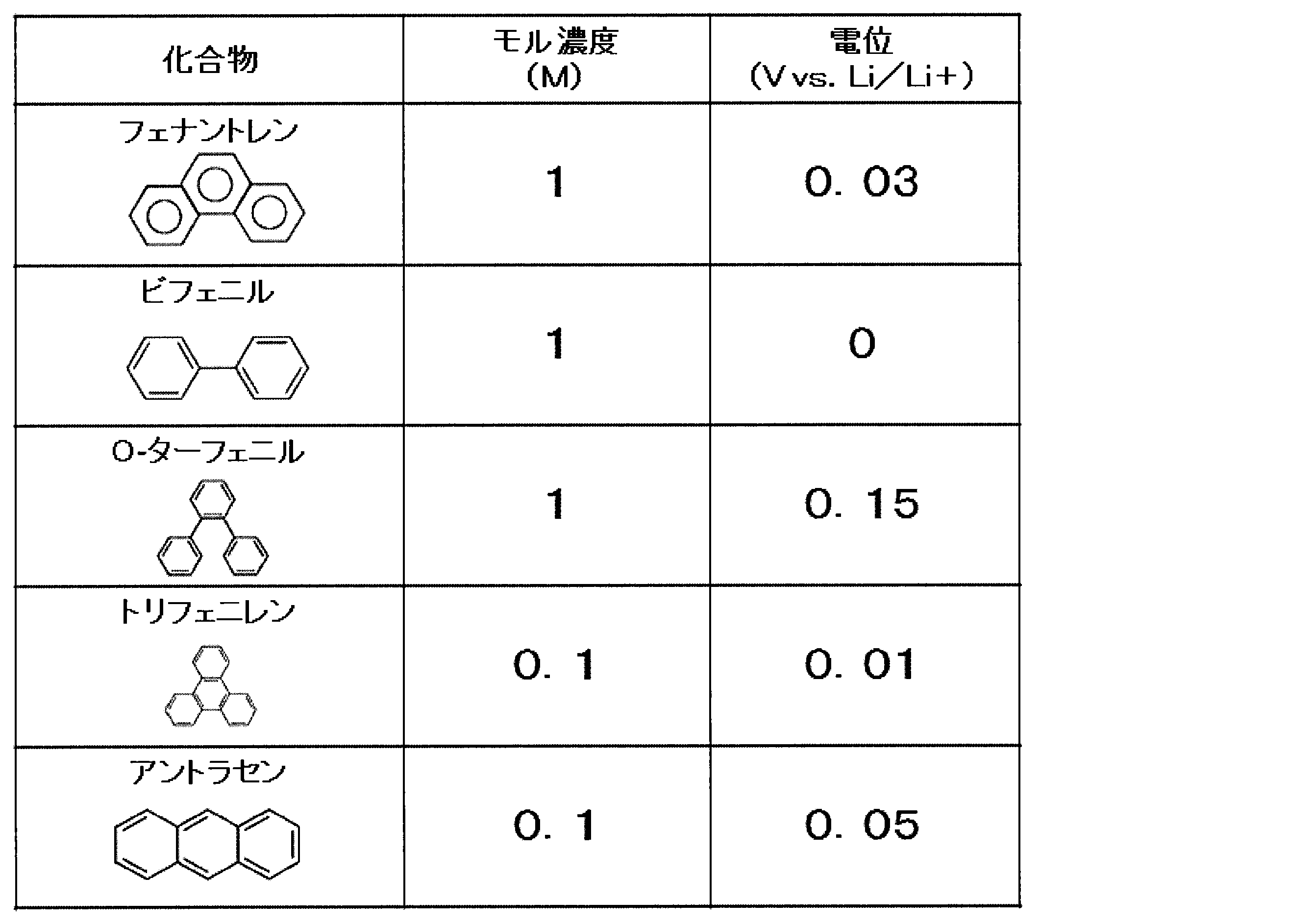
表3は、放電メディエータ122として用いられうる化合物の電位を示す。
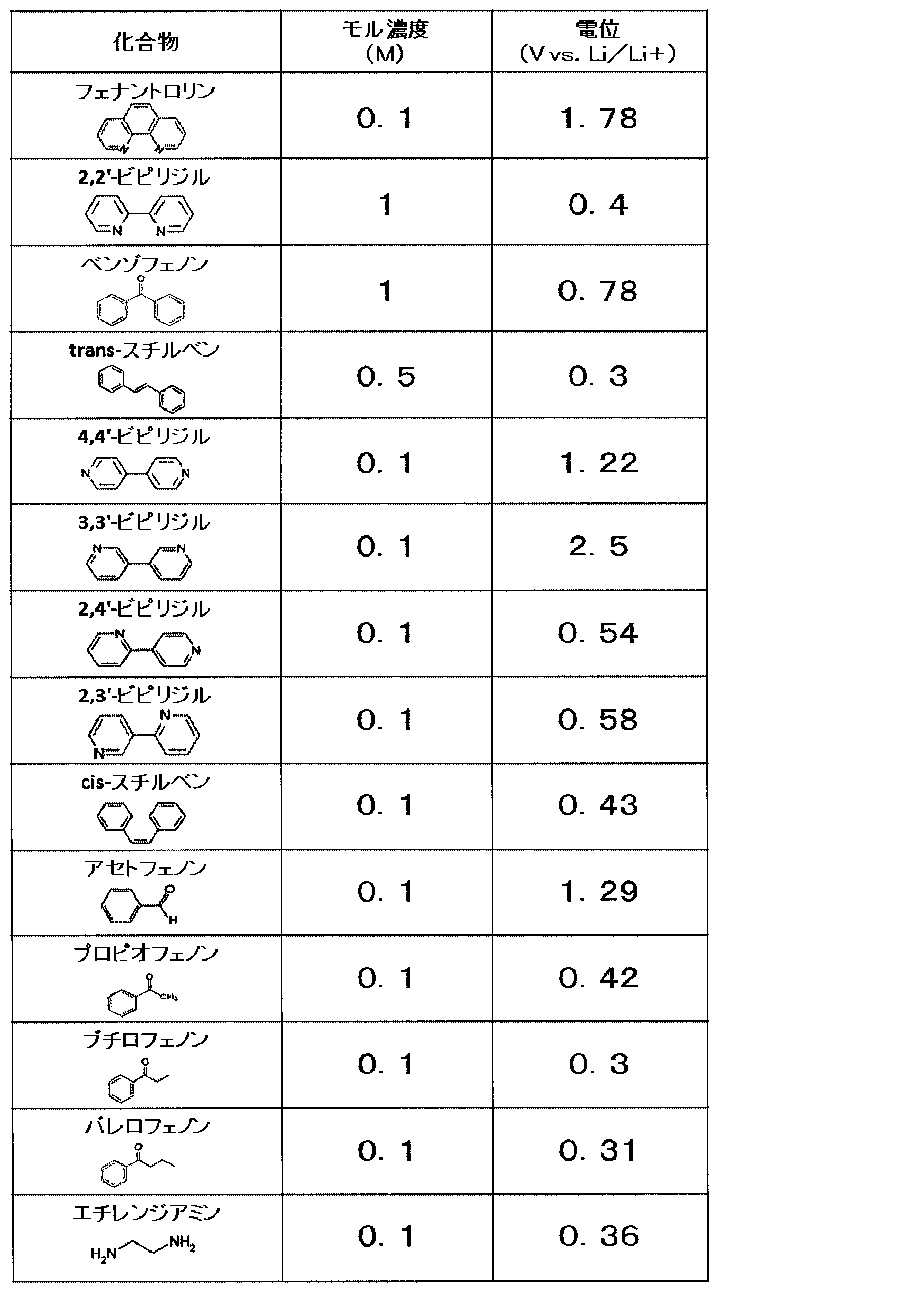
2×2cmの銅箔をポリプロピレン製微多孔性セパレータで包んだものの全体を、多量のリチウム金属箔で包む。これに、銅箔とリチウム金属にタブを取り付ける。その後、これに、ラミネート外装を取り付ける。これに、表2と表3とに示される各モル濃度(M)で化合物を溶かした2MeTHFを注液した後、ラミネート外装を熱融着して密閉する。以上により、化合物ごとに電位測定用セルが作製される。表2と表3は、この電位測定用セルを用いてリチウム金属基準で測定される電位(V vs. Li/Li+)を示す。なお、この測定ではエーテルとして2MeTHFが使用されうるが、他のエーテルも同様に使用可能である。
充電メディエータ121の場合は、C6Li中のLiを溶解させる能力がない。一方、放電メディエータ122の場合は、C6Li中のLiを溶解させる能力がある。この能力差は、これらのリチウム金属溶液の電位とC6Liの電位との差から、説明できる。すなわち、C6Liの電位(約0.2V vs. Li/Li+)より貴なものは、C6Li中のLiを溶解させる能力がある。一方で、C6Liの電位より卑なものは、C6Li中のLiを溶解させる能力がない。
したがって、C6Liより電位が卑なものを充電メディエータ121として使用できる。また、C6Liより電位が貴なものを放電メディエータ122として使用できる。
なお、化合物としては、第2活物質320との電位差が少ないほうが、充放電エネルギー効率により優れる。したがって、第2活物質320として黒鉛(C6Li)を用いる場合には、充電メディエータ121としては、フェナントレン、トリフェニレンまたはビフェニルを用いてもよい。また、放電メディエータ122としては、trans-スチルベン、ブチロフェノン、バレロフェノンまたはエチレンジアミンを用いてもよい。これにより、充放電エネルギー効率をより高めることができる。
なお、エーテルとしては、黒鉛にLiイオンとともに共挿入されないエーテルを用いてもよい。これにより、黒鉛にエーテルが共挿入されず、容量密度をより向上できる。
なお、第2活物質320として、固体の活物質が用いられてもよい。固体の活物質は、例えば、粉末状の活物質であってもよい。第2活物質320を加工無しの粉末状態でタンクに充填する場合には、製造を簡便化でき、かつ、製造コストを低減できる。
また、第2活物質320として、ペレット状の活物質が用いられてもよい。ペレット状の活物質は、例えば、粉末をペレット成型した状態の活物質であってもよい。第2活物質320をペレット状でタンクに充填する場合には、製造を簡便化でき、かつ、製造コストを低減できる。
また、第2活物質320として、公知のバインダーによりペレット状に固められた活物質が用いられてもよい。バインダーは、例えば、ポリフッ化ビニリデン、ポリプロピレン、ポリエチレン、ポリイミド、などであってもよい。
なお、第2活物質320は、第2液体120に不溶性の物質であってもよい。これにより、第2液体120とともに充電メディエータ121と放電メディエータ122とは循環させるが、第2活物質320は循環させない構成のフロー電池を実現できる。
なお、実施形態3におけるフロー電池3000においては、第2電極220は負極であり、かつ、第1電極210は正極であってもよい。
なお、第1電極210側として、相対的に電位の低い電極構造を用いれば、第2電極220側は、正極にもなりうる。
すなわち、第2電極220は正極であり、かつ、第1電極210は負極であってもよい。
なお、実施形態3におけるフロー電池3000においては、例えば、第2液体120が第2電極220に接触することにより、充電メディエータ121と放電メディエータ122とは、第2電極220により、酸化または還元される。すなわち、例えば、第2液体120が第2活物質320に接触することにより、第2活物質320による放電メディエータ122の還元反応が生じる、または、第2活物質320による充電メディエータ121の酸化反応が生じる。
第2電極220は、充電メディエータ121と放電メディエータ122の反応場として作用する表面を有する電極であってもよい。
この場合、第2電極220として、第2液体120に対して安定な材料が用いられうる。第2液体120に対して安定な材料は、第2液体120に不溶性である材料であってもよい。さらに、第2電極220として、電極反応である電気化学反応に対して安定な材料が用いられうる。例えば、第2電極220として、金属、カーボン、などが用いられうる。金属は、例えば、ステンレス鋼、鉄、銅、ニッケル、などであってもよい。
第2電極220は、その表面積を増大させた構造を有するものであってもよい。表面積を増大させた構造を有するものは、例えば、メッシュ、不織布、表面粗化処理板、焼結多孔体、などであってもよい。これによれば、第2電極220の比表面積が大きくなる。これにより、充電メディエータ121と放電メディエータ122の酸化反応または還元反応を、より進行し易くできる。
なお、実施形態3におけるフロー電池3000は、第2循環機構520をさらに備えてもよい。
第2循環機構520は、第2電極220と第2活物質320との間で、第2液体120を循環させる機構である。
以上の構成によれば、第2液体120とともに充電メディエータ121および放電メディエータ122を、第2電極220と第2活物質320との間で、循環させることができる。これにより、各材料間の酸化反応および還元反応を、より効率的に、行うことができる。
第2循環機構520は、例えば、配管、タンク、ポンプ、バルブ、などを備える機構であってもよい。
第2循環機構520の具体的な一例としては、後述する実施形態4の構成などが挙げられる。
<充放電プロセスの説明>
実施形態3におけるフロー電池3000の充放電プロセスが、以下に、説明される。
実施形態3におけるフロー電池3000の充放電プロセスが、以下に、説明される。
なお、具体的に、下記の構成である動作例が例示されながら、充放電プロセスが説明される。
本動作例では、第1電極210は、正極であり、カーボンブラックである。
また、本動作例では、第1液体110は、第1電極メディエータ111が溶解したエーテル溶液である。
また、本動作例では、第1電極メディエータ111は、上述された実施形態1のベンゼン誘導体(以下、dialkoxybenzene:DABと表記される)である。
また、本動作例では、第1活物質310は、リン酸鉄リチウム(LiCoO2)である。
また、本動作例では、第2電極220は、負極であり、ステンレス鋼である。
また、本動作例では、第2液体120は、充電メディエータ121と放電メディエータ122とが溶解したエーテル溶液である。
また、本動作例では、第2電極220側の充電メディエータ121は、1種の化合物(以下、ChMdと表記される)である。
また、本動作例では、第2電極220側の放電メディエータ122は、1種の化合物(以下、DchMdと表記される)である。
また、本動作例では、第2活物質320は、黒鉛(C6Li)である。
また、本動作例では、隔離部400は、リチウムイオン伝導性の固体電解質膜である。
[充電プロセスの説明]
まず、充電反応が、説明される。
まず、充電反応が、説明される。
第1電極210と第2電極220との間に、電圧が印加されることにより、充電が行われる。
(負極側の反応)
電圧の印加により、負極である第2電極220にフロー電池の外部から電子が供給される。これにより、第2電極220上では、充電メディエータ121と放電メディエータ122との還元反応が起こる。
電圧の印加により、負極である第2電極220にフロー電池の外部から電子が供給される。これにより、第2電極220上では、充電メディエータ121と放電メディエータ122との還元反応が起こる。
例えば、本動作例では、下記の反応が生じる。
ChMd + Li+ + e- → ChMd・Li
DchMd + Li+ + e- → DchMd・Li
ChMd + Li+ + e- → ChMd・Li
DchMd + Li+ + e- → DchMd・Li
第2循環機構520により、第2電極220により還元された充電メディエータ121が、第2活物質320が設けられた場所まで、移動させられる。すなわち、第2循環機構520により、第2電極220により還元された充電メディエータ121が、第2活物質320が設けられた場所まで、供給される。
このとき、第2電極220上において還元された充電メディエータ121は第2活物質320により酸化される。すなわち、第2活物質320は、充電メディエータ121によって、還元される。これにより、第2活物質320はリチウムを吸蔵して、C6Liとなる。
例えば、本動作例では、下記の反応が生じる。
6C + ChMd・Li → C6Li + ChMd
6C + ChMd・Li → C6Li + ChMd
第2循環機構520により、第2活物質320により酸化された充電メディエータ121が、第2電極220が設けられた場所まで、移動させられる。すなわち、第2循環機構520により、第2活物質320により酸化された充電メディエータ121が、第2電極220が設けられた場所まで、供給される。
以上のように、充電メディエータ121は、循環を含めたトータル反応で見ると、変化していない。
一方で、第2電極220と離れた場所に位置する第2活物質320、充電状態となる。
(正極側の反応)
電圧の印加により、正極である第1電極210では、第1電極メディエータ111の酸化反応が起こる。すなわち、第1電極210の表面において、第1電極メディエータ111が酸化される。これにより、第1電極210からフロー電池の外部に電子が放出される。
電圧の印加により、正極である第1電極210では、第1電極メディエータ111の酸化反応が起こる。すなわち、第1電極210の表面において、第1電極メディエータ111が酸化される。これにより、第1電極210からフロー電池の外部に電子が放出される。
例えば、本動作例では、下記の反応が生じる。
DAB → DAB+ + e-
DAB → DAB+ + e-
第1循環機構510により、第1電極210により酸化された第1電極メディエータ111が、第1活物質310が設けられた場所まで、移動させられる。すなわち、第1循環機構510により、第1電極210により酸化された第1電極メディエータ111が、第1活物質310が設けられた場所まで、供給される。
このとき、第1電極210上において酸化された第1電極メディエータ111は、第1活物質310により還元される。すなわち、第1活物質310は、第1電極メディエータ111によって、酸化される。これにより、第1活物質310はリチウムを放出する。
例えば、本動作例では、下記の反応が生じる。
LiCoO2 + DAB+ → CoO2 + Li+ + DAB+
LiCoO2 + DAB+ → CoO2 + Li+ + DAB+
第1循環機構510により、第1活物質310により還元された第1電極メディエータ111が、第1電極210が設けられた場所まで、移動させられる。すなわち、第1循環機構510により、第1活物質310により還元された第1電極メディエータ111が、第1電極210が設けられた場所まで、供給される。
このとき、第1電極210の表面において、第1電極メディエータ111が酸化される。
例えば、本動作例では、下記の反応が生じる。
DAB → DAB+ + e-
DAB → DAB+ + e-
なお、発生したリチウムイオン(Li+)の一部は、隔離部400を通じて、第2電極220側に移動しうる。
以上のように、第1電極メディエータ111は、循環を含めたトータル反応で見ると、変化していない。
一方で、第1電極210と離れた場所に位置する第1活物質310が、充電状態となる。
以上のように、第1電極210側においては、DAB+が第1電極側充電メディエータとして充電メディエータの役割を果たす。
完全充電状態では、第1液体110にはDAB+が存在し、第1活物質310はLiCoO2となる。このとき、充電電位は、DAB+への酸化電位で決定される。
以上の充電反応は、第1活物質310が完全充電状態となる、または、第2活物質320が完全充電状態となる、のどちらかに到達するまで、進行しうる。
[放電プロセスの説明]
次に、満充電からの放電反応が、説明される。
次に、満充電からの放電反応が、説明される。
満充電では、第1活物質310と第2活物質320とは、充電状態となっている。
放電反応では、第1電極210と第2電極220との間から、電力が取り出される。
(負極側の反応)
電池の放電により、負極である第2電極220上では、充電メディエータ121と放電メディエータ122との酸化反応が起こる。これにより、第2電極220からフロー電池の外部に電子が放出される。
電池の放電により、負極である第2電極220上では、充電メディエータ121と放電メディエータ122との酸化反応が起こる。これにより、第2電極220からフロー電池の外部に電子が放出される。
例えば、本動作例では、下記の反応が生じる。
DchMd・Li → DchMd + Li+ + e-
ChMd・Li → ChMd + Li+ + e-
DchMd・Li → DchMd + Li+ + e-
ChMd・Li → ChMd + Li+ + e-
第2循環機構520により、第2電極220により酸化された放電メディエータ122が、第2活物質320が設けられた場所まで、移動させられる。すなわち、第2循環機構520により、第2電極220により酸化された放電メディエータ122が、第2活物質320が設けられた場所まで、供給される。
このとき、第2電極220上において酸化された放電メディエータ122は第2活物質320により還元される。すなわち、第2活物質320は、放電メディエータ122によって、酸化される。これにより、第2活物質320はリチウムを放出する。
例えば、本動作例では、下記の反応が生じる。
C6Li + DchMd → 6C + DchMd・Li
C6Li + DchMd → 6C + DchMd・Li
第2循環機構520により、第2活物質320により還元された放電メディエータ122が、第2電極220が設けられた場所まで、移動させられる。すなわち、第2循環機構520により、第2活物質320により還元された放電メディエータ122が、第2電極220が設けられた場所まで、供給される。
以上のように、放電メディエータ122は、循環を含めたトータル反応で見ると、変化していない。
一方で、第2電極220と離れた場所に位置する第2活物質320が、放電状態となる。
(正極側の反応)
電池の放電により、正極である第1電極210にフロー電池の外部から電子が供給される。これにより、第1電極210上では、第1電極メディエータ111の還元反応が起こる。すなわち、第1電極210の表面において、第1電極メディエータ111が還元される。
電池の放電により、正極である第1電極210にフロー電池の外部から電子が供給される。これにより、第1電極210上では、第1電極メディエータ111の還元反応が起こる。すなわち、第1電極210の表面において、第1電極メディエータ111が還元される。
例えば、本動作例では、下記の反応が生じる。
DAB+ + e- → DAB
DAB+ + e- → DAB
第1循環機構510により、第1電極210により還元された第1電極メディエータ111が、第1活物質310が設けられた場所まで、移動させられる。すなわち、第1循環機構510により、第1電極210により還元された第1電極メディエータ111が、第1活物質310が設けられた場所まで、供給される。
このとき、第1電極210上において還元された第1電極メディエータ111は、第1活物質310により、酸化される。すなわち、第1活物質310は、第1電極メディエータ111により、還元される。これにより、第1活物質310は、リチウムを吸蔵する。
例えば、本動作例では、下記の反応が生じる。
CoO2 + Li+ + DAB → LiCoO2 + DAB+
CoO2 + Li+ + DAB → LiCoO2 + DAB+
第1循環機構510により、第1活物質310により酸化された第1電極メディエータ111が、第1電極210が設けられた場所まで、移動させられる。すなわち、第1循環機構510により、第1活物質310により酸化された第1電極メディエータ111が、第1電極210が設けられた場所まで、供給される。
このとき、第1電極210の表面において、第1電極メディエータ111が還元される。
例えば、本動作例では、下記の反応が生じる。
DAB+ + e- → DAB
DAB+ + e- → DAB
なお、リチウムイオン(Li+)の一部は、隔離部400を通じて、第2電極220側から供給されうる。
以上のように、第1電極メディエータ111は、循環を含めたトータル反応で見ると、変化していない。
一方で、第1電極210と離れた場所に位置する第1活物質310が、放電状態となる。
以上のように、第1電極210側においては、DABが第1電極側放電メディエータとして放電メディエータの役割を果たす。
完全放電状態では、第1液体110にはDABが存在し、第1活物質310はLiCoO2となる。このとき、放電電位は、DABへの還元電位で決定される。
以上の放電反応は、第1活物質310が完全放電状態となる、または、第2活物質320が完全放電状態となる、のどちらかに到達するまで、進行しうる。
<エネルギー密度の推算>
実施形態3におけるフロー電池3000のエネルギー密度の推算結果が、以下に、説明される。
実施形態3におけるフロー電池3000のエネルギー密度の推算結果が、以下に、説明される。
表4は、実施形態3におけるフロー電池3000のエネルギー密度の推算結果を示す。
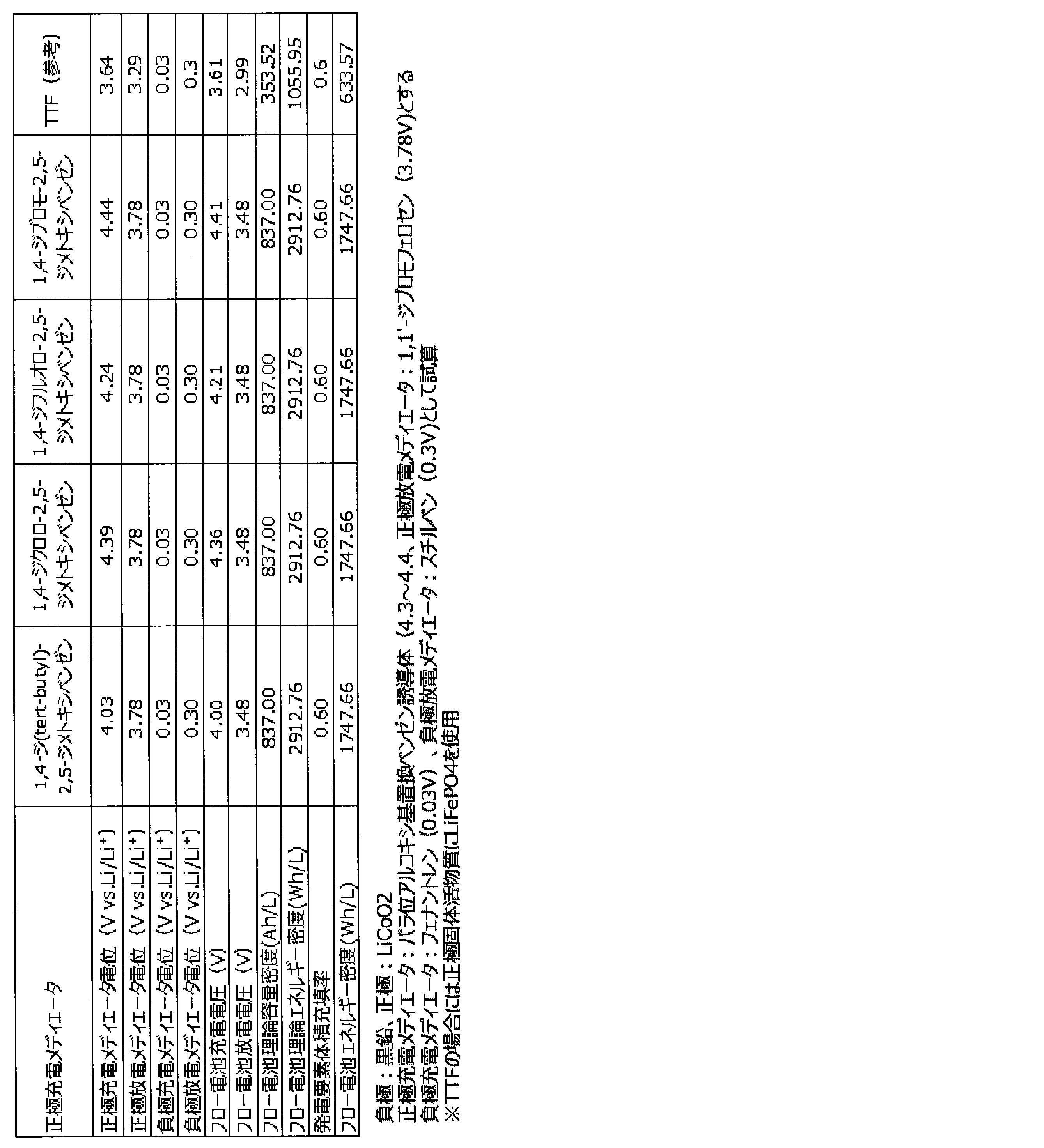
表4は、上述の表1に示される各ベンゼン誘導体を第1電極メディエータ111の充電メディエータとして用い、一段階酸化還元反応を示す正極充電メディエータの場合は正極放電メディエータとして2,2’-ビチオフェンなどを用いた場合で、かつ、実施形態3におけるフロー電池3000の上述の動作例の条件で、かつ、充電メディエータ121がフェナントレンであり、かつ、放電メディエータ122がtrans-スチルベンである場合のエネルギー密度の推算結果を示す。なお、表4において、発電要素体積充填率は、比率を表す。例えば、発電要素体積充填率が0.60とは60%であることを意味する。
また、表4において、第1電極メディエータ111、すなわち、正極充電メディエータとしてテトラチアフルバレンを用いる計算例においては、正極固体活物質はLiFePO4であり、かつ、1,1’-ジブロモフェロセンは用いていない。テトラチアフルバレン(TTF)は正極放電メディエータとしても機能するためである。
表4に示される通り、1,4-ジ(tert-ブチル)-2,5-ジメトキシベンゼンなど充電メディエータとして、放電メディエータとして1,1’-ジブロモフェロセンのようなシクロペンタジエニル化合物を第1電極メディエータ111として用いた場合にはエネルギー密度が1747Wh/L程度のフロー電池を実現できる。
これらに対して、バナジウムを利用する従来のフロー電池の理論エネルギー密度は、38Wh/L程度である。この結果から、従来のフロー電池と比較して、本開示のフロー電池の理論エネルギー密度は、格段に高いことがわかる。
また、表4に示される通り、テトラチアフルバレンを第1電極メディエータ111として用いる場合には、正極固体活物質としてLiFePO4を用いるためにエネルギー密度が633Wh/L程度のフロー電池となる。この結果から、テトラチアフルバレンまたはその誘導体などを用いる場合と比較して、ベンゼン誘導体を用いたフロー電池の理論エネルギー密度は、より高いことがわかる。
(実施形態4)
以下、実施形態4が説明される。なお、上述の実施形態1から3のいずれかと重複する説明は、適宜、省略される。
以下、実施形態4が説明される。なお、上述の実施形態1から3のいずれかと重複する説明は、適宜、省略される。
図4は、実施形態4におけるフロー電池4000の概略構成を例示的に示す模式図である。
実施形態4におけるフロー電池4000は、上述の実施形態3におけるフロー電池3000の構成に加えて、下記の構成を備える。
まず、実施形態4におけるフロー電池4000は、上述の実施形態2において示された第1循環機構510の構成を備える。
さらに、実施形態4におけるフロー電池4000は、上述の実施形態2において示された、電気化学反応部600と、正極端子211と、負極端子221と、を備える。
さらに、実施形態4におけるフロー電池4000は、第2循環機構520を備える。
第2循環機構520は、第2収容部521を備える。
第2活物質320と第2液体120とは、第2収容部521に、収容される。
第2循環機構520は、第2電極220と第2収容部521との間で、第2液体120を循環させる。
第2収容部521において第2活物質320と第2液体120とが接触することにより、第2活物質320による充電メディエータ121の酸化反応と、第2活物質320による放電メディエータ122の還元反応と、のうちの少なくとも一方が行われる。
以上の構成によれば、第2収容部521において、第2液体120と第2活物質320とを、接触させることができる。これにより、例えば、第2液体120と第2活物質320との接触面積を、より大きくできる。また、第2液体120と第2活物質320との接触時間を、より長くできる。このため、第2活物質320による充電メディエータ121の酸化反応と、第2活物質320による放電メディエータ122の還元反応を、より効率的に、行うことができる。
なお、実施形態4においては、第2収容部521は、例えば、タンクであってもよい。
また、第2収容部521は、例えば、充填された第2活物質320の隙間に、充電メディエータ121と放電メディエータ122とが溶解した第2液体120を、収容していてもよい。
また、図4に示されるように、実施形態4におけるフロー電池4000においては、第2循環機構520は、配管523と、配管524と、ポンプ525と、を備えてもよい。
配管524の一端は、正極室610と負極室620とのうち、第2電極220が配置される方に、接続される。図4では、配管524の一端は、負極室620に、接続される。
配管524の別の一端は、第2収容部521の第2液体120の流入口側に、接続される。
配管523の一端は、第2収容部521の第2液体120の流出口側に、接続される。
配管523の別の一端は、正極室610と負極室620とのうち、第2電極220が配置される方に、接続される。図4では、配管523の別の一端は、負極室620に、接続される。
ポンプ525は、例えば、配管524に設けられる。または、ポンプ525は、配管523に設けられてもよい。
なお、実施形態4におけるフロー電池4000においては、第2循環機構520は、第2透過抑制部522を備えてもよい。
第2透過抑制部522は、第2活物質320の透過を抑制する。
第2透過抑制部522は、第2液体120が第2収容部521から第2電極220に流出する経路に、設けられる。図4では、第2透過抑制部522は、配管523に、設けられる。
以上の構成によれば、第2活物質320が第2収容部521以外(例えば、第2電極220側)へ流出することを抑制できる。すなわち、第2活物質320は、第2収容部521に留まる。これにより、第2活物質320そのものは循環させない構成のフロー電池を実現できる。このため、第2循環機構520の部材の内部の第2活物質320による目詰まりを防止できる。また、第2活物質320が第2電極220側に流出することによる抵抗損失の発生を防止できる。第2循環機構520の部材は、例えば、配管であってもよい。
第2透過抑制部522は、例えば、第2収容部521と配管523との接合部に、設けられてもよい。
第2透過抑制部522は、例えば、第2活物質320を濾過するフィルターであってもよい。このとき、フィルターは、第2活物質320の粒子の最小粒径より小さい孔を有する部材であってもよい。フィルターの材料としては、第2活物質320および第2液体120などと反応しない材料が用いられうる。フィルターは、例えば、ガラス繊維濾紙、ポリプロピレン不織布、ポリエチレン不織布、金属リチウムと反応しない金属メッシュ、など、であってもよい。
以上の構成によれば、第2収容部521の内部において、第2液体120の流動とともに、第2活物質320の流動が生じても、第2活物質320が第2収容部521から流出することを防止できる。
図4では、第2収容部521に収容されている第2液体120は、第2透過抑制部522と配管523とを通過して、負極室620に、供給される。
これにより、第2液体120に溶解している充電メディエータ121と放電メディエータ122とは、第2電極220により、酸化または還元される。
その後、酸化または還元された充電メディエータ121と放電メディエータ122とが溶解した第2液体120は、配管524とポンプ525とを通過して、第2収容部521に、供給される。
これにより、第2液体120に溶解している充電メディエータ121と放電メディエータ122に対して、第2活物質320による充電メディエータ121の酸化反応と、第2活物質320による放電メディエータ122の還元反応と、のうちの少なくとも一方が行われる。
なお、第2液体120の循環の制御は、例えば、ポンプ525により行われてもよい。すなわち、ポンプ525により、適宜、第2液体120の供給の開始、または、供給の停止、または、供給量などの調整、が行われる。
また、第2液体120の循環の制御は、ポンプ525以外の他の手段により、行われてもよい。他の手段は、例えば、バルブなどであってもよい。
なお、図4においては、一例として、第1電極210は正極であり、かつ、第2電極220は負極である。
ここで、第1電極210側として、相対的に電位の低い電極構造を用いれば、第2電極220側は、正極にもなりうる。
すなわち、第2電極220は正極であり、かつ、第1電極210は負極であってもよい。
なお、本開示のベンゼン誘導体であれば、従来のテトラチアフルバレン誘導体などをメディエータとして、LiFePO4を正極固体活物質として用いたフロー電池と比較して、より高い放電電位とより高いエネルギー密度とを有するフロー電池を実現できる。
なお、上述の実施形態1から4のそれぞれに記載の構成は、適宜、互いに、組み合わされてもよい。
次に、実施例を挙げて本開示に係るフロー電池をさらに具体的に説明するが、本開示はこれらの実施例により何ら限定されるものではない。
[実施例1~4]
1Mの電解質を溶媒に溶解させた電解液を準備した。電解質としては、LiBF4を用いた。溶媒としては、プロピレンカーボネート(PC)を用いた。当該電解液に表1に示される各ベンゼン誘導体をそれぞれの5mM溶解することで、表1に示される各ベンゼン誘導体に対応する電解液を得た。それぞれの電解液と対極と作用極と参照極とで、表1に示される各ベンゼン誘導体に対応する電位測定用セルを作製した。対極には、1x1cmのPt箔を用いた。作用極には、電気化学測定用グラッシーカーボン電極(φ6mm)を用いた。参照極には、銀線(Ag/Ag+)を用いた。それぞれの電位測定用セルを用いて、サイクリックボルタンメトリ(CV)測定を行った。結果を図5に示す。図5から、パラ位に結合したアルコキシ基の非共有電子対の存在による電子供与性の共役効果によりベンゼン誘導体のカチオンラジカルが安定化され可逆に充放電を行うことができることが確認された。
1Mの電解質を溶媒に溶解させた電解液を準備した。電解質としては、LiBF4を用いた。溶媒としては、プロピレンカーボネート(PC)を用いた。当該電解液に表1に示される各ベンゼン誘導体をそれぞれの5mM溶解することで、表1に示される各ベンゼン誘導体に対応する電解液を得た。それぞれの電解液と対極と作用極と参照極とで、表1に示される各ベンゼン誘導体に対応する電位測定用セルを作製した。対極には、1x1cmのPt箔を用いた。作用極には、電気化学測定用グラッシーカーボン電極(φ6mm)を用いた。参照極には、銀線(Ag/Ag+)を用いた。それぞれの電位測定用セルを用いて、サイクリックボルタンメトリ(CV)測定を行った。結果を図5に示す。図5から、パラ位に結合したアルコキシ基の非共有電子対の存在による電子供与性の共役効果によりベンゼン誘導体のカチオンラジカルが安定化され可逆に充放電を行うことができることが確認された。
[比較例1~5]
比較例1として、第1電極メディエータとして用いられる化合物を、1,3-ジメトキシベンゼンに変更した以外は、実施例1と同様にして、サイクリックボルタンメトリの測定を行った。結果を図6Aに示す。比較例2として、第1電極メディエータとして用いられる化合物を、1,4-ジメトキシベンゼンに変更した以外は、実施例1と同様にして、サイクリックボルタンメトリの測定を行った。結果を図6Bに示す。比較例3として、第1電極メディエータとして用いられる化合物を、1-ブロモ-2,5-ジメトキシベンゼンに変更した以外は、実施例1と同様にして、サイクリックボルタンメトリの測定を行った。結果を図6Cに示す。比較例4として、第1電極メディエータとして用いられる化合物を、1-ブロモ-2,4-ジメトキシベンゼンに変更した以外は、実施例1と同様にして、サイクリックボルタンメトリの測定を行った。結果を図6Dに示す。比較例5として、第1電極メディエータとして用いられる化合物を、1-ブロモ-3,4-ジメトキシベンゼンに変更した以外は、実施例1と同様にして、サイクリックボルタンメトリの測定を行った。結果を図6Eに示す。
比較例1として、第1電極メディエータとして用いられる化合物を、1,3-ジメトキシベンゼンに変更した以外は、実施例1と同様にして、サイクリックボルタンメトリの測定を行った。結果を図6Aに示す。比較例2として、第1電極メディエータとして用いられる化合物を、1,4-ジメトキシベンゼンに変更した以外は、実施例1と同様にして、サイクリックボルタンメトリの測定を行った。結果を図6Bに示す。比較例3として、第1電極メディエータとして用いられる化合物を、1-ブロモ-2,5-ジメトキシベンゼンに変更した以外は、実施例1と同様にして、サイクリックボルタンメトリの測定を行った。結果を図6Cに示す。比較例4として、第1電極メディエータとして用いられる化合物を、1-ブロモ-2,4-ジメトキシベンゼンに変更した以外は、実施例1と同様にして、サイクリックボルタンメトリの測定を行った。結果を図6Dに示す。比較例5として、第1電極メディエータとして用いられる化合物を、1-ブロモ-3,4-ジメトキシベンゼンに変更した以外は、実施例1と同様にして、サイクリックボルタンメトリの測定を行った。結果を図6Eに示す。
本開示のフロー電池は、例えば、蓄電デバイスまたは蓄電システムとして使用できる。
110 第1液体
111 第1電極メディエータ
120 第2液体
121 充電メディエータ
122 放電メディエータ
210 第1電極
211 正極端子
220 第2電極
221 負極端子
310 第1活物質
320 第2活物質
400 隔離部
510 第1循環機構
511 第1収容部
512 第1透過抑制部
513、514、523、524 配管
515、525 ポンプ
520 第2循環機構
521 第2収容部
522 第2透過抑制部
600 電気化学反応部
610 正極室
620 負極室
1000、2000、3000、4000 フロー電池
111 第1電極メディエータ
120 第2液体
121 充電メディエータ
122 放電メディエータ
210 第1電極
211 正極端子
220 第2電極
221 負極端子
310 第1活物質
320 第2活物質
400 隔離部
510 第1循環機構
511 第1収容部
512 第1透過抑制部
513、514、523、524 配管
515、525 ポンプ
520 第2循環機構
521 第2収容部
522 第2透過抑制部
600 電気化学反応部
610 正極室
620 負極室
1000、2000、3000、4000 フロー電池
Claims (19)
- 第1電極メディエータを含む第1液体と、
第1電極と、
第1活物質と、
前記第1電極と前記第1活物質との間で前記第1液体を循環させる第1循環機構とを備え、
前記第1電極メディエータは、パラ位に少なくとも一組のアルコキシ基を有するベンゼン誘導体を含む、フロー電池。 - 前記ベンゼン誘導体は、アルコキシ基を有するパラ位以外の位置に水素原子以外の原子または置換基を少なくとも一つ有する、請求項1に記載のフロー電池。
- 前記ベンゼン誘導体は、下記一般式(1)で示されるベンゼン誘導体である、請求項1または2に記載のフロー電池。
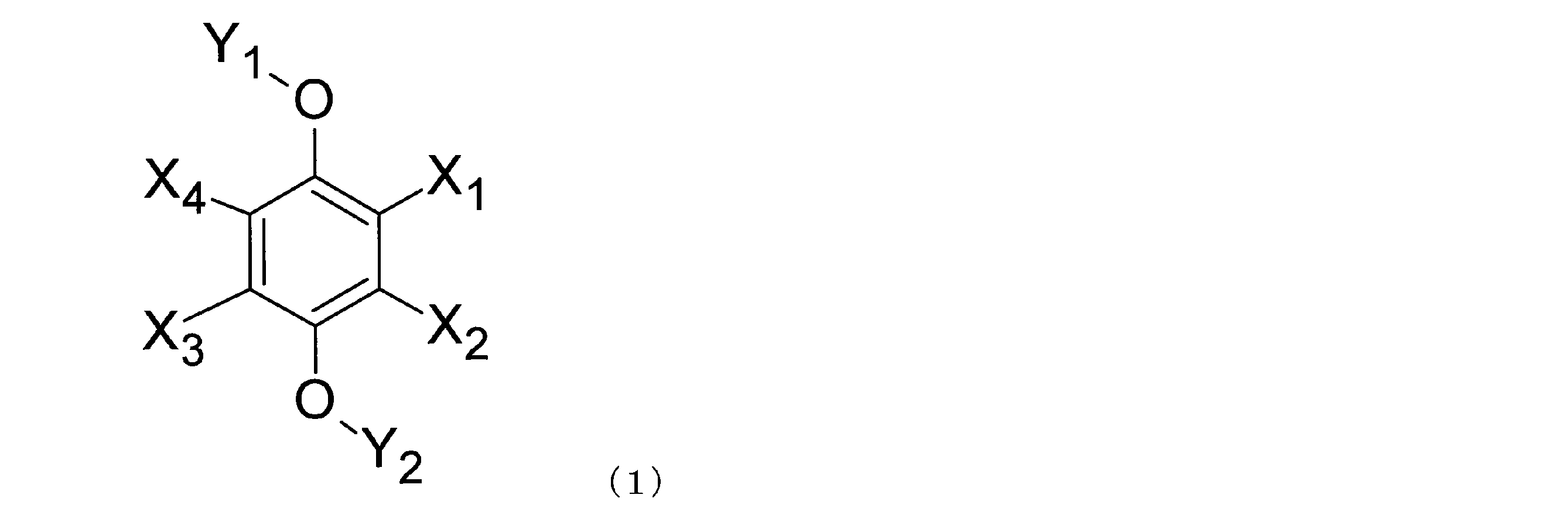
- 前記ベンゼン誘導体は、下記一般式(2)で示されるベンゼン誘導体である、請求項1から3のいずれか1項に記載のフロー電池。
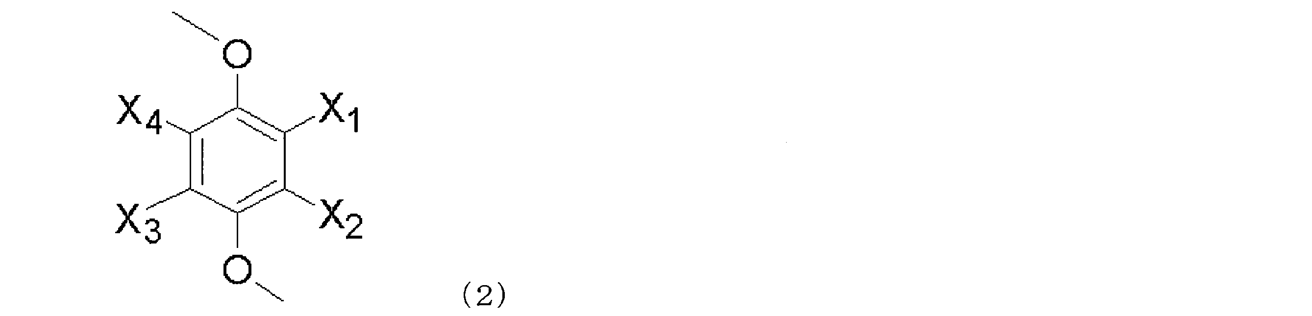
- 前記ベンゼン誘導体は、下記一般式(3)で示されるベンゼン誘導体である、請求項1から3のいずれか1項に記載のフロー電池。
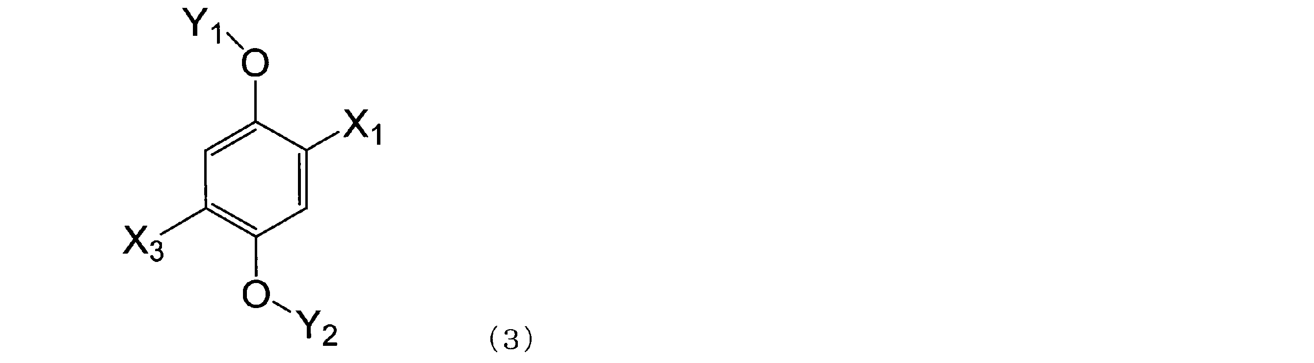
- 前記ベンゼン誘導体は、下記一般式(4)で示されるベンゼン誘導体である、請求項1から3のいずれか1項に記載のフロー電池。
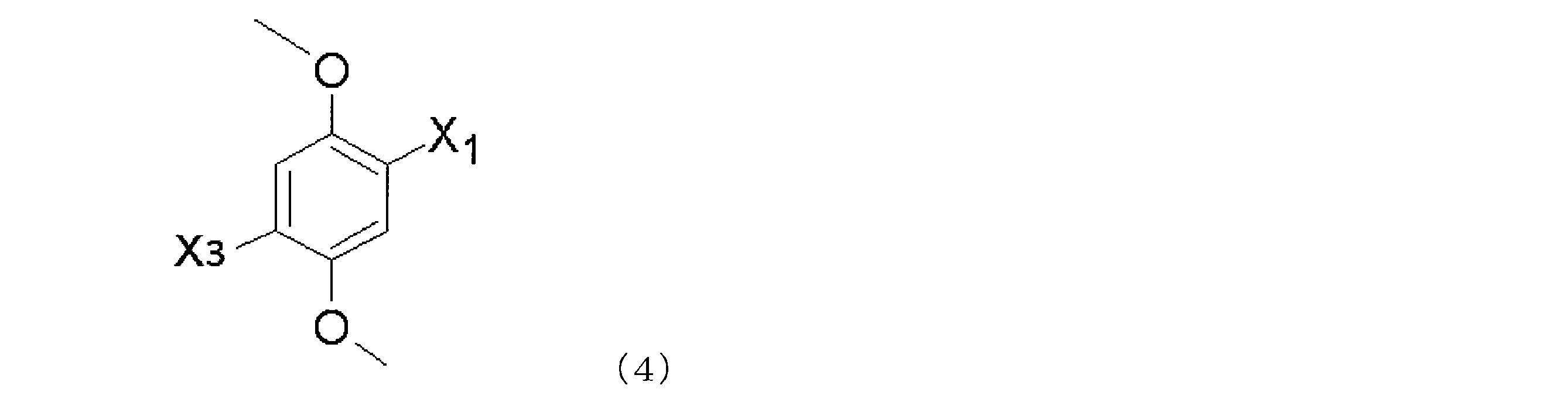
- 前記ベンゼン誘導体は、1,4-ジ(tert-ブチル)-2,5-ジメトキシベンゼン、1,4-ジクロロ-2,5-ジメトキシベンゼン、1,4-ジフルオロ-2,5-ジメトキシベンゼン、および1,4-ジブロモ-2,5-ジメトキシベンゼンからなる群より選ばれる少なくとも1種である、請求項1から6のいずれか1項に記載のフロー電池。
- 前記ベンゼン誘導体は、第1酸化還元電位と第2酸化還元電位とを有し、
前記第1活物質の平衡電位は、前記第1酸化還元電位より高く、かつ、前記第2酸化還元電位より低い、請求項1から7のいずれか1項に記載のフロー電池。 - 前記第1液体は、第1電極側放電メディエータを、さらに含み、
前記ベンゼン誘導体は、酸化電位を有し、
前記第1活物質の平衡電位は、前記ベンゼン誘導体の前記酸化電位より低く、
前記第1活物質の平衡電位は、前記第1電極側放電メディエータの平衡電位より高い、請求項1から8のいずれか1項に記載のフロー電池。 - 前記第1循環機構は、第1収容部を備え、
前記第1活物質と前記第1液体とは、前記第1収容部に収容され、
前記第1循環機構は、前記第1電極と前記第1収容部との間で、前記第1液体を循環させ、
前記第1収容部において前記第1活物質と前記第1液体とが接触することにより、前記第1活物質と前記第1電極メディエータと間の酸化反応と還元反応とのうちの少なくとも一方が行われる、請求項1から9のいずれか1項に記載のフロー電池。 - 前記第1循環機構は、前記第1活物質の透過を抑制する第1透過抑制部を備え、
前記第1透過抑制部は、前記第1液体が前記第1収容部から前記第1電極に流出する経路に、設けられる、請求項1から10のいずれか1項に記載のフロー電池。 - 充電メディエータと放電メディエータとを含む第2液体と、
前記第2液体に浸漬される第2電極と、
前記第2液体に浸漬される第2活物質と、
前記第1電極および前記第1液体と、前記第2電極および前記第2液体との間を隔離する隔離部と、をさらに備え、
前記充電メディエータの平衡電位は、前記第2活物質の平衡電位より低く、
前記放電メディエータの平衡電位は、前記第2活物質の平衡電位より高い、請求項1から11のいずれか1項に記載のフロー電池。 - 前記第2液体には、リチウムが溶解され、
前記第2活物質は、前記リチウムを吸蔵および放出する性質を有する物質であり、
充電時においては、前記充電メディエータは前記第2電極上において還元され、かつ、前記第2電極上において還元された前記充電メディエータは前記第2活物質により酸化されるとともに前記第2活物質は前記リチウムを吸蔵し、
放電時においては、前記リチウムを吸蔵した前記第2活物質は前記放電メディエータを還元するとともに前記第2活物質は前記リチウムを放出し、かつ、前記第2活物質により還元された前記放電メディエータは前記第2電極上において酸化される、請求項12に記載のフロー電池。 - 前記充電時においては、前記放電メディエータは前記第2電極上において還元され、
前記放電時においては、前記充電メディエータは前記第2電極上において酸化される、請求項12に記載のフロー電池。 - 前記充電メディエータと前記放電メディエータとは、縮合芳香族化合物であり、
前記縮合芳香族化合物が溶解した前記第2液体は、リチウムの溶媒和電子を放出させ、前記リチウムをカチオンとして溶解する性質を有する、請求項12から14のいずれか1項に記載のフロー電池。 - 前記充電メディエータは、フェナントレン、ビフェニル、o-ターフェニル、トリフェニレン、およびアントラセンからなる群より選ばれる少なくとも1種である、請求項12から15のいずれか1項に記載のフロー電池。
- 前記放電メディエータは、フェナントロリン、2,2’-ビピリジル、ベンゾフェノン、trans-スチルベン、4,4’-ビピリジル、3,3’-ビピリジル、2,4’-ビピリジル、2,3’-ビピリジル、cis-スチルベン、アセトフェノン、プロピオフェノン、ブチロフェノン、バレロフェノン、およびエチレンジアミンからなる群より選ばれる少なくとも1種である、請求項12から16のいずれか1項に記載のフロー電池。
- 第2収容部を備える第2循環機構をさらに備え、
前記第2活物質と前記第2液体とは、前記第2収容部に、収容され、
前記第2循環機構は、前記第2電極と前記第2収容部との間で、前記第2液体を循環させ、
前記第2収容部において前記第2活物質と前記第2液体とが接触することにより、前記第2活物質による前記充電メディエータの酸化反応と、前記第2活物質による前記放電メディエータの還元反応と、のうちの少なくとも一方が行われる、請求項12から17のいずれか1項に記載のフロー電池。 - 前記第2循環機構は、前記第2活物質の透過を抑制する第2透過抑制部を備え、
前記第2透過抑制部は、前記第2液体が前記第2収容部から前記第2電極に流出する経路に、設けられる、請求項12から18のいずれか1項に記載のフロー電池。
Priority Applications (4)
| Application Number | Priority Date | Filing Date | Title |
|---|---|---|---|
| EP19759484.9A EP3780208A4 (en) | 2018-04-06 | 2019-02-13 | CIRCULATING BATTERY |
| CN201980001182.5A CN110574202A (zh) | 2018-04-06 | 2019-02-13 | 液流电池 |
| JP2019529672A JP6846690B2 (ja) | 2018-04-06 | 2019-02-13 | フロー電池 |
| US16/550,172 US11094957B2 (en) | 2018-04-06 | 2019-08-23 | Flow battery |
Applications Claiming Priority (2)
| Application Number | Priority Date | Filing Date | Title |
|---|---|---|---|
| JP2018073868 | 2018-04-06 | ||
| JP2018-073868 | 2018-04-06 |
Related Child Applications (1)
| Application Number | Title | Priority Date | Filing Date |
|---|---|---|---|
| US16/550,172 Continuation US11094957B2 (en) | 2018-04-06 | 2019-08-23 | Flow battery |
Publications (1)
| Publication Number | Publication Date |
|---|---|
| WO2019193840A1 true WO2019193840A1 (ja) | 2019-10-10 |
Family
ID=68100742
Family Applications (1)
| Application Number | Title | Priority Date | Filing Date |
|---|---|---|---|
| PCT/JP2019/005064 Ceased WO2019193840A1 (ja) | 2018-04-06 | 2019-02-13 | フロー電池 |
Country Status (5)
| Country | Link |
|---|---|
| US (1) | US11094957B2 (ja) |
| EP (1) | EP3780208A4 (ja) |
| JP (1) | JP6846690B2 (ja) |
| CN (1) | CN110574202A (ja) |
| WO (1) | WO2019193840A1 (ja) |
Families Citing this family (1)
| Publication number | Priority date | Publication date | Assignee | Title |
|---|---|---|---|---|
| JPWO2020261792A1 (ja) * | 2019-06-27 | 2021-10-07 | パナソニックIpマネジメント株式会社 | レドックスフロー電池 |
Citations (3)
| Publication number | Priority date | Publication date | Assignee | Title |
|---|---|---|---|---|
| JP2014524124A (ja) | 2011-07-21 | 2014-09-18 | ナショナル ユニヴァーシティー オブ シンガポール | レドックスフロー電池システム |
| WO2016208123A1 (ja) | 2015-06-23 | 2016-12-29 | パナソニックIpマネジメント株式会社 | レドックスフロー電池 |
| WO2018016249A1 (ja) * | 2016-07-19 | 2018-01-25 | パナソニックIpマネジメント株式会社 | フロー電池 |
Family Cites Families (9)
| Publication number | Priority date | Publication date | Assignee | Title |
|---|---|---|---|---|
| US8367253B2 (en) * | 2006-02-02 | 2013-02-05 | U Chicago Argonne Llc | Lithium-ion batteries with intrinsic pulse overcharge protection |
| CN101577348B (zh) * | 2009-05-15 | 2011-03-23 | 中南大学 | 锂离子电池多重过充防护功能性电解液 |
| FR2975098B1 (fr) * | 2011-05-12 | 2014-02-07 | Centre Nat Rech Scient | Composes a groupement redox, leur utilisation comme additif d'electrolyte, composition d'electrolyte et systemes electrochimiques les contenant |
| US9966625B2 (en) * | 2012-02-28 | 2018-05-08 | Uchicago Argonne, Llc | Organic non-aqueous cation-based redox flow batteries |
| US9300000B2 (en) * | 2012-02-28 | 2016-03-29 | Uchicago Argonne, Llc | Organic non-aqueous cation-based redox flow batteries |
| US9812883B2 (en) * | 2014-02-18 | 2017-11-07 | Massachusetts Institute Of Technology | Materials for use with aqueous redox flow batteries and related methods and systems |
| FR3024343A1 (fr) * | 2014-07-29 | 2016-02-05 | Frederic Karakozian | Systeme de protection pour dispositif de communication mobile et procede d'installation de ce systeme de protection |
| US10811669B2 (en) * | 2015-02-17 | 2020-10-20 | Nec Corporation | Battery and method for manufacturing same |
| US10892525B2 (en) * | 2016-06-29 | 2021-01-12 | University Of Kentucky Research Foundation | Rechargeable batteries including high-voltage cathode and redox shuttle conferring overcharge protection |
-
2019
- 2019-02-13 JP JP2019529672A patent/JP6846690B2/ja not_active Expired - Fee Related
- 2019-02-13 CN CN201980001182.5A patent/CN110574202A/zh active Pending
- 2019-02-13 EP EP19759484.9A patent/EP3780208A4/en not_active Withdrawn
- 2019-02-13 WO PCT/JP2019/005064 patent/WO2019193840A1/ja not_active Ceased
- 2019-08-23 US US16/550,172 patent/US11094957B2/en not_active Expired - Fee Related
Patent Citations (3)
| Publication number | Priority date | Publication date | Assignee | Title |
|---|---|---|---|---|
| JP2014524124A (ja) | 2011-07-21 | 2014-09-18 | ナショナル ユニヴァーシティー オブ シンガポール | レドックスフロー電池システム |
| WO2016208123A1 (ja) | 2015-06-23 | 2016-12-29 | パナソニックIpマネジメント株式会社 | レドックスフロー電池 |
| WO2018016249A1 (ja) * | 2016-07-19 | 2018-01-25 | パナソニックIpマネジメント株式会社 | フロー電池 |
Non-Patent Citations (3)
| Title |
|---|
| HUANG ET AL.: "A subtractive approach to molecular engineering of dimethoxybenzene-based redox materials for nonaqueous flow batteries", JOURNAL OF MATERIALS CHEMISTRY A, vol. 3, no. 29, 1 January 2015 (2015-01-01), pages 14971 - 14976, XP055643042 * |
| See also references of EP3780208A4 * |
| ZHANG ET AL.: "Annulated Dialkoxybenzenes as Catholyte Materials for Non-aqueous Redox Flow Batteries. Achieving High Chemical Stability through Bicyclic Substitution", ADVANCED ENERGY MATERIALS, vol. 7, no. 21, November 2017 (2017-11-01), pages 1701272, XP055643044 * |
Also Published As
| Publication number | Publication date |
|---|---|
| EP3780208A4 (en) | 2021-06-16 |
| US11094957B2 (en) | 2021-08-17 |
| CN110574202A (zh) | 2019-12-13 |
| US20190379080A1 (en) | 2019-12-12 |
| EP3780208A1 (en) | 2021-02-17 |
| JPWO2019193840A1 (ja) | 2020-04-30 |
| JP6846690B2 (ja) | 2021-03-24 |
Similar Documents
| Publication | Publication Date | Title |
|---|---|---|
| US10873101B2 (en) | Flow battery | |
| US10529997B2 (en) | Redox flow battery including permeation preventer for retaining insoluble active material in electrolytic solution container | |
| US10547077B2 (en) | Flow battery | |
| US10797337B2 (en) | Flow battery | |
| CN116636038A (zh) | 锂二次电池 | |
| JP2017010865A (ja) | 二次電池 | |
| EP3416223B1 (en) | Flow battery | |
| US11211618B2 (en) | Flow battery that includes liquid containing mediator | |
| JP6846690B2 (ja) | フロー電池 | |
| US10658693B2 (en) | Flow battery | |
| JP2019003875A (ja) | フロー電池 | |
| JP2019021617A (ja) | フロー電池 | |
| WO2019230347A1 (ja) | フロー電池 | |
| US11264632B2 (en) | Flow battery | |
| JP7122698B2 (ja) | フロー電池 | |
| JP2019212616A (ja) | フロー電池 | |
| JP2020191157A (ja) | リチウム二次電池 | |
| JP2019021616A (ja) | フロー電池 | |
| JP2019021618A (ja) | フロー電池 |
Legal Events
| Date | Code | Title | Description |
|---|---|---|---|
| ENP | Entry into the national phase |
Ref document number: 2019529672 Country of ref document: JP Kind code of ref document: A |
|
| 121 | Ep: the epo has been informed by wipo that ep was designated in this application |
Ref document number: 19759484 Country of ref document: EP Kind code of ref document: A1 |
|
| NENP | Non-entry into the national phase |
Ref country code: DE |
|
| ENP | Entry into the national phase |
Ref document number: 2019759484 Country of ref document: EP Effective date: 20201106 |