WO2019194201A1 - 金属板、金属板の製造方法、金属板の成形品の製造方法および金属板の成形品 - Google Patents
金属板、金属板の製造方法、金属板の成形品の製造方法および金属板の成形品 Download PDFInfo
- Publication number
- WO2019194201A1 WO2019194201A1 PCT/JP2019/014693 JP2019014693W WO2019194201A1 WO 2019194201 A1 WO2019194201 A1 WO 2019194201A1 JP 2019014693 W JP2019014693 W JP 2019014693W WO 2019194201 A1 WO2019194201 A1 WO 2019194201A1
- Authority
- WO
- WIPO (PCT)
- Prior art keywords
- metal plate
- molded product
- less
- crystal grains
- plane
- Prior art date
- Legal status (The legal status is an assumption and is not a legal conclusion. Google has not performed a legal analysis and makes no representation as to the accuracy of the status listed.)
- Ceased
Links
Images


Classifications
-
- C—CHEMISTRY; METALLURGY
- C22—METALLURGY; FERROUS OR NON-FERROUS ALLOYS; TREATMENT OF ALLOYS OR NON-FERROUS METALS
- C22C—ALLOYS
- C22C38/00—Ferrous alloys, e.g. steel alloys
- C22C38/60—Ferrous alloys, e.g. steel alloys containing lead, selenium, tellurium, or antimony, or more than 0.04% by weight of sulfur
-
- C—CHEMISTRY; METALLURGY
- C22—METALLURGY; FERROUS OR NON-FERROUS ALLOYS; TREATMENT OF ALLOYS OR NON-FERROUS METALS
- C22C—ALLOYS
- C22C38/00—Ferrous alloys, e.g. steel alloys
- C22C38/004—Very low carbon steels, i.e. having a carbon content of less than 0,01%
-
- B—PERFORMING OPERATIONS; TRANSPORTING
- B21—MECHANICAL METAL-WORKING WITHOUT ESSENTIALLY REMOVING MATERIAL; PUNCHING METAL
- B21B—ROLLING OF METAL
- B21B1/00—Metal-rolling methods or mills for making semi-finished products of solid or profiled cross-section; Sequence of operations in milling trains; Layout of rolling-mill plant, e.g. grouping of stands; Succession of passes or of sectional pass alternations
- B21B1/22—Metal-rolling methods or mills for making semi-finished products of solid or profiled cross-section; Sequence of operations in milling trains; Layout of rolling-mill plant, e.g. grouping of stands; Succession of passes or of sectional pass alternations for rolling plates, strips, bands or sheets of indefinite length
-
- B—PERFORMING OPERATIONS; TRANSPORTING
- B21—MECHANICAL METAL-WORKING WITHOUT ESSENTIALLY REMOVING MATERIAL; PUNCHING METAL
- B21D—WORKING OR PROCESSING OF SHEET METAL OR METAL TUBES, RODS OR PROFILES WITHOUT ESSENTIALLY REMOVING MATERIAL; PUNCHING METAL
- B21D22/00—Shaping without cutting, by stamping, spinning, or deep-drawing
- B21D22/20—Deep-drawing
-
- C—CHEMISTRY; METALLURGY
- C21—METALLURGY OF IRON
- C21D—MODIFYING THE PHYSICAL STRUCTURE OF FERROUS METALS; GENERAL DEVICES FOR HEAT TREATMENT OF FERROUS OR NON-FERROUS METALS OR ALLOYS; MAKING METAL MALLEABLE, e.g. BY DECARBURISATION OR TEMPERING
- C21D6/00—Heat treatment of ferrous alloys
- C21D6/005—Heat treatment of ferrous alloys containing Mn
-
- C—CHEMISTRY; METALLURGY
- C21—METALLURGY OF IRON
- C21D—MODIFYING THE PHYSICAL STRUCTURE OF FERROUS METALS; GENERAL DEVICES FOR HEAT TREATMENT OF FERROUS OR NON-FERROUS METALS OR ALLOYS; MAKING METAL MALLEABLE, e.g. BY DECARBURISATION OR TEMPERING
- C21D6/00—Heat treatment of ferrous alloys
- C21D6/008—Heat treatment of ferrous alloys containing Si
-
- C—CHEMISTRY; METALLURGY
- C21—METALLURGY OF IRON
- C21D—MODIFYING THE PHYSICAL STRUCTURE OF FERROUS METALS; GENERAL DEVICES FOR HEAT TREATMENT OF FERROUS OR NON-FERROUS METALS OR ALLOYS; MAKING METAL MALLEABLE, e.g. BY DECARBURISATION OR TEMPERING
- C21D8/00—Modifying the physical properties of ferrous metals or ferrous alloys by deformation combined with, or followed by, heat treatment
- C21D8/02—Modifying the physical properties of ferrous metals or ferrous alloys by deformation combined with, or followed by, heat treatment during manufacturing of plates or strips
-
- C—CHEMISTRY; METALLURGY
- C21—METALLURGY OF IRON
- C21D—MODIFYING THE PHYSICAL STRUCTURE OF FERROUS METALS; GENERAL DEVICES FOR HEAT TREATMENT OF FERROUS OR NON-FERROUS METALS OR ALLOYS; MAKING METAL MALLEABLE, e.g. BY DECARBURISATION OR TEMPERING
- C21D8/00—Modifying the physical properties of ferrous metals or ferrous alloys by deformation combined with, or followed by, heat treatment
- C21D8/02—Modifying the physical properties of ferrous metals or ferrous alloys by deformation combined with, or followed by, heat treatment during manufacturing of plates or strips
- C21D8/0221—Modifying the physical properties of ferrous metals or ferrous alloys by deformation combined with, or followed by, heat treatment during manufacturing of plates or strips characterised by the working steps
- C21D8/0236—Cold rolling
-
- C—CHEMISTRY; METALLURGY
- C21—METALLURGY OF IRON
- C21D—MODIFYING THE PHYSICAL STRUCTURE OF FERROUS METALS; GENERAL DEVICES FOR HEAT TREATMENT OF FERROUS OR NON-FERROUS METALS OR ALLOYS; MAKING METAL MALLEABLE, e.g. BY DECARBURISATION OR TEMPERING
- C21D8/00—Modifying the physical properties of ferrous metals or ferrous alloys by deformation combined with, or followed by, heat treatment
- C21D8/02—Modifying the physical properties of ferrous metals or ferrous alloys by deformation combined with, or followed by, heat treatment during manufacturing of plates or strips
- C21D8/0247—Modifying the physical properties of ferrous metals or ferrous alloys by deformation combined with, or followed by, heat treatment during manufacturing of plates or strips characterised by the heat treatment
-
- C—CHEMISTRY; METALLURGY
- C21—METALLURGY OF IRON
- C21D—MODIFYING THE PHYSICAL STRUCTURE OF FERROUS METALS; GENERAL DEVICES FOR HEAT TREATMENT OF FERROUS OR NON-FERROUS METALS OR ALLOYS; MAKING METAL MALLEABLE, e.g. BY DECARBURISATION OR TEMPERING
- C21D8/00—Modifying the physical properties of ferrous metals or ferrous alloys by deformation combined with, or followed by, heat treatment
- C21D8/02—Modifying the physical properties of ferrous metals or ferrous alloys by deformation combined with, or followed by, heat treatment during manufacturing of plates or strips
- C21D8/0247—Modifying the physical properties of ferrous metals or ferrous alloys by deformation combined with, or followed by, heat treatment during manufacturing of plates or strips characterised by the heat treatment
- C21D8/0273—Final recrystallisation annealing
-
- C—CHEMISTRY; METALLURGY
- C21—METALLURGY OF IRON
- C21D—MODIFYING THE PHYSICAL STRUCTURE OF FERROUS METALS; GENERAL DEVICES FOR HEAT TREATMENT OF FERROUS OR NON-FERROUS METALS OR ALLOYS; MAKING METAL MALLEABLE, e.g. BY DECARBURISATION OR TEMPERING
- C21D8/00—Modifying the physical properties of ferrous metals or ferrous alloys by deformation combined with, or followed by, heat treatment
- C21D8/02—Modifying the physical properties of ferrous metals or ferrous alloys by deformation combined with, or followed by, heat treatment during manufacturing of plates or strips
- C21D8/04—Modifying the physical properties of ferrous metals or ferrous alloys by deformation combined with, or followed by, heat treatment during manufacturing of plates or strips to produce plates or strips for drawing, e.g. for deep-drawing
- C21D8/0421—Modifying the physical properties of ferrous metals or ferrous alloys by deformation combined with, or followed by, heat treatment during manufacturing of plates or strips to produce plates or strips for drawing, e.g. for deep-drawing characterised by the working steps
- C21D8/0436—Cold rolling
-
- C—CHEMISTRY; METALLURGY
- C21—METALLURGY OF IRON
- C21D—MODIFYING THE PHYSICAL STRUCTURE OF FERROUS METALS; GENERAL DEVICES FOR HEAT TREATMENT OF FERROUS OR NON-FERROUS METALS OR ALLOYS; MAKING METAL MALLEABLE, e.g. BY DECARBURISATION OR TEMPERING
- C21D8/00—Modifying the physical properties of ferrous metals or ferrous alloys by deformation combined with, or followed by, heat treatment
- C21D8/02—Modifying the physical properties of ferrous metals or ferrous alloys by deformation combined with, or followed by, heat treatment during manufacturing of plates or strips
- C21D8/04—Modifying the physical properties of ferrous metals or ferrous alloys by deformation combined with, or followed by, heat treatment during manufacturing of plates or strips to produce plates or strips for drawing, e.g. for deep-drawing
- C21D8/0447—Modifying the physical properties of ferrous metals or ferrous alloys by deformation combined with, or followed by, heat treatment during manufacturing of plates or strips to produce plates or strips for drawing, e.g. for deep-drawing characterised by the heat treatment
-
- C—CHEMISTRY; METALLURGY
- C21—METALLURGY OF IRON
- C21D—MODIFYING THE PHYSICAL STRUCTURE OF FERROUS METALS; GENERAL DEVICES FOR HEAT TREATMENT OF FERROUS OR NON-FERROUS METALS OR ALLOYS; MAKING METAL MALLEABLE, e.g. BY DECARBURISATION OR TEMPERING
- C21D8/00—Modifying the physical properties of ferrous metals or ferrous alloys by deformation combined with, or followed by, heat treatment
- C21D8/02—Modifying the physical properties of ferrous metals or ferrous alloys by deformation combined with, or followed by, heat treatment during manufacturing of plates or strips
- C21D8/04—Modifying the physical properties of ferrous metals or ferrous alloys by deformation combined with, or followed by, heat treatment during manufacturing of plates or strips to produce plates or strips for drawing, e.g. for deep-drawing
- C21D8/0447—Modifying the physical properties of ferrous metals or ferrous alloys by deformation combined with, or followed by, heat treatment during manufacturing of plates or strips to produce plates or strips for drawing, e.g. for deep-drawing characterised by the heat treatment
- C21D8/0473—Final recrystallisation annealing
-
- C—CHEMISTRY; METALLURGY
- C21—METALLURGY OF IRON
- C21D—MODIFYING THE PHYSICAL STRUCTURE OF FERROUS METALS; GENERAL DEVICES FOR HEAT TREATMENT OF FERROUS OR NON-FERROUS METALS OR ALLOYS; MAKING METAL MALLEABLE, e.g. BY DECARBURISATION OR TEMPERING
- C21D9/00—Heat treatment, e.g. annealing, hardening, quenching or tempering, adapted for particular articles; Furnaces therefor
- C21D9/46—Heat treatment, e.g. annealing, hardening, quenching or tempering, adapted for particular articles; Furnaces therefor for sheet metals
-
- C—CHEMISTRY; METALLURGY
- C22—METALLURGY; FERROUS OR NON-FERROUS ALLOYS; TREATMENT OF ALLOYS OR NON-FERROUS METALS
- C22C—ALLOYS
- C22C38/00—Ferrous alloys, e.g. steel alloys
- C22C38/02—Ferrous alloys, e.g. steel alloys containing silicon
-
- C—CHEMISTRY; METALLURGY
- C22—METALLURGY; FERROUS OR NON-FERROUS ALLOYS; TREATMENT OF ALLOYS OR NON-FERROUS METALS
- C22C—ALLOYS
- C22C38/00—Ferrous alloys, e.g. steel alloys
- C22C38/04—Ferrous alloys, e.g. steel alloys containing manganese
-
- C—CHEMISTRY; METALLURGY
- C22—METALLURGY; FERROUS OR NON-FERROUS ALLOYS; TREATMENT OF ALLOYS OR NON-FERROUS METALS
- C22C—ALLOYS
- C22C38/00—Ferrous alloys, e.g. steel alloys
- C22C38/06—Ferrous alloys, e.g. steel alloys containing aluminium
-
- C—CHEMISTRY; METALLURGY
- C22—METALLURGY; FERROUS OR NON-FERROUS ALLOYS; TREATMENT OF ALLOYS OR NON-FERROUS METALS
- C22C—ALLOYS
- C22C38/00—Ferrous alloys, e.g. steel alloys
- C22C38/08—Ferrous alloys, e.g. steel alloys containing nickel
-
- C—CHEMISTRY; METALLURGY
- C22—METALLURGY; FERROUS OR NON-FERROUS ALLOYS; TREATMENT OF ALLOYS OR NON-FERROUS METALS
- C22C—ALLOYS
- C22C38/00—Ferrous alloys, e.g. steel alloys
- C22C38/12—Ferrous alloys, e.g. steel alloys containing tungsten, tantalum, molybdenum, vanadium, or niobium
-
- C—CHEMISTRY; METALLURGY
- C22—METALLURGY; FERROUS OR NON-FERROUS ALLOYS; TREATMENT OF ALLOYS OR NON-FERROUS METALS
- C22C—ALLOYS
- C22C38/00—Ferrous alloys, e.g. steel alloys
- C22C38/14—Ferrous alloys, e.g. steel alloys containing titanium or zirconium
-
- C—CHEMISTRY; METALLURGY
- C22—METALLURGY; FERROUS OR NON-FERROUS ALLOYS; TREATMENT OF ALLOYS OR NON-FERROUS METALS
- C22C—ALLOYS
- C22C38/00—Ferrous alloys, e.g. steel alloys
- C22C38/16—Ferrous alloys, e.g. steel alloys containing copper
-
- B—PERFORMING OPERATIONS; TRANSPORTING
- B21—MECHANICAL METAL-WORKING WITHOUT ESSENTIALLY REMOVING MATERIAL; PUNCHING METAL
- B21B—ROLLING OF METAL
- B21B1/00—Metal-rolling methods or mills for making semi-finished products of solid or profiled cross-section; Sequence of operations in milling trains; Layout of rolling-mill plant, e.g. grouping of stands; Succession of passes or of sectional pass alternations
- B21B1/22—Metal-rolling methods or mills for making semi-finished products of solid or profiled cross-section; Sequence of operations in milling trains; Layout of rolling-mill plant, e.g. grouping of stands; Succession of passes or of sectional pass alternations for rolling plates, strips, bands or sheets of indefinite length
- B21B2001/221—Metal-rolling methods or mills for making semi-finished products of solid or profiled cross-section; Sequence of operations in milling trains; Layout of rolling-mill plant, e.g. grouping of stands; Succession of passes or of sectional pass alternations for rolling plates, strips, bands or sheets of indefinite length by cold-rolling
-
- C—CHEMISTRY; METALLURGY
- C21—METALLURGY OF IRON
- C21D—MODIFYING THE PHYSICAL STRUCTURE OF FERROUS METALS; GENERAL DEVICES FOR HEAT TREATMENT OF FERROUS OR NON-FERROUS METALS OR ALLOYS; MAKING METAL MALLEABLE, e.g. BY DECARBURISATION OR TEMPERING
- C21D2201/00—Treatment for obtaining particular effects
- C21D2201/05—Grain orientation
-
- C—CHEMISTRY; METALLURGY
- C21—METALLURGY OF IRON
- C21D—MODIFYING THE PHYSICAL STRUCTURE OF FERROUS METALS; GENERAL DEVICES FOR HEAT TREATMENT OF FERROUS OR NON-FERROUS METALS OR ALLOYS; MAKING METAL MALLEABLE, e.g. BY DECARBURISATION OR TEMPERING
- C21D2211/00—Microstructure comprising significant phases
- C21D2211/001—Austenite
-
- C—CHEMISTRY; METALLURGY
- C21—METALLURGY OF IRON
- C21D—MODIFYING THE PHYSICAL STRUCTURE OF FERROUS METALS; GENERAL DEVICES FOR HEAT TREATMENT OF FERROUS OR NON-FERROUS METALS OR ALLOYS; MAKING METAL MALLEABLE, e.g. BY DECARBURISATION OR TEMPERING
- C21D2211/00—Microstructure comprising significant phases
- C21D2211/005—Ferrite
-
- C—CHEMISTRY; METALLURGY
- C21—METALLURGY OF IRON
- C21D—MODIFYING THE PHYSICAL STRUCTURE OF FERROUS METALS; GENERAL DEVICES FOR HEAT TREATMENT OF FERROUS OR NON-FERROUS METALS OR ALLOYS; MAKING METAL MALLEABLE, e.g. BY DECARBURISATION OR TEMPERING
- C21D8/00—Modifying the physical properties of ferrous metals or ferrous alloys by deformation combined with, or followed by, heat treatment
- C21D8/02—Modifying the physical properties of ferrous metals or ferrous alloys by deformation combined with, or followed by, heat treatment during manufacturing of plates or strips
- C21D8/0221—Modifying the physical properties of ferrous metals or ferrous alloys by deformation combined with, or followed by, heat treatment during manufacturing of plates or strips characterised by the working steps
- C21D8/0226—Hot rolling
-
- C—CHEMISTRY; METALLURGY
- C21—METALLURGY OF IRON
- C21D—MODIFYING THE PHYSICAL STRUCTURE OF FERROUS METALS; GENERAL DEVICES FOR HEAT TREATMENT OF FERROUS OR NON-FERROUS METALS OR ALLOYS; MAKING METAL MALLEABLE, e.g. BY DECARBURISATION OR TEMPERING
- C21D8/00—Modifying the physical properties of ferrous metals or ferrous alloys by deformation combined with, or followed by, heat treatment
- C21D8/02—Modifying the physical properties of ferrous metals or ferrous alloys by deformation combined with, or followed by, heat treatment during manufacturing of plates or strips
- C21D8/0247—Modifying the physical properties of ferrous metals or ferrous alloys by deformation combined with, or followed by, heat treatment during manufacturing of plates or strips characterised by the heat treatment
- C21D8/0263—Modifying the physical properties of ferrous metals or ferrous alloys by deformation combined with, or followed by, heat treatment during manufacturing of plates or strips characterised by the heat treatment following hot rolling
-
- C—CHEMISTRY; METALLURGY
- C21—METALLURGY OF IRON
- C21D—MODIFYING THE PHYSICAL STRUCTURE OF FERROUS METALS; GENERAL DEVICES FOR HEAT TREATMENT OF FERROUS OR NON-FERROUS METALS OR ALLOYS; MAKING METAL MALLEABLE, e.g. BY DECARBURISATION OR TEMPERING
- C21D8/00—Modifying the physical properties of ferrous metals or ferrous alloys by deformation combined with, or followed by, heat treatment
- C21D8/02—Modifying the physical properties of ferrous metals or ferrous alloys by deformation combined with, or followed by, heat treatment during manufacturing of plates or strips
- C21D8/04—Modifying the physical properties of ferrous metals or ferrous alloys by deformation combined with, or followed by, heat treatment during manufacturing of plates or strips to produce plates or strips for drawing, e.g. for deep-drawing
- C21D8/0421—Modifying the physical properties of ferrous metals or ferrous alloys by deformation combined with, or followed by, heat treatment during manufacturing of plates or strips to produce plates or strips for drawing, e.g. for deep-drawing characterised by the working steps
- C21D8/0426—Hot rolling
-
- C—CHEMISTRY; METALLURGY
- C21—METALLURGY OF IRON
- C21D—MODIFYING THE PHYSICAL STRUCTURE OF FERROUS METALS; GENERAL DEVICES FOR HEAT TREATMENT OF FERROUS OR NON-FERROUS METALS OR ALLOYS; MAKING METAL MALLEABLE, e.g. BY DECARBURISATION OR TEMPERING
- C21D8/00—Modifying the physical properties of ferrous metals or ferrous alloys by deformation combined with, or followed by, heat treatment
- C21D8/02—Modifying the physical properties of ferrous metals or ferrous alloys by deformation combined with, or followed by, heat treatment during manufacturing of plates or strips
- C21D8/04—Modifying the physical properties of ferrous metals or ferrous alloys by deformation combined with, or followed by, heat treatment during manufacturing of plates or strips to produce plates or strips for drawing, e.g. for deep-drawing
- C21D8/0447—Modifying the physical properties of ferrous metals or ferrous alloys by deformation combined with, or followed by, heat treatment during manufacturing of plates or strips to produce plates or strips for drawing, e.g. for deep-drawing characterised by the heat treatment
- C21D8/0463—Modifying the physical properties of ferrous metals or ferrous alloys by deformation combined with, or followed by, heat treatment during manufacturing of plates or strips to produce plates or strips for drawing, e.g. for deep-drawing characterised by the heat treatment following hot rolling
-
- C—CHEMISTRY; METALLURGY
- C21—METALLURGY OF IRON
- C21D—MODIFYING THE PHYSICAL STRUCTURE OF FERROUS METALS; GENERAL DEVICES FOR HEAT TREATMENT OF FERROUS OR NON-FERROUS METALS OR ALLOYS; MAKING METAL MALLEABLE, e.g. BY DECARBURISATION OR TEMPERING
- C21D9/00—Heat treatment, e.g. annealing, hardening, quenching or tempering, adapted for particular articles; Furnaces therefor
- C21D9/0068—Heat treatment, e.g. annealing, hardening, quenching or tempering, adapted for particular articles; Furnaces therefor for particular articles not mentioned below
-
- C—CHEMISTRY; METALLURGY
- C22—METALLURGY; FERROUS OR NON-FERROUS ALLOYS; TREATMENT OF ALLOYS OR NON-FERROUS METALS
- C22C—ALLOYS
- C22C38/00—Ferrous alloys, e.g. steel alloys
- C22C38/001—Ferrous alloys, e.g. steel alloys containing N
-
- C—CHEMISTRY; METALLURGY
- C22—METALLURGY; FERROUS OR NON-FERROUS ALLOYS; TREATMENT OF ALLOYS OR NON-FERROUS METALS
- C22C—ALLOYS
- C22C38/00—Ferrous alloys, e.g. steel alloys
- C22C38/002—Ferrous alloys, e.g. steel alloys containing In, Mg, or other elements not provided for in one single group C22C38/001 - C22C38/60
-
- C—CHEMISTRY; METALLURGY
- C22—METALLURGY; FERROUS OR NON-FERROUS ALLOYS; TREATMENT OF ALLOYS OR NON-FERROUS METALS
- C22C—ALLOYS
- C22C38/00—Ferrous alloys, e.g. steel alloys
- C22C38/005—Ferrous alloys, e.g. steel alloys containing rare earths, i.e. Sc, Y, Lanthanides
-
- C—CHEMISTRY; METALLURGY
- C22—METALLURGY; FERROUS OR NON-FERROUS ALLOYS; TREATMENT OF ALLOYS OR NON-FERROUS METALS
- C22C—ALLOYS
- C22C38/00—Ferrous alloys, e.g. steel alloys
- C22C38/008—Ferrous alloys, e.g. steel alloys containing tin
-
- C—CHEMISTRY; METALLURGY
- C22—METALLURGY; FERROUS OR NON-FERROUS ALLOYS; TREATMENT OF ALLOYS OR NON-FERROUS METALS
- C22F—CHANGING THE PHYSICAL STRUCTURE OF NON-FERROUS METALS AND NON-FERROUS ALLOYS
- C22F1/00—Changing the physical structure of non-ferrous metals or alloys by heat treatment or by hot or cold working
- C22F1/04—Changing the physical structure of non-ferrous metals or alloys by heat treatment or by hot or cold working of aluminium or alloys based thereon
Definitions
- the present disclosure relates to a metal plate, a method for manufacturing a metal plate, a method for manufacturing a molded product of the metal plate, and a molded product of the metal plate.
- Patent Document 1 discloses that an uneven stripe pattern appears in parallel with the rolling direction (riding). Specifically, Patent Document 1 discloses the following. By controlling the average Taylor factor when forming is considered to be plane strain tensile deformation with the rolling direction as the main strain direction, an aluminum alloy rolled sheet for forming with excellent ridging resistance can be obtained. The average Taylor factor calculated from all crystal orientations present in the texture is greatly related to ridging resistance. By controlling the texture so that the value of the average Taylor factor satisfies a specific condition, the ridging resistance can be reliably and stably improved.
- Patent Document 2 discloses that the area fraction of crystal grains having a bcc structure and having a crystal orientation within 15 ° from the ⁇ 001 ⁇ plane parallel to the surface of the metal plate (a) Is 0.20 or more and 0.35 or less. ”Or (b)“ Area fraction of crystal grains having a crystal orientation within 15 ° from the ⁇ 001 ⁇ plane parallel to the surface of the metal plate is 0.45 or less.
- a plane strain tensile deformation and a biaxial tensile deformation occur with respect to a metal plate satisfying the condition of “the average crystal grain size is 15 ⁇ m or less”, and at least a part of the metal plate has a plate thickness reduction rate of 10%.
- a method for manufacturing a molded product is disclosed in which a molded product is manufactured by performing a molding process of 30% or less.
- Patent Document 1 Japanese Patent No. 5683193
- Patent Document 2 Japanese Patent No. 6156613
- Patent Document 1 only shows that ridging is suppressed in the forming process of a metal plate in which a uniaxial tensile deformation in which the rolling width direction is the main strain direction occurs. No consideration is given to the metal plate forming process in which plane strain tensile deformation and biaxial tensile deformation occur, such as deep drawing and stretch forming.
- the products of conventional outer plates of automobiles are produced by limiting the amount of strain applied to the product surface to a processing amount that results in a plate thickness reduction rate of less than 10%.
- more complex automotive skin product shapes are required. That is, a method that can achieve both a reduction in the thickness of the metal plate of 10% or more and the suppression of surface roughness during forming is desired.
- the manufacturing method of the molded article of Patent Document 2 can also provide a molded article in which the occurrence of surface roughness is suppressed.
- a technique for suppressing the occurrence of surface roughness by using an approach technique different from the method for manufacturing a molded article disclosed in Patent Document 2.
- an object of the present disclosure is to cause plane strain tensile deformation and biaxial tensile deformation with respect to a metal plate having a bcc structure, and at least a part of the metal plate has a thickness reduction rate of 10% to 30%.
- Another problem of one embodiment of the present disclosure is that even a molded product of a metal plate having a bcc structure, having a ridge line portion, and satisfying conditions (BD) and conditions (BH) described later is rough.
- An object of the present invention is to provide a molded product of a metal plate in which the occurrence of is suppressed.
- Another subject of the present disclosure is that plane strain tensile deformation and biaxial tensile deformation occur with respect to a metal plate having an fcc structure, and at least a part of the metal plate has a plate thickness reduction rate of 10% to 30%.
- a metal plate, a metal plate manufacturing method, and a metal plate molded product manufacturing method using the metal plate which can provide a molded product in which the occurrence of surface roughness is suppressed even when the forming process is performed. It is to be.
- Another problem of one embodiment of the present disclosure is that even a molded product of a metal plate having an fcc structure, having a ridge portion, and satisfying conditions (FD) and conditions (FH) described later is rough. It is an object of the present invention to provide a molded product of a metal plate in which the occurrence of the above is suppressed.
- the gist of the present disclosure is as follows.
- A1 The area fraction of crystal grains having a crystal orientation that is 20 ° or more away from the ⁇ 111 ⁇ plane parallel to the surface of the metal plate and 20 ° or more away from the ⁇ 001 ⁇ plane is 0.25 or more and 0.35 or less. And the average crystal grain size is less than 16 ⁇ m.
- B1 The area fraction of crystal grains having a crystal orientation that is 20 ° or more away from the ⁇ 111 ⁇ plane parallel to the surface of the metal plate and 20 ° or more away from the ⁇ 001 ⁇ face is 0.15 or more and 0.30 or less. And the average crystal grain size is 16 ⁇ m or more.
- ⁇ 2> A metal plate having a bcc structure and satisfying the following condition (c1) on the surface.
- C1 In the plane of the metal plate, the area fraction of crystal grains having a Taylor Factor value of 3.0 or more and 3.4 or less when plane strain tensile deformation in the short direction is assumed is 0.18 or more. 0.40 or less.
- the metal plate is a steel plate.
- the steel plate is a ferritic steel plate having a ferrite fraction of 50% or more of the surface metal structure.
- the steel sheet is in mass%, C: 0.0040% to 0.0100% Si: 0% to 1.0%, Mn: 0.90% to 2.00%, P: 0.050% to 0.200% S: 0% to 0.010%, Al: 0.00050% to 0.10%, N: 0% to 0.0040%, Ti: 0.0010% to 0.10%, Nb: 0.0010% to 0.10%, B: 0% to 0.003% Total of one or more of Cu and Sn: 0% to 0.10% Total of one or more of Ni, Ca, Mg, Y, As, Sb, Pb and REM: 0% to 0.10%, and The balance: Fe and impurities,
- the metal plate according to ⁇ 3> or ⁇ 4> which is a ferritic steel sheet having a chemical composition in which a value of F1 defined by the following formula (1) is 0.5 or more and 1.0 or less.
- F1 (C / 12 + N / 14 + S / 32) / (Ti / 48 + Nb / 93) ⁇ 6>
- the chemical composition of the steel sheet is mass%, Total of one or more of Cu and Sn: 0.002% to 0.10%, and total of one or more of Ni, Ca, Mg, Y, As, Sb, Pb and REM: 0.005% to 0.00. 10%
- the metal plate as described in ⁇ 5> containing 1 type (s) or 2 or more types.
- ⁇ 7> Applying cold rolling with a reduction rate of 70% or more to the hot rolled plate to obtain a cold rolled plate; Annealing the cold-rolled sheet under the conditions that the annealing temperature is the recrystallization temperature + 25 ° C. or less, the temperature unevenness within the plate surface is within ⁇ 10 ° C., and the annealing time is within 100 seconds; The manufacturing method of the metal plate as described in ⁇ 5> or ⁇ 6> which has these.
- ⁇ 8> ⁇ 1> to ⁇ 6> With respect to the metal plate according to any one of ⁇ 1> to ⁇ 6>, plane strain tensile deformation and biaxial tensile deformation occur, and at least a part of the metal plate has a thickness reduction rate of 10% or more and 30
- a metal plate molded product having a bcc structure and having a ridge line portion A molded product of a metal plate that satisfies the following (BD) and (BH) and satisfies the following condition (a2) or (b2) on the surface of the maximum plate thickness portion.
- BD When the maximum thickness of the molded product is D1 and the minimum thickness of the molded product is D2, the condition of the formula: 10 ⁇ (D1 ⁇ D2) / D1 ⁇ 100 ⁇ 30.
- BH When the maximum Vickers hardness of the molded product is H1 and the minimum Vickers hardness of the molded product is H2, the condition of the formula: 15 ⁇ (H1 ⁇ H2) / H1 ⁇ 100 ⁇ 40.
- A2 The area fraction of crystal grains having a crystal orientation that is 20 ° or more away from the ⁇ 111 ⁇ plane parallel to the surface of the molded article and 20 ° or more away from the ⁇ 001 ⁇ face is 0.25 or more and 0.35 or less. And the average crystal grain size is less than 16 ⁇ m.
- the area fraction of crystal grains having a crystal orientation that is 20 ° or more away from the ⁇ 111 ⁇ plane parallel to the surface of the molded article and 20 ° or more away from the ⁇ 001 ⁇ plane is 0.15 or more and 0.30 or less.
- the average crystal grain size is 16 ⁇ m or more.
- the steel sheet is in mass%, C: 0.0040% to 0.0100% Si: 0% to 1.0%, Mn: 0.90% to 2.00%, P: 0.050% to 0.200% S: 0% to 0.010%, Al: 0.00050% to 0.10%, N: 0% to 0.0040%, Ti: 0.0010% to 0.10%, Nb: 0.0010% to 0.10%, B: 0% to 0.003% Total of one or more of Cu and Sn: 0% to 0.10% Total of one or more of Ni, Ca, Mg, As, Sb, Pb and REM: 0% to 0.10%, and The balance: Fe and impurities, ⁇ 11> or ⁇ 12>, which is a ferritic steel sheet having a chemical composition in which the value of F1 defined by the following formula
- (A1) The area fraction of crystal grains having a crystal orientation that is 20 ° or more away from the ⁇ 111 ⁇ plane parallel to the surface of the metal plate and 20 ° or more away from the ⁇ 001 ⁇ plane is 0.25 or more and 0.35 or less. And the average crystal grain size is less than 16 ⁇ m.
- (B1) The area fraction of crystal grains having a crystal orientation that is 20 ° or more away from the ⁇ 111 ⁇ plane parallel to the surface of the metal plate and 20 ° or more away from the ⁇ 001 ⁇ face is 0.15 or more and 0.30 or less. And the average crystal grain size is 16 ⁇ m or more.
- ⁇ 16> A metal plate having an fcc structure and satisfying the following condition (c1) on the surface.
- the area fraction of crystal grains having a crystal orientation that is 20 ° or more away from the ⁇ 111 ⁇ plane parallel to the surface of the molded article and 20 ° or more away from the ⁇ 001 ⁇ face is 0.15 or more and 0.30 or less,
- the average crystal grain size is 16 ⁇ m or more.
- a metal plate molded product having an fcc structure and having a ridge line portion A molded product of a metal plate that satisfies the following (FD) and (FH) and satisfies the following (c2) condition on the surface of the maximum thickness portion.
- a metal plate having a bcc structure plane strain tensile deformation and biaxial tensile deformation occur, and at least a part of the metal plate has a thickness reduction rate of 10% to 30%.
- a metal plate and a method for producing a metal plate that can provide a molded product in which the occurrence of surface roughness is suppressed, and a method for producing a metal plate molded product using the metal plate can be provided.
- the metal plate has a bcc structure, includes a ridge line portion, and satisfies a condition (BD) and a condition (BH) described later, surface roughening occurs.
- BD condition
- BH condition
- plane strain tensile deformation and biaxial tensile deformation occur with respect to a metal plate having an fcc structure, and at least a part of the metal plate has a thickness reduction rate of 10% or more and 30% or less. Even when the forming process is performed, it is possible to provide a metal plate and a metal manufacturing method that can obtain a molded product in which the occurrence of surface roughness is suppressed, and a method of manufacturing a molded product using the metal plate.
- the metal plate has an fcc structure, has a ridge line portion, and satisfies a condition (FD) and a condition (FH) described later, surface roughening occurs.
- FD condition
- FH condition
- FIG. 1 is a schematic diagram for explaining the definition of “a crystal grain having a crystal orientation separated from the ⁇ klm ⁇ plane by X ° or more”.
- FIG. 2 is a schematic view of the metal plate observed from above for explaining the location where the crystal grain area fraction and the average crystal grain size are measured.
- FIG. 3 is a schematic diagram for explaining a method of measuring the average crystal grain size of crystal grains.
- FIG. 4A is a schematic diagram illustrating an example of an overhang forming process.
- FIG. 4B is a schematic diagram illustrating an example of a molded product obtained by the stretch forming process illustrated in FIG. 4A.
- FIG. 5A is a schematic diagram illustrating an example of drawing and forming.
- FIG. 1 is a schematic diagram for explaining the definition of “a crystal grain having a crystal orientation separated from the ⁇ klm ⁇ plane by X ° or more”.
- FIG. 2 is a schematic view of the metal plate observed from above for explaining the location where the crystal grain area fraction and the average crystal
- FIG. 5B is a schematic diagram showing an example of a molded product obtained by the drawing and forming process shown in FIG. 5A.
- FIG. 6 is a schematic diagram for explaining plane strain tensile deformation, biaxial tensile deformation, and uniaxial tensile deformation. It is a schematic perspective view which shows an example of the molded product of the metal plate which concerns on 1st and 2nd embodiment. It is a partial schematic sectional drawing which shows an example of the ridgeline part of the molded product of the metal plate which concerns on 1st and 2nd embodiment.
- % display of content of each element of a chemical composition means “mass%”.
- a numerical range expressed using “to” means a range including numerical values described before and after “to” as a lower limit value and an upper limit value.
- a numerical range in which “exceeding” or “less than” is added to the numerical values described before and after “to” means a range not including these numerical values as the lower limit value or the upper limit value.
- the term “process” is not limited to an independent process, and is included in this term if the intended purpose of the process is achieved even when it cannot be clearly distinguished from other processes.
- the “extending direction of the ridge line portion” means a direction in which the ridge line portion extends at a position of the target ridge line portion when a design surface with the ridge line portion is viewed in plan.
- the “extension direction of the ridge line portion” where the vertex of the ridge line portion draws a straight line means the direction in which the straight line extends.
- the “extension direction of the ridge line portion” where the vertices of the ridge line draw a curve means the direction in which the tangent line at the location with respect to the curve extends.
- the “design surface” refers to a surface that is exposed to the outside and can be an object of aesthetics among the surfaces constituting the molded product of the metal plate.
- the metal plate which concerns on 1st embodiment is a metal plate which satisfy
- (A1) The area fraction of crystal grains (hereinafter also referred to as “crystal grains A”) having a crystal orientation separated by 20 ° or more from the ⁇ 111 ⁇ plane parallel to the surface of the metal plate and 20 ° or more from the ⁇ 001 ⁇ plane is The average crystal grain size is 0.25 or more and 0.35 or less and less than 16 ⁇ m.
- the area fraction of crystal grains (crystal grains A) having a crystal orientation separated from the ⁇ 111 ⁇ plane parallel to the surface of the metal plate by 20 ° or more and 20 ° or more from the ⁇ 001 ⁇ plane is 0.15 or more and 0 .30 or less and the average crystal grain size is 16 ⁇ m or more.
- C1 Within the plane of the metal plate, the value of Taylor Factor (hereinafter also referred to as “TF value”) when plane strain tensile deformation in the short direction is assumed is 3.0 or more and 3.4 or less.
- the area fraction of the crystal grains shown (hereinafter also referred to as “crystal grains C”) is 0.18 or more and 0.40 or less.
- the metal plate according to the first embodiment is subjected to a forming process in which plane strain tensile deformation and biaxial tensile deformation occur, and at least a part of the metal plate has a plate thickness reduction rate of 10% to 30% due to the above configuration. Even when applied, a molded product in which the occurrence of surface roughness is suppressed can be obtained. And the metal plate which concerns on 1st embodiment was discovered by the following knowledge.
- the inventors focused on crystal grains having crystal orientations other than the ⁇ 001 ⁇ plane and ⁇ 111 ⁇ plane, in which the crystal grain strength does not change greatly between biaxial tensile deformation and plane strain tensile deformation. Then, the fraction of the crystal grains was increased, and the difference in surface roughness development between the equibiaxial tensile deformation and the plane strain tensile deformation was verified including the relationship with the average crystal grain size. As a result, the inventors obtained the following knowledge. By increasing the fraction of crystal grains with crystal orientations other than ⁇ 001 ⁇ and ⁇ 111 ⁇ planes, a metal plate is formed with a large processing amount (processing amount that results in a reduction rate of 10% or more of the thickness of the metal plate).
- the inventors obtained the following knowledge.
- the average crystal grain size is 16 ⁇ m or less
- the area fraction of the crystal grains A is 0.25 or more and 0.35 or less (that is, the condition (a1) is satisfied)
- the average crystal grain size is 16 ⁇ m or more.
- the area fraction of the crystal grains A is 0.15 or more and 0.30 or less (that is, if the condition (b1) is satisfied)
- plane strain tensile deformation Increase in surface roughness at the surface is suppressed.
- the degree of deformation of the crystal grains is reduced between the equibiaxial tensile deformation and the plane strain tensile deformation, and the difference in surface roughness development is reduced.
- the inventors also conducted the following study.
- TF values Taylor Factor values
- the TF value is an index indicating the magnitude of deformation resistance when an arbitrary deformation of the crystal is assumed.
- surface roughness was investigated.
- the inventors obtained the following knowledge.
- the metal plate can be processed with a large amount of processing.
- the metal plate according to the first embodiment undergoes plane strain tensile deformation and biaxial tensile deformation, and at least a part of the metal plate has a thickness reduction rate of 10% to 30%. It has been found that even when subjected to, a metal plate can be obtained in which a molded product in which the occurrence of surface roughness is suppressed is obtained.
- condition (a1) the area fraction of crystal grains A having a crystal orientation that is 20 ° or more away from the ⁇ 111 ⁇ plane parallel to the surface of the metal plate and 20 ° or more away from the ⁇ 001 ⁇ plane is 0.25 or more and 0.00. 35 or less. However, from the viewpoint of suppressing surface roughness, it is preferably from 0.25 to 0.30.
- condition (a1) the average crystal grain size of the crystal grains A is less than 16 ⁇ m. However, from the viewpoint of increasing the manufacturing cost, for example, 6 ⁇ m or more.
- the condition (b1) will be described.
- the area fraction of the crystal grains A having a crystal orientation that is 20 ° or more away from the ⁇ 111 ⁇ plane parallel to the surface of the metal plate and 20 ° or more away from the ⁇ 001 ⁇ face is 0.15 or more. 30 or less. However, from the viewpoint of suppressing surface roughness, it is preferably 0.15 or more and 0.25 or less.
- the average crystal grain size of the crystal grains A is 16 ⁇ m or more. However, the lower limit of the average crystal grain size of the crystal grains A is, for example, 25 ⁇ m or less from the viewpoint of suppressing surface roughness.
- a crystal grain having a crystal orientation separated from the ⁇ klm ⁇ plane by X ° or more is X ° at an acute angle on both sides of the ⁇ klm ⁇ plane with respect to the ⁇ klm ⁇ plane as shown in FIG. It means a crystal grain having a crystal orientation in a range of an angle ⁇ formed by two tilted crystal orientations Y1 and Y2.
- the average crystal grain size of the crystal grain A is measured by the following method. As shown in FIG. 2, in the width direction of the steel sheet (perpendicular to the rolling direction), a measurement area Er of 1 mm square is arbitrarily selected from the end to a center part (area of 50% of the width) from 1/4 of the entire width. Choose 3 places. A sample having the measurement region Er is taken from the metal plate. The observation surface (surface having the measurement region Er) of the sample is polished by 0.1 mm. The observation surface of the sample is observed by SEM, and the crystal grain A is selected using the EBSD method. Two test lines are drawn for each selected crystal grain A. The average crystal grain size of the crystal grains A is determined by calculating the arithmetic average of the two test lines.
- the first test line passing through the center of gravity of each crystal grain A is drawn so that all crystal grains A have the same direction.
- a second test line passing through the center of gravity of each crystal grain A is drawn so as to be orthogonal to the first test line.
- the arithmetic average of the lengths of the two first test lines and the second test line is defined as the crystal grain size of the crystal grain A.
- the arithmetic average of the crystal grain sizes of all crystal grains A in the three samples is defined as the average crystal grain size.
- Cry represents crystal grain A
- L1 represents a first test line
- L2 represents a second test line.
- the area fraction of crystal grains A is measured by the following method. Similar to the measurement of the average crystal grain size of the crystal grain A, the observation surface of the sample of the metal plate is observed, and the crystal grain A is selected using the EBSD method. The area fraction of the selected crystal grain A with respect to the observation field is calculated. And let the average of the area fraction of the crystal grain A in three samples be the area fraction of the crystal grain A.
- the area fraction of the crystal grains A is measured as follows. Using OIM analysis (manufactured by TSL), the area of the target crystal particle A is extracted (tolerance is set to 20 °) from the observation field of view by the scanning electron microscope observed under the following measurement conditions. The percentage obtained by dividing the extracted area by the area of the observation field is obtained. This value is defined as the area fraction of crystal grains A.
- Measurement device Scanning electron microscope (SEM-EBSD) with electron beam backscatter diffraction device “SEM model number JSM-6400 (manufactured by JEOL) EBSD detector uses model number“ HIKARI ”(manufactured by TSL)” ⁇ Step interval: 2 ⁇ m Measurement region: 8000 ⁇ m ⁇ 2400 ⁇ m region Grain boundary: crystal orientation angle difference of 15 ° or more (a continuous region having an angle difference of less than 15 ° is defined as one crystal grain)
- condition (c1) will be described.
- the area fraction of C is 0.18 or more and 0.40 or less. However, from the viewpoint of suppressing surface roughness, it is preferably 0.18 or more and 0.35 or less.
- the TF value of the crystal grain C (TF value when plane strain tensile deformation in the short direction of the metal plate is assumed) is calculated by analysis as follows.
- the observation surface (surface having the measurement region Er) of the sample is polished by 0.1 mm.
- the observation surface of the sample is observed by SEM, and crystal orientation distribution data of the observation surface is acquired using the EBSD method.
- Measured by creating a Taylor Factor Map by setting a strain tensor representing the plane strain tensile deformation state for the acquired crystal orientation distribution data using TSL Solutions' software OIM Analysis v 7.2.1.
- the TF value for each point is calculated, and the Taylor Factor distribution is visualized.
- the area fraction of crystal grains C is measured as follows. Similarly to the measurement of the TF value of the crystal grain C, the observation surface (surface having the measurement region Er) of the sample is polished by 0.1 mm with respect to the sample of the metal plate. The observation surface of the sample is observed by SEM, and crystal orientation distribution data of the observation surface is acquired using the EBSD method. Using the software OIM Analysis v 7.2.1 manufactured by TSL Solutions Inc., a strain tensor representing the plane strain tensile deformation state is set for the obtained crystal orientation distribution data, and a histogram of the ratio of existing TF values is created. To do.
- the ratio of the measurement points satisfying the Taylor Factor value (TF value) of 3.0 to 3.4 to the total measurement points is calculated as the area fraction of the crystal grains C.
- the average of the area fraction of the crystal grain C in three samples is made into the area fraction of the crystal grain C.
- the type of metal plate will be described.
- the metal plate is a metal plate having a bcc structure (body-centered cubic lattice structure).
- the metal plate having the bcc structure include ⁇ -Fe, Li, Na, K, ⁇ -Ti, V, Cr, Ta, and W metal plates.
- steel plates (ferritic steel plates, bainite steel plates with a bainite single phase structure, martensite steel plates with a martensite single phase structure, etc.) are preferable because they are most easily available for producing molded products. .
- a ferritic steel sheet is more preferable from the viewpoint of ease of processing.
- the ferritic steel sheet includes a steel sheet (DP steel sheet) in which martensite, bainite and the like are present in addition to a steel sheet having a ferrite fraction of a metal structure of 100%.
- the ferrite fraction of the metal structure of the ferritic steel sheet is preferably 50% or more, and more preferably 80% or more.
- the influence of the hard phase becomes strong.
- the hard phase becomes dominant, and the crystal orientation of ferrite that is weak against the stress of plane strain tensile deformation and biaxial tensile deformation (crystal orientation within 15 ° from the ⁇ 111 ⁇ plane parallel to the surface of the metal plate)
- crystal orientation within 15 ° from the ⁇ 111 ⁇ plane parallel to the surface of the metal plate The influence of crystal grains other than crystal grains having a crystallinity (particularly crystal grains having a crystal orientation within 15 ° from the ⁇ 001 ⁇ plane parallel to the surface of the metal plate) is reduced.
- the ferrite fraction can be measured by the following method. After polishing the surface of the steel sheet (the surface having the measurement region Er), it is immersed in a nital solution to reveal a ferrite structure, and a structure photograph is taken with an optical microscope. Thereafter, the area of the ferrite structure relative to the entire area of the structure photograph is calculated.
- the metal plate may be a metal plate (plated steel plate or the like) having a plating layer on the surface.
- the average crystal grain size of the crystal grains A and the “surface of the metal plate” to be measured for the area fraction of the crystal grains A and C are the above-described plating. It is the surface of the metal plate excluding the layer.
- the plating layer is thin relative to the thickness of the metal plate. Therefore, the surface properties of the plated metal plate during and after processing are affected by the crystal grain size and crystal orientation of the surface of the metal plate excluding the plating layer.
- the thickness of the metal plate is not particularly limited, but is preferably 3 mm or less from the viewpoint of formability.
- a steel plate suitable as a metal plate is mass%, C: 0.0040% to 0.0100% Si: 0% to 1.0%, Mn: 0.90% to 2.00%, P: 0.050% to 0.200% S: 0% to 0.010%, Al: 0.00050% to 0.10%, N: 0% to 0.0040%, Ti: 0.0010% to 0.10%, Nb: 0.0010% to 0.10%, B: 0% to 0.003% Total of one or more of Cu and Sn: 0% to 0.10% Total of one or more of Ni, Ca, Mg, As, Sb, Pb and REM: 0% to 0.10%, and The balance: Fe and impurities, A ferritic steel sheet having a chemical composition in which the value of F1 defined by the following formula (1) is 0.5 or more and 1.0 or less is preferable.
- Formula (1): F1 (C / 12 + N / 14 + S / 32) / (Ti / 48 + Nb / 93)
- C 0.0040% to 0.0100%
- Carbon (C) is known to reduce the ductility and deep drawability of steel sheets even in general IF steel. For this reason, the lower the C content, the better. However, C contributes to the development of crystal grains A and C. Therefore, in order to achieve both of these, the C content is preferably 0.0040% to 0.0100%.
- Si 0 to 1.0%
- Silicon (Si) is an optional element. However, Si raises intensity
- the lower limit of the Si content is, for example, 0.005% or more.
- the lower limit of the Si content is, for example, 0.10% or more.
- the Si content is preferably 1.0% or less.
- the upper limit with preferable Si content is 0.5% or less. When the strength of the steel sheet is not required, the more preferable upper limit of the Si content is 0.05% or less.
- Mn 0.90% to 2.00%
- Manganese (Mn) increases the strength of the steel sheet by solid solution strengthening. Furthermore, Mn fixes sulfur (S) as MnS. Therefore, the red hot embrittlement of the steel by FeS production
- Phosphorus (P) increases strength while suppressing a decrease in the r value of the steel sheet by solid solution strengthening.
- P contributes to the development of crystal grains A and C together with Mn.
- the upper limit of the P content is, for example, 0.20%. Therefore, the P content is preferably 0.050% to 0.200%. The P content is more preferably over 0.100% to 0.200%.
- S 0% to 0.010%
- Sulfur (S) is an optional element. S decreases the formability and ductility of the steel sheet. Therefore, the smaller the S content, the better. Therefore, the S content is preferably 0% to 0.010%. From the viewpoint of reducing the refining cost, the lower limit of the S content is, for example, 0.00030%.
- the upper limit with preferable S content is 0.006% or less, More preferably, it is 0.005% or less.
- Al 0.00050% to 0.10%
- Aluminum (Al) deoxidizes molten steel. On the other hand, when there is too much Al content, the ductility of a steel plate will fall. Therefore, the Al content is preferably 0.00050% to 0.10%.
- the upper limit with preferable Al content is 0.080% or less, and a more preferable upper limit is 0.060% or less.
- the minimum with preferable Al content is 0.00500% or more.
- Al content means content of what is called acid-soluble Al (sol.Al).
- N 0% to 0.0040%
- Nitrogen (N) is an optional element. N decreases the formability and ductility of the steel sheet. Therefore, the smaller the N content, the better. Therefore, the N content is preferably 0% to 0.0040%. From the viewpoint of reducing the refining cost, the lower limit of the N content is, for example, 0.00030% or more.
- Titanium (Ti) combines with C, N and S to form carbides, nitrides and sulfides. If Ti content is excessive with respect to C content, N content, and S content, solid solution C and solid solution N will reduce. Ti remaining without being combined with C, N and S is dissolved in the steel. If the solid solution Ti increases too much, the recrystallization temperature of the steel rises, so it is necessary to increase the annealing temperature. Furthermore, if the solute Ti increases excessively, the steel material becomes hard and causes deterioration of workability. For this reason, the formability of a steel plate falls. Therefore, in order to lower the recrystallization temperature of steel, the upper limit of the Ti content is preferably 0.10% or less. The upper limit with preferable Ti content is 0.08% or less, More preferably, it is 0.06% or less.
- Ti improves the formability and ductility by forming carbonitrides as described above.
- the lower limit of the Ti content is preferably 0.0010% or more.
- the minimum with preferable Ti content is 0.005% or more, More preferably, it is 0.01% or more.
- Niobium (Nb) combines with C, N, and S to form carbides, nitrides, and sulfides like Ti. If the Nb content is excessive with respect to the C content, the N content, and the S content, the solid solution C and the solid solution N are reduced. Nb remaining without being combined with C, N and S is dissolved in the steel. If the solid solution Nb increases too much, it is necessary to increase the annealing temperature. Therefore, in order to lower the recrystallization temperature of steel, the upper limit of the Nb content is preferably 0.10% or less. The upper limit with preferable Nb content is 0.050% or less, More preferably, it is 0.030% or less.
- Nb improves the formability and ductility by forming carbonitride as described above. Furthermore, Nb suppresses recrystallization of austenite and refines the crystal grains of the hot rolled sheet.
- the lower limit of the Nb content is preferably 0.0010% or more. The minimum with preferable Nb content is 0.0012% or more, More preferably, it is 0.0014% or more.
- B 0 to 0.0030% Boron (B) is an optional element.
- An ultra-low carbon steel sheet in which solute N and solute C are reduced generally has low grain boundary strength. For this reason, when performing molding processing that causes plane strain deformation and biaxial tensile deformation, such as deep drawing molding and overhang molding, unevenness develops and surface roughness of the molded product is likely to occur. B improves surface roughness resistance by increasing the grain boundary strength. Therefore, you may contain B as needed.
- the r value Rankford value
- the upper limit with preferable B content in the case of containing B is 0.0030% or less, More preferably, it is 0.0010% or less.
- the B content is preferably set to 0.0003% or more.
- Total of one or more of Cu and Sn 0% to 0.10%
- Cu and Sn are optional elements. Generally, when one or more of Cu and Sn are included, the surface roughness tends to be remarkable by press molding. One reason for this is that Cu and Sn affect the texture of the steel sheet. However, even if Cu and Sn are contained, surface roughness can be suppressed by developing crystal grains A and C. However, the total amount of one or more of Cu and Sn is preferably 0.10% or less. On the other hand. Cu and Sn are elements that are difficult to separate when scrap or the like is used as a raw material. Therefore, from the viewpoint of reducing the refining cost, the total amount of one or more of Cu and Sn is preferably 0.002% to 0.10%.
- Ni, Ca, Mg, As, Sb, Pb and REM 0% to 0.10% Ni, Ca, Mg, As, Sb, Pb and REM are optional elements.
- Ni, Ca, Mg, As, Sb, Pb, and REM affect the texture of the steel sheet.
- surface roughness can be suppressed by developing crystal grains A and crystal grains C.
- the total amount of one or more of Ni, Ca, Mg, As, Sb, Pb and REM is preferably 0.10% or less.
- Ni, Ca, Mg, As, Sb, Pb, and REM are elements that are difficult to separate when scrap or the like is used as a raw material. Therefore, from the viewpoint of reducing refining costs, the total amount of one or more of Ni, Ca, Mg, As, Sb, Pb and RE is preferably 0.005% to 0.10%.
- REM is a generic name for a total of 17 elements of Sc, Y, and lanthanoid, and the content of REM refers to the total content of one or more elements of REM. Further, REM is generally contained in misch metal. For this reason, for example, REM may be contained in the form of misch metal so that the content of REM is in the above range.
- the remainder consists of Fe and impurities.
- the impurities are those that are mixed from ore, scrap, or production environment as raw materials when industrially manufacturing steel materials, and are allowed within a range that does not adversely affect the steel plate. means.
- Formula (1) is demonstrated.
- F1 defined by Formula (1) is 0.5 or more and 1.0 or less.
- F1 is a parameter formula that shows the relationship between C, N, and S, and Ti and Nb, which lowers the formability.
- the lower F1 the more Ti and Nb are contained. In this case, since Ti and Nb and C and N easily form carbonitrides, solid solution C and solid solution N can be reduced. Therefore, moldability is improved.
- F1 is too low, specifically, if F1 is 0.5 or less, Ti and Nb are contained in large excess. In this case, solute Ti and solute Nb increase. If the solute Ti and the solute Nb increase too much, the recrystallization temperature of the steel rises. Therefore, it is necessary to increase the annealing temperature.
- the crystal orientation of ferrite that is weak against stress of plane strain tensile deformation and biaxial tensile deformation (crystal grains other than crystal grains having a crystal orientation within 15 ° from the ⁇ 111 ⁇ plane parallel to the surface of the metal plate) (Especially, crystal grains having a crystal orientation within 15 ° from the ⁇ 001 ⁇ plane parallel to the surface of the metal plate).
- the lower limit of F1 is preferably 0.5 or more.
- F1 is preferably 1.0 or less.
- the preferable lower limit of F1 is 0.6 or more.
- the upper limit with preferable F1 value is 0.9 or less.
- a preferable method for producing a ferritic steel sheet in order to obtain the above-described structure of the ferritic steel sheet, it is preferable to control cold rolling and annealing conditions in addition to the chemical composition.
- a preferable method for producing a ferritic steel sheet includes a step of subjecting a hot-rolled sheet to cold rolling at a reduction rate of 70% or more to obtain a cold-rolled sheet, and an annealing temperature as a recrystallization temperature. And annealing the cold-rolled sheet under conditions of + 25 ° C. or less, temperature unevenness within the plate surface within ⁇ 10 ° C., and annealing time within 100 seconds.
- the slab having the chemical composition is heated.
- the heating is preferably set as appropriate so that the finishing temperature in the finish rolling in the hot rolling process (the surface temperature of the hot-rolled steel sheet after the final stand) is in the range of Ar3 + 30 to 50 ° C.
- the lower limit of the heating temperature is preferably 1000 ° C.
- the upper limit of the heating temperature is preferably 1280 ° C.
- the heating temperature is within the above range, the lower the heating temperature, the better the ductility and formability of the steel sheet. Therefore, a more preferable upper limit of the heating temperature is 1200 ° C.
- the hot rolling process includes rough rolling and finish rolling.
- rough rolling a slab is rolled to a certain thickness to produce a hot rolled steel sheet.
- the scale generated on the surface may be removed during rough rolling.
- the temperature during hot rolling is maintained so that the steel is in the austenite region. Strain is accumulated in the austenite crystal grains by hot rolling.
- the steel structure is transformed from austenite to ferrite by cooling after hot rolling. Since the temperature is in the austenite region during hot rolling, release of strain accumulated in the austenite crystal grains is suppressed.
- the austenite crystal grains in which the strain is accumulated are transformed into ferrite at a stroke by using the accumulated strain as a driving force at a stage where the strain is in a predetermined temperature range due to cooling after hot rolling. Thereby, a crystal grain can be refined
- the finishing temperature after hot rolling is Ar3 + 30 ° C.
- the lower limit of the finishing temperature is Ar3 + 30 ° C.
- the upper limit of the finishing temperature is preferably Ar3 + 100 ° C.
- the finishing temperature is Ar3 + 50 ° C. or lower, strain can be stably accumulated in the austenite crystal grains, and the crystal grains can be refined. Therefore, the preferable upper limit of the finishing temperature is Ar3 + 50 ° C.
- finish rolling a hot-rolled steel sheet having a certain thickness by rough rolling is further rolled.
- finish rolling continuous rolling by a plurality of passes is performed using a plurality of stands arranged in a row. If the rolling reduction in one pass is large, more strain is accumulated in the austenite crystal grains.
- the reduction ratio in the final two passes is 50% or more in total of the plate thickness reduction ratios. In this case, the crystal grains of the hot rolled steel sheet can be refined.
- the hot rolled steel sheet is cooled.
- the cooling conditions can be set as appropriate.
- the maximum cooling rate until the cooling is stopped is 100 ° C./s or more. In this case, the release of strain accumulated in the austenite crystal grains due to hot rolling is suppressed, and the crystal grains can be easily refined. The faster the cooling rate, the better.
- the time from completion of rolling to cooling to 680 ° C. is preferably 0.2 to 6.0 seconds. When the time from the completion of rolling to 680 ° C. is 6.0 seconds or less, the crystal grains after hot rolling can be easily refined. When the time from the completion of rolling to 680 ° C. is 2.0 seconds or less, the crystal grains after hot rolling can be further refined.
- the winding process is preferably performed at 400 to 690 ° C.
- the coiling temperature is 400 ° C. or higher, the precipitation of carbonitride is insufficient, and the solid solution C and solid solution N can be prevented from remaining. In this case, the formability of the cold rolled steel sheet is improved.
- the coiling temperature is 690 ° C. or less, the crystal grains can be prevented from coarsening during the slow cooling after the coiling. In this case, the formability of the cold rolled steel sheet is improved.
- Cold rolling is performed on the hot-rolled steel sheet after the winding process to produce a cold-rolled steel sheet.
- a higher rolling reduction in the cold rolling process is preferable.
- the rolling reduction of cold rolling is preferably 70% or more.
- the practical upper limit of the rolling reduction in the cold rolling process is 95% because of the rolling equipment.
- the annealing method may be either continuous annealing or box annealing.
- the annealing is preferably performed under the conditions that the annealing temperature is the recrystallization temperature + 25 ° C. or less, the temperature unevenness in the plate surface is within ⁇ 10 ° C., and the annealing time is within 100 seconds. By performing the annealing under these conditions, the crystal grains A and the crystal grains C are easily developed.
- the recrystallization temperature is calculated as follows. After holding the material at a temperature of 600 ° C. to 900 ° C. for 60 seconds, a sample having a cross section (L cross section) parallel to the rolling direction is obtained by cutting. Next, the cut surface of the sample is polished and subjected to nital corrosion, and the material structure of the cross section is observed. It is analyzed whether or not the elongated rolled structure remains, and the minimum temperature at which the rolled structure does not remain is defined as the recrystallization temperature.
- the temperature unevenness in the plate surface is measured as follows. Thermocouples are attached to the material at three points in the center and both ends in the rolling width direction, and the temperature is measured after holding at 600 ° C. to 900 ° C. for 60 seconds. The average temperature of three points is taken, and the difference between the maximum temperature and the minimum temperature is measured as temperature unevenness.
- An annealing time shows the time after reaching
- the annealing temperature distribution of the ferritic steel sheet is more uniform than the annealing temperature distribution of the prior art.
- the lowest temperature in the heating target needs to be higher than the recrystallization temperature. That is, in order to set the annealing temperature low, it is necessary to reduce temperature unevenness in the plate surface.
- a heating device for that purpose from the viewpoint of the responsiveness of the feedback control according to the steel sheet temperature, it is desirable to use near infrared rays as a heat source, and more capable of controlling the output of the heat source in the width direction of the material at each position. desirable.
- the method for producing a molded product of a metal plate according to the first embodiment causes plane strain tensile deformation and biaxial tensile deformation to the metal plate according to the first embodiment, and at least one of the metal plates.
- This is a method for producing a molded product by performing a molding process in which the part has a thickness reduction rate of 10% to 30%.
- this forming process there are deep drawing forming, stretch forming, drawing extending forming, and bending forming.
- a method of stretching and forming the metal plate 10 as shown in FIG. 4A can be mentioned.
- the edge of the metal plate 10 is sandwiched between the die 11 and the holder 12 on which the draw beads 12A are arranged.
- the draw bead 12A is bitten into the surface of the edge of the metal plate 10 and the metal plate 10 is fixed.
- the punch 13 having a flat top surface is pressed against the metal plate 10, and the metal plate 10 is stretched and formed.
- FIG. 4B shows an example of a molded product obtained by the overhang forming process shown in FIG. 4A.
- the plane strain deformation occurs in the metal plate 10 (the portion serving as the side wall of the molded product) located on the side surface side of the punch 13.
- the metal plate 10 located on the top surface of the punch 13 undergoes equal biaxial deformation or unequal biaxial tensile deformation that is relatively close to equal biaxial deformation.
- FIG. 5A shows an example of a molded product obtained by the drawing and forming process shown in FIG. 5A.
- FIG. 5B shows an example of a molded product obtained by the drawing and forming process shown in FIG. 5A.
- the plane distortion of the metal plate 10 (the portion that becomes the side surface of the molded product) located on the side surface side of the punch 13 occurs.
- the metal plate 10 (the top surface of the molded product) located on the top surface of the punch 13 undergoes unequal biaxial tensile deformation that is relatively close to plane strain deformation. Further, plane strain tensile deformation occurs in the metal plate 10 (ridge line portion of the molded product) located at the top of the punch 13.
- the plane strain tensile deformation is a deformation that extends in the ⁇ 1 direction and does not cause deformation in the ⁇ 2 direction.
- Biaxial tensile deformation is deformation that extends in the ⁇ 1 direction and also in the ⁇ 2 direction.
- the range of the strain ratio ⁇ is a theoretical value. For example, it is calculated from the maximum principal strain and the minimum principal strain measured from the shape change before and after forming the steel plate (before and after the steel plate deformation) in the scribed circle transferred to the surface of the steel plate.
- the range of the strain ratio ⁇ of each deformation is as follows. ⁇ Uniaxial tensile deformation: -0.5 ⁇ -0.1 ⁇ Plane strain tensile deformation: ⁇ 0.1 ⁇ ⁇ 0.1 Unequal biaxial deformation: 0.1 ⁇ ⁇ 0.8 ⁇ Equal biaxial deformation: 0.8 ⁇ ⁇ 1.0
- the processing amount of the forming process is set to the above range.
- Forming is performed with a processing amount such that at least a part of the metal plate has a plate thickness reduction rate of 10% to 30%.
- the forming process may be performed with a processing amount such that the entire metal plate excluding the edge (a portion sandwiched between the die and the holder) has a plate thickness reduction rate of 10% to 30%.
- the portion of the metal plate located on the top surface of the punch is 10% to 30% in thickness reduction rate. It is good to carry out with the processing amount which becomes.
- the portion of the metal plate located on the top surface of the punch is often the portion most easily exposed to the line of sight when the molded product is applied as an exterior member. For this reason, when this metal plate part is formed with a large amount of processing such as a plate thickness reduction rate of 10% or more and 30% or less, the effect of suppressing surface roughness becomes remarkable when the development of the unevenness is suppressed.
- the molded product of a metal plate according to the first embodiment is a molded product of a metal plate having a bcc structure and having a ridge line portion, satisfying the following (BD) and (BH), and a maximum thickness portion Is a metal plate molded product that satisfies the following condition (a2), (b2), or (c2).
- the area fraction of crystal grains (crystal grains A) having a crystal orientation separated by 20 ° or more from the ⁇ 111 ⁇ plane parallel to the surface of the metal plate and 20 ° or more from the ⁇ 001 ⁇ plane is 0.25 or more. 0.35 or less and the average grain size is less than 16 ⁇ m.
- the area fraction of crystal grains (crystal grains A) having a crystal orientation separated by 20 ° or more from the ⁇ 111 ⁇ plane parallel to the surface of the metal plate and 20 ° or more from the ⁇ 001 ⁇ plane is 0.15 or more. It is 0.30 or less, and the average crystal grain size is 16 ⁇ m or more.
- crystal grains C2 Taylor when assuming a plane strain tensile deformation in a direction perpendicular to the extending direction of the ridge line part in the minimum radius of curvature of the concave surface of the ridge line part in a cross section orthogonal to the extending direction of the ridge line part
- the area fraction of crystal grains (crystal grains C) having a factor value of 3.0 or more and 3.4 or less is 0.18 or more and 0.35 or less.
- FIG. 7 shows an example of a molded product of the metal plate according to the first embodiment.
- the molded product 10 of the metal plate according to the first embodiment has, for example, a ridge line portion 12 in a bulging portion 13 that becomes a part or all of the design surface 11.
- the molded product 10 of the metal plate is adjacent to the top plate portion 14 having the ridge line portion 12, the vertical wall portion 16 adjacent to the periphery of the top plate portion 14, and the periphery of the vertical wall portion 16.
- the flange 18 may be partially or entirely removed.
- the shape of the molded product 10 of the metal plate is not limited to the above configuration as long as it has the ridge line portion 12 on the plate surface, and various shapes (dome shape, etc.) according to the purpose can be adopted.
- the ridge line portion 12 is linearly provided on the top plate portion 14 in a plan view of the molded product 10 of the metal plate. Further, the ridge line portion 12 is provided in a streamline shape curved in a convex shape in a side view of the molded product 10 of the metal plate viewed from the orthogonal direction of the ridge line portion 12.
- the ridge line portion 12 is disposed, for example, at a location 10 mm or more away from the edge of the molded product 10 of the metal plate (for example, the edge of the flange 18A on the orthogonal direction of the ridge line portion 12). That is, the ridge line portion 12 is provided on the inner side of the shoulder portion 14A (or the vertical wall portion 16A) along the extending direction of the ridge line portion 12 serving as a boundary between the top plate portion 14 and the vertical wall portion 16, for example. Yes. Note that the ridge line portion 12 may extend through the shoulder portion 14B (or the vertical wall portion 16B) intersecting with the extending direction of the ridge line portion 12 to the flange 18B on the extending direction of the ridge line portion 12.
- the ridgeline part 12 is not restricted to the said aspect, A planar shape may be sufficient as a planar view, and a streamline shape may be sufficient as it. Moreover, the ridgeline part 12 may be linear or streamlined in a side view.
- satisfying the condition (BD) (formula: 10 ⁇ (D1-D2) / D1 ⁇ 100 ⁇ 30) means that at least a part of the metal plate is a plate. It can be considered that the molded product is molded by a molding process in which the thickness reduction rate is 10% or more and 30% or less. That is, the maximum plate thickness D1 of the molded product can be regarded as the plate thickness of the metal plate before the molding process, and the minimum plate thickness D2 of the molded product is the metal plate (molding) having the largest thickness reduction rate after the molding process. Product).
- Satisfying the condition (BH) (formula: 15 ⁇ (H1 ⁇ H2) / H1 ⁇ 100 ⁇ 40) can also be achieved by forming the metal plate so that at least a part of the thickness reduction rate is 10% or more and 30% or less. It can be considered that the molded product is molded. This is because work hardening (that is, work hardness: Vickers hardness) increases as the processing amount (thickness reduction) of the forming process increases.
- the portion having the maximum Vickers hardness H1 of the molded product can be regarded as the Vickers hardness of the metal plate (molded product) at the portion where the plate thickness reduction rate is the largest after the molding process, and the minimum Vickers hardness H2 of the molded product. Can be regarded as the Vickers hardness of the metal plate before forming.
- Satisfying the condition (a2) indicates a molded product obtained by molding the metal plate according to the first embodiment that satisfies the condition (a2). Satisfying the condition (b2) indicates that the molded product is obtained by molding the metal plate according to the first embodiment that satisfies the condition (b1).
- the area fraction and the average crystal grain size of the crystal grains A are measured at a portion where the maximum plate thickness D1 or the minimum Vickers hardness H2 of the molded product is obtained.
- conditions (a2) and conditions (b2) are replaced with the conditions shown by the conditions (a1) and conditions (b1) described in the metal plate according to the first embodiment, and the metal plate before forming, It is synonymous except that the area fraction of crystal grains A and the average crystal grain size of the molded product are used as conditions.
- Satisfying the condition (c2) indicates a molded product obtained by molding the metal plate according to the first embodiment that satisfies the condition (c1).
- the reason for this is as follows.
- an ND ⁇ 111 ⁇ or ND ⁇ 001 ⁇ texture develops. Due to the influence, the area fraction of the crystal grains C in the molded product is lowered, so that the upper limit value of the desirable area fraction of the crystal grains C in the conditions (c2) and (c1) varies. Therefore, satisfying the condition (c2) indicates a molded product obtained by molding the metal plate according to the first embodiment that satisfies the condition (c1).
- ND shows a rolling surface normal direction.
- the value of the Taylor Factor is assumed to be “the plane strain tensile deformation in the short direction” in the condition (c1) except that the plane strain tensile deformation in the direction orthogonal to the extending direction of the ridge line portion is assumed. It is measured according to the measuring method of “Taylor Factor value when assumed”.
- the minimum radius of curvature of the concave surface of the ridge line in the cross section in the direction orthogonal to the extending direction of the ridge line is measured as follows. First, the three-dimensional shape on the concave surface of the ridge line part is measured with a three-dimensional shape measuring instrument. Next, by using computer CAD software (for example, 3D CAD Solidworks), the cross-section in the orthogonal direction of the ridge line portion is continuously obtained along the parallel direction of the ridge line portion, and the curvature having the smallest curvature radius of the concave surface of the ridge line portion is obtained. A portion having a radius is defined as a minimum radius of curvature.
- computer CAD software for example, 3D CAD Solidworks
- the metal plate molded product according to the first embodiment is subjected to a forming process that causes a plane strain tensile deformation and a biaxial tensile deformation to the metal plate.
- the method for confirming that the molded product is subjected to molding processing that causes plane strain tensile deformation and biaxial tensile deformation is as follows.
- the three-dimensional shape of the molded product is measured, a shape model divided into finite elements for numerical analysis is created based on the measurement data, and the process from the plate material to the three-dimensional shape is derived by computer reverse analysis. Then, a ratio (the ⁇ ) between the maximum principal strain and the minimum principal strain in each shape model is calculated. By this calculation, it can be confirmed that a forming process causing plane strain tensile deformation and biaxial tensile deformation is performed.
- the three-dimensional shape of the molded product is measured by a three-dimensional measuring machine such as Comet L3D (Tokyo Trading Techno System Co., Ltd.). Based on the obtained measurement data, mesh shape data of the molded product is obtained.
- the molded product of the metal plate according to the first embodiment satisfies the above-described conditions, so that the molded product of the metal plate according to the first embodiment is replaced with the molded product of the metal plate according to the first embodiment.
- the molded product of the metal plate according to the first embodiment has a bcc structure, has a ridge line portion, and is a molded product of the metal plate that satisfies the condition (BD) and the condition (BH).
- BD condition
- BH condition
- the metal plate which concerns on 2nd embodiment is a metal plate which has fcc structure, and satisfy
- the area fraction of crystal grains (crystal grains A) having a crystal orientation separated by 20 ° or more from the ⁇ 111 ⁇ plane parallel to the surface of the metal plate and 20 ° or more from the ⁇ 001 ⁇ plane is 0.25 or more. 0.35 or less and the average grain size is less than 16 ⁇ m.
- the area fraction of crystal grains (crystal grains A) having a crystal orientation separated by 20 ° or more from the ⁇ 111 ⁇ plane parallel to the surface of the metal plate and 20 ° or more from the ⁇ 001 ⁇ plane is 0.15 or more. It is 0.30 or less, and the average crystal grain size is 16 ⁇ m or more.
- the metal plate according to the second embodiment is subjected to a forming process in which plane strain tensile deformation and biaxial tensile deformation occur, and at least a part of the metal plate has a plate thickness reduction rate of 10% to 30%. Even when applied, a molded product in which the occurrence of surface roughness is suppressed can be obtained. And the metal plate which concerns on 2nd embodiment was discovered by the following knowledge.
- the inventors paid attention to the slip system (slip surface and slip direction) of the crystal structure of the metal plate having the bcc structure and the metal plate having the fcc structure.
- the slip surface of the crystal structure of the metal plate having the bcc structure and the slip direction of the crystal structure of the metal plate having the fcc structure are in a parallel relationship.
- the slip direction of the crystal structure of the metal plate having the bcc structure is parallel to the slip surface of the crystal structure of the metal plate having the fcc structure.
- the metal plate having the fcc structure was estimated to have the same strength distribution for each crystal orientation in the biaxial tensile deformation as the metal plate having the bcc structure. (See Table 1 below).
- the inventors paying attention to the slip system of both crystal structures, in a metal plate having an fcc structure, the crystal orientation and forming of the crystal grains in a biaxial deformation field (equal biaxial deformation field and unequal biaxial tensile deformation field).
- the relationship between the surface roughness of the product and the surface roughness of the product is analyzed by the R / C BECKER, “Effects of strain localization on surface roughening during sheet forming”, Acta Mater. Vol. 46.No. 4.pp. 1385-1401, 1998).
- the slip system of the crystal orientation of the cross section of the metal plate having the bcc structure was changed to the slip system of the metal plate having the fcc structure, and the area fraction of the crystal grains A on the surface of the metal plate was changed. .
- the influence of the surface roughness of the metal plate due to the plastic strain was investigated by numerical analysis.
- the inventors obtained the following knowledge. Similar to the metal plate having the bcc structure, the metal plate having the fcc structure also has a large processing amount (metal plate by increasing the fraction of crystal grains having crystal orientations other than the ⁇ 001 ⁇ plane and the ⁇ 111 ⁇ plane. Even if a metal plate is formed with a plate thickness reduction rate of 10% or more), an increase in surface roughness due to plane strain tensile deformation is suppressed, and crystal is obtained by equal biaxial tensile deformation and plane strain tensile deformation. The degree of grain deformation is reduced and the difference in surface roughness development is reduced.
- the metal plate having the fcc structure similarly to the metal plate having the bcc structure, the metal plate having the fcc structure also causes plane strain tensile deformation and biaxial tensile deformation if the condition (a1) or the condition (b1) is satisfied, and at least the metal plate Even when a part is subjected to a forming process in which the plate thickness reduction rate is 10% or more and 30% or less, occurrence of surface roughness is suppressed.
- the inventors also conducted the following study. First, the inventors paid attention to the Taylor Factor value (TF value) when assuming a plane strain tensile deformation in the short direction of the metal plate also for the metal plate having the fcc structure.
- TF value Taylor Factor value
- the inventors obtained the following knowledge. Similar to the metal plate having the bcc structure, the metal plate having the fcc structure also increases the surface roughness due to plane strain tensile deformation even if the metal plate is formed with a large processing amount by controlling the fraction of crystal grains C. Is suppressed. As a result, the degree of deformation of the crystal grains is reduced between the equibiaxial tensile deformation and the plane strain tensile deformation, and the difference in surface roughness development is reduced. The reason why the difference in surface roughness development is reduced even in the metal plate having the fcc structure is considered to be the same as in the case of the metal plate having the bcc structure.
- the metal plate having the fcc structure also satisfies the condition (c1), plane strain tensile deformation and biaxial tensile deformation occur, and at least a part of the metal plate has a thickness reduction rate of 10% to 30%. Even when the molding process is performed, the occurrence of surface roughness is suppressed.
- the metal plate according to the second embodiment is subjected to plane strain tensile deformation and biaxial tensile deformation, and at least a part of the metal plate has a thickness reduction rate of 10% to 30%. It has been found that even when subjected to, a metal plate can be obtained in which a molded product in which the occurrence of surface roughness is suppressed is obtained.
- condition (a1), the condition (b1), and the condition (c1) are the same as the condition (a1), the condition (b1), and the condition described in the metal plate according to the first embodiment. It is synonymous with (c1).
- the metal plate is a metal plate having an fcc structure (face-centered cubic lattice structure).
- the metal plate having the fcc structure include ⁇ -Fe (austenitic stainless steel), Al, Cu, Au, Pt, and Pb.
- the metal plate is preferably an austenitic stainless steel plate or an aluminum alloy plate.
- the thickness of the metal plate is not particularly limited, but is preferably 3 mm or less from the viewpoint of formability.
- the metal plate according to the second embodiment is the same as the metal plate according to the first embodiment, except that it has an fcc structure (face-centered cubic lattice structure).
- the method for manufacturing a molded product of a metal plate according to the second embodiment causes plane strain tensile deformation and biaxial tensile deformation to the metal plate according to the second embodiment, and at least one of the metal plates.
- This is a method for producing a molded product by performing a molding process in which the part has a thickness reduction rate of 5% to 30%.
- the method for producing a molded product of a metal plate according to the second embodiment is the production of a molded product of the metal plate according to the first embodiment, except that the metal plate according to the second embodiment is applied as the metal plate. It is the same as the method. Therefore, the overlapping description is omitted.
- the lower limit value of the plate thickness reduction rate is set to 5% or more. This is because the metal plate having the fcc structure tends to have a surface roughness from a thickness reduction rate of 5%, unlike the metal plate having the bcc structure. And in the manufacturing method of the molded product of the metal plate which concerns on 2nd embodiment, even if the plate
- Metal plate molded product with fcc structure A metal plate molded product having an fcc structure and having a ridge line portion, A molded product of a metal plate that satisfies the following (FD) and (FH) and satisfies the following (a2), (b2), or (c2) condition on the surface of the maximum plate thickness portion.
- FD When the maximum thickness of the molded product is D1 and the minimum thickness of the molded product is D2, the condition of the formula: 5 ⁇ (D1 ⁇ D2) / D1 ⁇ 100 ⁇ 30.
- (B2) The area fraction of crystal grains having a crystal orientation that is 20 ° or more away from the ⁇ 111 ⁇ plane parallel to the surface of the molded article and 20 ° or more away from the ⁇ 001 ⁇ face is 0.15 or more and 0.30 or less, The average crystal grain size is 16 ⁇ m or more.
- the area fraction of crystal grains having a value of 3.0 to 3.4 is 0.18 to 0.35.
- the molded product of the metal plate according to the second embodiment is the same as the molded product of the metal plate according to the first embodiment, except that it has an fcc structure and satisfies the conditions (FD) and (FH). . Therefore, the overlapping description is omitted.
- the condition (FD) is the same as the condition (BD) except that the lower limit of (D1-D2) / D1 ⁇ 100 is set to 5 or more.
- the condition (FH) is the same as the condition (BH) except that the lower limit of (H1-H2) / H1 ⁇ 100 is 7 or more.
- Example A> Manufacture of steel sheets
- Tables 3-4 Manufacture of steel sheets
- a heating process, a hot rolling process, a winding process, a cold rolling process, and an annealing process were performed on each steel piece.
- the hot rolling process was performed under the conditions shown in Table 3.
- the hot rolled steel sheet cooled to the coiling temperature was charged into an electric furnace maintained at a temperature corresponding to the coiling temperature. After being held for 30 minutes, it was cooled under the conditions shown in Tables 3 to 4, and the winding process was simulated.
- the cold rolling process was implemented on the conditions shown in Table 3.
- the obtained cold-rolled steel sheet was annealed under the conditions shown in Tables 3 to 4.
- the objective steel plate was obtained through the above steps.
- the ferrite fraction of the obtained steel plate was all 100%.
- the obtained steel plate (steel plate having a bcc structure) was next subjected to drawing forming to obtain a molded product shown in FIG.
- molding is the board thickness which the board thickness reduction
- the scribed circle is transferred to the surface of the steel plate corresponding to the evaluation part of the molded product, and by measuring the shape change of the scribed circle before and after molding (before and after deformation), Maximum principal strain and minimum principal strain were measured. From these values, the deformation ratio ⁇ in the evaluation part of the molded product was calculated.
- Crystal grains A crystal grains having a crystal orientation of 20 ° or more away from the ⁇ 111 ⁇ plane parallel to the surface of the metal plate and 20 ° or more away from the ⁇ 001 ⁇ plane
- the area fraction of the crystal grains C1 (the crystal grains having a Taylor Factor value of 3.0 or more and 3.4 or less when plane strain tensile deformation in the short direction is assumed in the plane of the metal plate)
- C2 (Taylor Factor value when assuming plane strain tensile deformation in the direction perpendicular to the extending direction of the ridge line part in the minimum radius of curvature of the concave surface of the ridge line part in the cross section orthogonal to the extending direction of the ridge line part)
- each area fraction is expressed in% (that is, a value multiplied by 100).
- a thickness thickness measurement test was performed on the molded product. Specifically, a molding simulation by a computer of a molded product was performed, and a portion where the plate thickness was maximum and minimum was specified. Thereafter, the thickness of the molded product was measured by using a thickness gauge at each of the portions where the thickness was maximum and minimum. Thus, the maximum plate thickness D1 and the minimum plate thickness D2 were obtained. However, the maximum plate thickness D1 determined the maximum plate thickness of the molded product (the entire molded product), and the minimum plate thickness D2 calculated the minimum plate thickness of the evaluation part of the molded product.
- a Vickers hardness measurement test was performed on the molded product. Specifically, a molding simulation by a computer of the molded product was performed, and a portion where the equivalent plastic strain was maximum and minimum was specified. Thereafter, the Vickers hardness of the molded product was measured in accordance with the JIS standard (JIS Z 2244 (2009)) at each of the portions where the plate thickness was maximum and minimum. Thus, the maximum Vickers hardness H1 and the minimum Vickers hardness H2 were obtained. However, the maximum Vickers hardness H1 determined the maximum Vickers hardness of the molded product (whole molded product), and the minimum Vickers hardness H2 determined the minimum Vickers hardness of the evaluation part of the molded product.
- a pattern is not visually confirmed on the evaluation portion surface of the top plate portion of the molded product, the surface is glossy, and the sharpness is excellent (Ra ⁇ 0.75 ⁇ m). It is more desirable as an automobile outer plate part, and it can be used as an outer plate part of a luxury car.
- C The surface of the top plate portion of the molded product is not glossy (0.90 ⁇ m ⁇ Ra ⁇ 1.30 ⁇ m). It cannot be used as a car outer plate part.
- D A pattern is visually confirmed on the evaluation portion surface of the top plate portion of the molded product, and the surface is not glossy (1.30 ⁇ m ⁇ Ra). It cannot be used as a car part.
- Example B [Molding molding simulation] Using the cross section of the metal plate having the bcc structure used in Reference Example A, the crystal grains of the cross section of the metal plate having the fcc structure were modeled. And while changing the grain size of the crystal grain of the cross section of the metal plate which has fcc structure, and changing the average area fraction of the crystal grain A and the crystal grain B, the virtual material which has the characteristic shown in Table 6 was modeled. . Next, a molding simulation corresponding to the molding of the molded article shown in FIG. 7 (molding of the molded article similar to Example A) was performed on the modeled virtual material by drawing.
- a molding simulation was given to give a “decrease rate”. Specifically, first, in order to give the virtual material a displacement corresponding to “equivalent plastic strain” shown in Table 6, a model-shaped press molding simulation (hereinafter referred to as a press molding simulation) was performed by a finite element analysis method.
- the “maximum plate thickness D1 (corresponding to the maximum plate thickness D1 of the molded product)” and “minimum plate thickness D2 (corresponding to the minimum plate thickness D2 of the molded product)” in the virtual material after execution of the press molding simulation are: It was as follows.
- the maximum plate thickness D1 is the plate thickness at the place where the plate thickness is maximum within the plate surface of the press-formed product.
- the minimum plate thickness D2 is a plate thickness at a location where the plate thickness is minimum within the plate surface of the press-formed product.
- “maximum Vickers hardness H1 (corresponding to the maximum Vickers hardness H1 of the molded product) and“ minimum Vickers hardness H2 (corresponding to the minimum Vickers hardness H2 of the molded product) ” was as follows.
- the Vickers hardness before molding was calculated from the average yield strength YP 1 (MPa) of the virtual material according to the following formula.
- Maximum Vickers hardness H1 YP 1 (MPa) / 3
- the Vickers hardness after molding (after work hardening) was calculated from the average yield strength YP 2 (MPa) of the virtual material according to the following formula.
- Maximum Vickers hardness H2 YP 2 (MPa) / 3
- the average yield strength YP 1 (MPa) of the virtual material was calculated based on the yield strength of the 6000 series aluminum alloy plate and its crystal orientation dependency, as the virtual material, with the Vickers hardness before forming. Further, the Vickers hardness after forming (after work hardening), the average yield strength YP 2 (MPa) of the virtual material is the plate surface of the press-formed product by the press-forming simulation in which the mechanical characteristics of the 6000 series aluminum alloy plate are input. It calculated using the equivalent stress value in the place where plate
- corrugated height of the surface was computed with the following method.
- the surface profile of the virtual material after execution of the molding simulation was taken as the cross-sectional curve of the virtual material, and was calculated from the maximum and minimum values of the cross-sectional curve.
- the arithmetic average height Pa of the cross-sectional curve is the arithmetic average height defined in JIS B0601 (2001).
- the measurement conditions are as follows. ⁇ Evaluation length: 1 mm ⁇ Standard length: 1mm
- the evaluation criteria for the surface properties of the virtual material are as follows.
- the surface roughness of the molded product corresponding to this example is suppressed as compared with the molded product corresponding to the comparative example.
- the virtual material having the fcc structure was subjected to a forming simulation in which plane strain tensile deformation and biaxial deformation occurred, and as a result, the surface roughness of the formed product was suppressed as in the case of the steel sheet having the bcc structure. I understand.
Landscapes
- Chemical & Material Sciences (AREA)
- Engineering & Computer Science (AREA)
- Mechanical Engineering (AREA)
- Materials Engineering (AREA)
- Metallurgy (AREA)
- Organic Chemistry (AREA)
- Physics & Mathematics (AREA)
- Thermal Sciences (AREA)
- Crystallography & Structural Chemistry (AREA)
- Heat Treatment Of Sheet Steel (AREA)
- Forging (AREA)
- Shaping Metal By Deep-Drawing, Or The Like (AREA)
Abstract
Description
特許文献2:日本国特許第6156613号
上記理由から、例えば、従来の自動車の外板の製品は、製品面に付与される歪量を金属板の板厚減少率10%未満となる加工量に制限して生産されている。すなわち表面荒れ発生を避けるため、加工条件に制約がある。しかしながら、より複雑な自動車の外板製品形状が要求されている。すなわち、成形加工時の金属板の板厚減少率10%以上と表面荒れ抑制との両立できる方法が望まれている。
また、他の本開示の一態様の課題は、bcc構造を有し、稜線部を備え、後述する条件(BD)および条件(BH)を満たした金属板の成形品であっても、表面荒れの発生が抑制さた金属板の成形品を提供することである。
また、他の本開示の一態様の課題は、fcc構造を有し、稜線部を備え、後述する条件(FD)および条件(FH)を満たした金属板の成形品であっても、表面荒れの発生が抑制された金属板の成形品を提供することである。
bcc構造を有し、表面において下記(a1)又は(b1)の条件を満たす金属板。
(a1) 前記金属板の表面に平行な{111}面から20°以上かつ{001}面から20°以上離れた結晶方位をもつ結晶粒の面積分率が0.25以上0.35以下であり、かつ平均結晶粒径が16μm未満である。
(b1) 前記金属板の表面に平行な{111}面から20°以上かつ{001}面から20°以上離れた結晶方位をもつ結晶粒の面積分率が0.15以上0.30以下であり、かつ平均結晶粒径が16μm以上である。
<2>
bcc構造を有し、表面において下記(c1)の条件を満たす金属板。
(c1) 前記金属板の面内において、短手方向の平面ひずみ引張変形を仮定したときのTaylor Factorの値が3.0以上3.4以下を示す結晶粒の面積分率が0.18以上0.40以下である。
<3>
前記金属板が、鋼板である<1>又は<2>に記載の金属板。
<4>
前記鋼板が、表面の金属組織のフェライト分率50%以上のフェライト系鋼板である<3>に記載の金属板。
<5>
前記鋼板が、質量%で、
C:0.0040%~0.0100%
Si:0%~1.0%、
Mn:0.90%~2.00%、
P:0.050%~0.200%
S:0%~0.010%、
Al:0.00050%~0.10%、
N:0%~0.0040%、
Ti:0.0010%~0.10%、
Nb:0.0010%~0.10%、
B:0%~0.003%、
CuおよびSnの1種以上の合計:0%~0.10%
Ni、Ca、Mg、Y、As、Sb、PbおよびREMの1種以上の合計:0%~0.10%、並びに、
残部:Fe及び不純物からなり、
下記式(1)で定義されるF1の値が0.5以上1.0以下である化学組成を有するフェライト系鋼板である<3>又は<4>に記載の金属板。
式(1):F1=(C/12+N/14+S/32)/(Ti/48+Nb/93)
<6>
前記鋼板の化学組成が、質量%で、
CuおよびSnの1種以上の合計:0.002%~0.10%、及び
Ni、Ca、Mg、Y、As、Sb、PbおよびREMの1種以上の合計:0.005%~0.10%
の1種又は2種以上を含有する<5>に記載の金属板。
<7>
熱間圧延板に対して、圧下率70%以上の冷間圧延を施し、冷間圧延板を得ることと、
焼鈍温度を再結晶温度+25℃以下、板面内の温度ムラを±10℃以内、焼鈍時間を100秒以内とする条件で、前記冷間圧延板を焼鈍することと、
を有する<5>又は<6>に記載の金属板の製造方法。
<8>
<1>~<6>のいずれか1項に記載の金属板に対して、平面ひずみ引張変形および二軸引張変形が生じ、かつ前記金属板の少なくとも一部が板厚減少率10%以上30%以下となる成形加工を施し、成形品を製造する金属板の成形品の製造方法。
<9>
bcc構造を有し、稜線部を備えた金属板の成形品であって、
下記(BD)及び(BH)を満たし、かつ最大板厚部の表面において下記(a2)又は(b2)の条件を満たす金属板の成形品。
(BD) 前記成形品の最大板厚をD1とし、前記成形品の最小板厚をD2としたとき、式:10≦(D1-D2)/D1×100≦30の条件。
(BH) 前記成形品の最大ビッカース硬さをH1とし、前記成形品の最小ビッカース硬さをH2としたとき、式:15≦(H1-H2)/H1×100≦40の条件。
(a2) 前記成形品の表面に平行な{111}面から20°以上かつ{001}面から20°以上離れた結晶方位をもつ結晶粒の面積分率が0.25以上0.35以下であり、かつ平均結晶粒径が16μm未満である。
(b2) 前記成形品の表面に平行な{111}面から20°以上かつ{001}面から20°以上離れた結晶方位をもつ結晶粒の面積分率が0.15以上0.30以下であり、かつ平均結晶粒径が16μm以上である。
<10>
bcc構造を有し、稜線部を備えた金属板の成形品であって、
下記(BD)及び(BH)を満たし、かつ最大板厚部の表面において下記(c2)の条件を満たす金属板の成形品。
(BD) 前記成形品の最大板厚をD1とし、前記成形品の最小板厚をD2としたとき、式:10≦(D1-D2)/D1×100≦30の条件。
(BH) 前記成形品の最大ビッカース硬さをH1とし、前記成形品の最小ビッカース硬さをH2としたとき、式:15≦(H1-H2)/H1×100≦40の条件。
(c2) 前記稜線部の延在方向に対する直交方向断面の前記稜線部の凹側表面の曲率半径最小部における、前記稜線部の延在方向に対する直交方向の平面ひずみ引張変形を仮定したときのTaylor Factorの値が3.0以上3.4以下を示す結晶粒の面積分率が0.18以上0.35以下である。
<11>
前記金属板が、鋼板である<9>又は<10>に記載の金属板の成形品。
<12>
前記鋼板が、表面の金属組織のフェライト分率50%以上のフェライト系鋼板である<11>に記載の金属板の成形品。
<13>
前記鋼板が、質量%で、
C:0.0040%~0.0100%
Si:0%~1.0%、
Mn:0.90%~2.00%、
P:0.050%~0.200%
S:0%~0.010%、
Al:0.00050%~0.10%、
N:0%~0.0040%、
Ti:0.0010%~0.10%、
Nb:0.0010%~0.10%、
B:0%~0.003%、
CuおよびSnの1種以上の合計:0%~0.10%
Ni、Ca、Mg、As、Sb、PbおよびREMの1種以上の合計:0%~0.10%、並びに、
残部:Fe及び不純物からなり、
下記式(1)で定義されるF1の値が0.5以上1.0以下である化学組成を有するフェライト系鋼板である<11>又は<12>に記載の金属板の成形品。
式(1):F1=(C/12+N/14+S/32)/(Ti/48+Nb/93)
<14>
前記鋼板の化学組成が、質量%で、
CuおよびSnの1種以上の合計:0.002%~0.10%、及び
Ni、Ca、Mg、As、Sb、PbおよびREMの1種以上の合計:0.005%~0.10%
の1種又は2種以上を含有する<13>に記載の金属板の成形品。
<15>
fcc構造を有し、表面において下記(a1)又は(b1)の条件を満たす金属板。
(a1) 前記金属板の表面に平行な{111}面から20°以上かつ{001}面から20°以上離れた結晶方位をもつ結晶粒の面積分率が0.25以上0.35以下であり、かつ平均結晶粒径が16μm未満である。
(b1) 前記金属板の表面に平行な{111}面から20°以上かつ{001}面から20°以上離れた結晶方位をもつ結晶粒の面積分率が0.15以上0.30以下であり、かつ平均結晶粒径が16μm以上である。
<16>
fcc構造を有し、表面において下記(c1)の条件を満たす金属板。
(c1)金属板の面内において、短手方向の平面ひずみ引張変形を仮定したときのTaylor Factorの値が3.0以上3.4以下を示す結晶粒の面積分率が0.18以上0.40以下である。
<17>
前記金属板が、オーステナイト系ステンレス鋼板である<15>又は<16>に記載の金属板。
<18>
前記金属板が、アルミニウム合金板である<15>又は<16>に記載の金属板。
<19>
<15>~<18>のいずれか1項に記載の金属板に対して、平面ひずみ引張変形および二軸引張変形が生じ、かつ前記金属板の少なくとも一部が板厚減少率5%以上30%以下となる成形加工を施し、成形品を製造する金属板の成形品の製造方法。
<20>
fcc構造を有し、稜線部を備えた金属板の成形品であって、
下記(FD)及び(FH)を満たし、かつ最大板厚部の表面において下記(a2)又は(b2)の条件を満たす金属板の成形品。
(FD) 前記成形品の最大板厚をD1とし、前記成形品の最小板厚をD2としたとき、式:5≦(D1-D2)/D1×100≦30の条件。
(FH) 前記成形品の最大ビッカース硬さをH1とし、前記成形品の最小ビッカース硬さをH2としたとき、式:7≦(H1-H2)/H1×100≦40の条件。
(a2) 前記成形品の表面に平行な{111}面から20°以上かつ{001}面から20°以上離れた結晶方位をもつ結晶粒の面積分率が0.25以上0.35以下、かつ平均結晶粒径が16μm未満である。
(b2) 前記成形品の表面に平行な{111}面から20°以上かつ{001}面から20°以上離れた結晶方位をもつ結晶粒の面積分率が0.15以上0.30以下、かつ平均結晶粒径が16μm以上である。
<21>
fcc構造を有し、稜線部を備えた金属板の成形品であって、
下記(FD)及び(FH)を満たし、かつ最大板厚部の表面において下記(c2)の条件を満たす金属板の成形品。
(FD) 前記成形品の最大板厚をD1とし、前記成形品の最小板厚をD2としたとき、式:5≦(D1-D2)/D1×100≦30の条件。
(FH) 前記成形品の最大ビッカース硬さをH1とし、前記成形品の最小ビッカース硬さをH2としたとき、式:7≦(H1-H2)/H1×100≦40の条件。
(c2) 前記稜線部の延在方向に対する直交方向断面の前記稜線部の凹側表面の曲率半径最小部における、前記稜線部の延在方向に対する直交方向の平面ひずみ引張変形を仮定したときのTaylor Factorの値が3.0以上3.4以下を示す結晶粒の面積分率が0.18以上0.35以下である。
<22>
前記金属板が、オーステナイト系ステンレス鋼板である<20>又は<21>に記載の金属板の成形品。
<23>
前記金属板が、アルミニウム合金板である<20>又は<21>に記載の金属板の成形品。
また、他の本開示によれば、bcc構造を有し、稜線部を備え、後述する条件(BD)および条件(BH)を満たした金属板の成形品であっても、表面荒れの発生が抑制された金属板の成形品を提供できる。
また、他の本開示によれば、fcc構造を有し、稜線部を備え、後述する条件(FD)および条件(FH)を満たした金属板の成形品であっても、表面荒れの発生が抑制された金属板の成形品を提供できる。
なお、本明細書において、化学組成の各元素の含有量の「%」表示は、「質量%」を意味する。
また、「~」を用いて表される数値範囲は、「~」の前後に記載される数値を下限値及び上限値として含む範囲を意味する。
また、「~」の前後に記載される数値に「超」または「未満」が付されている場合の数値範囲は、これら数値を下限値または上限値として含まない範囲を意味する。
また、「工程」との用語は、独立した工程だけではなく、他の工程と明確に区別できない場合であってもその工程の所期の目的が達成されれば、本用語に含まれる。
また、「稜線部の延在方向」とは、稜線部のある意匠面を平面視したとき、対象となる稜線部の箇所において、稜線部が延びる方向を意味する。例えば、稜線部の頂点が直線を描く箇所の「稜線部の延在方向」とは、当該直線が延びる方向を意味する。一方、稜線部の頂点が曲線を描く箇所の「稜線部の延在方向」とは、当該曲線に対する当該箇所における接線が延びる方向を意味する。
また、「意匠面」とは、金属板の成形品を構成する面のうち、外部に露出し、美観の対象となり得る面をいう。
第一の実施形態に係る金属板は、表面において下記(a1)、(b1)又は(c1)の条件を満たす金属板である。
(a1) 金属板の表面に平行な{111}面から20°以上かつ{001}面から20°以上離れた結晶方位をもつ結晶粒(以下「結晶粒A」とも称する)の面積分率が0.25以上0.35以下であり、かつ平均結晶粒径が16μm未満である。
(b1) 金属板の表面に平行な{111}面から20°以上かつ{001}面から20°以上離れた結晶方位をもつ結晶粒(結晶粒A)の面積分率が0.15以上0.30以下であり、かつ平均結晶粒径が16μm以上である。
(c1) 金属板の面内において、短手方向の平面ひずみ引張変形を仮定したときのTaylor Factor(テイラー因子)の値(以下「TF値」とも称する)が3.0以上3.4以下を示す結晶粒(以下「結晶粒C」とも称する)の面積分率が0.18以上0.40以下である。
まず、平面ひずみ引張変形の多軸変形場における結晶粒の結晶方位と表面荒れとの関係を調査した。その結果、発明者らは、次の知見を得た。二軸引張変形に比べ平面ひずみ引張変形で表面荒れの増大が大きい。特に、IF鋼板等、特定の集合組織を持つ金属板では、二軸引張変形に比べ平面ひずみ引張変形で表面荒れの増大が大きい。この原因として、結晶粒間の強度差が変形様式によって大きく異なることが考えられる。つまり、二軸引張変形と平面ひずみ引張変形との変形度合いが、結晶粒間で大きく異なると考えられる。
その結果、発明者らは次の知見を得た。{001}面および{111}面以外の結晶方位を持つ結晶粒の分率を増加させることで、大きな加工量(金属板の板厚減少率10%以上となる加工量)で金属板を成形しても、平面ひずみ引張変形での表面荒れの増加が抑制される。その結果、等二軸引張変形と平面ひずみ引張変形とで、結晶粒の変形度合いが小さくなり、表面荒れ発達の差異が少なくなる。
平均結晶粒径が16μm以下の場合、結晶粒Aの面積分率が0.25以上0.35以下であれば(つまり、条件(a1)を満たせば)、又は、平均結晶粒径が16μm以上の場合、結晶粒Aの面積分率が0.15以上0.30以下であれば(つまり、条件(b1)を満たせば)、大きな加工量で金属板を成形しても、平面ひずみ引張変形での表面荒れの増加が抑制される。その結果、等二軸引張変形と平面ひずみ引張変形とで、結晶粒の変形度合いが小さくなり、表面荒れ発達の差異が少なくなる。
まず、発明者らは、金属板の短手方向の平面ひずみ引張変形を仮定したときのTaylor Factorの値(TF値)について着目した。TF値とは、結晶の任意の変形を仮定したときの変形抵抗の大きさを示す指数である。
そして、TF値と表面荒れとの関係を調査した。その結果、発明者らは、次の知見を得た。
TF値のうち、金属板の短手方向の平面ひずみ引張変形を仮定したときのTF値が3.0以上3.4以下を示す結晶粒Cの分率を制御すると、大きな加工量で金属板を成形しても、平面ひずみ引張変形での表面荒れの増加が抑制される。その結果、等二軸引張変形と平面ひずみ引張変形とで、結晶粒の変形度合いが小さくなり、表面荒れ発達の差異が少なくなる。この理由は、二軸引張変形を仮定したときのTF値の分布が、3.0以上3.4以下に主に分布しているためである。結晶粒Cの分率を制御することで、結晶粒間の変形抵抗差の分布が、等二軸引張変形と平面ひずみ引張変形とで同様になり、表面荒れ発達の変形様式による差異が少なくなると考えられる。
条件(a1)において、金属板の表面に平行な{111}面から20°以上かつ{001}面から20°以上離れた結晶方位をもつ結晶粒Aの面積分率が0.25以上0.35以下である。ただし、表面荒れ抑制の観点から、0.25以上0.30以下が好ましい。
条件(a1)において、結晶粒Aの平均結晶粒径は、16μm未満である。ただし、製造コスト増大の観点から、例えば、6μm以上とする。
条件(b1)において、金属板の表面に平行な{111}面から20°以上かつ{001}面から20°以上離れた結晶方位をもつ結晶粒Aの面積分率が0.15以上0.30以下である。ただし、表面荒れ抑制の観点から、0.15以上0.25以下が好ましい。
条件(b1)において、結晶粒Aの平均結晶粒径は、16μm以上である。ただし、結晶粒Aの平均結晶粒径の下限は、表面荒れ抑制の観点から、例えば、25μm以下とする。
図2に示すとおり、鋼板の幅方向(圧延方向に対して垂直方向)における、端から全幅の1/4より中心部(幅の中央50%の領域)において、1mm四方の測定領域Erを任意に3箇所選ぶ。この測定領域Erを有する試料を金属板から採取する。試料の観察面(測定領域Erを有する表面)を0.1mm研磨する。SEMにより試料の観察面を観察し、EBSD法を用いて、結晶粒Aを選択する。選択した各結晶粒Aに2本の試験線を引く。2本の試験線の算術平均を求めることにより、結晶粒Aの平均結晶粒径を求める。
なお、図3中、Cryは結晶粒A、L1は第一の試験線、L2は第二の試験線を示す。
結晶粒Aの平均結晶粒径の測定と同様に、金属板の試料の観察面を観察し、EBSD法を用いて、結晶粒Aを選択する。観察視野に対する、選択した結晶粒Aの面積分率を算出する。そして、3つの試料における結晶粒Aの面積分率の平均を、結晶粒Aの面積分率とする。
OIMアナリシス(TSL社製)を用いて、下記測定条件で観察した走査型電子顕微鏡による観察視野の中から、目的とする結晶粒子Aの面積を抽出(トレランスは20°に設定)する。その抽出した面積を、観察視野の面積で割った、百分率を求める。この値を結晶粒Aの面積分率とする。
・測定装置:電子線後方散乱回折装置付き走査型電子顕微鏡(SEM-EBSD)「SEMの型番JSM-6400(JEOL社製)EBSD検出器は型番「HIKARI」(TSL社製)を使用」
・ステップ間隔:2μm
・測定領域:8000μm×2400μmの領域
・粒界:結晶方位の角度差が15°以上(角度差が15°未満の連続する領域を一つの結晶粒とする)
条件(c1)において、金属板の面内において、金属板の短手方向の平面ひずみ引張変形を仮定したときのTaylor Factorの値(TF値)が3.0以上3.4以下を示す結晶粒Cの面積分率は、0.18以上0.40以下である。但し、表面荒れ抑制の観点から、0.18以上0.35以下が好ましい。
試料の観察面(測定領域Erを有する表面)を0.1mm研磨する。SEMにより試料の観察面を観察し、EBSD法を用いて観察面の結晶方位分布データを取得する。(株)TSLソリューションズ製ソフトOIM Analysis v 7.2.1用いて、取得した結晶方位分布データに対し、平面ひずみ引張変形状態を表すひずみテンソルを設定して、Taylor Factor Mapを作成することで測定点毎のTF値を算出し、Taylor Factor分布を可視化する。
結晶粒CのTF値の測定と同様に、金属板の試料に対して、試料の観察面(測定領域Erを有する表面)を0.1mm研磨する。SEMにより試料の観察面を観察し、EBSD法を用いて観察面の結晶方位分布データを取得する。(株)TSLソリューションズ製ソフトOIM Analysis v 7.2.1用いて、取得した結晶方位分布データに対し、平面ひずみ引張変形状態を表すひずみテンソルを設定して、TF値の存在比率のヒストグラムを作成する。作成したヒストグラムから、Taylor Factorの値(TF値)が3.0以上3.4以下を満たす測定点が全体の測定点に占める割合を結晶粒Cの面積分率として計算する。そして、3つの試料における結晶粒Cの面積分率の平均を、結晶粒Cの面積分率とする。
金属板は、bcc構造(体心立方格子構造)を有する金属板である。bcc構造を有する金属板としては、α-Fe、Li、Na、K、β-Ti、V、Cr、Ta、W等の金属板が挙げられる。これらの中でも、成形品を作製する上で、もっとも容易に入手できるという点から、鋼板(フェライト系鋼板、ベイナイト単相組織としたベイナイト鋼板、マルテンサイト単相組織としたマルテンサイト鋼板等)が好ましい。更に加工のしやすさから、フェライト系鋼板がより好ましい。フェライト系鋼板には、金属組織のフェライト分率が100%の鋼板以外に、マルテンサイト、ベイナイト等が存在する鋼板(DP鋼板)も含まれる。
金属板として好適な鋼板は、質量%で、
C:0.0040%~0.0100%
Si:0%~1.0%、
Mn:0.90%~2.00%、
P:0.050%~0.200%
S:0%~0.010%、
Al:0.00050%~0.10%、
N:0%~0.0040%、
Ti:0.0010%~0.10%、
Nb:0.0010%~0.10%、
B:0%~0.003%、
CuおよびSnの1種以上の合計:0%~0.10%
Ni、Ca、Mg、As、Sb、PbおよびREMの1種以上の合計:0%~0.10%、並びに、
残部:Fe及び不純物からなり、
下記式(1)で定義されるF1の値が0.5以上1.0以下である化学組成を有するフェライト系鋼板であることが好ましい。
式(1):F1=(C/12+N/14+S/32)/(Ti/48+Nb/93)
ここで、式中、元素記号には、各元素の鋼中における含有量(質量%)を示す。
炭素(C)は、一般的なIF鋼においても、Cは鋼板の延性及び深絞り成形性を低下させることが知られている。このため、C含有量は少ない程好ましい。しかしながら、Cは、結晶粒Aおよび結晶粒Cを発達に寄与する。よって、これらを両立するために、C含有量は、0.0040%~0.0100%がよい。
シリコン(Si)は、任意元素である。しかしながら、Siは固溶強化により鋼板の延性の低下を抑制しつつ、強度を上げる。そのため、必要に応じて含有させてもよい。Si含有量の下限は、例えば0.005%以上である。鋼板の高強度化を目的とする場合は、Si含有量の下限は、例えば0.10%以上である。一方、Si含有量が多すぎると、鋼板の表面性状が悪化する。このため、Si含有量は1.0%以下がよい。Si含有量の好ましい上限は0.5%以下である。鋼板の強度を必要としない場合、Si含有量のより好ましい上限は0.05%以下である。
マンガン(Mn)は、Mnは固溶強化により鋼板の強度を高める。さらに、Mnは硫黄(S)をMnSとして固定する。そのため、FeS生成による鋼の赤熱脆性が抑制される。さらに、Mnはオーステナイトからフェライトへの変態温度を低下させる。これにより、熱延鋼板の結晶粒の微細化が促進される。加えて、Mn含有量が多いほど結晶粒Aおよび結晶粒Cの面積分率が増加する。一方、合金コスト低減の観点から、Mn含有量の上限は、例えば2.0%である。よって、Mn含有量は、0.90%~2.00%がよい。Mn含有量は、1.2%~2.0%が好ましく、1.5%~2.00%がより好ましい。
リン(P)は、固溶強化により鋼板のr値の低下を抑制しつつ、強度を高める。一方で、Pは、Mnとともに結晶粒Aおよび結晶粒Cの発達に寄与する。一方、P量が多すぎると偏析が発生しやすくなり、プレス成形後の表面品質が悪化する.表面性状確保の観点からから、P含有量の上限は、例えば0.20%である。よって、P含有量は、0.050%~0.200%がよい。P含有量は、0.100%超え~0.200%がより好ましい。
硫黄(S)は、任意元素である。Sは、鋼板の成形性及び延性を低下させる。そのため、S含有量は、少ない程よい。したがって、S含有量は0%~0.010%がよい。精錬コスト低減の観点から、S含有量の下限は、例えば0.00030%である。S含有量の好ましい上限は0.006%以下であり、より好ましくは0.005%以下である。
アルミニウム(Al)は溶鋼を脱酸する。一方、Al含有量が多すぎると鋼板の延性が低下する。したがって、Al含有0.00050%~0.10%がよい。Al含有量の好ましい上限は0.080%以下であり、より好ましい上限は0.060%以下である。Al含有量の好ましい下限は0.00500%以上である。なお、Al含有量は、いわゆる酸可溶Al(sol.Al)の含有量を意味する。
窒素(N)は、任意元素である。Nは鋼板の成形性及び延性を低下させる。そのため、N含有量は、少ない程よい。したがって、N含有量は0%~0.0040%がよい。精錬コスト低減の観点から、N含有量の下限は、例えば、0.00030%以上である。
チタン(Ti)は、C、N及びSと結合して炭化物、窒化物及び硫化物を形成する。Ti含有量がC含有量、N含有量及びS含有量に対して過剰であれば、固溶C及び固溶Nが低減する。C、N及びSと結合されずに余ったTiは、鋼中に固溶する。固溶Tiが増えすぎると、鋼の再結晶温度が上昇するので、焼鈍温度を高くする必要がある。さらに、固溶Tiが増えすぎると鋼材が硬質化して加工性の劣化を招く。このため、鋼板の成形性が低下する。したがって、鋼の再結晶温度を下げるために、Ti含有量の上限は0.10%以下であることがよい。Ti含有量の好ましい上限は0.08%以下であり、より好ましくは0.06%以下である。
ニオブ(Nb)は、Tiと同様に、C、N及びSと結合して炭化物、窒化物及び硫化物を形成する。Nb含有量がC含有量、N含有量及びS含有量に対して過剰であれば、固溶C及び固溶Nが低減する。C、N及びSと結合されずに余ったNbは、鋼中に固溶する。固溶Nbが増えすぎると、焼鈍温度を高くする必要がある。したがって、鋼の再結晶温度を下げるために、Nb含有量の上限は0.10%以下であることがよい。Nb含有量の好ましい上限は0.050%以下であり、より好ましくは0.030%以下である。
ボロン(B)は任意元素である。固溶N及び固溶Cを低減させた極低炭素の鋼板は、一般に粒界強度が低い。そのため、深絞り成形、張り出し成形等、平面ひずみ変形及び二軸引張変形が生じる成形加工を行う際、凹凸が発達し、成形品の表面荒れが発生し易くなる。Bは、粒界強度を高めることにより、耐表面荒れ性を向上させる。したがって、必要に応じてBを含有させてもよい。一方、B含有量が0.0030%を超えると、r値(ランクフォード値)が低下する。そのため、Bを含有させる場合のB含有量の好ましい上限は0.0030%以下であり、より好ましくは0.0010%以下である。
なお、粒界強度を高める効果を確実に得るには、B含有量を0.0003%以上とすることが好ましい。
CuおよびSnは、任意元素である。一般的に、CuおよびSnの1種以上が含まれると、プレス成形によって表面粗さが顕著になる傾向がある。その一因は、CuおよびSnが鋼板の集合組織へ影響するためである。ただし、CuおよびSnが含有されていたとしても、結晶粒Aおよび結晶粒Cを発達させることで表面荒れを抑制できる。
ただし、CuおよびSnの1種以上の合計量は、0.10%以下がよい。一方で。CuおよびSnは、スクラップ等を原料とする場合、分離が困難が元素である。よって、精錬コスト低減の観点から、CuおよびSnの1種以上の合計量は、0.002%~0.10%が好ましい。
Ni、Ca、Mg、As、Sb、PbおよびREMは、任意元素である。一般的に、Ni、Ca、Mg、As、Sb、PbおよびREMの1種以上が含まれると、プレス成形によって表面粗さが顕著になる傾向がある。その一因は、Ni、Ca、Mg、As、Sb、PbおよびREMが鋼板の集合組織へ影響するためである。
ただし、Ni、Ca、Mg、As、Sb、PbおよびREMを含有していたとしても、結晶粒Aおよび結晶粒Cを発達させることで表面荒れを抑制できる。
ただし、Ni、Ca、Mg、As、Sb、PbおよびREMの1種以上の合計量は、0.10%以下がよい。一方で。Ni、Ca、Mg、As、Sb、PbおよびREMは、スクラップ等を原料とする場合、分離が困難な元素である。よって、精錬コスト低減の観点から、Ni、Ca、Mg、As、Sb、PbおよびREの1種以上の合計量は、0.005%~0.10%が好ましい。
残部は、Fe及び不純物からなる。ここで、不純物とは、鋼材を工業的に製造する際に、原料としての鉱石、スクラップ、または製造環境などから混入されるものであって、鋼板に悪影響を与えない範囲で許容されるものを意味する。
式(1)で定義されるF1が0.5以上1.0以下である。
以下に、金属板として好適なフェライト系鋼板の製造方法の一例を説明する。
具体的には、好適なフェライト系鋼板の製造方法は、熱間圧延板に対して、圧下率70%以上の冷間圧延を施し、冷間圧延板を得る工程と、焼鈍温度を再結晶温度+25℃以下、板面内の温度ムラを±10℃以内、焼鈍時間を100秒以内とする条件で、前記冷間圧延板を焼鈍する工程と、を有する。
加熱工程では、上記化学組成を有するスラブを加熱する。加熱は、熱間圧延工程での仕上げ圧延での仕上げ温度(最終スタンド後の熱延鋼板の表面温度)がAr3+30~50℃の範囲となるように適宜設定することが好ましい。加熱温度が1000℃以上の場合、仕上げ温度がAr3+30~50℃になりやすい。そのため、加熱温度の下限は1000℃であることが好ましい。加熱温度が1280℃を超えると、スケールが多量に発生して歩留まりが低下する。そのため、加熱温度の上限は1280℃であることが好ましい。加熱温度が上記範囲内の場合、加熱温度が低い程鋼板の延性及び成形性が向上する。そのため、加熱温度のより好ましい上限は1200℃である。
熱間圧延工程は、粗圧延及び仕上げ圧延を含む。粗圧延では、スラブを一定の厚みまで圧延して熱延鋼板を製造する。粗圧延時に、表面に発生したスケールを除去してもよい。
一方、仕上げ温度がAr3+100℃以上である場合、熱間圧延によりオーステナイト結晶粒内に蓄積された歪が容易に解放される。そのため、結晶粒の微細化を効率的に行うことができ難い。したがって、仕上げ温度の上限はAr3+100℃であることが好ましい。仕上げ温度がAr3+50℃以下である場合、オーステナイト結晶粒へのひずみの蓄積を安定して行うことができ、結晶粒を微細化できる。したがって、仕上げ温度の好ましい上限はAr3+50℃である。
熱間圧延後、熱延鋼板を冷却する。冷却条件は適宜設定することができる。好ましくは、冷却停止までの最大冷却速度は100℃/s以上である。この場合、熱間圧延によりオーステナイト結晶粒内に蓄積したひずみの解放が抑制され、結晶粒を微細化し易くなる。冷却速度は速い程好ましい。圧延完了から、680℃に冷却するまでの時間は、0.2~6.0秒であることが好ましい。圧延完了から680℃までの時間が6.0秒以下である場合は、熱間圧延後の結晶粒を微細化し易い。圧延完了から680℃までの時間が2.0秒以下である場合は、熱間圧延後の結晶粒をさらに微細化し易い。
巻取工程は400~690℃で行うことが好ましい。巻取温度が400℃以上であれば、炭窒化物の析出が不十分となって固溶Cや固溶Nが残存するのを抑制できる。この場合、冷延鋼板の成形性が向上する。巻取温度が690℃以下であれば、巻取後の徐冷中に結晶粒が粗大化するのを抑制できる。この場合、冷延鋼板の成形性が向上する。
巻取工程後の熱延鋼板に対して冷間圧延を実施して冷延鋼板を製造する。冷間圧延工程における圧下率は、高い方が好ましい。圧下率を高くすることで、焼鈍工程において、絞り成形性との相関が強い材料のr値を高めやすくなる。したがって、冷間圧延の圧下率は、70%以上がよい。焼鈍後の鋼板として圧延設備の関係上、冷間圧延工程での圧下率の現実的な上限は95%である。
冷間圧延工程後の冷延鋼板に対して、焼鈍工程を実施する。焼鈍方法は連続焼鈍、箱焼鈍のいずれでもよい。
焼鈍は、焼鈍温度を再結晶温度+25℃以下、板面内の温度ムラを±10℃以内、焼鈍時間を100秒以内の条件で実施することがよい。この条件で、焼鈍を実施することで、結晶粒Aおよび結晶粒Cが発達し易くなる。
板面内の温度ムラは、次の通り測定される。材料に対し、圧延幅方向の中心部及びその両端、計3点に熱電対を取り付け、600℃~900℃の温度で、60秒間保持を行ったのちの温度を測定する。3点の平均温度をとり、最大温度及び最小温度との差を温度ムラとして計測する。
焼鈍時間は、目的とする焼鈍温度に達してから冷却するまでの間の時間を示す。
第一の実施形態に係る金属板の成形品の製造方法は、上記第一の実施形態に係る金属板に対して、平面ひずみ引張変形および二軸引張変形が生じ、かつ前記金属板の少なくとも一部が板厚減少率10%以上30%以下となる成形加工を施し、成形品を製造する方法である。
図4Aに示す張り出し成形加工では、例えば、パンチ13の側面側に位置する金属板10(成形品の側壁となる部分)は、平面ひずみ変形が生じる。一方で、パンチ13の頂面に位置する金属板10(成形品の天面)は、等二軸変形、又は比較的、等二軸変形に近い不等二軸引張変形が生じる。
図5Aに示す絞り張り出し成形加工では、例えば、パンチ13の側面側に位置する金属板10(成形品の側面となる部分)は、平面ひずみ変形が生じる。一方で、パンチ13の頂面に位置する金属板10(成形品の天面)は、比較的、平面ひずみ変形に近い不等二軸引張変形が生じる。また、パンチ13の頂部に位置する金属板10(成形品の稜線部)は、平面ひずみ引張変形が生じる。
・一軸引張変形: -0.5<β≦-0.1
・平面ひずみ引張変形: -0.1<β≦0.1
・不等二軸変形: 0.1<β≦0.8
・等二軸変形: 0.8<β≦1.0
第一の実施形態に係る金属板の成形品は、bcc構造を有し、稜線部を備えた金属板の成形品であって、下記(BD)及び(BH)を満たし、かつ最大板厚部の表面において下記(a2)、(b2)又は(c2)の条件を満たす金属板の成形品である。
(BH) 前記成形品の最大ビッカース硬さをH1とし、前記成形品の最小ビッカース硬さをH2としたとき、式:15≦(H1-H2)/H1×100≦40の条件。
(b2) 前記金属板の表面に平行な{111}面から20°以上かつ{001}面から20°以上離れた結晶方位をもつ結晶粒(結晶粒A)の面積分率が0.15以上0.30以下であり、かつ平均結晶粒径が16μm以上である。
(c2) 前記稜線部の延在方向に対する直交方向断面の前記稜線部の凹側表面の曲率半径最小部における、前記稜線部の延在方向に対する直交方向の平面ひずみ引張変形を仮定したときのTaylor Factorの値が3.0以上3.4以下を示す結晶粒(結晶粒C)の面積分率が0.18以上0.35以下である。
ここで、図7に、第一の実施形態に係る金属板の成形品の一例を示す。
図7に示すように、第一の実施形態に係る金属板の成形品10は、例えば、意匠面11の一部又は全部となる膨出部13に稜線部12を有している。具体的には、例えば、金属板の成形品10は、稜線部12を有する天板部14と、天板部14に周囲に隣接する縦壁部16と、縦壁部16に周囲に隣接するフランジ18と、を有する略ハット側の金属板の成形品である。つまり、膨出部13は、天板部14と縦壁部16とで構成されている。なお、フランジ18は、一部又は全部が除去されていてもよい。
第一の実施形態に係る金属板の成形品において、条件(BD)(式:10≦(D1-D2)/D1×100≦30の条件)を満たすことは、金属板の少なくとも一部が板厚減少率10%以上30%以下となる成形加工により成形品が成形されていると見なすことができる。
つまり、成形品の最大板厚D1は成形加工前の金属板の板厚と見なすことができ、成形品の最小板厚D2は成形加工後で最も板厚減少率が大きい部位の金属板(成形品)の板厚と見なすことができる。
つまり、成形品の最大ビッカース硬さH1となる部位は成形加工後で最も板厚減少率が大きい部位の金属板(成形品)のビッカース硬さと見なすことができ、成形品の最小ビッカース硬さH2は成形加工前の金属板のビッカース硬さと見なすことができる。
条件(b2)を満たすことは、は条件(b1)を満たす第一の実施形態に係る金属板を成形加工した成形品であることを示す。
ここで、条件(a2)および条件(b2)において、結晶粒Aの面積分率および平均結晶粒径は、成形品の最大板厚D1又は最小ビッカース硬さH2となる部位で測定される。
そして、条件(a2)および条件(b2)は、第一の実施形態に係る金属板で説明した条件(a1)および条件(b1)で示される条件と、成形加工前の金属板に代えて、成形品の結晶粒Aの面積分率および平均結晶粒径を条件としている以外は同義である。
金属板を二軸引張変形または平面ひずみ変形させると、ND{111}またはND{001}集合組織が発達する。その影響により成形品における結晶粒Cの面積分率が低下するため、条件(c2)と条件(c1)の望ましい結晶粒Cの面積分率の上限値が変動する。そのため、条件(c2)を満たすことは、条件(c1)を満たす第一の実施形態に係る金属板を成形加工した成形品であることを示す。
なお、NDは圧延面法線方向を示す。
例えば、Comet L3D(東京貿易テクノシステム(株))等の三次元計測機により、成形品の三次元形状を測定する。得られた測定データを基に、成形品のメッシュ形状データを得る。次に、得られたメッシュ形状データを用いて、ワンステップ法(加工硬化算出ツール「HYCRASH(株式会社JSOL)」等)の数値解析により、成形品の形状を元にそれを一度平坦な板に展開する。そのときの成形品の伸び、曲げ状態などの形状情報から成形品の板厚変化、残留ひずみなどを計算する。この計算によっても、平面ひずみ引張変形および二軸引張変形が生じる成形加工が施されていることを確認することができる。
よって、第一の実施形態に係る金属板の成形品は、bcc構造を有し、稜線部を備え、条件(BD)および条件(BH)を満たした金属板の成形品であっても、表面荒れの発生が抑制された金属板の成形品となる。
第二の実施形態に係る金属板は、fcc構造を有し、表面において下記(a1)、(b1)、又は(c1)の条件を満たす金属板である。
(a1) 前記金属板の表面に平行な{111}面から20°以上かつ{001}面から20°以上離れた結晶方位をもつ結晶粒(結晶粒A)の面積分率が0.25以上0.35以下であり、かつ平均結晶粒径が16μm未満である。
(b1) 前記金属板の表面に平行な{111}面から20°以上かつ{001}面から20°以上離れた結晶方位をもつ結晶粒(結晶粒A)の面積分率が0.15以上0.30以下であり、かつ平均結晶粒径が16μm以上である。
(c1)金属板の面内において、短手方向の平面ひずみ引張変形を仮定したときのTaylor Factorの値が3.0以上3.4以下を示す結晶粒(結晶粒C)の面積分率が0.18以上0.40以下である。

具体的には、bcc構造を有する金属板の断面の結晶方位のすべり系を、fcc構造を有する金属板のすべり系に変更し、金属板の表面の結晶粒Aの面積分率を変化させた。そのときの塑性ひずみによる金属板の表面荒れの影響を数値解析で調査した。
まず、発明者らは、fcc構造を有する金属板についても、金属板の短手方向の平面ひずみ引張変形を仮定したときのTaylor Factorの値(TF値)について着目した。
bcc構造を有する金属板と同様に、fcc構造を有する金属板も、結晶粒Cの分率を制御すると、大きな加工量で金属板を成形しても、平面ひずみ引張変形での表面荒れの増加が抑制される。その結果、等二軸引張変形と平面ひずみ引張変形とで、結晶粒の変形度合いが小さくなり、表面荒れ発達の差異が少なくなる。
fcc構造を有する金属板でも、表面荒れ発達の差異が少なくなる理由は、上述のbcc構造を有する金属板の場合と同様と考えられる。
これの中でも、金属板としては、オーステナイト系ステンレス鋼板、又はアルミニウム合金板であることがよい。
第二の実施形態に係る金属板の成形品の製造方法は、上記第二の実施形態に係る金属板に対して、平面ひずみ引張変形および二軸引張変形が生じ、かつ前記金属板の少なくとも一部が板厚減少率5%以上30%以下となる成形加工を施し、成形品を製造する方法である。
第二の実施形態に係る金属板の成形品の製造方法は、金属板として、第二の実施形態に係る金属板を適用した以外は、第一の実施形態に係る金属板の成形品の製造方法と同様である。よって、重複する説明を省略する。
fcc構造を有し、稜線部を備えた金属板の成形品であって、
下記(FD)及び(FH)を満たし、かつ最大板厚部の表面において下記(a2)、(b2)又は(c2)の条件を満たす金属板の成形品。
(FD) 前記成形品の最大板厚をD1とし、前記成形品の最小板厚をD2としたとき、式:5≦(D1-D2)/D1×100≦30の条件。
(FH) 前記成形品の最大ビッカース硬さをH1とし、前記成形品の最小ビッカース硬さをH2としたとき、式:7≦(H1-H2)/H1×100≦40の条件。
(a2) 前記成形品の表面に平行な{111}面から20°以上かつ{001}面から20°以上離れた結晶方位をもつ結晶粒の面積分率が0.25以上0.35以下、かつ平均結晶粒径が16μm未満である。
(b2) 前記成形品の表面に平行な{111}面から20°以上かつ{001}面から20°以上離れた結晶方位をもつ結晶粒の面積分率が0.15以上0.30以下、かつ平均結晶粒径が16μm以上である。
(c2) 前記稜線部の延在方向に対する直交方向断面の稜線部の凹側表面の曲率半径最小部における、前記稜線部の延在方向に対する直交方向の平面ひずみ引張変形を仮定したときのTaylor Factorの値が3.0以上3.4以下を示す結晶粒の面積分率が0.18以上0.35以下である。
(鋼板の製造)
表2に示す化学組成を持つ各鋼片を、表3~表4に示す条件で加工した。具体的には、初めに、各鋼片に対して、加熱工程、熱間圧延工程、巻取工程、冷間圧延工程、焼鈍工程を実施した。実験圧延機を使用し、表3に示す条件で熱間圧延工程を実施した。次に、巻取温度まで冷却した熱延鋼板を、巻取温度に相当する温度に保持した電気炉に装入した。そのまま30分保持した後、表3~表4に示す条件で、冷却し、巻取工程を模擬した。さらに、表3に示す条件で冷間圧延工程を実施した。そして、得られた冷延鋼板に対して、表3~表4に示す条件で焼鈍を行った。
以上の工程を経て、目的とする鋼板を得た。なお、得られた鋼板のフェライト分率は、いずれも100%であった。
次に、得られた鋼板(bcc構造を有する鋼板)に対して、次に絞り成形加工を施し、図7に示す成形品を得た。成形品の寸法は、W=400mm、L=400mm、H11=95mm、H12=100mm、H2=25mm、稜線部の延在方向に対する直交方向断面の稜線部の凹側表面の最小曲率半径θ(不図示)=1/1600mmとした。
なお、この成形は、成形品の評価部(稜線部の延在方向に対する直交方向断面の稜線部の凹側表面の曲率半径最小部)となる鋼板の板厚減少率が表5に示す板厚減少率となる加工量で実施した。
得られた各鋼板、及び各成形品に対して、次の測定試験及び目視評価を行った。結果を表3~表5に示す。
なお、板厚減少率が10%未満である成形条件の例については、ひずみの量が少なく表面凹凸が起こらない例であるため、参考例と記載する。
既述の方法に従って、次の結晶粒の面積分率および平均結晶粒径を測定した。
・結晶粒A(金属板の表面に平行な{111}面から20°以上かつ{001}面から20°以上離れた結晶方位をもつ結晶粒)
・結晶粒C1(金属板の面内において、短手方向の平面ひずみ引張変形を仮定したときのTaylor Factorの値が3.0以上3.4以下を示す結晶粒)の面積分率
・結晶粒C2(稜線部の延在方向に対する直交方向断面の稜線部の凹側表面の曲率半径最小部における、前記稜線部の延在方向に対する直交方向の平面ひずみ引張変形を仮定したときのTaylor Factorの値が3.0以上3.4以下を示す結晶粒)の面積分率
なお、表中、各面積分率は、%(つまり100を掛けた値)で表記した。
成形品に対して、板厚の測定試験を行った。具体的には、成形品のコンピュータによる成形シミュレーションを実施し、板厚が最大及び最小となる部位を特定した。その後、成形品の板厚測定を板厚が最大及び最小となる部位それぞれにおいて、板厚ゲージを使用し、測定した。これにより、最大板厚D1、最小板厚D2を求めた。ただし、最大板厚D1は、成形品(成形品全体)の最大板厚を求め、最小板厚D2は、成形品の評価部の最小板厚を求めた。
成形品に対して、ビッカース硬さの測定試験を行った。具体的には、成形品のコンピュータによる成形シミュレーションを実施し、相当塑性ひずみが最大及び最小となる部位を特定した。その後、成形品のビッカース硬さ測定を板厚が最大及び最小となる部位それぞれにおいて、JIS規格(JIS Z 2244(2009))に従い、測定した。これにより、最大ビッカース硬さH1、最小ビッカース硬さH2を求めた。ただし、最大ビッカース硬さH1は、成形品(成形品全体)の最大ビッカース硬さを求め、最小ビッカース硬さH2は、成形品の評価部の最小ビッカース硬さを求めた。
本来、化成処理後電着塗装を行うが、簡易的評価手法として、ラッカースプレーを均一に成形品の表面を塗装したのち、目視にて観察し、下記基準に従って、表面荒れの発生度合と評価面の鮮鋭度について調べた。
さらに、表面性状の優劣を示す他のパラメータとして、算術平均うねりRaの値をKeyence社製レーザーマイクロスコープにより測定した。測定条件は、評価長さを2.0mm、カットオフ波長λcを0.8mmとした。そして、カットオフ波長λcよりも短波長側のプロファイルを評価した。
評価基準は、以下の通りである。
A: 成形品の天板部の評価部表面に目視で模様が確認されず、表面に艶があり,鮮鋭性に優れるもの(Ra≦0.75μm)。自動車外板部品としてより望ましく、高級車の外板部品としても利用できる。
B: 成形品の天板部の評価部表面に目視で模様が確認されず、表面の艶があるもの(0.75μm<Ra≦0.90μm)。自動車部品として利用できる。
C: 成形品の天板部の表面に艶がないもの(0.90μm<Ra≦1.30μm)。自動車の外板部品として利用できない。
D: 成形品の天板部の評価部表面に目視で模様が確認され、表面に艶がないもの(1.30μm<Ra)。自動車の部品として利用できない。
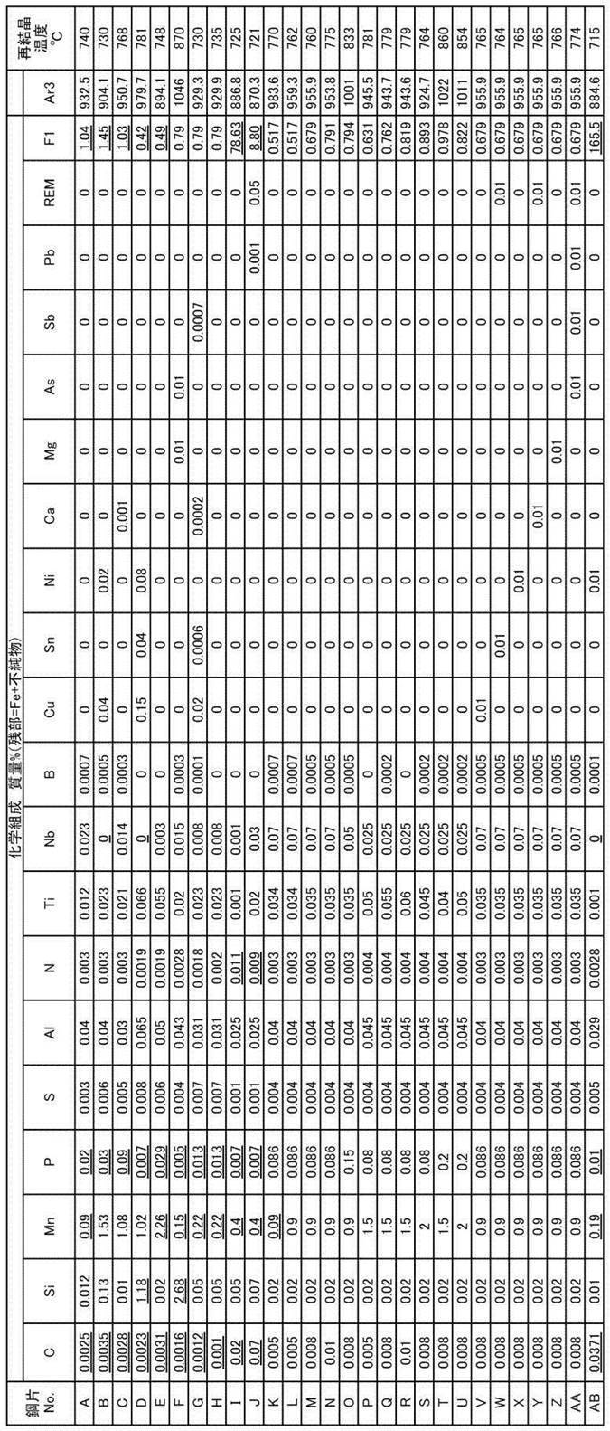
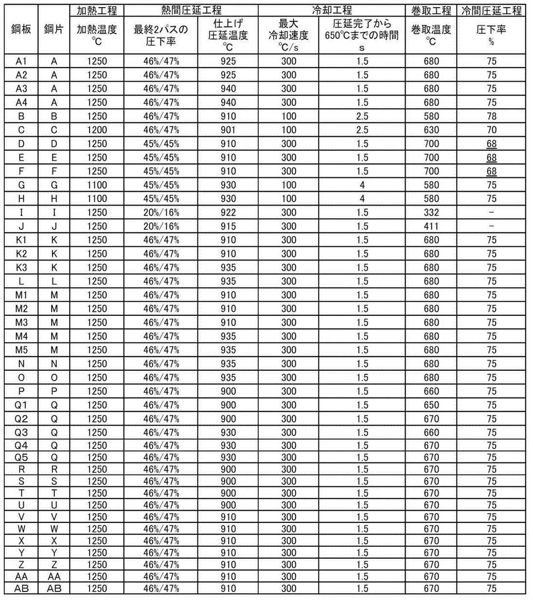

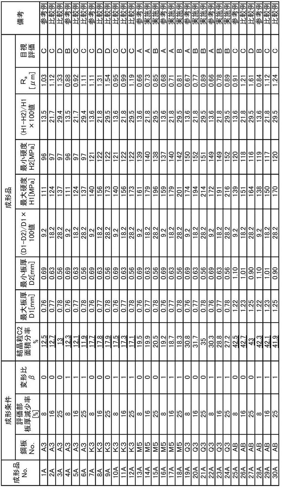
[成形品の成形シミュレーション]
参考例Aにおいて使用したbcc構造を有する金属板の断面を用いて、fcc構造を有する金属板の断面の結晶粒をモデリングした。そして、fcc構造を有する金属板の断面の結晶粒の粒径を変化させると共に、結晶粒Aおよび結晶粒Bの平均面積分率を変化させて、表6に示す特性を持つ仮想材をモデリングした。
次に、モデリングした仮想材に対して、絞り張り出し加工による図7に示す成形品の成形(実施例Aと同様の成形品の成形)に相当する成形シミュレーションを実施した。つまり、モデリングした仮想材に対して、成形品の評価部(稜線の延在方向に直交する断面における前記稜線の最小曲率半径の曲げ外部)となる仮想材の塑性ひずみ量に相当する「板厚減少率」を付与する成形シミュレーションを実施した。
具体的には、まず、仮想材に表6に示す「相当塑性ひずみ」となる変位を付与するため、モデル形状のプレス成形シミュレーション(以下、プレス成形シミュレーションという)を有限要素解析法で実施した。
それにより、プレス成形シミュレーション実施後の仮想材における、「最大板厚D1(成形品の最大板厚D1に相当)」、「最小板厚D2(成形品の最小板厚D2に相当)」、最大ビッカース硬さH1(成形品の最大ビッカース硬さH1に相当)、及び「最小ビッカース硬さH2(成形品の最小ビッカース硬さH2に相当)」を算出した。
そして、このプレス成形シミュレーションに相当する仮想材の成形シミュレーションとして、仮想材の断面の左右、手前、及び奥行き方向に、表6に示す「相当塑性ひずみ」となる変位を付与し、2軸引張変形させる成形シミュレーション(以下、成形シミュレーションという)を結晶塑性有限要素解析法で実施した。
最大板厚D1は、プレス成形品の板面内で板厚が最大となる場所での板厚である。
最小板厚D2は、プレス成形品の板面内で板厚が最小となる場所での板厚である。
最大ビッカース硬さH1は、成形前のビッカース硬さを仮想材の平均降伏強度YP1(MPa)から下記式により計算した。
・式:最大ビッカース硬さH1=YP1(MPa)/3
最小ビッカース硬さH2は、成形後(加工硬化後)のビッカース硬さを前記仮想材の平均降伏強度YP2(MPa)から下記式により計算した。
・式:最大ビッカース硬さH2=YP2(MPa)/3
また、成形後(加工硬化後)のビッカース硬さを仮想材の平均降伏強度YP2(MPa)は、6000系アルミ合金板の機械特性を入力した前記プレス成形シミュレーションにより前記プレス成形品の板面内で板厚が最小となる場所での相当応力値を用いて算出した。
なお、板厚減少率が10%未満である成形シミュレーション条件の例については、ひずみの量が少なく表面凹凸が起こらない例であるため、参考例と記載する。
前記成形シミュレーション実施後の仮想材について、次の方法により、表面の凹凸高さを算出した。前記成形シミュレーション実施後の仮想材の表面プロファイルを仮想材の断面曲線とし、前記断面曲線の最大値と最小値から算出した。
前記成形シミュレーション実施後の仮想材の表面性状について、仮想材の断面曲線を得た後、断面曲線の算術平均高さPaを算出した。そして、下記評価基準で評価した。
断面曲線の算術平均高さPaは、JIS B0601(2001)に規定された算術平均高さである。測定条件は、次の通りである。
・評価長さ:1mm
・基準長さ:1mm
A:Pa≦0.75μm(自動車外板部品としてより望ましく、高級車の外板部品としても利用できる。)
B:0.75μm<Pa≦0.95μm(自動車部品として利用できる。)
C:0.95μm<Pa≦1.30μm(自動車の外板部品として利用できない。)
D:1.30μm<Pa(自動車の部品として利用できない。)

上記のように、fcc構造を有する仮想材を、平面ひずみ引張変形および二軸変形が生じる成形シミュレーションを実施した結果、bcc構造を有する鋼板と同様に、成形品の表面荒れが抑制されていることがわかる。
10 金属板の成形品
11 金属板
12 金属板の成形品の稜線部
14 金属板の成形品の天板部
14A 稜線部の延在方向に沿った金属板の成形品の肩部
14B 稜線部の延在方向と交わる金属板の成形品の肩部
16 金属板の成形品の縦壁部
16A 稜線部の延在方向に沿った金属板の成形品の縦壁部
16B 稜線部の延在方向と交わる金属板の成形品の縦壁部
18 金属板の成形品のフランジ
18A 稜線部の直交方向上にある金属板の成形品のフランジ
18B 稜線部の延在方向上にある金属板の成形品のフランジ
本明細書に記載された全ての文献、特許出願、および技術規格は、個々の文献、特許出願、および技術規格が参照により取り込まれることが具体的かつ個々に記された場合と同程度に、本明細書中に参照により取り込まれる。
Claims (23)
- bcc構造を有し、表面において下記(a1)又は(b1)の条件を満たす金属板。
(a1) 前記金属板の表面に平行な{111}面から20°以上かつ{001}面から20°以上離れた結晶方位をもつ結晶粒の面積分率が0.25以上0.35以下であり、かつ平均結晶粒径が16μm未満である。
(b1) 前記金属板の表面に平行な{111}面から20°以上かつ{001}面から20°以上離れた結晶方位をもつ結晶粒の面積分率が0.15以上0.30以下であり、かつ平均結晶粒径が16μm以上である。 - bcc構造を有し、表面において下記(c1)の条件を満たす金属板。
(c1) 前記金属板の面内において、短手方向の平面ひずみ引張変形を仮定したときのTaylor Factorの値が3.0以上3.4以下を示す結晶粒の面積分率が0.18以上0.40以下である。 - 前記金属板が、鋼板である請求項1又は請求項2に記載の金属板。
- 前記鋼板が、表面の金属組織のフェライト分率50%以上のフェライト系鋼板である請求項3に記載の金属板。
- 前記鋼板が、質量%で、
C:0.0040%~0.0100%
Si:0%~1.0%、
Mn:0.90%~2.00%、
P:0.050%~0.200%
S:0%~0.010%、
Al:0.00050%~0.10%、
N:0%~0.0040%、
Ti:0.0010%~0.10%、
Nb:0.0010%~0.10%、
B:0%~0.003%、
CuおよびSnの1種以上の合計:0%~0.10%
Ni、Ca、Mg、Y、As、Sb、PbおよびREMの1種以上の合計:0%~0.10%、並びに、
残部:Fe及び不純物からなり、
下記式(1)で定義されるF1の値が0.5以上1.0以下である化学組成を有するフェライト系鋼板である請求項3又は請求項4に記載の金属板。
式(1):F1=(C/12+N/14+S/32)/(Ti/48+Nb/93) - 前記鋼板の化学組成が、質量%で、
CuおよびSnの1種以上の合計:0.002%~0.10%、及び
Ni、Ca、Mg、Y、As、Sb、PbおよびREMの1種以上の合計:0.005%~0.10%
の1種又は2種以上を含有する請求項5に記載の金属板。 - 熱間圧延板に対して、圧下率70%以上の冷間圧延を施し、冷間圧延板を得ることと、
焼鈍温度を再結晶温度+25℃以下、板面内の温度ムラを±10℃以内、焼鈍時間を100秒以内とする条件で、前記冷間圧延板を焼鈍することと、
を有する請求項5又は請求項6に記載の金属板の製造方法。 - 請求項1~請求項6のいずれか1項に記載の金属板に対して、平面ひずみ引張変形および二軸引張変形が生じ、かつ前記金属板の少なくとも一部が板厚減少率10%以上30%以下となる成形加工を施し、成形品を製造する金属板の成形品の製造方法。
- bcc構造を有し、稜線部を備えた金属板の成形品であって、
下記(BD)及び(BH)を満たし、かつ最大板厚部の表面において下記(a2)又は(b2)の条件を満たす金属板の成形品。
(BD) 前記成形品の最大板厚をD1とし、前記成形品の最小板厚をD2としたとき、式:10≦(D1-D2)/D1×100≦30の条件。
(BH) 前記成形品の最大ビッカース硬さをH1とし、前記成形品の最小ビッカース硬さをH2としたとき、式:15≦(H1-H2)/H1×100≦40の条件。
(a2) 前記成形品の表面に平行な{111}面から20°以上かつ{001}面から20°以上離れた結晶方位をもつ結晶粒の面積分率が0.25以上0.35以下であり、かつ平均結晶粒径が16μm未満である。
(b2) 前記成形品の表面に平行な{111}面から20°以上かつ{001}面から20°以上離れた結晶方位をもつ結晶粒の面積分率が0.15以上0.30以下であり、かつ平均結晶粒径が16μm以上である。 - bcc構造を有し、稜線部を備えた金属板の成形品であって、
下記(BD)及び(BH)を満たし、かつ最大板厚部の表面において下記(c2)の条件を満たす金属板の成形品。
(BD) 前記成形品の最大板厚をD1とし、前記成形品の最小板厚をD2としたとき、式:10≦(D1-D2)/D1×100≦30の条件。
(BH) 前記成形品の最大ビッカース硬さをH1とし、前記成形品の最小ビッカース硬さをH2としたとき、式:15≦(H1-H2)/H1×100≦40の条件。
(c2) 前記稜線部の延在方向に対する直交方向断面の前記稜線部の凹側表面の曲率半径最小部における、前記稜線部の延在方向に対する直交方向の平面ひずみ引張変形を仮定したときのTaylor Factorの値が3.0以上3.4以下を示す結晶粒の面積分率が0.18以上0.35以下である。 - 前記金属板が、鋼板である請求項9又は請求項10に記載の金属板の成形品。
- 前記鋼板が、表面の金属組織のフェライト分率50%以上のフェライト系鋼板である請求項11に記載の金属板の成形品。
- 前記鋼板が、質量%で、
C:0.0040%~0.0100%
Si:0%~1.0%、
Mn:0.90%~2.00%、
P:0.050%~0.200%
S:0%~0.010%、
Al:0.00050%~0.10%、
N:0%~0.0040%、
Ti:0.0010%~0.10%、
Nb:0.0010%~0.10%、
B:0%~0.003%、
CuおよびSnの1種以上の合計:0%~0.10%
Ni、Ca、Mg、As、Sb、PbおよびREMの1種以上の合計:0%~0.10%、並びに、
残部:Fe及び不純物からなり、
下記式(1)で定義されるF1の値が0.5以上1.0以下である化学組成を有するフェライト系鋼板である請求項11又は請求項12に記載の金属板の成形品。
式(1):F1=(C/12+N/14+S/32)/(Ti/48+Nb/93) - 前記鋼板の化学組成が、質量%で、
CuおよびSnの1種以上の合計:0.002%~0.10%、及び
Ni、Ca、Mg、As、Sb、PbおよびREMの1種以上の合計:0.005%~0.10%
の1種又は2種以上を含有する請求項13に記載の金属板の成形品。 - fcc構造を有し、表面において下記(a1)又は(b1)の条件を満たす金属板。
(a1) 前記金属板の表面に平行な{111}面から20°以上かつ{001}面から20°以上離れた結晶方位をもつ結晶粒の面積分率が0.25以上0.35以下であり、かつ平均結晶粒径が16μm未満である。
(b1) 前記金属板の表面に平行な{111}面から20°以上かつ{001}面から20°以上離れた結晶方位をもつ結晶粒の面積分率が0.15以上0.30以下であり、かつ平均結晶粒径が16μm以上である。 - fcc構造を有し、表面において下記(c1)の条件を満たす金属板。
(c1)金属板の面内において、短手方向の平面ひずみ引張変形を仮定したときのTaylor Factorの値が3.0以上3.4以下を示す結晶粒の面積分率が0.18以上0.40以下である。 - 前記金属板が、オーステナイト系ステンレス鋼板である請求項15又は請求項16に記載の金属板。
- 前記金属板が、アルミニウム合金板である請求項15又は請求項16に記載の金属板。
- 請求項15~請求項18のいずれか1項に記載の金属板に対して、平面ひずみ引張変形および二軸引張変形が生じ、かつ前記金属板の少なくとも一部が板厚減少率5%以上30%以下となる成形加工を施し、成形品を製造する金属板の成形品の製造方法。
- fcc構造を有し、稜線部を備えた金属板の成形品であって、
下記(FD)及び(FH)を満たし、かつ最大板厚部の表面において下記(a2)又は(b2)の条件を満たす金属板の成形品。
(FD) 前記成形品の最大板厚をD1とし、前記成形品の最小板厚をD2としたとき、式:5≦(D1-D2)/D1×100≦30の条件。
(FH) 前記成形品の最大ビッカース硬さをH1とし、前記成形品の最小ビッカース硬さをH2としたとき、式:7≦(H1-H2)/H1×100≦40の条件。
(a2) 前記成形品の表面に平行な{111}面から20°以上かつ{001}面から20°以上離れた結晶方位をもつ結晶粒の面積分率が0.25以上0.35以下、かつ平均結晶粒径が16μm未満である。
(b2) 前記成形品の表面に平行な{111}面から20°以上かつ{001}面から20°以上離れた結晶方位をもつ結晶粒の面積分率が0.15以上0.30以下、かつ平均結晶粒径が16μm以上である。 - fcc構造を有し、稜線部を備えた金属板の成形品であって、
下記(FD)及び(FH)を満たし、かつ最大板厚部の表面において下記(c2)の条件を満たす金属板の成形品。
(FD) 前記成形品の最大板厚をD1とし、前記成形品の最小板厚をD2としたとき、式:5≦(D1-D2)/D1×100≦30の条件。
(FH) 前記成形品の最大ビッカース硬さをH1とし、前記成形品の最小ビッカース硬さをH2としたとき、式:7≦(H1-H2)/H1×100≦40の条件。
(c2) 前記稜線部の延在方向に対する直交方向断面の前記稜線部の凹側表面の曲率半径最小部における、前記稜線部の延在方向に対する直交方向の平面ひずみ引張変形を仮定したときのTaylor Factorの値が3.0以上3.4以下を示す結晶粒の面積分率が0.18以上0.35以下である。 - 前記金属板が、オーステナイト系ステンレス鋼板である請求項20又は請求項21に記載の金属板の成形品。
- 前記金属板が、アルミニウム合金板である請求項20又は請求項21に記載の金属板の成形品。
Priority Applications (6)
| Application Number | Priority Date | Filing Date | Title |
|---|---|---|---|
| EP19781740.6A EP3778968B1 (en) | 2018-04-02 | 2019-04-02 | Metal sheet, method for manufacturing metal sheet, method of producing molded product of metal sheet, and molded product of metal sheet |
| JP2019566374A JP6753542B2 (ja) | 2018-04-02 | 2019-04-02 | 金属板、金属板の製造方法、金属板の成形品の製造方法および金属板の成形品 |
| KR1020207029766A KR102276818B1 (ko) | 2018-04-02 | 2019-04-02 | 금속판, 금속판의 제조 방법, 금속판의 성형품의 제조 방법, 및 금속판의 성형품 |
| MX2020010273A MX388648B (es) | 2018-04-02 | 2019-04-02 | Lamina de metal, metodo de produccion de lamina de metal, metodo de produccion de producto moldeado de lamina de metal y producto moldeado de lamina de metal |
| US17/044,106 US11035022B2 (en) | 2018-04-02 | 2019-04-02 | Metal sheet, method of producing metal sheet, method of producing molded product of metal sheet, and molded product of metal sheet |
| CN201980023914.0A CN111936652B (zh) | 2018-04-02 | 2019-04-02 | 金属板、金属板的制造方法、金属板的成型品的制造方法及金属板的成型品 |
Applications Claiming Priority (2)
| Application Number | Priority Date | Filing Date | Title |
|---|---|---|---|
| JP2018071080 | 2018-04-02 | ||
| JP2018-071080 | 2018-04-02 |
Publications (1)
| Publication Number | Publication Date |
|---|---|
| WO2019194201A1 true WO2019194201A1 (ja) | 2019-10-10 |
Family
ID=68100223
Family Applications (1)
| Application Number | Title | Priority Date | Filing Date |
|---|---|---|---|
| PCT/JP2019/014693 Ceased WO2019194201A1 (ja) | 2018-04-02 | 2019-04-02 | 金属板、金属板の製造方法、金属板の成形品の製造方法および金属板の成形品 |
Country Status (7)
| Country | Link |
|---|---|
| US (1) | US11035022B2 (ja) |
| EP (1) | EP3778968B1 (ja) |
| JP (1) | JP6753542B2 (ja) |
| KR (1) | KR102276818B1 (ja) |
| CN (1) | CN111936652B (ja) |
| MX (1) | MX388648B (ja) |
| WO (1) | WO2019194201A1 (ja) |
Cited By (1)
| Publication number | Priority date | Publication date | Assignee | Title |
|---|---|---|---|---|
| US20240194899A1 (en) * | 2021-05-31 | 2024-06-13 | Posco Co., Ltd | Steel sheet having excellent hydrophilicity and conductivity |
Families Citing this family (3)
| Publication number | Priority date | Publication date | Assignee | Title |
|---|---|---|---|---|
| KR102326257B1 (ko) * | 2021-05-31 | 2021-11-16 | 주식회사 포스코 | 친수성 및 도전성이 우수한 강판 |
| KR20240146658A (ko) * | 2022-02-03 | 2024-10-08 | 타타 스틸 이즈무이덴 베.뷔. | 성형성이 향상된 저탄소 강대의 제조 방법 |
| CN114659872B (zh) * | 2022-03-11 | 2024-06-18 | 中国航发北京航空材料研究院 | 一种评价单晶高温合金空心叶片型芯退让性的方法 |
Citations (6)
| Publication number | Priority date | Publication date | Assignee | Title |
|---|---|---|---|---|
| JPS6156613B2 (ja) | 1977-04-08 | 1986-12-03 | Nippon Electric Co | |
| JPH11117038A (ja) * | 1997-10-09 | 1999-04-27 | Kawasaki Steel Corp | 加工性と耐肌荒れ性および耐リジング性に優れた冷延鋼板 |
| JP5683193B2 (ja) | 2010-09-30 | 2015-03-11 | 株式会社Uacj | 耐リジング性に優れた成形加工用アルミニウム合金圧延板およびその製造方法 |
| WO2017098983A1 (ja) * | 2015-12-11 | 2017-06-15 | 新日鐵住金株式会社 | 成形品の製造方法、及び成形品 |
| JP2018071080A (ja) | 2016-10-25 | 2018-05-10 | 株式会社東京架設 | 仮設足場用跳ね出し架台 |
| JP2018080386A (ja) * | 2016-11-09 | 2018-05-24 | 日新製鋼株式会社 | フェライト系ステンレス鋼板 |
Family Cites Families (13)
| Publication number | Priority date | Publication date | Assignee | Title |
|---|---|---|---|---|
| JP3451830B2 (ja) * | 1996-03-29 | 2003-09-29 | Jfeスチール株式会社 | 耐リジング性および加工性に優れたフェライト系ステンレス鋼板およびその製造方法 |
| JPH117038A (ja) | 1997-06-17 | 1999-01-12 | Alps Electric Co Ltd | 液晶表示装置、並びにこの液晶表示装置の製造方法 |
| WO2004003247A1 (en) * | 2002-06-28 | 2004-01-08 | Posco | Super formable high strength steel sheet and method of manufacturing thereof |
| JP5337473B2 (ja) * | 2008-02-05 | 2013-11-06 | 新日鐵住金ステンレス株式会社 | 耐リジング性と加工性に優れたフェライト・オーステナイト系ステンレス鋼板およびその製造方法 |
| KR101193756B1 (ko) * | 2009-10-29 | 2012-10-23 | 현대제철 주식회사 | 표면특성이 우수한 고강도 고성형 강판 및 그 제조방법 |
| CN102839328A (zh) * | 2011-06-24 | 2012-12-26 | 宝山钢铁股份有限公司 | 高深冲性低各向异性的铁素体不锈钢板及其制造方法 |
| KR20140108214A (ko) * | 2012-04-19 | 2014-09-05 | 신닛테츠스미킨 카부시키카이샤 | 강박 및 그 제조 방법 |
| WO2014021382A1 (ja) * | 2012-07-31 | 2014-02-06 | 新日鐵住金株式会社 | 冷延鋼鈑、電気亜鉛系めっき冷延鋼板、溶融亜鉛めっき冷延鋼板、合金化溶融亜鉛めっき冷延鋼板、及び、それらの製造方法 |
| JP6416776B2 (ja) * | 2013-11-15 | 2018-10-31 | 住友電工ハードメタル株式会社 | ダイヤモンド接合体、それを備える工具、およびダイヤモンド接合体の製造方法 |
| JP6179674B2 (ja) * | 2014-10-30 | 2017-08-16 | Jfeスチール株式会社 | 高強度鋼板、高強度溶融亜鉛めっき鋼板、高強度溶融アルミニウムめっき鋼板および高強度電気亜鉛めっき鋼板、ならびに、それらの製造方法 |
| JP6443126B2 (ja) * | 2015-02-26 | 2018-12-26 | 新日鐵住金株式会社 | フェライト系薄鋼板 |
| KR101819358B1 (ko) * | 2016-08-12 | 2018-01-17 | 주식회사 포스코 | 성형성이 우수한 고강도 박강판 및 그 제조방법 |
| CN109136735A (zh) * | 2017-06-27 | 2019-01-04 | 宝钢不锈钢有限公司 | 具有良好成形性能的铁素体不锈钢及其制造方法 |
-
2019
- 2019-04-02 KR KR1020207029766A patent/KR102276818B1/ko active Active
- 2019-04-02 US US17/044,106 patent/US11035022B2/en active Active
- 2019-04-02 MX MX2020010273A patent/MX388648B/es unknown
- 2019-04-02 CN CN201980023914.0A patent/CN111936652B/zh active Active
- 2019-04-02 JP JP2019566374A patent/JP6753542B2/ja active Active
- 2019-04-02 WO PCT/JP2019/014693 patent/WO2019194201A1/ja not_active Ceased
- 2019-04-02 EP EP19781740.6A patent/EP3778968B1/en active Active
Patent Citations (6)
| Publication number | Priority date | Publication date | Assignee | Title |
|---|---|---|---|---|
| JPS6156613B2 (ja) | 1977-04-08 | 1986-12-03 | Nippon Electric Co | |
| JPH11117038A (ja) * | 1997-10-09 | 1999-04-27 | Kawasaki Steel Corp | 加工性と耐肌荒れ性および耐リジング性に優れた冷延鋼板 |
| JP5683193B2 (ja) | 2010-09-30 | 2015-03-11 | 株式会社Uacj | 耐リジング性に優れた成形加工用アルミニウム合金圧延板およびその製造方法 |
| WO2017098983A1 (ja) * | 2015-12-11 | 2017-06-15 | 新日鐵住金株式会社 | 成形品の製造方法、及び成形品 |
| JP2018071080A (ja) | 2016-10-25 | 2018-05-10 | 株式会社東京架設 | 仮設足場用跳ね出し架台 |
| JP2018080386A (ja) * | 2016-11-09 | 2018-05-24 | 日新製鋼株式会社 | フェライト系ステンレス鋼板 |
Non-Patent Citations (3)
| Title |
|---|
| R. BECKER: "Effects of strain localization on surface roughening during sheet forming", ACTA MATER, vol. 46, no. 4, 1998, pages 1385 - 1401, XP026116780, DOI: 10.1016/S1359-6454(97)00182-1 |
| See also references of EP3778968A4 |
| SUZUKI, SEIICHI: "Example of rolling texture analysis by EBSD", JOURNAL OF JAPAN INSTITUTE OF LIGHT METALS, vol. 66, no. 11, November 2016 (2016-11-01), pages 566 - 573, XP055644943 * |
Cited By (1)
| Publication number | Priority date | Publication date | Assignee | Title |
|---|---|---|---|---|
| US20240194899A1 (en) * | 2021-05-31 | 2024-06-13 | Posco Co., Ltd | Steel sheet having excellent hydrophilicity and conductivity |
Also Published As
| Publication number | Publication date |
|---|---|
| MX388648B (es) | 2025-03-20 |
| EP3778968A4 (en) | 2021-12-15 |
| US11035022B2 (en) | 2021-06-15 |
| CN111936652A (zh) | 2020-11-13 |
| EP3778968B1 (en) | 2023-05-24 |
| JPWO2019194201A1 (ja) | 2020-04-30 |
| KR20200124309A (ko) | 2020-11-02 |
| US20210017623A1 (en) | 2021-01-21 |
| JP6753542B2 (ja) | 2020-09-09 |
| MX2020010273A (es) | 2021-12-10 |
| EP3778968A1 (en) | 2021-02-17 |
| CN111936652B (zh) | 2021-06-29 |
| KR102276818B1 (ko) | 2021-07-15 |
Similar Documents
| Publication | Publication Date | Title |
|---|---|---|
| JP6156613B1 (ja) | 成形品の製造方法、及び成形品 | |
| CN103562428B (zh) | 冷轧钢板及其制造方法 | |
| JP6753542B2 (ja) | 金属板、金属板の製造方法、金属板の成形品の製造方法および金属板の成形品 | |
| CN109844158B (zh) | 用于涂漆零件的钢基底 | |
| JP6809652B2 (ja) | 鋼板及びその製造方法 | |
| KR102562003B1 (ko) | 강판 및 그 제조 방법 | |
| CN109844159B (zh) | 用于涂漆零件的钢 | |
| JP2007291514A (ja) | 冷延−再結晶焼鈍後の面内異方性が小さい熱延鋼板、面内異方性が小さい冷延鋼板およびそれらの製造方法 | |
| JP5937865B2 (ja) | プレス成形性と強度のバランス、及び耐食性に優れた純チタン板の製造方法 | |
| WO2023026469A1 (ja) | 自動車用外板部品、ブランクシート、ブランクシートの製造方法、及びブランクシートの製造設備 | |
| WO2022004795A1 (ja) | 外装パネルおよびそれを備える自動車 | |
| JP6809651B2 (ja) | 鋼板及びその製造方法 | |
| JP6954211B2 (ja) | 金属成形板、塗装金属成形板および成形方法 | |
| JP6776908B2 (ja) | 成形品の製造方法、及び成形品 | |
| JP2019131875A (ja) | 金属成形板、絞り成形方法、および絞り成形金型 | |
| TWI554618B (zh) | 高強度熱軋鋼板 | |
| JP2019072861A (ja) | 金属板、管状成形品、およびプレス成形品 | |
| WO2025234230A1 (ja) | 鋼板、それを含む部品及び鋼板の製造方法 |
Legal Events
| Date | Code | Title | Description |
|---|---|---|---|
| 121 | Ep: the epo has been informed by wipo that ep was designated in this application |
Ref document number: 19781740 Country of ref document: EP Kind code of ref document: A1 |
|
| ENP | Entry into the national phase |
Ref document number: 2019566374 Country of ref document: JP Kind code of ref document: A |
|
| NENP | Non-entry into the national phase |
Ref country code: DE |
|
| ENP | Entry into the national phase |
Ref document number: 20207029766 Country of ref document: KR Kind code of ref document: A |
|
| ENP | Entry into the national phase |
Ref document number: 2019781740 Country of ref document: EP Effective date: 20201102 |