WO2019196135A1 - 一种激光雷达系统和激光测距方法 - Google Patents
一种激光雷达系统和激光测距方法 Download PDFInfo
- Publication number
- WO2019196135A1 WO2019196135A1 PCT/CN2018/084241 CN2018084241W WO2019196135A1 WO 2019196135 A1 WO2019196135 A1 WO 2019196135A1 CN 2018084241 W CN2018084241 W CN 2018084241W WO 2019196135 A1 WO2019196135 A1 WO 2019196135A1
- Authority
- WO
- WIPO (PCT)
- Prior art keywords
- laser
- optical fiber
- fiber array
- lens
- receivers
- Prior art date
- Legal status (The legal status is an assumption and is not a legal conclusion. Google has not performed a legal analysis and makes no representation as to the accuracy of the status listed.)
- Ceased
Links
Images




Classifications
-
- G—PHYSICS
- G01—MEASURING; TESTING
- G01S—RADIO DIRECTION-FINDING; RADIO NAVIGATION; DETERMINING DISTANCE OR VELOCITY BY USE OF RADIO WAVES; LOCATING OR PRESENCE-DETECTING BY USE OF THE REFLECTION OR RERADIATION OF RADIO WAVES; ANALOGOUS ARRANGEMENTS USING OTHER WAVES
- G01S7/00—Details of systems according to groups G01S13/00, G01S15/00, G01S17/00
- G01S7/48—Details of systems according to groups G01S13/00, G01S15/00, G01S17/00 of systems according to group G01S17/00
- G01S7/481—Constructional features, e.g. arrangements of optical elements
- G01S7/4817—Constructional features, e.g. arrangements of optical elements relating to scanning
-
- G—PHYSICS
- G01—MEASURING; TESTING
- G01S—RADIO DIRECTION-FINDING; RADIO NAVIGATION; DETERMINING DISTANCE OR VELOCITY BY USE OF RADIO WAVES; LOCATING OR PRESENCE-DETECTING BY USE OF THE REFLECTION OR RERADIATION OF RADIO WAVES; ANALOGOUS ARRANGEMENTS USING OTHER WAVES
- G01S17/00—Systems using the reflection or reradiation of electromagnetic waves other than radio waves, e.g. lidar systems
- G01S17/02—Systems using the reflection of electromagnetic waves other than radio waves
- G01S17/06—Systems determining position data of a target
- G01S17/08—Systems determining position data of a target for measuring distance only
-
- G—PHYSICS
- G01—MEASURING; TESTING
- G01S—RADIO DIRECTION-FINDING; RADIO NAVIGATION; DETERMINING DISTANCE OR VELOCITY BY USE OF RADIO WAVES; LOCATING OR PRESENCE-DETECTING BY USE OF THE REFLECTION OR RERADIATION OF RADIO WAVES; ANALOGOUS ARRANGEMENTS USING OTHER WAVES
- G01S17/00—Systems using the reflection or reradiation of electromagnetic waves other than radio waves, e.g. lidar systems
- G01S17/02—Systems using the reflection of electromagnetic waves other than radio waves
- G01S17/06—Systems determining position data of a target
- G01S17/08—Systems determining position data of a target for measuring distance only
- G01S17/10—Systems determining position data of a target for measuring distance only using transmission of interrupted, pulse-modulated waves
-
- G—PHYSICS
- G01—MEASURING; TESTING
- G01S—RADIO DIRECTION-FINDING; RADIO NAVIGATION; DETERMINING DISTANCE OR VELOCITY BY USE OF RADIO WAVES; LOCATING OR PRESENCE-DETECTING BY USE OF THE REFLECTION OR RERADIATION OF RADIO WAVES; ANALOGOUS ARRANGEMENTS USING OTHER WAVES
- G01S17/00—Systems using the reflection or reradiation of electromagnetic waves other than radio waves, e.g. lidar systems
- G01S17/02—Systems using the reflection of electromagnetic waves other than radio waves
- G01S17/06—Systems determining position data of a target
- G01S17/42—Simultaneous measurement of distance and other co-ordinates
-
- G—PHYSICS
- G01—MEASURING; TESTING
- G01S—RADIO DIRECTION-FINDING; RADIO NAVIGATION; DETERMINING DISTANCE OR VELOCITY BY USE OF RADIO WAVES; LOCATING OR PRESENCE-DETECTING BY USE OF THE REFLECTION OR RERADIATION OF RADIO WAVES; ANALOGOUS ARRANGEMENTS USING OTHER WAVES
- G01S7/00—Details of systems according to groups G01S13/00, G01S15/00, G01S17/00
- G01S7/48—Details of systems according to groups G01S13/00, G01S15/00, G01S17/00 of systems according to group G01S17/00
- G01S7/481—Constructional features, e.g. arrangements of optical elements
- G01S7/4811—Constructional features, e.g. arrangements of optical elements common to transmitter and receiver
-
- G—PHYSICS
- G01—MEASURING; TESTING
- G01S—RADIO DIRECTION-FINDING; RADIO NAVIGATION; DETERMINING DISTANCE OR VELOCITY BY USE OF RADIO WAVES; LOCATING OR PRESENCE-DETECTING BY USE OF THE REFLECTION OR RERADIATION OF RADIO WAVES; ANALOGOUS ARRANGEMENTS USING OTHER WAVES
- G01S7/00—Details of systems according to groups G01S13/00, G01S15/00, G01S17/00
- G01S7/48—Details of systems according to groups G01S13/00, G01S15/00, G01S17/00 of systems according to group G01S17/00
- G01S7/481—Constructional features, e.g. arrangements of optical elements
- G01S7/4814—Constructional features, e.g. arrangements of optical elements of transmitters alone
- G01S7/4815—Constructional features, e.g. arrangements of optical elements of transmitters alone using multiple transmitters
-
- G—PHYSICS
- G01—MEASURING; TESTING
- G01S—RADIO DIRECTION-FINDING; RADIO NAVIGATION; DETERMINING DISTANCE OR VELOCITY BY USE OF RADIO WAVES; LOCATING OR PRESENCE-DETECTING BY USE OF THE REFLECTION OR RERADIATION OF RADIO WAVES; ANALOGOUS ARRANGEMENTS USING OTHER WAVES
- G01S7/00—Details of systems according to groups G01S13/00, G01S15/00, G01S17/00
- G01S7/48—Details of systems according to groups G01S13/00, G01S15/00, G01S17/00 of systems according to group G01S17/00
- G01S7/481—Constructional features, e.g. arrangements of optical elements
- G01S7/4816—Constructional features, e.g. arrangements of optical elements of receivers alone
-
- G—PHYSICS
- G01—MEASURING; TESTING
- G01S—RADIO DIRECTION-FINDING; RADIO NAVIGATION; DETERMINING DISTANCE OR VELOCITY BY USE OF RADIO WAVES; LOCATING OR PRESENCE-DETECTING BY USE OF THE REFLECTION OR RERADIATION OF RADIO WAVES; ANALOGOUS ARRANGEMENTS USING OTHER WAVES
- G01S7/00—Details of systems according to groups G01S13/00, G01S15/00, G01S17/00
- G01S7/48—Details of systems according to groups G01S13/00, G01S15/00, G01S17/00 of systems according to group G01S17/00
- G01S7/481—Constructional features, e.g. arrangements of optical elements
- G01S7/4818—Constructional features, e.g. arrangements of optical elements using optical fibres
-
- G—PHYSICS
- G02—OPTICS
- G02B—OPTICAL ELEMENTS, SYSTEMS OR APPARATUS
- G02B27/00—Optical systems or apparatus not provided for by any of the groups G02B1/00 - G02B26/00, G02B30/00
- G02B27/09—Beam shaping, e.g. changing the cross-sectional area, not otherwise provided for
- G02B27/0916—Adapting the beam shape of a semiconductor light source such as a laser diode or an LED, e.g. for efficiently coupling into optical fibers
-
- G—PHYSICS
- G02—OPTICS
- G02B—OPTICAL ELEMENTS, SYSTEMS OR APPARATUS
- G02B27/00—Optical systems or apparatus not provided for by any of the groups G02B1/00 - G02B26/00, G02B30/00
- G02B27/09—Beam shaping, e.g. changing the cross-sectional area, not otherwise provided for
- G02B27/0938—Using specific optical elements
- G02B27/0944—Diffractive optical elements, e.g. gratings, holograms
-
- G—PHYSICS
- G02—OPTICS
- G02B—OPTICAL ELEMENTS, SYSTEMS OR APPARATUS
- G02B6/00—Light guides; Structural details of arrangements comprising light guides and other optical elements, e.g. couplings
- G02B2006/0098—Light guides; Structural details of arrangements comprising light guides and other optical elements, e.g. couplings for scanning
-
- G—PHYSICS
- G02—OPTICS
- G02B—OPTICAL ELEMENTS, SYSTEMS OR APPARATUS
- G02B27/00—Optical systems or apparatus not provided for by any of the groups G02B1/00 - G02B26/00, G02B30/00
- G02B27/09—Beam shaping, e.g. changing the cross-sectional area, not otherwise provided for
- G02B27/0938—Using specific optical elements
- G02B27/095—Refractive optical elements
- G02B27/0955—Lenses
- G02B27/0966—Cylindrical lenses
-
- G—PHYSICS
- G02—OPTICS
- G02B—OPTICAL ELEMENTS, SYSTEMS OR APPARATUS
- G02B6/00—Light guides; Structural details of arrangements comprising light guides and other optical elements, e.g. couplings
- G02B6/24—Coupling light guides
- G02B6/42—Coupling light guides with opto-electronic elements
- G02B6/4201—Packages, e.g. shape, construction, internal or external details
- G02B6/4249—Packages, e.g. shape, construction, internal or external details comprising arrays of active devices and fibres
Definitions
- the present application relates to the field of laser detection and ranging technology, and in particular, to a laser radar system and a laser ranging method.
- the Light Detection And Ranging (LiDAR) system is often referred to as a laser radar system.
- the basic working principle of Lidar is that the laser emitter emits laser light to the target object, and the receiver receives the emitted light of the target object.
- the laser radar calculates the distance from the laser radar to the target object according to the laser ranging principle.
- a laser transmitter and a receiver form a laser ranging channel.
- a common 3D laser radar is a mechanical rotary laser radar, which comprises a plurality of pairs of laser emitters and receivers, each pair of laser emitters and receivers facing different spatial angular positions, forming a fan cover, and then driving with a single axis rotation mechanism The plurality of pairs of laser emitters and receivers are rotated as a whole to realize three-dimensional laser scanning.
- the embodiment of the present application provides a laser radar system, comprising: a laser scanning component and a rotating component, wherein the rotating component is configured to rotate the laser scanning component; the laser scanning component comprises: a transmitting component, an emitting lens, a receiving component, and Receive lens.
- the above-mentioned transmitting component comprises a plurality of laser emitters and a first optical fiber array, wherein the plurality of laser emitters are in one-to-one correspondence with the plurality of optical fibers, wherein the laser light emitted by each of the laser emitters enters a corresponding optical fiber, and the plurality of lasers a plurality of optical fibers corresponding to the transmitter are connected to the first optical fiber array;
- the transmitting lens is configured to collimate and emit laser light from the first optical fiber array;
- the receiving component comprises a plurality of receivers and a second optical fiber array, The receivers are in one-to-one correspondence with the plurality of optical fibers, wherein each of the receivers receives the reflected light transmitted by the corresponding optical fiber, and the plurality of optical fibers corresponding to the plurality of receivers are connected to the second optical fiber array;
- the receiving lens is configured to receive the laser Reflecting light and concentrating the reflected light onto the second fiber array described above.
- the transmitting component further includes a first multi-core optical fiber connector, configured to connect the plurality of optical fibers corresponding to the plurality of laser emitters to the first optical fiber array; and the receiving component further comprises a second multi-core optical fiber connection And a plurality of optical fibers corresponding to the plurality of receivers connected to the second optical fiber array.
- the above-mentioned transmitting component further comprises a plurality of beam shapers, wherein the plurality of beam shapers are in one-to-one correspondence with the plurality of laser emitters, and the beam shaper is configured to couple the laser light emitted by the laser emitter into the corresponding optical fiber.
- the beam shaper may be a double cylindrical lens, and the bus bars of the two cylinders of the double cylindrical lens are orthogonal to each other.
- the beam shaper may be an optical diffraction based beam shaper comprising: a collimating lens, a first diffractive element and a second diffractive element.
- the collimating lens is used for collimating the light beam emitted by the laser emitter in the fast axis direction to become an elongated strip beam
- the first diffractive element is configured to divide the elongated strip beam into a plurality of beams, In addition to the central beam, the remaining beams are respectively deflected to different spatial orientations
- the second diffractive element is used to correct the remaining beams such that the remaining beams overlap with the central beam and are focused to the end faces of the corresponding fibers.
- the beam shaper may be another optical diffraction-based beam shaper comprising: a first lens, a first diffraction element, a second diffraction element, and a second lens.
- the first lens is configured to collimate the light beam emitted by the laser emitter in a fast axis direction to become an elongated strip beam
- the first diffractive element is configured to divide the elongated strip beam into a plurality of beams, In addition to the central beam, the remaining beams are respectively deflected to different spatial orientations
- the second diffractive element is used to correct the remaining beams such that the remaining beams are parallel to the central beam
- the second lens is used to The remaining light beams of the second diffraction element overlap with the center beam and are focused to the end faces of the corresponding fibers.
- the receiving component may further include a plurality of microlenses, and the plurality of microlenses are in one-to-one correspondence with the plurality of receivers for concentrating the reflected light conducted by the optical fibers to the corresponding receiver.
- first optical fiber array is on a focal plane of the transmitting lens
- second optical fiber array is on a focal plane of the receiving lens.
- first optical fiber array may be a one-dimensional optical fiber array or a two-dimensional optical fiber array
- second optical fiber array may be a one-dimensional optical fiber array or a two-dimensional optical fiber array.
- the embodiment of the present application further provides a laser ranging method, which uses a laser radar system to perform laser ranging
- the laser radar system includes a laser scanning component and a rotating component
- the laser scanning component includes a transmitting component, an emitting lens, a receiving component, and a receiving lens
- the transmitting component includes a plurality of laser emitters and a first fiber array, wherein the plurality of laser emitters are in one-to-one correspondence with the plurality of optical fibers, and the plurality of optical fibers corresponding to the plurality of laser emitters are connected to the first optical fiber array
- the receiving component includes a plurality of receivers and a second fiber array, wherein the plurality of receivers are in one-to-one correspondence with the plurality of fibers, and the plurality of fibers corresponding to the plurality of receivers are connected to the second fiber array.
- the rotating member rotates the laser scanning component; the plurality of laser emitters emit laser light, the laser light is transmitted through a corresponding optical fiber, and is emitted from the first optical fiber array; and the transmitting lens passes a laser from the first optical fiber array Directly transmitting; the receiving lens receives the reflected light of the laser light, and condenses the reflected light to the second optical fiber array; and the plurality of receivers receive the reflected light transmitted by the corresponding optical fiber.
- the foregoing transmitting component may further include a first multi-core optical fiber connector, wherein the plurality of optical fibers corresponding to the plurality of laser emitters are connected to the first optical fiber array, including: using the first multi-core optical fiber connector a plurality of optical fibers corresponding to the plurality of laser emitters are connected to the first optical fiber array; the receiving component further includes a second multi-core optical fiber connector, wherein the plurality of optical fibers corresponding to the plurality of receivers are connected to the second optical fiber array
- the method includes: connecting, by the second multi-core fiber connector, the plurality of fibers corresponding to the plurality of receivers to the second fiber array.
- the above-mentioned transmitting component further comprises a plurality of beam shapers, wherein the plurality of beam shapers are in one-to-one correspondence with the plurality of laser emitters, and the beam shaper couples the laser light emitted by the laser emitter into the corresponding optical fiber.
- the beam shaper is a double cylindrical lens, and the bus bars of the two cylinders of the double cylindrical lens are orthogonal to each other.
- the beam shaper may be an optical diffraction based beam shaper comprising: a collimating lens, a first diffractive element and a second diffractive element.
- the beam shaper couples the laser light emitted by the laser emitter into the corresponding optical fiber, comprising: the collimating lens collimating the light beam emitted by the laser emitter in a fast axis direction to become an elongated strip beam; a diffractive element divides the elongated strip beam into a plurality of beams, and the other beams are respectively deflected to different spatial orientations except for the central beam; the second diffractive element corrects the remaining beams to make the remaining beams and the above The center beams overlap and are focused to the end faces of the corresponding fibers.
- the beam shaper may be another optical diffraction-based beam shaper comprising: a first lens, a first diffraction element, a second diffraction element, and a second lens.
- the beam shaper couples the laser light emitted by the laser emitter into the corresponding optical fiber, comprising: the first lens collimating the light beam emitted by the laser emitter in a fast axis direction to become an elongated strip beam; a diffractive element divides the elongated strip beam into a plurality of beams, and the other beams are respectively deflected to different spatial orientations except for the central beam; the second diffractive element corrects the remaining beams to make the remaining beams and the above The center beam is parallel; the second lens overlaps the remaining beams from the second diffractive element and the center beam and focuses on an end face of the corresponding fiber.
- the receiving component may further include a plurality of microlenses, wherein the plurality of microlenses are in one-to-one correspondence with the plurality of receivers, and the microlenses converge the reflected light conducted by the optical fibers to the corresponding receiver.
- an end surface of the first optical fiber array is on a focal plane of the transmitting lens, and an end surface of the second optical fiber array is on a focal plane of the receiving lens.
- the first optical fiber array may be a one-dimensional optical fiber array or a two-dimensional optical fiber array; and the second optical fiber array may be a one-dimensional optical fiber array or a two-dimensional optical fiber array.
- the laser radar system and the laser ranging method provided by the embodiments of the present application can reduce the volume of the laser radar and reduce the production and adjustment cost by using the optical fiber array as the laser emitting end of the transmitting component and the reflected light incident end of the receiving component.
- the optical fiber array as the laser emitting end of the transmitting component and the reflected light incident end of the receiving component.
- modularization of the lidar structure can be achieved, thereby reducing the maintenance cost of the lidar.
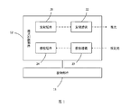
- FIG. 1 is a schematic structural diagram of a laser radar system provided by an embodiment of the present application.
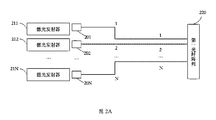
- 2A is a schematic structural diagram of a transmitting component of a laser radar system according to an embodiment of the present application
- 2B is a schematic structural diagram of another transmitting component of the laser radar system provided by the embodiment of the present application.
- FIG. 3 is a schematic structural view of a double cylindrical lens provided by an embodiment of the present application.
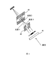
- FIG. 4 is a schematic structural diagram of a beam shaper based on optical diffraction according to an embodiment of the present application
- FIG. 5 is a schematic structural diagram of another optical diffraction-based beam shaper according to an embodiment of the present application.
- 6A is a schematic structural diagram of a receiving component of a laser radar system according to an embodiment of the present application.
- FIG. 6B is a schematic structural diagram of another receiving component of the laser radar system provided by the embodiment of the present application.
- the present embodiment provides a laser radar system including a rotating member 11 and a laser scanning member 12.
- the rotating member 11 is for rotating the laser scanning member 12.
- the rotating member 11 can cause the laser scanning unit 12 to perform a 360-degree rapid continuous rotation.
- the laser scanning section 12 described above includes a transmitting assembly 21, an emitting lens 22, a receiving lens 23, and a receiving assembly 24.
- the emission assembly of the laser scanning component 12 described above includes a plurality of laser emitters and a first fiber array.
- the transmitting assembly in this embodiment includes N laser emitters and a first fiber array 220.
- N is a natural number greater than or equal to 2.
- the N laser emitters are in one-to-one correspondence with the N optical fibers, wherein the laser light emitted by each laser emitter enters a corresponding optical fiber, and the optical transmission is performed through the optical fiber, and the N optical fibers correspond to the N optical fibers and the foregoing A fiber array 220 is connected. Specifically, as shown in FIG.
- the laser emitter 211, the laser emitter 212, the laser emitter 21N correspond to the optical fiber 1, the optical fiber 2, the optical fiber N, and the N optical fibers are connected to the first optical fiber array 220. Forming N light paths from the N laser emitters to the first fiber array 220.
- the transmitting component in the above embodiment may further include a multi-core optical fiber connector for connecting the plurality of optical fibers corresponding to the plurality of laser emitters to the first optical fiber array.
- the transmitting assembly further includes a first multi-core optical fiber connector 260, which will be a laser emitter 211, a laser emitter 212, ... a laser emitter.
- the 21N-corresponding fibers 1, 2, . . . N are connected to the first fiber array 220 to form N light paths from the N laser emitters to the first fiber array 220.
- the N lasers emitted by the N laser emitters of the transmitting component pass through the N optical paths to reach the first optical fiber array 220, and from the first optical fiber array 220.
- the end face is emitted, that is, the end face of the first fiber array 220 becomes the laser exit end of the transmitting assembly.
- the above-mentioned transmitting component further includes a plurality of beam shapers, and the plurality of beam shapers are in one-to-one correspondence with the plurality of laser emitters for coupling the laser light emitted by the laser emitter into the corresponding optical fiber.
- the beam assembly may include N beam shapers, such as beam shaper 201, beam shaper 202, ... beam shaper 20N, and the above N beam shapers and laser emitter 211, respectively.
- the laser emitters 212, ... the laser emitters 21N are in one-to-one correspondence for respectively coupling the laser beams emitted by the N laser emitters into the corresponding N optical fibers.
- the above beam shaper has various implementations, which are illustrated below.
- the beam shaper may be a double cylinder lens as shown in FIG. 3, and the bus bars of the two cylinders of the double cylinder lens are orthogonal to each other, that is, the bus bar L1 of the cylinder A of the double cylinder lens.
- the bus bars L2 of the cylinder B are orthogonal to each other.
- the high-power pulsed laser diode commonly used in multi-line laser radar is an edge emitting laser diode (Edge Emitting Laser Diode), and its illumination source is the end face of the chip P/N junction (PN Junction), that is, the P/N junction is at the intersection of two planes. Slit.
- the characteristics of such a laser emitter are: parallel to the plane of the P/N junction plane, the linear size of the beam is large (eg 50 um to hundreds of um), the divergence angle is small (eg 10 degrees); perpendicular to the P/N junction In the direction of the plane, the linear size of the beam is small (for example, 1um-10um), and the divergence angle is large (for example, 45 degrees).
- a direction with a large linear size and a small divergence angle is called a slow axis (Slow Axis); a direction with a small linear size and a large divergence angle is called a fast axis (Fast Axis).
- the double cylindrical lens shown in FIG. 3 used in this embodiment constitutes two independent optical systems for the fast axis and the slow axis of the laser beam, respectively.
- the laser light emitted by the laser emitter passes through the double cylindrical lens, and the divergence angle of the fast axis is decreased, and the divergence angle of the slow axis is increased, thereby achieving equalization and closeness of the divergence angle of the light beam between the fast axis and the slow axis. Therefore, the double cylindrical lens used in the embodiment can shape an elliptical spot with a large difference between the fast axis and the slow axis into a circular or square shape with less difference between the fast axis and the slow axis. A spot that allows the beam to be efficiently coupled into the fiber.
- the beam shaper may also be an optical diffraction-based beam shaper, as shown in FIG. 4, comprising: a collimating lens 41, a first diffractive element 42, and a second diffractive element 43.
- the collimating lens 41 described above is used to collimate the light beam emitted by the laser emitter in the fast axis direction to turn the beam into an elongated strip beam.
- the collimating lens 41 can be a micro cylindrical mirror.
- the first diffractive element 42 is used to split the elongated strip beam into a plurality of beams, and the beams are deflected to different spatial orientations except for the center beam.
- the second diffractive element 43 is configured to correct the remaining beams to overlap the remaining beams with the center beam and focus on the end faces of the corresponding fibers.
- the laser beam passes through the collimating lens 41 and becomes an elongated strip beam, which is divided into three beams by the first diffractive element 42: beam 1, beam 2 (center beam And beam 3, beam 1 is deflected downwards and to the right; beam 2 is the central beam, maintaining a direction of propagation parallel to the optical axis of the system; beam 3 is deflected upwards and to the left.
- the second diffractive element 43 corrects the beam 1 and the beam 3 such that the beam 1 and the beam 3 overlap with the central beam 2, forming a square spot having a relatively uniform linear dimension and divergence angle in both the fast axis and the slow axis, and Focus on the end face of the corresponding fiber.
- the optical diffraction-based beam shaper described above enables the beam to be efficiently coupled into the corresponding fiber.
- the beam shaper may be another optical diffraction-based beam shaper, as shown in FIG. 5, including: a first lens 51, a first diffraction element 52, a second diffraction element 53 and The second lens 54.
- the first lens 51 serves to collimate the light beam emitted from the laser emitter in the fast axis direction to become an elongated strip beam.
- the first lens 51 may be a micro cylindrical mirror.
- the first diffractive element 52 is used to split the elongated strip beam into a plurality of beams, and the beams are deflected to different spatial orientations except for the center beam.
- the second diffractive element 53 is for correcting the remaining beams to make the remaining beams parallel to the central beam.
- the second lens 54 is for superimposing and focusing the remaining light beams from the second diffraction element 53 and the center beam on the end faces of the corresponding fibers.
- the laser beam passes through the collimating lens 51 and becomes an elongated strip beam, which is divided into three beams by the first diffractive element 52: beam 1, beam 2 (center beam And beam 3, beam 1 is deflected downwards and to the right; beam 2 is the central beam, maintaining a direction of propagation parallel to the optical axis of the system; beam 3 is deflected upwards and to the left.
- the second diffractive element 53 corrects the beam 1 and the beam 3 such that the beam 1 and the beam 3 are parallel to the central beam 2.
- the second lens 54 overlaps the parallel beam 1, the beam 2, and the beam 3 to form a square spot having a relatively uniform linear dimension and a divergence angle in both the fast axis and the slow axis, and is focused to the end face of the corresponding fiber.
- the optical diffraction-based beam shaper described above enables the beam to be efficiently coupled into the fiber.
- the transmitting lens 22 of the laser radar system provided in this embodiment is used for collimating and emitting laser light from the first optical fiber array 220.
- the above-mentioned transmitting lens 22 receives the laser light from the plurality of laser emitters from the first optical fiber array 220, and after collimating, forms a fan-shaped laser beam array to be irradiated onto the target object.
- the first optical fiber array 220 is a one-dimensional optical fiber array or a two-dimensional optical fiber array.
- the end face of the first optical fiber array 220 is on the focal plane of the above-mentioned emitting lens 22.
- the receiving component of the laser scanning component 12 described above in the embodiment of the present application includes a plurality of receivers and a second fiber array.
- the receiving component in this embodiment includes N receivers and a second fiber array 240.
- N is a natural number greater than or equal to 2.
- the N receivers are in one-to-one correspondence with the N fibers, wherein each receiver receives the reflected light transmitted by the corresponding fiber, and the N fibers corresponding to the N receivers are connected to the second fiber array 240.
- the receiver 23N are in one-to-one correspondence with the optical fibers 1, the optical fibers 2, ..., the optical fibers N, and the N optical fibers are connected to the second optical fiber array 240 to form a second Two optical arrays 240 to N receivers to N optical paths.
- the receiving component in the above embodiment may further include a multi-core optical fiber connector for connecting a plurality of optical fibers corresponding to the plurality of receivers to the second optical fiber array.
- the receiving component further includes a second multi-core optical fiber connector 270, which corresponds to the receiver 231, the receiver 232, ... the receiver 23N.
- Fiber 1 Fiber 2... Fiber N is coupled to second fiber array 240 to form N light paths from second fiber array 240 to N receivers.
- the receiving component further includes a plurality of microlenses, and the plurality of microlenses are in one-to-one correspondence with the plurality of receivers for concentrating the reflected light conducted by the optical fibers to the corresponding receiver.
- the receiving assembly includes N microlenses, such as a microlens 251, a microlens 252, ..., a microlens 25N, and the above N microlenses are respectively connected to the receiver 231, the receiver 232, ...
- the receivers 23N are in one-to-one correspondence.
- the receiving lens 23 in the embodiment of the present application is configured to receive the reflected light of the laser light and converge the reflected light to the second optical fiber array 240 as shown in FIG. 6A or 6B, that is, the end surface of the second optical fiber array 240 becomes the laser of the receiving component. Incident end.
- the receiving lens 23 receives the light reflected by the target object, that is, the reflected light, which is the reflected light of the N laser beams emitted from the first optical fiber array 220 as shown in FIG. 2A or 2B. After the reflected light is concentrated by the receiving lens 23, it reaches the end surface of the second optical fiber array 240 as shown in FIG. 6A or 6B, and passes through N optical paths to reach N receivers.
- the fan-shaped laser beam array emitted by the transmitting lens 21 is reflected by the target object, and the reflected light still enters the receiving lens 23 in a fan-shaped array and is focused to enter the second optical fiber array 240.
- the second optical fiber array 240 is a one-dimensional optical fiber array or a two-dimensional optical fiber array.
- the end face of the second optical fiber array 240 is on the focal plane of the receiving lens 23.
- the laser radar system provided by the embodiment of the present application has a total of N laser ranging channels.
- the embodiment of the present application further provides a laser ranging method, which uses the laser radar system provided in the foregoing embodiment to perform laser ranging.
- the specific structure and working process of the laser radar system are as described in the above embodiments. I won't go into details here.
- the exit end of the laser and the incident end of the reflected light are both The end face of the fiber array, therefore, as long as the fiber array of the transmitting component is mounted on the focal plane of the transmitting lens and the fiber array of the receiving component is mounted on the focal plane of the receiving lens, the arrangement of the laser emitter and the receiver is not The limits of the transmit and receive angles are placed anywhere in the laser scanning component.
- the optical fiber array when the optical fiber array is used as the exit end of the laser in the transmitting component and the incident end of the laser in the incident component, only one small aperture lens window is needed for the transmitting end and the receiving end. It can realize tens of channels of multi-line laser radar. In summary, the volume of the mechanical rotary laser radar can be reduced by the technical solution provided by the embodiment.
- the optical fiber array is used as the laser output end of the transmitting component and the laser incident end of the receiving component, the relative angular positions of the plurality of laser ranging channels are accurately fixed. Therefore, no matter how many laser ranging channels are provided in the laser radar system provided in this embodiment, only two laser ranging channels need to be arbitrarily selected for focusing and optical axis alignment, so that precise focusing and light of all the other laser ranging channels can be realized.
- the axis alignment eliminates the need to adjust all the laser ranging channels one by one, and does not need to adjust the angular intervals of adjacent paths one by one, which greatly improves the assembly and adjustment efficiency of the multi-line laser radar and reduces the production cost.
- the transmitting component of the laser radar system provided by the embodiment shown in FIG. 2B and the receiving component of the laser radar system provided by the embodiment shown in FIG. 6B are connected to the optical fiber array by using a multi-core optical fiber connector to enable the laser
- the fiber array of the transmitter and the transmitting component is a relatively independent module
- the fiber array of the receiver and the receiving component is also a relatively independent module. Therefore, disassembling and repairing the laser emitter or receiver does not affect the layout and position of the fiber array. After the maintenance work is completed, it is not necessary to re-focus the laser ranging channel and the optical axis alignment work, which reduces the maintenance cost of the laser radar.
Landscapes
- Engineering & Computer Science (AREA)
- Physics & Mathematics (AREA)
- General Physics & Mathematics (AREA)
- Computer Networks & Wireless Communication (AREA)
- Radar, Positioning & Navigation (AREA)
- Remote Sensing (AREA)
- Electromagnetism (AREA)
- Optics & Photonics (AREA)
- Optical Radar Systems And Details Thereof (AREA)
- Optical Couplings Of Light Guides (AREA)
Abstract
一种激光雷达系统和激光测距方法。激光雷达系统包括:激光扫描部件(12)和旋转部件(11);激光扫描部件(12)包含发射组件(21)、发射透镜(22)、接收透镜(23)和接收组件(24)。发射组件(21)包含多个激光发射器(211,212,21N)和第一光纤阵列(220),接收组件(24)包含多个接收器(231,232,23N)和第二光纤阵列(240)。通过将光纤阵列作为发射组件的激光发射端和接收组件的发射光入射端,可减小激光雷达的体积,降低生产和调校成本。
Description
本申请要求于2018年04月11日提交中国专利局、申请号为201810321882.X、发明名称为“一种激光雷达系统和激光测距方法”的中国专利申请的优先权,其全部内容通过引用结合在本申请中。
本申请涉及激光探测和测距技术领域,尤其涉及一种激光雷达系统和激光测距方法。
激光探测和测距(Light Detection And Ranging,LiDAR)系统通常被称为激光雷达系统。激光雷达的基本工作原理是激光发射器发射激光到目标物体,接收器接收目标物体的发射光,激光雷达根据激光测距原理计算从激光雷达到目标物体的距离。其中,一个激光发射器和一个接收器组成一个激光测距通道。当激光对目标物体不断地扫描,可获得该目标物体上全部目标点的数据,对该数据进行成像处理后可得到该目标物体的三维立体图像。
常见的三维激光雷达是机械旋转式激光雷达,其包含多对激光发射器和接收器,每对激光发射器和接收器朝向不同的空间角度位置,形成扇面覆盖,然后用单轴旋转机构,驱动上述多对激光发射器和接收器整体旋转,实现三维激光扫描。
由于上述机械旋转式激光雷达的激光发射器和接收器的数量多、尺寸大,因此相邻激光测距通道间存在较大的物理间距,从而导致整个激光雷达的尺寸较大、角分辨率较低。同时,由于每个激光测距通道的激光发射器和接收器都需要进行精确校准,以保证对焦准确、发射和接收光轴精确平行,且需要保证相邻激光测距通道之间微小而精确的角度间隔,使得这类激光雷达组装和调校的工作量大、生产效率低,从而导致很高的生产成本。另外,当各激光测距通道的调校工作完成后,需要将所有激光发射器和接收器胶合固定,因此,一旦出现某个或某几个激光测距通道损坏时,需要对所有激光测距通道重新进行组装和调校,维修成本极大。
发明内容
有鉴于此,本申请实施例提供一种激光雷达系统,包含:激光扫描部件和旋转部件,上述旋转部件用于旋转上述激光扫描部件;上述激光扫描部件包含:发射组件、发射透镜、接收组件和接收透镜。进一步地,上述发射组件包含多个激光发射器和第一光纤阵列,上述多个激光发射器与多条光纤一一对应,其中每个激光发射器发射的激光进入对应的光纤,上述多个激光发射器对应的多条光纤与上述第一光纤阵列连接;上述发射透镜用于将来自上述第一光纤阵列的激光准直后发射;上述接收组件包含多个接收器和第二光纤阵列,上述多个接收器与多条光纤一一对应,其中每个接收器接收对应光纤传导的反射光,上述多个接收器对应的多条光纤与上述第二光纤阵列连接;上述接收透镜用于接收上述激光的反射光,并将该反射光汇聚到上述第二光纤阵列。
可选地,上述发射组件还包含第一多芯光纤连接器,用于将上述多个激光发射器对应的多条光纤连接到上述第一光纤阵列;上述接收组件还包含第二多芯光纤连接器,用于将上述多个接收器对应的多条光纤连接到上述第二光纤阵列。
进一步地,上述发射组件还包含多个光束整形器,上述多个光束整形器与上述多个激光发射器一一对应,上述光束整形器用于将激光发射器发射的激光耦合到对应的光纤中。可选地,上述光束整形器可以是双柱面透镜,该双柱面透镜的两个柱面的母线相互正交。
或者,上述光束整形器可以是一种基于光学衍射的光束整形器,包括:准直透镜、第一衍射元件和第二衍射元件。其中,上述准直透镜用于将激光发射器发射的光束在快轴方向进行准直,变成细长条形光束;上述第一衍射元件用于将上述细长条形光束分成若干光束,除中心光束外,其余各光束分别偏转向不同的空间方位;上述第二衍射元件用于对上述其余各光束进行校正,使上述其余各光束与上述中心光束重叠,并聚焦到对应光纤的端面。
或者,上述光束整形器还可以是另一种基于光学衍射的光束整形器,包括:第一透镜、第一衍射元件、第二衍射元件和第二透镜。其中,上述第一透镜用于将上述激光发射器发射的光束在快轴方向进行准直,变成细长条形光束;上述第一衍射元件用于将上述细长条形光束分成若干光束,除中心光束外,其余各光束分别偏转向不同的空间方位;上述第二衍射元件用于对上述其余各光束进行校正,使上述其余各光束与上述中心光束平行;上述第二透镜用于将来自上述第二衍射元件的上述其余各光束和上述中心光束重叠,并聚焦到对应光纤的端面。
进一步地,上述接收组件还可以包含多个微透镜,上述多个微透镜与多个接收器一一对应,用于将光纤传导的反射光汇聚到对应的接收器。
进一步地,上述第一光纤阵列的端面在上述发射透镜的焦平面上,上述第二光纤阵列的端面在上述接收透镜的焦平面上。可选地,上述第一光纤阵列可以是一维光纤阵列或二维光纤阵列;上述第二光纤阵列可以是一维光纤阵列或二维光纤阵列。
本申请实施例还提供一种激光测距方法,该方法使用激光雷达系统进行激光测距,该激光雷达系统包含激光扫描部件和旋转部件;上述激光扫描部件包含发射组件、发射透镜、接收组件和接收透镜;上述发射组件包含多个激光发射器和第一光纤阵列,上述多个激光发射器与多条光纤一一对应,上述多个激光发射器对应的多条光纤与上述第一光纤阵列连接;上述接收组件包含多个接收器和第二光纤阵列,上述多个接收器与多条光纤一一对应,上述多个接收器对应的多条光纤与上述第二光纤阵列连接。上述旋转部件旋转上述激光扫描部件;上述多个激光发射器发射激光,上述激光通过对应的光纤进行光传导,并从上述第一光纤阵列发射;上述发射透镜将来自上述第一光纤阵列的激光准直后发射;上述接收透镜接收上述激光的反射光,并将上述反射光汇聚到上述第二光纤阵列;上述多个接收器接收对应光纤传导的反射光。
可选地,上述发射组件还可以包含第一多芯光纤连接器,上述多个激光发射器对应的多条光纤与上述第一光纤阵列连接,包括:通过上述第一多芯光纤连接器将上述多个激光发射器对应的多条光纤连接到上述第一光纤阵列;上述接收组件还可以还包含第二多芯光纤连接器,上述多个接收器对应的多条光纤与上述第二光纤阵列连接,包括:通过上述第二多芯光纤连接器将上述多个接收器对应的多条光纤连接到上述第二光纤阵列。
进一步地,上述发射组件还包含多个光束整形器,上述多个光束整形器与上述多个激光发射器一一对应,上述光束整形器将激光发射器发射的激光耦合到对应的光纤中。可选地,上述光束整形器是双柱面透镜,上述双柱面透镜的两个柱面的母线相互正交。
或者,上述光束整形器还可以是一种基于光学衍射的光束整形器,包括:准直透镜、第一衍射元件和第二衍射元件。上述光束整形器将激光发射器发射的激光耦合到对应的光纤中,包含:上述准直透镜将上述激光发射器发射的光束在快轴方向进行准直,变成细长条形光束;上述第一衍射元件将上述细长条形光束分成若干光束,除中心光束外,其余各光束分别偏转向不同的空间方位;上述第二衍射元件对上述其余各光束进行校正,使上述其余各光束与上述中心光束重叠,并聚焦到对应光纤的端面。
或者,上述光束整形器还可以是另一种基于光学衍射的光束整形器,包括:第一透镜、第一衍射元件、第二衍射元件和第二透镜。上述光束整形器将激光发射器发射的激光耦合到对应的光纤中,包含:上述第一透镜将上述激光发射器发射的光束在快轴方向进行准直,变成细长条形光束;上述第一衍射元件将上述细长条形光束分成若干光束,除中心光束外,其余各光束分别偏转向不同的空间方位;上述第二衍射元件对上述其余各光束进行校正,使上述其余各光束与上述中心光束平行;上述第二透镜将来自上述第二衍射元件的上述其余各光束和上述中心光束重叠,并聚焦到对应光纤的端面。
进一步地,上述接收组件还可以包含多个微透镜,上述多个微透镜与上述多个接收器一一对应,上述微透镜将光纤传导的反射光汇聚到对应的接收器。
具体地,上述第一光纤阵列的端面在上述发射透镜的焦平面上,上述第二光纤阵列的端面在上述接收透镜的焦平面上。上述第一光纤阵列可以是一维光纤阵列或二维光纤阵列;上述第二光纤阵列可以是一维光纤阵列或二维光纤阵列。
本申请实施例提供的激光雷达系统和激光测距方法,通过使用光纤阵列作为发射组件的激光发射端和接收组件的反射光入射端,可以减小激光雷达的体积,降低生产和调校成本。另外,作为一个可选实施例,通过使用多芯光纤连接器将多个激光发射器和多个接收器连接到光纤阵列,可以实现激光雷达结构的模块化,从而降低激光雷达的维护成本。
为了清楚地说明本申请实施例提供的技术方案,下面将对实施例描述所需要使用的附图作简单介绍。显而易见地,下面描述的附图仅是本申请的一些实施例,对于本领域普通技术人员来讲,在不付出创造性劳动的前提下,还可以根据这些附图获得其他附图。
图1是本申请实施例提供的激光雷达系统的结构示意图;
图2A是本申请实施例提供的激光雷达系统的一种发射组件的结构示意图;
图2B是本申请实施例提供的激光雷达系统的另一种发射组件的结构示意图;
图3是本申请实施例提供的双柱面透镜的结构示意图;
图4是本申请实施例提供的一种基于光学衍射的光束整形器的结构示意图;
图5是本申请实施例提供的另一种基于光学衍射的光束整形器的结构示意图;
图6A是本申请实施例提供的激光雷达系统的一种接收组件的结构示意图;
图6B是本申请实施例提供的激光雷达系统的另一种接收组件的结构示意图。
下面将结合本申请实施例的附图,对本申请实施例的技术方案进行详细地描述,显然,以下所描述的实施例是本申请一部分实施例,而不是全部的实施例。基于以下实施例,本领域普通技术人员在没有作出创造性劳动前提下所获得的所有其他实施例,都属于本申请保护的范围。
如图1所示,本实施例提供一种激光雷达系统,包括旋转部件11和激光扫描部件12。上述旋转部件11用于旋转上述激光扫描部件12。具体地,该旋转部件11可以使上述激光扫描部件12进行360度快速连续旋转。上述激光扫描部件12包含发射组件21、发射透镜22、接收透镜23和接收组件24。
进一步地,上述激光扫描部件12的发射组件包含多个激光发射器和第一光纤阵列。如图2A所示,本实施例中的发射组件包含N个激光发射器和第一光纤阵列220。其中,N为大于等于2的自然数。上述N个激光发射器与N条光纤一一对应,其中每个激光发射器发射的激光进入对应的光纤,并通过该光纤进行光传导,上述N个激光发射器对应的N条光纤与上述第一光纤阵列220连接。具体地,如图2A所示,激光发射器211、激光发射器212、……激光发射器21N与光纤1、光纤2、…光纤N一一对应,该N条光纤与第一光纤阵列220连,形成从N个激光发射器到第一光纤阵列220的N条光通路。
作为另一种可选实施方案,上述实施例中的发射组件还可以包含一个多芯光纤连接器,用于将多个激光发射器对应的多条光纤连接到第一光纤阵列。如图2B所示,在图2A的基础上,发射组件还包含第一多芯光纤连接器260,该第一多芯光纤连接器件260将激光发射器211、激光发射器212……激光发射器21N对应的光纤1、2……N连接到第一光纤阵列220,形成从N个激光发射器到第一光纤阵列220的N条光通路。
在上述图2A或2B所示实施例提供的激光雷达系统中,发射组件的N个激光发射器发射的N条激光经过N条光通路到达第一光纤阵列220,并从第一光纤阵列220的端面发出,即第一光纤阵列220的端面成为发射组件的激光出射端。
作为一个优选实施例,上述发射组件还包含多个光束整形器,上述多个光束整形器与上述多个激光发射器一一对应,用于将激光发射器发射的激光耦合到对应的光纤中。如图2A或2B所示,发射组件中可以包含N个光束整形器,例如光束整形器201、光束整形器202、……光束整形器20N,并且上述N个光束整形器分别与激光发射器211、激光发射器212、……激光发射器21N一一对应,用于将上述N个激光发射器发射的激光分别耦合到对应的N条 光纤中。上述光束整形器有多种实现方式,现举例说明如下。
作为一个可选方案,上述光束整形器可以是图3所示的双柱面透镜,该双柱面透镜的两个柱面的母线相互正交,即双柱面透镜的柱面A的母线L1和柱面B的母线L2相互正交。
多线激光雷达常用的高功率脉冲激光二极管是边发射半导体激光二极管(Edge Emitting Laser Diode),其发光源是芯片P/N结(P-N Junction)的端面,即P/N结两个平面交界的狭缝。这种激光发射器的特性是:平行于P/N结平面的方向,光束的线性尺寸较大(例如50um至数百um),发散角较小(例如10度);垂直于P/N结平面的方向,光束的线性尺寸较小(例如1um-10um),发散角较大(例如45度)。线性尺寸大、发散角小的方向,被称为慢轴(Slow Axis);线性尺寸小、发散角大的方向,被称为快轴(Fast Axis)。
本实施例采用的图3所示的双柱面透镜对激光光束的快轴和慢轴分别构成两个独立的光学系统。激光发射器发出的激光经过上述双柱面透镜,快轴的发散角减小、慢轴的发散角增加,从而实现光束在快轴和慢轴的发散角均衡、接近。因此,本实施例采用的双柱面透镜可以将快轴和慢轴两个方向差异性很大的椭圆形光斑,整形为快轴和慢轴两个方向的差异性较小的圆形或方形光斑,使光束高效耦合到光纤中。
作为另一个可选方案,上述光束整形器还可以是一种基于光学衍射的光束整形器,如图4所示,包括:准直透镜41、第一衍射元件42和第二衍射元件43。上述准直透镜41用于将激光发射器发射的光束在快轴方向进行准直,将光束变成细长条形光束。例如,该准直透镜41可以是微型柱面镜。第一衍射元件42用于将上述细长条形光束分成若干光束,除中心光束外,其余各光束分别偏转向不同的空间方位。第二衍射元件43用于对上述其余各光束进行校正,使上述其余各光束与中心光束重叠,并聚焦到对应光纤的端面。
具体地,如图4所示,激光光束经过准直透镜41后变成细长条形光束,该细长条形光束被第一衍射元件42分成3个光束:光束1、光束2(中心光束)和光束3,光束1向下、向右偏转;光束2是中心光束,保持与系统光轴平行的传播方向;光束3向上、向左偏转。第二衍射元件43对光束1和光束3进行校正,使上述光束1和光束3与中心光束2重叠,形成快轴和慢轴两个方向的线性尺寸和发散角都相对均衡的方形光斑,并聚焦到对应光纤的端面。上述基于光学衍射的光束整形器可以使光束高效地耦合到对应光纤中。
作为再一个可选方案,上述光束整形器还可以是另一种基于光学衍射的光束整形器,如图5所示,包括:第一透镜51、第一衍射元件52、第二衍射元件53和第二透镜54。第一透镜51用于将激光发射器发射的光束在快轴方向进行准直,变成细长条形光束。例如,该第一 透镜51可以是微型柱面镜。第一衍射元件52用于将上述细长条形光束分成若干光束,除中心光束外,其余各光束分别偏转向不同的空间方位。第二衍射元件53用于对上述其余各光束进行校正,使上述其余各光束与上述中心光束平行。第二透镜54用于将来自上述第二衍射元件53的上述其余各光束和上述中心光束重叠并聚焦到对应光纤的端面。
具体地,如图5所示,激光光束经过准直透镜51后变成细长条形光束,该细长条形光束被第一衍射元件52分成3个光束:光束1、光束2(中心光束)和光束3,光束1向下、向右偏转;光束2是中心光束,保持与系统光轴平行的传播方向;光束3向上、向左偏转。第二衍射元件53对光束1和光束3进行校正,使上述光束1和光束3与中心光束2平行。第二透镜54将平行的光束1、光束2和光束3重叠,形成快轴和慢轴两个方向的线性尺寸和发散角都相对均衡的方形光斑,并聚焦到对应光纤的端面。上述基于光学衍射的光束整形器可以使光束高效地耦合到光纤中。
本实施例提供的激光雷达系统的发射透镜22用于将来自上述第一光纤阵列220的激光准直后发射。例如,上述发射透镜22从上述第一光纤阵列220接收来自上述多个激光发射器的激光,准直后,形成一个扇形分布的激光束阵列,照射到目标物体上。
可选地,上述第一光纤阵列220是一维光纤阵列或二维光纤阵列。上述第一光纤阵列220的端面在上述发射透镜22的焦平面上。
本申请实施例中上述激光扫描部件12的接收组件包含多个接收器和第二光纤阵列。如图6A所示,本实施例中的接收组件包含N个接收器和第二光纤阵列240。其中,N为大于等于2的自然数。上述N个接收器与N条光纤一一对应,其中每个接收器接收对应光纤传导的反射光,上述N个接收器对应的N条光纤与上述第二光纤阵列240连接。具体地,如图6A所示,接收器231、接收器232、…接收器23N与光纤1、光纤2、…光纤N一一对应,该N条光纤与第二光纤阵列240连接,形成从第二光纤阵列240到N个接收器到的N条光通路。
作为另一种可选实施方案,上述实施例中的接收组件还可以包含一个多芯光纤连接器,用于将多个接收器对应的多条光纤连接到第二光纤阵列。如图6B所示,在图6A的基础上,接收组件还包含第二多芯光纤连接器270,该第二多芯光纤连接器件270将接收器231、接收器232……接收器23N对应的光纤1、光纤2…光纤N连接到第二光纤阵列240,形成从第二光纤阵列240到N个接收器到的N条光通路。
作为一个优选实施例,上述接收组件还包含多个微透镜,上述多个微透镜与多个接收器一一对应,用于将光纤传导的反射光汇聚到对应的接收器。如图6A或6B所示,接收组件中 包含N个微透镜,例如微透镜251、微透镜252、……微透镜25N,并且上述N个微透镜分别与接收器231、接收器232、……接收器23N一一对应。
本申请实施例中的接收透镜23用于接收激光的反射光,并将反射光汇聚到如图6A或6B所示的第二光纤阵列240,即第二光纤阵列240的端面成为接收组件的激光入射端。例如,接收透镜23接收经目标物体反射的光,即反射光,该反射光是如图2A或2B所示的第一个光纤阵列220发射出的N条激光的反射光。上述反射光经接收透镜23汇聚后,到达如图6A或6B所示的第二光纤阵列240的端面,并经过N条光通路到达N个接收器。根据光路可逆性,由发射透镜21发射出的扇形分布的激光束阵列,经目标物体反射后,反射光仍成扇形阵列到达接收透镜23并被聚焦,进入第二光纤阵列240。
可选地,上述第二光纤阵列240是一维光纤阵列或二维光纤阵列。上述第二光纤阵列240的端面在上述接收透镜23的焦平面上。
本申请实施例提供的激光雷达系统中,一个激光发射器和对应的一个接收器,组成一个激光测距通道。因此,本申请实施例提供的激光雷达系统共有N个激光测距通道。
本申请实施例还提供一种激光测距方法,该激光测距方法使用前述实施例提供的激光雷达系统进行激光测距,该激光雷达系统的具体结构和工作过程如上述实施例所述,此处不再赘述。
本申请实施例提供的激光雷达系统,由于所有激光发射器到发射透镜、接收透镜到接收器的光通路都是通过纤细、柔软的光纤连接,并且激光的出射端和反射光的入射端都是光纤阵列的端面,因此,只要将发射组件的光纤阵列安装在发射透镜的焦平面上、将接收组件的光纤阵列安装在接收透镜的焦平面上,激光发射器和接收器的排列就可以不受发射和接收角度的限制,布局在激光扫描部件的任何位置。同时,由于光纤阵列尺寸小、光纤集成度高,因此,将光纤阵列作为发射组件中激光的出射端和入射组件中激光的入射端时,发射端和接收端仅各需要一个小口径的透镜窗口,就可实现数十通道的多线激光雷达。综上所述,通过本实施例提供的技术方案,可以减小机械旋转式激光雷达的体积。
另一方面,本申请实施例提供的激光雷达系统,由于采用了光纤阵列作为发射组件的激光出射端和接收组件的激光入射端,实现了多个激光测距通道的相对角度位置精确地固定。因此,无论本实施例提供的激光雷达系统有多少个激光测距通道,仅需任意选取两个激光测距通道进行对焦和光轴对准工作,即可实现其余所有激光测距通道的精准对焦和光轴对准, 不需要对所有激光测距通道进行逐一调校,也无须对相邻通路的角度间隔进行逐一调整,极大地提升了多线激光雷达的组装和调校效率,降低了生产成本。
此外,如图2B所示实施例提供的激光雷达系统的发射组件和如图6B所示实施例提供的激光雷达系统的接收组件,由于使用多芯光纤连接器将光纤连接到光纤阵列,使激光发射器与发射组件的光纤阵列是相对独立的模块,接收器与接收组件的光纤阵列也是相对独立的模块,因此,拆解、检修激光发射器或接收器不会影响光纤阵列的布局和位置,检修工作完成后不需要重新进行激光测距通道的对焦和光轴对准工作,降低了激光雷达的检修成本。
以上实施例和附图仅为本申请技术方案的示例性说明,并非用于限定本申请的保护范围。凡在本申请的精神和原则之内,所作的任何修改、等同替换、改进等,均应包含在本申请的保护范围之内。
Claims (18)
- 一种激光雷达系统,其特征在于,包含:激光扫描部件和旋转部件;所述旋转部件,用于旋转所述激光扫描部件;所述激光扫描部件,进一步包含:发射组件,包含多个激光发射器和第一光纤阵列,所述多个激光发射器与多条光纤一一对应,其中每个激光发射器发射的激光进入对应的光纤,所述多个激光发射器对应的多条光纤与所述第一光纤阵列连接;发射透镜,用于将来自所述第一光纤阵列的激光准直后发射;接收组件,包含多个接收器和第二光纤阵列,所述多个接收器与多条光纤一一对应,其中每个接收器接收对应光纤传导的反射光,所述多个接收器对应的多条光纤与所述第二光纤阵列连接;和接收透镜,用于接收所述激光的反射光,并将所述反射光汇聚到所述第二光纤阵列。
- 根据权利要求1所述的激光雷达系统,其特征在于,所述发射组件还包含第一多芯光纤连接器,用于将所述多个激光发射器对应的多条光纤连接到所述第一光纤阵列;所述接收组件还包含第二多芯光纤连接器,用于将所述多个接收器对应的多条光纤连接到所述第二光纤阵列。
- 根据权利要求1或2所述的激光雷达系统,其特征在于,所述发射组件还包含多个光束整形器,所述多个光束整形器与所述多个激光发射器一一对应,所述光束整形器用于将激光发射器发射的激光耦合到对应的光纤中。
- 根据权利要求3所述的激光雷达系统,其特征在于,所述光束整形器是双柱面透镜,所述双柱面透镜的两个柱面的母线相互正交。
- 根据权利要求3所述的激光雷达系统,其特征在于,所述光束整形器是基于光学衍射的光束整形器,包括:准直透镜、第一衍射元件和第二衍射元件;所述准直透镜,用于将所述激光发射器发射的光束在快轴方向进行准直,变成细长条形光束;所述第一衍射元件,用于将所述细长条形光束分成若干光束,除中心光束外,其余各光束分别偏转向不同的空间方位;所述第二衍射元件,用于对所述其余各光束进行校正,使所述其余各光束与所述中心光束重叠,并聚焦到对应光纤的端面。
- 根据权利要求3所述的激光雷达系统,其特征在于,所述光束整形器是基于光学衍射的光束整形器,包括:第一透镜、第一衍射元件、第二衍射元件和第二透镜;所述第一透镜,用于将所述激光发射器发射的光束在快轴方向进行准直,变成细长条形光束;所述第一衍射元件,用于将所述细长条形光束分成若干光束,除中心光束外,其余各光束分别偏转向不同的空间方位;所述第二衍射元件,用于对所述其余各光束进行校正,使所述其余各光束与所述中心光束平行;所述第二透镜,用于将来自所述第二衍射元件的所述其余各光束和所述中心光束重叠,并聚焦到对应光纤的端面。
- 根据权利要求1或2所述的激光雷达系统,其特征在于,所述接收组件还包含多个微透镜,所述多个微透镜与所述多个接收器一一对应,用于将光纤传导的反射光汇聚到对应的接收器。
- 根据权利要求1或2所述的激光雷达系统,其特征在于,所述第一光纤阵列的端面在所述发射透镜的焦平面上,所述第二光纤阵列的端面在所述接收透镜的焦平面上。
- 根据权利要求1或2所述的激光雷达系统,其特征在于,所述第一光纤阵列是一维光纤阵列或二维光纤阵列;所述第二光纤阵列是一维光纤阵列或二维光纤阵列。
- 一种激光测距方法,其特征在于,使用激光雷达系统进行激光测距,所述激光雷达系统包含激光扫描部件和旋转部件;所述激光扫描部件包含发射组件、发射透镜、接收组件和接收透镜;所述发射组件包含多个激光发射器和第一光纤阵列,所述多个激光发射器与多条光纤一一对应,所述多个激光发射器对应的多条光纤与所述第一光纤阵列连接;所述接收组件包含多个接收器和第二光纤阵列,所述多个接收器与多条光纤一一对应,所述多个接收器对应的多条光纤与所述第二光纤阵列连接;所述旋转部件旋转所述激光扫描部件;所述多个激光发射器发射激光,所述激光通过对应的光纤进行光传导,并从所述第一光纤阵列发射;所述发射透镜将来自所述第一光纤阵列的激光准直后发射;所述接收透镜接收所述激光的反射光,并将所述反射光汇聚到所述第二光纤阵列;所述多个接收器接收对应光纤传导的反射光。
- 根据权利要求10所述的激光测距方法,其特征在于,所述发射组件还包含第一多芯光纤连接器,所述多个激光发射器对应的多条光纤与所述第一光纤阵列连接,包括:通过所述第一多芯光纤连接器将所述多个激光发射器对应的多条光纤连接到所述第一光纤阵列;所述接收组件还包含第二多芯光纤连接器,所述多个接收器对应的多条光纤与所述第二光纤阵列连接,包括:通过所述第二多芯光纤连接器将所述多个接收器对应的多条光纤连接到所述第二光纤阵列。
- 根据权利要求10或11所述的激光测距方法,其特征在于,所述发射组件还包含多个光束整形器,所述多个光束整形器与所述多个激光发射器一一对应,所述光束整形器将激光发射器发射的激光耦合到对应的光纤中。
- 根据权利要求12所述的激光测距方法,其特征在于,所述光束整形器是双柱面透镜,所述双柱面透镜的两个柱面的母线相互正交。
- 根据权利要求12所述的激光测距方法,其特征在于,所述光束整形器是基于光学衍射的光束整形器,包括:准直透镜、第一衍射元件和第二衍射元件;所述光束整形器将激光发射器发射的激光耦合到对应的光纤中,包含:所述准直透镜将所述激光发射器发射的光束在快轴方向进行准直,变成细长条形光束;所述第一衍射元件将所述细长条形光束分成若干光束,除中心光束外,其余各光束分别偏转向不同的空间方位;所述第二衍射元件对所述其余各光束进行校正,使所述其余各光束与所述中心光束重叠,并聚焦到对应光纤的端面。
- 根据权利要求12所述的激光测距方法,其特征在于,所述光束整形器是基于光学衍射的光束整形器,包括:第一透镜、第一衍射元件、第二衍射元件和第二透镜;所述光束整形器将激光发射器发射的激光耦合到对应的光纤中,包含:所述第一透镜将所述激光发射器发射的光束在快轴方向进行准直,变成细长条形光束;所述第一衍射元件将所述细长条形光束分成若干光束,除中心光束外,其余各光束分别偏转向不同的空间方位;所述第二衍射元件对所述其余各光束进行校正,使所述其余各光束与所述中心光束平行;所述第二透镜将来自所述第二衍射元件的所述其余各光束和所述中心光束重叠,并聚焦到对应光纤的端面。
- 根据权利要求10或11所述的激光测距方法,其特征在于,所述接收组件还包含多个微透镜,所述多个微透镜与所述多个接收器一一对应,所述微透镜将光纤传导的反射光汇聚到对应的接收器。
- 根据权利要求10或11所述的激光测距方法,其特征在于,所述第一光纤阵列的端面在所述发射透镜的焦平面上,所述第二光纤阵列的端面在所述接收透镜的焦平面上。
- 根据权利要求10或11所述的激光测距方法,其特征在于,所述第一光纤阵列是一维光纤阵列或二维光纤阵列;所述第二光纤阵列是一维光纤阵列或二维光纤阵列。
Priority Applications (3)
| Application Number | Priority Date | Filing Date | Title |
|---|---|---|---|
| EP18803522.4A EP3572842A4 (en) | 2018-04-11 | 2018-04-24 | LIGHT DETECTION AND REMOVAL MEASUREMENT SYSTEM AND LASER REMOVAL MEASUREMENT METHOD |
| JP2018564827A JP2021517957A (ja) | 2018-04-11 | 2018-04-24 | レーザーレーダーシステム及びレーザー測距方法 |
| US16/191,530 US20190317195A1 (en) | 2018-04-11 | 2018-11-15 | Lidar system and laser ranging method |
Applications Claiming Priority (2)
| Application Number | Priority Date | Filing Date | Title |
|---|---|---|---|
| CN201810321882.X | 2018-04-11 | ||
| CN201810321882.XA CN110361747A (zh) | 2018-04-11 | 2018-04-11 | 一种激光雷达系统和激光测距方法 |
Related Child Applications (1)
| Application Number | Title | Priority Date | Filing Date |
|---|---|---|---|
| US16/191,530 Continuation US20190317195A1 (en) | 2018-04-11 | 2018-11-15 | Lidar system and laser ranging method |
Publications (1)
| Publication Number | Publication Date |
|---|---|
| WO2019196135A1 true WO2019196135A1 (zh) | 2019-10-17 |
Family
ID=65493780
Family Applications (1)
| Application Number | Title | Priority Date | Filing Date |
|---|---|---|---|
| PCT/CN2018/084241 Ceased WO2019196135A1 (zh) | 2018-04-11 | 2018-04-24 | 一种激光雷达系统和激光测距方法 |
Country Status (5)
| Country | Link |
|---|---|
| US (1) | US20190317195A1 (zh) |
| EP (1) | EP3572842A4 (zh) |
| JP (1) | JP2021517957A (zh) |
| CN (1) | CN110361747A (zh) |
| WO (1) | WO2019196135A1 (zh) |
Cited By (13)
| Publication number | Priority date | Publication date | Assignee | Title |
|---|---|---|---|---|
| CN113495258A (zh) * | 2020-04-07 | 2021-10-12 | 广东博智林机器人有限公司 | 激光雷达测试装置及激光雷达的测试方法 |
| US11460576B2 (en) * | 2019-04-18 | 2022-10-04 | Beijing Voyager Technology Co., Ltd. | Transmitter having beam shifter for light detection and ranging (LIDAR) |
| US11536805B2 (en) * | 2018-06-25 | 2022-12-27 | Silc Technologies, Inc. | Optical switching for tuning direction of LIDAR output signals |
| US11703598B2 (en) | 2019-11-18 | 2023-07-18 | Silc Technologies, Inc. | Steering of LIDAR output signals |
| US12405378B2 (en) | 2019-06-28 | 2025-09-02 | Silc Technologies, Inc. | Use of frequency offsets in generation of LIDAR data |
| US12411213B2 (en) | 2021-10-11 | 2025-09-09 | Silc Technologies, Inc. | Separation of light signals in a LIDAR system |
| US12422618B2 (en) | 2022-10-13 | 2025-09-23 | Silc Technologies, Inc. | Buried taper with reflecting surface |
| US12429569B2 (en) | 2019-05-17 | 2025-09-30 | Silc Technologies, Inc. | Identification of materials illuminated by LIDAR systems |
| US12535586B2 (en) | 2018-08-31 | 2026-01-27 | SiLC Technology, Inc. | Reduction of ADC sampling rates in LIDAR systems |
| US12541009B2 (en) | 2021-06-17 | 2026-02-03 | Silc Technologies, Inc. | Scanning multiple LIDAR system output signals |
| US12553995B2 (en) | 2022-02-14 | 2026-02-17 | Silc Technologies, Inc. | Data refinement in optical systems |
| US12578443B2 (en) | 2022-04-23 | 2026-03-17 | Silc Technologies, Inc. | Data refinement in optical imaging systems |
| US12578439B2 (en) | 2023-04-11 | 2026-03-17 | Silc Technologies, Inc. | Increasing resolution in imaging systems |
Families Citing this family (9)
| Publication number | Priority date | Publication date | Assignee | Title |
|---|---|---|---|---|
| KR102739949B1 (ko) * | 2018-07-05 | 2024-12-06 | 삼성전자주식회사 | 광센싱 시스템 및 이를 포함하는 전자 기기 |
| CN111487639B (zh) * | 2020-04-20 | 2024-05-03 | 深圳奥锐达科技有限公司 | 一种激光测距装置及方法 |
| US12601816B2 (en) * | 2020-05-13 | 2026-04-14 | National Instruments Corporation | System for emulating an environment for testing a frequency modulated continuous wave (FMCW) light detection and ranging (LiDAR) system |
| CN111669226B (zh) * | 2020-06-12 | 2022-04-05 | 青岛镭创光电技术有限公司 | 一种全光纤式激光发射接收系统 |
| US12553992B2 (en) | 2020-12-31 | 2026-02-17 | DSCG Solutions, Inc. | Multiple-beam lidar using a zoom lens |
| JP2024503309A (ja) * | 2020-12-31 | 2024-01-25 | ディーエスシージー ソルーションズ,インコーポレイテッド | ズームレンズを用いたマルチビームlidar |
| US20230081599A1 (en) * | 2021-09-15 | 2023-03-16 | Rosemount Aerospace Inc. | Multi-fiber optical sensor for light aircraft |
| CN114415190B (zh) * | 2021-12-30 | 2025-07-15 | 图达通智能科技(苏州)有限公司 | 一种激光雷达的收发装置 |
| CN115399681B (zh) * | 2022-09-19 | 2024-04-05 | 上海集成电路制造创新中心有限公司 | 传感器、机器人和扫地机 |
Citations (8)
| Publication number | Priority date | Publication date | Assignee | Title |
|---|---|---|---|---|
| WO1987007942A1 (fr) * | 1986-06-18 | 1987-12-30 | Bertin & Cie | Dispositif opto-electronique pour la determination de la distance et de la forme d'un objet |
| EP0603826A1 (en) * | 1992-12-21 | 1994-06-29 | Kabushiki Kaisha Topcon | Optical distance meter |
| CN1925032A (zh) * | 2005-09-02 | 2007-03-07 | 鸿富锦精密工业(深圳)有限公司 | 光学模组及采用所述光学模组的光学记录/再现装置 |
| CN203688802U (zh) * | 2014-01-11 | 2014-07-02 | 桂林理工大学 | 一种n×n阵列激光雷达装置 |
| CN106371085A (zh) * | 2016-10-27 | 2017-02-01 | 上海博未传感技术有限公司 | 一种基于光纤阵列的激光雷达系统 |
| CN107153195A (zh) * | 2016-12-30 | 2017-09-12 | 深圳市速腾聚创科技有限公司 | 多线激光雷达和多线激光雷达控制方法 |
| CN208188336U (zh) * | 2018-04-11 | 2018-12-04 | 无锡流深光电科技有限公司 | 一种激光雷达系统 |
| CN208188335U (zh) * | 2018-04-04 | 2018-12-04 | 无锡流深光电科技有限公司 | 一种激光雷达系统 |
Family Cites Families (3)
| Publication number | Priority date | Publication date | Assignee | Title |
|---|---|---|---|---|
| JP3607211B2 (ja) * | 2001-03-13 | 2005-01-05 | 株式会社東芝 | 光導波路、光モジュール、光ファイバレーザ装置 |
| US6952510B1 (en) * | 2001-08-31 | 2005-10-04 | Nlight Photonics Corporation | Optically corrected intracavity fiber coupled multigain element laser |
| US7515346B2 (en) * | 2006-07-18 | 2009-04-07 | Coherent, Inc. | High power and high brightness diode-laser array for material processing applications |
-
2018
- 2018-04-11 CN CN201810321882.XA patent/CN110361747A/zh active Pending
- 2018-04-24 JP JP2018564827A patent/JP2021517957A/ja active Pending
- 2018-04-24 EP EP18803522.4A patent/EP3572842A4/en not_active Withdrawn
- 2018-04-24 WO PCT/CN2018/084241 patent/WO2019196135A1/zh not_active Ceased
- 2018-11-15 US US16/191,530 patent/US20190317195A1/en not_active Abandoned
Patent Citations (8)
| Publication number | Priority date | Publication date | Assignee | Title |
|---|---|---|---|---|
| WO1987007942A1 (fr) * | 1986-06-18 | 1987-12-30 | Bertin & Cie | Dispositif opto-electronique pour la determination de la distance et de la forme d'un objet |
| EP0603826A1 (en) * | 1992-12-21 | 1994-06-29 | Kabushiki Kaisha Topcon | Optical distance meter |
| CN1925032A (zh) * | 2005-09-02 | 2007-03-07 | 鸿富锦精密工业(深圳)有限公司 | 光学模组及采用所述光学模组的光学记录/再现装置 |
| CN203688802U (zh) * | 2014-01-11 | 2014-07-02 | 桂林理工大学 | 一种n×n阵列激光雷达装置 |
| CN106371085A (zh) * | 2016-10-27 | 2017-02-01 | 上海博未传感技术有限公司 | 一种基于光纤阵列的激光雷达系统 |
| CN107153195A (zh) * | 2016-12-30 | 2017-09-12 | 深圳市速腾聚创科技有限公司 | 多线激光雷达和多线激光雷达控制方法 |
| CN208188335U (zh) * | 2018-04-04 | 2018-12-04 | 无锡流深光电科技有限公司 | 一种激光雷达系统 |
| CN208188336U (zh) * | 2018-04-11 | 2018-12-04 | 无锡流深光电科技有限公司 | 一种激光雷达系统 |
Non-Patent Citations (1)
| Title |
|---|
| See also references of EP3572842A4 * |
Cited By (14)
| Publication number | Priority date | Publication date | Assignee | Title |
|---|---|---|---|---|
| US11536805B2 (en) * | 2018-06-25 | 2022-12-27 | Silc Technologies, Inc. | Optical switching for tuning direction of LIDAR output signals |
| US12339399B2 (en) | 2018-06-25 | 2025-06-24 | Silc Technologies, Inc. | Optical switching for tuning direction of LIDAR output signals |
| US12535586B2 (en) | 2018-08-31 | 2026-01-27 | SiLC Technology, Inc. | Reduction of ADC sampling rates in LIDAR systems |
| US11460576B2 (en) * | 2019-04-18 | 2022-10-04 | Beijing Voyager Technology Co., Ltd. | Transmitter having beam shifter for light detection and ranging (LIDAR) |
| US12429569B2 (en) | 2019-05-17 | 2025-09-30 | Silc Technologies, Inc. | Identification of materials illuminated by LIDAR systems |
| US12405378B2 (en) | 2019-06-28 | 2025-09-02 | Silc Technologies, Inc. | Use of frequency offsets in generation of LIDAR data |
| US11703598B2 (en) | 2019-11-18 | 2023-07-18 | Silc Technologies, Inc. | Steering of LIDAR output signals |
| CN113495258A (zh) * | 2020-04-07 | 2021-10-12 | 广东博智林机器人有限公司 | 激光雷达测试装置及激光雷达的测试方法 |
| US12541009B2 (en) | 2021-06-17 | 2026-02-03 | Silc Technologies, Inc. | Scanning multiple LIDAR system output signals |
| US12411213B2 (en) | 2021-10-11 | 2025-09-09 | Silc Technologies, Inc. | Separation of light signals in a LIDAR system |
| US12553995B2 (en) | 2022-02-14 | 2026-02-17 | Silc Technologies, Inc. | Data refinement in optical systems |
| US12578443B2 (en) | 2022-04-23 | 2026-03-17 | Silc Technologies, Inc. | Data refinement in optical imaging systems |
| US12422618B2 (en) | 2022-10-13 | 2025-09-23 | Silc Technologies, Inc. | Buried taper with reflecting surface |
| US12578439B2 (en) | 2023-04-11 | 2026-03-17 | Silc Technologies, Inc. | Increasing resolution in imaging systems |
Also Published As
| Publication number | Publication date |
|---|---|
| US20190317195A1 (en) | 2019-10-17 |
| EP3572842A1 (en) | 2019-11-27 |
| JP2021517957A (ja) | 2021-07-29 |
| CN110361747A (zh) | 2019-10-22 |
| EP3572842A4 (en) | 2019-11-27 |
Similar Documents
| Publication | Publication Date | Title |
|---|---|---|
| CN110361747A (zh) | 一种激光雷达系统和激光测距方法 | |
| CN208188335U (zh) | 一种激光雷达系统 | |
| WO2019192038A1 (zh) | 一种激光雷达系统和激光测距方法 | |
| CN109581400B (zh) | 一种分布式激光雷达系统和激光测距方法 | |
| US20250044419A1 (en) | VCSEL Array LIDAR Transmitter with Small Angular Divergence | |
| JP2023161035A5 (zh) | ||
| CN107688186B (zh) | 一种多线激光雷达光路系统 | |
| CN208188336U (zh) | 一种激光雷达系统 | |
| CN108490420A (zh) | 一种微镜扫描光学系统 | |
| CN110658509A (zh) | 基于一维衍射光学元件doe的激光雷达系统 | |
| CN105652452A (zh) | 一种空间合束装置和系统 | |
| US6292303B1 (en) | Laser apparatus for simultaneously generating a plurality of laser planes from a single laser source | |
| CN209055652U (zh) | 一种激光雷达扫描系统和激光雷达 | |
| KR101884781B1 (ko) | 3차원 스캐닝 시스템 | |
| KR101174322B1 (ko) | 레이저 어레이 | |
| CN107121781A (zh) | 光束整形装置 | |
| CN108375762A (zh) | 激光雷达及其工作方法 | |
| CN109444851B (zh) | 激光发射机构及相控阵激光雷达 | |
| CN110531371A (zh) | 一种激光雷达和激光测距方法 | |
| KR20190025115A (ko) | 회전형 스캐닝 라이다 | |
| CN209746129U (zh) | 一种分布式激光雷达系统 | |
| CN222232674U (zh) | 激光雷达 | |
| CN115047428A (zh) | 激光雷达 | |
| US11762066B2 (en) | Multi-beam scanning system | |
| US20250237747A1 (en) | Anamorphic beam transformation to match a lidar scanner |
Legal Events
| Date | Code | Title | Description |
|---|---|---|---|
| ENP | Entry into the national phase |
Ref document number: 2018564827 Country of ref document: JP Kind code of ref document: A |
|
| ENP | Entry into the national phase |
Ref document number: 2018803522 Country of ref document: EP Effective date: 20181127 |
|
| 121 | Ep: the epo has been informed by wipo that ep was designated in this application |
Ref document number: 18803522 Country of ref document: EP Kind code of ref document: A1 |
|
| NENP | Non-entry into the national phase |
Ref country code: DE |