WO2019198196A1 - 暖房システム - Google Patents
暖房システム Download PDFInfo
- Publication number
- WO2019198196A1 WO2019198196A1 PCT/JP2018/015371 JP2018015371W WO2019198196A1 WO 2019198196 A1 WO2019198196 A1 WO 2019198196A1 JP 2018015371 W JP2018015371 W JP 2018015371W WO 2019198196 A1 WO2019198196 A1 WO 2019198196A1
- Authority
- WO
- WIPO (PCT)
- Prior art keywords
- heating
- passage
- fluid
- heat source
- switching valve
- Prior art date
- Legal status (The legal status is an assumption and is not a legal conclusion. Google has not performed a legal analysis and makes no representation as to the accuracy of the status listed.)
- Ceased
Links
Images



Classifications
-
- F—MECHANICAL ENGINEERING; LIGHTING; HEATING; WEAPONS; BLASTING
- F24—HEATING; RANGES; VENTILATING
- F24D—DOMESTIC- OR SPACE-HEATING SYSTEMS, e.g. CENTRAL HEATING SYSTEMS; DOMESTIC HOT-WATER SUPPLY SYSTEMS; ELEMENTS OR COMPONENTS THEREFOR
- F24D3/00—Hot-water central heating systems
- F24D3/18—Hot-water central heating systems using heat pumps
-
- F—MECHANICAL ENGINEERING; LIGHTING; HEATING; WEAPONS; BLASTING
- F24—HEATING; RANGES; VENTILATING
- F24D—DOMESTIC- OR SPACE-HEATING SYSTEMS, e.g. CENTRAL HEATING SYSTEMS; DOMESTIC HOT-WATER SUPPLY SYSTEMS; ELEMENTS OR COMPONENTS THEREFOR
- F24D11/00—Central heating systems using heat accumulated in storage masses
- F24D11/02—Central heating systems using heat accumulated in storage masses using heat pumps
- F24D11/0214—Central heating systems using heat accumulated in storage masses using heat pumps water heating system
-
- F—MECHANICAL ENGINEERING; LIGHTING; HEATING; WEAPONS; BLASTING
- F24—HEATING; RANGES; VENTILATING
- F24D—DOMESTIC- OR SPACE-HEATING SYSTEMS, e.g. CENTRAL HEATING SYSTEMS; DOMESTIC HOT-WATER SUPPLY SYSTEMS; ELEMENTS OR COMPONENTS THEREFOR
- F24D19/00—Details
- F24D19/10—Arrangement or mounting of control or safety devices
- F24D19/1006—Arrangement or mounting of control or safety devices for water heating systems
- F24D19/1009—Arrangement or mounting of control or safety devices for water heating systems for central heating
- F24D19/1015—Arrangement or mounting of control or safety devices for water heating systems for central heating using a valve or valves
- F24D19/1024—Arrangement or mounting of control or safety devices for water heating systems for central heating using a valve or valves a multiple way valve
-
- F—MECHANICAL ENGINEERING; LIGHTING; HEATING; WEAPONS; BLASTING
- F24—HEATING; RANGES; VENTILATING
- F24D—DOMESTIC- OR SPACE-HEATING SYSTEMS, e.g. CENTRAL HEATING SYSTEMS; DOMESTIC HOT-WATER SUPPLY SYSTEMS; ELEMENTS OR COMPONENTS THEREFOR
- F24D19/00—Details
- F24D19/10—Arrangement or mounting of control or safety devices
- F24D19/1006—Arrangement or mounting of control or safety devices for water heating systems
- F24D19/1009—Arrangement or mounting of control or safety devices for water heating systems for central heating
- F24D19/1039—Arrangement or mounting of control or safety devices for water heating systems for central heating the system uses a heat pump
-
- F—MECHANICAL ENGINEERING; LIGHTING; HEATING; WEAPONS; BLASTING
- F24—HEATING; RANGES; VENTILATING
- F24D—DOMESTIC- OR SPACE-HEATING SYSTEMS, e.g. CENTRAL HEATING SYSTEMS; DOMESTIC HOT-WATER SUPPLY SYSTEMS; ELEMENTS OR COMPONENTS THEREFOR
- F24D2200/00—Heat sources or energy sources
- F24D2200/12—Heat pump
- F24D2200/123—Compression type heat pumps
-
- F—MECHANICAL ENGINEERING; LIGHTING; HEATING; WEAPONS; BLASTING
- F24—HEATING; RANGES; VENTILATING
- F24D—DOMESTIC- OR SPACE-HEATING SYSTEMS, e.g. CENTRAL HEATING SYSTEMS; DOMESTIC HOT-WATER SUPPLY SYSTEMS; ELEMENTS OR COMPONENTS THEREFOR
- F24D2220/00—Components of central heating installations excluding heat sources
- F24D2220/02—Fluid distribution means
- F24D2220/0242—Multiple way valves
-
- F—MECHANICAL ENGINEERING; LIGHTING; HEATING; WEAPONS; BLASTING
- F24—HEATING; RANGES; VENTILATING
- F24D—DOMESTIC- OR SPACE-HEATING SYSTEMS, e.g. CENTRAL HEATING SYSTEMS; DOMESTIC HOT-WATER SUPPLY SYSTEMS; ELEMENTS OR COMPONENTS THEREFOR
- F24D2220/00—Components of central heating installations excluding heat sources
- F24D2220/08—Storage tanks
-
- Y—GENERAL TAGGING OF NEW TECHNOLOGICAL DEVELOPMENTS; GENERAL TAGGING OF CROSS-SECTIONAL TECHNOLOGIES SPANNING OVER SEVERAL SECTIONS OF THE IPC; TECHNICAL SUBJECTS COVERED BY FORMER USPC CROSS-REFERENCE ART COLLECTIONS [XRACs] AND DIGESTS
- Y02—TECHNOLOGIES OR APPLICATIONS FOR MITIGATION OR ADAPTATION AGAINST CLIMATE CHANGE
- Y02B—CLIMATE CHANGE MITIGATION TECHNOLOGIES RELATED TO BUILDINGS, e.g. HOUSING, HOUSE APPLIANCES OR RELATED END-USER APPLICATIONS
- Y02B30/00—Energy efficient heating, ventilation or air conditioning [HVAC]
- Y02B30/12—Hot water central heating systems using heat pumps
Definitions
- the present invention relates to a heating system.
- a heating system that performs a heating operation and a heat storage operation for storing heat in a tank using a high-temperature fluid generated by a heat pump or other heat source device is known.
- Patent Document 1 discloses a hot water heating and hot water supply apparatus that can perform a heating operation and a heat storage operation using a heat source, a storage tank, seven switching valves, and one pump.
- Patent Document 1 since a large number of actuators are required, the control of the switching valve becomes complicated, the power consumption increases, the product cost increases, and the product weight increases.
- the present invention has been made to solve the above-described problems, and an object thereof is to provide a heating system that is advantageous for simplifying the device configuration.
- a heating system of the present invention has a tank for storing fluid, an inlet and an outlet, a heat source for heating the fluid, a pump having an inlet and an outlet, and circulating the fluid, an outlet of the pump, A first passage having a first passage connecting between an inlet of a heat source, a second passage connecting between a fluid outlet of the heating device and a suction port of the pump, a first port, a second port, and a third port A third passage connecting between the switching valve, the second switching valve having the fourth port, the fifth port, and the sixth port, the first branch portion formed in the middle of the first passage, and the first port A second passage formed in the middle of the second passage, a fourth passage connecting the second port, a fifth passage connecting the lower portion of the tank and the third port, and a heat source Between the sixth passage connecting the exit and the fourth port, the upper part of the tank, and the fifth port And a control means for controlling the operation of the heat source, the pump, the first switching valve, and the second switching valve.
- the first switching valve switches between the third-fifth communication in which the third passage communicates with the fifth passage and the fourth-fifth communication in which the fourth passage communicates with the fifth passage.
- the second switching valve is capable of connecting the sixth passage to the seventh passage in which the sixth passage communicates with the seventh passage and the sixth to eighth passage in which the sixth passage communicates with the eighth passage.
- the seventh passage which is in a state where the seventh passage communicates with the eighth passage, and the sixth, seventh, eighth, where both the sixth passage and the seventh passage communicate with the eighth passage. It can be switched to communication.
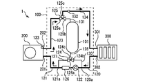
- FIG. It is a figure which shows the heating system by Embodiment 1.
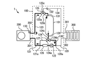
- FIG. It is a figure which shows the flow of the fluid at the time of the heat source heating operation of the heating system shown in FIG. It is a figure which shows the flow of the fluid at the time of the tank heating operation of the heating system shown in FIG. It is a figure which shows the flow of the fluid at the time of the mixing heating operation of the heating system shown in FIG. It is a figure which shows the flow of the fluid at the time of the thermal storage driving
- FIG. 1 is a diagram illustrating a heating system according to the first embodiment.
- the heating system 1 includes a tank 101, a heat source 200, a pump 122, a first switching valve 124, a second switching valve 125, and a control device 150.
- the tank 101 corresponds to a heat storage tank that stores a fluid as a heat medium.
- the fluid may be water or a liquid other than water such as an aqueous calcium chloride solution, an aqueous ethylene glycol solution, or alcohol.
- a temperature stratification is formed in which the upper side is high temperature and the lower side is low temperature due to a difference in fluid density due to temperature difference.
- the tank 101 is covered with a heat insulating material (not shown).
- the tank 101 is not limited to a single tank as illustrated, and may include a plurality of tanks connected in series.
- the height direction in the tank 101 that is, the position in the vertical direction will be referred to.
- the tank 101 includes a plurality of tanks connected in series via pipes, In the entire hierarchy up to the lowest tank, the vertical position is specified.
- the heat source 200 can heat the fluid.
- the heat source 200 has an inlet 201 and an outlet 202.
- the fluid entering from the inlet 201 is heated inside the heat source 200.
- the heated fluid flows out from the outlet 202.
- the heat source 200 may include at least one of a heat pump, a boiler, and an electric heater, for example.
- the pump 122 circulates fluid.
- the pump 122 has a suction port and a discharge port.
- the first passage 121 connects the discharge port of the pump 122 and the inlet 201 of the heat source 200.
- the heating device 300 includes a fluid inlet 301 and a fluid outlet 302.
- the heating device 300 warms the room by dissipating the heat of the fluid.
- the heating device 300 may include, for example, at least one of a floor heating panel installed under the floor, a radiator installed on an indoor wall surface, a panel heater, and a fan convector.
- a plurality of heating devices 300 may be connected.
- the connection method when a plurality of heating devices 300 are connected may be any of a combination of series, parallel, series, and parallel.
- the second passage 120 connects between the fluid outlet 302 of the heating device 300 and the suction port of the pump 122.
- the first switching valve 124 has a first port 124a, a second port 124b, and a third port 124c.
- the second switching valve 125 has a fourth port 125a, a fifth port 125b, and a sixth port 125c.
- a first branch part 121 a is formed in the middle of the first passage 121.
- the third passage 127 connects the first branch part 121a and the first port 124a.
- a second branch portion 120 a is formed in the middle of the second passage 120.
- the fourth passage 130 connects between the second branch part 120a and the second port 124b.
- the fifth passage 128 connects the lower portion of the tank 101 and the third port 124c.
- the sixth passage 123 connects the outlet 202 of the heat source 200 and the fourth port 125a.
- the seventh passage 131 connects between the upper part of the tank 101 and the fifth port 125b.
- the eighth passage 134 connects between the sixth port 125 c and the fluid inlet 301 of the heating device 300.
- the control device 150 is electrically connected to each of the heat source 200, the pump 122, the first switching valve 124, and the second switching valve 125, and controls these operations. In addition, sensors described later are electrically connected to the control device 150.
- the first switching valve 124 can be switched between “third-fifth communication” and “fourth-fifth communication”.
- the third-fifth communication is a state in which the third passage 127 communicates with the fifth passage 128 and the fourth passage 130 is blocked.
- the fourth-fifth communication is a state where the fourth passage 130 communicates with the fifth passage 128 and the third passage 127 is blocked.
- the second switching valve 125 can be switched between “sixth-seventh communication”, “sixth-eighth communication”, “seventh-eighth communication”, and “sixth-seventh-eighth communication”. is there.
- the sixth-seventh communication is a state where the sixth passage 123 communicates with the seventh passage 131 and the eighth passage 134 is blocked.
- the sixth-eight communication is a state where the sixth passage 123 communicates with the eighth passage 134 and the seventh passage 131 is blocked.
- the seventh-eight communication is a state where the seventh passage 131 communicates with the eighth passage 134 and the sixth passage 123 is blocked.
- the sixth-seventh-eighth communication is a state where both the sixth passage 123 and the seventh passage 131 communicate with the eighth passage 134.
- the heating system 1 of the present embodiment includes a remote controller 400.
- the control device 150 and the remote controller 400 are connected so as to be able to perform data communication in both directions by wire or wireless.
- the remote control 400 may be installed in a room.
- the remote controller 400 has a function of accepting a user operation related to a driving operation command, a change of a set value, and the like.
- the remote control 400 is an example of a user interface. Although illustration is omitted, the remote controller 400 may be equipped with a display for displaying information such as the status of the heating system 1, an operation unit such as a switch operated by the user, a speaker, a microphone, and the like.
- the heating system 1 may include a plurality of remote controllers 400 installed at different places.
- the heating system 1 of the present embodiment includes a flow rate sensor 126, a supply temperature sensor 132, and a post-heating temperature sensor 133.
- the flow sensor 126 detects the volume flow rate of the fluid passing through the pump 122.
- the flow sensor 126 is disposed in the first passage 121 between the first branch part 121a and the pump 122, but as a modification, the second sensor between the second branch part 120a and the pump 122 is provided.
- a flow sensor 126 may be disposed in the passage 120.
- the temperature of the fluid supplied to the heating device 300 is referred to as “supply temperature”.
- a supply temperature sensor 132 disposed in the eighth passage 134 detects the supply temperature.
- the post-heating temperature sensor 133 detects the post-heating temperature.
- the post-heating temperature sensor 133 is disposed at the outlet 202 of the heat source 200, but as a modification, the post-heating temperature sensor 133 may be disposed in the middle of the sixth passage 123.
- the control device 150 can adjust the heating capacity of the heat source 200.
- the heating capacity of the heat source 200 is the amount of heat that the heat source 200 gives to the fluid per hour.
- the unit of the heating capacity of the heat source 200 is “watts”, for example.
- the control device 150 can adjust the output and rotation speed of the pump 122.
- the control device 150 can adjust the flow rate of the circulating fluid by adjusting the output or rotation speed of the pump 122.
- the pump 122 may include a pulse width modulation control type DC motor whose rotation speed can be changed by a speed command voltage from the control device 150.
- the heating system 1 can perform a heat source heating operation, a tank heating operation, and a mixed heating operation.
- FIG. 2 is a diagram illustrating the flow of fluid during the heat source heating operation of the heating system 1 illustrated in FIG. 1. 2 and the subsequent drawings, the illustration of the control device 150 and the remote controller 400 is omitted.
- the control device 150 controls as follows.
- the first switching valve 124 is in the third-fifth communication.
- the second switching valve 125 is in sixth-eighth communication.
- the pump 122 and the heat source 200 are operated.
- the fluid heated in the heat source 200 is supplied to the heating device 300 through the sixth passage 123, the second switching valve 125, and the eighth passage 134.
- the fluid that has passed through the heating device 300 returns to the heat source 200 through the second passage 120, the pump 122, and the first passage 121.
- the flow rate of the fluid flowing through the heat source 200 is equal to the flow rate of the fluid flowing through the heating device 300.
- a heat pump type heat source 200 using a CO 2 refrigerant when used, a higher difference between the temperature of the fluid entering the heat source 200 and the temperature of the fluid exiting the heat source 200 results in higher efficiency operation. It has been known. For this reason, it becomes a highly efficient driving
- control device 150 may adjust at least one of the heating capability of the heat source 200 and the output of the pump 122 so that the supply temperature detected by the supply temperature sensor 132 becomes equal to the target value.
- the supply temperature can be easily and appropriately controlled.
- the target value of the supply temperature may be a value set by the user using the remote controller 400.
- FIG. 3 is a diagram showing the flow of fluid during the tank heating operation of the heating system 1 shown in FIG.
- the control device 150 controls as follows.
- the first switching valve 124 is in the third-fifth communication.
- the second switching valve 125 is in the seventh to eighth communication.
- the pump 122 is operated.
- the heat source 200 is stopped.
- the high-temperature fluid flowing out from the upper part of the tank 101 is supplied to the heating device 300 through the seventh passage 131, the second switching valve 125, and the eighth passage 134.
- the fluid that has passed through the heating device 300 passes through the second passage 120, the pump 122, the first passage 121 upstream of the first branch portion 121a, the third passage 127, the first switching valve 124, and the fifth passage 128. , Flows into the lower part of the tank 101.
- a fluid having a relatively high temperature for example, 60 ° C. or more
- a relatively high flow rate for example, 10 L / min or more.
- FIG. 4 is a diagram showing the flow of fluid during the mixed heating operation of the heating system 1 shown in FIG.
- the control device 150 performs control as follows.
- the first switching valve 124 is in the third-fifth communication.
- the second switching valve 125 is in sixth-seventh-eighth communication.
- the pump 122 is operated.
- the heat source 200 may be operated or may not be operated.
- the fluid that has passed through the heat source 200 flows into the second switching valve 125 through the sixth passage 123.
- the high-temperature fluid that has flowed out of the upper portion of the tank 101 flows into the second switching valve 125 through the seventh passage 131.
- a mixed fluid obtained by mixing the fluid that has passed through the heat source 200 and the fluid that has flowed out of the upper portion of the tank 101 in the second switching valve 125 is supplied to the heating device 300 through the eighth passage 134.
- the fluid that flows out of the heating device 300 passes through the second passage 120 and the pump 122, and then branches into two flows at the first branch portion 121a.
- One flow returns to the heat source 200 through the first passage 121 as it is.
- the other flow passes through the third passage 127, the first switching valve 124, and the fifth passage 128 and flows into the lower portion of the tank 101.
- control device 150 may adjust the mixing ratio by the second switching valve 125 so that the supply temperature detected by the supply temperature sensor 132 becomes equal to the target value. By doing so, the supply temperature can be easily and appropriately controlled.
- the flow rate of the fluid flowing through the heat source 200 is lower than the flow rate of the fluid flowing through the heating device 300. Therefore, the flow rate of the fluid flowing to the heating device 300 (for example, 10 L / min) can be made relatively high while the flow rate of the fluid flowing to the heat source 200 (for example, 5 L / min) is relatively low. According to such a mixed heating operation, even when a heat pump type heat source 200 using a CO 2 refrigerant is used, a highly efficient operation can be performed, and the heating apparatus 300 can be operated at a high flow rate. For this reason, since the influence of the temperature nonuniformity of the heating apparatus 300 hardly occurs, it is suitable for use in floor heating or the like.
- the control device 150 may perform the mixed heating operation without operating the heat source 200. By doing so, heating operation can be performed with a relatively low heating capacity and a high flow rate.
- the control device 150 may perform the mixed heating operation with the operation of the heat source 200.
- the control device 150 has a high mixing ratio of the high-temperature fluid flowing out from the tank 101 through the seventh passage 131. As such, the mixing ratio by the second switching valve 125 may be adjusted.
- the heating system 1 includes a temperature sensor that detects the temperature of the fluid stored in the tank 101.
- the control device 150 prohibits the tank heating operation and performs the heat source heating operation or the mixed heating operation. By doing so, it can prevent more reliably that the fluid of the temperature higher than the target value of supply temperature flows into the heating apparatus 300.
- control device 150 may adjust the output of the pump 122 so that the flow rate of the fluid detected by the flow sensor 126 becomes equal to the target value. By doing so, even when the pressure loss of the heating pipe changes due to long-term use, the same heating capacity can be continuously supplied.
- control device 150 may adjust the output of the pump 122 so that the rotational speed of the pump 122 becomes equal to the target value in each heating operation. By doing so, even when the heating apparatus 300 is divided into a plurality of systems and the number of systems used changes, the heating capacity to each system can be kept constant. For example, the control device 150 controls the rotational speed of the pump 122 when the heating device 300 is used in one system to be lower than the rotational speed of the pump 122 when the heating device 300 is used in two systems. May be.
- the heating system 1 can perform a heat storage operation in which the fluid heated by the heat source 200 flows into the tank 101.
- FIG. 5 is a diagram illustrating the flow of fluid during the heat storage operation of the heating system 1 illustrated in FIG. 1.
- the control device 150 controls as follows.
- the first switching valve 124 is in the fourth-fifth communication.
- the second switching valve 125 is in sixth-seventh communication.
- the low-temperature fluid that has flowed out from the lower part of the tank 101 flows into the fifth passage 128, the first switching valve 124, the fourth passage 130, the second passage 120 downstream from the second branch 120a, the pump 122, and the first passage 121. And is sent to the heat source 200.
- the high-temperature fluid heated in the heat source 200 flows into the upper portion of the tank 101 through the sixth passage 123, the second switching valve 125, and the seventh passage 131. With such a heat storage operation, a high-temperature fluid is gradually stored in the tank 101 from the top to the bottom, and the amount of heat stored in the tank 101 increases.
- the control device 150 uses at least the heating capability of the heat source 200 and the output of the pump 122 so that the post-heating temperature detected by the post-heating temperature sensor 133 is equal to the target temperature of the fluid stored in the tank 101. Adjust one. Thereby, the temperature of the fluid stored in the tank 101 can be easily and appropriately controlled.
- the user may be able to select the heat storage operation, the heat source heating operation, the tank heating operation, and the mixed heating operation by operating the remote controller 400 by the user. By doing so, good usability can be obtained.
- the heat source heating operation is a heating operation using the heating capability of the heat source 200
- the tank heating operation is a heating operation using the heat storage of the tank 101
- the mixed heating operation is the heating capability of the heat source 200 and the tank. It is the heating operation which can use both the heat storage of 101.
- the above-described three types of heating operation can be performed with a simple device configuration in which the number of switching valves and the number of pumps are small. For this reason, according to this Embodiment, it becomes advantageous when providing the heating system 1 with low power consumption, low cost, and lightweight.
- Each function of the control device 150 may be realized by a processing circuit.
- the processing circuit of the control device 150 may include at least one processor 151 and at least one memory 152.
- each function of the control device 150 may be realized by software, firmware, or a combination of software and firmware.
- At least one of software and firmware may be described as a program.
- At least one of software and firmware may be stored in at least one memory 152.
- the at least one processor 151 may realize each function of the control device 150 by reading and executing a program stored in the at least one memory 152.
- the at least one memory 152 may include a nonvolatile or volatile semiconductor memory, a magnetic disk, or the like.
- Heating system 100 heat source, 101 tank, 120 second passage, 120a second branch, 121 first passage, 121a first branch, 122 pump, 123 sixth passage, 124 first switching valve, 124a first port , 124b 2nd port, 124c 3rd port, 125 2nd switching valve, 125a 4th port, 125b 5th port, 125c 6th port, 126 flow sensor, 127 3rd passage, 128 5th passage, 130 4th passage 131, seventh passage, 132 supply temperature sensor, 133 temperature sensor after heating, 134 eighth passage, 150 control device, 200 heat source, 201 inlet, 202 outlet, 300 heating equipment, 301 fluid inlet, 302 fluid outlet , 400 remote control
Landscapes
- Engineering & Computer Science (AREA)
- Physics & Mathematics (AREA)
- Thermal Sciences (AREA)
- Chemical & Material Sciences (AREA)
- Combustion & Propulsion (AREA)
- Mechanical Engineering (AREA)
- General Engineering & Computer Science (AREA)
- Steam Or Hot-Water Central Heating Systems (AREA)
- Heat-Pump Type And Storage Water Heaters (AREA)
Abstract
Description
図1は、実施の形態1による暖房システムを示す図である。図1に示すように、暖房システム1は、タンク101、熱源200、ポンプ122、第一切替弁124、第二切替弁125、及び制御装置150を備える。タンク101は、熱媒体としての流体を貯留する蓄熱槽に相当する。流体は、水でもよいし、例えば塩化カルシウム水溶液、エチレングリコール水溶液、アルコールのような水以外の液体でもよい。タンク101内では、温度の違いによる流体の密度の差により、上側が高温で下側が低温になる温度成層が形成される。タンク101は、図示しない断熱材により覆われている。
Claims (9)
- 流体を貯留するタンクと、
入口及び出口を有し、前記流体を加熱する熱源と、
吸入口及び吐出口を有し、前記流体を循環させるポンプと、
前記ポンプの前記吐出口と、前記熱源の前記入口との間をつなぐ第一通路と、
暖房機器の流体出口と、前記ポンプの前記吸入口との間をつなぐ第二通路と、
第一ポート、第二ポート、及び第三ポートを有する第一切替弁と、
第四ポート、第五ポート、及び第六ポートを有する第二切替弁と、
前記第一通路の途中に形成された第一分岐部と、前記第一ポートとの間をつなぐ第三通路と、
前記第二通路の途中に形成された第二分岐部と、前記第二ポートとの間をつなぐ第四通路と、
前記タンクの下部と、前記第三ポートとの間をつなぐ第五通路と、
前記熱源の前記出口と、前記第四ポートとの間をつなぐ第六通路と、
前記タンクの上部と、前記第五ポートとの間をつなぐ第七通路と、
前記第六ポートと、前記暖房機器の流体入口との間をつなぐ第八通路と、
前記熱源、前記ポンプ、前記第一切替弁、及び前記第二切替弁の動作を制御する制御手段とを備え、
前記第一切替弁は、前記第三通路が前記第五通路に連通する状態である第三-第五連通と、前記第四通路が前記第五通路に連通する状態である第四-第五連通とに切り替え可能であり、
前記第二切替弁は、前記第六通路が前記第七通路に連通する状態である第六-第七連通と、前記第六通路が前記第八通路に連通する状態である第六-第八連通と、前記第七通路が前記第八通路に連通する状態である第七-第八連通と、前記第六通路及び前記第七通路の双方が前記第八通路に連通する状態である第六-第七-第八連通とに切り替え可能である暖房システム。 - 熱源暖房運転と、タンク暖房運転と、混合暖房運転とを実行可能であり、
前記熱源暖房運転のときには、前記第二切替弁を前記第六-第八連通にすることにより、前記熱源を通過した前記流体が前記暖房機器へ供給され、
前記タンク暖房運転のときには、前記第一切替弁を前記第三-第五連通にするとともに前記第二切替弁を前記第七-第八連通にすることにより、前記タンクの前記上部から流出した前記流体が前記暖房機器へ供給され、
前記混合暖房運転のときには、前記第一切替弁を前記第三-第五連通にするとともに前記第二切替弁を前記第六-第七-第八連通にすることにより、前記熱源を通過した前記流体と前記タンクの前記上部から流出した前記流体との混合流体が前記暖房機器へ供給される請求項1に記載の暖房システム。 - 前記暖房機器へ供給される前記流体の温度である供給温度を検出する供給温度センサを備え、
前記熱源暖房運転のときには、前記制御手段は、前記供給温度が目標値に等しくなるように前記熱源の加熱能力と前記ポンプの出力との少なくとも一方を調整し、
前記混合暖房運転のときには、前記制御手段は、前記供給温度が目標値に等しくなるように前記第二切替弁による混合比を調整する請求項2に記載の暖房システム。 - 前記タンクに貯留された前記流体の温度が、前記暖房機器へ供給される前記流体の温度の目標値よりも高い場合には、前記制御手段は、前記タンク暖房運転を禁止する請求項2または請求項3に記載の暖房システム。
- 暖房を開始するときには、前記制御手段は、前記タンク暖房運転を実行する請求項2から請求項4のいずれか一項に記載の暖房システム。
- 前記熱源により加熱された前記流体を前記タンクに流入させる蓄熱運転と、前記熱源暖房運転と、前記タンク暖房運転と、前記混合暖房運転とを使用者が選択可能にするユーザーインターフェースを備える請求項2から請求項5のいずれか一項に記載の暖房システム。
- 前記ポンプを通る前記流体の流量を検出する流量センサを備え、
前記暖房機器へ前記流体を供給する場合に、前記制御手段は、前記流体の流量が目標値に等しくなるように前記ポンプの出力を調整する請求項1から請求項6のいずれか一項に記載の暖房システム。 - 前記暖房機器へ前記流体を供給する場合に、前記制御手段は、前記ポンプの回転速度が目標値に等しくなるように前記ポンプの出力を調整する請求項1から請求項6のいずれか一項に記載の暖房システム。
- 前記熱源から流出する前記流体の温度である加熱後温度を検出する加熱後温度センサを備え、
前記熱源により加熱された前記流体を前記タンクに流入させる蓄熱運転のときには、前記第一切替弁を前記第四-第五連通にするとともに前記第二切替弁を前記第六-第七連通とし、
前記蓄熱運転において、前記制御手段は、前記加熱後温度が目標値に等しくなるように前記熱源の加熱能力と前記ポンプの出力との少なくとも一方を調整する請求項1から請求項8のいずれか一項に記載の暖房システム。
Priority Applications (3)
| Application Number | Priority Date | Filing Date | Title |
|---|---|---|---|
| EP18914406.6A EP3779285A4 (en) | 2018-04-12 | 2018-04-12 | HEATING SYSTEM |
| PCT/JP2018/015371 WO2019198196A1 (ja) | 2018-04-12 | 2018-04-12 | 暖房システム |
| JP2020513012A JP6888738B2 (ja) | 2018-04-12 | 2018-04-12 | 暖房システム |
Applications Claiming Priority (1)
| Application Number | Priority Date | Filing Date | Title |
|---|---|---|---|
| PCT/JP2018/015371 WO2019198196A1 (ja) | 2018-04-12 | 2018-04-12 | 暖房システム |
Publications (1)
| Publication Number | Publication Date |
|---|---|
| WO2019198196A1 true WO2019198196A1 (ja) | 2019-10-17 |
Family
ID=68164240
Family Applications (1)
| Application Number | Title | Priority Date | Filing Date |
|---|---|---|---|
| PCT/JP2018/015371 Ceased WO2019198196A1 (ja) | 2018-04-12 | 2018-04-12 | 暖房システム |
Country Status (3)
| Country | Link |
|---|---|
| EP (1) | EP3779285A4 (ja) |
| JP (1) | JP6888738B2 (ja) |
| WO (1) | WO2019198196A1 (ja) |
Cited By (1)
| Publication number | Priority date | Publication date | Assignee | Title |
|---|---|---|---|---|
| CN112073830A (zh) * | 2020-09-15 | 2020-12-11 | 中通服咨询设计研究院有限公司 | 一种基于物联网的天线通信装置 |
Families Citing this family (1)
| Publication number | Priority date | Publication date | Assignee | Title |
|---|---|---|---|---|
| DE102022211372A1 (de) * | 2022-10-26 | 2024-05-02 | Robert Bosch Gesellschaft mit beschränkter Haftung | Verfahren zum Betrieb eines Kraftwärmemaschinensystems, Steuer- oder Regelvorrichtung und Kraftwärmemaschinensystem |
Citations (4)
| Publication number | Priority date | Publication date | Assignee | Title |
|---|---|---|---|---|
| JP2004278987A (ja) * | 2003-03-18 | 2004-10-07 | Matsushita Electric Ind Co Ltd | ヒートポンプ式給湯器 |
| JP2006343011A (ja) * | 2005-06-08 | 2006-12-21 | Matsushita Electric Ind Co Ltd | 給湯装置 |
| JP2007263399A (ja) * | 2006-03-27 | 2007-10-11 | Noritz Corp | 貯留型熱源装置 |
| JP2008232462A (ja) | 2007-03-16 | 2008-10-02 | Corona Corp | ヒートポンプ貯湯式給湯暖房装置 |
Family Cites Families (5)
| Publication number | Priority date | Publication date | Assignee | Title |
|---|---|---|---|---|
| JP2004218908A (ja) * | 2003-01-14 | 2004-08-05 | Matsushita Electric Ind Co Ltd | 給湯機 |
| JP5892120B2 (ja) * | 2013-08-02 | 2016-03-23 | 三菱電機株式会社 | 暖房給湯システム |
| JP6252685B2 (ja) * | 2014-09-26 | 2017-12-27 | 三菱電機株式会社 | 給湯暖房システム |
| JP2017032149A (ja) * | 2015-07-29 | 2017-02-09 | パナソニックIpマネジメント株式会社 | 温水暖房装置 |
| WO2017163305A1 (ja) * | 2016-03-22 | 2017-09-28 | 三菱電機株式会社 | 熱媒体循環システム |
-
2018
- 2018-04-12 EP EP18914406.6A patent/EP3779285A4/en not_active Withdrawn
- 2018-04-12 WO PCT/JP2018/015371 patent/WO2019198196A1/ja not_active Ceased
- 2018-04-12 JP JP2020513012A patent/JP6888738B2/ja active Active
Patent Citations (4)
| Publication number | Priority date | Publication date | Assignee | Title |
|---|---|---|---|---|
| JP2004278987A (ja) * | 2003-03-18 | 2004-10-07 | Matsushita Electric Ind Co Ltd | ヒートポンプ式給湯器 |
| JP2006343011A (ja) * | 2005-06-08 | 2006-12-21 | Matsushita Electric Ind Co Ltd | 給湯装置 |
| JP2007263399A (ja) * | 2006-03-27 | 2007-10-11 | Noritz Corp | 貯留型熱源装置 |
| JP2008232462A (ja) | 2007-03-16 | 2008-10-02 | Corona Corp | ヒートポンプ貯湯式給湯暖房装置 |
Non-Patent Citations (1)
| Title |
|---|
| See also references of EP3779285A4 |
Cited By (2)
| Publication number | Priority date | Publication date | Assignee | Title |
|---|---|---|---|---|
| CN112073830A (zh) * | 2020-09-15 | 2020-12-11 | 中通服咨询设计研究院有限公司 | 一种基于物联网的天线通信装置 |
| CN112073830B (zh) * | 2020-09-15 | 2024-01-26 | 中通服咨询设计研究院有限公司 | 一种基于物联网的天线通信装置 |
Also Published As
| Publication number | Publication date |
|---|---|
| EP3779285A4 (en) | 2021-04-21 |
| JPWO2019198196A1 (ja) | 2020-10-22 |
| EP3779285A1 (en) | 2021-02-17 |
| JP6888738B2 (ja) | 2021-06-16 |
Similar Documents
| Publication | Publication Date | Title |
|---|---|---|
| US20150108230A1 (en) | Multiple zone control system and method of operation | |
| JP5264365B2 (ja) | 冷却塔及び熱源機システム | |
| JP6645593B2 (ja) | 熱媒体循環システム | |
| JP5476835B2 (ja) | 空調システム | |
| JP6888738B2 (ja) | 暖房システム | |
| EP3540324B1 (en) | Heating medium circulation system | |
| JP6721116B2 (ja) | 熱媒循環システム | |
| CN108050582B (zh) | 热泵系统和热泵控制方法 | |
| JP5818584B2 (ja) | ガス熱源機 | |
| JP2016166718A (ja) | ヒートポンプ給湯暖房システム | |
| WO2016129072A1 (ja) | 熱供給システム | |
| EP3421900B1 (en) | Storage type hot water supplying system | |
| JP2019066138A (ja) | コージェネレーションシステム | |
| JP7310690B2 (ja) | 貯湯式給湯装置 | |
| EP3220061B1 (en) | Fluid circulation system | |
| JP6687156B2 (ja) | 熱媒体供給システム | |
| JP6421880B2 (ja) | 熱媒体循環システム | |
| KR101588535B1 (ko) | 저탕식 급탕장치 | |
| CN112944712B (zh) | 一种热泵系统及控制方法 | |
| WO2017158685A1 (ja) | 熱媒体循環システム | |
| JP5884645B2 (ja) | 貯湯式給湯機 | |
| JP4771781B2 (ja) | 暖房システム | |
| JP2015224850A (ja) | 貯湯式給湯機 | |
| JP7274896B2 (ja) | 暖房システム | |
| WO2017163305A1 (ja) | 熱媒体循環システム |
Legal Events
| Date | Code | Title | Description |
|---|---|---|---|
| 121 | Ep: the epo has been informed by wipo that ep was designated in this application |
Ref document number: 18914406 Country of ref document: EP Kind code of ref document: A1 |
|
| ENP | Entry into the national phase |
Ref document number: 2020513012 Country of ref document: JP Kind code of ref document: A |
|
| NENP | Non-entry into the national phase |
Ref country code: DE |
|
| WWE | Wipo information: entry into national phase |
Ref document number: 2018914406 Country of ref document: EP |
|
| ENP | Entry into the national phase |
Ref document number: 2018914406 Country of ref document: EP Effective date: 20201112 |