WO2019198451A1 - 回転電機及び回転電機を有する電動パワーステアリング装置 - Google Patents
回転電機及び回転電機を有する電動パワーステアリング装置 Download PDFInfo
- Publication number
- WO2019198451A1 WO2019198451A1 PCT/JP2019/011796 JP2019011796W WO2019198451A1 WO 2019198451 A1 WO2019198451 A1 WO 2019198451A1 JP 2019011796 W JP2019011796 W JP 2019011796W WO 2019198451 A1 WO2019198451 A1 WO 2019198451A1
- Authority
- WO
- WIPO (PCT)
- Prior art keywords
- stator
- magnetic interference
- coil unit
- system coil
- winding
- Prior art date
- Legal status (The legal status is an assumption and is not a legal conclusion. Google has not performed a legal analysis and makes no representation as to the accuracy of the status listed.)
- Ceased
Links
Images








Classifications
-
- H—ELECTRICITY
- H02—GENERATION; CONVERSION OR DISTRIBUTION OF ELECTRIC POWER
- H02K—DYNAMO-ELECTRIC MACHINES
- H02K16/00—Machines with more than one rotor or stator
- H02K16/04—Machines with one rotor and two stators
-
- H—ELECTRICITY
- H02—GENERATION; CONVERSION OR DISTRIBUTION OF ELECTRIC POWER
- H02K—DYNAMO-ELECTRIC MACHINES
- H02K1/00—Details of the magnetic circuit
- H02K1/06—Details of the magnetic circuit characterised by the shape, form or construction
- H02K1/12—Stationary parts of the magnetic circuit
- H02K1/16—Stator cores with slots for windings
- H02K1/165—Shape, form or location of the slots
-
- H—ELECTRICITY
- H02—GENERATION; CONVERSION OR DISTRIBUTION OF ELECTRIC POWER
- H02K—DYNAMO-ELECTRIC MACHINES
- H02K1/00—Details of the magnetic circuit
- H02K1/06—Details of the magnetic circuit characterised by the shape, form or construction
- H02K1/12—Stationary parts of the magnetic circuit
- H02K1/18—Means for mounting or fastening magnetic stationary parts on to, or to, the stator structures
-
- H—ELECTRICITY
- H02—GENERATION; CONVERSION OR DISTRIBUTION OF ELECTRIC POWER
- H02K—DYNAMO-ELECTRIC MACHINES
- H02K3/00—Details of windings
- H02K3/04—Windings characterised by the conductor shape, form or construction, e.g. with bar conductors
- H02K3/12—Windings characterised by the conductor shape, form or construction, e.g. with bar conductors arranged in slots
-
- H—ELECTRICITY
- H02—GENERATION; CONVERSION OR DISTRIBUTION OF ELECTRIC POWER
- H02K—DYNAMO-ELECTRIC MACHINES
- H02K3/00—Details of windings
- H02K3/04—Windings characterised by the conductor shape, form or construction, e.g. with bar conductors
- H02K3/18—Windings for salient poles
-
- H—ELECTRICITY
- H02—GENERATION; CONVERSION OR DISTRIBUTION OF ELECTRIC POWER
- H02P—CONTROL OR REGULATION OF ELECTRIC MOTORS, ELECTRIC GENERATORS OR DYNAMO-ELECTRIC CONVERTERS; CONTROLLING TRANSFORMERS, REACTORS OR CHOKE COILS
- H02P25/00—Arrangements or methods for the control of AC motors characterised by the kind of AC motor or by structural details
- H02P25/16—Arrangements or methods for the control of AC motors characterised by the kind of AC motor or by structural details characterised by the circuit arrangement or by the kind of wiring
- H02P25/22—Multiple windings; Windings for more than three phases
-
- H—ELECTRICITY
- H02—GENERATION; CONVERSION OR DISTRIBUTION OF ELECTRIC POWER
- H02K—DYNAMO-ELECTRIC MACHINES
- H02K11/00—Structural association of dynamo-electric machines with electric components or with devices for shielding, monitoring or protection
- H02K11/30—Structural association with control circuits or drive circuits
- H02K11/33—Drive circuits, e.g. power electronics
-
- H—ELECTRICITY
- H02—GENERATION; CONVERSION OR DISTRIBUTION OF ELECTRIC POWER
- H02K—DYNAMO-ELECTRIC MACHINES
- H02K21/00—Synchronous motors having permanent magnets; Synchronous generators having permanent magnets
- H02K21/12—Synchronous motors having permanent magnets; Synchronous generators having permanent magnets with stationary armatures and rotating magnets
- H02K21/14—Synchronous motors having permanent magnets; Synchronous generators having permanent magnets with stationary armatures and rotating magnets with magnets rotating within the armatures
- H02K21/16—Synchronous motors having permanent magnets; Synchronous generators having permanent magnets with stationary armatures and rotating magnets with magnets rotating within the armatures having annular armature cores with salient poles
-
- H—ELECTRICITY
- H02—GENERATION; CONVERSION OR DISTRIBUTION OF ELECTRIC POWER
- H02K—DYNAMO-ELECTRIC MACHINES
- H02K2213/00—Specific aspects, not otherwise provided for and not covered by codes H02K2201/00 - H02K2211/00
- H02K2213/06—Machines characterised by the presence of fail safe, back up, redundant or other similar emergency arrangements
-
- H—ELECTRICITY
- H02—GENERATION; CONVERSION OR DISTRIBUTION OF ELECTRIC POWER
- H02K—DYNAMO-ELECTRIC MACHINES
- H02K3/00—Details of windings
- H02K3/04—Windings characterised by the conductor shape, form or construction, e.g. with bar conductors
- H02K3/28—Layout of windings or of connections between windings
Definitions
- the present invention relates to a rotating electric machine having a plurality of winding groups and an electric power steering apparatus having the rotating electric machine.
- Patent Document 1 As in the rotating electrical machine described in Patent Document 1, there is known a rotating electrical machine in which a plurality of winding groups are wound around one tooth and a winding group through which a current flows is switched.
- This invention is made in order to solve such a subject, and when a plurality of winding groups are wound around one tooth, rotation capable of suppressing deterioration of controllability due to magnetic interference is provided.
- An object is to provide an electric power steering apparatus having an electric machine and a rotating electric machine.
- a rotating electrical machine is a rotating electrical machine including an annular stator, and the stator includes a core back portion and a plurality of radially extending inner portions from the core back portion. Teeth, a plurality of winding groups wound for each tooth, and a magnetic interference reducing member that is disposed between adjacent winding groups and reduces magnetic interference between the winding groups.
- the wire group is connected to a different power supply source for each winding group, and the winding group is separated from the other winding group in the radial direction or the circumferential direction of the stator by the magnetic interference reducing member.
- the rotating electrical machine according to the present invention includes a rotating electrical machine and a rotating electrical machine that can suppress deterioration of controllability due to magnetic interference when a plurality of winding groups are wound around one tooth.
- An electric power steering apparatus having the above can be obtained.
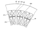
- FIG. 3 is a partially enlarged view of the stator shown in FIG. 2.
- FIG. 3 shows the stator and rotor for comparing with the stator and rotor of a rotary electric machine which concern on Embodiment 1 of this invention.
- It is the schematic which shows the magnetic path which passes along the stator shown in FIG. 5 is a graph for comparing torque and magnetic interference rate of the rotating electrical machine having the stator shown in FIG.
- the electric drive device 100 includes a rotating electrical machine 10, a first system power supply source 20, and a second system power supply source 30.
- the first system power supply source 20 and the second system power supply source 30 constitute independent inverter devices that apply a three-phase alternating current to the windings of the rotating electrical machine 10. That is, the rotating electrical machine 10 is a rotating electrical machine that is driven by two systems of three-phase AC power.
- the rotating electrical machine 10 is a permanent magnet type concentrated winding rotating electrical machine, and has a frame 11 that accommodates each component.
- the frame 11 is joined to the front housing 12 of the rotating electrical machine 10 with bolts (not shown).
- a stator 40 is disposed on the inner wall of the frame 11.
- the stator 40 includes a stator core 41 and a stator winding 42 that is wound around the stator core 41.
- the stator core 41 is configured by laminating core sheets formed of a magnetic material. This magnetic body may be, for example, an electromagnetic steel plate.
- the stator core 41 is an armature core
- the stator winding 42 is an armature winding.
- a rotor 50 formed to be rotatable is provided on the inner side in the radial direction with respect to the stator 40.
- the rotor 50 includes a rotor core 51 and a permanent magnet 52 attached to the rotor core 51.
- a shaft 14 is attached to the center of the rotor core 51.
- the shaft 14 is rotatably supported by a bearing 13a and a bearing 13b.
- the shaft 14 and the rotor 50 are provided to be rotatable with respect to the stator 40.
- a holder 15 attached to the end of the shaft 14 and a sensor magnet 16 held by the holder 15 and rotating at the same speed as the rotor 50 are provided.
- a first substrate 21 facing the sensor magnet 16 is provided.
- a semiconductor sensor 22 is mounted on the first substrate 21. The semiconductor sensor 22 detects the rotational speed of the rotor 50 by detecting the rotational speed of the sensor magnet 16.
- the electric drive device 100 is provided with a first system drive circuit 23 and a second system drive circuit 33.
- the first system drive circuit 23 is a drive circuit for applying a current to the first system winding of the stator winding 42.
- the second system drive circuit 33 is a drive circuit for applying a current to the second system winding of the stator winding 42.
- the first system drive circuit 23 and the second system drive circuit 33 are connected to the second substrate 24 by wiring 27.
- the semiconductor sensor 22 is connected to the second substrate 24 by a wiring 26.
- the second board 24 is provided with a first system control circuit 25 and a second system control circuit 35.
- the first system control circuit 25 is a control circuit for controlling the first system drive circuit 23.
- the second system control circuit 35 is a control circuit for controlling the second system drive circuit 33.
- the first system control circuit 25 and the second system control circuit 35 control the first system drive circuit 23 and the second system drive circuit 33 based on the information on the rotational speed of the rotor 50 detected by the semiconductor sensor 22.
- the first system control circuit 25 is connected to the first system connector 28, and the second system control circuit 35 is connected to the second system connector 38.
- the 1st system connector 28 and the 2nd system connector 38 are provided in order to supply electric power to each electric power supply source by the external power supply which is not illustrated.
- the first system drive circuit 23, the first system control circuit 25, and the first system connector 28 constitute the first system power supply source 20, and the second system drive circuit 33, the second system control circuit 35, and the second system connector 38. Constitutes a second power supply source 30.
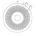
- the annular stator 40 has a core back portion 43. Twenty-four teeth 44 extend radially inward from the core back portion 43. A gap between adjacent teeth 44 forms a slot 45. The teeth 44 and the slot 45 constitute a stator core 41. Further, a rotor 50 having a rotor core 51 and a shaft 14 is provided inside the stator 40 in the radial direction. Twenty permanent magnets 52 are attached to the outer periphery of the rotor core 51 at equal intervals in the circumferential direction of the rotor 50. That is, the rotor 50 has 20 poles.
- a stator winding 42 that is an armature winding is wound around the teeth 44 by concentrated winding.
- a portion of the stator winding 42 that is intensively wound around each tooth 44 is referred to as a “coil portion”.
- the coil portion wound on the inner side in the radial direction of each tooth 44 is a first system coil portion 46
- the coil portion wound on the outer side in the radial direction of each tooth 44 is a second system coil portion 47. is there.
- the number of turns of the first system coil unit 46 and the second system coil unit 47 is the same. 2 and subsequent drawings, the insulator provided between the stator winding 42 and the stator core 41 and the outer periphery of the stator core 41 are provided for the sake of simplicity. The description of the frame is omitted.
- the first system power supply source 20 (see FIG. 1) for applying a current is connected to the first system coil unit 46.
- the first system coil unit 46 is configured as a first system winding group in which three-phase windings of U phase, V phase, and W phase are combined.
- a second system power supply source 30 (see FIG. 1) for applying a current is connected to the second system coil unit 47.
- the second system coil unit 47 is configured as a second system winding group in which three-phase windings of U phase, V phase, and W phase are combined.
- the electric drive device 100 has the first system power supply source 20 and the second system power supply source 30, and as shown in FIG. A first system coil unit 46 and a second system coil unit 47 are provided.
- the electric drive device 100 operates in the same manner as in the normal state by the power supply source of the system that has not failed. It is possible to continue.
- the electric drive device 100 can continue to operate in the same manner as normal by the non-failed system coil unit. It is.
- the first system coil unit 46 and the second system coil unit 47 are disposed in the slot 45 so as to be separated from each other in the radial direction of the stator 40.
- a magnetic interference reducing member 48 is disposed between the first system coil unit 46 and the second system coil unit 47.
- the magnetic interference reducing member 48 is composed of a magnetic body formed separately from the teeth 44 and the core back portion 43.
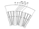
- FIG. 3 shows an enlarged view of a part of the stator 40 shown in FIG.
- adjacent teeth 44a and teeth 44b are shown.
- the magnetic interference reducing member 48 is disposed so as to have a slight gap with respect to the adjacent teeth 44a and teeth 44b.
- the magnetic interference reducing member 48 is disposed so as to have a slight gap with respect to the adjacent teeth with respect to the other teeth of the stator 40.
- the first system coil unit 46U wound around the teeth 44a is a + U phase winding
- the second system coil unit 47U is a + U phase winding.
- the sign indicates the winding direction of the winding
- the positive sign indicates the case of winding in the clockwise direction
- the negative sign indicates the case of winding in the counterclockwise direction. That is, the 1st system coil part and the 2nd system coil part wound by the same tooth are the same winding directions.
- the first system power supply source 20 or the second system power supply source 30 fails, and only the winding group of any system is energized.
- the magnetic symmetry in the rotating electrical machine 10 can be made the same as in the normal state. Further, even when the first system coil unit 46 or the second system coil unit 47 breaks down and energizes only the winding group of either system, the magnetic symmetry in the rotating electrical machine 10 is normal. It can be the same as the time. As a result, no imbalance occurs in the rotation of the rotating electrical machine 10, and an effect of suppressing an increase in torque ripple is obtained.
- FIG. 4 differs from the first embodiment in that magnetic interference is reduced between the first system coil unit 46 and the second system coil unit 47.
- the structure of the stator 400 which does not have the member 48 (refer FIG. 2) is shown.
- Other configurations are the same as those of the stator 40 shown in FIG. 5A is an enlarged view showing the flow of magnetic flux of the stator 400 that does not have the magnetic interference reducing member 48 shown in FIG.
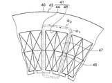
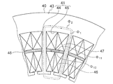
- the in stator 400 having no magnetic interference reducing member 48, the magnetic path the magnetic flux phi 2 of the magnetic flux phi 1 and the second system coil portion 47 of the first system coil portion 46 through which coincide, the Magnetic interference between the first system coil unit 46 and the second system coil unit 47 is large.
- FIG. 5B is an enlarged view showing the flow of magnetic flux of the stator 40 shown in FIG.
- ⁇ 11 that is a part of the magnetic flux of the first system coil unit 46
- ⁇ 12 that is a part of the magnetic flux of the second system coil unit 47. Flows through the magnetic interference reducing member 48.
- A be the inductance corresponding to the magnetic flux flowing through the magnetic interference reducing member 48.
- the current flowing through the first system coil unit 46 is IX
- the current flowing through the second system coil unit 47 is IY.
- M be the alternate inductance between the first system coil unit 46 and the second system coil unit 47.
- L be the self-inductance of the first system coil unit 46.
- IX IY is set in order to simplify the calculation.
- the magnetic interference rate (MA) / (L + A) in the stator 40 shown in FIG. 5B is smaller than the magnetic interference rate M / L in the stator 400 shown in FIG. 5A. That is, by providing the magnetic interference reducing member 48 on the stator 40, the magnetic interference rate between the first system coil unit 46 and the second system coil unit 47 can be reduced.
- FIG. 6 is a graph showing the reduction of the magnetic interference rate by the magnetic interference reducing member 48.
- the vertical axis represents M / L, that is, the magnetic interference rate between the first system coil unit 46 and the second system coil unit 47.
- the horizontal axis is a value normalized by assuming that the value of torque in a rotating electrical machine having a stator 400 that does not have the magnetic interference reducing member 48 is 1.0.
- the magnetic interference rate can be reduced by about 40%. Thereby, the controllability of the rotating electrical machine 10 is improved, and an effect of stabilizing the operation can be obtained.
- the stator 400 that does not have the magnetic interference reducing member 48, when current is applied only to the winding group of either the first or second system due to current supply reduction or coil failure, in the circumferential direction, The magnetic force generated by the application of current locally increases.
- the axial length of the rotating electrical machine 10 needs to be doubled.
- the torque reduction rate of the rotating electrical machine 10 caused by the leakage magnetic flux from the magnetic interference reducing member 48 is about 15%.
- the axial length of the rotating electrical machine 10 may be 1.18 times. Therefore, as compared with the case where the stator 400 without the magnetic interference reduction member 48 is used, an effect that the required length in the axial direction of the rotating electrical machine 10 is shortened and the rotating electrical machine 10 is reduced in size can be obtained. .
- the rotating electrical machine 10 is the rotating electrical machine 10 including the annular stator 40.
- the stator 40 is wound around the core back portion 43, the plurality of teeth 44 extending radially inward from the core back portion, the slots 45 formed between the teeth 44, and wound around the teeth 44.
- the first system coil unit 46 and the second system coil unit 47, and the first system coil unit 46 and the second system coil unit 47 are arranged so as to be separated from each other.
- the magnetic interference reducing member 48 that reduces the magnetic interference between the coil portions 47, the magnetic interference can be reduced and deterioration of controllability due to the magnetic interference can be suppressed.
- the magnetic interference reducing member 48 is provided as a separate body from the teeth 44 and the core back portion 43, the magnetic interference reducing member 48 can be easily manufactured.
- the first system coil unit 46 and the second system coil unit 47 are separated from each other in the radial direction of the stator 40, but are not strictly separated from each other in the radial direction.
- the first system coil unit 46 and the second system coil unit 47 may be separated in an oblique direction with respect to the radial direction.
- the shape of the magnetic interference reducing member 48 may be a shape other than the shape shown in FIG. 3 as long as the first system coil unit 46 and the second system coil unit 47 can be separated from each other. .
- Embodiment 2 a second embodiment of the present invention will be described.
- the same reference numerals as those in FIGS. 1 to 6 are the same or similar components, and detailed description thereof is omitted.
- the number of turns and applied current of the first system coil unit and the second system coil unit are different from those of the first embodiment.
- the first system coil portion 46 b is disposed inside the slot 45 in the radial direction
- the second system coil portion 47 b is disposed outside the slot 45 in the radial direction.
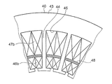
- the number of turns of the first system coil unit 46b is configured to be smaller than the number of turns of the second system coil unit 47b.
- the current value of the first system power supply source 20 (see FIG. 1) applied to the first system coil unit 46b is based on the current value of the second system power supply source 30 applied to the second system coil unit 47b. Is also configured to be small. Other configurations are the same as those of the first embodiment.
- the number of turns of the coil unit and the applied current value are Different. Therefore, when the stator 40 of the rotating electrical machine 10 of the electric drive device 100 (see FIG. 1) is used for, for example, an electric power steering of an automobile, the first system has a small coil winding and a small applied current.
- the first system coil unit 46b and the first system power supply source 20 may be used. Thereby, the inverter used for the 1st system drive circuit 23 of the 1st system power supply source 20 can be made into a low capacity type inverter with small current capacity, calorific value, and failure rate.
- the electric driving device 100 can reduce the reliability required for the automatic driving device at low cost. There is an advantage that it becomes easy to satisfy.
- the electric drive device 100 can output the required strength while suppressing power consumption.
- the current value applied by the first system power supply source 20 to the first system coil unit 46b is smaller than the current value applied by the second system power supply source 30 to the second system coil unit 47b. is there. Further, the number of turns of the first system coil unit 46b is smaller than the number of turns of the second system coil unit 47b. Therefore, it is possible to improve the reliability of the electric drive device and suppress the power consumption by using the inverter used in the first system drive circuit 23 as a low-capacity inverter.
- the current value applied to the first system coil unit 46b is smaller than the current value applied to the second system coil unit 47b, and the number of turns of the first system coil unit 46b is Although it is smaller than the number of turns of the second system coil portion 47b, it is not limited to this configuration.
- the current value applied to the first system coil unit 46b is larger than the current value applied to the second system coil unit 47b, and the number of turns of the first system coil unit 46b is the number of turns of the second system coil unit 47b. May be larger.
- the number of turns of the first system coil unit 46b is the same as the number of turns of the second system coil unit 47b, and the current value applied to the first system coil unit 46b and the current applied to the second system coil unit 47b.
- the configuration may be different from the value.
- the current value applied to the first system coil unit 46b and the current value applied to the second system coil unit 47b are the same, and the number of turns of the first system coil unit 46b and the second system coil unit 47b A configuration in which the number of turns is different may be used.
- Embodiment 3 a third embodiment of the present invention will be described.
- the shape of the magnetic interference reducing member is changed with respect to the first embodiment.
- two magnetic interference reducing members 48 a arranged in the slot 45 are arranged side by side with a gap 49 in the circumferential direction of the slot 45. That is, with respect to the magnetic interference reducing member 48 of the first embodiment, two magnetic interference reducing members 48a whose circumferential length is about half of the slot 45 are arranged side by side.
- Other configurations are the same as those of the first embodiment.
- Two magnetic interference reducing members 48a whose circumferential length is about half that of the slot 45 are arranged side by side in the circumferential direction, so that the magnetic interference reducing member 48a can be used in the first system coil portion when the rotary electric machine 10 is assembled. It becomes easy to arrange
- Embodiment 4 FIG. Next, a fourth embodiment of the present invention will be described.
- the shape of the magnetic interference reducing member is extended in the radial direction with respect to the first embodiment.
- the two second system coil portions 47 are arranged apart from each other in the circumferential direction.
- the magnetic interference reduction member 48b is disposed in the circumferential direction between the first system coil unit 46 and the second system coil unit 47, and at a portion where the two second system coil units 47 are separated from each other. It is arranged to extend radially outward. That is, the magnetic interference reducing member 48b has an L shape.
- the magnetic interference reducing member 48c is disposed in the circumferential direction between the first system coil unit 46 and the second system coil unit 47, and the two second system coil units 47 are spaced apart from each other.
- the outer side extends radially outward. That is, the magnetic interference reducing member 48c has an L shape.
- the magnetic interference reducing member 48 b and the magnetic interference reducing member 48 c are arranged so as to have a slight gap with respect to the core back portion 43. Further, the magnetic interference reducing member 48b and the magnetic interference reducing member 48c are arranged side by side in the circumferential direction. Furthermore, a gap is provided between the magnetic interference reducing member 48b and the magnetic interference reducing member 48c.
- the magnetic interference reducing member 48b and the magnetic interference reducing member 48c have the first system coil unit 46 and the second system coil unit 47 having a diameter. In addition to being separated in the direction, the adjacent second system coil portions 47 are separated from each other in the circumferential direction. With this configuration, the magnetic flux of the second system coil unit 47 passes through the magnetic interference reduction member 48b and the magnetic interference reduction member 48c and is linked to the core back unit 43. Therefore, the first system coil unit 46 and the second system coil unit 47 Can be further reduced.
- the magnetic interference reduction member 48b and the magnetic interference reduction member 48c separate the adjacent second system coil portions 47 in the circumferential direction, the magnetic force between the first system coil portion 46 and the second system coil portion 47 is reduced.
- the interference rate can be further reduced.
- the magnetic interference reducing members 48b and 48c are arranged extending in the radial direction between the two second system coil portions 47, but may have other shapes.
- the two first system coil portions 46 may extend inward in the radial direction between the two first system coil portions 46 and may be separated from each other in the circumferential direction.
- the first system coil unit 46 or the second system coil unit 47 is separated in the circumferential direction of the stator 40, but is not necessarily strictly separated in the circumferential direction.
- the first system coil unit 46 or the second system coil unit 47 may be separated in an oblique direction with respect to the circumferential direction.
- Embodiment 5 a fifth embodiment of the present invention will be described.
- the shape of the magnetic interference reducing member is extended in the radial direction with respect to the first embodiment.
- the two adjacent first system coil portions 46 are spaced apart in the circumferential direction.
- Two adjacent second system coil portions 47 are spaced apart in the circumferential direction.
- the magnetic interference reducing member 48d and the magnetic interference reducing member 48e are arranged in the circumferential direction between the first system coil unit 46 and the second system coil unit 47, and two adjacent first system coil units 46 are adjacent to each other. And in the part which two adjacent 2nd system
- the magnetic interference reducing member 48d and the magnetic interference reducing member 48e are arranged so as to have a slight gap with respect to the core back portion 43. Furthermore, the magnetic interference reducing member 48d and the magnetic interference reducing member 48d are arranged side by side in the circumferential direction. Furthermore, a gap is provided between the magnetic interference reducing member 48b and the magnetic interference reducing member 48c.
- the magnetic interference reducing member 48d and the magnetic interference reducing member 48e have the first system coil unit 46 and the second system coil unit 47 having a diameter.
- the first system coil unit 46 and the adjacent second system coil unit 47 adjacent to each other are separated from each other in the circumferential direction and separated from each other in the circumferential direction.
- the magnetic interference reduction member 48d and the magnetic interference reduction member 48e separate the adjacent first system coil parts and the adjacent second system coil parts 47 in the circumferential direction, the first system coil part The magnetic interference rate between 46 and the second system coil unit 47 can be further reduced.
- the first system coil unit and the second system coil unit are arranged in the circumferential direction with respect to the first embodiment.
- the first system coil portion 46 a is disposed in the slot 45 on the side close to the teeth 44.
- a second system coil portion 47 a is disposed on the side far from the teeth 44.
- the first system coil unit 46 a and the second system coil are arranged in the circumferential direction of the stator 40.
- the first system coil part 46a and the second system coil part 47a are separated from each other, and a magnetic interference reducing member 48f extending in a plate shape in the radial direction of the stator 40 is disposed at the separated part.
- the magnetic interference reducing member 48 f is disposed with a slight gap with respect to the inner wall of the core back portion 43 of the slot 45.
- first system coil unit 46a and the second system coil unit 47a are separated from each other by the magnetic interference reducing member 48f.
- Two combinations of the first system coil unit 46a, the magnetic interference reducing member 48f, and the second system coil unit 47a are arranged in the slot 45.
- Other configurations are the same as those of the first embodiment.
- the first system coil unit 46a and the second system coil unit 47a are arranged side by side in the circumferential direction, and the magnetic interference reduction member 48f is disposed therebetween, so that the first system coil unit 46a and the second system coil unit 47a are arranged.
- the magnetic interference reducing member 48f By reducing the mutual magnetic interference rate and using the magnetic interference reducing member 48f as a reinforcing material, it is possible to obtain an effect that the radial rigidity of the stator 40 can be improved.
- the second system coil unit 47a is arranged on the side far from the teeth 44, but the first system coil unit 46a may be arranged on the side far from the teeth 44.
- the shape of the magnetic interference reducing member 48f is not limited to the shape extending in a plate shape in the radial direction shown in FIG. As long as the first system coil unit 46a and the second system coil unit 47a are separated and separated, the shape of the magnetic interference reducing member 48f may be other shapes.
- the combination of the first system coil unit 46a, the magnetic interference reducing member 48f, and the second system coil unit 47a is arranged in the slot 45 in pairs, but other than this It may be a combination.
- the combinations of the first system coil unit 46a, the magnetic interference reducing member 48f, and the second system coil unit 47a are arranged in pairs, this adjacent combination.
- a magnetic interference reducing member 48f may be further disposed between them.
- Embodiment 7 FIG. Next, a seventh embodiment of the present invention will be described.
- the magnetic interference reduction unit is brought into contact with the adjacent teeth with respect to the first embodiment.
- a contact portion 48 h which is an end portion in the circumferential direction of the magnetic interference reducing member 48 g disposed in the slot 45 is in contact with the adjacent teeth 44 in the circumferential direction of the stator 40.
- Other configurations are the same as those of the first embodiment.
- the magnetic interference reducing member 48g contacts the teeth 44 in the circumferential direction of the stator 40, the magnetic resistance of the teeth 44 and the magnetic interference reducing member 48g is lowered. For this reason, the effect that the magnetic interference reduction effect by the magnetic interference reduction member 48g becomes large is acquired. Further, since the magnetic interference reducing member 48g contacts the teeth 44, an effect that the rigidity of the stator 40 can be increased is obtained.
- Embodiment 8 an eighth embodiment of the present invention will be described.
- the magnetic interference reducing portion is brought into contact with the teeth and the core back portion in the radial direction with respect to the sixth embodiment.
- a plate-like magnetic interference reducing member 48j extending in the radial direction is disposed between the first system coil unit 46a and the second system coil unit 47a.
- an abutting portion 48k that is an end portion of the magnetic interference reducing member 48j abuts on the core back portion 43.
- the contact portion 48k of the magnetic interference reducing member 48j is in contact with the tip portion 44f of the tooth 44 having a bowl shape.
- Other aspects are the same as in the sixth embodiment.
- the radial contact portion 48k of the magnetic interference reducing member 48g is in contact with at least one of the tip end portion 44f and the core back portion 43 of the tooth 44, the tooth 44 and the magnetic interference reducing member The magnetic resistance of 48j is lowered. For this reason, the effect that the magnetic interference reduction effect by the magnetic interference reduction member 48j becomes large is acquired. Moreover, the effect which can make the rigidity of the stator 40 high can be acquired.
- Embodiment 9 a ninth embodiment of the present invention will be described.
- the stator 40c includes a plurality of core back portions 43c and teeth 44c formed integrally with the core back portion 43c.
- a first system coil unit 46 and a second system coil unit 47 are wound around the teeth 44c.
- the first system coil unit 46 is disposed on the inner side in the radial direction, and the second system coil unit 47 on the outer side in the radial direction. Is arranged.
- a magnetic interference reducing member 48m is arranged between the first system coil unit 46 and the second system coil unit 47.
- the magnetic interference reducing member 48m is formed integrally with the teeth 44c.
- a gap 49a is formed in the circumferential direction between the magnetic interference reducing members 48m.
- FIG. 16 shows a configuration of the core sheet 40c1 before the core back portion 43c and the teeth 44c are assembled by stacking the stator 40c shown in FIG.
- the first system coil unit 46 and the second system coil unit 47 are not yet arranged.
- the core sheet 40c1 has a structure that is divided in the circumferential direction at a central portion between a plurality of adjacent core sheets 40c1. That is, the core sheet 40c1 has a circumferentially divided structure.
- Each tooth 44c1 is formed integrally with each core back portion 43c1 divided in the circumferential direction.
- the core sheet teeth 44c1 forming the stator 40c are formed with magnetic interference reducing members 48m1 that project symmetrically in the circumferential direction of the core sheet 40c1.
- the annular stator 40c shown in FIG. 15 can be formed by joining and laminating the core back portion 43c1 with the adjacent core back portion 43c1. After forming the stator 40c, the first system coil unit 46 and the second system coil unit 47 are wound around the teeth 44c. Other configurations are the same as those of the first embodiment.
- the stator 40c is divided in the circumferential direction for each tooth 44c, the first system coil unit 46 and the second system coil unit 47 are wound around the tooth 44c, and the stator 40c is formed in an annular shape. .
- the teeth 44c and the magnetic interference reducing member 48m are integrally formed. Therefore, as compared with the case where the first system coil unit 46 and the second system coil unit 47 are wound around the teeth 44 of the formed stator 40 as in the first embodiment, the first system coil is connected to the teeth 44c.
- strain coil part 47 is acquired. Further, the stator 40c can be easily manufactured by the circumferential division structure.
- Embodiment 10 FIG. Next, an embodiment 10 of the invention will be described.
- adjacent teeth are coupled to the first embodiment inside in the radial direction.
- the stator 40d is formed with an annular core back portion 43d and a plurality of teeth 44d extending radially inward from the inner periphery of the core back portion 43d.
- the core back portion 43d is formed separately from the teeth 44d and constitutes the outer iron core 43e.
- the radially inner flange portion of each tooth 44d is integrally formed with an adjacent end portion, and the teeth 44d constitute an inner iron core 44e as a whole.
- the outer iron core 43e and the inner iron core 44e are joined by an arcuate fitting portion 44g.
- Other configurations are the same as those of the first embodiment.
- each tooth 44d is integrally formed by joining the adjacent end portions, magnetic interference between the first system coil unit 46 and the second system coil unit 47 is increased.
- the magnetic interference reducing member 48 is disposed between the first system coil unit 46 and the second system coil unit 47, the first system coil unit 46, the second system coil unit 47, and the magnetic interference rate are arranged. Is reduced.
- stator 40d has an inner and outer iron core structure of an outer iron core 43e and an inner iron core 44e, and the inner iron core 44e around which the first system coil portion 46 and the second system coil portion 47 are wound is combined with the outer iron core 43e.
- the stator 40d can be easily configured, and the productivity of the stator 40d is improved.
- the stator 40d is divided into an inner iron core 44e composed of a plurality of teeth 44d and an outer iron core 43e composed of a core back portion 43d, and the first system coil unit 46 and the second system coil unit 47 are wound.
- the rotated inner core 44e is combined with the outer core 43e to form the stator 40d.
- productivity of the stator 40d can be improved, reducing a magnetic interference rate.
- the shape of the fitting portion 44g between the outer iron core 43e and the inner iron core 44e is an arc shape, but is not limited to this shape.
- the shape of the fitting portion 44g may be a polygon such as a regular octagon.
- the magnetic interference reducing member is formed in a cross shape with respect to the first embodiment.
- the adjacent first system coil unit 46 and second system coil unit 47 are arranged to be separated from each other in the radial direction. Further, the adjacent first system coil portions 46 are spaced apart from each other in the circumferential direction. Further, the adjacent second system coil portions 47 are arranged apart from each other in the circumferential direction.
- the magnetic interference reducing member 48p is disposed at a location where the first system coil units 46 and the second system coil units 47 are separated from each other.
- the magnetic interference reducing member 48p is formed in a cross shape. Other configurations are the same as those of the first embodiment.
- the rigidity of the stator 40 can be ensured while reducing the magnetic interference rate of each first system coil unit 46 and each second system coil unit 47.
- Embodiment 12 FIG. Next, an embodiment 12 of the invention will be described.
- a magnetic interference reducing member is inserted only in the same phase in the first system coil section and each second system coil section with respect to the first embodiment.
- the stator 40 has 24 teeth 44.
- the rotor 50 has 20 poles.
- the coils arranged in the first system coil unit 46 are U11 +, U12 ⁇ , W11 ⁇ , W12 +, V11 +, V12 ⁇ , U13 ⁇ , U14 +, W13 +, W14 ⁇ , V13 ⁇ , V14 +, U15 +, U16 in the clockwise direction.
- -, W15-, W16 +, V15 +, V16-, U17-, U18 +, W17 +, W18-, V17-, V18 + are arranged in this order and are connected to the first system power supply source 20.
- the coils arranged in the second system coil unit 47 are U21 +, U22 ⁇ , W21 ⁇ , W22 +, V21 +, V22 ⁇ , U23 ⁇ , U24 +, W23 +, W24 ⁇ , V23 ⁇ , V24 +, U25 + in the clockwise direction.
- U26 ⁇ , W25 ⁇ , W26 +, V25 +, V26 ⁇ , U27 ⁇ , U28 +, W27 +, W28 ⁇ , V27 ⁇ , and V28 + are arranged in this order.
- a magnetic interference reducing member 48 is disposed between the first system coil unit 46 and the second system coil unit 47 in the slot 45 where the in-phase winding is disposed.
- U11 + and U21 +, W11 ⁇ and W21 ⁇ , V11 + and V21 +, U13 ⁇ and U23 ⁇ , W13 + and W23 +, V13 ⁇ and V23 ⁇ , U15 + and U25 +, W15 ⁇ and W25 ⁇ , V15 + and V25 +, U17 Magnetic interference reducing members 48 are arranged between-and U27-, W17 + and W27-, V18 + and V28-, respectively. That is, in each slot 45, the magnetic interference reducing member 48 is arranged between the first system coil unit 46 and the second system coil unit 47 every other one.
- Embodiment 13 FIG. Next, a thirteenth embodiment of the present invention will be described.
- the first system coil portions are alternately arranged on the radially inner side and the radially outer side of the slot.
- the second system coil portions are alternately arranged on the radially outer side and the radially inner side of the slot.
- the stator 40 has 24 teeth 44.
- the rotor 50 has 20 poles.
- the coils arranged in the first system coil section 46 are U11 +, U22 ⁇ , W11 ⁇ , W22 +, V11 +, V22 ⁇ , U13 ⁇ , U24 +, W13 +, W24 ⁇ , V13 ⁇ , V24 +, U15 +, U26 in the clockwise direction.
- -, W15-, W26 +, V15 +, V26-, U17-, U28 +, W17 +, W28-, V17-, V28 + are arranged in this order.
- the coils arranged in the second system coil unit 47 are U21 +, U12 ⁇ , W21 ⁇ , W12 +, V21 +, V12 ⁇ , U23 ⁇ , U14 +, W23 +, W14 ⁇ , V23 ⁇ , V14 +, U25 + in the clockwise direction.
- U16 ⁇ , W25 ⁇ , W16 +, V25 +, V16 ⁇ , U27 ⁇ , U18 +, W27 +, W18 ⁇ , V27 ⁇ , and V18 + are arranged in this order.
- U11 +, U12 ⁇ , W11 ⁇ , W12 +, V11 +, V12 ⁇ , U13 ⁇ , U14 +, W13 +, W14 ⁇ , V13 ⁇ , V14 +, U15 +, U16 ⁇ , W15 ⁇ , W16 +, V15 +, V16 ⁇ , U17 ⁇ , U18 +, W17 +, W18 ⁇ , V17 ⁇ , V18 + are coils of the first winding system group, and are connected to the first system power supply source 20.
- the coils U28 +, W27 +, W28 ⁇ , V27 ⁇ , V28 + are coils of the second winding system group, and are connected to the second system power supply source 30.
- the coil of the first winding system group is arranged in the first system coil unit 46, and the coil of the second winding system group is arranged in the second system coil unit 47.
- the coil of the second winding system group is arranged in the first system coil unit 46, and the coil of the first winding system group is arranged in the second system coil unit 47.
- a slot 45 is disposed. Therefore, the positional relationship in the radial direction of the coils of the first winding system group and the second winding system group differs between adjacent slots 45. Moreover, the positional relationship of the coil of the circumferential direction of the 1st winding system group and the 2nd winding system group may differ between 45 of adjacent slots.
- the stator 40 has 24 teeth 44, and the rotor 50 has 20 poles.
- the number of stator teeth other than this and the rotor It may be the number of poles.
- Embodiment 14 FIG. Next, a fourteenth embodiment of the present invention will be described.
- the rotating electrical machine 10 of the first to thirteenth embodiments is used in an electric power steering apparatus for an automobile.
- An electric power steering apparatus 200 for an automobile shown in FIG. 21 will be described.
- the driver steers a steering wheel (not shown), and the steering torque is transmitted to the input sensor 201 via a steering device (not shown).
- the torque sensor 202 detects this torque and inputs it to the first system power supply source 20 and the second system power supply source 30.
- the first system power supply source 20 and the second system power supply source 30 are supplied with power from a battery (not shown) via the power connectors 28 and 38 (first system connector and second system connector).
- vehicle information such as vehicle speed is input to the first system power supply source 20 and the second system power supply source 30.
- the first system power supply source 20 and the second system power supply source 30 calculate necessary assist torque from the steering torque and vehicle information such as vehicle speed, and supply power to the permanent magnet type rotating electrical machine 10. .
- the rotating electrical machine 10 is arranged in a direction parallel to a moving direction A of a rack shaft (not shown).
- the torque generated by the rotating electrical machine 10 is transmitted to a gear box 203 in which a belt and a ball screw (not shown) are incorporated.
- the torque generated by the rotating electrical machine 10 is decelerated by the gear box 203 to move the rack shaft 204 provided in the housing in the movement direction A.
- the tie rod 206 moves and assists the driver's steering force to steer the vehicle tire. Therefore, the driver can turn the vehicle with a small force.
- the cogging torque and torque ripple generated by the rotating electrical machine 10 are transmitted to the driver via a gear of the steering apparatus (not shown). Therefore, in order to obtain a good steering feeling, it is desirable that the cogging torque and the torque ripple are small. Further, it is desirable that the vibration and noise of the rotating electrical machine 10 are also small.
- the rotating electrical machine 10 for the electric power steering device 200 of an automobile, in particular, the winding group of the electric power steering device 200 or the first system power supply source 20a, the second Even when the grid power supply source 30a fails, the driver's steering force can be stably assisted.
- the normal time there is an advantage that a stable controllability and a comfortable steering pipe can be obtained.
- the electric power steering apparatus 200 having the rotating electrical machine 10 can stably assist the driver's steering force in the event of a failure.
- the stators 40, 40a, 40b, 40c, 40d have 24 teeth 44, and the rotor 50 has 20 poles. It may be the number of teeth of the stator and the number of poles of the rotor. In the first to thirteenth embodiments, the stators 40, 40a, 40b, 40c, and 40d have the first system coil unit and the second system coil unit. You may do it.
- Rotating electric machine 40, 40a, 40b, 40c, 40d Stator, 43, 43c, 43d Core back part, 43e Outer iron core, 44, 44a, 44b, 44c, 44d Teeth, 44e Inner iron core, 44f Tip, 45 slots 46, 46a, 46b, 46U First system coil section, 47, 47a, 47b, 47U Second system coil section, 48, 48a, 48b, 48c, 48d, 48e, 48f, 48g, 48j, 48m, 48p Magnetic interference Reduction member.
Landscapes
- Engineering & Computer Science (AREA)
- Power Engineering (AREA)
- Windings For Motors And Generators (AREA)
- Iron Core Of Rotating Electric Machines (AREA)
Abstract
固定子40は、コアバック部43と、コアバック部から径方向の内側に延びる複数のティース44と、ティース44毎に巻回された第1系統コイル部46及び第2系統コイル部47と、第1系統コイル部46及び第2系統コイル部47の間に配置され、第1系統コイル部46及び第2系統コイル部47の間の磁気干渉を低減する磁気干渉低減部材48とを有する。また、第1系統コイル部46及び第2系統コイル部47は、第1系統コイル部46及び第2系統コイル部47毎に異なる、第1系統電力供給源20又は第2系統電力供給源30に接続されている。
Description
この発明は、複数の巻線群を有する回転電機及び回転電機を有する電動パワーステアリング装置に関する。
特許文献1に記載されている回転電機のように、1つのティースに複数の巻線群を巻回し、電流を流す巻線群を切替える回転電機が知られている。
しかしながら、特許文献1に記載されている回転電機において、1つのティースに複数の巻線群を巻回すると、各巻線群間の磁気干渉の影響が大きくなる。この結果、回転電機の制御性が悪化するという問題があった。
この発明は、このような課題を解決するためになされたものであり、1つのティースに複数の巻線群が巻回される場合に、磁気干渉による制御性の悪化を抑制することのできる回転電機及び回転電機を有する電動パワーステアリング装置を提供することを目的とする。
上記の課題を解決するために、この発明に係る回転電機は、円環状の固定子を備える回転電機であって、固定子は、コアバック部と、コアバック部から径方向の内側に延びる複数のティースと、ティース毎に巻回された複数の巻線群と、隣り合う巻線群の間に配置され、巻線群の間の磁気干渉を低減する磁気干渉低減部材とを有し、巻線群は、巻線群毎に異なる電力供給源に接続され、巻線群は、磁気干渉低減部材により、他の巻線群と固定子の径方向又は周方向に離間する。
この発明に係る回転電機は、上記の構成により、1つのティースに複数の巻線群が巻回されている場合に、磁気干渉による制御性の悪化を抑制することのできる回転電機及び回転電機を有する電動パワーステアリング装置を得ることができる。
実施の形態1.
以下、この発明の実施の形態1について添付図面に基づいて説明する。
図1に示すように、電動駆動装置100は、回転電機10と、第1系統電力供給源20と、第2系統電力供給源30とを備えている。第1系統電力供給源20及び第2系統電力供給源30は、回転電機10の巻線に三相交流電流を印加するそれぞれ独立したインバータ装置を構成している。すなわち、この回転電機10は、2系統の三相交流電力により駆動する回転電機である。
以下、この発明の実施の形態1について添付図面に基づいて説明する。
図1に示すように、電動駆動装置100は、回転電機10と、第1系統電力供給源20と、第2系統電力供給源30とを備えている。第1系統電力供給源20及び第2系統電力供給源30は、回転電機10の巻線に三相交流電流を印加するそれぞれ独立したインバータ装置を構成している。すなわち、この回転電機10は、2系統の三相交流電力により駆動する回転電機である。
回転電機10は、永久磁石型集中巻回転電機であり、各部品を収容するフレーム11を有している。フレーム11は、回転電機10の前面ハウジング12に図示しないボルトで接合されている。フレーム11の内壁には、固定子40が配置されている。固定子40は、固定子鉄心41と、固定子鉄心41に巻回されている固定子巻線42とを有する。固定子鉄心41は、磁性体で形成されたコアシートを積層して構成されている。この磁性体は、例えば電磁鋼板であってもよい。また、固定子鉄心41は電機子鉄心であり、固定子巻線42は電機子巻線である。
固定子40に対して径方向内側に、回転可能に形成された回転子50が設けられている。回転子50は、回転子鉄心51と、回転子鉄心51に取り付けられた永久磁石52とを有している。回転子鉄心51の中心にはシャフト14が取り付けられている。シャフト14は、ベアリング13a及びベアリング13bにより回転可能に支持されている。シャフト14と回転子50とは、固定子40に対して回転可能に設けられている。
回転子50の回転数を検出するために、シャフト14の端部に取り付けられたホルダ15と、ホルダ15に保持されて回転子50と同じ速度で回転するセンサマグネット16とが設けられている。また、センサマグネット16に対向する第1基板21が設けられている。第1基板21上には、半導体センサ22が実装されている。半導体センサ22は、センサマグネット16の回転数を検出して、回転子50の回転数を検出する。
また、電動駆動装置100には、第1系統駆動回路23及び第2系統駆動回路33が設けられている。第1系統駆動回路23は、固定子巻線42のうち第1系統の巻線に電流を印加するための駆動回路である。また、第2系統駆動回路33は、固定子巻線42のうち第2系統の巻線に電流を印加するための駆動回路である。第1系統駆動回路23及び第2系統駆動回路33は、配線27により第2基板24に接続されている。また、半導体センサ22は配線26により第2基板24に接続されている。
第2基板24には、第1系統制御回路25と、第2系統制御回路35が設けられている。第1系統制御回路25は、第1系統駆動回路23を制御するための制御回路である。また、第2系統制御回路35は、第2系統駆動回路33を制御するための制御回路である。
第1系統制御回路25及び第2系統制御回路35は、半導体センサ22が検出した回転子50の回転数の情報に基づいて、第1系統駆動回路23及び第2系統駆動回路33を制御する。第1系統制御回路25は第1系統コネクタ28に接続されており、第2系統制御回路35は第2系統コネクタ38に接続されている。第1系統コネクタ28及び第2系統コネクタ38は、図示しない外部電源によりそれぞれの電力供給源に電力を供給するために設けられている。第1系統駆動回路23、第1系統制御回路25及び第1系統コネクタ28は第1系統電力供給源20を構成し、第2系統駆動回路33、第2系統制御回路35及び第2系統コネクタ38は第2系統電力供給源30を構成している。
図2に示すように、円環状の固定子40は、コアバック部43を有している。コアバック部43から径方向の内側に、24個のティース44が延びている。また、隣り合うティース44同士の間隙が、スロット45を構成している。ティース44及びスロット45は、固定子鉄心41を構成している。また、固定子40の径方向の内側に、回転子鉄心51及びシャフト14を有する回転子50が設けられている。回転子鉄心51の外周には、回転子50の周方向に等間隔に20個の永久磁石52が取り付けられている。すなわち、回転子50の極数は20個である。
ティース44には、集中巻によって電機子巻線である固定子巻線42が巻回されている。固定子巻線42のうち各ティース44に集中的に巻回されている部分を「コイル部」と呼ぶ。各ティース44の径方向の内側に巻回されているコイル部は第1系統コイル部46であり、各ティース44の径方向の外側に巻回されているコイル部は第2系統コイル部47である。第1系統コイル部46及び第2系統コイル部47の巻数は、同じ巻数である。なお、説明を簡単にするために、図2及びそれ以降の図面においては、固定子巻線42と固定子鉄心41との間に設けられるインシュレータの記載と、固定子鉄心41の外周に設けられるフレームの記載とを省略する。
第1系統コイル部46には、電流を印加するための第1系統電力供給源20(図1参照)が接続されている。第1系統コイル部46は、U相、V相、W相の三相の巻線を一組とした、第1系統巻線群として構成されている。同様に、第2系統コイル部47には、電流を印加するための第2系統電力供給源30(図1参照)が接続されている。第2系統コイル部47は、U相、V相、W相の三相の巻線を一組とした、第2系統巻線群として構成されている。
上記に説明した通り、図1に示すように、電動駆動装置100が第1系統電力供給源20及び第2系統電力供給源30を有し、図2に示すように、固定子巻線42が第1系統コイル部46及び第2系統コイル部47を有する。これにより、第1系統電力供給源20又は第2系統電力供給源30が故障した場合であっても、故障していない系統の電力供給源により、電動駆動装置100が正常時と同様に動作し続けることが可能である。また、第1系統コイル部46又は第2系統コイル部47が故障した場合であっても、故障していない系統のコイル部により、電動駆動装置100が正常時と同様に動作し続けることが可能である。
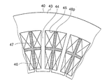
第1系統コイル部46と第2系統コイル部47とは、固定子40の径方向に離間して、スロット45内に配置されている。第1系統コイル部46と第2系統コイル部47との間には、磁気干渉低減部材48が配置されている。磁気干渉低減部材48は、ティース44及びコアバック部43と別体に形成された磁性体により構成されている。
図3に、図2に示す固定子40の一部分の拡大図を示す。図3においては、隣り合うティース44a及びティース44bを示している。固定子40の周方向において、磁気干渉低減部材48は、隣り合うティース44a及びティース44bに対して、わずかに隙間を有するように配置されている。また、固定子40が有する他のティースに対しても、磁気干渉低減部材48は隣り合うティースに対して、わずかに隙間を有するように配置されている。
ティース44aに巻回された第1系統コイル部46Uは+U相の巻線であり、第2系統コイル部47Uは+U相の巻線である。ここで、符号は巻線の巻回方向を示しており、正の符号は時計回りに巻回した場合を示し、負の符号は反時計回りに巻回した場合を示す。すなわち、同じティースに巻回される第1系統コイル部及び第2系統コイル部は同じ巻回方向である。
このような構成にすることで、第1系統電力供給源20又は第2系統電力供給源30(図1参照)が故障して、いずれかの系統の巻線群にのみ通電する場合であっても、回転電機10における磁気的な対称性を、正常時と同様にすることができる。また、第1系統コイル部46又は第2系統コイル部47が故障して、いずれかの系統の巻線群にのみ通電する場合であっても、回転電機10における磁気的な対称性を、正常時と同様にすることができる。そのため、回転電機10の回転においてアンバランスが生じないため、トルクリップルの増大を抑制できる効果が得られる。
また、いずれかの系統の巻線群にのみ通電する場合に、正常時と同等のトルクを出力するために、正常な系統の巻線群に正常時の2倍の電流を印加する場合がある。この場合であっても、回転子50(図2参照)の永久磁石52にかかる逆磁界が増大しない。このため、永久磁石52が減磁されて回転電機10のトルクが減少することを防ぐ効果が得られる。
この実施の形態1の固定子40との比較説明のために、図4にこの実施の形態1とは異なり、第1系統コイル部46と第2系統コイル部47との間に、磁気干渉低減部材48(図2参照)を有さない固定子400の構成を示す。その他の構成は図2に示す固定子40の構成と同じである。また、図5Aは、図4に示す磁気干渉低減部材48を有さない固定子400の、磁束の流れを示す拡大図である。
図5Aに示す、磁気干渉低減部材48を有さない固定子400では、第1系統コイル部46の磁束φ1及び第2系統コイル部47の磁束φ2が通る磁路が一致するので、第1系統コイル部46と第2系統コイル部47との磁気干渉が大きい。
図5Bは、図2に示す固定子40の磁束の流れを示す拡大図である。磁気干渉低減部材48を有するこの実施の形態1の固定子40では、第1系統コイル部46の磁束の一部であるφ11と、第2系統コイル部47の磁束の一部であるφ12とが、磁気干渉低減部材48を流れる。
磁気干渉低減部材48を流れる磁束に対応するインダクタンスをAとする。また、第1系統コイル部46に流れる電流をIX、第2系統コイル部47に流れる電流をIYとする。さらに、第1系統コイル部46と第2系統コイル部47との交互インダクタンスをMとする。さらにまた、第1系統コイル部46の自己インダクタンスをLとする。電流IXによって第1系統コイル部46に鎖交する磁束φ1は、φ1=L×IX+φ11=L×IX+A×IX=(L+A)×IXと表される。また、電流IYによって第2系統コイル部47に鎖交する磁束φ2は、φ2=M×IY-φ12=M×IY-A×IY=(M-A)×IYと表される。
図5Aに示す固定子400における磁気干渉率は、φ2/φ1=M/Lであるのに対し、図5Bに示すこの実施の形態1の固定子40における磁気干渉率は、φ2/φ1=(M-A)/(L+A)である。ただし、ここでは計算を簡単にするためにIX=IYとしている。図5Aに示す固定子400における磁気干渉率M/Lよりも、図5Bに示す固定子40における磁気干渉率(M-A)/(L+A)が小さくなる。すなわち、磁気干渉低減部材48を固定子40に設けることで、第1系統コイル部46と第2系統コイル部47との磁気干渉率を低減することができる。
図6は、磁気干渉低減部材48による磁気干渉率の低減を示すグラフである。縦軸はM/L、すなわち第1系統コイル部46と第2系統コイル部47との間の磁気干渉率を示す。横軸は、磁気干渉低減部材48を有さない固定子400を有する回転電機におけるトルクの値を1.0として規格化した値である。固定子400を用いる場合に対して、磁気干渉低減部材48を有するこの実施の形態1の固定子40を用いる場合は、磁気干渉率を約40%低減することができる。これにより、回転電機10の制御性が向上し、動作が安定する効果を得ることができる。
また、磁気干渉低減部材48を有さない固定子400では、電流供給減又はコイルの故障により第1、第2のいずれかの系統の巻線群にのみ電流を印加する場合に、周方向において局所的に電流の印加により発生する磁力が強くなる。これにより永久磁石52が減磁されることを避けるために、回転電機10の軸方向の長さを2倍にする必要がある。一方、この実施の形態1の固定子40では、磁気干渉低減部材48からの漏れ磁束に起因する、回転電機10のトルクの低下率は約15%である。このトルクの低下率を補うためには、回転電機10の軸方向の長さを1.18倍とすればよい。したがって、磁気干渉低減部材48を有さない固定子400を用いる場合に対して、回転電機10の軸方向の必要な長さが短くなり、回転電機10が小型になるという効果を得ることができる。
このように、この実施の形態1に係る回転電機10は、円環状の固定子40を備える回転電機10である。固定子40は、コアバック部43と、コアバック部から径方向の内側に延びる複数のティース44と、ティース44の間に形成されたスロット45と、ティース44毎に巻回され、スロット45毎に設置された第1系統コイル部46及び第2系統コイル部47と、第1系統コイル部46及び第2系統コイル部47の離間させるように配置され、第1系統コイル部46及び第2系統コイル部47の間の磁気干渉を低減する磁気干渉低減部材48とを有することで、磁気干渉を低減し、磁気干渉による制御性の悪化を抑制することができる。
また、磁気干渉低減部材48は、ティース44及びコアバック部43とは別体として設けられているので、磁気干渉低減部材48を簡単に製造することができる。
なお、この実施の形態1では第1系統コイル部46と第2系統コイル部47とは、固定子40の径方向に離間していたが、厳密に径方向に離間している必要はない。例えば、は第1系統コイル部46と第2系統コイル部47とは、径方向に対して斜め方向に離間していてもよい。また、磁気干渉低減部材48の形状は、第1系統コイル部46と第2系統コイル部47とを離間させることのできる形状であれば、図3に示した形状以外の形状であってもよい。
実施の形態2.
次に、この発明の実施の形態2について説明する。尚、以下の実施の形態において、図1~図6の参照符号と同一の符号は、同一又は同様な構成要素であるので、その詳細な説明は省略する。
この実施の形態2は、実施の形態1に対して第1系統コイル部及び第2系統コイル部の巻数と印加電流とを異なる値にしたものである。
図7に示すように、スロット45の径方向の内側に第1系統コイル部46bが配置され、スロット45の径方向の外側に第2系統コイル部47bが配置されている。第1系統コイル部46bの巻数は、第2系統コイル部47bの巻数よりも小さくなるように構成されている。また、第1系統コイル部46bに印加される第1系統電力供給源20(図1参照)の電流値は、第2系統コイル部47bに印加される第2系統電力供給源30の電流値よりも小さくなるように構成されている。その他の構成は、実施の形態1と同じである。
次に、この発明の実施の形態2について説明する。尚、以下の実施の形態において、図1~図6の参照符号と同一の符号は、同一又は同様な構成要素であるので、その詳細な説明は省略する。
この実施の形態2は、実施の形態1に対して第1系統コイル部及び第2系統コイル部の巻数と印加電流とを異なる値にしたものである。
図7に示すように、スロット45の径方向の内側に第1系統コイル部46bが配置され、スロット45の径方向の外側に第2系統コイル部47bが配置されている。第1系統コイル部46bの巻数は、第2系統コイル部47bの巻数よりも小さくなるように構成されている。また、第1系統コイル部46bに印加される第1系統電力供給源20(図1参照)の電流値は、第2系統コイル部47bに印加される第2系統電力供給源30の電流値よりも小さくなるように構成されている。その他の構成は、実施の形態1と同じである。
この実施の形態2に係る第1系統コイル部46b及び第1系統電力供給源20と、第2系統コイル部47b及び第2系統電力供給源30とでは、コイル部の巻数と印加電流値とが異なる。したがって、この電動駆動装置100(図1参照)の回転電機10の固定子40を、例えば自動車の電動パワーステアリングに使用する場合には、コイル部の巻線が少なく印加電流が小さい、第1系統の第1系統コイル部46b及び第1系統電力供給源20を使用することが考えられる。これにより、第1系統電力供給源20の第1系統駆動回路23に用いるインバータを、電流容量、発熱量、故障率の小さい低容量型のインバータとすることができる。
故障率の小さい低容量型のインバータを用いることで、例えば自動車の高レベル自動運転装置に電動駆動装置100を用いる場合に、電動駆動装置100は、自動運転装置に求められる信頼性を低コストで充足しやすくなるという利点がある。
また、例えば出発地から目的地までの経路により予想される運転パターンから、出力の小さい第1系統の第1系統コイル部46b及び第1系統電力供給源20と、出力の大きい第2系統の第2系統コイル部47b及び第2系統電力供給源30とを適宜使い分けることで、電動駆動装置100は消費電力を抑制しつつ必要な強さの出力をすることができる。
このように、第1系統コイル部46bに第1系統電力供給源20が印加する電流値は、第2系統コイル部47bに第2系統電力供給源30が印加する電流値よりも小さい電流値である。また、第1系統コイル部46bの巻数が、第2系統コイル部47bの巻数よりも小さい。そのため、第1系統駆動回路23に用いるインバータを低容量型のインバータとして、電動駆動装置の信頼性を向上させ消費電力を抑制することができる。
なお、この実施の形態2においては、第1系統コイル部46bに印加される電流値は、第2系統コイル部47bに印加される電流値よりも小さく、第1系統コイル部46bの巻数は、第2系統コイル部47bの巻数よりも小さいが、この構成に限定されるものではない。例えば、第1系統コイル部46bに印加される電流値は、第2系統コイル部47bに印加される電流値よりも大きく、第1系統コイル部46bの巻数は、第2系統コイル部47bの巻数よりも大きくてもよい。
また、第1系統コイル部46bの巻数と第2系統コイル部47bの巻数とが同じであって、第1系統コイル部46bに印加される電流値と第2系統コイル部47bに印加される電流値とが異なる構成であってもよい。さらに、第1系統コイル部46bに印加される電流値と第2系統コイル部47bに印加される電流値とが同じであって、第1系統コイル部46bの巻数と第2系統コイル部47bの巻数とが異なる構成であってもよい。
実施の形態3.
次に、この発明の実施の形態3について説明する。この実施の形態3は、実施の形態1に対して磁気干渉低減部材の形状を変更したものである。
図8に示すように、スロット45に配置される磁気干渉低減部材48aは、スロット45の周方向において、間隙49を挟んで2つ並べて配置されている。すなわち、実施の形態1の磁気干渉低減部材48に対して、周方向の長さがスロット45の約半分の磁気干渉低減部材48aが、2つ並べて配置されている。その他の構成は実施の形態1と同じである。
次に、この発明の実施の形態3について説明する。この実施の形態3は、実施の形態1に対して磁気干渉低減部材の形状を変更したものである。
図8に示すように、スロット45に配置される磁気干渉低減部材48aは、スロット45の周方向において、間隙49を挟んで2つ並べて配置されている。すなわち、実施の形態1の磁気干渉低減部材48に対して、周方向の長さがスロット45の約半分の磁気干渉低減部材48aが、2つ並べて配置されている。その他の構成は実施の形態1と同じである。
周方向の長さがスロット45の約半分の磁気干渉低減部材48aが、周方向に2つ並べて配置されていることで、回転電機10を組み立てる際に磁気干渉低減部材48aを第1系統コイル部46及び第2系統コイル部47の間に配置することが容易となる。
実施の形態4.
次に、この発明の実施の形態4について説明する。この実施の形態4は、実施の形態1に対して磁気干渉低減部材の形状を径方向に伸ばしたものである。
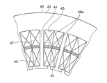
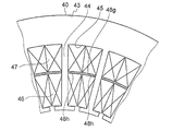
図9に示すように、スロット45内において、2つの第2系統コイル部47は周方向に離間して配置されている。また、磁気干渉低減部材48bは、第1系統コイル部46と第2系統コイル部47との間において周方向に配置されるとともに、2つの第2系統コイル部47同士の離間している部分において径方向外向きに延びて配置されている。すなわち、磁気干渉低減部材48bは、L字型の形状を有している。
次に、この発明の実施の形態4について説明する。この実施の形態4は、実施の形態1に対して磁気干渉低減部材の形状を径方向に伸ばしたものである。
図9に示すように、スロット45内において、2つの第2系統コイル部47は周方向に離間して配置されている。また、磁気干渉低減部材48bは、第1系統コイル部46と第2系統コイル部47との間において周方向に配置されるとともに、2つの第2系統コイル部47同士の離間している部分において径方向外向きに延びて配置されている。すなわち、磁気干渉低減部材48bは、L字型の形状を有している。
同様に、磁気干渉低減部材48cは、第1系統コイル部46と第2系統コイル部47との間において周方向に配置されるとともに、2つの第2系統コイル部47同士の離間している部分において径方向外向きに延びて配置されている。すなわち、磁気干渉低減部材48cは、L字型の形状を有している。
また、磁気干渉低減部材48b及び磁気干渉低減部材48cは、コアバック部43に対してわずかに隙間を有するように配置されている。さらに、磁気干渉低減部材48b及び磁気干渉低減部材48cは、周方向において並べて配置されている。さらにまた、磁気干渉低減部材48b及び磁気干渉低減部材48cの間には隙間が設けられている。
磁気干渉低減部材48b及び磁気干渉低減部材48cが上記のように配置されることにより、磁気干渉低減部材48b及び磁気干渉低減部材48cは第1系統コイル部46と第2系統コイル部47とを径方向に離間して隔絶するとともに、隣り合う第2系統コイル部47同士を周方向に離間して隔絶する。この構成により、第2系統コイル部47の磁束が、磁気干渉低減部材48b及び磁気干渉低減部材48cを通りコアバック部43に鎖交するため、第1系統コイル部46と第2系統コイル部47との磁気干渉率をさらに低減することができる。
このように、磁気干渉低減部材48b及び磁気干渉低減部材48cは、隣り合う第2系統コイル部47同士を周方向に離間するので、第1系統コイル部46と第2系統コイル部47との磁気干渉率をさらに低減することができる。
なお、実施の形態4においては、磁気干渉低減部材48b,48cは、2つの第2系統コイル部47同士の間において径方向に延びて配置されていたが、これ以外の形状であってもよい。例えば、2つの第1系統コイル部46同士の間において径方向内向きに延び、2つの第1系統コイル部46同士を周方向に隔絶していてもよい。
また、この実施の形態4では第1系統コイル部46又は第2系統コイル部47は、固定子40の周方向に離間していたが、厳密に周方向に離間している必要はない。例えば、第1系統コイル部46又は第2系統コイル部47は、周方向に対して斜め方向に離間していてもよい。
実施の形態5.
次に、この発明の実施の形態5について説明する。この実施の形態5は、実施の形態1に対して磁気干渉低減部材の形状を径方向に伸ばしたものである。
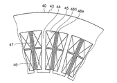
図10に示すように、スロット45内において、隣り合う2つの第1系統コイル部46は周方向に離間して配置されている。また、隣り合う2つの第2系統コイル部47は周方向に離間して配置されている。さらに、磁気干渉低減部材48d及び磁気干渉低減部材48eは、第1系統コイル部46と第2系統コイル部47との間において周方向に配置されるとともに、隣り合う2つの第1系統コイル部46及び隣り合う2つの第2系統コイル部47同士の離間している部分において径方向に延びて配置されている。すなわち、磁気干渉低減部材48d及び磁気干渉低減部材48eは、T字型の形状を有している。
次に、この発明の実施の形態5について説明する。この実施の形態5は、実施の形態1に対して磁気干渉低減部材の形状を径方向に伸ばしたものである。
図10に示すように、スロット45内において、隣り合う2つの第1系統コイル部46は周方向に離間して配置されている。また、隣り合う2つの第2系統コイル部47は周方向に離間して配置されている。さらに、磁気干渉低減部材48d及び磁気干渉低減部材48eは、第1系統コイル部46と第2系統コイル部47との間において周方向に配置されるとともに、隣り合う2つの第1系統コイル部46及び隣り合う2つの第2系統コイル部47同士の離間している部分において径方向に延びて配置されている。すなわち、磁気干渉低減部材48d及び磁気干渉低減部材48eは、T字型の形状を有している。
また、磁気干渉低減部材48d及び磁気干渉低減部材48eは、コアバック部43に対してわずかに隙間を有するように配置されている。さらに、磁気干渉低減部材48d及び磁気干渉低減部材48dは、周方向において並べて配置されている。さらにまた、磁気干渉低減部材48b及び磁気干渉低減部材48cの間には隙間が設けられている。
磁気干渉低減部材48d及び磁気干渉低減部材48eが上記のように配置されることにより、磁気干渉低減部材48d及び磁気干渉低減部材48eは第1系統コイル部46と第2系統コイル部47とを径方向に離間して隔絶するとともに、隣り合う第1系統コイル部46及び隣り合う第2系統コイル部47同士を周方向に離間して隔絶する。この構成により、第2系統コイル部47の磁束が、磁気干渉低減部材48d及び磁気干渉低減部材48eを通るため、第1系統コイル部46と第2系統コイル部47との磁気干渉率をさらに低減する効果を得ることができる。
このように、磁気干渉低減部材48d及び磁気干渉低減部材48eは、隣り合う第1系統コイル部同士と、隣り合う第2系統コイル部47同士とを周方向に離間するので、第1系統コイル部46と第2系統コイル部47との磁気干渉率をさらに低減することができる。
実施の形態6.
次に、この発明の実施の形態6について説明する。この実施の形態6は、実施の形態1に対して第1系統コイル部と第2系統コイル部とを周方向に配置したものである。
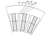
図11に示すように、スロット45に、ティース44に近い側に第1系統コイル部46aが配置されている。また、ティース44から遠い側に第2系統コイル部47aが配置されている。第1系統コイル部46a及び第2系統コイルは固定子40の周方向に配置されている。第1系統コイル部46aと第2系統コイル部47aとは離間しており、その離間している箇所に固定子40の径方向に板状に延びる磁気干渉低減部材48fが配置されている。磁気干渉低減部材48fは、スロット45のコアバック部43の内壁に対してわずかに隙間を有して配置されている。
次に、この発明の実施の形態6について説明する。この実施の形態6は、実施の形態1に対して第1系統コイル部と第2系統コイル部とを周方向に配置したものである。
図11に示すように、スロット45に、ティース44に近い側に第1系統コイル部46aが配置されている。また、ティース44から遠い側に第2系統コイル部47aが配置されている。第1系統コイル部46a及び第2系統コイルは固定子40の周方向に配置されている。第1系統コイル部46aと第2系統コイル部47aとは離間しており、その離間している箇所に固定子40の径方向に板状に延びる磁気干渉低減部材48fが配置されている。磁気干渉低減部材48fは、スロット45のコアバック部43の内壁に対してわずかに隙間を有して配置されている。
すなわち、第1系統コイル部46aと第2系統コイル部47aとは、磁気干渉低減部材48fにより離間して隔絶されている。この第1系統コイル部46aと、磁気干渉低減部材48fと、第2系統コイル部47aとの組み合わせが2つ1組にスロット45に配置されている。その他の構成は実施の形態1と同じである。
第1系統コイル部46aと第2系統コイル部47aとを周方向に並べて配置し、その間に磁気干渉低減部材48fを配置することで、第1系統コイル部46aと第2系統コイル部47aとの相互の磁気干渉率を低減しつつ、磁気干渉低減部材48fが補強材となることにより、固定子40の径方向の剛性を向上させることができるという効果を得ることができる。
なお、実施の形態6では第2系統コイル部47aをティース44から遠い側に配置したが、第1系統コイル部46aをティース44から遠い側に配置してもよい。また、磁気干渉低減部材48fの形状は図10に示す径方向に板状に延びる形状に限定されない。第1系統コイル部46aと第2系統コイル部47aとを離間して隔絶するものであれば、磁気干渉低減部材48fの形状はその他の形状であってもよい。
また、実施の形態6では、第1系統コイル部46aと、磁気干渉低減部材48fと、第2系統コイル部47aとの組み合わせが2つ1組にスロット45に配置されていたが、これ以外の組み合わせであってもよい。例えば、図12に示すように、第1系統コイル部46aと、磁気干渉低減部材48fと、第2系統コイル部47aとの組み合わせが2つ1組に配置されている場合に、この隣り合う組み合わせ同士の間に更に磁気干渉低減部材48fが配置されていてもよい。この構成により、補強材となる磁気干渉低減部材48fの本数が増えるため、固定子40の剛性をさらに向上させることができる。
実施の形態7.
次に、この発明の実施の形態7について説明する。この実施の形態7は、実施の形態1に対して磁気干渉低減部を隣り合うティースに当接させたものである。
図13に示すように、スロット45に配置された磁気干渉低減部材48gの周方向の端部である当接部48hが、固定子40の周方向において隣り合うティース44に当接している。その他の構成は実施の形態1と同じである。
次に、この発明の実施の形態7について説明する。この実施の形態7は、実施の形態1に対して磁気干渉低減部を隣り合うティースに当接させたものである。
図13に示すように、スロット45に配置された磁気干渉低減部材48gの周方向の端部である当接部48hが、固定子40の周方向において隣り合うティース44に当接している。その他の構成は実施の形態1と同じである。
このように、磁気干渉低減部材48gは、固定子40の周方向において、ティース44に当接するため、ティース44と磁気干渉低減部材48gの磁気抵抗が低下する。このため、磁気干渉低減部材48gによる磁気干渉低減効果が大きくなる効果が得られる。また、磁気干渉低減部材48gがティース44に当接することで、固定子40の剛性を高くすることができる効果が得られる。
実施の形態8.
次に、この発明の実施の形態8について説明する。この実施の形態8は、実施の形態6に対して磁気干渉低減部を径方向にティース及びコアバック部に当接させたものである。
図14に示すように、第1系統コイル部46aと第2系統コイル部47aとの間に、径方向に延びる板状の磁気干渉低減部材48jが配置されている。固定子40の径方向の外側において、磁気干渉低減部材48jの端部である当接部48kは、コアバック部43に当接している。また、固定子40の径方向の内側において、磁気干渉低減部材48jの当接部48kは、鍔状の形状であるティース44の先端部44fに当接している。その他の形態は実施の形態6と同じである。
次に、この発明の実施の形態8について説明する。この実施の形態8は、実施の形態6に対して磁気干渉低減部を径方向にティース及びコアバック部に当接させたものである。
図14に示すように、第1系統コイル部46aと第2系統コイル部47aとの間に、径方向に延びる板状の磁気干渉低減部材48jが配置されている。固定子40の径方向の外側において、磁気干渉低減部材48jの端部である当接部48kは、コアバック部43に当接している。また、固定子40の径方向の内側において、磁気干渉低減部材48jの当接部48kは、鍔状の形状であるティース44の先端部44fに当接している。その他の形態は実施の形態6と同じである。
このように、磁気干渉低減部材48gの径方向の当接部48kが、ティース44の先端部44fとコアバック部43との少なくともいずれか一方に当接しているので、ティース44と磁気干渉低減部材48jの磁気抵抗が低下する。このため、磁気干渉低減部材48jによる磁気干渉低減効果が大きくなる効果が得られる。また、固定子40の剛性を高くすることができる効果が得られる。
実施の形態9.
次に、この発明の実施の形態9について説明する。この実施の形態9は、実施の形態1に対して磁気干渉低減部をティースと一体に形成したものである。
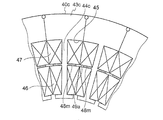
図15に示すように、固定子40cは、複数のコアバック部43cと、コアバック部43cに一体に形成されたティース44cにより構成されている。ティース44cには、第1系統コイル部46及び第2系統コイル部47が巻回されている。このティース44cへの巻回により、隣り合うティース44cの間に形成されるスロット45には、径方向の内側に第1系統コイル部46が配置され、径方向の外側に第2系統コイル部47が配置されている。第1系統コイル部46と第2系統コイル部47との間には、磁気干渉低減部材48mが配置されている。磁気干渉低減部材48mはティース44cと一体に形成されている。また、磁気干渉低減部材48m同士の間には、周方向に間隙49aが形成されている。
次に、この発明の実施の形態9について説明する。この実施の形態9は、実施の形態1に対して磁気干渉低減部をティースと一体に形成したものである。
図15に示すように、固定子40cは、複数のコアバック部43cと、コアバック部43cに一体に形成されたティース44cにより構成されている。ティース44cには、第1系統コイル部46及び第2系統コイル部47が巻回されている。このティース44cへの巻回により、隣り合うティース44cの間に形成されるスロット45には、径方向の内側に第1系統コイル部46が配置され、径方向の外側に第2系統コイル部47が配置されている。第1系統コイル部46と第2系統コイル部47との間には、磁気干渉低減部材48mが配置されている。磁気干渉低減部材48mはティース44cと一体に形成されている。また、磁気干渉低減部材48m同士の間には、周方向に間隙49aが形成されている。
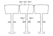
図16に、図15に示す固定子40cについて、積層してコアバック部43c及びティース44cを組み立てる前のコアシート40c1の構成を示す。第1系統コイル部46及び第2系統コイル部47は、まだ配置されていない状態である。コアシート40c1は、隣り合う複数のコアシート40c1間の中央部において周方向に分割された構造を有している。すなわち、コアシート40c1は周方向分割構造を有している。また、各ティース44c1は、周方向に分割された各コアバック部43c1と一体に形成されている。固定子40cを形成するコアシートのティース44c1には、コアシート40c1の周方向に対称に突出する磁気干渉低減部材48m1が形成されている。コアバック部43c1を、隣り合うコアバック部43c1と接合して積層させることで、図15に示す円環状の固定子40cを形成することができる。固定子40cを形成後、ティース44cに、第1系統コイル部46及び第2系統コイル部47を巻回する。その他の構成は実施の形態1と同じである。
このように、固定子40cは、ティース44c毎に周方向に分割され、第1系統コイル部46及び第2系統コイル部47はティース44cに巻回され、固定子40cは円環状に形成される。また、ティース44cと、磁気干渉低減部材48mとは、一体に形成る。そのため、実施の形態1のような形成済みの固定子40が有するティース44に第1系統コイル部46及び第2系統コイル部47を巻回する場合と比較して、ティース44cに第1系統コイル部46及び第2系統コイル部47を巻回することが容易になる利点が得られる。また、周方向分割構造により、固定子40cの製造が容易になる。
実施の形態10.
次に、この発明の実施の形態10について説明する。この実施の形態10は、実施の形態1に対して、隣り合うティースを径方向の内側において結合したものである。
次に、この発明の実施の形態10について説明する。この実施の形態10は、実施の形態1に対して、隣り合うティースを径方向の内側において結合したものである。
図17に示すように、固定子40dには、円環状のコアバック部43dと、コアバック部43dの内周から径方向内側に延びる複数のティース44dが形成されている。コアバック部43dはティース44dとは別体に形成されており、外側鉄心43eを構成している。各ティース44dの径方向内側の鍔部は、隣り合う端部と接合して一体に形成され、ティース44dは全体として内側鉄心44eを構成している。外側鉄心43eと内側鉄心44eは、円弧状の嵌め合い部44gで接合されている。その他の構成は実施の形態1と同じである。
このような構成では、各ティース44dが、隣り合う端部と接合して一体に形成されているので、第1系統コイル部46と第2系統コイル部47との磁気干渉は大きくなる。しかしながら、第1系統コイル部46と第2系統コイル部47との間に、磁気干渉低減部材48が配置されていることで、第1系統コイル部46と第2系統コイル部47と磁気干渉率は低減される。
また、固定子40dが外側鉄心43e及び内側鉄心44eの内外鉄心構造を有し、第1系統コイル部46及び第2系統コイル部47が巻回された内側鉄心44eと、外側鉄心43eとを組み合わせることで、固定子40dを簡単に構成することができ、固定子40dの生産性が向上する。
このように、固定子40dは、複数のティース44dからなる内側鉄心44eと、コアバック部43dからなる外側鉄心43eに分割されており、第1系統コイル部46及び第2系統コイル部47が巻回された内側鉄心44eが、外側鉄心43eと組み合わされて固定子40dが形成される。また、隣り合うティース44dの先端部は互いに連結しているので、磁気干渉率を低減しつつ、固定子40dの生産性を向上することができる。
なお、この実施の形態10では、外側鉄心43eと内側鉄心44eとの嵌め合い部44gの形状は円弧状であったが、この形状に限定されない。例えば、嵌め合い部44gの形状は正八角形などの多角形であってもよい。
実施の形態11.
次に、この発明の実施の形態11について説明する。この実施の形態11は、実施の形態1に対して、磁気干渉低減部材を十字型にしたものである。
図18に示すように、隣り合う第1系統コイル部46及び第2系統コイル部47は、径方向に互いに離間して配置されている。また、隣り合う第1系統コイル部46同士は、周方向に互いに離間して配置されている。さらに、隣り合う第2系統コイル部47同士は、周方向に互いに離間して配置されている。
次に、この発明の実施の形態11について説明する。この実施の形態11は、実施の形態1に対して、磁気干渉低減部材を十字型にしたものである。
図18に示すように、隣り合う第1系統コイル部46及び第2系統コイル部47は、径方向に互いに離間して配置されている。また、隣り合う第1系統コイル部46同士は、周方向に互いに離間して配置されている。さらに、隣り合う第2系統コイル部47同士は、周方向に互いに離間して配置されている。
上記のように各第1系統コイル部46及び各第2系統コイル部47が、それぞれ離間している箇所に、磁気干渉低減部材48pが配置されている。磁気干渉低減部材48pは、十字型に形成されている。その他の構成は実施の形態1と同じである。
このように、各第1系統コイル部46及び各第2系統コイル部47の磁気干渉率を低減しつつ、固定子40の剛性を確保することができる。
実施の形態12.
次に、この発明の実施の形態12について説明する。この実施の形態12は、実施の形態1に対して、第1系統コイル部及び各第2系統コイル部のうち、同相間にのみ磁気干渉低減部材を挿入するものである。
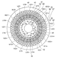
図19に示すように、固定子40は24個のティース44を有している。また、回転子50の極数は20個である。第1系統コイル部46に配置されるコイルは、時計回りに、U11+、U12-、W11-、W12+、V11+、V12-、U13-、U14+、W13+、W14-、V13-、V14+、U15+、U16-、W15-、W16+、V15+、V16-、U17-、U18+、W17+、W18-、V17-、V18+の各相の順に配置されており、第1系統電力供給源20に接続されている。
次に、この発明の実施の形態12について説明する。この実施の形態12は、実施の形態1に対して、第1系統コイル部及び各第2系統コイル部のうち、同相間にのみ磁気干渉低減部材を挿入するものである。
図19に示すように、固定子40は24個のティース44を有している。また、回転子50の極数は20個である。第1系統コイル部46に配置されるコイルは、時計回りに、U11+、U12-、W11-、W12+、V11+、V12-、U13-、U14+、W13+、W14-、V13-、V14+、U15+、U16-、W15-、W16+、V15+、V16-、U17-、U18+、W17+、W18-、V17-、V18+の各相の順に配置されており、第1系統電力供給源20に接続されている。
また、第2系統コイル部47に配置されるコイルは、時計回りに、U21+、U22-、W21-、W22+、V21+、V22-、U23-、U24+、W23+、W24-、V23-、V24+、U25+、U26-、W25-、W26+、V25+、V26-、U27-、U28+、W27+、W28-、V27-、V28+の各相の順に配置されている。
各スロット45内において、同相の巻線が配置されるスロット45においては、第1系統コイル部46と第2系統コイル部47との間に磁気干渉低減部材48を配置する。具体的には、U11+及びU21+、W11-及びW21-、V11+及びV21+、U13-及びU23-、W13+及びW23+、V13-及びV23-、U15+及びU25+、W15-及びW25-、V15+及びV25+、U17-及びU27-、W17+及びW27-、V18+及びV28-の間にそれぞれ磁気干渉低減部材48を配置する。すなわち、各スロット45において、1つおきに第1系統コイル部46と第2系統コイル部47との間に磁気干渉低減部材48を配置する。
このように同一のスロット45に配置された、第1系統コイル部46と第2系統コイル部47とが同相の場合に、第1系統コイル部46と第2系統コイル部47との間に磁気干渉低減部材48を配置することにより、第1系統コイル部46と第2系統コイル部47との磁気干渉率を低減しつつ、漏れ磁束を低減することができる。これにより、回転電機10のトルク低下を抑制する効果が得られる。
実施の形態13.
次に、この発明の実施の形態13について説明する。この実施の形態13は、実施の形態1に対して、第1系統コイル部を、スロットの径方向内側及び径方向外側に交互に配置する。また、第2系統コイル部を、スロットの径方向外側及び径方向内側に交互に配置したものである。
図20に示すように、固定子40は24個のティース44を有している。また、回転子50の極数は20個である。第1系統コイル部46に配置されるコイルは、時計回りに、U11+、U22-、W11-、W22+、V11+、V22-、U13-、U24+、W13+、W24-、V13-、V24+、U15+、U26-、W15-、W26+、V15+、V26-、U17-、U28+、W17+、W28-、V17-、V28+の各相の順に配置されている。
次に、この発明の実施の形態13について説明する。この実施の形態13は、実施の形態1に対して、第1系統コイル部を、スロットの径方向内側及び径方向外側に交互に配置する。また、第2系統コイル部を、スロットの径方向外側及び径方向内側に交互に配置したものである。
図20に示すように、固定子40は24個のティース44を有している。また、回転子50の極数は20個である。第1系統コイル部46に配置されるコイルは、時計回りに、U11+、U22-、W11-、W22+、V11+、V22-、U13-、U24+、W13+、W24-、V13-、V24+、U15+、U26-、W15-、W26+、V15+、V26-、U17-、U28+、W17+、W28-、V17-、V28+の各相の順に配置されている。
また、第2系統コイル部47に配置されるコイルは、時計回りに、U21+、U12-、W21-、W12+、V21+、V12-、U23-、U14+、W23+、W14-、V23-、V14+、U25+、U16-、W25-、W16+、V25+、V16-、U27-、U18+、W27+、W18-、V27-、V18+の各相の順に配置されている。
ここで、U11+、U12-、W11-、W12+、V11+、V12-、U13-、U14+、W13+、W14-、V13-、V14+、U15+、U16-、W15-、W16+、V15+、V16-、U17-、U18+、W17+、W18-、V17-、V18+のコイルは、第1巻線系統群のコイルであり、第1系統電力供給源20に接続されている。
また、U21+、U22-、W21-、W22+、V21+、V22-、U23-、U24+、W23+、W24-、V23-、V24+、U25+、U26-、W25-、W26+、V25+、V26-、U27-、U28+、W27+、W28-、V27-、V28+のコイルは、第2巻線系統群のコイルであり、第2系統電力供給源30に接続されている。
すなわち、固定子40のスロット45には、第1系統コイル部46に第1巻線系統群のコイルが配置され、第2系統コイル部47に第2巻線系統群のコイルが配置される。そして、このスロット45に隣接するスロットには、第1系統コイル部46に第2巻線系統群のコイルが配置され、第2系統コイル部47に第1巻線系統群のコイルが配置されたスロット45が配置される。したがって、隣接するスロット45の間で、第1巻線系統群及び第2巻線系統群のコイルの、径方向における位置関係が異なる。また、隣接するスロットの45間で、第1巻線系統群及び第2巻線系統群の、周方向のコイルの位置関係が異なってもよい。
このように、隣り合う各ティース44間には、ティース44に巻回された第1系統コイル部46及び第2系統コイル部47が配置されるスロット45を有し、同一のスロット45に配置された、第1巻線系統群と第2巻線系統群との、固定子40における径方向又は周方向の位置関係が、スロット45毎に異なる。このために、第1巻線系統群及び第2巻線系統群の漏れ磁束が等しくなり、インダクタンスが等しくなるため、さらに制御性を向上することができる効果を得ることができる。
なお、この実施の形態13では固定子40は24個のティース44を有しており、回転子50の極数は20個であったが、これ以外の固定子のティースの数及び回転子の極数であってもよい。
実施の形態14.
次に、この発明の実施の形態14について説明する。この実施の形態14は、実施の形態1~13の回転電機10を自動車の電動パワーステアリング装置に用いたものである。
図21に示す、自動車の電動パワーステアリング装置200について説明する。運転者が図示しないステアリングホイールを操舵し、その操舵トルクが図示しないステアリング装置を介して入力センサ201に伝達される。また、トルクセンサ202はこのトルクを検出して第1系統電力供給源20及び第2系統電力供給源30に入力する。なお、第1系統電力供給源20及び第2系統電力供給源30は、電源コネクタ28,38(第1系統コネクタ及び第2系統コネクタ)を介して図示しないバッテリから電力を供給される。
次に、この発明の実施の形態14について説明する。この実施の形態14は、実施の形態1~13の回転電機10を自動車の電動パワーステアリング装置に用いたものである。
図21に示す、自動車の電動パワーステアリング装置200について説明する。運転者が図示しないステアリングホイールを操舵し、その操舵トルクが図示しないステアリング装置を介して入力センサ201に伝達される。また、トルクセンサ202はこのトルクを検出して第1系統電力供給源20及び第2系統電力供給源30に入力する。なお、第1系統電力供給源20及び第2系統電力供給源30は、電源コネクタ28,38(第1系統コネクタ及び第2系統コネクタ)を介して図示しないバッテリから電力を供給される。
また、例えば車速のような自動車の情報が、第1系統電力供給源20及び第2系統電力供給源30に入力される。第1系統電力供給源20及び第2系統電力供給源30は、操舵トルク及び例えば車速のような自動車の情報から、必要なアシストトルクを算出し、永久磁石型の回転電機10に電力を供給する。回転電機10は、図示しないラック軸の移動方向Aに平行な向きに配置される。
回転電機10が発生させたトルクは、図示しないベルト及びボールねじが内蔵されたギアボックス203に伝達される。そして、回転電機10が発生させたトルクはギアボックス203により減速されて、ハウジングの内部に設けられているラック軸204を移動方向Aに移動させる。これにより、タイロッド206が動き、運転者の操舵力を補助して自動車のタイヤを転舵させる。そのため、運転者は少ない力で車両を旋回させることができる。
このような電動パワーステアステアリング装置では、回転電機10が発生させるコギングトルク、トルクリップルは図示しないステアリング装置のギアを介して運転者に伝達される。そのため、良好な操舵感覚を得るためには、コギングトルク、トルクリップルが小さいことが望ましい。また、回転電機10の振動、騒音も小さい方が望ましい。
そこで、この発明の実施の形態1~13の回転電機10を自動車の電動パワーステアリング装置200に用いることで、特に、電動パワーステアリング装置200の巻線群又は第1系統電力供給源20a、第2系統電力供給源30aが故障した場合であっても、運転者の操舵力を安定して補助することができる。また、正常時には、安定した制御性及び快適な操舵管を得ることができるという利点を有する。
このように、上記回転電機10を有する電動パワーステアリング装置200は、故障時に運転者の操舵力を安定して補助することができる。また、正常時には、安定した制御性及び快適な操舵管を得ることができるという利点を有する。
なお、この実施の形態1~13では固定子40,40a,40b,40c,40dは24個のティース44を有しており、回転子50の極数は20個であったが、これ以外の固定子のティースの数及び回転子の極数であってもよい。また、この実施の形態1~13では、固定子40,40a,40b,40c,40dは第1系統コイル部と第2系統コイル部を有していたが、さらに別の系統のコイル部を有していてもよい。
10 回転電機、40,40a,40b,40c,40d 固定子、43,43c,43d コアバック部、43e 外側鉄心、44,44a,44b,44c,44d ティース、44e 内側鉄心、44f 先端部、45 スロット、46,46a,46b,46U 第1系統コイル部、47,47a,47b,47U 第2系統コイル部、48,48a,48b,48c,48d,48e,48f,48g,48j,48m,48p 磁気干渉低減部材。
Claims (13)
- 円環状の固定子を備える回転電機であって、
前記固定子は、
コアバック部と、
前記コアバック部から径方向の内側に延びる複数のティースと、
隣り合う前記ティースの間に形成されたスロットと、
前記ティース毎に巻回され、前記スロット毎に配置された複数の巻線群と、
隣り合う前記巻線群を離間させるように配置され、前記巻線群の間の磁気干渉を低減する磁気干渉低減部材と
を有する回転電機。 - 前記磁気干渉低減部材は、前記固定子の周方向において、前記ティースに当接する請求項1に記載の回転電機。
- 前記磁気干渉低減部材は、前記ティースの先端部と前記コアバック部との少なくともいずれか一方に当接する請求項1又は2に記載の回転電機。
- 前記複数の巻線群は2つの巻線群からなり、
一方の前記巻線群に印加される電流値は、他方の前記巻線群に印加される電流値よりも大きい請求項1~3のいずれか1項に記載の回転電機。 - 前記複数の巻線群は2つの巻線群からなり、
一方の前記巻線群の巻数は、他方の前記巻線群の巻数より大きい請求項1~4のいずれか1項に記載の回転電機。 - 前記複数の巻線群は2つの巻線群からなり、
同一の前記スロットに配置された、一方の前記巻線群と他方の前記巻線群とが同相の場合に、一方の前記巻線群と他方の前記巻線群との間に前記磁気干渉低減部材を設ける請求項1~5のいずれか1項に記載の回転電機。 - 前記複数の巻線群は2つの巻線群からなり、
同一の前記スロットに配置された、一方の前記巻線群と他方の前記巻線群との、前記固定子における径方向又は周方向の位置関係が、前記スロット毎に異なる請求項1~6のいずれか1項に記載の回転電機。 - 前記固定子は、前記複数のティースからなる内側鉄心と、前記コアバック部からなる外側鉄心に分割されており、
前記巻線群が巻回された前記内側鉄心が、前記外側鉄心と組み合わされて前記固定子が形成される請求項1~7のいずれか一項に記載の回転電機。 - 隣り合う前記ティースの先端部は、互いに連結している請求項1~8のいずれか1項に記載の回転電機。
- 前記固定子は、前記ティース毎に周方向に分割され、
前記巻線群は前記ティースに巻回され、前記固定子は円環状に形成される請求項1~7のいずれか一項に記載の回転電機。 - 前記ティースと、前記磁気干渉低減部材とは、一体に形成される請求項1~10のいずれか1項に記載の回転電機。
- 前記磁気干渉低減部材は、前記ティース及び前記コアバック部とは別体として設けられている請求項1~10のいずれか1項に記載の回転電機。
- 請求項1~12のいずれか一項に記載の回転電機を有する電動パワーステアリング装置。
Priority Applications (4)
| Application Number | Priority Date | Filing Date | Title |
|---|---|---|---|
| CN201980022308.7A CN111919362A (zh) | 2018-04-09 | 2019-03-20 | 旋转电机及具有旋转电机的电动助力转向装置 |
| JP2019548491A JP6612010B1 (ja) | 2018-04-09 | 2019-03-20 | 回転電機及び回転電機を有する電動パワーステアリング装置 |
| EP19784848.4A EP3780355A4 (en) | 2018-04-09 | 2019-03-20 | ELECTRIC LATHE AND ELECTRIC POWER STEERING WITH ELECTRIC LATHE USE |
| US17/044,677 US20210075273A1 (en) | 2018-04-09 | 2019-03-20 | Rotating electric machine and electric power steering device having rotating electric machine |
Applications Claiming Priority (2)
| Application Number | Priority Date | Filing Date | Title |
|---|---|---|---|
| JP2018074939 | 2018-04-09 | ||
| JP2018-074939 | 2018-04-09 |
Publications (1)
| Publication Number | Publication Date |
|---|---|
| WO2019198451A1 true WO2019198451A1 (ja) | 2019-10-17 |
Family
ID=68164046
Family Applications (1)
| Application Number | Title | Priority Date | Filing Date |
|---|---|---|---|
| PCT/JP2019/011796 Ceased WO2019198451A1 (ja) | 2018-04-09 | 2019-03-20 | 回転電機及び回転電機を有する電動パワーステアリング装置 |
Country Status (5)
| Country | Link |
|---|---|
| US (1) | US20210075273A1 (ja) |
| EP (1) | EP3780355A4 (ja) |
| JP (1) | JP6612010B1 (ja) |
| CN (1) | CN111919362A (ja) |
| WO (1) | WO2019198451A1 (ja) |
Cited By (2)
| Publication number | Priority date | Publication date | Assignee | Title |
|---|---|---|---|---|
| JP2021069197A (ja) * | 2019-10-24 | 2021-04-30 | 日立Astemo株式会社 | モータ制御装置、並びにそれを用いた電動パワーステアリング装置 |
| EP3883089A1 (en) * | 2020-03-19 | 2021-09-22 | Siemens Gamesa Renewable Energy A/S | End of segment mechanical coil protection |
Citations (13)
| Publication number | Priority date | Publication date | Assignee | Title |
|---|---|---|---|---|
| JPS55151104A (en) * | 1979-05-12 | 1980-11-25 | Daimler Benz Ag | Cylinder head for internal combustion engine |
| JP2002186205A (ja) * | 2000-12-14 | 2002-06-28 | Nissan Motor Co Ltd | 回転電機 |
| JP2002186211A (ja) * | 2000-12-14 | 2002-06-28 | Nissan Motor Co Ltd | 回転電機および回転電機の製造方法 |
| JP2004180449A (ja) * | 2002-11-28 | 2004-06-24 | Asmo Co Ltd | パワーステアリング装置用ブラシレスモータ |
| EP2136455A1 (en) * | 2008-06-19 | 2009-12-23 | Abb Research Ltd. | An electric motor provided with a cooling arrangement |
| JP2010081715A (ja) * | 2008-09-25 | 2010-04-08 | Toshiba Mitsubishi-Electric Industrial System Corp | 回転電機 |
| JP2010220387A (ja) * | 2009-03-17 | 2010-09-30 | Toyota Motor Corp | ステータ |
| JP2013111734A (ja) | 2011-11-30 | 2013-06-10 | Hitachi Koki Co Ltd | 電動工具 |
| JP2014033495A (ja) * | 2012-08-01 | 2014-02-20 | Toyota Motor Corp | 回転電機のステータ |
| JP2014176215A (ja) * | 2013-03-08 | 2014-09-22 | Nsk Ltd | モータ制御装置、これを使用した電動パワーステアリング装置及び車両 |
| WO2015011939A1 (ja) * | 2013-07-24 | 2015-01-29 | 三菱電機株式会社 | 固定子鉄心、固定子、固定子の製造方法、回転電機、電動パワーステアリング装置 |
| WO2016132450A1 (ja) * | 2015-02-17 | 2016-08-25 | 三菱電機株式会社 | 永久磁石式三相二重化モータおよび電動パワーステアリング装置 |
| WO2017168574A1 (ja) * | 2016-03-29 | 2017-10-05 | 三菱電機株式会社 | 電動機 |
Family Cites Families (2)
| Publication number | Priority date | Publication date | Assignee | Title |
|---|---|---|---|---|
| JPS5774685U (ja) * | 1980-10-24 | 1982-05-08 | ||
| WO2017163523A1 (ja) * | 2016-03-24 | 2017-09-28 | 三菱電機株式会社 | 回転電機、電動パワーステアリング装置および回転電機の製造方法 |
-
2019
- 2019-03-20 EP EP19784848.4A patent/EP3780355A4/en not_active Withdrawn
- 2019-03-20 CN CN201980022308.7A patent/CN111919362A/zh not_active Withdrawn
- 2019-03-20 US US17/044,677 patent/US20210075273A1/en not_active Abandoned
- 2019-03-20 WO PCT/JP2019/011796 patent/WO2019198451A1/ja not_active Ceased
- 2019-03-20 JP JP2019548491A patent/JP6612010B1/ja active Active
Patent Citations (13)
| Publication number | Priority date | Publication date | Assignee | Title |
|---|---|---|---|---|
| JPS55151104A (en) * | 1979-05-12 | 1980-11-25 | Daimler Benz Ag | Cylinder head for internal combustion engine |
| JP2002186205A (ja) * | 2000-12-14 | 2002-06-28 | Nissan Motor Co Ltd | 回転電機 |
| JP2002186211A (ja) * | 2000-12-14 | 2002-06-28 | Nissan Motor Co Ltd | 回転電機および回転電機の製造方法 |
| JP2004180449A (ja) * | 2002-11-28 | 2004-06-24 | Asmo Co Ltd | パワーステアリング装置用ブラシレスモータ |
| EP2136455A1 (en) * | 2008-06-19 | 2009-12-23 | Abb Research Ltd. | An electric motor provided with a cooling arrangement |
| JP2010081715A (ja) * | 2008-09-25 | 2010-04-08 | Toshiba Mitsubishi-Electric Industrial System Corp | 回転電機 |
| JP2010220387A (ja) * | 2009-03-17 | 2010-09-30 | Toyota Motor Corp | ステータ |
| JP2013111734A (ja) | 2011-11-30 | 2013-06-10 | Hitachi Koki Co Ltd | 電動工具 |
| JP2014033495A (ja) * | 2012-08-01 | 2014-02-20 | Toyota Motor Corp | 回転電機のステータ |
| JP2014176215A (ja) * | 2013-03-08 | 2014-09-22 | Nsk Ltd | モータ制御装置、これを使用した電動パワーステアリング装置及び車両 |
| WO2015011939A1 (ja) * | 2013-07-24 | 2015-01-29 | 三菱電機株式会社 | 固定子鉄心、固定子、固定子の製造方法、回転電機、電動パワーステアリング装置 |
| WO2016132450A1 (ja) * | 2015-02-17 | 2016-08-25 | 三菱電機株式会社 | 永久磁石式三相二重化モータおよび電動パワーステアリング装置 |
| WO2017168574A1 (ja) * | 2016-03-29 | 2017-10-05 | 三菱電機株式会社 | 電動機 |
Non-Patent Citations (1)
| Title |
|---|
| See also references of EP3780355A4 * |
Cited By (4)
| Publication number | Priority date | Publication date | Assignee | Title |
|---|---|---|---|---|
| JP2021069197A (ja) * | 2019-10-24 | 2021-04-30 | 日立Astemo株式会社 | モータ制御装置、並びにそれを用いた電動パワーステアリング装置 |
| JP7249261B2 (ja) | 2019-10-24 | 2023-03-30 | 日立Astemo株式会社 | モータ制御装置、並びにそれを用いた電動パワーステアリング装置 |
| EP3883089A1 (en) * | 2020-03-19 | 2021-09-22 | Siemens Gamesa Renewable Energy A/S | End of segment mechanical coil protection |
| WO2021185493A1 (en) * | 2020-03-19 | 2021-09-23 | Siemens Gamesa Renewable Energy A/S | End of segment mechanical coil protection |
Also Published As
| Publication number | Publication date |
|---|---|
| CN111919362A (zh) | 2020-11-10 |
| JPWO2019198451A1 (ja) | 2020-04-30 |
| JP6612010B1 (ja) | 2019-11-27 |
| US20210075273A1 (en) | 2021-03-11 |
| EP3780355A1 (en) | 2021-02-17 |
| EP3780355A4 (en) | 2021-06-09 |
Similar Documents
| Publication | Publication Date | Title |
|---|---|---|
| JP6415746B2 (ja) | 回転電機 | |
| JP6211227B2 (ja) | 回転電機 | |
| US9124159B2 (en) | Electromagnetic rotary electric machine | |
| JP5299679B2 (ja) | モータジェネレータ | |
| JP5880793B1 (ja) | 電動機、電動パワーステアリング装置および車両 | |
| US6949856B2 (en) | Permanent magnet rotating electric machine and electrically driven vehicle employing same | |
| JP5930131B2 (ja) | 電動機制御装置、電動パワーステアリング装置および車両 | |
| JP6636184B2 (ja) | 電動駆動装置および電動パワーステアリング装置 | |
| WO2013161474A1 (ja) | 永久磁石回転電機及びそれを用いた電動車両 | |
| US20220166298A1 (en) | Rotary motor and robot | |
| JP6612010B1 (ja) | 回転電機及び回転電機を有する電動パワーステアリング装置 | |
| WO2014188757A1 (ja) | 回転電機の回転子、回転電機、電動駆動システム、及び電動車両 | |
| JP2010011611A (ja) | 永久磁石型回転電機およびパワーステアリング装置 | |
| JP5221895B2 (ja) | シンクロナスリラクタンスモータ | |
| JP2010110166A (ja) | アキシャルギャップ型回転電機 | |
| JP3638871B2 (ja) | 自動車用の永久磁石回転電機及び自動車 | |
| JP4501683B2 (ja) | 永久磁石回転電機及びそれを用いた車載電動アクチュエータ装置用電機システム並びに電動パワーステアリング装置用電機システム | |
| JP6788957B2 (ja) | 発電機 | |
| JP5708566B2 (ja) | 電磁カップリング | |
| JP3681332B2 (ja) | 自動車用の永久磁石回転電機及び自動車 | |
| WO2018180448A1 (ja) | ステータ、モータ、電動パワーステアリング装置 | |
| JP2018207651A (ja) | ブラシレスモータ及び電動パワーステアリング装置用モータ | |
| JP5114135B2 (ja) | アキシャルギャップ型モータ | |
| JP5440670B2 (ja) | 電動機 | |
| JP2016146713A (ja) | 発電機 |
Legal Events
| Date | Code | Title | Description |
|---|---|---|---|
| ENP | Entry into the national phase |
Ref document number: 2019548491 Country of ref document: JP Kind code of ref document: A |
|
| 121 | Ep: the epo has been informed by wipo that ep was designated in this application |
Ref document number: 19784848 Country of ref document: EP Kind code of ref document: A1 |
|
| NENP | Non-entry into the national phase |
Ref country code: DE |
|
| ENP | Entry into the national phase |
Ref document number: 2019784848 Country of ref document: EP Effective date: 20201109 |