WO2019198532A1 - 物体検出装置、物体検出システム、及び物体検出方法 - Google Patents
物体検出装置、物体検出システム、及び物体検出方法 Download PDFInfo
- Publication number
- WO2019198532A1 WO2019198532A1 PCT/JP2019/013640 JP2019013640W WO2019198532A1 WO 2019198532 A1 WO2019198532 A1 WO 2019198532A1 JP 2019013640 W JP2019013640 W JP 2019013640W WO 2019198532 A1 WO2019198532 A1 WO 2019198532A1
- Authority
- WO
- WIPO (PCT)
- Prior art keywords
- processing
- radar
- object detection
- cell
- grid
- Prior art date
- Legal status (The legal status is an assumption and is not a legal conclusion. Google has not performed a legal analysis and makes no representation as to the accuracy of the status listed.)
- Ceased
Links
Images








Classifications
-
- G—PHYSICS
- G01—MEASURING; TESTING
- G01S—RADIO DIRECTION-FINDING; RADIO NAVIGATION; DETERMINING DISTANCE OR VELOCITY BY USE OF RADIO WAVES; LOCATING OR PRESENCE-DETECTING BY USE OF THE REFLECTION OR RERADIATION OF RADIO WAVES; ANALOGOUS ARRANGEMENTS USING OTHER WAVES
- G01S7/00—Details of systems according to groups G01S13/00, G01S15/00, G01S17/00
- G01S7/02—Details of systems according to groups G01S13/00, G01S15/00, G01S17/00 of systems according to group G01S13/00
- G01S7/41—Details of systems according to groups G01S13/00, G01S15/00, G01S17/00 of systems according to group G01S13/00 using analysis of echo signal for target characterisation; Target signature; Target cross-section
-
- G—PHYSICS
- G01—MEASURING; TESTING
- G01S—RADIO DIRECTION-FINDING; RADIO NAVIGATION; DETERMINING DISTANCE OR VELOCITY BY USE OF RADIO WAVES; LOCATING OR PRESENCE-DETECTING BY USE OF THE REFLECTION OR RERADIATION OF RADIO WAVES; ANALOGOUS ARRANGEMENTS USING OTHER WAVES
- G01S13/00—Systems using the reflection or reradiation of radio waves, e.g. radar systems; Analogous systems using reflection or reradiation of waves whose nature or wavelength is irrelevant or unspecified
- G01S13/66—Radar-tracking systems; Analogous systems
- G01S13/72—Radar-tracking systems; Analogous systems for two-dimensional [2D] tracking, e.g. combination of angle and range tracking, track-while-scan radar
- G01S13/723—Radar-tracking systems; Analogous systems for two-dimensional [2D] tracking, e.g. combination of angle and range tracking, track-while-scan radar by using numerical data
- G01S13/726—Multiple target tracking
-
- G—PHYSICS
- G01—MEASURING; TESTING
- G01S—RADIO DIRECTION-FINDING; RADIO NAVIGATION; DETERMINING DISTANCE OR VELOCITY BY USE OF RADIO WAVES; LOCATING OR PRESENCE-DETECTING BY USE OF THE REFLECTION OR RERADIATION OF RADIO WAVES; ANALOGOUS ARRANGEMENTS USING OTHER WAVES
- G01S13/00—Systems using the reflection or reradiation of radio waves, e.g. radar systems; Analogous systems using reflection or reradiation of waves whose nature or wavelength is irrelevant or unspecified
- G01S13/003—Bistatic radar systems; Multistatic radar systems
-
- G—PHYSICS
- G01—MEASURING; TESTING
- G01S—RADIO DIRECTION-FINDING; RADIO NAVIGATION; DETERMINING DISTANCE OR VELOCITY BY USE OF RADIO WAVES; LOCATING OR PRESENCE-DETECTING BY USE OF THE REFLECTION OR RERADIATION OF RADIO WAVES; ANALOGOUS ARRANGEMENTS USING OTHER WAVES
- G01S13/00—Systems using the reflection or reradiation of radio waves, e.g. radar systems; Analogous systems using reflection or reradiation of waves whose nature or wavelength is irrelevant or unspecified
- G01S13/87—Combinations of radar systems, e.g. primary radar and secondary radar
-
- G—PHYSICS
- G01—MEASURING; TESTING
- G01S—RADIO DIRECTION-FINDING; RADIO NAVIGATION; DETERMINING DISTANCE OR VELOCITY BY USE OF RADIO WAVES; LOCATING OR PRESENCE-DETECTING BY USE OF THE REFLECTION OR RERADIATION OF RADIO WAVES; ANALOGOUS ARRANGEMENTS USING OTHER WAVES
- G01S13/00—Systems using the reflection or reradiation of radio waves, e.g. radar systems; Analogous systems using reflection or reradiation of waves whose nature or wavelength is irrelevant or unspecified
- G01S13/88—Radar or analogous systems specially adapted for specific applications
- G01S13/91—Radar or analogous systems specially adapted for specific applications for traffic control
-
- G—PHYSICS
- G01—MEASURING; TESTING
- G01S—RADIO DIRECTION-FINDING; RADIO NAVIGATION; DETERMINING DISTANCE OR VELOCITY BY USE OF RADIO WAVES; LOCATING OR PRESENCE-DETECTING BY USE OF THE REFLECTION OR RERADIATION OF RADIO WAVES; ANALOGOUS ARRANGEMENTS USING OTHER WAVES
- G01S13/00—Systems using the reflection or reradiation of radio waves, e.g. radar systems; Analogous systems using reflection or reradiation of waves whose nature or wavelength is irrelevant or unspecified
- G01S13/88—Radar or analogous systems specially adapted for specific applications
- G01S13/93—Radar or analogous systems specially adapted for specific applications for anti-collision purposes
- G01S13/931—Radar or analogous systems specially adapted for specific applications for anti-collision purposes of land vehicles
-
- G—PHYSICS
- G01—MEASURING; TESTING
- G01S—RADIO DIRECTION-FINDING; RADIO NAVIGATION; DETERMINING DISTANCE OR VELOCITY BY USE OF RADIO WAVES; LOCATING OR PRESENCE-DETECTING BY USE OF THE REFLECTION OR RERADIATION OF RADIO WAVES; ANALOGOUS ARRANGEMENTS USING OTHER WAVES
- G01S7/00—Details of systems according to groups G01S13/00, G01S15/00, G01S17/00
- G01S7/02—Details of systems according to groups G01S13/00, G01S15/00, G01S17/00 of systems according to group G01S13/00
- G01S7/28—Details of pulse systems
- G01S7/285—Receivers
- G01S7/295—Means for transforming co-ordinates or for evaluating data, e.g. using computers
- G01S7/2955—Means for determining the position of the radar coordinate system for evaluating the position data of the target in another coordinate system
-
- G—PHYSICS
- G08—SIGNALLING
- G08G—TRAFFIC CONTROL SYSTEMS
- G08G1/00—Traffic control systems for road vehicles
- G08G1/01—Detecting movement of traffic to be counted or controlled
- G08G1/0104—Measuring and analyzing of parameters relative to traffic conditions
- G08G1/0108—Measuring and analyzing of parameters relative to traffic conditions based on the source of data
- G08G1/0116—Measuring and analyzing of parameters relative to traffic conditions based on the source of data from roadside infrastructure, e.g. beacons
Definitions
- the present disclosure relates to an object detection device, an object detection system, and an object detection method for detecting an object based on radar measurement information.
- Non-Patent Document 1 a method using DBSCAN (Density-Based Spatial Clustering of Applications with Noise) as a clustering algorithm is widely used (see Non-Patent Document 1).
- a combined relative velocity vector of a virtual object including each measurement point is calculated based on each relative velocity vector of a plurality of measurement points.
- a radar signal processing apparatus that groups virtual objects having the same composite relative velocity vector of the calculated virtual objects as real objects is known (see Patent Document 1).
- a plurality of radars are arranged at two positions on the left and right in front of the vehicle, and the detection results of the plurality of radars with respect to the same position of the virtual object (left and right relative speeds).
- the vector component By obtaining the vector component), the combined relative velocity vector of the virtual object is obtained.
- each radar is connected to one side of the object (for example, the front part). ) And the other side (for example, the rear part), respectively, it is difficult to obtain measurement points relating to the same position of the detection target by each radar.
- the present disclosure has been devised in view of the above-described problems of the prior art, and provides an object detection device, an object detection system, and an object detection method capable of performing appropriate clustering on radar measurement information.
- the main purpose is to provide.
- the object detection device of the present disclosure is an object detection device including a processor that executes processing for detecting an object based on measurement information of one or more radars, and the processor is provided in a measurement area of each radar.
- Clustering processing that is set in correspondence with each other and obtains setting information of a radar grid for measurement composed of a plurality of radar cells and is configured corresponding to the measurement area and composed of a plurality of processing cells.
- processing grid setting information for each, based on the distance between each of the radar cells and each of the processing cells, to calculate the likelihood for the measurement value of each radar cell, respectively, based on the likelihood, Calculating a grid value of each processing cell in the processing grid, and for each processing cell, a distance between the processing cells or the grid value; Rui is configured to perform clustering based on both of the grid values and the distance.
- the object detection system includes the object detection device and the one or more radars.
- the object detection method of the present disclosure is an object detection method by an object detection apparatus that executes processing for detecting an object based on measurement information of one or more radars, and corresponds to the measurement area of each radar. And setting information of a radar grid for measurement composed of a plurality of radar cells, and for clustering processing configured corresponding to the measurement area and composed of a plurality of processing cells. Obtain processing grid setting information, calculate the likelihood for each radar cell based on the distance between each radar cell and each processing cell, and based on the likelihood, The grid value of each processing cell in the grid is calculated, and for each processing cell, the distance between the processing cells or the grid value, or the previous Distance between a configuration that performs clustering on the basis of both of the grid values.
- 1 is an overall configuration diagram of an object detection system 1 according to a first embodiment.
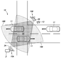
- Explanatory drawing which shows the example of application of the object detection system 1 which concerns on 1st Embodiment.
- the block diagram which shows schematic structure of the object detection apparatus 3 which concerns on 1st Embodiment.
- Explanatory drawing which shows an example of the grating
- Explanatory drawing which shows an example of the likelihood calculation method by the object detection apparatus 3 which concerns on 1st Embodiment.
- Explanatory drawing which shows an example of the likelihood calculation method by the object detection apparatus 3 which concerns on 1st Embodiment.
- Explanatory drawing which shows an example of the likelihood calculation method by the object detection apparatus 3 which concerns on 1st Embodiment.
- Explanatory drawing which shows the outline
- Explanatory drawing which shows the information output result by the object detection apparatus 3 which concerns on 1st Embodiment.
- the flowchart which shows the operation
- the flowchart which shows the operation
- Explanatory drawing which shows the outline
- the flowchart which shows the operation
- a first invention made to solve the above-mentioned problem is an object detection apparatus including a processor that executes a process for detecting an object based on measurement information of one or more radars.
- the setting information of the radar grid for measurement which is set corresponding to each measurement area of each radar and composed of a plurality of radar cells, is acquired, set corresponding to the measurement area, and used for a plurality of processes.
- clustering of processing cells is performed based on a lattice value that takes into account the likelihood calculated based on the distance between each radar cell and each processing cell, and therefore it is possible to perform appropriate clustering on radar measurement information. It becomes possible.
- the processor when a plurality of likelihoods are calculated based on a distance between each radar cell and one processing grid, the processor processes the maximum value of the plurality of likelihoods.
- the grid value is calculated as the grid value of the grid for use.
- the processor calculates the sum of the plurality of likelihoods in the processing.
- the grid value is calculated as the grid value of the grid for use.
- the fourth invention is configured such that the processor calculates the likelihood related to the measurement value of each radar cell based on the reflection intensity related to each radar cell.
- the fifth invention is configured such that the processor calculates the likelihood related to the measurement value of each radar cell based on the Doppler velocity related to each radar cell.
- the sixth invention is configured such that the processor performs the clustering based on a difference of the lattice values in a pair of processing lattices to be processed.
- the seventh invention is configured such that the distance between each radar cell and each processing cell is a distance between the centers of those cells.
- the distance between each radar cell and each processing cell can be calculated easily and appropriately.
- the radar grating is configured based on polar coordinates
- the processing grid is configured based on orthogonal coordinates
- the ninth invention is an object detection system comprising the object detection device according to any one of the first to eighth inventions and the one or more radars.
- clustering of processing cells is performed based on a lattice value that takes into account the likelihood calculated based on the distance between each radar cell and each processing cell, and therefore it is possible to perform appropriate clustering on radar measurement information. It becomes possible.
- the one or more radars are installed on a road.
- the one or more radars include a plurality of radars arranged side by side in the same direction, and the size of the plurality of processing cells constituting the processing grid is the measurement area. It is set as the structure set so that it may become large as it leaves
- a twelfth aspect of the invention is an object detection method by an object detection device that executes a process for detecting an object based on measurement information of one or more radars, and corresponds to each measurement area of each radar.
- a clustering process configured to acquire measurement radar lattice setting information configured from a plurality of radar cells and configured corresponding to the measurement area and configured from a plurality of processing cells.
- clustering of processing cells is performed based on a lattice value that takes into account the likelihood calculated based on the distance between each radar cell and each processing cell, and therefore it is possible to perform appropriate clustering on radar measurement information. It becomes possible.
- FIG. 1 is an overall configuration diagram of an object detection system 1 according to the first embodiment.
- the object detection system 1 includes a plurality of radars 2A and 2B and a process for detecting an object to be detected based on measurement information acquired from the radars 2A and 2B (hereinafter referred to as “object detection process”). And an object detection device 3 to be executed.
- the radar 2 can detect an object existing around its own device by radiating a radio wave and detecting the reflected wave, and can measure a distance, an angle, a speed, and the like to the object. .
- the radar 2 is composed of, for example, a 79 GHz band millimeter wave radar, but is not limited thereto, and other types of radar (for example, laser radar) may be used as the radar 2.
- the object detection system 1 is suitable for using measurement information acquired from a plurality of radars 2, but may be configured to include a single radar 2.
- the object detection device 3 is an information processing device including a computer having known hardware.
- the object detection device 3 is connected to the radar 2 via a known communication cable or communication network, and can acquire measurement information output from the radar 2.
- the measurement information includes measurement values (for example, binary values of 0 and 1) at each position (measurement point) in the measurement area of the radar 2.
- FIG. 2 is an explanatory diagram showing an application example of the object detection system 1 according to the first embodiment.
- the object detection system 1 is based on measurement information acquired from radars 2 ⁇ / b> A and 2 ⁇ / b> B installed on a cross road 10, such as vehicles 11 and pedestrians 12 that travel on the road 10 ( Detection object) can be detected.
- Radars 2A and 2B are arranged, for example, at diagonal positions of the intersection 15 (that is, so as to face each other).
- the radars 2A and 2B are installed in known roadside machines 16A and 16B that can communicate with the vehicle-mounted device, respectively.
- the radars 2A and 2B have substantially fan-shaped measurement areas 18A and 18B directed to the center of the intersection 15, respectively.
- the measurement areas 18A and 18B are set so that at least a part thereof is overlapped with each other (see a portion painted in a dark color in FIG. 2), so that it is possible to simultaneously detect a moving body at the same position. .
- the object detection device 3 is installed in the roadside machine 16A.
- the object detection device 3 detects the moving body based on the measurement information acquired from the radars 2A and 2B. However, it is also possible to detect the moving body from only one radar (for example, the radar 2A).
- the object detection device 3 may be provided integrally with the radar 2, or the object detection device 3 can be installed in a remote monitoring facility, a traffic control center, or the like.
- the object detection system 1 is not limited to detecting a moving body passing on a road, but can detect a moving body in any other facility or transportation.
- FIG. 3 is a block diagram showing a schematic configuration of the object detection device 3 according to the first embodiment.
- FIG. 4 shows a grid (measurement radar gratings 41A and 41B and It is explanatory drawing which shows an example of the process grid 45) for a clustering process.
- the communication unit 21 has a communication interface for acquiring measurement information from the radar 2.
- the input unit 22 includes a known input device such as a keyboard and a mouse, and allows a user (operator) of the object detection device 3 to input various information and perform a setting operation related to the object detection process.
- the control unit 23 includes a processor, and executes processing such as object detection processing and acquisition of measurement information from the radar 2.
- the grating setting unit 31 is a measurement grating (hereinafter referred to as "radar grating") set corresponding to the measurement areas 18A and 18B of the radars 2A and 2B. Get or generate configuration information.
- the radar grid setting information includes position information on the radar grid and the like (position information on the measurement points).
- the lattice setting unit 31 acquires or generates setting information of a clustering processing lattice (hereinafter referred to as “processing lattice”) set in correspondence with the measurement area.
- the setting information of the processing grid includes position information on the processing grid and the like (position information of the clustering target points associated with the measurement points).
- the radar gratings 41A and 41B of the radars 2A and 2B are set based on polar coordinates, respectively, and have a substantially sector shape corresponding to the measurement areas 18A and 18B, respectively.
- the radar gratings 41A and 41B are composed of a plurality of straight lines extending radially at a predetermined angle centered on the radars 2A and 2B, and a plurality of arcs arranged at different radii, and are defined by the straight lines and the arcs.
- a plurality of cells Ra and Rb hereinafter referred to as “radar cells”).
- the processing grid 45 is set based on orthogonal coordinates, and is composed of a plurality of vertical lines that extend in the vertical direction at predetermined intervals, and a plurality of horizontal lines that extend in the horizontal direction at predetermined intervals, respectively. , And a plurality of cells (hereinafter referred to as “processing cells”) F defined by the vertical and horizontal lines.
- the processing grid 45 is a grid set for processing using a DBSCAN algorithm described later.
- each radar cell R (substantially rectangular length and width) can be set in the range of several cm to 10 cm, for example.
- the size of the rectangular or square processing cell F can be set, for example, in the range of about 10 cm to 50 cm.
- the configuration of the radar grating 41 and the processing grating 45 (including the cell size and shape) can be changed as appropriate.
- the lattice value calculation unit 32 in the control unit 23 determines the value of each processing cell F (hereinafter referred to as “lattice value”) used in the clustering process based on the measurement information of the radar 2. calculate. As will be described in detail later, such a lattice value is calculated from the measurement information of the radar 2 (the likelihood regarding the measurement value in each radar cell R). In addition, the cluster generation unit 33 performs clustering processing for each processing cell F (clustering target point).
- the clustering processing by the cluster generation unit 33 is performed according to a known DBSCAN (Density-Based Spatial Clustering of Applications with Noise) algorithm.
- DBSCAN Density-Based Spatial Clustering of Applications with Noise
- not only the distance between the processing cells F but also the grid value of each processing cell F calculated by the above-described grid value calculation unit 32 is used when performing the neighborhood calculation.
- a core point (processing cell F) having at least minPts (minimum number of points) adjacent points within a radius ⁇ (Eps-neighborhood of that point) and a core point within a radius ⁇ Are determined (extracted).
- the processing by the lattice setting unit 31, the lattice value calculation unit 32, and the cluster generation unit 33 described above can be realized by a processor executing a predetermined program.
- the information output unit 24 has a known display device such as a liquid crystal display, and displays various information related to the object detection process and the processing result.
- the storage unit 25 has a known storage device, and can store a program executed by the processor, various kinds of information related to the object detection process, and a processing result thereof.
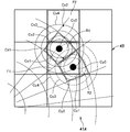
- FIG. 5, FIG. 6, and FIG. 7 are explanatory diagrams showing examples of likelihood calculation methods by the object detection device 3 according to the first embodiment.
- FIG. 5 shows an example of an area where the distance from the radar 2A is relatively close (that is, when the size of the processing cell F is relatively large with respect to the size of the radar cell R) with respect to one radar 2A.
- the likelihood regarding the measured values of the radar cells R1 and R2 is calculated according to the distance from the center points Cx0 and Cy0.
- the likelihood is set for the radar cell R1 according to the region between the plurality of concentric circles Cx1 to Cx4 surrounding the center point Cx0.
- Likelihood 0.6 in the annular region up to Cx2
- likelihood 0.4 in the annular region up to the circle Cx3 outside the circle Cx2
- likelihood in the annular region between the circle Cx4 outside the circle Cx3. 0.2.
- the likelihood outside the circle Cx4 can be zero.
- the likelihood can be set according to the region between the plurality of concentric circles Cy1 to Cy4 surrounding the center point Cy.
- the likelihood regarding the measurement value of each radar cell R can be calculated based on the distance between each radar cell R and each processing cell F.
- the distance between each radar cell R and each processing cell F can be easily calculated as the distance between the centers of those cells.
- the likelihood changes stepwise based on the distance from the center of the radar cell R (the distance between each radar cell R and each processing cell F).
- the likelihood may be linearly changed according to the distance between R and each processing cell F.
- the lattice value calculation unit 32 may, for example, calculate the sum of the likelihood at the center position Cz1 for the processing cell F1 (in the example of FIG. 5, up to the circle Cx2 outside the circle Cx1 where the center position Cz1 is located).
- the object detection system 1 can perform appropriate clustering on the measurement information of the radar 2 by calculating the lattice value based on the maximum likelihood value or the sum of the likelihoods.
- the lattice value calculation unit 32 is not limited to the maximum value of multiple likelihoods and the sum of the likelihoods, but may use other statistical values (for example, average values, intermediate values) regarding the multiple likelihoods.
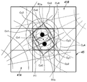
- FIG. 6 shows an example of an area where the distances from the radars 2A and 2B are relatively close, as in the case of FIG.
- the radar cell R1a of the radar grating 41A and the radar cell R1b of the radar grating 41B have predetermined measurement values (here, 1), and the surrounding radar cells have measurement values. (The measured value is 0).
- Likelihood for the measurement values of the radar cells R1a and R1b is calculated according to the distance from the center points Cx0 and Cy0, as in the case of FIG. That is, regarding the radar cell Ra1, the likelihood is set according to the region between the plurality of concentric circles Cx1 to Cx4 surrounding the center point Cx0, and regarding the radar cell R1b, the likelihood of the plurality of concentric circles Cy1 to Cy4 surrounding the center point Cy0 is set. Likelihood is set according to the area between.
- the lattice value calculation unit 32 Based on the likelihood set in such a manner, the lattice value calculation unit 32, for example, for the processing cell F1, the maximum likelihood value at the center position Cz1 (here, from the center point Cx0 where the center position Cz1 is located).
- Lattice values can be similarly set for other processing cells other than the processing cell F1.
- FIG. 7 shows an example of an area where the distance from the radar 2A is relatively far (that is, when the size of the processing cell F is relatively small with respect to the size of the radar cell R).
- the likelihood related to the measurement value of the radar cell R1 can be obtained in the same manner as in the example shown in FIG. 5 (or FIG. 6) regardless of the size difference between the radar grating 41 and the processing cell F. .
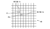
- FIG. 8 is an explanatory diagram showing an outline of neighborhood calculation based on an algorithm according to DBSCAN by the object detection device 3 according to the first embodiment.
- the neighborhood calculation between the processing cell F1 at the position “a” and the processing cell F2 at the position “b” shown in FIG. 8 can be executed based on the following equation (1).
- the neighborhood calculation can be similarly performed for cells other than the processing cells F1 and F2.
- a and b are the positions of the processing cells F1 and F2.
- Va and Vb are lattice values of the processing cells F1 and F2 calculated based on the above-described likelihood.
- G relating to Va and Vb relates to a difference between lattice values (distance between lattice values), and here follows the Gaussian distribution as described above.
- k is a coefficient determined as appropriate.
- the processing cell F as the clustering target point has minPts (preset value) adjacent points (processing cells) that satisfy the formula (1) in the algorithm according to the DBSCAN. If the processing cell as the clustering target point has a core point (processing cell) that satisfies the relationship of Expression (1), the core point is within the radius ⁇ . It is determined to be a point.
- a cluster is formed from the plurality of processing cells F determined to be core points, and further, the processing cell F determined to have a core point within the radius ⁇ is assigned to the cluster.
- the processing cells are clustered based on the lattice values considering the likelihood calculated based on the distance between each radar cell R and each processing cell F. Appropriate clustering can be performed on the measurement information.
- FIG. 9 is an explanatory diagram showing an information output result (result of clustering process) by the object detection device 3 according to the first embodiment.
- the object detection device 3 can display the result of the clustering process on the display screen 51 of the information output unit 24 as shown in FIG.
- FIG. an example in which two objects 52 and 53 are detected in the measurement areas 18A and 18B of the radars 2A and 2B is shown.
- On the radar 2A side (left side in FIG. 9) of the objects 52 and 53 there are mainly a plurality of measurement points 55 (indicated by crosses in FIG. 9) based on the measurement result of the radar 2A.
- a plurality of measurement points 56 (indicated by black circles in FIG. 9) based on the measurement results of the radar 2B mainly exist on the 53 radar 2B side (the right side in FIG. 9).
- areas here, polygonal areas formed by clustering the plurality of measurement points 55 and 56 are shown as detected objects 52 and 53, respectively.
- the object detection system 1 can perform clustering with high accuracy based on the measurement information of the plurality of radars 2A and 2B, and output the result (object detection result).
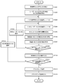
- FIG. 10 is a flowchart showing an operation procedure related to object detection processing by the object detection device 3 according to the first embodiment.
- the object detection device 3 extracts the coordinates of the center point of each processing cell and each radar cell from the setting information of the processing grid 45 and the radar grid 41 stored in advance in the storage unit 25. (ST101, ST102).
- the object detection device 3 determines whether or not selection of all the radar cells Ri has been completed (ST107), and when there is a radar cell Ri that has not been selected (ST107: No). The next radar cell Ri is selected (ST108), and step ST104 is executed again. The processes in steps ST104 to ST106 are repeatedly executed until selection of all radar cells Ri is completed. When measurement information of a plurality of radars 2 is used for the object detection process, radar cells Ri for all the radars 2 are selected.
- the object detection device 3 calculates the lattice value of the target processing cell Fj based on the likelihood calculated in step ST106 (ST109).
- the likelihood calculated in step ST106 can be set as the lattice value of the target processing cell Fj.
- the object detection device 3 determines whether or not selection of all the processing cells Fj is completed (ST110), and there is a processing cell Fj that has not been selected (ST110: No).
- the next processing cell Fj is selected (ST111), and step ST103 is executed again.
- the processes of steps ST103 to ST109 are repeatedly executed until selection of all radar cells Ri is completed.
- the object detection apparatus 3 performs a clustering process on the processing cells Fj (ST112).
- the object detection device 3 outputs the result of clustering processing (object detection result) in step ST112 to the display screen 51 (see FIG. 9) of the information output unit 24 (ST113).
- FIG. 11 is a flowchart showing an operation procedure regarding object detection processing by the object detection device 3 of the object detection system 1 according to the second embodiment
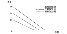
- FIG. 12 shows the selection of the likelihood calculation method in step ST206 in FIG. It is explanatory drawing which shows the outline
- matters not particularly mentioned below are the same as those of the object detection system 1 according to the first embodiment described above, and detailed description thereof is omitted.
- the object detection device 3 extracts the center point of each processing cell and each radar cell, respectively (ST201, ST202).
- step ST202 for each radar cell, an index value used for selection of a likelihood calculation method to be described later is acquired.
- an index value for example, the reflection intensity relating to each radar cell or the Doppler velocity can be used.
- steps ST203 to ST205 are the same processes as steps ST103 to ST105 shown in FIG. Thereafter, the object detection device 3 selects a likelihood calculation method based on the index value acquired in step ST202 (ST206).
- a likelihood calculation method can be selected using the reflection intensity as an index value.
- the distance (horizontal axis) calculated in step ST205 according to the magnitude of the reflection intensity (three levels of “strong”, “medium”, and “weak” set in advance) and in step ST207 described later.
- the relationship with the calculated likelihood (vertical axis) changes. That is, when the reflection intensity related to the radar cell to be processed is “strong”, the likelihood calculation method is selected that decreases with increasing distance with 1.0 as the maximum value for the likelihood calculated in step ST207.
- the reflection intensity is “medium” and “weak”, regarding the likelihood calculated in step ST207, there is a likelihood calculation method that decreases as the distance increases with 0.8 and 0.6 as maximum values, respectively. Each is selected.
- the relationship between the likelihood and the distance according to the index value is not limited to that shown in FIG. 12, and various changes can be made.
- a likelihood calculation method (relation between likelihood and distance) can be set according to the magnitude.
- step ST207 the object detection device 3 uses the likelihood calculation method selected in step ST206 (for example, a linear equation corresponding to the reflection intensity “strong” in FIG. 12) according to the distance. Calculate the likelihood.
- the object detection system 1 can appropriately calculate the likelihood related to the measurement value of the radar cell based on a predetermined index (reflection intensity, Doppler velocity, etc.).
- steps ST208 to ST214 are the same processes as steps ST107 to ST113 shown in FIG.
- FIG. 13 is a flowchart showing an operation procedure related to object detection processing by the object detection device 3 of the object detection system 1 according to the third embodiment
- FIG. 14 shows an outline of the lattice setting method in step ST301 in FIG. It is explanatory drawing shown.
- matters not specifically mentioned below are the same as those in the object detection system 1 according to the first or second embodiment described above, and detailed description thereof is omitted.
- a plurality of radars (here, radars 2A and 2B) are arranged side by side in the same direction, and similarly, radar gratings 41A and 41B ( The measurement area is also arranged in the same direction.
- the object detection device 3 increases the size of the plurality of processing cells F constituting the processing grid 45 based on the distance from the radars 2A and 2B as the distance from the radars 2A and 2B increases. (ST301).
- the orthogonal coordinates of the processing grid 45 are set based on the virtual straight line L connecting the positions of the two radars 2A and 2B, and the size of the processing cell F is equal to the virtual straight line L. It is set so as to increase as it moves away.
- the processing cell F has three different sizes in the areas 61 to 63 arranged in order from the virtual straight line L side.
- the present invention is not limited to this, and for example, a different size may be set for each column of the processing cells F arranged along the virtual straight line L.
- steps ST302 to ST314 are the same as steps ST101 to ST113 shown in FIG.
- the radar radars 41A and 41B for measurement and the processing grid 45 for clustering processing are associated with the plurality of radars 2A and 2B arranged in the same direction. Can be set appropriately.
- An object detection device, an object detection system, and an object detection method according to the present disclosure enable appropriate clustering with respect to radar measurement information, and detect an object based on radar measurement information. It is useful as a system and an object detection method.
- Object detection system 2 Radar 2A: Radar 2B: Radar 3: Object detection device 11: Vehicle 12: Pedestrian 15: Intersection 16A, 16B: Roadside devices 18A, 18B: Measurement area 21: Communication unit 22: Input unit 23 : Control unit 24: Information output unit 25: Storage unit 31: Grid setting unit 32: Grid value calculation unit 33: Cluster generation unit 41: Radar grid 45: Processing grid 51: Display screen 52, 53: Objects 55, 56: Measurement point
Landscapes
- Engineering & Computer Science (AREA)
- Radar, Positioning & Navigation (AREA)
- Remote Sensing (AREA)
- Physics & Mathematics (AREA)
- General Physics & Mathematics (AREA)
- Computer Networks & Wireless Communication (AREA)
- Electromagnetism (AREA)
- Chemical & Material Sciences (AREA)
- Analytical Chemistry (AREA)
- Radar Systems Or Details Thereof (AREA)
- Traffic Control Systems (AREA)
Abstract
【課題】レーダーの測定情報に関して適切なクラスタリングを行う。 【解決手段】物体検出装置3のプロセッサ23が、レーダー2の測定エリア18にそれぞれ対応して設定され、かつ複数のレーダーセルRから構成される測定用のレーダー格子41の設定情報を取得し、測定エリア18に対応して設定され、かつ複数の処理用セルFから構成されたクラスタリング処理用の処理用格子45の設定情報を取得し、各レーダーセルRと各処理用セルFとの距離に基づき、各レーダーセルRの測定値に関する尤度をそれぞれ算出し、その尤度に基づき、処理用格子45における各処理用セルFの格子値をそれぞれ算出し、各処理用セルFについて、当該各処理用セルFの間の距離または格子値、あるいは前記距離と前記格子値の両方に基づきクラスタリングを行う構成とする。
Description
本開示は、レーダーの測定情報に基づいて物体を検出する物体検出装置、物体検出システム、及び物体検出方法に関する。
従来、交通事故防止等を目的として、道路などに設置されたセンサによって車両や歩行者等の物体を検出する技術が開発されており、そのようなセンサとして、カメラ等に比べて天候等の影響を受けにくく、物体までの距離や、角度、速度などを計測できるレーダーが知られている。レーダーによる測定では、1つの検出対象に対して複数の測定点(反射点)が取得されるため、それらの測定点を検出対象に対応づけるためのクラスタリングが実施される。
上記のようなクラスタリングの手法としては、例えば、クラスタリングアルゴリズムとしてDBSCAN (Density-Based Spatial Clustering of Applications with Noise)を用いる方法が普及している(非特許文献1参照)。
また、単一または複数のレーダーにより取得された測定点についてクラスタリングを実施する技術として、例えば、複数の測定点の各相対速度ベクトルに基づいて各測定点を含む仮想物体の合成相対速度ベクトルを算出し、その算出された複数の仮想物体の合成相対速度ベクトルが等しい仮想物体を実物体としてグループ化するレーダー信号処理装置が知られている(特許文献1参照)。
D. Kellner, J. Klappstein and K. Dietmayer, "レーダーデータの拡張オブジェクトをクラスタリングするためのグリッドベースDBSCAN(Grid-based DBSCAN for clustering extended objects in radar data)," Intelligent Vehicles Symposium 2012, pp.365-370.
ところで、上記DBSCANによるクラスタリングでは、互いに重なる測定エリアが設定された(すなわち、同一物体を測定可能な)複数のレーダーによる測定点が処理対象に含まれる場合には、測定エリアの同一位置におけるそれらレーダーの空間分解能が異なると、パラメータ(ε、minPts)を適切に設定することが難しい。
また、上記特許文献1に記載された従来技術によれば、例えば、複数のレーダーが車両の前方の左右2箇所に配置され、仮想物体の同一位置に対する複数のレーダーの検出結果(左右の相対速度ベクトル成分)を取得することにより、仮想物体の合成相対速度ベクトルが求められる。しかしながら、例えば、交差点に対向配置された2つのレーダーが、互いに異なる方向(例えば、前方および後方)から同一物体を検出するような構成では、各レーダーが、その物体の一方側(例えば、前部)および他方側(例えば、後部)をそれぞれ検出することになるため、各レーダーで検出対象の同一位置に関する測定点を取得することは困難である。
本開示は、このような従来技術の課題を鑑みて案出されたものであり、レーダーの測定情報に関して適切なクラスタリングを行うことを可能とする物体検出装置、物体検出システム、及び物体検出方法を提供することを主目的とする。
本開示の物体検出装置は、1以上のレーダーの測定情報に基づいて物体を検出するための処理を実行するプロセッサを備えた物体検出装置であって、前記プロセッサは、前記各レーダーの測定エリアにそれぞれ対応して設定され、かつ複数のレーダーセルから構成される測定用のレーダー格子の設定情報を取得し、前記測定エリアに対応して設定され、かつ複数の処理用セルから構成されるクラスタリング処理用の処理用格子の設定情報を取得し、前記各レーダーセルと前記各処理用セルとの距離に基づき、前記各レーダーセルの測定値に関する尤度をそれぞれ算出し、前記尤度に基づき、前記処理用格子における前記各処理用セルの格子値をそれぞれ算出し、前記各処理用セルについて、当該各処理用セルの間の距離または前記格子値、あるいは前記距離と前記格子値の両方に基づきクラスタリングを行う構成とする。
また、本開示の物体検出システムは、前記物体検出装置と、前記1以上のレーダーとを備える構成とする。
また、本開示の物体検出方法は、1以上のレーダーの測定情報に基づいて物体を検出するための処理を実行する物体検出装置による物体検出方法であって、前記各レーダーの測定エリアにそれぞれ対応して設定され、かつ複数のレーダーセルから構成される測定用のレーダー格子の設定情報を取得し、前記測定エリアに対応して設定され、かつ複数の処理用セルから構成されるクラスタリング処理用の処理用格子の設定情報を取得し、前記各レーダーセルと前記各処理用セルとの距離に基づき、前記各レーダーセルの測定値に関する尤度をそれぞれ算出し、前記尤度に基づき、前記処理用格子における前記各処理用セルの格子値をそれぞれ算出し、前記各処理用セルについて、当該各処理用セルの間の距離あるいは前記格子値、あるいは前記距離と前記格子値の両方に基づきクラスタリングを行う構成とする。
本開示によれば、レーダーの検出結果に関して適切なクラスタリングを行うことにより、検出対象を容易に検出することが可能となる。
前記課題を解決するためになされた第1の発明は、1以上のレーダーの測定情報に基づいて物体を検出するための処理を実行するプロセッサを備えた物体検出装置であって、前記プロセッサは、前記各レーダーの測定エリアにそれぞれ対応して設定され、かつ複数のレーダーセルから構成される測定用のレーダー格子の設定情報を取得し、前記測定エリアに対応して設定され、かつ複数の処理用セルから構成されるクラスタリング処理用の処理用格子の設定情報を取得し、前記各レーダーセルと前記各処理用セルとの距離に基づき、前記各レーダーセルの測定値に関する尤度をそれぞれ算出し、前記尤度に基づき、前記処理用格子における前記各処理用セルの格子値をそれぞれ算出し、前記各処理用セルについて、当該各処理用セルの間の距離または前記格子値、あるいは前記距離と前記格子値の両方に基づきクラスタリングを行う構成とする。
これによると、各レーダーセルと各処理用セルとの距離に基づき算出された尤度を考慮した格子値に基づき処理用セルのクラスタリングを行うため、レーダーの測定情報に関して適切なクラスタリングを行うことが可能となる。
また、第2の発明は、前記プロセッサは、前記各レーダーセルと1つの前記処理用格子との距離に基づき、前記尤度が複数算出された場合、それら複数の尤度における最大値を当該処理用格子の格子値として算出する構成とする。
これによると、単一または複数のレーダーの測定情報を利用して同一物体を検出する場合に、レーダーの測定情報に関して適切なクラスタリングを行うことが可能となる。
また、第3の発明は、前記プロセッサは、前記各レーダーセルと1つの前記処理用格子との距離に基づいて、前記尤度が複数算出された場合、それら複数の尤度の和を当該処理用格子の格子値として算出する構成とする。
これによると、単一または複数のレーダーの測定情報を利用して同一物体を検出する場合に、レーダーの測定情報に関して適切なクラスタリングを行うことが可能となる。
また、第4の発明は、前記プロセッサは、前記各レーダーセルに関する反射強度に基づき、前記各レーダーセルの測定値に関する尤度をそれぞれ算出する構成とする。
これによると、各レーダーセルの測定値に関する尤度を、反射強度に基づき適切に算出することが可能となる。
また、第5の発明は、前記プロセッサは、前記各レーダーセルに関するドップラー速度に基づき、前記各レーダーセルの測定値に関する尤度をそれぞれ算出する構成とする。
これによると、各レーダーセルの測定値に関する尤度を、ドップラー速度に基づき適切に算出することが可能となる。
また、第6の発明は、前記プロセッサは、処理対象となる一対の前記処理用格子における前記格子値の差分に基づき前記クラスタリングを行う構成とする。
これによると、各処理用セルの間の距離およびそれらの格子値の差分に基づき、適切なクラスタリングを行うことが可能となる。
また、第7の発明は、前記各レーダーセルと前記各処理用セルとの距離は、それらのセルの中心間の距離である構成とする。
これによると、各レーダーセルと各処理用セルとの距離を簡易かつ適切に算出することが可能となる。
また、第8の発明は、前記レーダー格子は、極座標に基づいて構成され、前記処理用格子は、直交座標に基づいて構成される構成とする。
これによると、測定用のレーダー格子およびクラスタリング処理用の処理用格子を適切に設定することが可能となる。
また、第9の発明は、上記第1から第8の発明のいずれかに係る物体検出装置と、前記1以上のレーダーとを備えた物体検出システムである。
これによると、各レーダーセルと各処理用セルとの距離に基づき算出された尤度を考慮した格子値に基づき処理用セルのクラスタリングを行うため、レーダーの測定情報に関して適切なクラスタリングを行うことが可能となる。
また、第10の発明は、前記1以上のレーダーは、道路に設置された構成とする。
これによると、道路を通過する車両や人などを精度良く検出することができ、その結果、交通状況を精度良く把握することが可能となる。
また、第11の発明は、前記1以上のレーダーは、同一方向に向けて並べて配置された複数のレーダーからなり、前記処理用格子を構成する前記複数の処理用セルのサイズが、前記測定エリアにおける前記レーダーから離れるにつれて大きくなるように設定された構成とする。
これによると、同一方向に向けて並べて配置された複数のレーダーに関し、測定用のレーダー格子およびクラスタリング処理用の処理用格子を適切に設定することが可能となる。
また、第12の発明は、1以上のレーダーの測定情報に基づいて物体を検出するための処理を実行する物体検出装置による物体検出方法であって、前記各レーダーの測定エリアにそれぞれ対応して設定され、かつ複数のレーダーセルから構成される測定用のレーダー格子の設定情報を取得し、前記測定エリアに対応して設定され、かつ複数の処理用セルから構成されるクラスタリング処理用の処理用格子の設定情報を取得し、前記各レーダーセルと前記各処理用セルとの距離に基づき、前記各レーダーセルの測定値に関する尤度をそれぞれ算出し、前記尤度に基づき、前記処理用格子における前記各処理用セルの格子値をそれぞれ算出し、前記各処理用セルについて、当該各処理用セルの間の距離または前記格子値、あるいは前記距離と前記格子値の両方に基づきクラスタリングを行う構成とする。
これによると、各レーダーセルと各処理用セルとの距離に基づき算出された尤度を考慮した格子値に基づき処理用セルのクラスタリングを行うため、レーダーの測定情報に関して適切なクラスタリングを行うことが可能となる。
以下、本開示の実施の形態を、図面を参照しながら説明する。なお、本開示において、図中に示された物体検出システム1の各構成要素を示す符号に関し、同一の数字の後に付されたアルファベット(例えば、レーダー2A、2BにおけるA、B)は、同等の構成要素を区別して説明するために用いられ、特に区別を必要としない場合には数字のみを用いて総称する(例えば、レーダー2と示す。)。
(第1実施形態)
図1は、第1実施形態に係る物体検出システム1の全体構成図である。
図1は、第1実施形態に係る物体検出システム1の全体構成図である。
物体検出システム1は、複数のレーダー2A、2Bと、それらレーダー2A、2Bから取得した測定情報に基づいて検出対象となる物体を検出するための処理(以下、「物体検出処理」という。)を実行する物体検出装置3と、を主として備える。
レーダー2は、電波を放射してその反射波を検出することにより、自装置の周辺に存在する物体を検知して、その物体までの距離や、角度、速度などを測定することが可能である。レーダー2は、例えば79GHz帯ミリ波レーダーから構成されるが、これに限らず、他の方式のレーダー(例えば、レーザーレーダー等)をレーダー2として用いてもよい。なお、物体検出システム1は、複数のレーダー2から取得した測定情報を利用するのに好適であるが、単一のレーダー2を備えた構成としてもよい。
物体検出装置3は、公知のハードウェアを有するコンピュータなどから構成される情報処理装置である。物体検出装置3は、公知の通信用ケーブルや、通信ネットワークを介してレーダー2に接続され、レーダー2から出力された測定情報を取得することが可能である。測定情報には、レーダー2の測定エリア内の各位置(測定点)における測定値(例えば、0、1の2値)が含まれる。
図2は、第1実施形態に係る物体検出システム1の適用例を示す説明図である。
物体検出システム1は、例えば図2に示すように、十字道路10に設置されたレーダー2A、2Bから取得した測定情報に基づいて、道路10を通行する車両11や歩行者12などの移動体(検出対象)を検出することが可能である。
レーダー2A、2Bは、例えば、交差点15の対角の位置に(すなわち、互いに対向するように)配置される。ここでは、レーダー2A、2Bは、車載器と通信可能な公知の路側機16A、16Bにそれぞれ設置される。レーダー2A、2Bは、それぞれ交差点15の中央に向けられた略扇形の測定エリア18A、18Bを有する。測定エリア18A、18Bは、少なくとも一部が互いに重なるように設定され(図2中の濃い色で塗られた部分を参照。)、これにより同一位置における移動体を同時に検知することが可能である。
また、物体検出装置3は、路側機16Aに設置される。物体検出装置3は、レーダー2A、2Bから取得した測定情報に基づいて移動体を検出するが、一方のレーダー(例えば、レーダー2A)のみから移動体を検出することも可能である。物体検出装置3は、レーダー2と一体に設けられてもよく、また、物体検出装置3を遠隔の監視施設や、交通管制センターなどに設置することも可能である。
なお、物体検出システム1は、道路を通行する移動体の検出に限らず、他の任意の施設や、交通機関等における移動体等の検出を行うことが可能である。
図3は、第1実施形態に係る物体検出装置3の概略構成を示すブロック図であり、図4は、レーダー2の測定エリアに対して設定される格子(測定用のレーダー格子41A、41Bおよびクラスタリング処理用の処理用格子45)の一例を示す説明図である。
物体検出装置3において、通信部21は、レーダー2から測定情報を取得するための通信インタフェースを有する。また、入力部22は、キーボードやマウスなどの公知の入力装置を有し、物体検出装置3のユーザ(オペレータ)による各種情報の入力や、物体検出処理に関する設定操作を可能とする。
制御部23は、プロセッサを有し、物体検出処理や、レーダー2からの測定情報の取得等の処理を実行する。詳細は後述するが、制御部23において、格子設定部31は、レーダー2A、2Bの測定エリア18A、18Bにそれぞれ対応して設定される測定用の格子(以下、「レーダー格子」という。)の設定情報を取得または生成する。レーダー格子の設定情報には、レーダー格子における位置情報等(測定点の位置情報等)が含まれる。また、格子設定部31は、測定エリアに対応して設定されるクラスタリング処理用の格子(以下、「処理用格子」という。)の設定情報を取得または生成する。処理用格子の設定情報には、処理用格子における位置情報等(測定点に対応付けられるクラスタリング対象点の位置情報等)が含まれる。
ここで、図4に示すように、レーダー2A、2Bのレーダー格子41A、41Bは、それぞれ極座標に基づき設定され、測定エリア18A、18Bにそれぞれ対応する略扇形をなす。レーダー格子41A、41Bは、それぞれレーダー2A、2Bを中心として、所定の角度で放射状に伸びる複数の直線と、それぞれ異なる半径で配置された複数の円弧とから構成され、それら直線および円弧により画定される複数のセルRa、Rb(以下、「レーダーセル」という。)をそれぞれ含む。
また、処理用格子45は、直交座標に基づき設定され、それぞれ所定の間隔をおいて縦方向に延びる複数の縦線と、それぞれ所定の間隔をおいて横方向に延びる複数の横線とから構成され、それら縦線および横線によって画定される複数のセル(以下、「処理用セル」という。)Fを含む。なお、処理用格子45は、後述するDBSCANのアルゴリズムを利用した処理のために設定される格子である。
なお、各レーダーセルRのサイズ(略矩形の縦横の長さ)は、例えば、数cmから10cm程度の範囲で設定することができる。また、長方形または正方形の処理用セルFのサイズは、例えば、10cmから50cm程度の範囲で設定することができる。ただし、レーダー格子41および処理用格子45の構成(セルのサイズ、形状を含む)については適宜変更することが可能である。
再び図3を参照して、制御部23における格子値算出部32は、レーダー2の測定情報に基づき、クラスタリング処理に用いられる各処理用セルFの値(以下、「格子値」という。)を算出する。後に詳述するように、そのような格子値は、レーダー2の測定情報(各レーダーセルRにおける測定値に関する尤度)から算出される。また、クラスタ生成部33は、各処理用セルF(クラスタリング対象点)についてクラスタリング処理を行う。
クラスタ生成部33によるクラスタリング処理は、公知のDBSCAN (Density-Based Spatial Clustering of Applications with Noise)のアルゴリズムにしたがって実施される。ただし、本開示のクラスタリング処理では、近傍計算を行う際に、各処理用セルFの間の距離のみならず、上述の格子値算出部32によって算出された各処理用セルFの格子値を用いる。また、DBSCANによる近傍計算では、半径ε(Eps-neighborhood of that point)以内に少なくともminPts(minimum number of points)個の隣接点を持つコア点(処理用セルF)と、半径ε以内にコア点を持つ点(処理用セルF)とが判定(抽出)される。
上述の格子設定部31、格子値算出部32、及びクラスタ生成部33による処理は、プロセッサが所定のプログラムを実行することによりそれぞれ実現可能である。
情報出力部24は、液晶ディスプレイなどの公知のディスプレイ装置を有し、物体検出処理に関連する各種情報や、その処理結果を表示する。
記憶部25は、公知の記憶装置を有し、プロセッサによって実行されるプログラムや、物体検出処理に関連する各種情報や、その処理結果を記憶することが可能である。
図5、図6、及び図7は、それぞれ第1実施形態に係る物体検出装置3による尤度算出方法の一例を示す説明図である。
図5では、1つのレーダー2Aに関し、当該レーダー2Aからの距離が比較的近いエリアの例(すなわち、レーダーセルRのサイズに対して処理用セルFのサイズが比較的大きい場合)を示している。ここでは、レーダー格子41AのレーダーセルR1、R2が所定の測定値(=1)を有し、それらの周辺のレーダーセルは測定値を有しない(測定値=0である)ものとする。
レーダーセルR1、R2の測定値に関する尤度は、それらの中心点Cx0、Cy0からの距離に応じて算出される。図5の例では、レーダーセルR1に関し、その中心点Cx0を囲む複数の同心円Cx1~Cx4の間の領域に応じて尤度が設定される。
例えば、中心点Cx0における尤度を測定値と同じ値(すなわち、尤度=1)として、中心点Cx0から円Cx1までの間の領域では尤度=0.8とし、円Cx1の外側における円Cx2までの環状領域では尤度=0.6とし、円Cx2の外側における円Cx3までの環状領域では尤度=0.4とし、円Cx3の外側における円Cx4までの間の環状領域では尤度=0.2とすることができる。なお、円Cx4の外側における尤度は0とすることができる。また、レーダーセルR2に関しても同様に、中心点Cyを囲む複数の同心円Cy1~Cy4の間の領域に応じて尤度を設定することができる。
そのように設定された尤度に基づき、格子値算出部32は、処理用セルF1について、その中心位置Cz1における尤度の最大値(ここでは、中心位置Cz1が位置する円Cx1の外側における円Cx2までの環状領域における尤度=0.6と、円Cy2の外側における円Cy3までの環状領域では尤度=0.4との最大値となる0.6)を格子値として算出することができる。また、格子値算出部32は、処理用セルF2について、その中心位置Cz2における尤度の最大値(ここでは、中心位置Cz2が位置する円Cx3の外側における円Cx4までの間の環状領域では尤度=0.2)を格子値として算出することができる。処理用セルF1、F2以外の他の処理用セルについても同様に格子値を設定することができる。
このように、各レーダーセルRの測定値に関する尤度については、各レーダーセルRと、各処理用セルFとの距離に基づき算出することが可能である。各レーダーセルRと各処理用セルFとの距離は、それらのセルの中心間の距離として容易に算出することができる。図5の例では、レーダーセルRの中心からの距離(各レーダーセルRと各処理用セルFとの距離)に基づき、尤度が段階的に変化するが、これに限らず、各レーダーセルRと各処理用セルFとの距離に応じて尤度を線形に変化させてもよい。
また別法として、格子値算出部32は、例えば、処理用セルF1について、当該セル内に設定された尤度の最大値(図5の例では、処理用セルF1内に位置する中心点Cx0、Cy0における尤度=1)を格子値として算出してもよい(他の処理用セルについても同様)。
また別法として、格子値算出部32は、例えば、処理用セルF1について、その中心位置Cz1における尤度の和(図5の例では、中心位置Cz1が位置する円Cx1の外側における円Cx2までの環状領域における尤度=0.6と、円Cy2の外側における円Cy3までの環状領域では尤度=0.4との和となる1.0)を格子値として算出してもよい(他の処理用セルについても同様)。
このように、物体検出システム1では、尤度の最大値や尤度の和に基づき格子値を算出することにより、レーダー2の測定情報に関して適切なクラスタリングを行うことが可能となる。なお、格子値算出部32は、複数の尤度の最大値および尤度の和に限らず、複数の尤度に関する他の統計値(例えば、平均値、中間値)を用いることもできる。
図6では、図5の場合と同様に、レーダー2A、2Bからの距離が比較的近いエリアの例を示している。ここでは、2つのレーダー2A、2Bに関し、レーダー格子41AのレーダーセルR1aおよびレーダー格子41BのレーダーセルR1bが所定の測定値(ここでは、1)を有し、それらの周辺のレーダーセルが測定値を有しない(測定値が0である)ものとする。
レーダーセルR1a、R1bの測定値に関する尤度は、図5の場合と同様に、それらの中心点Cx0、Cy0からの距離に応じて算出される。つまり、レーダーセルRa1に関し、中心点Cx0を囲む複数の同心円Cx1~Cx4の間の領域に応じて尤度が設定され、また、レーダーセルR1bに関し、中心点Cy0を囲む複数の同心円Cy1~Cy4の間の領域に応じて尤度が設定される。
そのように設定された尤度に基づき、格子値算出部32は、例えば、処理用セルF1について、その中心位置Cz1における尤度の最大値(ここでは、中心位置Cz1が位置する中心点Cx0から円Cx1までの間の領域における尤度=0.8と、中心点Cy0から円Cy1までの間の領域における尤度=0.8との最大値となる0.8)を格子値として算出することができる。処理用セルF1以外の他の処理用セルについても同様に格子値を設定することができる。
なお、図6の例においても、図5について説明した他の尤度算出方法(尤度の和に基づく方法等)を適用することが可能である。
図7では、レーダー2Aからの距離が比較的遠いエリアの例(すなわち、レーダーセルRのサイズに対して処理用セルFのサイズが比較的小さい場合)を示している。レーダーセルR1の測定値に関する尤度については、そのようなレーダー格子41と処理用セルFとのサイズの違いに拘わらず、図5(または図6)に示した例と同様に求めることができる。
格子値算出部32は、例えば、処理用セルF1について、その中心位置Cz1における尤度の最大値(ここでは、中心位置Cz1が位置する中心点Cy0における尤度=1.0)を格子値として算出することができる。処理用セルF1以外の他の処理用セルについても同様に格子値を設定することができる。
図8は、第1実施形態に係る物体検出装置3によるDBSCANに準じたアルゴリズムに基づく近傍計算の概要を示す説明図である。
物体検出装置3では、例えば、図8に示す位置aにおける処理用セルF1と、位置bにおける処理用セルF2との近傍計算を以下の式(1)に基づき実行することができる。なお、処理用セルF1、F2以外の他のセルについても同様に近傍計算を行うことができる。

ここで、aおよびbは、処理用セルF1、F2の位置である。また、VaおよびVbは、それぞれ上述の尤度に基づき算出された処理用セルF1、F2の格子値である。また、VaおよびVbに関するGは、格子値の差分(格子値間の距離)に関するものであり、ここでは上記のとおりガウシアン分布に従う。なお、kは適宜定められる係数である。
このような近傍計算により、クラスタリング対象点としての処理用セルFは、DBSCANに準じたアルゴリズムにおいて、式(1)を満たすminPts個(予め設定された値)の隣接点(処理用セル)を持つ場合にコア点であると判定され、また、クラスタリング対象点としての処理用セルが、式(1)の関係を満たすコア点(処理用セル)を有する場合に、半径ε以内にコア点を持つ点であると判定される。
その結果、コア点であると判定された複数の処理用セルFからクラスタが構成され、さらに、半径ε以内にコア点を持つ点と判定された処理用セルFが当該クラスタに割り当てられる。
このように、物体検出システム1では、各レーダーセルRと、各処理用セルFとの距離に基づき算出された尤度を考慮した格子値に基づき処理用セルのクラスタリングを行うため、レーダー2の測定情報に関して適切なクラスタリングを行うことが可能となる。
図9は、第1実施形態に係る物体検出装置3による情報出力結果(クラスタリング処理の結果)を示す説明図である。
物体検出装置3は、図9に示すように、情報出力部24のディスプレイ画面51にクラスタリング処理の結果を表示することが可能である。ここでは、レーダー2A、2Bの測定エリア18A、18Bに2つの物体52、53が検出された例が示されている。物体52、53のレーダー2A側(図9中の左側)には、レーダー2Aの測定結果に基づく複数の測定点55(図9中に×印で示す)が主として存在し、また、物体52、53のレーダー2B側(図9中の右側)には、レーダー2Bの測定結果に基づく複数の測定点56(図9中に黒丸印で示す)が主として存在する。また、ディスプレイ画面51には、それら複数の測定点55、56のクラスタリングによって形成された領域(ここでは、多角形形状の領域)が検出された物体52、53としてそれぞれ示されている。
このように、物体検出システム1では、複数のレーダー2A、2Bの測定情報に基づいて、精度良くクラスタリングを行い、その結果(物体の検出結果)を出力することが可能である。
図10は、第1実施形態に係る物体検出装置3による物体検出処理に関する動作手順を示すフロー図である。
物体検出処理において、まず、物体検出装置3は、記憶部25に予め記憶された処理用格子45およびレーダー格子41の設定情報から、それぞれ各処理用セルおよび各レーダーセルの中心点の座標を抽出する(ST101、ST102)。
続いて、物体検出装置3は、処理用セルFj(j=1~N)の1つを選択し(ST103)、さらに、レーダーセルRi(i=1~M)の1つを選択する(ST104)。そして、物体検出装置3は、それらの選択した処理用セルFjおよびレーダーセルRiの距離を算出し(ST105)、その算出した距離に応じた尤度を算出する(ST106)。
その後、物体検出装置3は、全てのレーダーセルRiの選択が完了したか否かを判定し(ST107)、そこで、選択が完了していないレーダーセルRiが存在する場合(ST107:No)には、次のレーダーセルRiを選択し(ST108)、再びステップST104を実行する。上記ステップST104~ST106の処理は、全てのレーダーセルRiの選択が完了するまで繰り返し実行される。なお、複数のレーダー2の測定情報が物体検出処理に用いられる場合には、それら全てのレーダー2に関するレーダーセルRiが選択される。
最終的に全てのレーダーセルRiの選択が完了すると(ST107:Yes)、物体検出装置3は、ステップST106において算出された尤度に基づき、対象の処理用セルFjの格子値を算出する(ST109)。ここでは、ステップST106で算出された尤度を対象の処理用セルFjの格子値として設定することができる。
その後、物体検出装置3は、全ての処理用セルFjの選択が完了したか否かを判定し(ST110)、そこで、選択が完了していない処理用セルFjが存在する場合(ST110:No)には、次の処理用セルFjを選択し(ST111)、再びステップST103を実行する。上記ステップST103~ST109の処理は、全てのレーダーセルRiの選択が完了するまで繰り返し実行される。
最終的に全ての処理用セルFjの選択が完了すると(ST110:Yes)、物体検出装置3は、処理用セルFjについて、クラスタリング処理を実行する(ST112)。
その後、物体検出装置3は、ステップST112のクラスタリング処理の結果(物体の検出結果)を、情報出力部24のディスプレイ画面51(図9参照)に出力する(ST113)。
(第2実施形態)
図11は、第2実施形態に係る物体検出システム1の物体検出装置3による物体検出処理に関する動作手順を示すフロー図であり、図12は、図11中のステップST206における尤度算出方式の選択手順の概要を示す説明図である。第2実施形態に係る物体検出システム1に関し、以下で特に言及しない事項については、上述の第1実施形態に係る物体検出システム1と同様として詳細な説明を省略する。
図11は、第2実施形態に係る物体検出システム1の物体検出装置3による物体検出処理に関する動作手順を示すフロー図であり、図12は、図11中のステップST206における尤度算出方式の選択手順の概要を示す説明図である。第2実施形態に係る物体検出システム1に関し、以下で特に言及しない事項については、上述の第1実施形態に係る物体検出システム1と同様として詳細な説明を省略する。
第2実施形態に係る物体検出処理において、まず、図10に示したステップST101、ST102と同様に、物体検出装置3は、各処理用セルおよび各レーダーセルの中心点をそれぞれ抽出する(ST201、ST202)。ただし、ステップST202では、各レーダーセルについて、後述する尤度の算出方式の選択に用いられる指標値を取得する。そのような指標値としては、例えば、各レーダーセルに関する反射強度や、ドップラー速度を用いることができる。
続くステップST203~ST205は、図10に示したステップST103~ST105とそれぞれ同様の処理である。その後、物体検出装置3は、ステップST202で取得した指標値に基づき、尤度の算出方式を選択する(ST206)。
ステップST206では、例えば図12に示すように、反射強度を指標値として尤度の算出方式を選択することができる。ここでは、反射強度の大きさ(予め設定された「強」、「中」、「弱」の3段階)に応じて、ステップST205で算出された距離(横軸)と、後述するステップST207で算出される尤度(縦軸)との関係(すなわち、尤度の算出方式)が変化する。つまり、処理対象のレーダーセルに関する反射強度が「強」である場合、ステップST207で算出される尤度に関し、1.0を最大値として距離の増大とともに減少する尤度算出方式が選択される。同様に、反射強度が「中」および「弱」である場合、ステップST207で算出される尤度に関し、それぞれ0.8および0.6を最大値として距離の増大とともに減少する尤度算出方式がそれぞれ選択される。
なお、指標値に応じた尤度と距離との関係は、図12に示すものに限らず、種々の変更が可能である。同様に、指標値としてドップラー速度を用いた場合にも、その大きさに応じて尤度の算出方式(尤度と距離との関係)を設定することが可能である。
その後、ステップST207では、物体検出装置3は、上記ステップST206で選択した尤度の算出方式(例えば、図12中の反射強度「強」に対応する直線の式)を用いて、距離に応じた尤度を算出する。
このように、物体検出システム1では、レーダーセルの測定値に関する尤度を、所定の指標(反射強度、ドップラー速度など)に基づき適切に算出することが可能となる。
続くステップST208~ST214は、図10に示したステップST107~ST113とそれぞれ同様の処理である。
(第3実施形態)
図13は、第3実施形態に係る物体検出システム1の物体検出装置3による物体検出処理に関する動作手順を示すフロー図であり、図14は、図13中のステップST301における格子設定方法の概要を示す説明図である。第3実施形態に係る物体検出システム1に関し、以下で特に言及しない事項については、上述の第1または第2実施形態に係る物体検出システム1と同様として詳細な説明を省略する。
図13は、第3実施形態に係る物体検出システム1の物体検出装置3による物体検出処理に関する動作手順を示すフロー図であり、図14は、図13中のステップST301における格子設定方法の概要を示す説明図である。第3実施形態に係る物体検出システム1に関し、以下で特に言及しない事項については、上述の第1または第2実施形態に係る物体検出システム1と同様として詳細な説明を省略する。
第3実施形態に係る物体検出システム1では、図14に示すように、複数のレーダー(ここでは、レーダー2A、2B)が同一方向に向けて並べて配置され、同様に、レーダー格子41A、41B(測定エリア)も同一方向に向けて配置される。
物体検出処理においては、まず、物体検出装置3は、レーダー2A、2Bからの距離に基づき、処理用格子45を構成する複数の処理用セルFのサイズを、レーダー2A、2Bから離れるにつれて大きくなるように設定する(ST301)。
より詳細には、図14に示すように、2つのレーダー2A、2Bの位置を結ぶ仮想直線Lに基づき、処理用格子45の直交座標が設定され、処理用セルFのサイズが、仮想直線Lから離れるにつれて大きくなるように設定される。ここでは、処理用セルFが、仮想直線L側から順に配置されたエリア61~63において異なる3つのサイズを有する例を示している。ただし、これに限らず、例えば、仮想直線Lに沿って配置された処理用セルFの1列ごとに異なるサイズが設定されてもよい。
なお、ステップST302~ST314は、図10に示したステップST101~ST113とそれぞれ同様の処理である。
このように、第3実施形態に係る物体検出システム1では、同一方向に向けて並べて配置された複数のレーダー2A、2Bに関し、測定用のレーダー格子41A、41Bおよびクラスタリング処理用の処理用格子45を適切に設定することが可能となる。
以上、本開示を特定の実施の形態に基づいて説明したが、これらの実施の形態はあくまでも例示であって、本開示はこれらの実施の形態によって限定されるものではない。なお、上記実施の形態に示した本開示に係る物体検出装置、物体検出システム、及び物体検出方法の各構成要素は、必ずしも全てが必須ではなく、少なくとも本開示の範囲を逸脱しない限りにおいて適宜取捨選択することが可能である。
本開示に係る物体検出装置、物体検出システム、及び物体検出方法は、レーダーの測定情報に関して適切なクラスタリングを行うことを可能とし、レーダーの測定情報に基づいて物体を検出する物体検出装置、物体検出システム、及び物体検出方法などとして有用である。
1 :物体検出システム
2 :レーダー
2A :レーダー
2B :レーダー
3 :物体検出装置
11 :車両
12 :歩行者
15 :交差点
16A、16B:路側機
18A、18B:測定エリア
21 :通信部
22 :入力部
23 :制御部
24 :情報出力部
25 :記憶部
31 :格子設定部
32 :格子値算出部
33 :クラスタ生成部
41 :レーダー格子
45 :処理用格子
51 :ディスプレイ画面
52、53:物体
55、56:測定点
2 :レーダー
2A :レーダー
2B :レーダー
3 :物体検出装置
11 :車両
12 :歩行者
15 :交差点
16A、16B:路側機
18A、18B:測定エリア
21 :通信部
22 :入力部
23 :制御部
24 :情報出力部
25 :記憶部
31 :格子設定部
32 :格子値算出部
33 :クラスタ生成部
41 :レーダー格子
45 :処理用格子
51 :ディスプレイ画面
52、53:物体
55、56:測定点
Claims (12)
- 1以上のレーダーの測定情報に基づいて物体を検出するための処理を実行するプロセッサを備えた物体検出装置であって、
前記プロセッサは、
前記各レーダーの測定エリアにそれぞれ対応して設定され、かつ複数のレーダーセルから構成される測定用のレーダー格子の設定情報を取得し、
前記測定エリアに対応して設定され、かつ複数の処理用セルから構成されるクラスタリング処理用の処理用格子の設定情報を取得し、
前記各レーダーセルと前記各処理用セルとの距離に基づき、前記各レーダーセルの測定値に関する尤度をそれぞれ算出し、
前記尤度に基づき、前記処理用格子における前記各処理用セルの格子値をそれぞれ算出し、
前記各処理用セルについて、当該各処理用セルの間の距離または前記格子値、あるいは前記距離と前記格子値の両方に基づきクラスタリングを行うことを特徴とする物体検出装置。 - 前記プロセッサは、
前記各レーダーセルと1つの前記処理用格子との距離に基づき、前記尤度が複数算出された場合、それら複数の尤度における最大値を当該処理用格子の格子値として算出することを特徴とする請求項1に記載の物体検出装置。 - 前記プロセッサは、
前記各レーダーセルと1つの前記処理用格子との距離に基づいて、前記尤度が複数算出された場合、それら複数の尤度の和を当該処理用格子の格子値として算出することを特徴とする請求項1に記載の物体検出装置。 - 前記プロセッサは、
前記各レーダーセルに関する反射強度に基づき、前記各レーダーセルの測定値に関する尤度をそれぞれ算出することを特徴とする請求項1から請求項3のいずれかに記載の物体検出装置。 - 前記プロセッサは、
前記各レーダーセルに関するドップラー速度に基づき、前記各レーダーセルの測定値に関する尤度をそれぞれ算出することを特徴とする請求項1から請求項3のいずれかに記載の物体検出装置。 - 前記プロセッサは、
処理対象となる一対の前記処理用格子における前記格子値の差分に基づき前記クラスタリングを行うことを特徴とする請求項1から請求項5のいずれかに記載の物体検出装置。 - 前記各レーダーセルと前記各処理用セルとの距離は、それらのセルの中心間の距離であることを特徴とする請求項1から請求項6のいずれかに記載の物体検出装置。
- 前記レーダー格子は、極座標に基づいて構成され、前記処理用格子は、直交座標に基づいて構成されることを特徴とする請求項1から請求項7のいずれかに記載の物体検出装置。
- 請求項1から請求項8のいずれかに記載の物体検出装置と、前記1以上のレーダーとを備えたことを特徴とする物体検出システム。
- 前記1以上のレーダーは、道路に設置されたことを特徴とする請求項9に記載の物体検出システム。
- 前記1以上のレーダーは、同一方向に向けて並べて配置された複数のレーダーからなり、
前記処理用格子を構成する前記複数の処理用セルのサイズが、前記測定エリアにおける前記レーダーから離れるにつれて大きくなるように設定されたことを特徴とする請求項9または請求項10に記載の物体検出システム。 - 1以上のレーダーの測定情報に基づいて物体を検出するための処理を実行する物体検出装置による物体検出方法であって、
前記各レーダーの測定エリアにそれぞれ対応して設定され、かつ複数のレーダーセルから構成される測定用のレーダー格子の設定情報を取得し、
前記測定エリアに対応して設定され、かつ複数の処理用セルから構成されるクラスタリング処理用の処理用格子の設定情報を取得し、
前記各レーダーセルと前記各処理用セルとの距離に基づき、前記各レーダーセルの測定値に関する尤度をそれぞれ算出し、
前記尤度に基づき、前記処理用格子における前記各処理用セルの格子値をそれぞれ算出し、
前記各処理用セルについて、当該各処理用セルの間の距離または前記格子値、あるいは前記距離と前記格子値の両方に基づきクラスタリングを行うことを特徴とする物体検出方法。
Priority Applications (2)
| Application Number | Priority Date | Filing Date | Title |
|---|---|---|---|
| US17/044,652 US11940557B2 (en) | 2018-04-11 | 2019-03-28 | Object detection device, object detection system, and object detection method |
| EP19784717.1A EP3779507A4 (en) | 2018-04-11 | 2019-03-28 | OBJECT DETECTION DEVICE, OBJECT DETECTION SYSTEM, AND OBJECT DETECTION METHOD |
Applications Claiming Priority (2)
| Application Number | Priority Date | Filing Date | Title |
|---|---|---|---|
| JP2018076081A JP7015723B2 (ja) | 2018-04-11 | 2018-04-11 | 物体検出装置、物体検出システム、及び物体検出方法 |
| JP2018-076081 | 2018-04-11 |
Publications (1)
| Publication Number | Publication Date |
|---|---|
| WO2019198532A1 true WO2019198532A1 (ja) | 2019-10-17 |
Family
ID=68163608
Family Applications (1)
| Application Number | Title | Priority Date | Filing Date |
|---|---|---|---|
| PCT/JP2019/013640 Ceased WO2019198532A1 (ja) | 2018-04-11 | 2019-03-28 | 物体検出装置、物体検出システム、及び物体検出方法 |
Country Status (4)
| Country | Link |
|---|---|
| US (1) | US11940557B2 (ja) |
| EP (1) | EP3779507A4 (ja) |
| JP (1) | JP7015723B2 (ja) |
| WO (1) | WO2019198532A1 (ja) |
Cited By (2)
| Publication number | Priority date | Publication date | Assignee | Title |
|---|---|---|---|---|
| WO2021230937A3 (en) * | 2020-02-17 | 2022-01-13 | Raytheon Company | Object tracking using spatial voting |
| US11580331B2 (en) | 2019-10-25 | 2023-02-14 | Raytheon Company | Classification using cascaded spatial voting grids |
Families Citing this family (10)
| Publication number | Priority date | Publication date | Assignee | Title |
|---|---|---|---|---|
| JP7371907B2 (ja) * | 2019-12-25 | 2023-10-31 | 知洋 下川部 | 船舶の航行支援システムにおける管理サーバ、船舶の航行支援方法、及び船舶の航行支援プログラム |
| WO2021187455A1 (ja) * | 2020-03-18 | 2021-09-23 | 古河電気工業株式会社 | レーダシステム |
| JP2022151979A (ja) * | 2021-03-29 | 2022-10-12 | 古河電気工業株式会社 | レーダ装置、路側位置検出方法及びプログラム |
| CN113325383B (zh) * | 2021-06-17 | 2023-07-04 | 广东工业大学 | 基于网格和dbscan的自适应车载毫米波雷达聚类算法及装置 |
| KR102745644B1 (ko) * | 2021-07-14 | 2024-12-23 | (주)스마트레이더시스템 | 레이더를 이용한 타겟 검출 장치 및 방법 |
| KR102722337B1 (ko) * | 2021-12-17 | 2024-10-24 | 국립한국교통대학교산학협력단 | 도로 상황 데이터 처리 장치 및 방법 |
| TWI819613B (zh) * | 2022-05-19 | 2023-10-21 | 緯創資通股份有限公司 | 物件的雙感測方法及用於物件感測的運算裝置 |
| US20240061079A1 (en) * | 2022-08-22 | 2024-02-22 | Nec Laboratories America, Inc. | Scalable biometric sensing using distributed mimo radars |
| JP2024076003A (ja) * | 2022-11-24 | 2024-06-05 | Jrcモビリティ株式会社 | 物標検出装置及び物標検出プログラム |
| DE102023129192A1 (de) * | 2023-10-24 | 2025-04-24 | Valeo Schalter Und Sensoren Gmbh | Erfassung von objekten mit mindestens zwei radarsensoren |
Citations (7)
| Publication number | Priority date | Publication date | Assignee | Title |
|---|---|---|---|---|
| JP2008286582A (ja) | 2007-05-16 | 2008-11-27 | Fujitsu Ten Ltd | レーダ信号処理装置及びレーダ信号処理方法 |
| JP2010287156A (ja) * | 2009-06-15 | 2010-12-24 | Mitsubishi Electric Corp | モデル生成装置、モデル生成方法、モデル生成プログラム、点群画像生成方法および点群画像生成プログラム |
| JP2015025814A (ja) * | 2014-09-12 | 2015-02-05 | 富士通株式会社 | 目標物管理装置および目標物管理方法 |
| US20160084944A1 (en) * | 2014-09-19 | 2016-03-24 | GM Global Technology Operations LLC | Radar target detection via multi-dimensional cluster of reflectors |
| JP2016183953A (ja) * | 2015-03-25 | 2016-10-20 | パナソニック株式会社 | 物体検出装置および物体検出方法 |
| WO2017057056A1 (ja) * | 2015-09-30 | 2017-04-06 | ソニー株式会社 | 情報処理装置、情報処理方法、及び、プログラム |
| JP2017129410A (ja) * | 2016-01-19 | 2017-07-27 | パナソニック株式会社 | 物体検出装置および物体検出方法 |
Family Cites Families (9)
| Publication number | Priority date | Publication date | Assignee | Title |
|---|---|---|---|---|
| US5448243A (en) * | 1991-12-30 | 1995-09-05 | Deutsche Forschungsanstalt Fur Luft- Und Raumfahrt E.V. | System for locating a plurality of objects and obstructions and for detecting and determining the rolling status of moving objects, such as aircraft, ground vehicles, and the like |
| FR2709834B1 (fr) * | 1993-09-10 | 1995-11-10 | Framatome Sa | Procédé et dispositif pour la détection et la localisation d'obstacles dans l'environnement d'un véhicule. |
| US7495600B2 (en) * | 2003-12-29 | 2009-02-24 | Itt Manufacturing Enterprise, Inc. | Airfield surface target detection and tracking using distributed multilateration sensors and W-band radar sensors |
| US8665113B2 (en) * | 2005-10-31 | 2014-03-04 | Wavetronix Llc | Detecting roadway targets across beams including filtering computed positions |
| US8596587B2 (en) * | 2011-05-09 | 2013-12-03 | Bystep, Llc | Systems and methods for redundant vehicle detection at highway-rail grade crossings |
| US20140152490A1 (en) * | 2012-12-03 | 2014-06-05 | Michael Lehning | Method and Arrangement for the Detection of an Object in a Radar Field |
| US9759812B2 (en) * | 2014-10-02 | 2017-09-12 | Trimble Inc. | System and methods for intersection positioning |
| TWI662252B (zh) * | 2016-09-06 | 2019-06-11 | 財團法人工業技術研究院 | 路側偵測系統、路側裝置及其路側通訊方法 |
| LU93431B1 (en) * | 2016-12-27 | 2018-06-28 | Iee Sa | Polarimetric Radar System and Method for Object Classification and Road Condition Estimation in Stationary Applications |
-
2018
- 2018-04-11 JP JP2018076081A patent/JP7015723B2/ja active Active
-
2019
- 2019-03-28 WO PCT/JP2019/013640 patent/WO2019198532A1/ja not_active Ceased
- 2019-03-28 EP EP19784717.1A patent/EP3779507A4/en active Pending
- 2019-03-28 US US17/044,652 patent/US11940557B2/en active Active
Patent Citations (7)
| Publication number | Priority date | Publication date | Assignee | Title |
|---|---|---|---|---|
| JP2008286582A (ja) | 2007-05-16 | 2008-11-27 | Fujitsu Ten Ltd | レーダ信号処理装置及びレーダ信号処理方法 |
| JP2010287156A (ja) * | 2009-06-15 | 2010-12-24 | Mitsubishi Electric Corp | モデル生成装置、モデル生成方法、モデル生成プログラム、点群画像生成方法および点群画像生成プログラム |
| JP2015025814A (ja) * | 2014-09-12 | 2015-02-05 | 富士通株式会社 | 目標物管理装置および目標物管理方法 |
| US20160084944A1 (en) * | 2014-09-19 | 2016-03-24 | GM Global Technology Operations LLC | Radar target detection via multi-dimensional cluster of reflectors |
| JP2016183953A (ja) * | 2015-03-25 | 2016-10-20 | パナソニック株式会社 | 物体検出装置および物体検出方法 |
| WO2017057056A1 (ja) * | 2015-09-30 | 2017-04-06 | ソニー株式会社 | 情報処理装置、情報処理方法、及び、プログラム |
| JP2017129410A (ja) * | 2016-01-19 | 2017-07-27 | パナソニック株式会社 | 物体検出装置および物体検出方法 |
Non-Patent Citations (2)
| Title |
|---|
| D. KELLNERJ. KLAPPSTEINK. DIETMAYER: "Grid-based DBSCAN for clustering extended objects in radar data", INTELLIGENT VEHICLES SYMPOSIUM, 2012, pages 365 - 370, XP032452958, DOI: 10.1109/IVS.2012.6232167 |
| See also references of EP3779507A4 |
Cited By (3)
| Publication number | Priority date | Publication date | Assignee | Title |
|---|---|---|---|---|
| US11580331B2 (en) | 2019-10-25 | 2023-02-14 | Raytheon Company | Classification using cascaded spatial voting grids |
| WO2021230937A3 (en) * | 2020-02-17 | 2022-01-13 | Raytheon Company | Object tracking using spatial voting |
| US12474459B2 (en) | 2020-02-17 | 2025-11-18 | Raytheon Company | Object tracking using spatial voting |
Also Published As
| Publication number | Publication date |
|---|---|
| JP2019184438A (ja) | 2019-10-24 |
| EP3779507A1 (en) | 2021-02-17 |
| US20210103029A1 (en) | 2021-04-08 |
| US11940557B2 (en) | 2024-03-26 |
| EP3779507A4 (en) | 2021-06-16 |
| JP7015723B2 (ja) | 2022-02-03 |
Similar Documents
| Publication | Publication Date | Title |
|---|---|---|
| JP7015723B2 (ja) | 物体検出装置、物体検出システム、及び物体検出方法 | |
| CN105445714B (zh) | 汽车前向防撞系统信号处理方法 | |
| EP3825728A1 (en) | Method and device to improve radar data using reference data background | |
| EP3734389B1 (en) | Vehicle positioning method and apparatus | |
| US20250022371A1 (en) | Moving object and driving support system for moving object | |
| JP6659367B2 (ja) | 物体検出装置および物体検出方法 | |
| CN108319895B (zh) | 用于识别电子地图中的路口的方法和装置 | |
| CN106019281B (zh) | 物体检测装置以及物体检测方法 | |
| US9563808B2 (en) | Target grouping techniques for object fusion | |
| CN105109484B (zh) | 目标障碍物体确定方法及装置 | |
| CN108369271B (zh) | 配置用于确定空闲域的车辆雷达系统 | |
| CN113050049A (zh) | 通过静态环境测量进行在线雷达相位校准 | |
| EP3775989B1 (en) | Device, system and method for localization of a target in a scene | |
| JP5729398B2 (ja) | 車載物標検出装置 | |
| AU2019210587A1 (en) | Object detection based on lidar intensity | |
| JP6313081B2 (ja) | 車載用画像処理装置およびそれを用いた車両システム | |
| CN111325187B (zh) | 一种车道位置的识别方法及装置 | |
| JP6413898B2 (ja) | 歩行者判定装置 | |
| WO2020095819A1 (ja) | 物体検出装置 | |
| CN111324686B (zh) | 目标测量轨迹的获取方法及装置、存储介质、电子装置 | |
| CN117541910A (zh) | 城市道路多雷视数据的融合方法及装置 | |
| Sakthi et al. | Automotive radar sub-sampling via object detection networks: Leveraging prior signal information | |
| CN114449533B (zh) | 基站部署方法、环境感知方法、装置、计算机设备和存储介质 | |
| Thomas et al. | A novel road attribute detection system for autonomous vehicles using sensor fusion | |
| CN120452215B (zh) | 基于视频检测和分布式光纤的车辆测定方法及系统 |
Legal Events
| Date | Code | Title | Description |
|---|---|---|---|
| 121 | Ep: the epo has been informed by wipo that ep was designated in this application |
Ref document number: 19784717 Country of ref document: EP Kind code of ref document: A1 |
|
| NENP | Non-entry into the national phase |
Ref country code: DE |
|
| ENP | Entry into the national phase |
Ref document number: 2019784717 Country of ref document: EP Effective date: 20201111 |