WO2019198579A1 - 流体圧回路 - Google Patents
流体圧回路 Download PDFInfo
- Publication number
- WO2019198579A1 WO2019198579A1 PCT/JP2019/014728 JP2019014728W WO2019198579A1 WO 2019198579 A1 WO2019198579 A1 WO 2019198579A1 JP 2019014728 W JP2019014728 W JP 2019014728W WO 2019198579 A1 WO2019198579 A1 WO 2019198579A1
- Authority
- WO
- WIPO (PCT)
- Prior art keywords
- fluid pressure
- control valve
- accumulator
- fluid
- pump
- Prior art date
- Legal status (The legal status is an assumption and is not a legal conclusion. Google has not performed a legal analysis and makes no representation as to the accuracy of the status listed.)
- Ceased
Links
Images





Classifications
-
- F—MECHANICAL ENGINEERING; LIGHTING; HEATING; WEAPONS; BLASTING
- F15—FLUID-PRESSURE ACTUATORS; HYDRAULICS OR PNEUMATICS IN GENERAL
- F15B—SYSTEMS ACTING BY MEANS OF FLUIDS IN GENERAL; FLUID-PRESSURE ACTUATORS, e.g. SERVOMOTORS; DETAILS OF FLUID-PRESSURE SYSTEMS, NOT OTHERWISE PROVIDED FOR
- F15B1/00—Installations or systems with accumulators; Supply reservoir or sump assemblies
- F15B1/02—Installations or systems with accumulators
- F15B1/024—Installations or systems with accumulators used as a supplementary power source, e.g. to store energy in idle periods to balance pump load
-
- F—MECHANICAL ENGINEERING; LIGHTING; HEATING; WEAPONS; BLASTING
- F15—FLUID-PRESSURE ACTUATORS; HYDRAULICS OR PNEUMATICS IN GENERAL
- F15B—SYSTEMS ACTING BY MEANS OF FLUIDS IN GENERAL; FLUID-PRESSURE ACTUATORS, e.g. SERVOMOTORS; DETAILS OF FLUID-PRESSURE SYSTEMS, NOT OTHERWISE PROVIDED FOR
- F15B1/00—Installations or systems with accumulators; Supply reservoir or sump assemblies
- F15B1/02—Installations or systems with accumulators
- F15B1/027—Installations or systems with accumulators having accumulator charging devices
-
- E—FIXED CONSTRUCTIONS
- E02—HYDRAULIC ENGINEERING; FOUNDATIONS; SOIL SHIFTING
- E02F—DREDGING; SOIL-SHIFTING
- E02F3/00—Dredgers; Soil-shifting machines
- E02F3/04—Dredgers; Soil-shifting machines mechanically-driven
- E02F3/28—Dredgers; Soil-shifting machines mechanically-driven with digging tools mounted on a dipper- or bucket-arm, i.e. there is either one arm or a pair of arms, e.g. dippers, buckets
- E02F3/36—Component parts
- E02F3/42—Drives for dippers, buckets, dipper-arms or bucket-arms
- E02F3/422—Drive systems for bucket-arms, front-end loaders, dumpers or the like
-
- E—FIXED CONSTRUCTIONS
- E02—HYDRAULIC ENGINEERING; FOUNDATIONS; SOIL SHIFTING
- E02F—DREDGING; SOIL-SHIFTING
- E02F9/00—Component parts of dredgers or soil-shifting machines, not restricted to one of the kinds covered by groups E02F3/00 - E02F7/00
- E02F9/20—Drives; Control devices
- E02F9/22—Hydraulic or pneumatic drives
- E02F9/2217—Hydraulic or pneumatic drives with energy recovery arrangements, e.g. using accumulators, flywheels
-
- E—FIXED CONSTRUCTIONS
- E02—HYDRAULIC ENGINEERING; FOUNDATIONS; SOIL SHIFTING
- E02F—DREDGING; SOIL-SHIFTING
- E02F9/00—Component parts of dredgers or soil-shifting machines, not restricted to one of the kinds covered by groups E02F3/00 - E02F7/00
- E02F9/20—Drives; Control devices
- E02F9/22—Hydraulic or pneumatic drives
- E02F9/2221—Control of flow rate; Load sensing arrangements
- E02F9/2225—Control of flow rate; Load sensing arrangements using pressure-compensating valves
- E02F9/2228—Control of flow rate; Load sensing arrangements using pressure-compensating valves including an electronic controller
-
- E—FIXED CONSTRUCTIONS
- E02—HYDRAULIC ENGINEERING; FOUNDATIONS; SOIL SHIFTING
- E02F—DREDGING; SOIL-SHIFTING
- E02F9/00—Component parts of dredgers or soil-shifting machines, not restricted to one of the kinds covered by groups E02F3/00 - E02F7/00
- E02F9/20—Drives; Control devices
- E02F9/22—Hydraulic or pneumatic drives
- E02F9/2278—Hydraulic circuits
- E02F9/2285—Pilot-operated systems
-
- F—MECHANICAL ENGINEERING; LIGHTING; HEATING; WEAPONS; BLASTING
- F15—FLUID-PRESSURE ACTUATORS; HYDRAULICS OR PNEUMATICS IN GENERAL
- F15B—SYSTEMS ACTING BY MEANS OF FLUIDS IN GENERAL; FLUID-PRESSURE ACTUATORS, e.g. SERVOMOTORS; DETAILS OF FLUID-PRESSURE SYSTEMS, NOT OTHERWISE PROVIDED FOR
- F15B1/00—Installations or systems with accumulators; Supply reservoir or sump assemblies
- F15B1/02—Installations or systems with accumulators
- F15B1/027—Installations or systems with accumulators having accumulator charging devices
- F15B1/033—Installations or systems with accumulators having accumulator charging devices with electrical control means
-
- F—MECHANICAL ENGINEERING; LIGHTING; HEATING; WEAPONS; BLASTING
- F15—FLUID-PRESSURE ACTUATORS; HYDRAULICS OR PNEUMATICS IN GENERAL
- F15B—SYSTEMS ACTING BY MEANS OF FLUIDS IN GENERAL; FLUID-PRESSURE ACTUATORS, e.g. SERVOMOTORS; DETAILS OF FLUID-PRESSURE SYSTEMS, NOT OTHERWISE PROVIDED FOR
- F15B15/00—Fluid-actuated devices for displacing a member from one position to another; Gearing associated therewith
- F15B15/20—Other details, e.g. assembly with regulating devices
-
- F—MECHANICAL ENGINEERING; LIGHTING; HEATING; WEAPONS; BLASTING
- F15—FLUID-PRESSURE ACTUATORS; HYDRAULICS OR PNEUMATICS IN GENERAL
- F15B—SYSTEMS ACTING BY MEANS OF FLUIDS IN GENERAL; FLUID-PRESSURE ACTUATORS, e.g. SERVOMOTORS; DETAILS OF FLUID-PRESSURE SYSTEMS, NOT OTHERWISE PROVIDED FOR
- F15B21/00—Common features of fluid actuator systems; Fluid-pressure actuator systems or details thereof, not covered by any other group of this subclass
- F15B21/14—Energy-recuperation means
-
- F—MECHANICAL ENGINEERING; LIGHTING; HEATING; WEAPONS; BLASTING
- F15—FLUID-PRESSURE ACTUATORS; HYDRAULICS OR PNEUMATICS IN GENERAL
- F15B—SYSTEMS ACTING BY MEANS OF FLUIDS IN GENERAL; FLUID-PRESSURE ACTUATORS, e.g. SERVOMOTORS; DETAILS OF FLUID-PRESSURE SYSTEMS, NOT OTHERWISE PROVIDED FOR
- F15B2201/00—Accumulators
- F15B2201/50—Monitoring, detection and testing means for accumulators
- F15B2201/51—Pressure detection
-
- F—MECHANICAL ENGINEERING; LIGHTING; HEATING; WEAPONS; BLASTING
- F15—FLUID-PRESSURE ACTUATORS; HYDRAULICS OR PNEUMATICS IN GENERAL
- F15B—SYSTEMS ACTING BY MEANS OF FLUIDS IN GENERAL; FLUID-PRESSURE ACTUATORS, e.g. SERVOMOTORS; DETAILS OF FLUID-PRESSURE SYSTEMS, NOT OTHERWISE PROVIDED FOR
- F15B2211/00—Circuits for servomotor systems
- F15B2211/20—Fluid pressure source, e.g. accumulator or variable axial piston pump
- F15B2211/205—Systems with pumps
- F15B2211/2053—Type of pump
- F15B2211/20538—Type of pump constant capacity
-
- F—MECHANICAL ENGINEERING; LIGHTING; HEATING; WEAPONS; BLASTING
- F15—FLUID-PRESSURE ACTUATORS; HYDRAULICS OR PNEUMATICS IN GENERAL
- F15B—SYSTEMS ACTING BY MEANS OF FLUIDS IN GENERAL; FLUID-PRESSURE ACTUATORS, e.g. SERVOMOTORS; DETAILS OF FLUID-PRESSURE SYSTEMS, NOT OTHERWISE PROVIDED FOR
- F15B2211/00—Circuits for servomotor systems
- F15B2211/20—Fluid pressure source, e.g. accumulator or variable axial piston pump
- F15B2211/21—Systems with pressure sources other than pumps, e.g. with a pyrotechnical charge
- F15B2211/212—Systems with pressure sources other than pumps, e.g. with a pyrotechnical charge the pressure sources being accumulators
-
- F—MECHANICAL ENGINEERING; LIGHTING; HEATING; WEAPONS; BLASTING
- F15—FLUID-PRESSURE ACTUATORS; HYDRAULICS OR PNEUMATICS IN GENERAL
- F15B—SYSTEMS ACTING BY MEANS OF FLUIDS IN GENERAL; FLUID-PRESSURE ACTUATORS, e.g. SERVOMOTORS; DETAILS OF FLUID-PRESSURE SYSTEMS, NOT OTHERWISE PROVIDED FOR
- F15B2211/00—Circuits for servomotor systems
- F15B2211/30—Directional control
- F15B2211/31—Directional control characterised by the positions of the valve element
- F15B2211/3105—Neutral or centre positions
- F15B2211/3116—Neutral or centre positions the pump port being open in the centre position, e.g. so-called open centre
-
- F—MECHANICAL ENGINEERING; LIGHTING; HEATING; WEAPONS; BLASTING
- F15—FLUID-PRESSURE ACTUATORS; HYDRAULICS OR PNEUMATICS IN GENERAL
- F15B—SYSTEMS ACTING BY MEANS OF FLUIDS IN GENERAL; FLUID-PRESSURE ACTUATORS, e.g. SERVOMOTORS; DETAILS OF FLUID-PRESSURE SYSTEMS, NOT OTHERWISE PROVIDED FOR
- F15B2211/00—Circuits for servomotor systems
- F15B2211/40—Flow control
- F15B2211/41—Flow control characterised by the positions of the valve element
- F15B2211/413—Flow control characterised by the positions of the valve element the positions being continuously variable, e.g. as realised by proportional valves
-
- F—MECHANICAL ENGINEERING; LIGHTING; HEATING; WEAPONS; BLASTING
- F15—FLUID-PRESSURE ACTUATORS; HYDRAULICS OR PNEUMATICS IN GENERAL
- F15B—SYSTEMS ACTING BY MEANS OF FLUIDS IN GENERAL; FLUID-PRESSURE ACTUATORS, e.g. SERVOMOTORS; DETAILS OF FLUID-PRESSURE SYSTEMS, NOT OTHERWISE PROVIDED FOR
- F15B2211/00—Circuits for servomotor systems
- F15B2211/40—Flow control
- F15B2211/415—Flow control characterised by the connections of the flow control means in the circuit
- F15B2211/41509—Flow control characterised by the connections of the flow control means in the circuit being connected to a pressure source and a directional control valve
-
- F—MECHANICAL ENGINEERING; LIGHTING; HEATING; WEAPONS; BLASTING
- F15—FLUID-PRESSURE ACTUATORS; HYDRAULICS OR PNEUMATICS IN GENERAL
- F15B—SYSTEMS ACTING BY MEANS OF FLUIDS IN GENERAL; FLUID-PRESSURE ACTUATORS, e.g. SERVOMOTORS; DETAILS OF FLUID-PRESSURE SYSTEMS, NOT OTHERWISE PROVIDED FOR
- F15B2211/00—Circuits for servomotor systems
- F15B2211/40—Flow control
- F15B2211/415—Flow control characterised by the connections of the flow control means in the circuit
- F15B2211/41572—Flow control characterised by the connections of the flow control means in the circuit being connected to a pressure source and an output member
-
- F—MECHANICAL ENGINEERING; LIGHTING; HEATING; WEAPONS; BLASTING
- F15—FLUID-PRESSURE ACTUATORS; HYDRAULICS OR PNEUMATICS IN GENERAL
- F15B—SYSTEMS ACTING BY MEANS OF FLUIDS IN GENERAL; FLUID-PRESSURE ACTUATORS, e.g. SERVOMOTORS; DETAILS OF FLUID-PRESSURE SYSTEMS, NOT OTHERWISE PROVIDED FOR
- F15B2211/00—Circuits for servomotor systems
- F15B2211/40—Flow control
- F15B2211/42—Flow control characterised by the type of actuation
- F15B2211/426—Flow control characterised by the type of actuation electrically or electronically
-
- F—MECHANICAL ENGINEERING; LIGHTING; HEATING; WEAPONS; BLASTING
- F15—FLUID-PRESSURE ACTUATORS; HYDRAULICS OR PNEUMATICS IN GENERAL
- F15B—SYSTEMS ACTING BY MEANS OF FLUIDS IN GENERAL; FLUID-PRESSURE ACTUATORS, e.g. SERVOMOTORS; DETAILS OF FLUID-PRESSURE SYSTEMS, NOT OTHERWISE PROVIDED FOR
- F15B2211/00—Circuits for servomotor systems
- F15B2211/50—Pressure control
- F15B2211/505—Pressure control characterised by the type of pressure control means
- F15B2211/50509—Pressure control characterised by the type of pressure control means the pressure control means controlling a pressure upstream of the pressure control means
- F15B2211/50536—Pressure control characterised by the type of pressure control means the pressure control means controlling a pressure upstream of the pressure control means using unloading valves controlling the supply pressure by diverting fluid to the return line
-
- F—MECHANICAL ENGINEERING; LIGHTING; HEATING; WEAPONS; BLASTING
- F15—FLUID-PRESSURE ACTUATORS; HYDRAULICS OR PNEUMATICS IN GENERAL
- F15B—SYSTEMS ACTING BY MEANS OF FLUIDS IN GENERAL; FLUID-PRESSURE ACTUATORS, e.g. SERVOMOTORS; DETAILS OF FLUID-PRESSURE SYSTEMS, NOT OTHERWISE PROVIDED FOR
- F15B2211/00—Circuits for servomotor systems
- F15B2211/50—Pressure control
- F15B2211/52—Pressure control characterised by the type of actuation
- F15B2211/526—Pressure control characterised by the type of actuation electrically or electronically
-
- F—MECHANICAL ENGINEERING; LIGHTING; HEATING; WEAPONS; BLASTING
- F15—FLUID-PRESSURE ACTUATORS; HYDRAULICS OR PNEUMATICS IN GENERAL
- F15B—SYSTEMS ACTING BY MEANS OF FLUIDS IN GENERAL; FLUID-PRESSURE ACTUATORS, e.g. SERVOMOTORS; DETAILS OF FLUID-PRESSURE SYSTEMS, NOT OTHERWISE PROVIDED FOR
- F15B2211/00—Circuits for servomotor systems
- F15B2211/60—Circuit components or control therefor
- F15B2211/63—Electronic controllers
- F15B2211/6303—Electronic controllers using input signals
- F15B2211/6306—Electronic controllers using input signals representing a pressure
-
- F—MECHANICAL ENGINEERING; LIGHTING; HEATING; WEAPONS; BLASTING
- F15—FLUID-PRESSURE ACTUATORS; HYDRAULICS OR PNEUMATICS IN GENERAL
- F15B—SYSTEMS ACTING BY MEANS OF FLUIDS IN GENERAL; FLUID-PRESSURE ACTUATORS, e.g. SERVOMOTORS; DETAILS OF FLUID-PRESSURE SYSTEMS, NOT OTHERWISE PROVIDED FOR
- F15B2211/00—Circuits for servomotor systems
- F15B2211/60—Circuit components or control therefor
- F15B2211/63—Electronic controllers
- F15B2211/6303—Electronic controllers using input signals
- F15B2211/6306—Electronic controllers using input signals representing a pressure
- F15B2211/6316—Electronic controllers using input signals representing a pressure the pressure being a pilot pressure
-
- F—MECHANICAL ENGINEERING; LIGHTING; HEATING; WEAPONS; BLASTING
- F15—FLUID-PRESSURE ACTUATORS; HYDRAULICS OR PNEUMATICS IN GENERAL
- F15B—SYSTEMS ACTING BY MEANS OF FLUIDS IN GENERAL; FLUID-PRESSURE ACTUATORS, e.g. SERVOMOTORS; DETAILS OF FLUID-PRESSURE SYSTEMS, NOT OTHERWISE PROVIDED FOR
- F15B2211/00—Circuits for servomotor systems
- F15B2211/60—Circuit components or control therefor
- F15B2211/665—Methods of control using electronic components
- F15B2211/6654—Flow rate control
-
- F—MECHANICAL ENGINEERING; LIGHTING; HEATING; WEAPONS; BLASTING
- F15—FLUID-PRESSURE ACTUATORS; HYDRAULICS OR PNEUMATICS IN GENERAL
- F15B—SYSTEMS ACTING BY MEANS OF FLUIDS IN GENERAL; FLUID-PRESSURE ACTUATORS, e.g. SERVOMOTORS; DETAILS OF FLUID-PRESSURE SYSTEMS, NOT OTHERWISE PROVIDED FOR
- F15B2211/00—Circuits for servomotor systems
- F15B2211/70—Output members, e.g. hydraulic motors or cylinders or control therefor
- F15B2211/705—Output members, e.g. hydraulic motors or cylinders or control therefor characterised by the type of output members or actuators
- F15B2211/7051—Linear output members
- F15B2211/7053—Double-acting output members
-
- F—MECHANICAL ENGINEERING; LIGHTING; HEATING; WEAPONS; BLASTING
- F15—FLUID-PRESSURE ACTUATORS; HYDRAULICS OR PNEUMATICS IN GENERAL
- F15B—SYSTEMS ACTING BY MEANS OF FLUIDS IN GENERAL; FLUID-PRESSURE ACTUATORS, e.g. SERVOMOTORS; DETAILS OF FLUID-PRESSURE SYSTEMS, NOT OTHERWISE PROVIDED FOR
- F15B2211/00—Circuits for servomotor systems
- F15B2211/70—Output members, e.g. hydraulic motors or cylinders or control therefor
- F15B2211/76—Control of force or torque of the output member
- F15B2211/761—Control of a negative load, i.e. of a load generating hydraulic energy
-
- F—MECHANICAL ENGINEERING; LIGHTING; HEATING; WEAPONS; BLASTING
- F15—FLUID-PRESSURE ACTUATORS; HYDRAULICS OR PNEUMATICS IN GENERAL
- F15B—SYSTEMS ACTING BY MEANS OF FLUIDS IN GENERAL; FLUID-PRESSURE ACTUATORS, e.g. SERVOMOTORS; DETAILS OF FLUID-PRESSURE SYSTEMS, NOT OTHERWISE PROVIDED FOR
- F15B2211/00—Circuits for servomotor systems
- F15B2211/80—Other types of control related to particular problems or conditions
- F15B2211/88—Control measures for saving energy
Definitions
- the present invention relates to a fluid pressure circuit that controls a fluid pressure actuator in accordance with an operation command.
- a fluid pressure circuit that controls a fluid pressure actuator such as a cylinder device by driving a fluid pressure pump in accordance with an operation command is used for a work machine, a construction machine, a cargo handling vehicle, an automobile, and the like.
- a fluid supply source used in a fluid pressure circuit a fixed capacity fluid pressure pump is frequently used in a fluid pressure circuit because of its simple structure and excellent maintainability.
- a branch oil passage is branched and connected to the oil passage connecting the direction switching valve and the tank, and when the rod is retracted, the switching valve is used as a pressure accumulation position to return oil that is discharged from the bottom chamber through the branch oil passage.
- a part of the pressure can be stored in the accumulator, and the pressure oil stored in the accumulator is supplied to the regenerative pump motor to generate power, so that energy can be used effectively.
- JP 2008-95788 A (paragraph 0014-paragraph 0015, FIG. 2)
- the present invention has been made to solve the above-described problems, and an object of the present invention is to provide a low-cost fluid pressure circuit that can smoothly control a fluid pressure actuator according to an operation command and can effectively use energy. .
- the fluid pressure circuit of the present invention includes: A tank that stores fluid, a fixed displacement pump that pressurizes the fluid in the tank, a fluid pressure actuator that is operated by a pressurized fluid discharged from the fixed displacement pump, and the fixed displacement pump and the fluid pressure actuator.
- An accumulator provided in a branch flow path that branches from a connection flow path connecting the fluid pressure actuator and the direction switching valve;
- An accumulator flow control valve disposed between the connection flow path and the accumulator; It is arranged between the fluid pressure actuator and the fixed displacement pump, and the flow rate of the pressurized fluid discharged from the fixed displacement pump is varied into two systems, the tank side system and the fluid pressure actuator side system.
- a pump flow rate control valve that branches. According to this feature, the pump flow rate control valve outputs the input pressurized fluid in two systems with variable flow rates, so that the fluid pressure can be smoothly adjusted according to the operation command while using a fixed capacity pump with a simple structure.
- the actuator can be controlled, and the fluid pressure actuator can be operated by the accumulated fluid of the accumulator, so that energy can be used effectively.
- the fluid pressure circuit is mainly composed of a fixed displacement pump, a direction switching valve, an accumulator flow rate control valve, and a pump flow rate switching valve, so that the cost can be reduced.
- the pump flow control valve is a spool valve. According to this, since the flow rate can be adjusted by the stroke control of the spool, the structure is simple.
- a control unit that controls the pump flow rate control valve when the fluid pressure actuator is operated by the accumulator is provided. According to this, the fluid pressure actuator can be controlled smoothly and the load of the fixed displacement pump during the regenerative operation can be reduced.
- the accumulator flow rate control valve is a proportional valve that variably switches the flow rate
- the control unit outputs complementary operation commands to the accumulator flow rate control valve and the pump flow rate control valve. According to this, it is possible to match the operation characteristics of the fluid pressure actuator with respect to the operation command at the time of normal control and regenerative control.
- a pressure sensor for detecting the pressure of the accumulator is arranged. According to this, since the actual pressure of the fluid accumulated in the accumulator can be reflected, control can be performed more smoothly.
- the pump flow control valve is disposed between the direction switching valve and the fixed displacement pump. According to this, since the pump flow control valve is a separate body from the direction switching valve, the structure of the direction switching valve is not complicated.
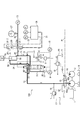
- FIG. It is a figure which shows the wheel loader incorporating the hydraulic circuit of Example 1 of this invention. It is a figure which shows the hydraulic circuit in Example 1.
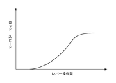
- FIG. It is a graph which shows the relationship between a lever operation amount and a pilot secondary pressure. It is a graph which shows the relationship between lever operation amount and rod speed. It is a graph which shows the relationship between the electric signal of a pump flow control valve, and a spool opening degree. It is a figure explaining a pressure accumulation state. It is a figure explaining a regeneration state. It is a table
- a hydraulic circuit 130 as a fluid pressure circuit according to the first embodiment is a hydraulic circuit that controls a stroke of a cylinder device in accordance with an operation command to a work machine, a construction machine, a cargo handling vehicle, an automobile, and the like.
- the wheel illustrated in FIG. It is incorporated in the power train of the loader 100.
- the wheel loader 100 is mainly composed of a vehicle body 101, a traveling wheel 102, a work arm 103, a hydraulic cylinder 104, and a bucket 105 into which gravel or the like is placed.
- the vehicle body 101 is provided with an engine 110 such as an engine, a traveling fluid circuit 120, a hydraulic cylinder 104, and a working hydraulic circuit 130 that drives the hydraulic cylinder 5 that is a cylinder device.
- the hydraulic circuit 130 mainly includes a main hydraulic pump 2 as a fixed displacement type fixed displacement pump driven by a drive mechanism 1 such as an engine or an electric motor, a pilot hydraulic pump 3, and direction switching.
- a valve 4 a hydraulic cylinder 5 as a fluid pressure actuator, a tank 11, an electromagnetic proportional flow control valve 26 as an accumulator flow control valve for an accumulator 27, an accumulator 27, a controller 28, a pressure sensor 33, a main It comprises an electromagnetic proportional flow control valve 40 as a pump flow control valve for the hydraulic pump 2.
- the main hydraulic pump 2 is connected to a drive mechanism 1 such as an internal combustion engine, and is rotationally driven by power from the drive mechanism 1 to supply pressure oil downstream through the oil passage 12.
- a drive mechanism 1 such as an internal combustion engine
- the pressure oil discharged from the main hydraulic pump 2 flows into the direction switching valve 4 through the oil passages 12 and 13.
- the directional switching valve 4 is a 6-port 3-position open center type switching valve. When the spool is in the neutral position, the entire amount of the pressure oil discharged from the main hydraulic pump 2 flows to the tank 11 through the oil passage 14. ing.
- a relief valve 7 is installed in the main circuit including the main hydraulic pump 2, and when the rod 5a of the hydraulic cylinder 5 reaches the end of expansion or contraction, a sudden load is applied to the hydraulic cylinder 5, and the circuit The inside of the circuit is prevented from being damaged due to abnormally high pressure, and high pressure oil discharged from the relief valve 7 is discharged to the tank 11 through the oil passage 17.
- the pilot hydraulic pump 3 is connected to the drive mechanism 1 and is rotationally driven by power from the drive mechanism 1 to supply pressure oil to the remote control valve 6 on the downstream side through the oil passage 18. is doing.
- the relief valve 8 is installed, and when the remote control valve 6 is not operated, the pressure oil is supplied to the oil passages 19 and 20 and the relief valve. 8 is discharged to the tank 11.
- the remote control valve 6 is a variable pressure reducing valve. By operating the operation lever 6-1 back and forth, the secondary pressure pressure oil that increases in proportion to the lever operation amount as shown in FIG.
- the signals are supplied to the signal ports 4A and 4B of the direction switching valve 4 through the paths 21 and 22, respectively. In this way, the direction switching valve 4 is switched to the “extended” and “contracted” positions of the hydraulic cylinder 5.
- the electromagnetic proportional flow control valve 26 is a two-port, three-position type normally closed electromagnetic proportional flow control valve.
- a check valve that allows only the flow toward the accumulator 27 at the input position 26a and a hydraulic cylinder 5 at the output position 26b are provided.
- Built-in check valve that allows only flow to the side.
- the electromagnetic proportional flow control valve 40 is a three-port two-position type normally open electromagnetic proportional control valve, and the pressure oil discharged from the main hydraulic pump 2 to the oil passage 12 can be changed into two systems of an oil passage 13 and an oil passage 42. 5 and has the opening characteristics shown in FIG. 5.
- the neutral position 40 a the oil passage 12 and the oil passage 13 are communicated, and the oil passage 42 is closed. Yes.
- the switch is gradually and variably switched to the switching position 40b according to the amount of change in the electrical signal, for example, the amount of power. .
- the amount of change is equal to or greater than the predetermined amount, it is completely switched to the switching position 40b, the oil passage 12 and the oil passage 13 are closed, and the oil passage 12 communicates with the tank 11 via the oil passage 42. Yes.
- the relationship between the lever operation amount when the operation lever 6-1 is operated in the extension direction A and the extension speed of the rod of the hydraulic cylinder 5 is a characteristic curve as shown in FIG.
- the direction switching valve 4 is configured such that the spool strokes approximately in proportion to the pilot secondary pressure of the remote control valve 6, and has an opening characteristic in which the opening amount increases in accordance with the spool stroke. As the opening amount increases, the amount of pressure oil supplied to the hydraulic cylinder 5 increases, and the operating speed of the rod 5a of the hydraulic cylinder 5 increases. That is, the rod speed can be controlled according to the operation amount of the operation lever 6-1.
- the controller 28 may accumulator can judged to be the following operation to the accumulator 27 if the pressure in the accumulator 27 is less than the high predetermined value P H I do. Incidentally, if the pressure in the accumulator 27 is more highly prescribed value P H accumulator does not perform pressure accumulation was determined to be unnecessary.
- the direction switching valve 4 is switched to the contracted position, and the pressure oil from the main hydraulic pump 2 is switched to the oil passages 12, 13 and the direction switching.
- the oil flows into the rod chamber 5B of the hydraulic cylinder through the oil passage of the valve 4 and the oil passage 24, and the oil in the bottom chamber 5A passes through the oil passage 23 and the oil passage 25 through the throttle passage of the direction switching valve 4. It is discharged to the tank 11 through.
- an electric signal corresponding to the pressure Py from the pressure sensor 10 installed on the pilot signal oil passage 22 is input to the controller 28, so that the pressure Py is adjusted by an arithmetic circuit mounted in the controller 28 in advance.
- the corresponding electric signal Sy is input to the electromagnetic proportional flow control valve 26 through the electric signal line 31, and gradually switches to the input position 26a according to the change amount of the electric signal Sy, and the discharged oil from the bottom chamber 5A
- a part of the pressure is accumulated in the accumulator 27 through an oil passage 29 as a branch passage, a check valve of the electromagnetic proportional flow control valve 26, and an oil passage 30 as a branch passage.
- an electric signal corresponding to the pressure Px from the pressure sensor 9 and an electric signal corresponding to the pressure Pz from the pressure sensor 33 are input to the controller 28, so that the pressure is calculated by an arithmetic circuit mounted in the controller 28 in advance.
- An electric signal Pxz corresponding to Px, Pz is input to the electromagnetic proportional flow control valve 26 through the electric signal line 32, and gradually switches to the output position 26b side according to the change amount of the electric signal Pxz.
- the accumulated oil variably joins the oil passage 23 through the oil passage 30, the check valve of the electromagnetic proportional flow control valve 26, and the oil passage 29, and is supplied to the bottom chamber 5A of the hydraulic cylinder.
- the pressure oil accumulated in the accumulator 27 is regenerated.
- the electrical signal Pxz is input from the controller 28 to the solenoid unit 40-1 of the electromagnetic proportional flow rate control valve 40 through the electrical signal line 41, and is gradually switched to the switching position 40b according to the change amount of the electrical signal Pxz.
- the opening between the oil passage 12 and the oil passage 13 is variably gradually reduced, and the opening between the oil passage 12 and the oil passage 42 is variably gradually increased, and the electric signal Pxz
- the change amount is large and the switching position 40b is completely switched, the oil passage 12 and the oil passage 13 are shut off, and the oil passage 12 is completely communicated with the tank 11 through the oil passage 42.
- the oil passage 12 of the main hydraulic pump 2 is branched into two systems of an oil passage 13 and an oil passage 42 by an electromagnetic proportional flow control valve 40, and the discharge oil amount Q12 of the oil passage 12 is variably oil.
- the oil amount Q5A is the same as the oil amount that flows into the bottom chamber 5A during the normal extension operation, and the oil amount Q29 and the oil amount Q42 are complementary. That is, the electromagnetic proportional flow control valve 26 and the electromagnetic proportional flow control valve 40 have complementary characteristics with respect to the change amount of the electric signal Pxz.
- the oil amount Q29 supplied from the accumulator 27 to the bottom chamber 5A and the oil amount discharged from the oil passage 12 to the oil passage 42 via the electromagnetic proportional flow control valve 40 when the direction switching valve 4 is fully opened. It is the same as Q42 (Q29 Q42).
- f (Px) is a function of the pressure corresponding to the operation amount of the operation lever 6-1, and is approximately proportional to the operation amount and becomes 1 when the operation amount exceeds a predetermined value.
- the variation of the electrical signal Pxz to be output to the electromagnetic proportional flow rate control valve 26, when the pressure Pz is above the high predetermined value P H is only likewise pressure Px and during shrinkage
- the corresponding amount ⁇ Px and the pressure Pz are equal to or higher than the low predetermined value P L and lower than the high predetermined value P H
- the amount ⁇ Pz and the pressure Pz according to only the pressure Pz are lower than the low predetermined value P L
- the amount is zero.
- it can regenerate also when the pressure accumulated in accumulator 27 is comparatively low, and is excellent in energy efficiency. It may be caused to the regeneration only when the pressure in the accumulator 27 is greater than or equal to the high predetermined value P H.
- control of the electromagnetic proportional flow control valves 26 and 40 can be simplified.
- the accumulated oil in the accumulator 27 can be electromagnetically used while using the fixed displacement main hydraulic pump 2.
- the proportional flow control valve 26 the oil is regenerated in the bottom chamber 5 ⁇ / b> A of the hydraulic cylinder 5, and at the same time, the discharge oil of the main hydraulic pump 2 is communicated to the low-pressure tank 11 by the electromagnetic proportional flow control valve 40.
- the discharge pressure is reduced.
- the relationship between the pump output E, the pump discharge pressure P, and the discharge flow rate Q is as follows: E ⁇ P ⁇ Q Therefore, the output (load) of the main hydraulic pump 2 is reduced, and the system can save energy.
- a part of the return oil from the bottom chamber 5A is accumulated in the accumulator 27 when the rod 5a is contracted, and this accumulated oil is regenerated in the bottom chamber 5A when the rod 5a is extended.
- a part of the return oil from the rod chamber 5B may be accumulated in the accumulator 27, and a part of the return oil from the bottom chamber 5A and the rod chamber 5B both when the rod 5a is contracted and extended. May be accumulated in the accumulator 27.
- the fluid pressure actuator may be other than a hydraulic cylinder.
- a part of the return oil during braking of the hydraulic motor is accumulated in an accumulator, and the accumulated oil is regenerated during acceleration of the hydraulic motor.
- the present invention can be applied to any circuit that accumulates pressure in an accumulator and regenerates it in a hydraulic circuit using a capacity type main hydraulic pump.
- electromagnetic proportional flow control valves 26 and 40 are not limited to a configuration that performs switching operation by electricity, but may be valves that perform hydraulic operation.
- the function of the electromagnetic proportional flow control valve 40 may be incorporated in the direction switching valve 4.
- the direction switching valve 4 is preferably controlled by both the pilot hydraulic pressure and the electrical signal.
Landscapes
- Engineering & Computer Science (AREA)
- General Engineering & Computer Science (AREA)
- Mechanical Engineering (AREA)
- Physics & Mathematics (AREA)
- Fluid Mechanics (AREA)
- Mining & Mineral Resources (AREA)
- Civil Engineering (AREA)
- Structural Engineering (AREA)
- Chemical & Material Sciences (AREA)
- Analytical Chemistry (AREA)
- Fluid-Pressure Circuits (AREA)
Abstract
Description
流体を貯蔵するタンクと、前記タンク内の流体を加圧する固定容量ポンプと、前記固定容量ポンプから吐出された加圧流体によって作動する流体圧アクチュエータと、前記固定容量ポンプと前記流体圧アクチュエータとの間に配置され前記加圧流体の流路を切り換える方向切換弁とを備え、操作指令に応じて前記流体圧アクチュエータを制御する流体圧回路であって、
前記流体圧アクチュエータと前記方向切換弁とを接続する接続流路から分岐する分岐流路に設けられたアキュムレータと、
前記接続流路と前記アキュムレータとの間に配置されたアキュムレータ流量制御弁と、
前記流体圧アクチュエータと前記固定容量ポンプとの間に配置され、該固定容量ポンプから吐出された加圧流体を前記タンク側の系統と前記流体圧アクチュエータ側の系統との2系統に流量を可変して分岐するポンプ流量制御弁と、を備えることを特徴としている。
この特徴によれば、ポンプ流量制御弁は入力された加圧流体を2系統に流量を可変して出力するから、構造の簡単な固定容量ポンプを用いながら、操作指令に応じて円滑に流体圧アクチュエータを制御可能となり、かつアキュムレータの蓄圧流体により流体圧アクチュエータを作動させることが可能でありエネルギを有効に活用できる。また、流体圧回路は、固定容量ポンプと方向切換弁とアキュムレータ流量制御弁とポンプ流量切換弁とから主に構成されているから安価にできる。
これによれば、スプールのストローク制御により流量を調整できるため構造が簡単である。
これによれば、流体圧アクチュエータを円滑に制御できるとともに回生作動時の固定容量ポンプの負荷を小さくできる。
これによれば、操作指令に対する流体圧アクチュエータの動作特性を通常の制御時と回生の制御時に合わせることができる。
これによれば、アキュムレータに蓄圧されている流体の実際の圧力を反映できるため、さらに円滑に制御可能となる。
これによれば、ポンプ流量制御弁は方向切換弁と別体であるから、方向切換弁の構造は複雑にならない。
操作レバー6-1を伸び方向Aに操作した時のレバー操作量と油圧シリンダ5のロッドの伸びスピードの関係は、図4に示すような特性カーブとなっている。方向切換弁4は、リモコン弁6のパイロット二次圧に略比例してスプールがストロークするように構成されており、スプールストロークに応じてその開口量が増加する開口特性を有しているため、開口量の増加に伴い油圧シリンダ5への圧油の供給油量が増え、油圧シリンダ5のロッド5aの作動スピードが増すようになっている。つまり、操作レバー6-1の操作量に応じてロッドスピードをコントロールすることができる。
一方で、操作レバー6-1が縮み方向Bに操作されて方向切換弁4が縮み位置に切り換わると、メイン油圧ポンプ2からの圧油は油路12,13,15,24を通って油圧シリンダ5のロッド室5Bに流入し、ボトム室5A内の油が接続流路としての油路23を通り、更に方向切換弁4を介して油路25を通ってタンク11に排出される。これにより、油圧シリンダ5のロッド5aは縮み方向に移動する。
リモコン弁6の操作レバー6-1を縮み方向Bに操作された際に、コントローラ28はアキュムレータ27の圧力が高所定値PH未満であればアキュムレータ27への蓄圧が可能と判断し以下の動作を行う。なお、アキュムレータ27の圧力が高所定値PH以上であれば蓄圧が不要であると判断して蓄圧を行わない。
リモコン弁6の操作レバー6-1を伸び方向Aに操作された際に、コントローラ28はアキュムレータ27の圧力が低所定値PL以上であればアキュムレータ27に蓄圧された圧油の回生が可能と判断し以下の動作を行う。なお、アキュムレータ27の圧力が低所定値PL未満であれば回生を行わない。また、高所定値PHは低所定値PLよりも高い圧力である。
なお、アキュムレータ27の圧力が高所定値PH以上であるときのみ回生をさせるようにしてもよい。このようにすることで、電磁比例流量制御弁26,40の制御を単純にできる。
E∝P×Q
であるため、メイン油圧ポンプ2の出力(負荷)が低減され、システムの省エネを図ることができる。
4 方向切換弁
5 油圧シリンダ(流体圧アクチュエータ)
5A ボトム室
5B ロッド室
5a ロッド
6 リモコン弁
6-1 操作レバー
11 タンク
23 油路(接続流路)
26 電磁比例流量制御弁(アキュムレータ流量制御弁)
27 アキュムレータ
28 コントローラ
29,30 油路(分岐流路)
33 圧力センサ
40 電磁比例流量制御弁(ポンプ流量制御弁)
130 油圧回路(流体圧回路)
Claims (6)
- 流体を貯蔵するタンクと、前記タンク内の流体を加圧する固定容量ポンプと、前記固定容量ポンプから吐出された加圧流体によって作動する流体圧アクチュエータと、前記固定容量ポンプと前記流体圧アクチュエータとの間に配置され前記加圧流体の流路を切り換える方向切換弁とを備え、操作指令に応じて前記流体圧アクチュエータを制御する流体圧回路であって、
前記流体圧アクチュエータと前記方向切換弁とを接続する接続流路から分岐する分岐流路に設けられたアキュムレータと、
前記接続流路と前記アキュムレータとの間に配置されたアキュムレータ流量制御弁と、
前記流体圧アクチュエータと前記固定容量ポンプとの間に配置され、該固定容量ポンプから吐出された加圧流体を前記タンク側の系統と前記流体圧アクチュエータ側の系統との2系統に流量を可変して分岐するポンプ流量制御弁と、を備える流体圧回路。 - 前記ポンプ流量制御弁はスプール弁である請求項1に記載の流体圧回路。
- 前記アキュムレータにより前記流体圧アクチュエータを作動させる際に、前記ポンプ流量制御弁を関連して制御する制御部を有する請求項1または2に記載の流体圧回路。
- 前記アキュムレータ流量制御弁は、流量を可変に切り換える比例弁であって、前記制御部は、前記アキュムレータ流量制御弁と前記ポンプ流量制御弁とに相補的な操作指令を出力する請求項3に記載の流体圧回路。
- 前記アキュムレータの圧力を検出するセンサが配置されている請求項1ないし4のいずれかに記載の流体圧回路。
- 前記ポンプ流量制御弁は、前記方向切換弁と前記固定容量ポンプとの間に配置されている請求項1ないし5のいずれかに記載の流体圧回路。
Priority Applications (4)
| Application Number | Priority Date | Filing Date | Title |
|---|---|---|---|
| JP2020513214A JP7210553B2 (ja) | 2018-04-09 | 2019-04-03 | 流体圧回路 |
| EP19785881.4A EP3779211B1 (en) | 2018-04-09 | 2019-04-03 | Fluid pressure circuit |
| US16/981,498 US11371535B2 (en) | 2018-04-09 | 2019-04-03 | Fluid pressure circuit |
| CN201980019517.6A CN111868393A (zh) | 2018-04-09 | 2019-04-03 | 流体压回路 |
Applications Claiming Priority (2)
| Application Number | Priority Date | Filing Date | Title |
|---|---|---|---|
| JP2018074578 | 2018-04-09 | ||
| JP2018-074578 | 2018-04-09 |
Publications (1)
| Publication Number | Publication Date |
|---|---|
| WO2019198579A1 true WO2019198579A1 (ja) | 2019-10-17 |
Family
ID=68164622
Family Applications (1)
| Application Number | Title | Priority Date | Filing Date |
|---|---|---|---|
| PCT/JP2019/014728 Ceased WO2019198579A1 (ja) | 2018-04-09 | 2019-04-03 | 流体圧回路 |
Country Status (5)
| Country | Link |
|---|---|
| US (1) | US11371535B2 (ja) |
| EP (1) | EP3779211B1 (ja) |
| JP (1) | JP7210553B2 (ja) |
| CN (1) | CN111868393A (ja) |
| WO (1) | WO2019198579A1 (ja) |
Cited By (8)
| Publication number | Priority date | Publication date | Assignee | Title |
|---|---|---|---|---|
| CN111536085A (zh) * | 2020-06-06 | 2020-08-14 | 华东交通大学 | 一种可能量回收的足式液压机器人液压控制系统 |
| CN113217486A (zh) * | 2020-02-04 | 2021-08-06 | 纳博特斯克有限公司 | 流体压系统和流体压的控制方法 |
| CN114846256A (zh) * | 2019-12-20 | 2022-08-02 | 波克兰液压工业设备公司 | 改进的开放型的液压辅助系统 |
| JP2023031434A (ja) * | 2021-08-25 | 2023-03-09 | ヤンマーホールディングス株式会社 | 電動式作業機械 |
| WO2023162884A1 (ja) | 2022-02-24 | 2023-08-31 | イーグル工業株式会社 | 流体圧回路 |
| WO2023189681A1 (ja) * | 2022-03-31 | 2023-10-05 | 日立建機株式会社 | 作業機械 |
| JP2023170779A (ja) * | 2022-05-20 | 2023-12-01 | 株式会社不二越 | 油圧システム |
| JP2024024902A (ja) * | 2022-08-10 | 2024-02-26 | 古河ユニック株式会社 | 油圧制御装置 |
Families Citing this family (2)
| Publication number | Priority date | Publication date | Assignee | Title |
|---|---|---|---|---|
| CN115289108B (zh) * | 2022-06-28 | 2026-02-06 | 中联重科股份有限公司 | 单主泵泵送液压系统和混凝土泵送设备 |
| DE102024200630B4 (de) * | 2024-01-24 | 2025-09-04 | Hawe Hydraulik Se | Hydrauliksystem und Fahrgast-Rückhaltesystem |
Citations (6)
| Publication number | Priority date | Publication date | Assignee | Title |
|---|---|---|---|---|
| JPS6246002A (ja) * | 1985-08-06 | 1987-02-27 | マンネスマン・レツクスロス・ゲ−・エム・ベ−・ハ− | 印加圧力を有する駆動系のための制御装置 |
| JP2005308126A (ja) * | 2004-04-22 | 2005-11-04 | Saxa Inc | 液圧装置 |
| JP2006308077A (ja) * | 2005-03-31 | 2006-11-09 | Honda Motor Co Ltd | 油圧回路の制御装置 |
| JP2008089024A (ja) * | 2006-09-29 | 2008-04-17 | Kobelco Contstruction Machinery Ltd | 油圧アクチュエータの制御装置及びこれを備えた作業機械 |
| JP2008095788A (ja) | 2006-10-11 | 2008-04-24 | Shin Caterpillar Mitsubishi Ltd | エネルギー回生システム |
| JP2017015130A (ja) * | 2015-06-29 | 2017-01-19 | イーグル工業株式会社 | 流体回路 |
Family Cites Families (10)
| Publication number | Priority date | Publication date | Assignee | Title |
|---|---|---|---|---|
| FR2129156A5 (ja) * | 1971-03-17 | 1972-10-27 | Citroen Sa | |
| JPS596403A (ja) * | 1982-06-30 | 1984-01-13 | Caterpillar Mitsubishi Ltd | 油圧式アクチユエ−タ自動制御装置 |
| DE4106845A1 (de) * | 1991-03-04 | 1992-09-24 | Deere & Co | Hydrauliksystem zur steuerung einer einen verbraucher bewegenden kraft |
| JP2003148404A (ja) | 2001-11-07 | 2003-05-21 | Teijin Seiki Co Ltd | 電気油圧モータおよび油圧駆動方法 |
| DE10227966A1 (de) * | 2002-06-22 | 2004-01-08 | Deere & Company, Moline | Hydraulische Steueranordnung für eine mobile Arbeitsmaschine |
| DE102005038333A1 (de) * | 2005-08-11 | 2007-02-15 | Deere & Company, Moline | Hydraulische Anordnung |
| DE112008000200B4 (de) * | 2007-01-18 | 2021-08-26 | Hitachi Construction Machinery Co., Ltd. | Schwingungsunterdrückungsvorrichtung für hydraulische Arbeitsmaschine und hydraulische Arbeitsmaschine |
| US20140238007A1 (en) * | 2013-02-27 | 2014-08-28 | Caterpillar Inc. | Hydraulic Ride Control System |
| JP6205339B2 (ja) * | 2014-08-01 | 2017-09-27 | 株式会社神戸製鋼所 | 油圧駆動装置 |
| JP6549543B2 (ja) * | 2016-09-29 | 2019-07-24 | 日立建機株式会社 | 作業機械の油圧駆動装置 |
-
2019
- 2019-04-03 CN CN201980019517.6A patent/CN111868393A/zh active Pending
- 2019-04-03 WO PCT/JP2019/014728 patent/WO2019198579A1/ja not_active Ceased
- 2019-04-03 US US16/981,498 patent/US11371535B2/en active Active
- 2019-04-03 JP JP2020513214A patent/JP7210553B2/ja active Active
- 2019-04-03 EP EP19785881.4A patent/EP3779211B1/en active Active
Patent Citations (6)
| Publication number | Priority date | Publication date | Assignee | Title |
|---|---|---|---|---|
| JPS6246002A (ja) * | 1985-08-06 | 1987-02-27 | マンネスマン・レツクスロス・ゲ−・エム・ベ−・ハ− | 印加圧力を有する駆動系のための制御装置 |
| JP2005308126A (ja) * | 2004-04-22 | 2005-11-04 | Saxa Inc | 液圧装置 |
| JP2006308077A (ja) * | 2005-03-31 | 2006-11-09 | Honda Motor Co Ltd | 油圧回路の制御装置 |
| JP2008089024A (ja) * | 2006-09-29 | 2008-04-17 | Kobelco Contstruction Machinery Ltd | 油圧アクチュエータの制御装置及びこれを備えた作業機械 |
| JP2008095788A (ja) | 2006-10-11 | 2008-04-24 | Shin Caterpillar Mitsubishi Ltd | エネルギー回生システム |
| JP2017015130A (ja) * | 2015-06-29 | 2017-01-19 | イーグル工業株式会社 | 流体回路 |
Non-Patent Citations (1)
| Title |
|---|
| See also references of EP3779211A4 |
Cited By (13)
| Publication number | Priority date | Publication date | Assignee | Title |
|---|---|---|---|---|
| CN114846256B (zh) * | 2019-12-20 | 2024-06-21 | 波克兰液压工业设备公司 | 改进的开放型的液压辅助系统 |
| CN114846256A (zh) * | 2019-12-20 | 2022-08-02 | 波克兰液压工业设备公司 | 改进的开放型的液压辅助系统 |
| CN113217486A (zh) * | 2020-02-04 | 2021-08-06 | 纳博特斯克有限公司 | 流体压系统和流体压的控制方法 |
| CN111536085A (zh) * | 2020-06-06 | 2020-08-14 | 华东交通大学 | 一种可能量回收的足式液压机器人液压控制系统 |
| JP2023031434A (ja) * | 2021-08-25 | 2023-03-09 | ヤンマーホールディングス株式会社 | 電動式作業機械 |
| JP7588050B2 (ja) | 2021-08-25 | 2024-11-21 | ヤンマーホールディングス株式会社 | 電動式作業機械 |
| WO2023162884A1 (ja) | 2022-02-24 | 2023-08-31 | イーグル工業株式会社 | 流体圧回路 |
| WO2023189681A1 (ja) * | 2022-03-31 | 2023-10-05 | 日立建機株式会社 | 作業機械 |
| JPWO2023189681A1 (ja) * | 2022-03-31 | 2023-10-05 | ||
| JP7661615B2 (ja) | 2022-03-31 | 2025-04-14 | 日立建機株式会社 | 作業機械 |
| US12320098B2 (en) | 2022-03-31 | 2025-06-03 | Hitachi Construction Machinery Co., Ltd. | Work machine |
| JP2023170779A (ja) * | 2022-05-20 | 2023-12-01 | 株式会社不二越 | 油圧システム |
| JP2024024902A (ja) * | 2022-08-10 | 2024-02-26 | 古河ユニック株式会社 | 油圧制御装置 |
Also Published As
| Publication number | Publication date |
|---|---|
| EP3779211B1 (en) | 2025-05-21 |
| US20210364015A1 (en) | 2021-11-25 |
| CN111868393A (zh) | 2020-10-30 |
| EP3779211A4 (en) | 2022-01-05 |
| US11371535B2 (en) | 2022-06-28 |
| JP7210553B2 (ja) | 2023-01-23 |
| EP3779211A1 (en) | 2021-02-17 |
| JPWO2019198579A1 (ja) | 2021-05-13 |
Similar Documents
| Publication | Publication Date | Title |
|---|---|---|
| JP7210553B2 (ja) | 流体圧回路 | |
| JP5574375B2 (ja) | エネルギ回生用制御回路および作業機械 | |
| US9228323B2 (en) | Control system for construction machine | |
| US5852934A (en) | Fluid joining device for power construction vehicles | |
| JP5378061B2 (ja) | ハイブリッド建設機械の制御装置 | |
| US8806860B2 (en) | Hybrid construction machine | |
| JP3816893B2 (ja) | 油圧駆動装置 | |
| EP3032112B1 (en) | Shovel | |
| JP5873684B2 (ja) | 作業車両の油圧駆動装置 | |
| JP7404258B2 (ja) | 流体回路 | |
| JP2017015130A (ja) | 流体回路 | |
| JP6974366B2 (ja) | 流体圧回路 | |
| WO2009131085A1 (ja) | ハイブリッド建設機械の制御装置 | |
| JP5197479B2 (ja) | ハイブリッド建設機械 | |
| JP2017125537A (ja) | ハイブリッド作業機の制御システム | |
| JP5602034B2 (ja) | ホイール式走行作業車の走行駆動回路装置 | |
| WO2023162884A1 (ja) | 流体圧回路 | |
| US20250180043A1 (en) | Fluid pressure circuit | |
| US12292061B2 (en) | Fluid pressure circuit | |
| JP2013044398A (ja) | 油圧駆動システム | |
| EP4624765A1 (en) | Hydraulic pressure circuit | |
| JP4926627B2 (ja) | 電油システム | |
| WO2024111448A1 (ja) | 流体圧回路 |
Legal Events
| Date | Code | Title | Description |
|---|---|---|---|
| 121 | Ep: the epo has been informed by wipo that ep was designated in this application |
Ref document number: 19785881 Country of ref document: EP Kind code of ref document: A1 |
|
| ENP | Entry into the national phase |
Ref document number: 2020513214 Country of ref document: JP Kind code of ref document: A |
|
| NENP | Non-entry into the national phase |
Ref country code: DE |
|
| ENP | Entry into the national phase |
Ref document number: 2019785881 Country of ref document: EP Effective date: 20201109 |
|
| WWG | Wipo information: grant in national office |
Ref document number: 2019785881 Country of ref document: EP |