WO2019198643A1 - 部品整送装置 - Google Patents
部品整送装置 Download PDFInfo
- Publication number
- WO2019198643A1 WO2019198643A1 PCT/JP2019/015174 JP2019015174W WO2019198643A1 WO 2019198643 A1 WO2019198643 A1 WO 2019198643A1 JP 2019015174 W JP2019015174 W JP 2019015174W WO 2019198643 A1 WO2019198643 A1 WO 2019198643A1
- Authority
- WO
- WIPO (PCT)
- Prior art keywords
- component
- branch
- passage
- branch passage
- welding nut
- Prior art date
- Legal status (The legal status is an assumption and is not a legal conclusion. Google has not performed a legal analysis and makes no representation as to the accuracy of the status listed.)
- Ceased
Links
Images


Classifications
-
- B—PERFORMING OPERATIONS; TRANSPORTING
- B65—CONVEYING; PACKING; STORING; HANDLING THIN OR FILAMENTARY MATERIAL
- B65G—TRANSPORT OR STORAGE DEVICES, e.g. CONVEYORS FOR LOADING OR TIPPING, SHOP CONVEYOR SYSTEMS OR PNEUMATIC TUBE CONVEYORS
- B65G47/00—Article or material-handling devices associated with conveyors; Methods employing such devices
- B65G47/02—Devices for feeding articles or materials to conveyors
- B65G47/04—Devices for feeding articles or materials to conveyors for feeding articles
- B65G47/12—Devices for feeding articles or materials to conveyors for feeding articles from disorderly-arranged article piles or from loose assemblages of articles
- B65G47/14—Devices for feeding articles or materials to conveyors for feeding articles from disorderly-arranged article piles or from loose assemblages of articles arranging or orientating the articles by mechanical or pneumatic means during feeding
-
- B—PERFORMING OPERATIONS; TRANSPORTING
- B65—CONVEYING; PACKING; STORING; HANDLING THIN OR FILAMENTARY MATERIAL
- B65G—TRANSPORT OR STORAGE DEVICES, e.g. CONVEYORS FOR LOADING OR TIPPING, SHOP CONVEYOR SYSTEMS OR PNEUMATIC TUBE CONVEYORS
- B65G47/00—Article or material-handling devices associated with conveyors; Methods employing such devices
- B65G47/22—Devices influencing the relative position or the attitude of articles during transit by conveyors
- B65G47/24—Devices influencing the relative position or the attitude of articles during transit by conveyors orientating the articles
- B65G47/256—Devices influencing the relative position or the attitude of articles during transit by conveyors orientating the articles removing incorrectly orientated articles
-
- B—PERFORMING OPERATIONS; TRANSPORTING
- B23—MACHINE TOOLS; METAL-WORKING NOT OTHERWISE PROVIDED FOR
- B23K—SOLDERING OR UNSOLDERING; WELDING; CLADDING OR PLATING BY SOLDERING OR WELDING; CUTTING BY APPLYING HEAT LOCALLY, e.g. FLAME CUTTING; WORKING BY LASER BEAM
- B23K11/00—Resistance welding; Severing by resistance heating
- B23K11/002—Resistance welding; Severing by resistance heating specially adapted for particular articles or work
- B23K11/004—Welding of a small piece to a large or broad piece
- B23K11/0046—Welding of a small piece to a large or broad piece the extremity of a small piece being welded to a base, e.g. cooling studs or fins to tubes or plates
- B23K11/0053—Stud welding, i.e. resistive
-
- B—PERFORMING OPERATIONS; TRANSPORTING
- B23—MACHINE TOOLS; METAL-WORKING NOT OTHERWISE PROVIDED FOR
- B23P—METAL-WORKING NOT OTHERWISE PROVIDED FOR; COMBINED OPERATIONS; UNIVERSAL MACHINE TOOLS
- B23P19/00—Machines for simply fitting together or separating metal parts or objects, or metal and non-metal parts, whether or not involving some deformation; Tools or devices therefor so far as not provided for in other classes
- B23P19/001—Article feeders for assembling machines
- B23P19/002—Article feeders for assembling machines orientating the articles
-
- B—PERFORMING OPERATIONS; TRANSPORTING
- B65—CONVEYING; PACKING; STORING; HANDLING THIN OR FILAMENTARY MATERIAL
- B65G—TRANSPORT OR STORAGE DEVICES, e.g. CONVEYORS FOR LOADING OR TIPPING, SHOP CONVEYOR SYSTEMS OR PNEUMATIC TUBE CONVEYORS
- B65G47/00—Article or material-handling devices associated with conveyors; Methods employing such devices
- B65G47/52—Devices for transferring articles or materials between conveyors i.e. discharging or feeding devices
- B65G47/68—Devices for transferring articles or materials between conveyors i.e. discharging or feeding devices adapted to receive articles arriving in one layer from one conveyor lane and to transfer them in individual layers to more than one conveyor lane or to one broader conveyor lane, or vice versa, e.g. combining the flows of articles conveyed by more than one conveyor
- B65G47/71—Devices for transferring articles or materials between conveyors i.e. discharging or feeding devices adapted to receive articles arriving in one layer from one conveyor lane and to transfer them in individual layers to more than one conveyor lane or to one broader conveyor lane, or vice versa, e.g. combining the flows of articles conveyed by more than one conveyor the articles being discharged or distributed to several distinct separate conveyors or to a broader conveyor lane
-
- B—PERFORMING OPERATIONS; TRANSPORTING
- B65—CONVEYING; PACKING; STORING; HANDLING THIN OR FILAMENTARY MATERIAL
- B65G—TRANSPORT OR STORAGE DEVICES, e.g. CONVEYORS FOR LOADING OR TIPPING, SHOP CONVEYOR SYSTEMS OR PNEUMATIC TUBE CONVEYORS
- B65G11/00—Chutes
- B65G11/08—Chutes with discontinuous guiding surfaces, e.g. arranged in zigzag or cascade formation
- B65G11/081—Chutes with discontinuous guiding surfaces, e.g. arranged in zigzag or cascade formation for articles
-
- B—PERFORMING OPERATIONS; TRANSPORTING
- B65—CONVEYING; PACKING; STORING; HANDLING THIN OR FILAMENTARY MATERIAL
- B65G—TRANSPORT OR STORAGE DEVICES, e.g. CONVEYORS FOR LOADING OR TIPPING, SHOP CONVEYOR SYSTEMS OR PNEUMATIC TUBE CONVEYORS
- B65G2201/00—Indexing codes relating to handling devices, e.g. conveyors, characterised by the type of product or load being conveyed or handled
- B65G2201/02—Articles
- B65G2201/0214—Articles of special size, shape or weigh
-
- B—PERFORMING OPERATIONS; TRANSPORTING
- B65—CONVEYING; PACKING; STORING; HANDLING THIN OR FILAMENTARY MATERIAL
- B65G—TRANSPORT OR STORAGE DEVICES, e.g. CONVEYORS FOR LOADING OR TIPPING, SHOP CONVEYOR SYSTEMS OR PNEUMATIC TUBE CONVEYORS
- B65G43/00—Control devices, e.g. for safety, warning or fault-correcting
- B65G43/08—Control devices operated by article or material being fed, conveyed or discharged
-
- B—PERFORMING OPERATIONS; TRANSPORTING
- B65—CONVEYING; PACKING; STORING; HANDLING THIN OR FILAMENTARY MATERIAL
- B65G—TRANSPORT OR STORAGE DEVICES, e.g. CONVEYORS FOR LOADING OR TIPPING, SHOP CONVEYOR SYSTEMS OR PNEUMATIC TUBE CONVEYORS
- B65G47/00—Article or material-handling devices associated with conveyors; Methods employing such devices
- B65G47/02—Devices for feeding articles or materials to conveyors
- B65G47/04—Devices for feeding articles or materials to conveyors for feeding articles
- B65G47/12—Devices for feeding articles or materials to conveyors for feeding articles from disorderly-arranged article piles or from loose assemblages of articles
- B65G47/14—Devices for feeding articles or materials to conveyors for feeding articles from disorderly-arranged article piles or from loose assemblages of articles arranging or orientating the articles by mechanical or pneumatic means during feeding
- B65G47/1407—Devices for feeding articles or materials to conveyors for feeding articles from disorderly-arranged article piles or from loose assemblages of articles arranging or orientating the articles by mechanical or pneumatic means during feeding the articles being fed from a container, e.g. a bowl
-
- B—PERFORMING OPERATIONS; TRANSPORTING
- B65—CONVEYING; PACKING; STORING; HANDLING THIN OR FILAMENTARY MATERIAL
- B65G—TRANSPORT OR STORAGE DEVICES, e.g. CONVEYORS FOR LOADING OR TIPPING, SHOP CONVEYOR SYSTEMS OR PNEUMATIC TUBE CONVEYORS
- B65G47/00—Article or material-handling devices associated with conveyors; Methods employing such devices
- B65G47/02—Devices for feeding articles or materials to conveyors
- B65G47/16—Devices for feeding articles or materials to conveyors for feeding materials in bulk
- B65G47/18—Arrangements or applications of hoppers or chutes
Definitions
- the present invention relates to a parts feeding device for feeding parts such as nuts.
- Japanese Patent Application Laid-Open No. H10-228561 discloses a component adjusting device including an introduction passage, two branch passages branched in a forked manner from the introduction passage, and a discharge passage where each branch passage joins.
- a feeding device is disclosed.
- a front-facing part is passed through one of the branch passages and a back-facing part is passed through the other of the branch passages, and each part is directed in the same direction in the discharge passage.
- the stopper is provided in the downstream part of each branch channel
- Patent Document 1 since it is necessary to provide a stopper pin, there is a problem that the number of parts increases and it takes time and effort for maintenance.
- the present invention has been made in view of such a point, and an object thereof is to smoothly join parts without providing a stopper pin at a branched portion.
- a first invention is a component feeding device that feeds the surfaces of a plurality of supplied components in the same direction, An introduction passage through which the above parts pass; A first branch passage that is provided downstream of the introduction passage and through which the component passes in a face-up state; and a second branch passage through which the component passes in a face-down state and passes through the branch passages.
- a branch part that orients the table of the above parts in the same direction, A junction that is located downstream of the branch and where the first branch passage and the second branch passage merge; While the part is stationary between the introduction passage and the branch portion, the front side and the back side of the part are discriminated, and the part discriminated to be front side is sent to the first branch passage.
- the component is a nut having a surface portion having a flat surface, a back surface portion having a flat back surface, and a protrusion formed on an outer peripheral edge of the back surface portion.
- the discrimination distribution unit is A holding portion for holding the component in a state in which the front and back surfaces of the component are oriented in a direction orthogonal to the passing direction of the component; In the holding part, comprising a contact surface that contacts the front surface or the back surface of the component, The first distance from the contact surface to the surface portion when the back surface of the component contacts the contact surface, and the contact when the surface of the component contacts the contact surface The second distance from the surface to the back surface portion is detected, and when the first distance is detected, the component is moved to the first branch passage, and when the second distance is detected, the component is moved to the second distance. It is characterized by sorting to a branch passage.
- the front surface and the back surface of the component are directed in a direction orthogonal to a direction in which the component passes in the branch portion.
- the branch portion is twisted such that the first branch passage is rotationally displaced by 180 ° compared to the upstream end portion in a cross-sectional view orthogonal to the direction in which the parts pass.
- the surface of each said part which passed the said branch part in the said junction part is orient
- 4th invention is 1st or 2nd invention, the surface and the back surface of the said component are orient
- the branch portion is configured such that the downstream end of the first branch passage is rotationally displaced at a predetermined first angle as compared to the upstream end in a cross-sectional view orthogonal to the direction in which the component passes. Twist and the second branch passage has a rotational displacement of the downstream end of the first branch passage compared to the upstream end in the cross-sectional view perpendicular to the direction in which the component passes.
- the fifth invention is characterized in that, in the fourth invention, the first angle is 90 °, and the second angle is 90 °.
- the front part and the back side of the part are discriminated in a state where the part is stationary, the part that is discriminated to be front side is transferred to the first branch portion, and the part that is determined to be the back side is It sends to 2 branch parts in order.
- the said part can be intermittently sent to the said 1st branch part or the said 2nd branch part. Therefore, in the said junction part, since the collision by said each components is suppressed, the said parts can be smoothly sent, without providing a stopper pin in the said branch part.
- the tip of the protrusion of the component contacts the contact surface.
- the first distance from the contact surface to the surface portion of the component is a dimension corresponding to the thickness including the protrusion of the component.
- the second distance from the contact surface to the back surface portion of the component is a dimension corresponding to the thickness excluding the protrusion of the component.
- the surface of the component passing through the upstream end of the first branch passage is rotationally displaced by 180 ° at the downstream end.
- the surface of the component that passes through the downstream end of the first branch passage and the surface of the component that passes through the downstream end of the second branch passage are directed in the same direction. Therefore, the components can merge at the merge portion with the surfaces of the components facing in the same direction.
- the surface of the component that passes through the upstream end of the first branch passage is rotationally displaced at a predetermined first angle at the downstream end.
- the surface of the part that passes through the upstream end of the second branch passage has a predetermined second end in the direction opposite to the rotational direction of the part that has passed through the first branch passage at the downstream end. It is rotationally displaced at an angle. Since the sum of the first angle and the second angle is 180 °, it passes through the surface of the part passing through the downstream end of the first branch passage and the downstream end of the second branch passage.
- the surface of the component is oriented in the same direction. Therefore, the components can merge at the merge portion with the surfaces of the components facing in the same direction.
- the surface of the part that passes through the upstream end of the first branch passage is rotated and displaced by 90 ° at the downstream end.
- the surface of the component that passes through the upstream end of the second branch passage is 90 ° rotationally displaced at the downstream end in a direction opposite to the direction in which the component that has passed through the first branch passage is rotationally displaced. is doing. Therefore, the surface of the component that passes through the downstream end of the first branch passage and the surface of the component that passes through the downstream end of the second branch passage are directed in the same direction.
- the difference between the time taken for the component to pass through the first branch passage and the time taken for the component to pass through the second branch passage can be reduced. Therefore, it can suppress that each said components intermittently sent to each said branch passage collides with each other in a junction part.
- FIG. 8 is a view corresponding to FIG. 7 when discriminating the orientation of the front-facing welding nut.
- FIG. 8 is a view corresponding to FIG. 7 when discriminating the orientation of the welding nut facing backward.
- FIG. 5 is a view corresponding to FIG. 4 when the front-facing welding nut is distributed.
- FIG. 5 is a view corresponding to FIG. 4 when sorting the welding nut facing downward.
- FIG. 1 and FIG. 2 show the overall configuration of the delivery device 1.
- the sheet feeding device 1 is provided in a component supply device (not shown) such as a nut feeder, for example.
- a component supply device such as a nut feeder, for example.
- an input chute (not shown) into which parts are input is provided.
- a supply head (not shown) for supplying parts to the workpiece is provided on the downstream side (lower side) of the sheet feeding device 1.
- the feeding device 1 feeds the surface of the component sent from the charging chute to the feeding head in a state in which the surface is directed in a predetermined direction.
- a welding nut 3 may be mentioned as a part to be transported in the present embodiment.
- the welding nut 3 has a disk shape and has a screw hole 31 formed in the center.
- the surface portion 3a which is the surface of the welding nut 3 is a flat surface.
- the back surface of the welding nut 3 has a flat back surface portion 3b and protrusions 32 formed on the entire outer periphery of the back surface portion 3b.
- the feeding device 1 includes an introduction member 2, a branching unit 4, and a discrimination distribution unit 5.
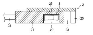
- the introduction member 2 is a substantially rectangular parallelepiped member whose longitudinal direction is the vertical direction.
- the upstream end of the introduction member 2 is connected to a charging chute into which the welding nut 3 is charged. That is, the introduction member 2 is configured such that the welding nut 3 introduced into the introduction chute passes through the inside of the introduction member 2 by free fall and is sent to the downstream side.
- the introduction member 2 includes an introduction passage 21, a notch portion 23, and an outlet portion 25.
- the introduction passage 21 is a passage through which the welding nut 3 passes. As shown in FIG. 5, the introduction passage 21 is formed from the upper end to the lower end at a position near the front of the introduction member 2.
- the introduction passage 21 has a rectangular cross section.
- the cross-sectional shape of the introduction passage 21 is formed such that the long side dimension is slightly larger than the outer diameter of the welding nut 3 and the short side dimension is slightly larger than the thickness of the welding nut 3.
- the cross section of the introduction passage 21 has a long side extending in the left-right direction and a short side extending in the front-rear direction. In this way, the introduction passage 21 is formed so that the front surface portion 3a and the back surface portion 3b of the welding nut 3 face in the front-rear direction, which is a direction orthogonal to the direction in which the welding nut 3 passes.
- the notch 23 is formed so as to be adjacent to the lower side of the introduction passage 21.
- the notch 23 is formed to be recessed from the front surface of the introduction member 2 toward the rear side, and is provided over the entire lateral direction of the introduction passage 21.
- the vertical dimension of the notch 23 is formed to be slightly larger than the outer diameter of the weld nut 3.
- a sorting member 27 constituting a part of the discrimination sorting portion 5 is fitted in the notch portion 23 .
- the configuration of the sorting member will be described later.
- the exit part 25 is formed so as to contact the lower end of the notch part 23.
- the outlet portion 25 includes a first outlet 25a and a second outlet 25b.
- the first outlet 25a and the second outlet 25b are provided adjacent to each other in the left-right direction, and the first outlet 25a is located on the left side of the second outlet 25b.
- a partition wall 37 is provided between the first outlet 25a and the second outlet 25b.
- the dimensions of the outlets 25a and 25b in the left-right direction and the front-rear direction are substantially the same as those of the introduction passage 21.
- an air nozzle that injects compressed air downward may be disposed on the inner walls of the outlets 25a and 25b in order to facilitate feeding the welding nut 3 downward.
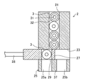
- the branch portion 4 is provided on the downstream side of the introduction passage 21.
- the branch portion 4 includes a first twist chute 41a and a first discharge passage 60a that constitute the first branch passage 40a, and a second twist chute 41b and a second discharge passage 60b that constitute the second branch passage 40b. .
- the first torsion chute 41a is connected to communicate with the first outlet 25a by the first connecting pipe portion 43a.
- the first connecting pipe portion 43a has an upper end portion inserted into the first outlet 25a and a lower end portion inserted into the first torsion chute 41a.
- the first torsion chute 41a is a flexible tube having a rectangular cross section.
- the cross-sectional shape of the first torsion chute 41 a is formed such that the dimension of the long side is slightly larger than the outer diameter of the welding nut 3 and the dimension of the short side is slightly larger than the thickness of the welding nut 3.
- the first torsion chute 41a is provided so that the long side extends in the left-right direction and the short side extends in the front-rear direction at the upper end portion.
- the first torsion chute 41a is twisted so that the lower end portion is rotated 90 ° counterclockwise as compared with the upper end portion as viewed from above, which is a cross-sectional view orthogonal to the direction in which the welding nut 3 passes. It is fixed to the discharge member 6 in a state.
- the first torsion chute 41a is provided at the lower end so that the long side extends in the front-rear direction and the short side extends in the left-right direction.
- the second torsion chute 41b is connected so as to communicate with the second outlet 25b by the second connecting pipe portion 43b.
- the second connecting pipe portion 43b has an upper end portion inserted into the second outlet 25b and a lower end portion inserted into the second torsion chute 41b.
- the second torsion chute 41b is a tube having a rectangular cross section having flexibility.
- the cross-sectional shape of the second torsion chute 41 b is formed such that the dimension of the long side is slightly larger than the outer diameter of the welding nut 3 and the dimension of the short side is slightly larger than the thickness of the welding nut 3.
- the second torsion chute 41b is provided so that the long side extends in the left-right direction and the short side extends in the front-rear direction at the upper end portion.
- the second torsion chute 41b is twisted so that the lower end portion is rotated and displaced 90 ° clockwise compared to the upper end portion as viewed from above in a cross-sectional view orthogonal to the direction in which the welding nut 3 passes. It is fixed to the discharge member 6.
- the second torsion chute 41b is twisted so as to be displaced by 90 ° in the direction opposite to the rotational displacement of the first torsion chute 41a. That is, the second torsion chute 41b is provided such that, at the lower end, the long side extends in the front-rear direction and the short side extends in the left-right direction.
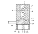
- the first discharge passage 60 a and the second discharge passage 60 b are formed in the discharge member 6.
- the discharge member 6 is provided on the downstream side of the branch portion 4 and sends the welding nut 3 to the supply head.
- the discharge member 6 includes a discharge passage 60 formed in a substantially Y shape inside.
- a first discharge passage 60a, a second discharge passage 60b, a merging passage 61, and a merging portion 63 are formed in the discharge passage 60.
- the discharge passage 60 has a rectangular cross section, and is formed such that the long side dimension is slightly larger than the outer diameter of the welding nut 3 and the short side dimension is slightly larger than the thickness of the welding nut 3.
- the cross section of the discharge passage 60 is formed such that the long side extends in the front-rear direction and the short side extends in the left-right direction.
- the first discharge passage 60a and the second discharge passage 60b are formed in parallel from the upper end portion of the discharge member 6 to the middle portion in the vertical direction.
- the first discharge passage 60a and the second discharge passage 60b are provided side by side in the front-rear direction.
- the first discharge passage 60a is located on the front side of the second discharge passage 60b.
- the lower end portion of the first torsion chute 41a is inserted into the upper end portion of the first discharge passage 60a.
- the 1st discharge passage 60a constitutes the 1st branch passage 40a with the 1st twist chute 41a.
- the first discharge passage 60a is not twisted, and allows the welding nut 3 to pass therethrough without changing the direction of the welding nut 3 sent from the first torsion chute 41a.
- the lower end of the second torsion chute 41b is inserted into the upper end of the second discharge passage 60b.
- the second discharge passage 60b constitutes a second branch passage 40b together with the second torsion chute 41b.
- the second discharge passage 60b is not twisted and allows the welding nut 3 to pass therethrough without changing the direction of the welding nut 3 sent from the second torsion chute 41b.
- the first discharge passage 60a and the second discharge passage 60b join at a joining portion 63 located in the middle in the vertical direction of the discharge member 6. That is, the first branch passage 40a and the second branch passage 40b join at the joining portion 63.
- a junction passage 61 extends on the downstream side of the junction 63 in the discharge passage 60.
- the discrimination distribution unit 5 discriminates the front side and the back side of the welding nut 3 while the welding nut 3 is stationary.
- the discrimination distribution unit 5 sends the front-facing welding nut 3 to the first torsion chute 41a, while sending the back-facing welding nut 3 to the second torsion chute 41b.
- the determination distribution unit includes a distribution member 27 and a determination member 8.
- the distribution member 27 is provided in the notch 23.
- the dimension of the outer shape of the sorting member 27 is substantially the same as that of the notch 23.
- the sorting member 27 includes a groove 29 that is recessed from the front surface toward the rear side.
- the distribution member 27 is connected to the actuator 28 and is slidable in the left-right direction.
- the groove 29 communicates with the introduction passage 21 at the same position in the left-right direction.
- the groove 29 receives the welding nut 3 that has passed through the introduction passage 21.
- the groove portion 29 holds the welding nut 3 in a state where the front surface portion 3a and the back surface portion 3b are directed in the front-rear direction. That is, the groove portion 29 functions as a holding portion that holds the welding nut 3.
- the bottom surface 35 of the groove portion 29 serves as a contact surface that contacts the surface portion 3 a or the protrusion 32 of the welding nut 3.
- the distributing member 27 distributes the welding nut 3 determined to be face-up by the determining member 8 to the first outlet 25a, and distributes the welding nut 3 determined to be face-down to the second outlet 25b. The distribution operation of the distribution member 27 will be described later.
- the discriminating member 8 is provided on the front surface of the introducing member 2. Specifically, the determination member 8 is provided on the front side of the notch 23.
- the determination member 8 includes, for example, a cylinder 80 provided with an expansion / contraction portion 81 that expands and contracts in the front-rear direction at the distal end portion, and the determination member 8 that is stationary in the groove portion 29 of the distribution member 27.
- the front side and the back side of the welding nut 3 in the state are discriminated.
- the discrimination member 8 includes a first distance from the bottom surface 35 to the surface portion 3a when the protrusion 32 of the welding nut 3 contacts the bottom surface 35, and a case where the surface portion 3a of the welding nut 3 contacts the bottom surface 35.
- the second distance from the bottom surface 35 to the back surface portion 3b is detected, and the front side and the back side of the welding nut 3 are discriminated based on the difference between the first distance and the second distance.
- the cylinder 80 includes a main body portion 83 and an expansion / contraction portion 81 that expands and contracts in the front-rear direction with respect to the main body portion 83.
- the telescopic part 81 includes an insertion part 85 and a pressing part 87.
- the insertion portion 85 constitutes the distal end portion of the stretchable portion 81.
- the insertion portion 85 is formed in a cylindrical shape.
- the outer diameter of the insertion portion 85 is smaller than the inner diameter of the screw hole 31 of the welding nut 3.
- the length dimension of the insertion portion 85 is smaller than the thickness of the welding nut 3.
- the holding portion 87 is adjacent to the insertion portion 85.
- the pressing portion 87 is formed in a cylindrical shape.
- the outer diameter of the holding portion 87 is larger than the inner diameter of the screw hole 31 of the welding nut 3 and smaller than the inner diameter of the protrusion 32.
- FIG. 8 is a schematic view showing a state of discriminating the front side and the back side of the front facing welding nut 3.
- the expansion / contraction part 81 extends rearward.
- the insertion portion 85 is inserted into the screw hole 31 when the stretchable portion 81 extends.
- the pressing portion 87 is in contact with the front surface portion 3 a of the welding nut 3 and presses the back surface of the welding nut 3 against the bottom surface 35.
- the protrusion 32 on the back surface of the welding nut 3 is in contact with the bottom surface 35, the first distance from the bottom surface 35 to the surface portion 3 a is equal to the thickness of the welding nut 3 including the height of the protrusion 32.
- FIG. 9 is a schematic view showing a state of discriminating the front side and the back side of the welding nut 3 facing down.
- the insertion portion 85 is inserted into the screw hole 31 when the stretchable portion 81 extends.
- the pressing portion 87 is in contact with the back surface portion 3 b of the welding nut 3 and presses the surface portion 3 a of the welding nut 3 against the bottom surface 35.
- the flat surface portion 3a of the welding nut 3 is in contact with the bottom surface 35, the second distance from the bottom surface 35 to the back surface portion 3b is equal to the thickness of the welding nut 3 excluding the height of the protrusion 32. .
- the determination unit determines, for example, the front side and the back side of the welding nut 3 by detecting the amount of expansion / contraction of the expansion / contraction unit 81.
- the welding nut 3 sent from the charging chute passes through the introduction passage 21 by free fall without specifying the front and back directions. That is, in the introduction passage 21, the front-facing welding nut 3 and the back-facing welding nut 3 are mixed.
- the welding nut 3 that has passed through the introduction passage 21 is held in the groove 29 of the sorting member 27. At this time, since there is a partition wall 37 below the groove portion 29, the free-falling weld nut 3 is supported by the partition wall 37 and stops.
- the cylinder 80 When the welding nut 3 is accommodated in the groove 29, the cylinder 80 is operated, and the front side and the back side of the welding nut 3 are discriminated by the above method.
- the actuator 28 slides the sorting member 27 to the left so that the left and right positions of the groove 29 and the first outlet 25a coincide. .
- the welding nut 3 is sent to the 1st exit 25a, and passes the 1st branch passage 40a by free fall. Since the first torsion chute 41a is twisted so that the lower end of the first torsion chute 41 is rotated 90 ° counterclockwise as compared to the upper end when viewed from above, the front-facing welding nut 3 has the first torsion chute 41a. Is passed, the front surface portion 3a is directed to the right side and the back surface portion 3b is directed to the left side in the first discharge passage 60a. The welding nut 3 is sent to the merging portion 63 with the front surface portion 3a facing the right side and the back surface portion 3b facing the left side.
- the actuator 28 moves the sorting member 27 to the right so that the positions of the groove 29 and the second outlet 25b in the left-right direction match. Slide. And the welding nut 3 is sent to the 2nd exit 25b, and passes the 2nd branch passage 40b by free fall. Since the second torsion chute 41b is twisted so that the lower end of the second torsion chute 41b is rotated by 90 ° clockwise as compared with the upper end when viewed from above, the reverse side welding nut 3 is provided with the second torsion chute 41b. Is passed, the front surface portion 3a is directed to the right side and the back surface portion 3b is directed to the left side in the second discharge passage 60b. The welding nut 3 is sent to the merging portion 63 with the front surface portion 3a facing the right side and the back surface portion 3b facing the left side.
- the welding nut 3 is directed in the same direction when passing through the branching portion 4.
- the welding nut 3 sent to the joining passage 61 is sent to a supply head (not shown).
- the welding nut 3 as a part is stationary and the front side and the back side of the welding nut 3 are discriminated, and the welding nut 3 discriminated to be front side is turned back to the first branch passage 40a.
- the welding nut 3 determined as follows is sequentially sent to the second branch passage 40b. For this reason, the welding nut 3 can be intermittently sent to the first branch passage 40a or the second branch passage 40b. Therefore, since the collision by the welding nuts 3 is suppressed in the junction part 63, components can be smoothly fed without providing the branch pin 4 with a stopper pin.
- the discrimination distribution unit 5 discriminates the front side and the back side of the welding nut 3 in the groove portion 29 located between the introduction passage 21 and the branching portion 4. For this reason, it is not necessary to move the welding nut 3 separately in order to discriminate between the front side and the back side of the welding nut 3.
- the first distance from the bottom surface 35 to the surface portion 3 a is a dimension corresponding to the thickness including the protrusion 32 of the welding nut 3.
- the second distance from the bottom surface 35 to the back surface portion 3 b is a dimension corresponding to the thickness excluding the protrusion 32 of the welding nut 3. Therefore, by detecting the first distance and the second distance, it is possible to determine whether the welding nut 3 is face-up or face-down while the welding nut 3 is stationary.
- first torsion chute 41a of the first branch passage 40a is screwed so that the downstream end is rotated and displaced by 90 ° compared to the upstream end in a cross-sectional view orthogonal to the direction in which the welding nut 3 passes. It has been.
- the second torsion chute 41b of the second branch passage 40b has a rotational end of the first torsion chute 41a compared to the upstream end in the cross-sectional view orthogonal to the direction in which the welding nut 3 passes. Are twisted so that they are displaced by 90 ° in the opposite direction. That is, the first torsion chute 41a and the second torsion chute 41b are twisted so that the rotational displacement amount is approximately the same.
- the difference between the time taken for the welding nut 3 to pass through the first branch passage 40a and the time taken for the welding nut 3 to pass through the second branch passage 40b can be reduced. For this reason, it can suppress that the several welding nut 3 sent intermittently to the branch part 4 is simultaneously sent to the confluence
- the welding nut 3 in which the front surface portion 3a is a flat surface and the protrusions 32 are formed on the entire outer periphery of the back surface portion 3b is described as a component, but the present invention is not limited thereto.
- the protrusions may be provided intermittently on the outer peripheral edge of the back surface of the component, or the protrusions may not be provided.
- the discriminating member 8 includes the cylinder 80, and detects a first distance from the bottom surface 35 to the surface portion 3a of the welding nut 3 and a second distance from the bottom surface 35 to the back surface portion 3b of the welding nut 3.
- determination member 8 which discriminate
- the discrimination member for example, an image sensor, an optical sensor, a sound wave sensor, a proximity sensor, or the like may be used, and various discrimination means may be mentioned.
- the lower end portion of the first torsion chute 41a is twisted so as to be rotated 90 ° counterclockwise as compared with the upper end portion when viewed from above, and the lower end portion of the second torsion chute 41b. Is twisted so as to be rotated and displaced by 90 ° in the direction opposite to the rotational displacement of the lower end portion of the first torsion chute 41a as viewed from above, but is not limited to this.
- one torsion chute may not be twisted, and the lower end portion of the other torsion chute may be twisted so as to be rotationally displaced by 180 ° compared to the upper end portion when viewed from above.
- the lower end of one torsion chute is twisted so as to be rotationally displaced at a predetermined first angle compared to the upper end as viewed from above, and the lower end of the other torsion chute is viewed from above.
- it is twisted so as to be rotationally displaced at a predetermined second angle in a direction opposite to the lower end portion of one torsion chute as compared with the upper end portion, and the sum of the first angle and the second angle is 180 °. It may be. That is, the angle at which each torsion chute is twisted is not limited.
- first branch passage 40a is constituted by the first twist chute 41a and the first discharge passage 60a
- second branch passage 40b is constituted by the second twist chute 41b and the second discharge passage 60b. It is not limited to this.
- each branch passage may be constituted by a single member.
Landscapes
- Engineering & Computer Science (AREA)
- Mechanical Engineering (AREA)
- Feeding Of Articles To Conveyors (AREA)
Priority Applications (4)
| Application Number | Priority Date | Filing Date | Title |
|---|---|---|---|
| EP19784587.8A EP3760558B1 (de) | 2018-04-11 | 2019-04-05 | Vorrichtung zum ausrichten und transportieren von teilen |
| KR1020207030260A KR102695412B1 (ko) | 2018-04-11 | 2019-04-05 | 부품 정렬 이송 장치 |
| CN201980025070.3A CN111954633A (zh) | 2018-04-11 | 2019-04-05 | 部件整列输送装置 |
| US17/064,291 US11117753B2 (en) | 2018-04-11 | 2020-10-06 | Part alignment and transport device |
Applications Claiming Priority (2)
| Application Number | Priority Date | Filing Date | Title |
|---|---|---|---|
| JP2018-076024 | 2018-04-11 | ||
| JP2018076024A JP6629380B2 (ja) | 2018-04-11 | 2018-04-11 | 部品整送装置 |
Related Child Applications (1)
| Application Number | Title | Priority Date | Filing Date |
|---|---|---|---|
| US17/064,291 Continuation US11117753B2 (en) | 2018-04-11 | 2020-10-06 | Part alignment and transport device |
Publications (1)
| Publication Number | Publication Date |
|---|---|
| WO2019198643A1 true WO2019198643A1 (ja) | 2019-10-17 |
Family
ID=68163132
Family Applications (1)
| Application Number | Title | Priority Date | Filing Date |
|---|---|---|---|
| PCT/JP2019/015174 Ceased WO2019198643A1 (ja) | 2018-04-11 | 2019-04-05 | 部品整送装置 |
Country Status (6)
| Country | Link |
|---|---|
| US (1) | US11117753B2 (de) |
| EP (1) | EP3760558B1 (de) |
| JP (1) | JP6629380B2 (de) |
| KR (1) | KR102695412B1 (de) |
| CN (1) | CN111954633A (de) |
| WO (1) | WO2019198643A1 (de) |
Families Citing this family (5)
| Publication number | Priority date | Publication date | Assignee | Title |
|---|---|---|---|---|
| CN112573148B (zh) * | 2020-11-23 | 2022-05-10 | 江苏科技大学 | 一种虎钳毛坯立体仓储装置 |
| TWI792690B (zh) * | 2021-11-17 | 2023-02-11 | 威光自動化科技股份有限公司 | 彈匣式鎖螺絲機 |
| TWI792691B (zh) * | 2021-11-17 | 2023-02-11 | 威光自動化科技股份有限公司 | 彈匣式鎖螺絲機 |
| US12515892B2 (en) * | 2022-08-17 | 2026-01-06 | Innovation Associates, Inc. | Pneumatic conveyance jet diverter |
| CN117262656A (zh) * | 2023-10-18 | 2023-12-22 | 江苏凯伦建材股份有限公司 | 一种包装袋输送的正反面纠错系统及方法 |
Citations (4)
| Publication number | Priority date | Publication date | Assignee | Title |
|---|---|---|---|---|
| JPH02193812A (ja) * | 1989-01-23 | 1990-07-31 | Kimura Denyouki Seisakusho:Kk | ナット分別装置 |
| JPH0616225A (ja) * | 1991-09-07 | 1994-01-25 | Taiyo Yuden Co Ltd | 部品表裏選別整列供給装置 |
| JPH07315554A (ja) | 1994-05-24 | 1995-12-05 | Shinjiyou Seisakusho:Kk | 部品の高速整送装置 |
| JP2013154972A (ja) * | 2012-01-27 | 2013-08-15 | Honda Motor Co Ltd | ナット供給装置及びその方法 |
Family Cites Families (15)
| Publication number | Priority date | Publication date | Assignee | Title |
|---|---|---|---|---|
| US3221857A (en) * | 1964-07-09 | 1965-12-07 | Holstein & Kappert Maschf | Apparatus for orienting bottle caps and the like |
| US3823803A (en) * | 1972-12-26 | 1974-07-16 | Multifastener Corp | Nut transfer and orienting device |
| JPS58919B2 (ja) * | 1973-09-14 | 1983-01-08 | マツナカ シゲオ | ヒヨウリヒタイシヨウブツピン ノ ヒヨウリケンシユツソウチ |
| US3908859A (en) * | 1974-01-31 | 1975-09-30 | S J Agnew Agnew Environmental | Article dispensing apparatus |
| US4033441A (en) * | 1975-06-16 | 1977-07-05 | Aluminum Company Of America | Merging or blending techniques for small parts |
| JPS552878U (de) * | 1979-04-23 | 1980-01-10 | ||
| US4265356A (en) * | 1979-08-20 | 1981-05-05 | The Lodge & Shipley Company | Apparatus for combining articles from plural lanes into a single lane |
| US5394973A (en) * | 1994-06-06 | 1995-03-07 | Micron Technology, Inc. | Sorter for integrated circuit devices |
| JP4185635B2 (ja) * | 1999-09-24 | 2008-11-26 | セキ工業株式会社 | ナット抵抗溶接用ナット供給装置 |
| US7559435B2 (en) * | 2003-09-16 | 2009-07-14 | Seki Kogyo Co., Ltd. | Nut feeder |
| JP4315989B2 (ja) * | 2007-04-03 | 2009-08-19 | セキ工業株式会社 | ナット供給方法及びナット供給装置 |
| CN104003157B (zh) * | 2014-05-22 | 2016-03-23 | 杭州中亚机械股份有限公司 | 一种翻转输送装置 |
| CN104828760B (zh) * | 2015-04-30 | 2018-01-09 | 泉州华硕实业有限公司 | 一种自动上底盖机 |
| CN206871926U (zh) * | 2017-05-26 | 2018-01-12 | 海宁上通优必胜轴承有限公司 | 一种用于轴承套圈的送料装置 |
| EP3498639B1 (de) * | 2017-12-14 | 2020-05-20 | BEUMER Group GmbH & Co. KG | Vorrichtung zum zusammenführen von zwei in unterschiedlichen höhen angeordneten stückgutströmen |
-
2018
- 2018-04-11 JP JP2018076024A patent/JP6629380B2/ja active Active
-
2019
- 2019-04-05 EP EP19784587.8A patent/EP3760558B1/de active Active
- 2019-04-05 KR KR1020207030260A patent/KR102695412B1/ko active Active
- 2019-04-05 WO PCT/JP2019/015174 patent/WO2019198643A1/ja not_active Ceased
- 2019-04-05 CN CN201980025070.3A patent/CN111954633A/zh active Pending
-
2020
- 2020-10-06 US US17/064,291 patent/US11117753B2/en active Active
Patent Citations (4)
| Publication number | Priority date | Publication date | Assignee | Title |
|---|---|---|---|---|
| JPH02193812A (ja) * | 1989-01-23 | 1990-07-31 | Kimura Denyouki Seisakusho:Kk | ナット分別装置 |
| JPH0616225A (ja) * | 1991-09-07 | 1994-01-25 | Taiyo Yuden Co Ltd | 部品表裏選別整列供給装置 |
| JPH07315554A (ja) | 1994-05-24 | 1995-12-05 | Shinjiyou Seisakusho:Kk | 部品の高速整送装置 |
| JP2013154972A (ja) * | 2012-01-27 | 2013-08-15 | Honda Motor Co Ltd | ナット供給装置及びその方法 |
Non-Patent Citations (1)
| Title |
|---|
| See also references of EP3760558A4 |
Also Published As
| Publication number | Publication date |
|---|---|
| US20210016403A1 (en) | 2021-01-21 |
| KR102695412B1 (ko) | 2024-08-16 |
| JP6629380B2 (ja) | 2020-01-15 |
| EP3760558A4 (de) | 2021-04-28 |
| JP2019182608A (ja) | 2019-10-24 |
| CN111954633A (zh) | 2020-11-17 |
| EP3760558B1 (de) | 2023-07-19 |
| KR20200141460A (ko) | 2020-12-18 |
| EP3760558A1 (de) | 2021-01-06 |
| US11117753B2 (en) | 2021-09-14 |
Similar Documents
| Publication | Publication Date | Title |
|---|---|---|
| WO2019198643A1 (ja) | 部品整送装置 | |
| US10543558B2 (en) | Welding diffuser insert | |
| JP5571745B2 (ja) | 二重ワイヤ溶接トーチおよびそれに関連する方法 | |
| KR101989625B1 (ko) | 워크 정렬 반송 장치 | |
| JP2020058995A (ja) | シール材吐出ノズルおよびシール材吐出装置 | |
| US20140263250A1 (en) | Welding diffuser with debris removal | |
| US10688586B2 (en) | Welding torch | |
| US10500670B2 (en) | Flexible wire guide system | |
| JP2010001124A (ja) | 供給装置 | |
| JP2008273688A (ja) | ナットフィーダ | |
| JP6706008B2 (ja) | 粉体供給装置 | |
| CN103770014B (zh) | 湿式喷砂用喷枪 | |
| JP2018043269A (ja) | 電極部構造及びそれを用いた抵抗溶接機 | |
| JP2020058994A (ja) | シール材吐出ノズルおよびシール材吐出装置 | |
| JP2017113777A (ja) | スタッド溶接機におけるスタッドの保留、排出装置 | |
| JP5168622B2 (ja) | 部品供給装置 | |
| JP5224170B2 (ja) | 部品供給装置 | |
| JP2010024050A (ja) | フランジ付き部品の供給制御装置および通路構造 | |
| KR20210063802A (ko) | 쉴드 가스를 이용한 로봇용접용 와이어 브레이크 장치 | |
| JP2000136019A (ja) | 振動式複数列部品供給装置 | |
| JP2009148722A (ja) | 気中キャビテーションジェットノズル | |
| JP2006168988A (ja) | プロジェクションナット用パーツフィーダおよび分離方法 | |
| KR20240134822A (ko) | 3d 프린터의 모듈형 분사장치 | |
| JP6898559B2 (ja) | エアノズル、及びこれを備えたパーツフィーダ | |
| JP2026052359A (ja) | レーザ加工装置 |
Legal Events
| Date | Code | Title | Description |
|---|---|---|---|
| 121 | Ep: the epo has been informed by wipo that ep was designated in this application |
Ref document number: 19784587 Country of ref document: EP Kind code of ref document: A1 |
|
| ENP | Entry into the national phase |
Ref document number: 2019784587 Country of ref document: EP Effective date: 20200930 |
|
| NENP | Non-entry into the national phase |
Ref country code: DE |
|
| ENP | Entry into the national phase |
Ref document number: 20207030260 Country of ref document: KR Kind code of ref document: A |