WO2019203043A1 - ラジアスエンドミル及びこれを用いた工作機械、並びにラジアスエンドミルの設計方法及び加工方法 - Google Patents
ラジアスエンドミル及びこれを用いた工作機械、並びにラジアスエンドミルの設計方法及び加工方法 Download PDFInfo
- Publication number
- WO2019203043A1 WO2019203043A1 PCT/JP2019/015289 JP2019015289W WO2019203043A1 WO 2019203043 A1 WO2019203043 A1 WO 2019203043A1 JP 2019015289 W JP2019015289 W JP 2019015289W WO 2019203043 A1 WO2019203043 A1 WO 2019203043A1
- Authority
- WO
- WIPO (PCT)
- Prior art keywords
- end mill
- radius end
- blade
- central axis
- radius
- Prior art date
- Legal status (The legal status is an assumption and is not a legal conclusion. Google has not performed a legal analysis and makes no representation as to the accuracy of the status listed.)
- Ceased
Links
Images


Classifications
-
- B—PERFORMING OPERATIONS; TRANSPORTING
- B23—MACHINE TOOLS; METAL-WORKING NOT OTHERWISE PROVIDED FOR
- B23C—MILLING
- B23C5/00—Milling-cutters
- B23C5/02—Milling-cutters characterised by the shape of the cutter
- B23C5/10—Shank-type cutters, i.e. with an integral shaft
-
- B—PERFORMING OPERATIONS; TRANSPORTING
- B23—MACHINE TOOLS; METAL-WORKING NOT OTHERWISE PROVIDED FOR
- B23C—MILLING
- B23C2210/00—Details of milling cutters
- B23C2210/08—Side or top views of the cutting edge
- B23C2210/082—Details of the corner region between axial and radial cutting edges
-
- B—PERFORMING OPERATIONS; TRANSPORTING
- B23—MACHINE TOOLS; METAL-WORKING NOT OTHERWISE PROVIDED FOR
- B23C—MILLING
- B23C2210/00—Details of milling cutters
- B23C2210/08—Side or top views of the cutting edge
- B23C2210/084—Curved cutting edges
Definitions
- the present invention relates to a radius end mill, a machine tool using the same, and a design method and a processing method of the radius end mill.
- connecting member manufactured by machining from the viewpoint of weight reduction and high accuracy is used for a connecting member or the like (hereinafter simply referred to as “connecting member”) of a body panel and a frame, which has been conventionally formed of sheet metal. I'm starting. However, since machining generally increases material costs, it is necessary to reduce machining costs.
- Processing time needs to be reduced to reduce processing costs. For that purpose, it is necessary to increase the feed rate and the cutting amount.
- the surface roughness Rz [mm] is expressed by the following equation using a feed amount fz [mm / tooth] per blade and a nose R [mm] which is the radius of the arcuate blade at the blade edge.
- Rz fz2 / (8 ⁇ R) (1)
- a radius end mill having an arc blade at the cutting edge of the tool is frequently used.
- Square end mills that do not have an arc blade generate cutting force mainly in the feed direction, but radius end mills have an arc shape, so cutting force is also generated in the tool center axis direction, and cutting force is generated in the plate thickness direction.
- a radius end mill tends to generate chatter vibration in a workpiece having a thin plate portion.
- the occurrence of chatter vibration is inevitable. Therefore, although it is necessary to increase the nose R as shown in the formula (1), there is a problem that the nose R has to be reduced from the viewpoint of stability against chatter vibration.
- Measures for such chatter vibration include those disclosed in Patent Documents 1 and 2.
- Patent Document 1 providing the outer periphery blade connected to a circular arc blade is disclosed.
- Patent Document 2 it is disclosed that the pitch between adjacent spiral grooves is varied.
- Non-Patent Document 1 regenerative self-excited chatter vibration has been reported as chatter vibration (Non-Patent Document 1).
- chatter vibration the vibration generated when cutting one blade before remains as the undulation of the processed surface, and the vibration is regenerated as a change in the cut thickness in the current cutting. For this reason, a closed loop is formed in which the cutting force fluctuates and vibration is generated again, and the vibration grows under a predetermined condition to generate large chatter vibration.
- the reproduction width varies depending on the size and shape of the arc blade provided on the tooth end of the radius end mill.
- the reproduction width is a dimension that causes regenerative self-excited chatter vibration, and means a dimension in a cutting direction in which one blade cuts, that is, a dimension in a cutting direction in which an arcuate blade and a workpiece come into contact with each other.
- the larger the reproduction width the greater the influence of vibration at the time of reproduction one blade before, so that chatter vibration is more likely to occur and processing stability is lowered.
- the present invention has been made in view of such circumstances, and the present invention provides a radius end mill capable of suppressing chatter vibration and improving machining stability, a machine tool using the same, a design method of the radius end mill, and An object is to provide a processing method.
- a radius end mill includes an arc blade provided on an outer peripheral side of a tip portion of a tool body, and an angle range in which the arc blade is formed in a longitudinal section including a central axis of the tool body is 30 degrees or less.
- the playback width is 1 ⁇ 2 or less compared to the case where the angle range is 90 °, and chatter vibration is suppressed and machining is stable. Can be improved.
- the lower limit value of the angle range is, for example, 0.09 °.
- the radius (nose R) forming the arc shape of the arc blade is, for example, 1 mm or more and 1000 mm or less.
- the circular arc blade has a bottom surface extending from a position having a tangent to a side surface at least in a direction orthogonal to the central axis at the bottom surface of the tip of the tool body in the longitudinal section. It is formed as a circular arc blade for use, and the dimension of the bottom circular arc blade in the central axis direction is 0.75 mm or less.
- a radius end mill for bottom processing is provided.
- the dimension (nose R height Hr) in the central axis direction of the tool body of the arc blade in the longitudinal section is 0.75 mm or less, the reproduction width is reduced to 1 / compared to the case where the angle range of the arc blade is 90 °.
- the chatter vibration can be suppressed as 2 or less, and the processing stability can be improved.
- the lower limit value of the nose R height Hr is, for example, 0.03 mm.
- the arcuate blade is formed from the position having a tangent to a side surface of the tip portion of the tool body in a direction parallel to the central axis in the longitudinal section. Is formed as a circular arc blade for a side surface, and a dimension in a direction perpendicular to the central axis direction of the circular arc blade for the side surface is set to 0.75 mm or less.
- a radial end mill for side processing is provided by forming an arcuate blade from a position having a tangent in a direction parallel to the central axis of the tool body on the side surface of the tip of the tool body in the longitudinal section to the bottom surface of the tip. .
- Reproduced in comparison with the arc blade angle range of 90 ° by making the dimension (nose R height Hr) in the direction perpendicular to the central axis direction of the tool body of the arc blade in the longitudinal section 0.75 mm or less.
- the lower limit value of the nose R height Hr is, for example, 0.03 mm.
- the circular arc blade has a bottom surface extending from a position having a tangent to a side surface at least in a direction orthogonal to the central axis at the bottom surface of the tip of the tool body in the longitudinal section.
- the arcuate blade for the bottom surface has a dimension in the central axis direction of the arcuate blade for the bottom surface of 0.75 mm or less, and the arcuate blade is formed on the side surface of the tip portion of the tool body in the longitudinal section.
- the side arc blade is formed from the position having a tangent line parallel to the central axis to the bottom surface of the tip, and the dimension of the side arc blade in the direction orthogonal to the central axis direction is 0.75 mm or less. ing.
- a bottom circular arc blade is formed from a position having a tangent to a side surface in a direction perpendicular to the center axis of the tool main body at the bottom surface of the tip of the tool main body in a vertical cross section, and the side circular arc blade is formed in the vertical cross section of the tool main body.
- a radius end mill for hybrid machining capable of bottom machining and side machining is provided by forming from the position having a tangent parallel to the central axis of the tool body on the side of the tip to the tip.
- the playback width can be reduced to 1 ⁇ 2 or less to suppress chatter vibration and improve the processing stability.
- a machine tool the radius end mill according to any one of the above, a drive unit that is fixed to the base end portion of the radius end mill and rotates around the central axis of the radius end mill,
- the radius of the arc forming the arc shape of the arc blade of the radius end mill includes a feed amount per blade calculated from the rotational speed of the drive unit and a cutting feed speed, and a required surface required during machining. It is determined based on the roughness.
- the feed amount per tooth is calculated from the rotational speed of the drive unit and the cutting feed speed. Based on the feed amount per blade and the required surface roughness required during processing (for example, the surface roughness required in the drawing), the radius of the radius end mill's arc blade is determined. As a result, chatter vibration is suppressed and stable machining can be performed under any cutting condition that satisfies the required surface roughness. If the radius of the arcuate blade is determined using the maximum rotational speed of the drive unit and the cutting feed speed, the processing speed can be maximized.
- a radius end mill design method is a radius end mill design method for designing the radius end mill according to any one of the above, wherein the rotational speed of a drive unit that rotates the radius end mill around the central axis.
- the radius of the arc that forms the arc shape of the arc blade of the radius end mill is determined based on the feed amount per blade calculated from the cutting feed speed and the required surface roughness required during machining.
- the feed amount per tooth is calculated from the rotational speed of the drive unit and the cutting feed speed. Based on the feed amount per blade and the required surface roughness required during processing (for example, the surface roughness required in the drawing), the radius of the radius end mill's arc blade is determined. Thereby, the process which suppressed chatter vibration on the arbitrary cutting conditions which satisfy
- the processing method which concerns on 1 aspect of this invention is a processing method processed using the radius end mill in any one of said, Comprising: The workpiece fixing process which fixes the workpiece
- chatter vibration is suppressed because the radius end mill is used. Further, chatter vibration can be suppressed even if machining is performed from different directions while the workpiece is fixed, so that one-chuck machining is possible and machining can be performed with high efficiency.
- “Working from different directions with respect to the workpiece” means, for example, that machining is performed in a direction perpendicular to the center axis of the tool body in the case of bottom machining, and the center of the tool body in the case of side machining. Processing is performed in a direction parallel to the axis.
- the vertical direction and the parallel direction are allowed to tilt within the angle range of the arc blade.
- FIG. 1 is a side view of a radius end mill according to a first embodiment of the present invention. It is the enlarged view which showed the detail of the A section of FIG. It is the graph which showed nose R height Hr with respect to nose R. It is the graph which showed nose R angle (theta) r. It is a side view of the radius end mill which concerns on 2nd Embodiment of this invention.
- FIG. 6 is an enlarged view showing details of an A ′ portion in FIG. 5. It is a side view of the radius end mill which concerns on 3rd Embodiment of this invention.
- FIG. 8 is an enlarged view showing details of a portion A ′′ in FIG. 7.
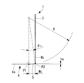
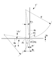
- FIG. 1 shows a radius end mill 1 according to the present embodiment.
- the radius end mill 1 is rotated about the central axis L1 by fixing the shank portion of the tool body 3 to the spindle (drive portion) of the machine tool.
- the diameter (tool diameter) of the radius end mill 1 is 4 mm or more and 32 mm or less in the case of an integrated end mill.
- the upper limit of the tool diameter is 200 mm or more.
- An arcuate blade 5 is provided on the outer peripheral side of the bottom surface of the tip 4 of the tool body 3 of the radius end mill 1.
- the radius of the arc forming the arc blade 5 is referred to as a nose R [mm].
- the radius end mill 1 shown in FIG. 1 is used for bottom processing that cuts in the tool radial direction.
- a flank 6 that is concave as compared with the tool body 3 side is formed on the inner peripheral side (center axis L1 side) of the circular arc blade 5.
- a base end 7 which is an end opposite to the tip 4 of the radius end mill 1 is a shank and is fixed to a chuck of a spindle (drive unit) of a machine tool.
- FIG. 2 shows details of part A of FIG.
- the arcuate blade 5 has a tangent in a direction perpendicular to the central axis L1 (horizontal direction in the figure) on the bottom surface 4a of the tip 4 of the tool body 3 in a longitudinal section including the central axis L1 (see FIG. 1). It is formed as a circular arc blade for the bottom surface from P1 to a position P2 intersecting with the side surface 4b.
- the arcuate blade 5 may be provided so as to extend from the position P1 toward the central axis L1. Thereby, it can connect smoothly to the bottom blade provided in the central axis L1 side.
- the nose R height Hr which is the dimension of the arcuate blade 5 in the direction of the central axis L1 (vertical direction in the figure), is 0.75 mm or less.
- the nose R which is the radius of the arc forming the arc blade 5, is set to 1 mm or more and 1000 mm or less.
- a nose R angle ⁇ r which is an angle range in which the arc blade 5 is formed, is set to 30 ° or less.
- the dimension in the direction perpendicular to the central axis L1 of the arcuate blade 5 is the reproduction width Wc.
- the reproduction width Wc is a dimension that causes regenerative self-excited chatter vibration, and is a dimension in a cutting direction in which one blade cuts, that is, a dimension in a cutting direction (horizontal direction in FIG. 2) in which the arc blade 5 and the workpiece are in contact with each other. Means. The larger the reproduction width Wc, the greater the influence of vibration during reproduction one blade ahead.
- the reproduction width Wc is expressed by the following equation using Equation (2).
- a comparative reproduction width Wc0 to be compared is determined as follows.
- Wc0 R ⁇ sin [cos-1 ((R-Ad) / R)] (4)
- Ad is the cutting amount in the direction of the central axis L1. That is, the comparative reproduction width Wc0 shown in the equation (4) means that the nose radius height is set to the cutting amount Ad.
- Ad R (that is, the nose R angle has an upper limit of 90 °).
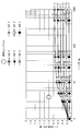
- the table below shows a case where the nose R height Hr of this embodiment is arranged so that the cut amount Ad is changed and Wc0 / Wc is 2 or more.
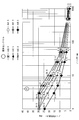
- the above Table 2 is represented in a graph as shown in FIG.
- the numerical value of the radius end mill which made the nose R height Hr smaller than the nose R for the existing bottom finishing is plotted as a reference.
- the cutting depth Ad is 3.0 mm or less and the nose R is 1 mm or more and 1000 mm or less in consideration of the maximum cutting assumed in rough machining
- the following range of the nose R height Hr is shown. If so, the stability more than twice that of the comparative example can be obtained. Nose R height Hr ⁇ 0.75mm (5)
- the table below shows a case where the nose R angle ⁇ r of this embodiment is arranged so that the cut amount Ad is changed and Wc0 / Wc is 2 or more.
- the above Table 3 is represented in a graph as shown in FIG.
- the numerical values of the radius end mill in which the nose R height Hr is smaller than the nose R are plotted for the existing bottom surface finishing shown in FIG.
- the cutting depth Ad is 3.0 mm or less and the nose R is 1 mm or more and 1000 mm or less in consideration of the maximum cutting assumed in rough machining
- the following range of nose R angles ⁇ r is satisfied. If it exists, the stability of 2 times or more is obtained with respect to the comparative example. 0 ° ⁇ Nose R angle ⁇ r ⁇ 30 ° (6)
- the nose R height Hr at this time is R ⁇ (1-31 / 2/2).
- the nose R is determined based on the feed amount per blade and the required surface roughness required at the time of processing, specifically, on the drawing.
- the surface roughness Rz is expressed by the following formula.
- Rz fz2 / (8 ⁇ R) (8)
- the nose R is expressed by the following equation using the surface roughness Rz and the feed amount fz per blade.
- R A ⁇ fz2 / (8 ⁇ Rz) (9)
- A is a coefficient in consideration of actual machining, and is, for example, 2 or more and 4 or less.
- the nose R is determined by the feed amount fz per tooth determined by the cutting feed speed F and the spindle speed S of the machine tool, and the required surface roughness.
- the workpiece to be processed has a shape formed by sheet metal processing, and has a thin plate portion such as a connecting member that connects an aircraft fuselage panel and a frame, for example.
- the workpiece before cutting is fixed to the workpiece fixing portion of the machine tool (work fixing step).
- the base end part 7 (refer FIG. 1) of the radius end mill 1 is fixed to the spindle of a machine tool. By rotating the spindle, the radius end mill 1 is rotated around the central axis L1 to cut the workpiece (machining process).
- the radius end mill 1 of the present embodiment is for bottom surface machining
- the radius end mill 1 is cut at a cutting amount Ad in the direction of the central axis L1
- the radius end mill 1 is fed to the workpiece at a cutting feed speed F in a direction orthogonal to the central axis L1.
- the machine tool is controlled by multiple axes (for example, 5 axes or 6 axes), and the radius end mill 1 is machined from different angles with respect to the workpiece during machining. That is, machining is performed on a plurality of surfaces of a workpiece by one setup (one chuck).
- the following operational effects are obtained. Reducing the nose R angle ⁇ r of the arcuate blade 5 of the radius end mill 1 for bottom machining to 30 ° or less compared to the case where the angle range of the arcuate blade is 90 ° as in the comparative example (see Table 1). By reducing the width to 1/2 or less, chatter vibration can be suppressed and the processing stability can be improved.
- the playback width can be reduced to 1 ⁇ 2 or less to suppress chatter vibration and improve the processing stability.
- the feed amount fz per blade is calculated from the spindle speed S and the cutting feed speed F of the spindle of the machine tool. Based on the feed amount fz per blade and the required surface roughness Rz required at the time of machining, the nose R that is the radius of the arcuate blade 5 of the radius end mill 1 is determined. As a result, chatter vibration is suppressed and stable machining can be performed under any cutting condition that satisfies the required surface roughness.
- chatter vibration can be suppressed even if machining is performed from different directions while the workpiece is fixed, so that one-chuck machining is possible and machining can be performed with high efficiency.
- machining from different directions while the workpiece is fixed means that machining is performed in a direction perpendicular to the central axis L1 of the tool body 3 in the case of bottom machining, and in the case of side machining. Processing is performed in a direction parallel to the central axis L1 of the tool body 3.
- the vertical direction and the parallel direction are allowed to tilt within the angle range of the arcuate blade 5.
- the table below shows the specifications of the endless mill according to the present example and the specifications of the machine tool that performs processing using the endless mill.
- the tool diameter is 20 mm.
- the specifications of the existing radius end mill are shown in the table below.
- Table 5 is a radius end mill used for roughing
- Table 6 is a radius end mill used for finishing.
- the tool diameter is 20 mm.
- the R-part contact angle ⁇ means the contact angle between the nose R and the workpiece.
- nose R angle R portion contact angle.
- the regeneration width of this example is 7 times roughing and 3 times finish finishing compared to the regeneration width of the existing radius end mill. It can be seen that chatter vibration can be greatly reduced. Further, when the joint member was actually processed, chatter vibration was generated in the existing radius end mill, but chatter vibration was not generated even in the case of processing under the same conditions in the radius end mill of this example.
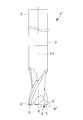
- FIG. 5 shows a radius end mill 1 ′ according to the present embodiment.
- An arcuate blade 5 ' is provided on the side surface 4b of the tip 4 of the tool body 3 of the radius end mill 1'.
- the radius end mill 1 shown in FIG. 1 is used for side surface machining by cutting in the direction of the central axis L1 of the tool body 3.
- FIG. 6 shows details of the portion A ′ in FIG.
- the arcuate blade 5 ' has a bottom surface 4a from a position P3 having a tangent in a direction parallel to the center axis L1 (vertical direction in the figure) on the side surface 4b of the tip 4 of the tool body 3 in a longitudinal section including the center axis L1. It is formed as a circular arc blade for the side surface from the position P4 that intersects with.
- a nose R height Hr ′ which is a dimension in a direction orthogonal to the central axis L1 of the arcuate blade 5 ′ (horizontal direction in the figure), is 0.75 mm or less.
- the nose R ′ which is the radius of the arc that forms the arc blade 5 ′, is 1 mm or more and 1000 mm or less.
- a nose R angle ⁇ r ′ which is an angle range in which the arcuate blade 5 ′ is formed, is greater than 0 ° and 30 ° or less.
- the playback width Wc ′ is set to 1 ⁇ 2 or less as in the first embodiment, compared to the comparative example in which the playback width Wc0 is taken in accordance with the dimension corresponding to the cutting depth. can do. Therefore, other functions and effects are the same as in the first embodiment.
- the present embodiment is a hybrid radius end mill 1 ′′ that combines the arc blade 5 of the first embodiment for bottom surface processing and the arc blade 5 ′ of the second embodiment for side processing.
- FIG. 7 shows a radius end mill 1 ′′ according to this embodiment.
- An arc blade 5 is provided on the bottom surface 4a of the tip 4 of the tool body 3 of the radius end mill 1 ′′, and an arc blade is provided on the side surface 4b. 5 'is provided.
- the radius end mill 1 shown in the figure is capable of bottom processing using the arc blade 5 and side processing using the arc blade 5 '.
- FIG. 8 shows details of the portion A ′′ in FIG.
- the arcuate blade 5 has a side surface 4b from a position P1 having a tangent in a direction (horizontal direction in the figure) perpendicular to the center axis L1 on the bottom surface 4a of the tip 4 of the tool body 3 in a longitudinal section including the center axis L1. It is formed as a circular arc blade for the bottom surface from the intersecting position P2.
- the nose R height Hr which is the dimension of the arcuate blade 5 in the direction of the central axis L1 (vertical direction in the figure), is 0.75 mm or less.
- the nose R which is the radius of the arc forming the arc blade 5, is set to 1 mm or more and 1000 mm or less.
- the nose R angle ⁇ r which is the angle range in which the arcuate blade 5 is formed, is greater than 0 ° and 30 ° or less.
- the arcuate blade 5 ' has a bottom surface 4a from a position P3 having a tangent in a direction parallel to the center axis L1 (vertical direction in the figure) on the side surface 4b of the tip 4 of the tool body 3 in a longitudinal section including the center axis L1. It is formed as a circular arc blade for the side surface over a position P4 (the same position as the position P2) intersecting with.
- a nose R height Hr ′ which is a dimension in a direction orthogonal to the central axis L1 of the arcuate blade 5 ′ (horizontal direction in the figure), is 0.75 mm or less.
- the nose R ′ which is the radius of the arc that forms the arc blade 5 ′, is 1 mm or more and 1000 mm or less.
- a nose R angle ⁇ r ′ which is an angle range in which the arcuate blade 5 ′ is formed, is greater than 0 ° and 30 ° or less.
- the reproduction width Wc ′ is R ′ ⁇ sin ⁇ r + Hr ′.
- the reproduction width Wc ′ is 1 ⁇ 2 or less as in the first embodiment and the second embodiment, compared to the comparative example in which the reproduction width Wc0 is taken in accordance with the dimension corresponding to the cut amount. Chatter vibration can be suppressed. Therefore, other functions and effects are the same as those in the first embodiment and the second embodiment.
Landscapes
- Engineering & Computer Science (AREA)
- Mechanical Engineering (AREA)
- Milling Processes (AREA)
- Turning (AREA)
Abstract
びびり振動を抑制して加工安定性を向上させることができるラジアスエンドミルを提供する。ラジアスエンドミル(1)は、工具本体(3)の先端部(4)の外周側に設けられた円弧刃(5)を備え、工具本体(3)の中心軸線を含む縦断面において、円弧刃(5)が形成された角度範囲であるノーズ(R)角度(θr)は、30°以下とされている。円弧刃(5)は、縦断面において、工具本体(3)の先端部(4)の底面(4a)にて中心軸線に直交する方向に接線を有する位置(P1)から側面(4b)にかけて底面用円弧刃として形成されている。円弧刃(5)の中心軸線方向の寸法であるノーズ(R)高さ(Hr)は、0.75mm以下とされている。
Description
本発明は、ラジアスエンドミル及びこれを用いた工作機械、並びにラジアスエンドミルの設計方法及び加工方法に関するものである。
例えば航空機に用いられる構造部品では、高精度化や軽量化の観点から薄肉化が進んでいる。例えば、従来では板金成形とされていた胴体パネルとフレームとの結合部材等(以下、単に「結合部材」という。)は、軽量化高精度化の観点から機械加工によって製作する結合部材が用いられ始めている。しかし、機械加工は、一般に素材費が増加するので、加工費の削減が必要になる。
加工費削減のためには、加工時間を低減する必要がある。そのためには、送り速度や切り込み量を増大させる必要がある。しかし、板金成形とされる部品と同じ形状に部品を機械加工する場合、素材厚さが薄いため切り込み量を増大させるには限界がある。そこで、送り速度を増大させることが重要となる。
送り速度を増大する際の注意点として面粗度がある。面粗度Rz[mm]は、一刃あたりの送り量fz[mm/tooth]と、刃先の円弧刃の半径であるノーズR[mm]を用いて下式で表される。
Rz=fz2/(8×R) ・・・(1)
式(1)から分かるように、一刃当たりの送り量fzを向上させるにはノーズRを大きくする必要がある。
Rz=fz2/(8×R) ・・・(1)
式(1)から分かるように、一刃当たりの送り量fzを向上させるにはノーズRを大きくする必要がある。
一方、例えば航空機部品の機械加工では、工具の刃先に円弧刃を有するラジアスエンドミルが多用される。円弧刃を有しないスクエアエンドミルは主に送り方向に切削力が発生するが、ラジアスエンドミルは、円弧形状があるので、工具中心軸線方向にも切削力が発生し、切削力が板厚方向に発生する場合がある。このため、ラジアスエンドミルは、薄板部を有するワークにびびり振動が発生しやすくなる。特に、ワークの固定を1回として加工するワンチャック加工では、ワークの薄板部の板厚方向に切削力が発生する加工も行うため、びびり振動の発生が避けられない。したがって、式(1)で示したようにノーズRを大きくする必要があるにも関わらず、びびり振動に対する安定性の観点からノーズRを小さくせざるを得ないという問題がある。
このようなびびり振動の対策として、特許文献1及び2に開示されたものがある。特許文献1では、円弧刃に接続される外周刃を設けることが開示されている。特許文献2では、隣接する螺旋溝間のピッチを異ならせることが開示されている。
また、びびり振動として、再生型自励びびり振動が報告されている(非特許文献1)。再生型自励びびり振動は、一刃前に切削する際に生じていた振動が加工面の起伏として残り、その振動が現在の切削において切り取り厚さの変更として再生するものである。このため、切削力が変動して再び振動が発生する閉ループが構成され、所定の条件で振動が成長して大きなびびり振動が発生する。
社本英二、"切削加工におけるびびり振動の発生機構と抑制"、電気精鋼、82巻2号(2011年)、143頁-155頁
上記の特許文献1及び2では、再生型自励びびり振動に対する検討がなされていないので、びびり振動の低減としては十分ではない。
本発明者等は、鋭意検討し、ラジアスエンドミルの歯先に設けた円弧刃の大きさや形状によって再生幅が変化することに着目した。ここで、再生幅とは、再生型自励びびり振動の起因となる寸法であり、一刃が切削する切削方向の寸法、すなわち円弧刃とワークとが接触する切削方向の寸法を意味する。再生幅が大きいほど、一刃前の再生時の振動の影響が大きくなるため、びびり振動が発生しやすくなり加工安定性が低くなる。
このような事情に鑑みてなされたものであって、本発明は、びびり振動を抑制して加工安定性を向上させることができるラジアスエンドミル及びこれを用いた工作機械、並びにラジアスエンドミルの設計方法及び加工方法を提供することを目的とする。
本発明の一態様に係るラジアスエンドミルは、工具本体の先端部の外周側に設けられた円弧刃を備え、前記工具本体の中心軸線を含む縦断面において、前記円弧刃が形成された角度範囲は、30°以下とされている。
円弧刃が形成された角度範囲(ノーズR角度θr)を30°以下とすることで、角度範囲を90°とした場合に比べて再生幅を1/2以下としてびびり振動を抑制して加工安定性を向上させることができる。
角度範囲の下限値としては、例えば0.09°とされる。円弧刃の円弧形状を形成する半径(ノーズR)は、例えば1mm以上1000mm以下とされる。
角度範囲の下限値としては、例えば0.09°とされる。円弧刃の円弧形状を形成する半径(ノーズR)は、例えば1mm以上1000mm以下とされる。
さらに、本発明の一態様に係るラジアスエンドミルでは、前記円弧刃は、前記縦断面において、前記工具本体の先端部の底面にて少なくとも前記中心軸線に直交する方向に接線を有する位置から側面にかけて底面用円弧刃として形成され、該底面用円弧刃の前記中心軸線方向の寸法は、0.75mm以下とされている。
円弧刃を縦断面において工具本体の先端部の底面にて工具本体の中心軸線に直交する方向に接線を有する位置から側面にかけて形成することで、底面加工用のラジアスエンドミルが提供される。縦断面における円弧刃の工具本体の中心軸線方向における寸法(ノーズR高さHr)を0.75mm以下とすることで、円弧刃の角度範囲を90°とした場合に比べて再生幅を1/2以下としてびびり振動を抑制して加工安定性を向上させることができる。
ノーズR高さHrの下限値としては、例えば0.03mmとされる。
ノーズR高さHrの下限値としては、例えば0.03mmとされる。
さらに、本発明の一態様に係るラジアスエンドミルでは、前記円弧刃は、前記縦断面において、前記工具本体の前記先端部の側面にて前記中心軸線に平行な方向に接線を有する位置から前記先端部の底面にかけて側面用円弧刃として形成され、該側面用円弧刃の前記中心軸線方向に直交する方向の寸法は、0.75mm以下とされている。
円弧刃を縦断面において工具本体の先端部の側面にて工具本体の中心軸線に平行な方向に接線を有する位置から先端部の底面にかけて形成することで、側面加工用のラジアスエンドミルが提供される。縦断面における円弧刃の工具本体の中心軸線方向に直交する方向おける寸法(ノーズR高さHr)を0.75mm以下とすることで、円弧刃の角度範囲を90°とした場合に比べて再生幅を1/2以下としてびびり振動を抑制して加工安定性を向上させることができる。
ノーズR高さHrの下限値としては、例えば0.03mmとされる。
ノーズR高さHrの下限値としては、例えば0.03mmとされる。
さらに、本発明の一態様に係るラジアスエンドミルでは、前記円弧刃は、前記縦断面において、前記工具本体の先端部の底面にて少なくとも前記中心軸線に直交する方向に接線を有する位置から側面にかけて底面用円弧刃として形成され、該底面用円弧刃の前記中心軸線方向の寸法は、0.75mm以下とされ、かつ、記円弧刃は、前記縦断面において、前記工具本体の前記先端部の側面にて前記中心軸線に平行に接線を有する位置から前記先端部の底面にかけて側面用円弧刃として形成され、該側面用円弧刃の前記中心軸線方向に直交する方向の寸法は、0.75mm以下とされている。
底面用円弧刃を縦断面において工具本体の先端部の底面にて工具本体の中心軸線に直交する方向に接線を有する位置から側面にかけて形成し、かつ、側面用円弧刃を縦断面において工具本体の先端部の側面にて工具本体の中心軸線に平行に接線を有する位置から先端部にかけて形成することで、底面加工と側面加工が可能なハイブリッド加工用のラジアスエンドミルが提供される。底面用円弧刃の工具本体の中心軸線方向の寸法を0.75mm以下とし、かつ、側面用円弧刃の工具本体の中心軸線方向に直交する方向の寸法を0.75mm以下とすることで、円弧刃の角度範囲を90°とした場合に比べて再生幅を1/2以下としてびびり振動を抑制して加工安定性を向上させることができる。
また、本発明の一態様に係る工作機械は、上記のいずれかに記載のラジアスエンドミルと、前記ラジアスエンドミルの基端部が固定されて該ラジアスエンドミルの前記中心軸線回りに回転させる駆動部と、を備え、前記ラジアスエンドミルの前記円弧刃の円弧形状を形成する円弧の半径は、前記駆動部の回転数および切削送り速度から演算される一刃あたりの送り量と、加工時に要求される要求面粗度とに基づいて決定されている。
駆動部の回転数および切削送り速度から一刃当たりの送り量が演算される。この一刃当たりの送り量と、加工時に要求される要求面粗度(例えば図面上要求される面粗度)とに基づいて、ラジアスエンドミルの円弧刃の半径を決定することとした。これにより、要求面粗度を満たす任意の切削条件においてびびり振動を抑制して安定した加工が可能となる。
駆動部の最大の回転数と切削送り速度を用いて円弧刃の半径を決定すれば、加工速度を最大化することができる。
駆動部の最大の回転数と切削送り速度を用いて円弧刃の半径を決定すれば、加工速度を最大化することができる。
また、本発明の一態様に係るラジアスエンドミル設計方法は、上記のいずれかに記載のラジアスエンドミルを設計するラジアスエンドミル設計方法であって、ラジアスエンドミルを前記中心軸線回りに回転させる駆動部の回転数および切削送り速度から演算される一刃あたりの送り量と、加工時に要求される要求面粗度とに基づいて、前記ラジアスエンドミルの前記円弧刃の円弧形状を形成する円弧の半径を決定する。
駆動部の回転数および切削送り速度から一刃当たりの送り量が演算される。この一刃当たりの送り量と、加工時に要求される要求面粗度(例えば図面上要求される面粗度)とに基づいて、ラジアスエンドミルの円弧刃の半径を決定することとした。これにより、要求面粗度を満たす任意の切削条件においてびびり振動を抑制した加工が可能となる。
駆動部の最大の回転数と切削送り速度を用いて円弧刃の半径を決定すれば、加工速度を最大化することができる。
駆動部の最大の回転数と切削送り速度を用いて円弧刃の半径を決定すれば、加工速度を最大化することができる。
本発明の一態様に係る加工方法は、上記のいずれかに記載のラジアスエンドミルを用いて加工する加工方法であって、薄板部を有するワークを固定するワーク固定工程と、前記ラジアスエンドミルを用いて前記薄板部を加工する加工工程と、を有し、前記加工工程は、前記ワーク固定工程にて前記ワークを固定している間に、前記ワークに対して異なる方向から加工を行う。
薄板部を有するワークであっても、上記のラジアスエンドミルを用いているので、びびり振動が抑制される。また、ワークを固定している間に異なる方向から加工を行ってもびびり振動を抑制することができるので、ワンチャック加工が可能となり、高効率にて加工を行うことができる。
なお、「ワークに対して異なる方向から加工を行う」とは、例えば、底面加工の場合には工具本体の中心軸線に対して垂直方向に加工を行い、側面加工の場合には工具本体の中心軸線に対して平行方向に加工を行うことである。ここで、垂直方向および平行方向については、円弧刃の角度範囲内で傾くことは許容される。
なお、「ワークに対して異なる方向から加工を行う」とは、例えば、底面加工の場合には工具本体の中心軸線に対して垂直方向に加工を行い、側面加工の場合には工具本体の中心軸線に対して平行方向に加工を行うことである。ここで、垂直方向および平行方向については、円弧刃の角度範囲内で傾くことは許容される。
円弧刃の角度範囲を30°以下として再生幅を小さくしたので、びびり振動を抑制して加工安定性を向上させることができる。
以下に、本発明に係る各実施形態について、図面を参照して説明する。
[第1実施形態]
図1には、本実施形態に係るラジアスエンドミル1が示されている。同図は、ラジアスエンドミル1は、工具本体3のシャンク部が工作機械のスピンドル(駆動部)に固定されることによって中心軸線L1回りに回転させられる。
[第1実施形態]
図1には、本実施形態に係るラジアスエンドミル1が示されている。同図は、ラジアスエンドミル1は、工具本体3のシャンク部が工作機械のスピンドル(駆動部)に固定されることによって中心軸線L1回りに回転させられる。
ラジアスエンドミル1の直径(工具径)は、一体型のエンドミルの場合は4mm以上32mm以下とされている。なお、刃先交換式のカッターの場合は、工具径の上限は200mm以上となる。ラジアスエンドミル1の工具本体3の先端部4の底面の外周側には、円弧刃5が設けられている。以下、円弧刃5を形成する円弧の半径をノーズR[mm]という。同図におけるラジアスエンドミル1は、工具径方向に切り込んで加工する底面加工用とされている。ワークの特に薄板とされた板状部の表面に正対するように先端部4を向け、表面の延在方向にワークを相対的に送って底面加工するときに、再生びびり振動が生じ易い。
同図に示したラジアスエンドミル1の刃数は2とされている。但し、刃数は2以上であれば良い。円弧刃5の内周側(中心軸線L1側)には、工具本体3側に対比して凹となる逃げ面6が形成されている。
ラジアスエンドミル1の先端部4とは反対側の端部である基端部7は、シャンクとされており、工作機械のスピンドル(駆動部)のチャックに固定される。
ラジアスエンドミル1の先端部4とは反対側の端部である基端部7は、シャンクとされており、工作機械のスピンドル(駆動部)のチャックに固定される。
図2には、図1のA部の詳細が示されている。円弧刃5は、中心軸線L1(図1参照)を含む縦断面において、工具本体3の先端部4の底面4aにて中心軸線L1に直交する方向(同図において水平方向)に接線を有する位置P1から側面4bと交差する位置P2にかけて底面用円弧刃として形成されている。なお、円弧刃5は、位置P1よりも中心軸線L1側に延長して設けられていても良い。これにより、中心軸線L1側に設けられた底刃に滑らかに接続することができる。
円弧刃5の中心軸線L1方向(同図において上下方向)の寸法であるノーズR高さHrは、0.75mm以下とされている。円弧刃5を形成する円弧の半径であるノーズRは、1mm以上1000mm以下とされている。円弧刃5が形成された角度範囲であるノーズR角度θrは、30°以下とされている。
円弧刃5の中心軸線L1方向(同図において上下方向)の寸法であるノーズR高さHrは、0.75mm以下とされている。円弧刃5を形成する円弧の半径であるノーズRは、1mm以上1000mm以下とされている。円弧刃5が形成された角度範囲であるノーズR角度θrは、30°以下とされている。
ノーズR角度θrは、ノーズR高さHrとノーズRを用いて下式のように表される。
θr=cos-1((R-Hr)/R) ・・・(2)
θr=cos-1((R-Hr)/R) ・・・(2)
円弧刃5の中心軸線L1に直交する方向(同図において水平方向)における寸法が再生幅Wcとなる。再生幅Wcは、再生型自励びびり振動の起因となる寸法であり、一刃が切削する切削方向の寸法、すなわち円弧刃5とワークとが接触する切削方向(図2において水平方向)の寸法を意味する。再生幅Wcが大きいほど、一刃前の再生時の振動の影響が大きくなる。
再生幅Wcは、式(2)を用いて下式のように表される。
Wc=R×sinθr=R×sin[cos-1((R-Hr)/R)]
・・・(3)
Wc=R×sinθr=R×sin[cos-1((R-Hr)/R)]
・・・(3)
[ノーズR高さHrとノーズR角度θrの範囲]
次に、図2に示したノーズR高さHrとノーズR角度θrの設定範囲について説明する。
比較対象となる比較再生幅Wc0を下式のように定める。
Wc0=R×sin[cos-1((R-Ad)/R)] ・・・(4)
上式においてAdは中心軸線L1方向の切込み量である。すなわち、式(4)に示された比較再生幅Wc0は、ノーズR高さを切込み量Adに設定したことを意味する。なお、ノーズRよりも切込み量Adが大きいとき(R<Ad)には、Ad=R(すなわちノーズR角度は90°が上限)とする。
次に、図2に示したノーズR高さHrとノーズR角度θrの設定範囲について説明する。
比較対象となる比較再生幅Wc0を下式のように定める。
Wc0=R×sin[cos-1((R-Ad)/R)] ・・・(4)
上式においてAdは中心軸線L1方向の切込み量である。すなわち、式(4)に示された比較再生幅Wc0は、ノーズR高さを切込み量Adに設定したことを意味する。なお、ノーズRよりも切込み量Adが大きいとき(R<Ad)には、Ad=R(すなわちノーズR角度は90°が上限)とする。
再生型びびり振動は、再生幅Wcに影響されるので、比較再生幅Wc0の1/2以下(すなわちWc0/Wcが2以上)となるようにノーズR高さHrとノーズR角度θrを決定すると下表の通りとなる。

下表には、切込み量Adを変化させてWc0/Wcが2以上となるように本実施形態のノーズR高さHrを整理した場合が示されている。

上の表2をグラフに表すと図3のようになる。同図には、参考として既存の底面仕上げ用にノーズR高さHrをノーズRよりも小としたラジアスエンドミルの数値がプロットされている。同図から分かるように、荒加工で想定される最大の切込みを考慮して切込み量Adが3.0mm以下で、ノーズRが1mm以上1000mm以下の場合に、以下のノーズR高さHrの範囲であれば、比較例に対して2倍以上の安定性が得られる。
ノーズR高さHr≦0.75mm ・・・(5)
ノーズR高さHr≦0.75mm ・・・(5)
下表には、切込み量Adを変化させてWc0/Wcが2以上となるように本実施形態のノーズR角度θrを整理した場合が示されている。

上の表3をグラフに表すと図4のようになる。同図には、参考として図3に示した既存の底面仕上げ用にノーズR高さHrをノーズRよりも小としたラジアスエンドミルの数値がプロットされている。同図から分かるように、荒加工で想定される最大の切込みを考慮して切込み量Adが3.0mm以下で、ノーズRが1mm以上1000mm以下の場合に、以下のノーズR角度θrの範囲であれば、比較例に対して2倍以上の安定性が得られる。
0°<ノーズR角度θr≦30° ・・・(6)
0°<ノーズR角度θr≦30° ・・・(6)
なお、ノーズRとノーズR角度θrの関係から、切込み量Adが大きくなっても、ノーズR角度θrは30°が上限となる。これは、Ad≧Rの場合、上述のようにWc0=Rとなり、本実施形態の再生幅WcをWc0の1/2とすれば、式(3)よりθr=30°となるためである。このときのノーズR高さHrは、R×(1-31/2/2)となる。
[ノーズRの決定]
次に、ノーズRの決定方法について説明する。
ノーズRは、一刃あたりの送り量と、加工時に要求される、具体的には図面上要求される要求面粗度とに基づいて決定される。
次に、ノーズRの決定方法について説明する。
ノーズRは、一刃あたりの送り量と、加工時に要求される、具体的には図面上要求される要求面粗度とに基づいて決定される。
一刃あたりの送り量fz[mm/tooth]は、工作機械の切削送り速度F[mm/min]、工作機械のスピンドルの主軸回転数S[/min]、刃数Nとした場合に、下式にて表される。
fz=F/S/N ・・・(7)
工作機械の機械制約として、切削送り速度Fには最大切削送り速度Fmaxがあり、主軸回転数Sには最大主軸回転数Smaxが存在する。この最大値であるFmaxに近づけて加工することが、加工時間を削減する上で好ましい。
fz=F/S/N ・・・(7)
工作機械の機械制約として、切削送り速度Fには最大切削送り速度Fmaxがあり、主軸回転数Sには最大主軸回転数Smaxが存在する。この最大値であるFmaxに近づけて加工することが、加工時間を削減する上で好ましい。
面粗度Rzは、下式にて表される。
Rz=fz2/(8×R) ・・・(8)
Rz=fz2/(8×R) ・・・(8)
式(7)及び式(8)を用いて、ノーズRは、面粗度Rzと一刃当たりの送り量fzを用いて、下式のように表される。
R=A×fz2/(8×Rz) ・・・(9)
ここで、Aは実加工を考慮した係数であり、例えば2以上4以下である。
R=A×fz2/(8×Rz) ・・・(9)
ここで、Aは実加工を考慮した係数であり、例えば2以上4以下である。
なお、ノーズR高さHrは、ヘムスティッチ高さ(面粗度Rz)だけでなく、中心軸線L1方向の振動振幅Vr[mm]も考慮して設定されることが好ましい。
Hr=Rz+Vr ・・・(10)
Hr=Rz+Vr ・・・(10)
上式(9)に示したように、ノーズRは、工作機械の切削送り速度Fと主軸回転数Sによって決まる一刃当たりの送り量fzと、要求面粗度とによって決定される。
[加工方法]
次に、本実施形態のラジアスエンドミル1を用いた加工方法について説明する。
加工対象となるワークは、板金加工によって成形される形状を有し、例えば航空機の胴体パネルとフレームとを結合する結合部材のような薄板部を有するものである。
先ず、工作機械のワーク固定部に、切削前のワークを固定する(ワーク固定工程)。
そして、工作機械のスピンドルにラジアスエンドミル1の基端部7(図1参照)を固定する。
スピンドルを回転させることによってラジアスエンドミル1を中心軸線L1回りに回転させ、ワークの切削を行う(加工工程)。本実施形態のラジアスエンドミル1は、底面加工用なので、中心軸線L1方向に切込み量Adで切込みを行い、中心軸線L1に直交する方向にワークに対して切削送り速度Fでラジアスエンドミル1を送る。
工作機械は多軸(例えば5軸や6軸)制御とされており、加工時にはワークに対してラジアスエンドミル1を異なる角度から加工を行う。すなわち、1回の段取り(ワンチャック)で、ワークの複数面に対して加工を行う。
上述の通り、本実施形態によれば、以下の作用効果を奏する。
底面加工用のラジアスエンドミル1の円弧刃5のノーズR角度θrを30°以下とすることで、比較例(表1参照)のように円弧刃の角度範囲を90°とした場合に比べて再生幅を1/2以下としてびびり振動を抑制して加工安定性を向上させることができる。
底面加工用のラジアスエンドミル1の円弧刃5のノーズR角度θrを30°以下とすることで、比較例(表1参照)のように円弧刃の角度範囲を90°とした場合に比べて再生幅を1/2以下としてびびり振動を抑制して加工安定性を向上させることができる。
底面加工用のラジアスエンドミル1の円弧刃5の工具本体3の中心軸線L1方向における寸法であるノーズR高さHrを0.75mm以下とすることで、比較例(表1参照)のように円弧刃の角度範囲を90°とした場合に比べて再生幅を1/2以下としてびびり振動を抑制して加工安定性を向上させることができる。
工作機械のスピンドルの主軸回転数Sおよび切削送り速度Fから一刃当たりの送り量fzが演算される。この一刃当たりの送り量fzと、加工時に要求される要求面粗度Rzとに基づいて、ラジアスエンドミル1の円弧刃5の半径であるノーズRを決定することとした。これにより、要求面粗度を満たす任意の切削条件においてびびり振動を抑制して安定した加工が可能となる。
結合部材のような薄板部を有するワークであっても、本実施形態のラジアスエンドミル1を用いて加工するので、本実施形態の加工方法によれば、びびり振動を抑制することができる。また、ワークを固定している間に異なる方向から加工を行ってもびびり振動を抑制することができるので、ワンチャック加工が可能となり、高効率にて加工を行うことができる。
なお、ワークを固定している間に異なる方向から加工を行うことは、例えば、底面加工の場合には工具本体3の中心軸線L1に対して垂直方向に加工を行い、側面加工の場合には工具本体3の中心軸線L1に対して平行方向に加工を行うことである。ここで、垂直方向および平行方向については、円弧刃5の角度範囲内で傾くことは許容される。
なお、ワークを固定している間に異なる方向から加工を行うことは、例えば、底面加工の場合には工具本体3の中心軸線L1に対して垂直方向に加工を行い、側面加工の場合には工具本体3の中心軸線L1に対して平行方向に加工を行うことである。ここで、垂直方向および平行方向については、円弧刃5の角度範囲内で傾くことは許容される。
次に、上記実施形態の一実施例について説明する。下表には、本実施例にかかるエンドレスミルの諸元と、このエンドレスミルを用いて加工を行う工作機械の諸元が記載されている。なお、工具径は20mmである。

これに対して、既存のラジアスエンドミルの諸元を下表に示す。表5は荒加工に用いるラジアスエンドミルであり、表6は仕上げ加工に用いるラジアスエンドミルである。工具径は20mmである。なお、下表においてR部接触角θは、ノーズRとワークとの接触角を意味する。本実施例の場合は、ノーズR角度=R部接触角となる。


上記の表4~表6から分かるように、底面加工用のラジアスエンドミルについて、本実施例の再生幅は、既存ラジアスエンドミルの再生幅に対して、荒加工で7倍、仕上げ加工で3倍となっており、大幅にびびり振動が低減できることが分かる。また、実際に結合部材に対して加工を行ったところ、既存ラジアスエンドミルではびびり振動が発生したが、本実施例のラジアスエンドミルでは同じ条件で加工した場合であってもびびり振動は生じなかった。
[第2実施形態]
本実施形態は、第1実施形態が底面加工用とされているのに対し、側面加工用とされている点で異なる。したがって、以下の説明では、第1実施形態と異なる点について説明し、同様の構成については同一符号を付しその説明を省略する。
本実施形態は、第1実施形態が底面加工用とされているのに対し、側面加工用とされている点で異なる。したがって、以下の説明では、第1実施形態と異なる点について説明し、同様の構成については同一符号を付しその説明を省略する。
図5には、本実施形態に係るラジアスエンドミル1’が示されている。ラジアスエンドミル1’の工具本体3の先端部4の側面4bには、円弧刃5’が設けられている。同図におけるラジアスエンドミル1は、工具本体3の中心軸線L1方向に切り込んで加工する側面加工用とされている。
図6には、図5のA’部の詳細が示されている。円弧刃5’は、中心軸線L1を含む縦断面において、工具本体3の先端部4の側面4bにて中心軸線L1に平行な方向(同図において上下方向)に接線を有する位置P3から底面4aと交差する位置P4にかけて側面用円弧刃として形成されている。円弧刃5’の中心軸線L1に直交する方向(同図において水平方向)の寸法であるノーズR高さHr’は、0.75mm以下とされている。円弧刃5’を形成する円弧の半径であるノーズR’は、1mm以上1000mm以下とされている。円弧刃5’が形成された角度範囲であるノーズR角度θr’は、0°よりも大きく30°以下とされている。
再生幅Wc’は、ノーズR高さHr’と同じとなる(Wc’=Hr’)。
再生幅Wc’は、ノーズR高さHr’と同じとなる(Wc’=Hr’)。
本実施形態は、切込み量に相当する寸法に応じて再生幅Wc0をとった比較例に対して、第1実施形態と同様に再生幅Wc’を1/2以下としているので、びびり振動を抑制することができる。したがって、その他の作用効果についても、第1実施形態と同様である。
[第3実施形態]
本実施形態は、底面加工用とされた第1実施形態の円弧刃5と、側面加工用とされた第2実施形態の円弧刃5’とを組み合わせたハイブリッド形のラジアスエンドミル1”である。
本実施形態は、底面加工用とされた第1実施形態の円弧刃5と、側面加工用とされた第2実施形態の円弧刃5’とを組み合わせたハイブリッド形のラジアスエンドミル1”である。
図7には、本実施形態に係るラジアスエンドミル1”が示されている。ラジアスエンドミル1”の工具本体3の先端部4の底面4aには円弧刃5が設けられ、側面4bには円弧刃5’が設けられている。同図におけるラジアスエンドミル1は、円弧刃5を用いた底面加工と、円弧刃5’を用いた側面加工とが可能とされている。
図8には、図7のA”部の詳細が示されている。
円弧刃5は、中心軸線L1を含む縦断面において、工具本体3の先端部4の底面4aにて中心軸線L1に直交する方向(同図において水平方向)に接線を有する位置P1から側面4bと交差する位置P2にかけて底面用円弧刃として形成されている。円弧刃5の中心軸線L1方向(同図において上下方向)の寸法であるノーズR高さHrは、0.75mm以下とされている。円弧刃5を形成する円弧の半径であるノーズRは、1mm以上1000mm以下とされている。円弧刃5が形成された角度範囲であるノーズR角度θrは、0°よりも大きく30°以下とされている。
円弧刃5は、中心軸線L1を含む縦断面において、工具本体3の先端部4の底面4aにて中心軸線L1に直交する方向(同図において水平方向)に接線を有する位置P1から側面4bと交差する位置P2にかけて底面用円弧刃として形成されている。円弧刃5の中心軸線L1方向(同図において上下方向)の寸法であるノーズR高さHrは、0.75mm以下とされている。円弧刃5を形成する円弧の半径であるノーズRは、1mm以上1000mm以下とされている。円弧刃5が形成された角度範囲であるノーズR角度θrは、0°よりも大きく30°以下とされている。
円弧刃5’は、中心軸線L1を含む縦断面において、工具本体3の先端部4の側面4bにて中心軸線L1に平行な方向(同図において上下方向)に接線を有する位置P3から底面4aと交差する位置P4(位置P2と同じ位置)にかけて側面用円弧刃として形成されている。円弧刃5’の中心軸線L1に直交する方向(同図において水平方向)の寸法であるノーズR高さHr’は、0.75mm以下とされている。円弧刃5’を形成する円弧の半径であるノーズR’は、1mm以上1000mm以下とされている。円弧刃5’が形成された角度範囲であるノーズR角度θr’は、0°よりも大きく30°以下とされている。
再生幅Wc’は、R’×sinθr+Hr’となる。
再生幅Wc’は、R’×sinθr+Hr’となる。
本実施形態は、切込み量に相当する寸法に応じて再生幅Wc0をとった比較例に対して、第1実施形態及び第2実施形態と同様に再生幅Wc’を1/2以下としているので、びびり振動を抑制することができる。したがって、その他の作用効果についても、第1実施形態及び第2実施形態と同様である。
1,1’,1” ラジアスエンドミル
3 工具本体
4 先端部
4a 底面
4b 側面
5,5’ 円弧刃
6 逃げ面
7 基端部
Ad 切込み量
F 切削送り速度
fz 一刃当たりの送り量
Hr,Hr’ ノーズR高さ
L1 中心軸線
N 刃数
R,R’ ノーズR(円弧刃の半径)
Rz 面粗度
S 主軸回転数
θr,θr’ ノーズR角度
3 工具本体
4 先端部
4a 底面
4b 側面
5,5’ 円弧刃
6 逃げ面
7 基端部
Ad 切込み量
F 切削送り速度
fz 一刃当たりの送り量
Hr,Hr’ ノーズR高さ
L1 中心軸線
N 刃数
R,R’ ノーズR(円弧刃の半径)
Rz 面粗度
S 主軸回転数
θr,θr’ ノーズR角度
Claims (7)
- 工具本体の先端部の外周側に設けられた円弧刃を備え、
前記工具本体の中心軸線を含む縦断面において、前記円弧刃が形成された角度範囲は、30°以下とされているラジアスエンドミル。 - 前記円弧刃は、前記縦断面において、前記工具本体の前記先端部の底面にて少なくとも前記中心軸線に直交する方向に接線を有する位置から側面にかけて底面用円弧刃として形成され、
該底面用円弧刃の前記中心軸線方向の寸法は、0.75mm以下とされている請求項1に記載のラジアスエンドミル。 - 前記円弧刃は、前記縦断面において、前記工具本体の前記先端部の側面にて前記中心軸線に平行な方向に接線を有する位置から前記先端部の底面にかけて側面用円弧刃として形成され、
該側面用円弧刃の前記中心軸線方向に直交する方向の寸法は、0.75mm以下とされている請求項1に記載のラジアスエンドミル。 - 前記円弧刃は、前記縦断面において、前記工具本体の前記先端部の底面にて少なくとも前記中心軸線に直交する方向に接線を有する位置から側面にかけて底面用円弧刃として形成され、該底面用円弧刃の前記中心軸線方向の寸法は、0.75mm以下とされ、かつ、
前記円弧刃は、前記縦断面において、前記工具本体の前記先端部の側面にて前記中心軸線に平行に接線を有する位置から前記先端部の底面にかけて側面用円弧刃として形成され、該側面用円弧刃の前記中心軸線方向に直交する方向の寸法は、0.75mm以下とされている請求項1に記載のラジアスエンドミル。 - 請求項1から4のいずれかに記載のラジアスエンドミルと、
前記ラジアスエンドミルの基端部が固定されて該ラジアスエンドミルの前記中心軸線回りに回転させる駆動部と、
を備え、
前記ラジアスエンドミルの前記円弧刃の円弧形状を形成する円弧の半径は、前記駆動部の回転数および切削送り速度から演算される一刃あたりの送り量と、加工時に要求される要求面粗度とに基づいて決定されている工作機械。 - 請求項1から4のいずれかに記載のラジアスエンドミルを設計するラジアスエンドミル設計方法であって、
ラジアスエンドミルを前記中心軸線回りに回転させる駆動部の回転数および切削送り速度から演算される一刃あたりの送り量と、加工時に要求される要求面粗度とに基づいて、前記ラジアスエンドミルの前記円弧刃の円弧形状を形成する円弧の半径を決定するラジアスエンドミル設計方法。 - 請求項1から4のいずれかに記載のラジアスエンドミルを用いて加工する加工方法であって、
薄板部を有するワークを固定するワーク固定工程と、
前記ラジアスエンドミルを用いて前記薄板部を加工する加工工程と、
を有し、
前記加工工程は、前記ワーク固定工程にて前記ワークを固定している間に、前記ワークに対して異なる方向から加工を行う加工方法。
Priority Applications (3)
| Application Number | Priority Date | Filing Date | Title |
|---|---|---|---|
| US16/968,658 US12103093B2 (en) | 2018-04-16 | 2019-04-08 | Radius endmill and machine tool using the same, and designing method and machining method of radius endmill |
| EP19789340.7A EP3736070A4 (en) | 2018-04-16 | 2019-04-08 | RADIUS END MILL, MACHINE TOOL USING IT, AND DESIGN PROCESS AS WELL AS RADIUS END MILLING PROCESS |
| CN201980013777.2A CN112074366B (zh) | 2018-04-16 | 2019-04-08 | 径向立铣刀及使用其的机床、径向立铣刀设计方法及加工方法 |
Applications Claiming Priority (2)
| Application Number | Priority Date | Filing Date | Title |
|---|---|---|---|
| JP2018-078299 | 2018-04-16 | ||
| JP2018078299A JP7075584B2 (ja) | 2018-04-16 | 2018-04-16 | ラジアスエンドミル及びこれを用いた工作機械、並びにラジアスエンドミルの設計方法及び加工方法 |
Publications (1)
| Publication Number | Publication Date |
|---|---|
| WO2019203043A1 true WO2019203043A1 (ja) | 2019-10-24 |
Family
ID=68240127
Family Applications (1)
| Application Number | Title | Priority Date | Filing Date |
|---|---|---|---|
| PCT/JP2019/015289 Ceased WO2019203043A1 (ja) | 2018-04-16 | 2019-04-08 | ラジアスエンドミル及びこれを用いた工作機械、並びにラジアスエンドミルの設計方法及び加工方法 |
Country Status (5)
| Country | Link |
|---|---|
| US (1) | US12103093B2 (ja) |
| EP (1) | EP3736070A4 (ja) |
| JP (1) | JP7075584B2 (ja) |
| CN (1) | CN112074366B (ja) |
| WO (1) | WO2019203043A1 (ja) |
Cited By (1)
| Publication number | Priority date | Publication date | Assignee | Title |
|---|---|---|---|---|
| WO2021241513A1 (ja) * | 2020-05-26 | 2021-12-02 | 昭和電工マテリアルズ株式会社 | コンパウンド、成型体、及び硬化物 |
Families Citing this family (1)
| Publication number | Priority date | Publication date | Assignee | Title |
|---|---|---|---|---|
| WO2018118413A1 (en) * | 2016-12-20 | 2018-06-28 | The Procter & Gamble Company | Methods and apparatuses for making elastomeric laminates with elastic strands unwound from beams |
Citations (6)
| Publication number | Priority date | Publication date | Assignee | Title |
|---|---|---|---|---|
| JP2003323204A (ja) * | 2002-04-30 | 2003-11-14 | Okuma Corp | ボールエンドミル工具を用いた加工方法 |
| US20050025584A1 (en) * | 2003-07-12 | 2005-02-03 | Werner Kolker | Face milling cutter |
| JP2006212744A (ja) | 2005-02-04 | 2006-08-17 | Nisshin Kogu Kk | エンドミル |
| JP2007038344A (ja) * | 2005-08-03 | 2007-02-15 | Dijet Ind Co Ltd | エンドミル |
| JP2013176842A (ja) | 2006-01-04 | 2013-09-09 | Sgs Tool Co | 回転切削工具 |
| US20160271706A1 (en) * | 2015-03-18 | 2016-09-22 | Kennametal Inc. | Endmill with convex ramping edge |
Family Cites Families (18)
| Publication number | Priority date | Publication date | Assignee | Title |
|---|---|---|---|---|
| JP2002283121A (ja) | 2001-03-27 | 2002-10-03 | Toyoda Gosei Co Ltd | エンドミル及びそのエンドミルを使用した切削方法 |
| DE10225481A1 (de) | 2002-06-10 | 2003-12-18 | Sandvik Ab | Fräser mit Wiper-Radius |
| JP2004074397A (ja) | 2002-06-18 | 2004-03-11 | Toyota Industries Corp | 仕上げ用ラジアスエンドミル |
| EP1935541B1 (en) * | 2005-10-18 | 2009-12-30 | OSG Corporation | Ball endmill |
| IL174775A (en) * | 2006-04-04 | 2013-06-27 | Hanita Metal Works Ltd | Milling face |
| DE102006027232B4 (de) * | 2006-06-09 | 2025-08-14 | EMUGE-Werk Richard Glimpel GmbH & Co. KG Fabrik für Präzisionswerkzeuge | Gewindebohrer mit Kantenübergang |
| DE102007010163A1 (de) * | 2007-02-28 | 2008-09-04 | Sandvik Intellectual Property Ab | Kugelkopffräser |
| JP5088678B2 (ja) * | 2007-08-31 | 2012-12-05 | 日立ツール株式会社 | ロングネックラジアスエンドミル |
| JP5731102B2 (ja) * | 2009-01-21 | 2015-06-10 | 三菱マテリアル株式会社 | ラジアスエンドミル |
| US9227253B1 (en) * | 2009-03-30 | 2016-01-05 | Steven M. Swift | Rotary cutter for machining materials |
| JP5803647B2 (ja) | 2011-02-16 | 2015-11-04 | 三菱日立ツール株式会社 | エンドミル |
| EP2799172B1 (en) * | 2011-12-27 | 2021-01-20 | Kyocera Corporation | Radius end mill |
| US8858128B2 (en) * | 2012-11-14 | 2014-10-14 | Iscar, Ltd. | Corner radius end mill |
| US10058934B2 (en) * | 2014-06-18 | 2018-08-28 | Kyocera Sgs Precision Tools, Inc. | Rotary cutting tool with honed edges |
| US9517515B2 (en) * | 2014-09-15 | 2016-12-13 | Iscar, Ltd. | End mill convex radial relief surface and corner having circular arc profile |
| US10131003B2 (en) * | 2015-11-23 | 2018-11-20 | Iscar, Ltd. | Cemented carbide corner radius end mill with continuously curved rake ridge and helical flute design |
| JP6604437B2 (ja) | 2016-06-27 | 2019-11-20 | 三菱日立ツール株式会社 | 切削インサート及び刃先交換式回転切削工具 |
| CN206824730U (zh) | 2017-06-08 | 2018-01-02 | 东莞市高冶切削工具有限公司 | 大进给圆鼻立铣刀 |
-
2018
- 2018-04-16 JP JP2018078299A patent/JP7075584B2/ja active Active
-
2019
- 2019-04-08 WO PCT/JP2019/015289 patent/WO2019203043A1/ja not_active Ceased
- 2019-04-08 CN CN201980013777.2A patent/CN112074366B/zh active Active
- 2019-04-08 EP EP19789340.7A patent/EP3736070A4/en active Pending
- 2019-04-08 US US16/968,658 patent/US12103093B2/en active Active
Patent Citations (6)
| Publication number | Priority date | Publication date | Assignee | Title |
|---|---|---|---|---|
| JP2003323204A (ja) * | 2002-04-30 | 2003-11-14 | Okuma Corp | ボールエンドミル工具を用いた加工方法 |
| US20050025584A1 (en) * | 2003-07-12 | 2005-02-03 | Werner Kolker | Face milling cutter |
| JP2006212744A (ja) | 2005-02-04 | 2006-08-17 | Nisshin Kogu Kk | エンドミル |
| JP2007038344A (ja) * | 2005-08-03 | 2007-02-15 | Dijet Ind Co Ltd | エンドミル |
| JP2013176842A (ja) | 2006-01-04 | 2013-09-09 | Sgs Tool Co | 回転切削工具 |
| US20160271706A1 (en) * | 2015-03-18 | 2016-09-22 | Kennametal Inc. | Endmill with convex ramping edge |
Non-Patent Citations (1)
| Title |
|---|
| EIJI SHAMOTO: "Mechanism and Suppression of Chatter vibrations in Cutting", DENKISEIKO, vol. 82, no. 2, 2011, pages 143 - 155 |
Cited By (1)
| Publication number | Priority date | Publication date | Assignee | Title |
|---|---|---|---|---|
| WO2021241513A1 (ja) * | 2020-05-26 | 2021-12-02 | 昭和電工マテリアルズ株式会社 | コンパウンド、成型体、及び硬化物 |
Also Published As
| Publication number | Publication date |
|---|---|
| EP3736070A4 (en) | 2021-03-24 |
| CN112074366B (zh) | 2024-02-13 |
| EP3736070A1 (en) | 2020-11-11 |
| CN112074366A (zh) | 2020-12-11 |
| US20200406378A1 (en) | 2020-12-31 |
| US12103093B2 (en) | 2024-10-01 |
| JP7075584B2 (ja) | 2022-05-26 |
| JP2019181644A (ja) | 2019-10-24 |
Similar Documents
| Publication | Publication Date | Title |
|---|---|---|
| JP5475808B2 (ja) | 切削加工用の回転工具及び切削インサート | |
| JP6221660B2 (ja) | ラフィングエンドミル | |
| JP2011126008A (ja) | フライス削りのための装置 | |
| US20130017025A1 (en) | End mill | |
| JP2008279547A (ja) | 溝加工方法および総形回転切削工具 | |
| JP6855024B1 (ja) | 切削インサートおよびこれを備えた切削工具 | |
| WO2011092883A1 (ja) | 切削インサートおよび切削工具、並びにそれを用いた切削加工物の製造方法 | |
| CN108290231A (zh) | 可转位刀片式旋转切削工具及刀片 | |
| JP2002292515A (ja) | 等高線切削用エンドミル | |
| JP2018140485A (ja) | ヘリカルブローチおよびそれを用いた内歯車加工方法 | |
| JP5946984B1 (ja) | 溝部の加工方法 | |
| WO2019203043A1 (ja) | ラジアスエンドミル及びこれを用いた工作機械、並びにラジアスエンドミルの設計方法及び加工方法 | |
| JP5788695B2 (ja) | フライスカッター及び転削インサート | |
| WO2020245878A1 (ja) | ボールエンドミル及び切削インサート | |
| CN109414771B (zh) | 切削刀片及可转位刀片式旋转切削工具 | |
| JP2011067928A (ja) | 超硬合金製エンドミル | |
| JP7373161B2 (ja) | 穴加工方法および中ぐり工具 | |
| CN108883478A (zh) | 切削刀片 | |
| JP5289869B2 (ja) | 刃先交換式切削工具及び切削加工方法 | |
| JP4378307B2 (ja) | 軸方向送り刃先交換式工具 | |
| JP2008100316A (ja) | 切削工具及び仕上げ刃インサート | |
| JP3354905B2 (ja) | 荒切削用総形フライス | |
| CN115365557B (zh) | 可转位铣削刀片及其铣削刀具 | |
| JP2020082208A (ja) | 切削用インサート、刃先交換式回転切削工具及び刃先交換式回転切削工具の使用方法 | |
| JP5557825B2 (ja) | 切削工具 |
Legal Events
| Date | Code | Title | Description |
|---|---|---|---|
| 121 | Ep: the epo has been informed by wipo that ep was designated in this application |
Ref document number: 19789340 Country of ref document: EP Kind code of ref document: A1 |
|
| ENP | Entry into the national phase |
Ref document number: 2019789340 Country of ref document: EP Effective date: 20200807 |
|
| NENP | Non-entry into the national phase |
Ref country code: DE |