WO2019207628A1 - 変位計測装置 - Google Patents
変位計測装置 Download PDFInfo
- Publication number
- WO2019207628A1 WO2019207628A1 PCT/JP2018/016485 JP2018016485W WO2019207628A1 WO 2019207628 A1 WO2019207628 A1 WO 2019207628A1 JP 2018016485 W JP2018016485 W JP 2018016485W WO 2019207628 A1 WO2019207628 A1 WO 2019207628A1
- Authority
- WO
- WIPO (PCT)
- Prior art keywords
- relative phase
- radio wave
- unit
- frequencies
- averaging
- Prior art date
- Legal status (The legal status is an assumption and is not a legal conclusion. Google has not performed a legal analysis and makes no representation as to the accuracy of the status listed.)
- Ceased
Links
Images



Classifications
-
- G—PHYSICS
- G01—MEASURING; TESTING
- G01S—RADIO DIRECTION-FINDING; RADIO NAVIGATION; DETERMINING DISTANCE OR VELOCITY BY USE OF RADIO WAVES; LOCATING OR PRESENCE-DETECTING BY USE OF THE REFLECTION OR RERADIATION OF RADIO WAVES; ANALOGOUS ARRANGEMENTS USING OTHER WAVES
- G01S3/00—Direction-finders for determining the direction from which infrasonic, sonic, ultrasonic or electromagnetic waves, or particle emission, not having a directional significance, are being received
- G01S3/02—Direction-finders for determining the direction from which infrasonic, sonic, ultrasonic or electromagnetic waves, or particle emission, not having a directional significance, are being received using radio waves
- G01S3/14—Systems for determining direction or deviation from predetermined direction
- G01S3/46—Systems for determining direction or deviation from predetermined direction using antennas spaced apart and measuring phase or time difference between signals therefrom, i.e. path-difference systems
- G01S3/48—Systems for determining direction or deviation from predetermined direction using antennas spaced apart and measuring phase or time difference between signals therefrom, i.e. path-difference systems the waves arriving at the antennas being continuous or intermittent and the phase difference of signals derived therefrom being measured
-
- G—PHYSICS
- G01—MEASURING; TESTING
- G01S—RADIO DIRECTION-FINDING; RADIO NAVIGATION; DETERMINING DISTANCE OR VELOCITY BY USE OF RADIO WAVES; LOCATING OR PRESENCE-DETECTING BY USE OF THE REFLECTION OR RERADIATION OF RADIO WAVES; ANALOGOUS ARRANGEMENTS USING OTHER WAVES
- G01S3/00—Direction-finders for determining the direction from which infrasonic, sonic, ultrasonic or electromagnetic waves, or particle emission, not having a directional significance, are being received
- G01S3/02—Direction-finders for determining the direction from which infrasonic, sonic, ultrasonic or electromagnetic waves, or particle emission, not having a directional significance, are being received using radio waves
- G01S3/74—Multi-channel systems specially adapted for direction-finding, i.e. having a single antenna system capable of giving simultaneous indications of the directions of different signals
-
- G—PHYSICS
- G01—MEASURING; TESTING
- G01S—RADIO DIRECTION-FINDING; RADIO NAVIGATION; DETERMINING DISTANCE OR VELOCITY BY USE OF RADIO WAVES; LOCATING OR PRESENCE-DETECTING BY USE OF THE REFLECTION OR RERADIATION OF RADIO WAVES; ANALOGOUS ARRANGEMENTS USING OTHER WAVES
- G01S5/00—Position-fixing by co-ordinating two or more direction or position line determinations; Position-fixing by co-ordinating two or more distance determinations
- G01S5/02—Position-fixing by co-ordinating two or more direction or position line determinations; Position-fixing by co-ordinating two or more distance determinations using radio waves
- G01S5/06—Position of source determined by co-ordinating a plurality of position lines defined by path-difference measurements
-
- G—PHYSICS
- G01—MEASURING; TESTING
- G01S—RADIO DIRECTION-FINDING; RADIO NAVIGATION; DETERMINING DISTANCE OR VELOCITY BY USE OF RADIO WAVES; LOCATING OR PRESENCE-DETECTING BY USE OF THE REFLECTION OR RERADIATION OF RADIO WAVES; ANALOGOUS ARRANGEMENTS USING OTHER WAVES
- G01S5/00—Position-fixing by co-ordinating two or more direction or position line determinations; Position-fixing by co-ordinating two or more distance determinations
- G01S5/02—Position-fixing by co-ordinating two or more direction or position line determinations; Position-fixing by co-ordinating two or more distance determinations using radio waves
- G01S5/0205—Details
- G01S5/0218—Multipath in signal reception
-
- G—PHYSICS
- G01—MEASURING; TESTING
- G01S—RADIO DIRECTION-FINDING; RADIO NAVIGATION; DETERMINING DISTANCE OR VELOCITY BY USE OF RADIO WAVES; LOCATING OR PRESENCE-DETECTING BY USE OF THE REFLECTION OR RERADIATION OF RADIO WAVES; ANALOGOUS ARRANGEMENTS USING OTHER WAVES
- G01S5/00—Position-fixing by co-ordinating two or more direction or position line determinations; Position-fixing by co-ordinating two or more distance determinations
- G01S5/02—Position-fixing by co-ordinating two or more direction or position line determinations; Position-fixing by co-ordinating two or more distance determinations using radio waves
- G01S5/0273—Position-fixing by co-ordinating two or more direction or position line determinations; Position-fixing by co-ordinating two or more distance determinations using radio waves using multipath or indirect path propagation signals in position determination
Definitions
- the present invention relates to a displacement measuring apparatus suitable for measuring displacement / vibration of a measurement target such as a slope or a structure.
- This seismic displacement measuring device installs a radio wave transmitter for each measurement point of a structure, and receives radio waves with different transmission timings from each radio wave transmitter with a plurality of receiving antennas installed at fixed points. And in the radio wave receiver connected to each receiving antenna, the position of each measurement point of the structure is estimated independently and independently from the delay time difference between the two receiving antennas.
- an ideal use environment is assumed in which there is no reflection source for radio waves around the transmission antenna and each reception antenna of the radio wave transmitter.
- Patent Document 1 assumes an ideal usage environment without a reflection source for radio waves. For this reason, in a so-called multipath environment where a reflection source exists in the use environment, there is a problem that an error occurs in the measurement displacement. The reason is that a plurality of waves arrive at each receiving antenna, and the phase rotates from the true value by combining the plurality of waves. As a result, an error occurs in the measured displacement.
- the reflection source include vegetation such as plants and the like, structures such as the ground, buildings, and poles.
- the present invention has been made to solve such problems, and an object of the present invention is to provide a displacement measuring apparatus that can reduce errors in measurement displacement even in a multipath environment.
- a displacement measuring apparatus of the present invention comprises a radio wave transmitter installed at a measurement point and a radio wave receiver installed at a fixed point, and the radio wave transmitter is The radio wave receiver transmits the radio wave of multiple frequencies via the transmission antenna, and the radio wave receiver receives the radio wave of the transmission antenna based on the reception result of the radio waves of the multiple frequency transmitted from the radio wave transmitter via the transmission antenna of the radio wave transmitter.
- the positioning value is calculated, and the radio receiver outputs a reception signal indicating a reception result of radio waves of a plurality of frequencies transmitted from the radio transmitter, where M is a positive integer of 2 or more.
- the relative phase between the antenna and the M receiving antennas is combined with a relative phase combining unit that combines a plurality of frequencies, and the relative phase combined by the relative phase combining unit is used as an observation phase difference between the M receiving antennas.
- FIG. 1 is a block diagram showing a basic configuration of a displacement measuring apparatus 10 according to Embodiment 1 of the present invention.
- the displacement measuring apparatus 10 includes a plurality of radio wave transmitters 1 (1) to 1 (L) installed at measurement points, and a radio wave receiver installed at a fixed point.
- L is a natural number.
- each of the plurality of radio wave transmitters 1 (1) to 1 (L) transmits radio waves of a plurality of frequencies from the transmission antenna.
- the radio wave receiver calculates the positioning value of each transmission antenna based on the result of receiving radio waves of multiple frequencies from each transmission antenna.
- the radio wave receiver includes a plurality of receiving antennas 2 (1) to 2 (M), a plurality of transmission cables 3 (1) to 3 (M), and a plurality of low noise amplifiers (LNA) 4 (1).
- M a plurality of frequency converters (D / C) 5 (1) to 5 (M), and a plurality of A / D converters 6 (1) to 6 (M), as shown in FIG.
- an M-system receiving circuit is configured.
- M is a positive integer of 2 or more.
- the radio wave receiver is configured to include a relative phase synthesis unit 7, a relative phase shift unit 8, and a positioning calculation unit 9 after the plurality of A / D converters 6 (1) to 6 (M). .
- the receiving antennas 2 (1) to 2 (M) respectively receive a plurality of systems of received signals indicating the results of receiving radio waves of a plurality of frequencies from the transmitting antennas of the plurality of radio wave transmitters 1 (1) to 1 (L). Output to transmission cables 3 (1) to 3 (M).
- the receiving antenna (M) transmits a plurality of received signals indicating the results of receiving radio waves of a plurality of frequencies from the transmitting antennas of the radio wave transmitters 1 (1) to 1 (L) to the transmission cable 3 (M). Output.
- the low noise amplifiers 4 (1) to 4 (M) amplify a plurality of received signals transmitted to the transmission cables 3 (1) to 3 (M) by low noise and frequency converters 5 (1) to 5 (5). Deliver to (M).
- the low noise amplifier 4 (M) amplifies a plurality of received signals transmitted to the transmission cable 3 (M) with low noise and delivers the signals to the frequency converter 5 (M).
- the frequency converters 5 (1) to 5 (M) each perform frequency conversion on a plurality of systems of low-noise amplified received signals.
- the low-noise amplifier 4 (M) frequency-converts a plurality of systems of low-noise amplified received signals.
- a / D converters 6 (1) to 6 (M) each convert the analog signals of the received signals subjected to frequency conversion of a plurality of systems into digital signals.
- the A / D converter 6 (M) converts the analog signals of the reception signals subjected to frequency conversion of a plurality of systems by the frequency converter 5 (M) into digital signals.
- the relative phase synthesizing unit 7 synthesizes the relative phases between the receiving antennas 2 (1) to 2 (M) for each of a plurality of frequencies with respect to the input digital signals of a plurality of systems.
- the relative phase shift unit 8 shifts the relative phase between the synthesized multiple frequencies.
- the positioning calculation unit 9 calculates the positioning value of the transmitting antenna based on the shifted relative phase.
- FIG. 2 is a block diagram showing a hardware configuration of a main part of the radio wave receiver provided in the displacement measuring apparatus 10 described above.
- the radio wave receiver here includes a relative phase synthesis unit 7, a relative phase shift unit 8, and a positioning calculation unit corresponding to the subsequent stage of the A / D converters 6 (1) to 6 (M).
- 9 shows a functional configuration on hardware.
- the radio wave receiver is configured such that a CPU (Central Processing Unit) 101, a memory 102, an auxiliary storage device 103, a display device 104, and an input interface 105 are connected via a data bus on hardware.
- the input interface 105 inputs the digital signals of the received signals obtained by the frequency conversion of each of a plurality of systems obtained by the A / D converters 6 (1) to 6 (M).
- the functional processing of the relative phase synthesis unit 7, the relative phase shift unit 8, and the positioning calculation unit 9 described above is performed by the central processing of the CPU 101 according to the program and data stored in the memory 102. Positioning results obtained by the central processing of the CPU 101 are stored and accumulated in the auxiliary storage device 103 and displayed on the display device 104.
- the radio wave transmitters 1 (1) to 1 (L) installed at the measurement points transmit radio waves of a plurality of frequencies simultaneously from the transmission antenna during measurement or in a time division manner.
- the radio wave transmitters 1 (1) to 2 (L) are installed as measurement points at, for example, a place where a displacement of a slope, a structure, or the like at risk of landslide is expected.
- radio waves of multiple frequencies from each transmitting antenna are individually received by the receiving antennas 2 (1) to 2 (M) installed at a plurality of fixed points.
- the receiving antennas 2 (1) to 2 (M) individually output the reception signals as reception results to the transmission cables 3 (1) to 3 (M).
- the received signals that have passed through the transmission cables 3 (1) to 3 (M) are individually amplified by the low noise amplifiers 4 (1) to 4 (M), and then the frequency converters 5 (1) to 5 (M ) Individually.
- a low noise amplifier may be added to the receiving antennas 2 (1) to 2 (M).
- the frequency converters 5 (1) to 5 (M) individually convert the amplified received signals to desired intermediate frequencies, respectively, and then individually convert them to the A / D converters (1) to 6 (M). Output to.
- the A / D converters 6 (1) to 6 (M) individually convert the intermediate frequencies of the received signals into digital signals for the frequencies of the receiving antennas 2 (1) to 2 (M).
- the relative phase synthesizing unit 7 synthesizes the relative phase between the receiving antennas 2 (1) to 2 (M) for a plurality of frequencies based on the digital signal for each frequency of the receiving antennas 2 (1) to 2 (M). To do.
- the relative phase shift unit 8 shifts the phase with respect to the relative phase synthesized by the relative phase synthesis unit 7.
- the positioning calculation unit 9 performs positioning calculation using the relative phase after the shift by the relative phase shift unit 8. For the positioning calculation here, for example, a phase difference positioning method described in Patent Document 1 or the like can be applied.
- the displacement measuring apparatus 10 measures the displacements of the radio wave transmitters 1 (1) to 1 (L) by arranging the positioning results output from the positioning calculation unit 9 in time series. Can do. As a result, measurement displacement errors can be reduced even in a multipath environment.
- FIG. 3 is a block diagram showing a detailed configuration of the relative phase synthesis unit 7 included in the radio wave receiver provided in the displacement measuring apparatus shown in FIG.
- the relative phase synthesizing unit 7 includes a relative phase calculating unit 7a that calculates a relative phase for each of a plurality of frequencies, and a relative phase averaging unit 7b that calculates an average of the relative phases at a plurality of frequencies. Configured.
- n the number of samples
- Each element of the vector is a reception signal of the reception antenna element obtained by A / D conversion, and receiver noise is added to the transmission signal multiplied by the complex response (ie, phase rotation and attenuation by propagation). Is.
- the radio wave transmitter 1 (1) is transmitted from the radio wave transmitters 1 (1) to 1 (L) to the receiving antennas 2 (1) to 2 (M) using the phase difference (arrival time difference). Perform positioning from 1) to 1 (L). Generally, based on the reception phase difference (relative phase) of each of the reception antennas 2 (1) to 2 (M) when a specific reception antenna of the reception antennas 2 (1) to 2 (M) is used as a reference. Positioning is performed.
- the relative phase synthesizing unit 7 synthesizes the relative phase between the receiving antennas 2 (1) to 2 (M) for the plurality of frequencies from the digital signals for the plurality of frequencies of the receiving antennas 2 (1) to 2 (M).
- the relative phase can be calculated by using eigenvectors obtained from the correlation matrix of the received signal, for example.
- the correlation matrix R xx, fk of the received signal at the frequency fk is expressed as the following equation (1).
- Equation (1) E [] represents a set average operation, and x H represents a Hermitian transpose of the vector x. Strictly speaking, it is impossible to accurately obtain the correlation matrix R xx, fk . For this reason, correlation matrix estimation represented by the following equation (2) is performed using a sample average based on ergodicity.
- N in the above equation (2) represents the number of samples.
- the eigenvector corresponding to the maximum eigenvalue obtained by eigenvalue expansion of the correlation matrix corresponds to the complex response vector composed of the complex responses of the receiving antennas 2 (1) to 2 (M). . Therefore, the relative phase vector p fk of a plurality of frequencies is expressed as the following equation (4).
- ⁇ q in the above equation (4) is a phase angle calculation of the vector q.
- the risk is reduced by averaging the relative phases calculated for each frequency. Assuming that the relative phase after the averaging calculation is ⁇ , the relative phase ⁇ is expressed by the following equation (5).
- ⁇ , ⁇ 2 ) in the above equation (6) represents a probability density distribution when the sum Z has a normal distribution with an average ⁇ variance ⁇ 2 .
- the symbol of ⁇ means that the distribution of the sum Z asymptotically approaches N (z
- a signal is transmitted from a radio wave transmitter at two frequencies of 922.5 MHz and 927.5 MHz.
- two receiving antennas 2 (1) and 2 (2) are installed so as to sandwich the radio wave transmitters 1 (1) to 1 (L), and the radio wave transmitters 1 (1) to 1 (L) And receiving antennas 2 (1) to 2 (M) are assumed to be arranged in a straight line.
- the radio wave transmitters 1 (1) to 1 (L) are displaced by 100 mm along a straight line, the difference before and after the displacement of the phase difference at a plurality of frequencies is calculated.
- the difference between the pre-displacement becomes 22.16 [deg] multiplied by 360 to 10 ⁇ 10 -3 ⁇ 2 ⁇ [922.5 ⁇ 10 6/299792458.
- the difference after displacement becomes 22.28 [deg] multiplied by 360 to 10 ⁇ 10 -3 ⁇ 2 ⁇ [927.5 ⁇ 10 6/299792458.
- unwrap processing is performed as necessary so that the relative phases of multiple frequencies used in the averaging calculation are smooth with respect to the time axis.
- the relative phase may be calculated by multiplying the complex conjugate of the received signal of the receiving antenna as a reference and the received signals of the receiving antennas 2 (1) to 2 (M).
- the received signal vector at the frequency fk is expressed by the following equation (7).
- the relative phase shift unit 8 performs processing for simultaneously compensating for the averaging operation and the phase offset between channels generated in the radio frequency circuit.
- s l is the initial phase of the radio wave transmitter l
- u m is the phase delay amount of the radio wave receiver m
- am is the phase offset by the averaging operation
- N l, m is The integer value bias
- r l, m represents the distance between the radio wave transceivers.
- the distance r l, m between the radio transmitters / receivers is the position (x l , y l , z l ) of the radio transmitter l and the position (x m , y m , z m ) of the known radio receiver m.
- the distance r l, m between the radio transmitters / receivers is the position (x l , y l , z l ) of the radio transmitter l and the position (x m , y m , z m ) of the known radio receiver m.
- r l, m represents the distance between the radio wave transceivers.
- the phase delay amount u m of the radio wave receiver m and the phase offset am by the averaging calculation are each dependent only on the radio wave receiver m. Sum Therefore, if the phase delay of u m of the radio receiver m has not yet Motoma', if for performing a sequential estimation, the phase offset a m by averaging calculation as the phase delay u m of the radio receiver m vm may be estimated in a lump. In this case, the observation phase is rewritten as the following formula (11).
- the position of the radio wave transmitter l can be obtained by solving the simultaneous equations of the following expression (12) using the observation phase difference between the two radio wave receivers m1 and m2 as the radio wave receiver m.
- the integer value bias can be obtained using position information such as the previous positioning value.
- the phase shift amounts ⁇ m1 and m2 are calculated by using the coordinates of the radio wave transmitter l whose position is known by positioning using a laser such as a total station or GNSS (Global Navigation Satellite System) positioning. Then, the difference between the observation phases of the radio wave transmitter l and the radio wave receivers m 1 and m 2 and the difference of the phase difference obtained from the arrangement of the radio wave receivers m 1 and m 2 can be obtained.
- the phase shift amounts ⁇ m1 and m2 ⁇ are expressed by the following equation (13).
- dec [ ⁇ ] in the above equation (13) represents an integer part removal operation for subtracting an integer closest to ⁇ from ⁇ .
- k is the number of an arbitrary radio wave receiver m
- the distance between the radio wave transmitters and receivers is expressed by the following expression (14).
- Phase offset a m is the initial value of the relative phase of the reference frequency, it can be determined by the difference between the initial value of the relative phase of the post-averaging operation.
- the vector estimate of the shift amount is 16).
- the relative phase shift unit 8 determines the relative phase after the averaging calculation by the relative phase averaging unit 7 as the radio wave transmitters 1 (1) to 2 (L) and the receiving antennas 2 (1) to 2 (M). It has a function to shift to the position of the relative phase obtained from the positioning value.
- the relative phase shift unit 8 has a function of shifting the relative phase after the averaging calculation by the relative phase averaging unit 7 to the initial value of the relative phase of the reference frequency f ref .
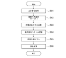
- FIG. 4 is a flowchart showing an operation process from the relative phase calculation to the positioning calculation by the CPU 101 which is a main part of the above-described radio wave receiver.
- step S ⁇ b> 31 the CPU 101 obtains a digital signal related to a reception signal having a plurality of frequencies after A / D conversion from the input interface 105. Thereby, A / D signal acquisition is performed.
- step S32 CPU 101, by the function of the relative phase synthesis unit 7, in step S32, a plurality of frequencies f 1 obtained, - calculates the relative phase from the respective digital signal f N. Thereby, the relative phase calculation (f 1 ,..., F N ) is performed.
- the CPU 101 performs an averaging operation on the relative phases calculated among a plurality of frequencies in step S33 by the function of the relative phase synthesis unit 7. Thereby, a relative phase averaging calculation is performed.
- step S34 the CPU 101 corrects the offset shift due to the averaging calculation and the phase shift between the reception channels by the shift process by the function of the relative phase shift unit 8. Thereby, a relative phase shift is performed.
- the CPU 101 uses the function of the positioning calculation unit 8 to perform positioning calculation by using the method described in Patent Document 1 using the relative phase after the shift processing in step S35.
- FIG. 5 is a diagram showing the experimental verification result of the positioning calculation by the displacement measuring apparatus 10 according to the first embodiment in relation to the displacement in the X-axis direction of the radio wave transmitter with respect to the number of samples.
- FIG. 6 is a diagram illustrating data of experimental specifications.
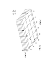
- FIG. 7 is a schematic diagram showing the positional relationship between the radio wave transmitter and the receiving antenna in the experiment in three-dimensional coordinates. However, in FIG. 7, the radio wave transmitter corresponds to Tx, and the plurality of receiving antennas correspond to Rx.
- the position of one radio wave transmitter Tx is measured by using six receiving antennas Rx, and the radio wave transmitter Tx is displaced by 10 mm in the X-axis direction at the intermediate point of measurement. I am letting. And the positioning result in each frequency single-piece
- the transmission frequencies are 922.5 MHz, 925.1 MHz, and 927.5 MHz.
- the number of positioning (number of samples) is 8 times.
- the radio wave transmitter Tx is displaced by 10 mm in the X-axis direction between the fourth sample and the fifth sample.
- the transmission power in the radio wave transmitter Tx is 20 mW and the transmission pulse length is 130 ms.
- the sampling frequency was 2 MHz.
- FIG. 5 shows in comparison the characteristics C1 ⁇ C4, and the theoretical characteristic C TV as follows.
- Characteristic C1 A characteristic related to the positioning result using the relative phase after the averaging calculation, and is indicated by a solid line.
- Characteristics C2 to C4 Characteristics related to the positioning result for each frequency alone, and are indicated by broken lines.
- Theoretical characteristic C TV A characteristic relating to the true value of the displacement, which is indicated by a dotted line.
- the characteristic C3 of 927.5 MHz is obtained by increasing the negative displacement value from the number of samples 1 to 4 in the displacement 0 mm in the X-axis direction, and then increasing the number of samples 5. If it exceeds, it shifts to a positive displacement value.
- the characteristic C4 of 922.5 MHz reaches a negative displacement value (not shown) along the X-axis direction when the number of samples is 1 to 2 when the displacement is 0 mm in the X-axis direction.
- the characteristic C2 of 925.1 MHz is a positive displacement value in the X-axis direction up to the number of samples 2, but reaches a positive displacement value in the X-axis direction not shown in the number of samples 3.
- the characteristics C2, C3, and C4 have large variations.
- the number of samples is 3, and in the characteristic C4, when the number of samples reaches 2, a cycle slip that erroneously estimates the integer value bias is generated.
- the positioning result is a true value as shown in the characteristic C1. It approaches the theoretical characteristic C of the TV , and the positioning accuracy improves. In order to improve the positioning accuracy, it is effective to average the relative phases at each of the plurality of frequencies when combining the relative phases for a plurality of frequencies. That is, according to the displacement measuring apparatus 10 according to the first embodiment, errors in measurement displacement can be reduced even in a multipath environment.
- FIG. 1 The displacement measuring apparatus according to the second embodiment is the same as the case of FIG. 1 in the basic configuration, but the detailed processing function is different.
- FIG. 8 is a block diagram showing a detailed configuration of the relative phase synthesizing unit 70 included in the radio wave receiver provided in the displacement measuring apparatus according to Embodiment 2 of the present invention.
- the relative phase synthesis unit 70 here includes a correlation matrix calculation unit 70a, a correlation matrix average unit 70b, and a maximum eigenvector calculation unit 70c.
- the correlation matrix calculation unit 70a calculates a correlation matrix for each of a plurality of frequencies from the reception signals for the reception antennas 2 (1) to 2 (M).
- the correlation matrix averaging unit 70b averages the correlation matrix among a plurality of frequencies.
- the maximum eigenvector computing unit 70c calculates and outputs a relative phase from the eigenvector corresponding to the maximum eigenvalue of the correlation matrix after being averaged by the correlation matrix averaging unit 70b.
- the positioning calculation is performed in the same manner as in the first embodiment, using the average value of the relative phase ⁇ after the averaging calculation.
- FIG. 9 is a flowchart showing an operation process from the correlation matrix calculation to the positioning calculation by the CPU 101 of the main part of the radio wave receiver according to the second embodiment.
- step S ⁇ b> 81 the CPU 101 acquires a digital signal related to a reception signal having a plurality of frequencies after A / D conversion from the input interface 105. Thereby, A / D signal acquisition is performed.
- the CPU 101 calculates a correlation matrix from each of the acquired digital signals of the plurality of frequencies f 1 ,..., F N in step S 82 by the function of the correlation matrix calculation unit 70 a of the relative phase synthesis unit 70. Thereby, the correlation matrix calculation (f 1 ,... F N ) is performed.
- the CPU 101 averages the correlation matrix calculated among the plurality of frequencies in step S83 by the function of the correlation matrix averaging unit 70b of the relative phase synthesis unit 70. Thereby, a correlation matrix averaging operation is performed.
- step S84 the CPU 101 calculates the eigenvector corresponding to the maximum eigenvalue of the correlation matrix after the averaging calculation by the function of the maximum eigenvector calculation unit 70c of the relative phase synthesis unit 70. Thereby, the maximum eigenvector calculation is performed.
- step S85 the CPU 101 corrects the offset shift due to the averaging calculation and the phase shift between the reception channels by the shift process by the function of the relative phase shift unit 8. Thereby, a relative phase shift is performed.
- the CPU 101 uses the function of the positioning calculation unit 8 to perform positioning calculation by using the method described in Patent Document 1 using the relative phase after the shift processing in step S86.
- the positioning error can also be reduced by the method of the second embodiment.
- the displacement measuring apparatus 10 since the relative phases are averaged, even if the signal-to-noise ratio is different at a plurality of frequencies, the information is not taken into consideration at the time of averaging.
- the averaging calculation is performed using the correlation matrix including the amplitude information of a plurality of frequencies, there is an effect that weighted averaging according to the amplitude for each frequency can be executed. It is done.
Landscapes
- Physics & Mathematics (AREA)
- Engineering & Computer Science (AREA)
- General Physics & Mathematics (AREA)
- Radar, Positioning & Navigation (AREA)
- Remote Sensing (AREA)
- Position Fixing By Use Of Radio Waves (AREA)
Abstract
変位計測装置は、計測点に設置されると共に、送信アンテナから複数周波数の電波を送信する電波発信機と、固定点に設置されると共に、送信アンテナからの複数周波数の電波を受信した結果に基づいて、送信アンテナの測位値を演算する電波受信機と、を備える。電波受信機は、複数周波数の電波を受信した結果を示す受信信号を出力する複数の受信アンテナと、複数の受信アンテナ間における相対位相を、複数周波数の分、合成する相対位相合成部と、相対位相合成部で合成された複数周波数の間の相対位相をシフトする相対位相シフト部と、相対位相シフト部によるシフトの後の相対位相に基づいて、送信アンテナの測位値を演算する測位演算部と、を備える。
Description
本発明は、斜面、構造物等の被測定対象への変位・振動等の計測に好適な変位計測装置に関する。
従来、電波を用いて被測定対象の震動による歪み、基準位置からの変位量を測定する技術として、例えば構造物の震動変位計測装置(例えば、特許文献1参照)が挙げられる。
この震動変位計測装置は、構造物の計測点毎に電波送信機を設置し、各電波送信機からの異なる送信タイミングの電波を、固定点に設置した複数の受信アンテナで受信する。そして、各受信アンテナに接続された電波受信機において、2つの受信アンテナ間の遅延時間差から構造物の各計測点の位置を同時に独立して推定する。但し、この震動変位計測装置では、電波発信機の送信アンテナと各受信アンテナとの周囲に、電波への反射源が無い理想的な使用環境が想定されている。
上述した特許文献1に係る技術では、電波への反射源が無い理想的な使用環境を想定している。このため、使用環境に反射源が存在する所謂マルチパス環境であれば、計測変位に誤差が生じてしまうという問題がある。その理由は、各受信アンテナに複数波が到来し、複数波の合成で位相が真値から回転するためである。この結果、計測変位に誤差が生じてしまう。因みに、反射源としては、例えば、草木等の植生、地面、建物、ポール等の構造物が挙げられる。
そこで、こうした場合の解決策として、植生であれば、除去を行うことが考えられる。しかしながら、年単位の長期的な変位計測を行う場合には、植生の除去費用が膨大になってしまう。その他の解決策として、電波発信機の送信アンテナ、及び各受信アンテナに指向性を持たせる手法が考えられる。ところが、複数の電波発信機を用いて、例えば、地滑りの危険性がある斜面を広範囲に計測する場合には、指向性の制御が困難になってしまうばかりでなく、装置規模が大きくなってしまう。このため、指向性を持たせる手法は、解決策としては好ましくない。
本発明は、このような問題点を解決すべくなされたもので、マルチパス環境でも計測変位の誤差を低減できる変位計測装置を提供することを目的とする。
上記目的を達成するために、本発明の変位計測装置は、計測点に設置される電波発信機と、固定点に設置される電波受信機と、を備えた構成であって、電波発信機は、送信アンテナを介して複数周波数の電波を送信し、電波受信機は、電波発信機の送信アンテナを介して、電波発信機から送信された複数周波数の電波の受信結果に基づいて、送信アンテナの測位値を演算し、電波受信機は、電波発信機から送信される複数周波数の電波の受信結果を示す受信信号を出力するM(但し、Mは2以上の正の整数とする)個の受信アンテナと、M個の受信アンテナ間における相対位相を、複数周波数の分、合成する相対位相合成部と、相対位相合成部で合成された相対位相を、M個の受信アンテナ間における観測位相差に基づいてシフトする相対位相シフト部と、相対位相シフト部によるシフト後の相対位相に基づいて、送信アンテナの測位値を演算する測位演算部と、を備える。
本発明によれば、上記構成により、マルチパス環境でも計測変位の誤差を低減できるようになる。
以下、本発明の変位計測装置に係る幾つかの実施の形態について、図面を参照して詳細に説明する。
実施の形態1.
図1は、本発明の実施の形態1に係る変位計測装置10の基本構成を示したブロック図である。
図1は、本発明の実施の形態1に係る変位計測装置10の基本構成を示したブロック図である。
図1を参照すれば、変位計測装置10は、計測点に設置される複数の電波発信機1(1)~1(L)と、固定点に設置される電波受信機と、を備える。但し、Lは、自然数とする。ここで、複数の電波発信機1(1)~1(L)のそれぞれは、送信アンテナから複数周波数の電波を送信する。一方、電波受信機は、それぞれの送信アンテナからの複数周波数の電波を受信した結果に基づいて、それぞれの送信アンテナの測位値を演算する。
電波受信機は、複数の受信アンテナ2(1)~2(M)、複数の伝送用ケーブル3(1)~3(M)、複数の低雑音増幅器(Low Noise Amplier:LNA)4(1)~4(M)、複数の周波数変換器(D/C)5(1)~5(M)、及び複数のA/D変換器6(1)~6(M)を備え、図1に示すように、M系統の受信回路が構成されている。但し、Mは、2以上の正の整数とする。また、電波受信機は、複数のA/D変換器6(1)~6(M)の後段に、相対位相合成部7、相対位相シフト部8、及び測位演算部9を備えて構成される。
受信アンテナ2(1)~2(M)は、複数の電波発信機1(1)~1(L)の送信アンテナからの複数周波数の電波を受信した結果を示す複数系統の受信信号を、それぞれ伝送用ケーブル3(1)~3(M)へ出力する。例えば、受信アンテナ(M)は、電波発信機1(1)~1(L)の送信アンテナからの複数周波数の電波を受信した結果を示す複数系統の受信信号を伝送用ケーブル3(M)へ出力する。
低雑音増幅器4(1)~4(M)は、伝送用ケーブル3(1)~3(M)に伝送された複数系統の受信信号を低雑音増幅して周波数変換器5(1)~5(M)へ引き渡す。例えば、低雑音増幅器4(M)は、伝送用ケーブル3(M)に伝送された複数系統の受信信号を低雑音増幅して周波数変換器5(M)へ引き渡す。
周波数変換器5(1)~5(M)では、それぞれ複数系統の低雑音増幅された受信信号を、周波数変換する。例えば周波数変換器5(M)では、低雑音増幅器4(M)によって、複数系統の低雑音増幅された受信信号を、周波数変換する。
A/D変換器6(1)~6(M)は、それぞれ複数系統の周波数変換された受信信号のアナログ信号を、デジタル信号に変換する。例えば、A/D変換器6(M)は、周波数変換器5(M)によって、複数系統の周波数変換された受信信号のアナログ信号を、デジタル信号に変換する。
また、相対位相合成部7は、入力されたそれぞれの複数系統のデジタル信号に対して、受信アンテナ2(1)~2(M)間における相対位相を、複数周波数分、合成する。相対位相シフト部8は、合成された複数周波数の間の相対位相をシフトする。測位演算部9は、シフト後の相対位相に基づいて、送信アンテナの測位値を演算する。
図2は、上述した変位計測装置10に備えられる電波受信機の要部におけるハードウェア構成を示すブロック図である。
図2を参照すれば、ここでの電波受信機は、A/D変換器6(1)~6(M)の後段に該当する相対位相合成部7、相対位相シフト部8、及び測位演算部9の機能構成を、ハードウェア上で示したものである。
具体的に云えば、電波受信機は、ハードウェア上において、CPU(Central Processing Unit)101、メモリ102、補助記憶装置103、表示装置104、及び入力インターフェース105が、データバスで接続されて構成される。入力インターフェース105は、A/D変換器6(1)~6(M)で得られるそれぞれの複数系統の周波数変換された受信信号のデジタル信号を入力する。上述した相対位相合成部7、相対位相シフト部8、及び測位演算部9の機能処理は、メモリ102に記憶されたプログラム及びデータに従って、CPU101の中央演算処理で実施される。CPU101の中央演算処理で得られる測位結果は、補助記憶装置103に記憶蓄積されると共に、表示装置104に表示される。
次に、図1に示す変位計測装置10の動作処理について説明する。計測点に設置された電波発信機1(1)~1(L)は、計測時に送信アンテナから同時か、或いは、時分割で、複数周波数の電波を送信する。ここで、電波発信機1(1)~2(L)は、計測点として、例えば地滑りの危険性がある斜面、構造物等の変位が予想される場所に設置される。
電波受信機では、それぞれの送信アンテナからの複数周波数の電波を複数固定点に設置した受信アンテナ2(1)~2(M)で、個別に受信する。受信アンテナ2(1)~2(M)は、受信結果の受信信号を、個別に伝送用ケーブル3(1)~3(M)へ出力する。
伝送用ケーブル3(1)~3(M)を通過した受信信号は、低雑音増幅器4(1)~4(M)で個別に増幅された後、周波数変換器5(1)~5(M)へ個別に出力される。因みに、伝送用ケーブル3(1)~3(M)での電力減衰が大きい場合には、受信アンテナ2(1)~2(M)に低雑音増幅器を追加しても良い。
周波数変換器5(1)~5(M)は、それぞれ増幅された受信信号を、それぞれ個別に所望の中間周波数に変換してから、A/D変換器(1)~6(M)へ個別に出力する。A/D変換器6(1)~6(M)では、それぞれの受信信号の中間周波数を、個別に受信アンテナ2(1)~2(M)の周波数毎のデジタル信号に変換する。
相対位相合成部7では、受信アンテナ2(1)~2(M)の周波数毎のデジタル信号に基づいて、受信アンテナ2(1)~2(M)間における相対位相を、複数周波数分、合成する。相対位相シフト部8では、相対位相合成部7で合成された相対位相に対して、位相のシフトを行う。測位演算部9では、相対位相シフト部8によるシフト後の相対位相を用いて、測位演算を行う。ここでの測位演算は、例えば、特許文献1等に記載された位相差測位手法を適用することができる。
実施の形態1に係る変位計測装置10は、測位演算部9から出力される測位結果を時系列で並べることによって、電波発信機1(1)~1(L)のそれぞれの変位を計測することができる。この結果、マルチパス環境でも計測変位の誤差を低減できるようになる。
図3は、図1に示す変位計測装置に備えられる電波受信機に含まれる相対位相合成部7の細部構成を示したブロック図である。
図3を参照すれば、相対位相合成部7は、複数周波数の毎に相対位相を演算する相対位相演算部7aと、複数周波数における相対位相を平均化演算する相対位相平均部7bと、を備えて構成される。
以下は、電波受信機の要部である相対位相合成部7、相対位相シフト部8、及び測位演算部9の処理動作について詳述する。nがサンプル数を表すものとして、周波数fk(k=1,2,・,K)における受信アンテナ素子数Mの要素を持つ受信信号ベクトルをxfk[n]とする。ベクトルの各要素は、A/D変換によって得られた受信アンテナ素子の受信信号であり、複素応答(即ち、伝播による位相回転と減衰)が乗算された送信信号に、受信機雑音が加算されたものである。
位相差測位演算では、電波発信機1(1)~1(L)から受信アンテナ2(1)~2(M)へ送信した信号の位相差(到達時間差)を用いて、電波発信機1(1)~1(L)のそれぞれの測位を行う。一般には、受信アンテナ2(1)~2(M)のうちの特定の受信アンテナを基準としたときの、各受信アンテナ2(1)~2(M)の受信位相差(相対位相)に基づいて測位が行われる。
相対位相合成部7では、受信アンテナ2(1)~2(M)の複数周波数毎のデジタル信号から受信アンテナ2(1)~2(M)間における相対位相を複数周波数分、合成する。相対位相は、例えば、受信信号の相関行列から得られる固有ベクトルを用いることで算出できる。周波数fkにおける受信信号の相関行列Rxx,fkは、下式(1)のように表わされる。

但し、上式(1)のE[]は、集合平均演算を表わし、xHは、ベクトルxのエルミート転置を表わす。厳密に云えば、相関行列Rxx,fkを正確に得ることは不可能である。このため、エルゴード性に基づくサンプル平均を用い、下式(2)のように表わされる相関行列推定を行う。

但し、上式(2)のNは、サンプル数を表わす。相関行列推定の最大固有値をγfk、最大固有値γfkに対応する固有ベクトルをqfkとしたとき、下式(3)の関係が成り立つ。

干渉波等が無い理想的な環境では、相関行列の固有値展開により得られた最大固有値に対応する固有ベクトルが、受信アンテナ2(1)~2(M)の複素応答からなる複素応答ベクトルに対応する。よって、複数周波数の相対位相ベクトルpfkは、下式(4)のように表わされる

但し、上式(4)の∠qを、ベクトルqの位相角演算とする。
マルチパスが存在する環境での位相差測位では、電波発信機1(1)~1(L)と、受信アンテナ2(1)~2(M)との間に複数の経路が存在することで、到来波が合成されてしまう。これにより、受信位相が、直接波のみからなる受信位相から回転してしまうため、測位結果に誤差が生じるリスクがある。加えて、到来波同士が打ち消しあい、信号対雑音比(SNR)が低下するリスクもある。そこで、本実施の形態1では、周波数毎に算出された相対位相を平均化演算することにより、それらのリスクの低減化を図る。平均化演算後の相対位相をφとすると、相対位相φは、下式(5)のように表わされる。

但し、上式(5)の記号〈〉における上付きK、及び下付きk=1は、k=1,2,・,Kについての平均化演算を表わす。
以下には、相対位相の複数周波数の平均化演算により、誤差が低減できる理由について説明する。独立で同一な分布をする確率変数U1,U2,・,UKの和をZとすると、中心極限定理より、下式(6)の関係が成り立つ。

但し、上式(6)のN(z|μ,σ2)は、和Zが平均μ分散σ2の正規分布をするときの確率密度分布を表わす。→の記号は、Kが大きくなるに従い、和Zの分布がN(z|Kμ,Kσ2)に漸近することを意味する。従って、相対位相が周波数間で独立かつ同一分布であるとみなせるとき、複数周波数の相対位相の和の標準偏差は、理想的には、1/K0.5で減少する。例えば、平均化演算する周波数の数をK=4としたとき、K=1のときと比べ、誤差のばらつきは、半分に減少する。
また、電波発信機1(1)~1(L)から送信する信号の周波数と、その最大周波数幅とに対して、電波発信機1(1)~1(L)の変位が十分小さいとき、観測した相対位相の変位は、複数周波数間でほぼ同一とみなせる。
例えば、電波発信機から922.5MHzと927.5MHzとの2周波数で信号を送信する場合を想定する。簡単のため、電波発信機1(1)~1(L)を挟むように2本の受信アンテナ2(1)、2(2)が設置され、電波発信機1(1)~1(L)と受信アンテナ2(1)~2(M)とが直線状に並ぶ状況を仮定する。電波発信機1(1)~1(L)が直線に沿って100mm変位したとき、複数周波数における位相差の変位前後の差を算出する。
具体的に云えば、変位前の差は、10・10-3・2・[922.5・106/299792458]に360を乗じた22.16[deg]となる。また、変位後の差は、10・10-3・2・[927.5・106/299792458]に360を乗じた22.28[deg]となる。これは、複数周波数間で0.12[deg]、約0.1mmのずれしか存在しないことを示す。このような場合では、周波数差による位相回転の差を特に考慮せずに平均化演算しても、周波数差に起因する誤差が無視できる程、小さい。
また、平均化演算の際に用いる複数周波数の相対位相は、時間軸に対して滑らかになるように、必要に応じてアンラップ処理を実施する。尚、上記した例では、受信信号の相関行列の固有ベクトルを用いて複数周波数の相対位相を算出する場合を説明した。これに代えて、或る基準とする受信アンテナの受信信号と受信アンテナ2(1)~2(M)の受信信号との複素共役を乗算することにより、相対位相を算出しても良い。周波数fkにおける受信信号ベクトルは、下式(7)のように表わされる。

但し、上式(7)の添え字Tは、行列の転置を表わす。また、基準となるアンテナmrefに対する受信アンテナm(m=1,2,・,M)の相対位相は、下式(8)のように表わされる。

上式(8)の*は複素共役を表わし、pfk=(pfk,1,pfk,2,・,pfk,M)Tである。相対位相合成部7で得られた相対位相には、平均化演算によるオフセットのずれが発生している。このオフセットのずれは、マルチパス・遮蔽等の周囲環境が変わらない理想状態において、時間変動せず、それぞれのチャネルで一定の値を持つという特徴がある。
加えて、受信アンテナ2(1)~2(M)から信号処理までの無線周波数回路における信号伝送時に、チャネル間で異なる位相遅延が発生する。精度の高い測位を行うためには、これらの位相オフセットを補正する必要がある。このため、相対位相シフト部8において、平均化演算及び無線周波数回路で発生するチャネル間の位相オフセットを、同時に補償する処理を行う。
例えば、電波発信機l(l=1,2,・,L)からの電波受信機mの観測位相は、下式(9)のように表わされる。

但し、上式(9)のslは、電波送信機lの初期位相、umは、電波受信機mの位相遅延量、amは、平均化演算による位相オフセット、Nl,mは、整数値バイアス、rl,mは、電波送受信機間の距離を表わす。また、電波送受信機間の距離rl,mは、電波送信機lの位置(xl,yl,zl)、既知の電波受信機mの位置(xm,ym,zm)を用いて、下式(10)のように表わされる。

上式(10)によれば、電波受信機mの位相遅延量umと平均化演算による位相オフセットamとについては、それぞれ電波受信機mにのみ依存する。このため、電波受信機mの位相遅延量umがまだ求まっていない場合、逐次推定を行う場合等は、電波受信機mの位相遅延量umと平均化演算による位相オフセットamとの和vmとして、一括で推定して良い。この場合、観測位相は、下式(11)のように書き換えられる。

また、電波送信機lの位置は、電波受信機mとして、2つの電波受信機m1、m2間における観測位相差を用い、下式(12)の連立方程式を解くことで求められる。

但し、上式(12)では、位相シフト量θm1,m2=2π(vm1-vm2)/λとしている。上式(12)のうち、整数値バイアスは、前回の測位値等の位置情報を用いて求めることができる。位相シフト量θm1,m2の算出には、トータルステーション等のレーザを用いた測位、或いは、GNSS(Global Navigation Satellite System)測位によって、その位置が既知である電波送信機lの座標を用いる。そして、電波送信機lと電波受信機m1、m2との観測位相の差分と、電波受信機m1、m2の配置より求めた位相差の差分とより求めることができる。位相シフト量θm1,m2θは、下式(13)のように表わされる。

但し、上式(13)のdec[ζ]は、ζに最も近い整数をζから減算する整数部除去演算を表わす。また、kを任意の電波受信機mの番号としたとき、電波送受信機間距離は、下式(14)で表わされる。

ところで、位置が既知の電波送信機lが複数ある場合には、電波送信機lについての平均化操作を行うことで、精度の向上が期待できる。平均化演算後の位相シフト量は、下式(15)で表わされる。

以上、電波受信機mの位相遅延量umと、平均化演算による位相オフセットamとの和vmを一括で推定した場合について述べた。しかし、電波受信機mの位相遅延量umが測位前のキャリブレーション等により既知である場合、或いは、無視できる場合には、位相オフセットamのみを推定し、シフトを行えば良い。
位相オフセットamは、基準周波数の相対位相の初期値と、平均化演算後の相対位相の初期値との差分で求めることができる。基準周波数をfrefとした際の基準周波数の相対位相の初期値をpfref,0、平均演算後の相対位相の初期値をφ0としたとき、シフト量のベクトル推定値は、下式(16)で表わされる。

但し、上式(16)の導出に関連するシフト量のベクトルaは、a=(a1,a2,・,aM)Tである。また、下式(17)のように、平均化演算すると、シフト量の精度を向上することができる。

但し、上式(17)のpfref,C、φDは、それぞれ、c(c=1,2,・,C)番目における基準周波数の相対位相、d(d=1,2,・,D)番目における平均後の相対位相を表わしている。
要するに、相対位相シフト部8は、相対位相平均部7で平均化演算した後の相対位相を、電波発信機1(1)~2(L)と受信アンテナ2(1)~2(M)との測位値より求めた相対位相の位置にシフトする機能を持つ。或いは、相対位相シフト部8は、相対位相平均部7で平均化演算した後の相対位相を、基準周波数frefの相対位相の初期値へシフトする機能を持つ。
図4は、上述した電波受信機の要部であるCPU101による相対位相演算から測位演算に至る動作処理を示したフローチャートである。
図4を参照すれば、CPU101は、まずステップS31において、入力インターフェース105からA/D変換後の、複数周波数の受信信号に係るデジタル信号を取得する。これにより、A/D信号取得が行われる。
次に、CPU101は、相対位相合成部7の機能により、ステップS32において、取得した複数周波数f1,・,fNのデジタル信号のそれぞれから相対位相を演算する。これにより、相対位相演算(f1,・,fN)が行われる。
更に、CPU101は、相対位相合成部7の機能により、ステップS33において、複数周波数間で算出された相対位相を平均化演算する。これにより、相対位相平均化演算が行われる。
引き続き、CPU101は、相対位相シフト部8の機能により、ステップS34において、平均化演算によるオフセットずれ及び受信チャネル間の位相ずれを、シフト処理によって補正する。これにより、相対位相シフトが行われる。
最後に、CPU101は、測位演算部8の機能により、ステップS35において、シフト処理後の相対位相を用いて、特許文献1記載の手法等により測位演算を行う。
図5は、実施の形態1に係る変位計測装置10による測位演算の実験検証結果を、サンプル数に対する電波発信機のX軸方向での変位の関係で示した図である。また、図6は、実験の諸元のデータを例示した図である。更に、図7は、実験における電波発信機と受信アンテナとの位置関係を3次元座標で示した模式図である。但し、図7中では、電波発信機がTxに対応し、複数の受信アンテナがRxに対応している。
この実験では、図7に示されるように、1台の電波発信機Txの位置を6本の受信アンテナRxを用いて測位し、計測の中間時点で電波発信機TxをX軸方向に10mm変位させている。そして、各周波数単体での測位結果と、相対位相の平均化演算後の測位結果と、を比較した。
具体的に云えば、図6中に示されるように、送信周波数は、922.5MHz、925.1MHz、927.5MHzである。測位回数(サンプル数)は、8回である。また、電波発信機Txを4サンプル目と5サンプル目との間でX軸方向に10mm変位させている。更に、電波発信機Txにおける送信電力を20mW、送信パルス長を130msとしている。その他、サンプリング周波数を2MHzとした。
図5では、以下のような特性C1~C4、および理論特性CTVを対比して示している。特性C1:平均化演算後の相対位相を用いた測位結果に係る特性であり、実線で示されている。特性C2~C4:各周波数単体での測位結果に係る特性であり、破線で示されている。理論特性CTV:変位の真値に係る特性であり、点線で示されている。
図5を参照すれば、927.5MHzの特性C3は、X軸方向での変位0mmにあるサンプル数1からサンプル数4に至るまでの間、負の変位値を増大させた後、サンプル数5を超えると、正の変位値に移行している。また、922.5MHzの特性C4は、X軸方向での変位0mmのサンプル数1からサンプル数2に至った時点で、X軸方向に沿った図示されない負の変位値に到達している。更に、925.1MHzの特性C2は、サンプル数2までは、X軸方向の正の変位値にあるが、サンプル数3で図示されないX軸方向の正の変位値に到達している。
何れにしても、各周波数単体での測位結果によれば、特性C2、C3、C4では、ばらつきが大きくなっている。殊に、特性C2では、サンプル数3、特性C4では、サンプル数2に至った時点で、整数値バイアスを誤推定するサイクルスリップが発生している様子が判る。しかしながら、本実施の形態1のように、相対位相を複数周波数分、合成した後に観測位相差に基づいてシフトしてから測位演算を行うと、特性C1に示されるように、測位結果が真値の理論特性CTVに近付き、測位精度が改善する。測位精度の改善には、相対位相を複数周波数分、合成する際、複数周波数のそれぞれにおける相対位相を平均化演算することが効果的である。即ち、実施の形態1に係る変位計測装置10によれば、マルチパス環境でも計測変位の誤差を低減することができる。
実施の形態2.
実施の形態2に係る変位計測装置は、基本構成上、図1の場合と同様であるが、細部の処理機能が相違する。
実施の形態2に係る変位計測装置は、基本構成上、図1の場合と同様であるが、細部の処理機能が相違する。
図8は、本発明の実施の形態2に係る変位計測装置に備えられる電波受信機に含まれる相対位相合成部70の細部構成を示したブロック図である。
図8を参照すれば、ここでの相対位相合成部70は、相関行列演算部70a、相関行列平均部70b、最大固有ベクトル演算部70cを備えて構成される。相関行列演算部70aは、受信アンテナ2(1)~2(M)毎の受信信号から複数周波数毎に相関行列を演算する。相関行列平均部70bは、相関行列を複数周波数の間で平均化演算する。最大固有ベクトル演算部70cは、相関行列平均部70bで平均化した後の相関行列の最大固有値に対応する固有ベクトルから相対位相を算出して出力する。
平均化演算後の相関行列は、下式(18)のように表わされる。

また、平均化演算後の相関行列の最大固有値γの平均値、対応する固有ベクトルqの平均値を用いると、平均化演算後の相関行列との関係は、下式(19)のように表わされる。

これにより、実施の形態2に係る平均化演算後の相対位相φの平均値は、下式(20)のように表わされる。

以降、平均化演算後の相対位相φの平均値を用いて、実施の形態1の場合と同様に測位演算を行う。
図9は、実施の形態2に係る電波受信機の要部のCPU101による相関行列演算から測位演算に至る動作処理を示したフローチャートである。
図9を参照すれば、CPU101は、まずステップS81において、入力インターフェース105からA/D変換後の複数周波数の受信信号に係るデジタル信号を取得する。これにより、A/D信号取得が行われる。
次に、CPU101は、相対位相合成部70の相関行列演算部70aの機能により、ステップS82において、取得した複数周波数f1,・,fNのデジタル信号のそれぞれから相関行列を演算する。これにより、相関行列演算(f1,・,fN)が行われる。
更に、CPU101は、相対位相合成部70の相関行列平均部70bの機能により、ステップS83において、複数周波数間で算出された相関行列を平均化演算する。これにより、相関行列平均化演算が行われる。
引き続き、CPU101は、相対位相合成部70の最大固有ベクトル演算部70cの機能により、ステップS84において、平均化演算後の相関行列の最大固有値に対応する固有ベクトルを算出する。これにより、最大固有ベクトル演算が行われる。
この後は、CPU101は、相対位相シフト部8の機能により、ステップS85において、平均化演算によるオフセットずれ及び受信チャネル間の位相ずれをシフト処理によって補正する。これにより、相対位相シフトが行われる。
最後に、CPU101は、測位演算部8の機能により、ステップS86において、シフト処理後の相対位相を用いて、特許文献1記載の手法等により測位演算を行う。
以上に説明したように、本実施の形態2の手法によっても、測位誤差を低減することができる。因みに、先の実施の形態1に係る変位計測装置10では、相対位相を平均するため、複数周波数で信号対雑音比が異なっていても、平均化時にその情報は考慮されない。これに対し、本実施の形態2では、複数周波数の振幅情報が含まれている相関行列を用いた平均化演算行うため、周波数毎の振幅に合わせた重み付き平均化を実行できるという効果が得られる。
1(1)~1(L) 電波発信機、2(1)~2(M) 受信アンテナ、3(1)~3(M) 伝送用ケーブル、4(1)~4(M) 低雑音増幅器(LNA)、5(1)~5(M) 周波数変換器(D/C)、6(1)~6(M) A/D変換器、7、70 相対位相合成部、7a 相対位相演算部、7b 相対位相平均部、8 相対位相シフト部、9 測位演算部、10 変位計測装置、70a 相関行列演算部、70b 相関行列平均部、70c 最大固有ベクトル演算部、101 CPU、102 メモリ、103 補助記憶装置、104 表示装置、105 入力インターフェース。
Claims (5)
- 計測点に設置される電波発信機と、固定点に設置される電波受信機と、を備えた変位計測装置であって、
前記電波発信機は、送信アンテナを介して複数周波数の電波を送信し、
前記電波受信機は、前記電波発信機の送信アンテナを介して、当該電波発信機から送信された前記複数周波数の電波の受信結果に基づいて、当該送信アンテナの測位値を演算し、
前記電波受信機は、
前記電波発信機から送信される前記複数周波数の電波の受信結果を示す受信信号を出力するM(但し、Mは2以上の正の整数とする)個の受信アンテナと、
前記M個の受信アンテナ間における相対位相を、前記複数周波数の分、合成する相対位相合成部と、
前記相対位相合成部で合成された相対位相を、前記M個の受信アンテナ間における観測位相差に基づいてシフトする相対位相シフト部と、
前記相対位相シフト部によるシフト後の相対位相に基づいて、前記送信アンテナの測位値を演算する測位演算部と、
を備える変位計測装置。 - 前記相対位相合成部は、
前記相対位相を前記複数周波数のそれぞれについて演算する相対位相演算部と、
前記複数周波数のそれぞれにおける相対位相を平均化演算する相対位相平均部と、
を含む請求項1に記載の変位計測装置。 - 前記相対位相合成部は、
前記M個の受信アンテナ毎の受信信号から相関行列を演算する相関行列演算部と、
前記相関行列を前記複数周波数の間で平均化演算する相関行列平均部と、
前記相関行列平均部で平均化された後の相関行列の最大固有値に対応する固有ベクトルから、相対位相を算出する最大固有ベクトル演算部と、
を含む請求項1に記載の変位計測装置。 - 前記相対位相シフト部は、前記相対位相平均部で平均化演算された後の相対位相を、前記電波発信機と前記M個の受信アンテナとの測位値より求めた相対位相の位置にシフトする
請求項2に記載の変位計測装置。 - 前記相対位相シフト部は、前記相対位相平均部で平均化演算された後の相対位相を、基準周波数の相対位相の初期値へシフトする
請求項2に記載の変位計測装置。
Priority Applications (4)
| Application Number | Priority Date | Filing Date | Title |
|---|---|---|---|
| JP2020515328A JP6781505B2 (ja) | 2018-04-23 | 2018-04-23 | 変位計測装置 |
| EP18916112.8A EP3767321A4 (en) | 2018-04-23 | 2018-04-23 | DISPLACEMENT MEASUREMENT DEVICE |
| PCT/JP2018/016485 WO2019207628A1 (ja) | 2018-04-23 | 2018-04-23 | 変位計測装置 |
| US17/072,153 US20210033695A1 (en) | 2018-04-23 | 2020-10-16 | Displacement measurement device |
Applications Claiming Priority (1)
| Application Number | Priority Date | Filing Date | Title |
|---|---|---|---|
| PCT/JP2018/016485 WO2019207628A1 (ja) | 2018-04-23 | 2018-04-23 | 変位計測装置 |
Related Child Applications (1)
| Application Number | Title | Priority Date | Filing Date |
|---|---|---|---|
| US17/072,153 Continuation US20210033695A1 (en) | 2018-04-23 | 2020-10-16 | Displacement measurement device |
Publications (1)
| Publication Number | Publication Date |
|---|---|
| WO2019207628A1 true WO2019207628A1 (ja) | 2019-10-31 |
Family
ID=68293622
Family Applications (1)
| Application Number | Title | Priority Date | Filing Date |
|---|---|---|---|
| PCT/JP2018/016485 Ceased WO2019207628A1 (ja) | 2018-04-23 | 2018-04-23 | 変位計測装置 |
Country Status (4)
| Country | Link |
|---|---|
| US (1) | US20210033695A1 (ja) |
| EP (1) | EP3767321A4 (ja) |
| JP (1) | JP6781505B2 (ja) |
| WO (1) | WO2019207628A1 (ja) |
Families Citing this family (1)
| Publication number | Priority date | Publication date | Assignee | Title |
|---|---|---|---|---|
| CN113362569B (zh) * | 2021-05-24 | 2022-12-06 | 机械工业第九设计研究院股份有限公司 | 一种土木工程用护坡滑坡监测方法及检测系统及方法 |
Citations (5)
| Publication number | Priority date | Publication date | Assignee | Title |
|---|---|---|---|---|
| JPS602403B2 (ja) | 1976-05-12 | 1985-01-21 | 旭化成株式会社 | ビスコ−スレ−ヨンの製造法 |
| JP3602403B2 (ja) * | 2000-03-24 | 2004-12-15 | 三菱電機株式会社 | 構造物の震動変位計測装置 |
| JP2007024642A (ja) * | 2005-07-14 | 2007-02-01 | Ntt Docomo Inc | 到来波方向推定装置、到来波方向推定方法および位置推定システム |
| JP2009053023A (ja) * | 2007-08-27 | 2009-03-12 | Mitsubishi Electric Corp | 変位計測装置 |
| JP2015201783A (ja) * | 2014-04-09 | 2015-11-12 | 住友電気工業株式会社 | 監視装置 |
Family Cites Families (4)
| Publication number | Priority date | Publication date | Assignee | Title |
|---|---|---|---|---|
| JP4980094B2 (ja) * | 2007-02-16 | 2012-07-18 | 三菱電機株式会社 | 変位計測装置 |
| JP4591565B2 (ja) * | 2008-07-14 | 2010-12-01 | ソニー株式会社 | 受信装置、無線通信システム、位置推定方法、及びプログラム |
| JP5620232B2 (ja) * | 2010-11-11 | 2014-11-05 | アルプス電気株式会社 | 距離測定装置 |
| CN109143197B (zh) * | 2018-09-27 | 2023-04-07 | 中国人民解放军空军工程大学 | 一种基于辅助阵元的极化mimo雷达的2d-doa和极化参数估计方法 |
-
2018
- 2018-04-23 JP JP2020515328A patent/JP6781505B2/ja active Active
- 2018-04-23 EP EP18916112.8A patent/EP3767321A4/en not_active Withdrawn
- 2018-04-23 WO PCT/JP2018/016485 patent/WO2019207628A1/ja not_active Ceased
-
2020
- 2020-10-16 US US17/072,153 patent/US20210033695A1/en not_active Abandoned
Patent Citations (5)
| Publication number | Priority date | Publication date | Assignee | Title |
|---|---|---|---|---|
| JPS602403B2 (ja) | 1976-05-12 | 1985-01-21 | 旭化成株式会社 | ビスコ−スレ−ヨンの製造法 |
| JP3602403B2 (ja) * | 2000-03-24 | 2004-12-15 | 三菱電機株式会社 | 構造物の震動変位計測装置 |
| JP2007024642A (ja) * | 2005-07-14 | 2007-02-01 | Ntt Docomo Inc | 到来波方向推定装置、到来波方向推定方法および位置推定システム |
| JP2009053023A (ja) * | 2007-08-27 | 2009-03-12 | Mitsubishi Electric Corp | 変位計測装置 |
| JP2015201783A (ja) * | 2014-04-09 | 2015-11-12 | 住友電気工業株式会社 | 監視装置 |
Non-Patent Citations (1)
| Title |
|---|
| See also references of EP3767321A4 * |
Also Published As
| Publication number | Publication date |
|---|---|
| US20210033695A1 (en) | 2021-02-04 |
| EP3767321A1 (en) | 2021-01-20 |
| EP3767321A4 (en) | 2021-03-17 |
| JP6781505B2 (ja) | 2020-11-04 |
| JPWO2019207628A1 (ja) | 2020-07-30 |
Similar Documents
| Publication | Publication Date | Title |
|---|---|---|
| US6366240B1 (en) | Location of aircraft with time difference of arrival | |
| CN107315183B (zh) | 导航卫星阵列天线接收系统的校准方法 | |
| EP2293103B1 (en) | System and method for correcting global navigation satellite system pseudorange measurements in receivers having controlled reception pattern antennas | |
| US8154445B2 (en) | System and method for frequency domain correction of global navigation satellite system pseudorance measurements in receivers having controlled reception pattern antennas | |
| US7570211B1 (en) | Digital beamforming method and apparatus for pointing and null steering without calibration or calculation of covariance matrix | |
| US11277200B2 (en) | System and method for estimating a pointing error of a satellite antenna | |
| US10578744B2 (en) | Method for calibrating a satellite radio navigation receiver | |
| CN109633578B (zh) | 一种双通道高精度相位标校系统及方法 | |
| WO2012164898A1 (ja) | レーダ装置 | |
| EP2366207A2 (en) | Compensation of beamforming errors in a communications system having widely spaced antenna elements | |
| US12542584B2 (en) | Systems, methods, and media for estimating an auto-correlation matrix for a transceiver | |
| CN114994678B (zh) | 多通道双基sar无线相位预失真方法、装置及电子设备 | |
| KR102479978B1 (ko) | 배열안테나를 이용한 글로벌 위성항법 시스템에 대한 기만신호 탐지 제거 장치 및 방법 | |
| JP2006349515A (ja) | 変位計測システム及び変位計測方法 | |
| KR101971685B1 (ko) | 빔포밍 gps 항재밍 시스템의 자체 교정 장치 및 방법 | |
| WO2023210451A1 (ja) | 測位システムおよびそれを備える車両、並びに測位方法 | |
| JP6781505B2 (ja) | 変位計測装置 | |
| US20260086192A1 (en) | Radar device with self-interference based compensation | |
| CN120602010A (zh) | 一种标定天线之间上行通道、下行通道相对时延的方法 | |
| JP2006304205A (ja) | アンテナ位相較正装置及びそれを用いた追尾アンテナ装置 | |
| JP2010071653A (ja) | 距離測定装置 | |
| JP2005195347A (ja) | 方探センサ及び電波発射源位置推定システム | |
| JP4215264B2 (ja) | 位置及び姿勢推定装置 | |
| JP4193939B2 (ja) | アレーアンテナ、到来波推定装置、及び平面アレーの合成方法 | |
| JP7482804B2 (ja) | アンテナ校正システム |
Legal Events
| Date | Code | Title | Description |
|---|---|---|---|
| 121 | Ep: the epo has been informed by wipo that ep was designated in this application |
Ref document number: 18916112 Country of ref document: EP Kind code of ref document: A1 |
|
| ENP | Entry into the national phase |
Ref document number: 2020515328 Country of ref document: JP Kind code of ref document: A |
|
| ENP | Entry into the national phase |
Ref document number: 2018916112 Country of ref document: EP Effective date: 20201012 |
|
| NENP | Non-entry into the national phase |
Ref country code: DE |