WO2019207814A1 - シートロック装置 - Google Patents
シートロック装置 Download PDFInfo
- Publication number
- WO2019207814A1 WO2019207814A1 PCT/JP2018/032777 JP2018032777W WO2019207814A1 WO 2019207814 A1 WO2019207814 A1 WO 2019207814A1 JP 2018032777 W JP2018032777 W JP 2018032777W WO 2019207814 A1 WO2019207814 A1 WO 2019207814A1
- Authority
- WO
- WIPO (PCT)
- Prior art keywords
- striker
- lock device
- seat lock
- cover
- seat
- Prior art date
- Legal status (The legal status is an assumption and is not a legal conclusion. Google has not performed a legal analysis and makes no representation as to the accuracy of the status listed.)
- Ceased
Links
Images

Classifications
-
- B—PERFORMING OPERATIONS; TRANSPORTING
- B60—VEHICLES IN GENERAL
- B60N—SEATS SPECIALLY ADAPTED FOR VEHICLES; VEHICLE PASSENGER ACCOMMODATION NOT OTHERWISE PROVIDED FOR
- B60N2/00—Seats specially adapted for vehicles; Arrangement or mounting of seats in vehicles
- B60N2/02—Seats specially adapted for vehicles; Arrangement or mounting of seats in vehicles the seat or part thereof being movable, e.g. adjustable
- B60N2/20—Seats specially adapted for vehicles; Arrangement or mounting of seats in vehicles the seat or part thereof being movable, e.g. adjustable the back-rest being tiltable, e.g. to permit easy access
-
- B—PERFORMING OPERATIONS; TRANSPORTING
- B60—VEHICLES IN GENERAL
- B60N—SEATS SPECIALLY ADAPTED FOR VEHICLES; VEHICLE PASSENGER ACCOMMODATION NOT OTHERWISE PROVIDED FOR
- B60N2/00—Seats specially adapted for vehicles; Arrangement or mounting of seats in vehicles
- B60N2/02—Seats specially adapted for vehicles; Arrangement or mounting of seats in vehicles the seat or part thereof being movable, e.g. adjustable
- B60N2/22—Seats specially adapted for vehicles; Arrangement or mounting of seats in vehicles the seat or part thereof being movable, e.g. adjustable the back-rest being adjustable
-
- B—PERFORMING OPERATIONS; TRANSPORTING
- B60—VEHICLES IN GENERAL
- B60N—SEATS SPECIALLY ADAPTED FOR VEHICLES; VEHICLE PASSENGER ACCOMMODATION NOT OTHERWISE PROVIDED FOR
- B60N2/00—Seats specially adapted for vehicles; Arrangement or mounting of seats in vehicles
- B60N2/90—Details or parts not otherwise provided for
-
- E—FIXED CONSTRUCTIONS
- E05—LOCKS; KEYS; WINDOW OR DOOR FITTINGS; SAFES
- E05B—LOCKS; ACCESSORIES THEREFOR; HANDCUFFS
- E05B65/00—Locks or fastenings for special use
Definitions
- the present invention relates to a seat lock device that holds a seat back configured to be able to be lifted in a locked state, and more particularly to a seat lock device that is at least partially covered with a cover.
- a vehicle seat has a seat cushion as a seating surface and a seat back as a backrest.
- the seat back is a standing posture for normal seating, and it is pushed forward for the convenience of loading. It is possible to switch between posture and posture.
- the seat lock device provided in the seat back In the standing posture for sitting, the seat lock device provided in the seat back is held in a locked state by being engaged with a striker fixed to the vehicle body, and is stabilized. Some of the standing postures can be switched in two steps by the internal mechanism of the seat lock device.
- the seat lock device is often covered with a cover mainly from the viewpoint of appearance design.
- the seat lock device basically includes a striker that enters from behind, a hook member that includes an engagement groove that engages with the striker, a shaft member that rotatably supports the hook member in the vicinity of the front end, and the shaft member is fixed.
- the case member is provided with a striker entry groove into which the striker enters (see, for example, Patent Document 1).
- the cover often covers the two-way surfaces of the outer surface and the rear surface of the seat lock device, and the assembly part is also provided in these two directions. And the assembly
- the seat lock device that can switch the seat back in two stages is increased in size and a cover that is larger in size is used, there is a high demand for simplifying the assembly work.
- the present invention has been made in view of the above-described problems, and an object of the present invention is to provide a seat lock device that can be easily assembled.
- a seat lock device is a seat lock device that holds a seat back in a vehicle in a locked state and is at least partially covered with a cover, A hook member having an engaging groove that engages with a striker entering from behind, a shaft member that rotatably supports the hook member in the vicinity of a front end thereof, a case member to which the shaft member is fixed, and the case A striker entry groove that is formed in the member and into which the striker enters, and a pair of holding projections that are provided on both sides of the striker entry groove and project toward the rear. It is characterized by being held by inserting a pair of the holding projections into a held hole provided.
- the case member has a case side surface portion in which the striker entry groove is formed, the pair of holding protrusions protrude from a side surface contact plate that contacts the case side surface portion, and the side surface contact plate has an opening hole. You may have.
- the front abutting plate fixed to the front surface portion of the case member may be provided, and the holding projection may be connected via a bent portion that bends backward from the front abutting plate.
- the striker is a first striker, and the first striker is integrally interlocked with a second striker at a constant distance, and the engagement groove is engaged with the first striker or the second striker.
- the seat back may be locked at two tilt angles.
- the pair of holding projections protruding rearward are provided above and below the striker entry groove, and the pair of holding projections are inserted into the held holes of the cover. Therefore, the assembling work is simple.
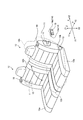
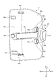
- FIG. 1 is a schematic perspective view showing a seat to which a seat lock device is applied.
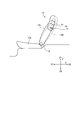
- FIG. 2 is a schematic side view showing a seat to which the seat lock device is applied.
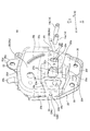
- FIG. 3 is a perspective view of the seat lock device.
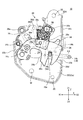
- FIG. 4 is a partially omitted side view of the seat lock device.
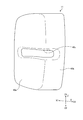
- FIG. 5 is a perspective view of the seat lock device with a cover attached.
- FIG. 6 is a perspective view of the cover.
- FIG. 7 is a perspective view of the cover engaged with the cover holding member as viewed from the inside.
- the seat lock device 10 As shown in FIGS. 1 and 2, the seat lock device 10 according to the present embodiment is applied to the left and right seats 12 of the vehicle, respectively. Part of the seat lock device 10 is covered with a cover 11.
- the seat 12 includes a seat cushion 12a as a seat surface and a seat back 12b as a backrest.
- the seat back 12b rotates about the seat back rotating shaft 13, and can be switched between a standing posture for normal seating and a forward-facing posture that leans forward for convenience of loading. .
- the standing posture can be switched between two stages of a standard first standing posture and a second standing posture having a deeper inclination by the mechanism of the seat lock device 10.
- the first standing posture of the seat back 12 b is indicated by a solid line
- the forward-falling posture and the second standing posture are indicated by a virtual line.
- the seat lock device 10 is provided slightly below the shoulder of the seat back 12b, and engages with the first striker 14a or the second striker 14b made of metal that is fixed to the vehicle body panel side. 12b can be locked in two standing postures. Further, by releasing the engagement between the seat lock device 10 and the first striker 14a and the second striker 14b, the seat back 12b can be brought down to the forward position.
- the first striker 14a and the second striker 14b are arranged in parallel at a fixed distance, the tips are connected to each other, one of them forms a rectangular shape, and the opening side is fixed to the striker base 15.
- Either the first striker 14a or the second striker 14b is also referred to as a striker 14 as a representative.
- the portions that are not covered by the cover 11 with the seat lock device 10 are covered with the seat back 12b, and the seat lock device 10 is almost completely invisible except for a very small portion where the striker 14 enters. Since the cover 11 is a visually recognized part, it has a slightly rounded overall design.
- the first striker 14a is first engaged with the seat lock device 10 to be in the first standing posture.
- the operating portion 16 provided on the shoulder portion of the seat back 12b
- the engagement between the seat lock device 10 and the first striker 14a is released, and the second striker 14b is engaged by tilting deeper. Then, it is locked in the second standing posture or returned to the forward posture by moving forward again.
- the engagement in the second standing posture is also released by operating the operation unit 16.
- the seat lock device 10 is applied to the left and right seats 12 of the vehicle, respectively.
- the left seat 12 front side in FIG. 1 of the vehicle and the seat lock device 10 inside the vehicle will be described as an example. .
- the front and rear, inside / outside, and top / bottom of the vehicle are used as directions, and the seat back 12b is basically in the first standing posture.
- the front-rear direction is X
- the front is X1
- the rear is X2
- the vehicle width direction is Y
- the inner direction is Y1
- the outer direction Y2
- the vertical direction is Z
- the upper direction is Z1
- the lower direction is Z2
- the relative operation of the seat lock device 10 and the striker 14 will be described assuming that the striker 14 is displaced with respect to the seat lock device 10.
- the seat lock device 10 includes an outer case (case member) 20, an inner case 22, a cover holding member 24, and a hook member 26 that is engaged with the striker 14.
- the hook member 26 is a part of the internal mechanism 28.
- the outer case 20, the inner case 22, and the cover holding member 24 are, for example, metal press-formed products.
- the hook member 26 has an engaging groove 26a with which the striker 14 is engaged, a loose fitting groove 26b, and a rotating shaft (shaft member) 26c.
- the engaging groove 26a is provided in the vicinity of the rear end, the loose fitting groove 26b is provided in the center, and the rotating shaft 26c is provided in the vicinity of the front end.
- the engaging groove 26a is a portion sandwiched between the corner portion 26d and the sub-corner portion 26e at the front and rear.
- the outer case 20 has an outer surface 20a covering the internal mechanism 28, a front surface 20b, a rear surface 20c, an upper surface 20d, and a lower surface 20e.
- the outer case 20 further includes two attachment pieces 20f that are folded back from the lower surface 20e and protrude downward, a mounting piece 20g that is folded back from the upper surface 20d and protrudes upward, and a holding protrusion that is folded back from the upper surface and protrudes upward. 20h.
- the holding projecting piece 20h is for fitting with the fitting portion of the operation portion 16 and temporarily holding it.
- the gap in the vehicle width direction between the outer side surface (case side surface) 20a and the hook member 26 is narrow.
- the outer side surface 20a and the rear surface 20c are provided with striker entry grooves 20i into which the striker 14 enters. Since the seat lock device 10 is a two-stage lock type, the first striker 14a enters the loose fitting groove 26b as will be described later, so that the striker entry groove 20i is formed longer in the vehicle length direction. Since the striker entry groove 20i is long, the seat lock device 10 is large accordingly, and the cover 11 covering it is also large.
- the striker entry groove 20i extends from the rear end of the outer case 20 to the vicinity of the rotating shaft 26c and crosses the rear surface 20c.
- the outer surface 20a supports the outer end of the rotating shaft 26c, and the rotating shaft 26c slightly protrudes from the outer surface 20a.
- the outer side surface 20a is provided with an arcuate bulging portion 20j that protrudes inward.
- the arcuate bulged portion 20j is provided in accordance with the rotation range of the hook member 26 with the rotation shaft 26c as the center, and has an effect of suppressing the hook member 26 from being displaced outward by an external force.
- the inner case 22 has an inner surface 22a (see FIG. 4) that covers the internal mechanism 28, a front surface 22b, and a rear surface 22c (see FIG. 4).
- the inner case 22 is combined with the outer case 20 to cover the internal mechanism 28.
- the internal mechanism 28 has a front surface covered with a front surface 20b and a front surface 22b, and a rear surface covered with a rear surface 20c and a rear surface 22c.
- the lower part of the inner case 22 extends downward to substantially the same position as the lower sides of the two attachment pieces 20 f of the outer case 20.
- a coaxial bolt hole 30 is provided in the lower part of the inner case 22 and the two attachment pieces 20f.
- the inner case 22 has a mounting piece 22d that protrudes upward.
- the mounting piece 22d and the mounting piece 20g have the same overlapping shape, and a coaxial bolt hole 32 is provided.
- the seat lock device 10 is fixed by inserting bolts into the bolt holes 30 and 32 and screwing them into the frame of the seat back 12b.
- the inner case 22 is provided with a striker entry groove 22e through which the striker 14 enters.
- the striker entry groove 22e of the inner case 22 and the striker entry groove 20i of the outer case 20 substantially overlap in a side view.
- the inner case 22 supports the inner end of the rotation shaft 26c.
- the cover holding member 24 includes a pair of holding protrusions 24a, a side contact plate 24b that is in contact with the outer surface 20a, and a front contact plate 24c that is fixed to the front surface 20b.
- the front contact plate 24c has a substantially triangular shape protruding inward, and is fixed to the front surface 20b by a central emboss 24d.
- the lower side of the front contact plate 24c substantially coincides with the lower side of the front surface 20b.
- the side contact plate 24b is connected via a bent portion that is bent 90 degrees rearward from the front contact plate 24c, and has a substantially trapezoidal shape that extends rearward.
- the lower side of the side contact plate 24b substantially coincides with the front portion of the lower surface 20e.
- the side contact plate 24b is provided with a substantially trapezoidal opening hole 24e that is slightly smaller than the outline, and does not interfere with the rotating shaft 26c.
- the plate thickness of the side contact plate 24b is formed slightly thicker than the protruding amount of the rotating shaft 26c.
- the opening hole 24e can reduce the weight.
- a curved portion 24f centering on the rotation shaft 26c is formed at the center of the vertically extending beam that forms the rear portion of the side contact plate 24b.
- a jig for assembly can be arranged around the rotating shaft 26c.
- the rear end of the curved portion 24f is substantially in contact with the front end of the striker entry groove 20i.
- Fixing means corresponding to the embossing 24d may be provided on the side contact plate 24b.
- the pair of holding protrusions 24a have a slightly long plate shape, and are bent slightly outward from the upper and lower ends of the side contact plate 24b, further bent backward, and directed rearward on both upper and lower sides of the striker entry groove 20i. Projecting in parallel.
- the extending direction of the holding projection 24a is substantially parallel to the striker entry groove 20i and the line L1 of the strike path of the striker 14.
- An appropriate gap is provided between the holding projection 24a and the outer surface 20a.
- the length of the holding protrusion 24a is substantially half of the length in the front-rear direction of the striker entry groove 20i. As will be described later, the holding protrusion 24 a holds the cover 11.
- the internal mechanism 28 includes a sensing lever 34, a cam plate 36, and an open lever 38 in addition to the hook member 26 described above.
- the hook member 26, the sensing lever 34, and the cam plate 36 are elastically urged clockwise in FIG. 4, and the open lever 38 is elastically urged counterclockwise.
- the hook member 26 is disposed on the near side in FIG. 4, the cam plate 36 is disposed in the back thereof, and the sensing lever 34 and the open lever 38 are disposed substantially vertically in the back.
- the sensing lever 34 is pivotally supported by a central rotating shaft 34a.
- the sensing lever 34 is a member whose angle changes when the rear end detection portion 34b abuts against or does not abut against the striker 14, and the front end pin 34c is a cam.
- the plate 36 is displaced.
- the cam plate 36 is supported by a rotating shaft 36a at the upper front end, and when the striker 14 is engaged with the engaging groove 26a, the lower cam surface 36b presses the restraining pin 26g of the hook member 26. Thus, the hook member 26 is stabilized.
- the cam pin 36 receives a large external force and the restraining pin 26g pushes up the cam surface 36b, the rear interlock surface 36c receives the interlock pin 26f of the hook member 26, so that the hook member 26 rotates excessively.
- the cam plate 36 is slightly rotated by operating the pin 36d by the open lever 38 when releasing the engagement between the striker 14 and the engagement groove 26a. Accordingly, the interlock pin 26f can enter the escape portion 36e, the hook member 26 can be rotated counterclockwise, and the engagement between the striker 14 and the engagement groove 26a is released.
- the open lever 38 is pivotally supported by an upper rotating shaft 38a and is rotated by a rod connected to the rod hole 38b.
- the cam release lever surface 38c slightly pushes up the pin 36d, and the fan-shaped cam holding curved surface 38d slides on the pin 36d to hold its position.
- the cam plate 36 is held at an appropriate release position.
- the hook release protrusion 38e pushes up the interlock pin 26f, thereby rotating the hook member 26 to an appropriate release position.
- the striker 14 and the engagement groove 26a The engagement is released. That is, the interlock pin 26 f also has a function as a hook release pin that releases the striker 14.
- the cover 11 has a side surface 40a, a back surface 40b, and a striker opening 40c.
- the side surface 40a and the back surface 40b are connected via a gentle bend.
- the side surface 40a covers many parts including the outer side surface 20a, the mounting piece 20g, and the mounting piece 20f in the seat lock device 10.
- the side surface 40a has a substantially triangular shape that is narrow at the front and widens toward the rear, and its front apex is located in the vicinity of the rotating shaft 26c.
- the back surface 40b covers almost the entire surface including the rear surface 20c, the mounting piece 20g, the mounting piece 20f, and the rear surface 22c in the seat lock device 10.
- the striker opening 40c is provided at the center height position of the cover 11.
- the side face 40a opens from the rear end to the vicinity of the front end, and the back face 40b opens from the outer end to the substantially central position.
- the striker opening 40c is located at a position corresponding to the striker entry groove 20i and is formed slightly narrower than the striker entry groove 20i.
- the striker opening 40c has a shape that is smoothly constricted inward. The edge of the striker entry groove 20i is covered by the cover 11 and is not exposed.
- the cover 11 has a pair of held portions 40d and a plurality of engaging claws 40e on the inner surface.
- the held portion 40d is a low bridge member provided at the upper and lower positions of the striker opening 40c in the vicinity of the front end of the side surface 40a, and a held hole 40f communicating with the front and rear is formed.
- the pair of held holes 40f are formed such that the pair of holding protrusions 24a are sufficiently deep and fit with appropriate friction. 7 shows the single cover holding member 24 together with the cover 11 so that the engagement between the held hole 40f and the holding projection 24a is understood.
- the engaging claw 40e is provided at a position slightly away from the held portion 40d.
- the engaging claws 40e and the held portions 40d are provided in a balanced manner near the outer periphery of the inner surface of the cover 11.
- the pair of holding projections 24a are fitted into the pair of held holes 40f by sliding from the rear to the front.
- the front portion of the cover 11 is fixed to the seat lock device 10.
- the engaging claw 40e is engaged with the engaging portion provided on the seat back 12b. Thereby, the rear part and upper and lower sides of the cover 11 are fixed to the seat back 12b.
- the cover 11 is stabilized by being held not only by the seat back 12b but also by the holding protrusion 24a of the cover holding member 24. Since the seat lock device 10 is a two-stage lock type, since the striker entry groove 20i is slightly longer and the overall size is large, it is necessary to cover the range surrounding the striker entry groove 20i slightly on the side surface. Cannot be fixed to the seat back 12b. For this reason, the cover 11 is stabilized by holding a part of this range with the holding protrusion 24a.
- the side surface 40a of the cover 11 is slightly wide and has a slightly long striker opening 40c in the center, so that it is unstable as it is, but the held portion 40d is provided at a vertical position near the front end of the striker opening 40c. Therefore, it is stabilized by the engagement with the holding projection 24a.
- the fitting / removal of the holding projection 24a and the held portion 40d is a simple operation by simply sliding the cover 11 back and forth, and the conventional work from two directions is unnecessary.
- the cover holding member 24 is in contact with the side surface contact plate 24b and the front surface contact plate 24c so as to be spanned from the outer surface 20a to the front surface 20b of the outer case 20, and is stable.
- the present invention is not limited to the above-described embodiment, and can of course be freely changed without departing from the gist of the present invention.
- seat lock device 11 cover 12b seat back 14 striker 14a first striker 14b second striker 20i, 22e striker entry groove 20 outer case 20a outer side surface 20b, 22b front side 20c, 22c rear side 20f, 20g, 22d mounting piece 22 inner case 24 Cover holding member 24a Holding projection 24b Side contact plate 24c Front contact plate 24d Emboss 24e Open hole 26 Hook member 26a Engaging groove 26c Rotating shaft 30, 32 Bolt hole 40e Engagement claw 40a Side surface 40b Back surface 40c Striker opening 40d To be held Part 40f retained hole
Landscapes
- Engineering & Computer Science (AREA)
- Aviation & Aerospace Engineering (AREA)
- Transportation (AREA)
- Mechanical Engineering (AREA)
- Seats For Vehicles (AREA)
Abstract
カバーの組み付け作業が簡便なシートロック装置を提供する。 シートロック装置(10)は、車両におけるシートバックをロック状態に保持するとともに、一部がカバー(11)で覆われる。シートロック装置(10)は、後方から進入するストライカ(14)に対して係合する係合溝(26a)を備えるフック部材(26)と、フック部材(26)を前端近傍で回転自在に軸支する回転軸(26c)と、回転軸(26c)が固定される外側ケース(20)と、外側ケース(20)に形成され、ストライカ(14)が進入するストライカ進入溝(20i)と、ストライカ進入溝(20i)の両側にそれぞれ設けられ、後方に向けて突出する一対の保持突起(24a)とを有する。カバー(11)は、該カバー(11)が備える被保持部(40d)の被保持孔(40f)に一対の保持突起(24a)が挿入されることにより保持される。
Description
本発明は、俯仰可能に構成されたシートバックをロック状態に保持するシートロック装置に関し、特に、少なくとも一部がカバーで覆われるシートロック装置に関する。
車両のシートは座面であるシートクッションと、背もたれであるシートバックとを備えており、このうちシートバックは通常の着座用としての起立姿勢と、荷積の便宜のために前方に倒す前倒姿勢とに俯仰切り替えが可能となっている。着座用の起立姿勢ではシートバックに設けられたシートロック装置が車体本体に固定されたストライカに係合することによりロック状態に保持されて安定するように構成されている。また、起立姿勢についてはシートロック装置の内部機構により2段階に切り替え可能なものもある。シートロック装置は、主に外観意匠上の観点からカバーで覆われることが多い。
シートロック装置は基本的構成として、後方から進入するストライカと、ストライカに係合する係合溝を備えるフック部材と、フック部材を前端近傍で回転自在に軸支する軸部材と、軸部材が固定されるケース部材とを備えている。ケース部材にはストライカが進入するストライカ進入溝が設けられている(例えば、特許文献1参照)。
カバーはシートロック装置の外側面と後面との2方向面を覆うことが多く、組み付け部もこの2方向に設けられている。そして、カバーの組み付けはこれらの2方向からの作業が必要となっており、作業の簡便化が求められている。特に、シートバックを2段階に切り替え可能なシートロック装置はサイズが大きくなり、カバーもそれに合わせて大きいものが用いられることから、組み付け作業簡便化の要請が高い。
本発明は、上記の課題に鑑みてなされたものであって、組み付け作業の簡便なシートロック装置を提供することを目的とする。
上述した課題を解決し、目的を達成するために、本発明にかかるシートロック装置は、車両におけるシートバックをロック状態に保持するとともに、少なくとも一部がカバーで覆われるシートロック装置であって、後方から進入するストライカに対して係合する係合溝を備えるフック部材と、前記フック部材を前端近傍で回転自在に軸支する軸部材と、前記軸部材が固定されるケース部材と、前記ケース部材に形成され、前記ストライカが進入するストライカ進入溝と、前記ストライカ進入溝の両側にそれぞれ設けられ、後方に向けて突出する一対の保持突部と、を有し、前記カバーは、該カバーが備える被保持孔に一対の前記保持突部が挿入されることにより保持されることを特徴とする。
前記ケース部材は、前記ストライカ進入溝が形成されるケース側面部を有し、一対の前記保持突部は前記ケース側面部に当接する側面当接板から突出し、前記側面当接板は開口孔を有してもよい。
前記ケース部材の前面部に固定された前面当接板を有し、前記保持突部は、前記前面当接板から後方に向けて折り曲がる屈曲部を介して接続されていてもよい。
前記ストライカは第1ストライカであって、該第1ストライカは定距離離れた第2ストライカと一体的に連動し、前記係合溝は前記第1ストライカまたは前記第2ストライカに係合することにより、前記シートバックを2段階の傾斜角度にロックしてもよい。
本発明にかかるシートロック装置では、後方に突出する一対の保持突部がストライカ進入溝の上下に設けられており、カバーは、該カバーが備える被保持孔に一対の保持突部が挿入されることから、組み付け作業が簡便である。
以下に、実施形態にかかるシートロック装置10を図面に基づいて詳細に説明する。なお、この実施形態によりこの発明が限定されるものではない。
図1および図2に示すように、本実施の形態にかかるシートロック装置10は車両の左右のシート12にそれぞれ適用される。シートロック装置10は一部がカバー11で覆われている。シート12は座面であるシートクッション12aと、背もたれであるシートバック12bを備えている。シートバック12bは、シートバック回転軸13を中心として回動し、通常の着座用としての起立姿勢と、荷積の便宜のために前方に倒す前倒姿勢とに俯仰切り替えが可能となっている。また、起立姿勢についてはシートロック装置10の機構により標準な第1起立姿勢と、それよりも深い傾斜の第2起立姿勢との2段階に切り替え可能となっている。図1ではシートバック12bの第1起立姿勢を実線で示し、前倒姿勢と第2起立姿勢を仮想線で示している。
シートロック装置10は、シートバック12bの肩部のやや下方内部に設けられており、車体パネル側に固定されている金属製の第1ストライカ14a又は第2ストライカ14bに係合することによりシートバック12bを2つの起立姿勢にロックすることができる。またシートロック装置10と第1ストライカ14a及び第2ストライカ14bとの係合を解除することによりシートバック12bを前倒姿勢に倒すことができる。
第1ストライカ14aと第2ストライカ14bは定距離だけ離れて並列され、先端が相互接続されて一方が開口の矩形をなし、その開口側がストライカベース15に固定されている。第1ストライカ14aと第2ストライカ14bのいずれかを代表的にストライカ14とも呼ぶ。シートロック装置10でカバー11に覆われない箇所については、シートバック12bにより覆われ、シートロック装置10はストライカ14が進入するごく一部を除いてほぼ全体が視認されないようになっている。カバー11は視認される部品であることから、全体的にやや丸みを帯びた見栄えのよいデザインとなっている。
シートバック12bを前倒姿勢から持ち上げることにより、最初に第1ストライカ14aがシートロック装置10に係合し第1起立姿勢となる。次いで、シートバック12bの肩部に設けられた操作部16を操作することによりシートロック装置10と第1ストライカ14aとの係合が解除され、より深く倒すことにより第2ストライカ14bが係合して第2起立姿勢でロックされ、または再度前倒することにより前倒姿勢に戻される。第2起立姿勢における係合解除も操作部16を操作することによる。
シートロック装置10は車両の左右のシート12にそれぞれ適用される。以下の説明では、車両の左側のシート12(図1の手前側)及びその内部のシートロック装置10を例にして説明するが、右側においても左右対称又は略左右対称で同様の作用効果がある。また、以下の説明では方向として車両の前後、内外、上下を基準とし、シートバック12bは基本的に第1起立姿勢とする。各図面では理解を容易にするため前後方向をX、前方をX1、後方をX2、車幅方向をY、内方向をY1、外方向をY2、上下方向をZ、上方をZ1、下方をZ2としてそれぞれ矢印で示す。さらに、シートロック装置10とストライカ14との相対的動作については、シートロック装置10を基準として、ストライカ14が変位するものとして説明する。
図3に示すように、シートロック装置10は、外側ケース(ケース部材)20と、内側ケース22と、カバー保持部材24と、ストライカ14に対して係合するフック部材26とを有する。フック部材26は内部機構28の一部である。外側ケース20、内側ケース22およびカバー保持部材24は、例えば金属のプレス成形品である。フック部材26はストライカ14が係合する係合溝26aと、遊嵌溝26bと、回転軸(軸部材)26cとを有する。係合溝26aは後端近傍、遊嵌溝26bは中央部、回転軸26cは前端近傍に設けられている。係合溝26aは前後を角部26dと副角部26eとに挟まれた部分である。
外側ケース20は内部機構28を覆う外側面20aと、前面20bと、後面20cと、上面20dと、下面20eとを有する。外側ケース20はさらに、下面20eから折り返されて下方に突出する2つの取付片20fと、上面20dから折り返されて上方に突出する取付片20gと、上面から折り返されて上方に突出する保持突片20hとを有する。保持突片20hは操作部16の嵌合部と嵌合して仮保持するためのものである。
外側面(ケース側面部)20aとフック部材26との車幅方向隙間は狭い。外側面20aおよび後面20cには、ストライカ14が進入するストライカ進入溝20iが設けられている。シートロック装置10は2段ロック式であることから、後述するように第1ストライカ14aが遊嵌溝26bまで進入するためそれだけストライカ進入溝20iも車長方向に長く形成されている。ストライカ進入溝20iが長いことから、それだけシートロック装置10は大型となっており、さらにはそれを覆うカバー11も大型である。ストライカ進入溝20iは外側ケース20の後端から前方に向かって回転軸26cの近傍まで延在するとともに後面20cを横断している。外側面20aは回転軸26cの外側端を軸支しており、該回転軸26cは外側面20aからわずかに突出している。外側面20aには内側に凸の円弧状膨出部20jが設けられている。円弧状膨出部20jは回転軸26cを中心とし、フック部材26の回動範囲に合わせて設けられており、該フック部材26が外力によって外側に変位することを抑制する作用を奏する。
内側ケース22は内部機構28を覆う内側面22a(図4参照)と、前面22bと、後面22c(図4参照)とを有する。内側ケース22は外側ケース20と組み合わさり内部機構28を覆う。内部機構28は前方を前面20bおよび前面22bで覆われており、後方を後面20cおよび後面22cで覆われている。内側ケース22の下方部は、外側ケース20の2つの取付片20fの下辺とほぼ同じ位置まで下方に延在している。内側ケース22の下方部と2つの取付片20fには同軸のボルト孔30が設けられている。内側ケース22は、上方に突出する取付片22dを有する。取付片22dと取付片20gとは重なり合う同形状であって、同軸のボルト孔32が設けられている。ボルト孔30,32にボルトを挿通してシートバック12bにおけるフレームに対して螺合することにより、シートロック装置10が固定される。内側ケース22にはストライカ14が進入するストライカ進入溝22eが設けられている。内側ケース22のストライカ進入溝22eと外側ケース20のストライカ進入溝20iとは側面視でほぼ重なり合う。内側ケース22は回転軸26cの内側端を軸支している。
カバー保持部材24は、一対の保持突起24aと、外側面20aに当接している側面当接板24bと、前面20bに固定された前面当接板24cとを有する。前面当接板24cは内側に凸の略三角形状であって、中央のエンボス24dによって前面20bに固定されている。前面当接板24cの下辺は前面20bの下辺とほぼ一致している。
側面当接板24bは、前面当接板24cから後方に向けて90度折り曲がる屈曲部を介して接続されており、後方に向けて広がる略台形となっている。側面当接板24bの下辺は下面20eの前方部とほぼ一致している。側面当接板24bには、輪郭よりも一回り小さい略台形の開口孔24eが設けられており、回転軸26cと干渉することがない。側面当接板24bの板厚は回転軸26cの突出量よりもわずかに厚く形成されている。開口孔24eにより軽量化が図られる。側面当接板24bの後方部を形成する上下延在梁の中央には、回転軸26cを中心とした湾曲部24fが形成されている。湾曲部24fにより、回転軸26cの周辺に組み立て時の治具を配置することができる。湾曲部24fの後端はストライカ進入溝20iの前端とほぼ接している。エンボス24dに相当する固定手段は側面当接板24bに設けられていてもよい。
一対の保持突起24aはやや長尺な板形状であって、側面当接板24bの後端上下から僅かに外側に屈曲し、さらに後方に屈曲し、ストライカ進入溝20iの上下両側で後方に向けて平行に突出している。保持突起24aの延在方向はストライカ進入溝20iおよびストライカ14の進入経路の線L1にほぼ平行である。保持突起24aと外側面20aとの間には適度な隙間が設けられている。保持突起24aの長さは、ストライカ進入溝20iの前後方向長さの略半分である。後述するように、保持突起24aはカバー11を保持する。
次に、図4に示すように、内部機構28は上記のフック部材26に加え、センシングレバー34と、カムプレート36と、オープンレバー38とを有する。フック部材26、センシングレバー34およびカムプレート36は図4における時計方向に弾性付勢されており、オープンレバー38は反時計方向に弾性付勢されている。フック部材26は図4における手前側に配置されており、カムプレート36はその奥に配置されており、センシングレバー34およびオープンレバー38はさらにその奥でほぼ上下に並んで配置されている。
フック部材26は、第1ストライカ14aが後方から進入し、角部26dを押し上げて通過すると弾性力によって再び時計方向に回転して第1ストライカ14aを係合溝26aに係合させる。これによりシートバック12bは第1起立姿勢にロックされる。さらにオープンレバー38を操作することによりフック部材26を一時的に反時計方向に回動させた状態で第1ストライカ14aを線L1に沿って進入させ、フック部材26を元位置に戻すと、第1ストライカ14aは遊嵌溝26bに嵌るとともに第2ストライカ14bは係合溝26aに係合する。これによりシートバック12bは第2起立姿勢にロックされる。
センシングレバー34は、中央の回転軸34aで軸支されており、後端の検出部34bがストライカ14に対して当接/非当接することで角度が変わる部材であり、前端のピン34cがカムプレート36を変位させる。
カムプレート36は、前方上端の回転軸36aで軸支されており、ストライカ14が係合溝26aに係合しているとき、下方のカム面36bがフック部材26の拘束ピン26gを押圧することによりフック部材26を安定させる。カムプレート36は、大きい外力を受けて拘束ピン26gがカム面36bを押し上げたときに、後方のインターロック面36cがフック部材26のインターロックピン26fを受け止めることによりフック部材26が過度に回動することを防止する。カムプレート36は、ストライカ14と係合溝26aとの係合を解除させる際にはピン36dがオープンレバー38によって操作されることによりやや回動する。これにより、インターロックピン26fは逃げ部36eに進入可能となり、フック部材26は反時計方向へ回動可能となり、ストライカ14と係合溝26aとの係合が解除される。
オープンレバー38は、上方の回転軸38aで軸支されており、ロッド孔38bに接続されるロッドにより回動される。ロッドによってオープンレバー38が回動すると、カム解除レバー面38cがピン36dをやや押し上げ、さらに扇形のカム保持曲面38dがピン36dに摺接してその位置を保持させる。これによりカムプレート36は適正な解除位置に保持される。またロッドによってオープンレバー38が回動すると、フック解除突起38eがインターロックピン26fを押し上げることによりフック部材26を適正な解除位置まで回動させ、上記のようにストライカ14と係合溝26aとの係合が解除される。つまり、インターロックピン26fはストライカ14を解除するフック解除ピンとしての機能を兼ね備えている。
図5に示すように、シートロック装置10は外側面20aの多くの部分と後面20c,22cのほぼ全面がカバー11によって覆われる。
図5および図6に示すように、カバー11は側面40aと、背面40bと、ストライカ開口40cとを有する。側面40aと背面40bとは緩やかな屈曲部を介してつながっている。側面40aは、シートロック装置10における外側面20a、取付片20g、取付片20fを含む多くの部分を覆っている。側面40aは前方が狭くて後方に向かって広がる略三角形状であり、その前方頂部は回転軸26cの近傍に位置している。背面40bは、シートロック装置10における後面20c、取付片20g、取付片20f、後面22cを含むほぼ全面を覆っている。
ストライカ開口40cはカバー11の中央高さ位置に設けられており、側面40aでは後端から前端近傍まで開口し、背面40bでは外側端から内側に向かって略中央位置まで開口している。ストライカ開口40cは、上記のストライカ進入溝20iに合わせた位置にあり、該ストライカ進入溝20iよりもやや狭く形成されている。ストライカ開口40cは内側に向かって滑らかに窄まった形状である。ストライカ進入溝20iのエッジはカバー11によって覆われ、露呈しない。
図7に示すように、カバー11は内側面に一対の被保持部40dと、複数の係合爪40eとを有する。被保持部40dは側面40aの前方端近傍におけるストライカ開口40cの上下位置に設けられた低いブリッジ部材であり、それぞれ前後に連通する被保持孔40fが形成されている。一対の被保持孔40fは一対の保持突起24aが十分深く、かつ適度な摩擦をもって嵌合するように形成されている。なお、図7では被保持孔40fと保持突起24aとの係合が理解されるように、カバー11とともに単体のカバー保持部材24を図示している。
係合爪40eは被保持部40dからはやや離れた位置に設けられている。係合爪40eと被保持部40dは、カバー11の内面における外周近傍でバランスよく分散して設けられている。カバー11の装着は、まず後方から前方に向かってスライドさせることにより、一対の保持突起24aが一対の被保持孔40fに嵌合する。これによりカバー11の前方部がシートロック装置10に対して固定される。さらに、係合爪40eをシートバック12bに設けられた係合部に対して係合させる。これによりカバー11の後方部および上下がシートバック12bに対して固定される。
このように、カバー11はシートバック12bだけでなくカバー保持部材24の保持突起24aによっても保持されることで安定する。シートロック装置10は2段ロック式であることから、ストライカ進入溝20iがやや長くしかも全体的にサイズが大きいため、側面でストライカ進入溝20iを囲む範囲をやや広く覆う必要があり、しかもこの範囲はシートバック12bに固定することはできない。このため、この範囲の一部を保持突起24aで保持することによりカバー11は安定する。特に、カバー11の側面40aはやや広くしかも中央にやや長いストライカ開口40cが設けられていることから、そのままでは不安定であるが被保持部40dはストライカ開口40cの前方端近傍における上下位置に設けられていることから、保持突起24aとの係合によって安定する。保持突起24aと被保持部40dとの嵌合/抜き取りはカバー11を前後にスライドさせるだけの簡単な操作で済み、従来のような2方向からの作業が不要である。
カバー保持部材24は、側面当接板24bと前面当接板24cとにより、外側ケース20の外側面20aから前面20bにわたって架け渡されるように当接しており、安定している。
本発明は、上記した実施形態に限定されるものではなく、本発明の主旨を逸脱しない範囲で自由に変更できることは勿論である。
10 シートロック装置
11 カバー
12b シートバック
14 ストライカ
14a 第1ストライカ
14b 第2ストライカ
20i,22e ストライカ進入溝
20 外側ケース
20a 外側面
20b,22b 前面
20c,22c 後面
20f,20g,22d 取付片
22 内側ケース
24 カバー保持部材
24a 保持突起
24b 側面当接板
24c 前面当接板
24d エンボス
24e 開口孔
26 フック部材
26a 係合溝
26c 回転軸
30,32 ボルト孔
40e 係合爪
40a 側面
40b 背面
40c ストライカ開口
40d 被保持部
40f 被保持孔
11 カバー
12b シートバック
14 ストライカ
14a 第1ストライカ
14b 第2ストライカ
20i,22e ストライカ進入溝
20 外側ケース
20a 外側面
20b,22b 前面
20c,22c 後面
20f,20g,22d 取付片
22 内側ケース
24 カバー保持部材
24a 保持突起
24b 側面当接板
24c 前面当接板
24d エンボス
24e 開口孔
26 フック部材
26a 係合溝
26c 回転軸
30,32 ボルト孔
40e 係合爪
40a 側面
40b 背面
40c ストライカ開口
40d 被保持部
40f 被保持孔
Claims (4)
- 車両におけるシートバックをロック状態に保持するとともに、少なくとも一部がカバーで覆われるシートロック装置であって、
後方から進入するストライカに対して係合する係合溝を備えるフック部材と、
前記フック部材を前端近傍で回転自在に軸支する軸部材と、
前記軸部材が固定されるケース部材と、
前記ケース部材に形成され、前記ストライカが進入するストライカ進入溝と、
前記ストライカ進入溝の両側にそれぞれ設けられ、後方に向けて突出する一対の保持突部と、
を有し、
前記カバーは、該カバーが備える被保持孔に一対の前記保持突部が挿入されることにより保持されることを特徴とするシートロック装置。 - 請求項1に記載のシートロック装置において、
前記ケース部材は、前記ストライカ進入溝が形成されるケース側面部を有し、
一対の前記保持突部は前記ケース側面部に当接する側面当接板から突出し、
前記側面当接板は開口孔を有することを特徴とするシートロック装置。 - 請求項1又は2に記載のシートロック装置において、
前記ケース部材の前面部に固定された前面当接板を有し、
前記保持突部は、前記前面当接板から後方に向けて折り曲がる屈曲部を介して接続されていることを特徴とするシートロック装置。 - 請求項1~3のいずれか1項に記載のシートロック装置において、
前記ストライカは第1ストライカであって、該第1ストライカは定距離離れた第2ストライカと一体的に連動し、
前記係合溝は前記第1ストライカまたは前記第2ストライカに係合することにより、前記シートバックを2段階の傾斜角度にロックすることを特徴とするシートロック装置。
Priority Applications (3)
| Application Number | Priority Date | Filing Date | Title |
|---|---|---|---|
| US17/050,795 US11161432B2 (en) | 2018-04-27 | 2018-09-04 | Seat lock apparatus |
| CN201880092753.6A CN112074435B (zh) | 2018-04-27 | 2018-09-04 | 座椅锁定装置 |
| EP18917002.0A EP3785986B1 (en) | 2018-04-27 | 2018-09-04 | Seat lock device |
Applications Claiming Priority (4)
| Application Number | Priority Date | Filing Date | Title |
|---|---|---|---|
| JP2018-087012 | 2018-04-27 | ||
| JP2018087012 | 2018-04-27 | ||
| JP2018105025A JP6718481B2 (ja) | 2018-04-27 | 2018-05-31 | シートロック装置 |
| JP2018-105025 | 2018-05-31 |
Publications (1)
| Publication Number | Publication Date |
|---|---|
| WO2019207814A1 true WO2019207814A1 (ja) | 2019-10-31 |
Family
ID=68295196
Family Applications (1)
| Application Number | Title | Priority Date | Filing Date |
|---|---|---|---|
| PCT/JP2018/032777 Ceased WO2019207814A1 (ja) | 2018-04-27 | 2018-09-04 | シートロック装置 |
Country Status (1)
| Country | Link |
|---|---|
| WO (1) | WO2019207814A1 (ja) |
Citations (3)
| Publication number | Priority date | Publication date | Assignee | Title |
|---|---|---|---|---|
| JPH022240U (ja) * | 1988-06-20 | 1990-01-09 | ||
| JP2011073549A (ja) * | 2009-09-30 | 2011-04-14 | Suzuki Motor Corp | 車両用シート |
| JP4847901B2 (ja) | 2007-03-12 | 2011-12-28 | 三井金属アクト株式会社 | シートロック装置 |
-
2018
- 2018-09-04 WO PCT/JP2018/032777 patent/WO2019207814A1/ja not_active Ceased
Patent Citations (3)
| Publication number | Priority date | Publication date | Assignee | Title |
|---|---|---|---|---|
| JPH022240U (ja) * | 1988-06-20 | 1990-01-09 | ||
| JP4847901B2 (ja) | 2007-03-12 | 2011-12-28 | 三井金属アクト株式会社 | シートロック装置 |
| JP2011073549A (ja) * | 2009-09-30 | 2011-04-14 | Suzuki Motor Corp | 車両用シート |
Similar Documents
| Publication | Publication Date | Title |
|---|---|---|
| JP2019194058A (ja) | シートロック装置 | |
| JP2018144803A (ja) | シートバックラッチ | |
| JP5482750B2 (ja) | 車両用シートスライド装置 | |
| US6663180B2 (en) | Vehicle seat provided with a fold-down back | |
| JP6291607B1 (ja) | ロック解除レバー取付構造 | |
| EP2537705B1 (en) | Lock mechanism for automobile rear seat | |
| JP2005029151A (ja) | 第1の要素を第2の要素にロックするためのシステムおよびこのロックシステムを備えたシート | |
| JP2015512349A (ja) | 車両シート用ロックユニット | |
| JP6039289B2 (ja) | 車両用シートロック装置 | |
| WO2015146351A1 (ja) | 乗物用シートのテーブル | |
| US10259350B2 (en) | Lock release mechanism | |
| JP7019902B2 (ja) | シートロック装置 | |
| JP6891812B2 (ja) | シートロック装置 | |
| US9914369B2 (en) | Vehicle seat with hook and cam latching mechanism | |
| JP2019163022A (ja) | シートスライド装置 | |
| JP6896976B2 (ja) | ドアロック装置 | |
| JP5008993B2 (ja) | 椅子 | |
| JP2011093340A (ja) | 乗物シート用リクライニング装置 | |
| WO2016171133A1 (ja) | 車両用シートのヘッドレスト | |
| JP6719936B2 (ja) | ロック装置 | |
| JP4584042B2 (ja) | 施錠装置の受け金具 | |
| JP6937277B2 (ja) | フードロック装置の組み付け構造 | |
| JP3233763U (ja) | ベルトアジャスタ | |
| JP2018199352A (ja) | フレームカバー | |
| JP5106827B2 (ja) | 椅子 |
Legal Events
| Date | Code | Title | Description |
|---|---|---|---|
| 121 | Ep: the epo has been informed by wipo that ep was designated in this application |
Ref document number: 18917002 Country of ref document: EP Kind code of ref document: A1 |
|
| NENP | Non-entry into the national phase |
Ref country code: DE |
|
| WWE | Wipo information: entry into national phase |
Ref document number: 2018917002 Country of ref document: EP |