WO2019208075A1 - オルダムリング、及びスクロール圧縮機 - Google Patents
オルダムリング、及びスクロール圧縮機 Download PDFInfo
- Publication number
- WO2019208075A1 WO2019208075A1 PCT/JP2019/013204 JP2019013204W WO2019208075A1 WO 2019208075 A1 WO2019208075 A1 WO 2019208075A1 JP 2019013204 W JP2019013204 W JP 2019013204W WO 2019208075 A1 WO2019208075 A1 WO 2019208075A1
- Authority
- WO
- WIPO (PCT)
- Prior art keywords
- oldham
- connection portion
- key
- oldham ring
- pair
- Prior art date
- Legal status (The legal status is an assumption and is not a legal conclusion. Google has not performed a legal analysis and makes no representation as to the accuracy of the status listed.)
- Ceased
Links
Images






Classifications
-
- F—MECHANICAL ENGINEERING; LIGHTING; HEATING; WEAPONS; BLASTING
- F01—MACHINES OR ENGINES IN GENERAL; ENGINE PLANTS IN GENERAL; STEAM ENGINES
- F01C—ROTARY-PISTON OR OSCILLATING-PISTON MACHINES OR ENGINES
- F01C17/00—Arrangements for drive of co-operating members, e.g. for rotary piston and casing
- F01C17/06—Arrangements for drive of co-operating members, e.g. for rotary piston and casing using cranks, universal joints or similar elements
- F01C17/066—Arrangements for drive of co-operating members, e.g. for rotary piston and casing using cranks, universal joints or similar elements with an intermediate piece sliding along perpendicular axes, e.g. Oldham coupling
-
- F—MECHANICAL ENGINEERING; LIGHTING; HEATING; WEAPONS; BLASTING
- F04—POSITIVE - DISPLACEMENT MACHINES FOR LIQUIDS; PUMPS FOR LIQUIDS OR ELASTIC FLUIDS
- F04C—ROTARY-PISTON, OR OSCILLATING-PISTON, POSITIVE-DISPLACEMENT MACHINES FOR LIQUIDS; ROTARY-PISTON, OR OSCILLATING-PISTON, POSITIVE-DISPLACEMENT PUMPS
- F04C18/00—Rotary-piston pumps specially adapted for elastic fluids
- F04C18/02—Rotary-piston pumps specially adapted for elastic fluids of arcuate-engagement type, i.e. with circular translatory movement of co-operating members, each member having the same number of teeth or tooth-equivalents
-
- F—MECHANICAL ENGINEERING; LIGHTING; HEATING; WEAPONS; BLASTING
- F04—POSITIVE - DISPLACEMENT MACHINES FOR LIQUIDS; PUMPS FOR LIQUIDS OR ELASTIC FLUIDS
- F04C—ROTARY-PISTON, OR OSCILLATING-PISTON, POSITIVE-DISPLACEMENT MACHINES FOR LIQUIDS; ROTARY-PISTON, OR OSCILLATING-PISTON, POSITIVE-DISPLACEMENT PUMPS
- F04C18/00—Rotary-piston pumps specially adapted for elastic fluids
- F04C18/02—Rotary-piston pumps specially adapted for elastic fluids of arcuate-engagement type, i.e. with circular translatory movement of co-operating members, each member having the same number of teeth or tooth-equivalents
- F04C18/0207—Rotary-piston pumps specially adapted for elastic fluids of arcuate-engagement type, i.e. with circular translatory movement of co-operating members, each member having the same number of teeth or tooth-equivalents both members having co-operating elements in spiral form
- F04C18/0215—Rotary-piston pumps specially adapted for elastic fluids of arcuate-engagement type, i.e. with circular translatory movement of co-operating members, each member having the same number of teeth or tooth-equivalents both members having co-operating elements in spiral form where only one member is moving
-
- F—MECHANICAL ENGINEERING; LIGHTING; HEATING; WEAPONS; BLASTING
- F04—POSITIVE - DISPLACEMENT MACHINES FOR LIQUIDS; PUMPS FOR LIQUIDS OR ELASTIC FLUIDS
- F04C—ROTARY-PISTON, OR OSCILLATING-PISTON, POSITIVE-DISPLACEMENT MACHINES FOR LIQUIDS; ROTARY-PISTON, OR OSCILLATING-PISTON, POSITIVE-DISPLACEMENT PUMPS
- F04C23/00—Combinations of two or more pumps, each being of rotary-piston or oscillating-piston type, specially adapted for elastic fluids; Pumping installations specially adapted for elastic fluids; Multi-stage pumps specially adapted for elastic fluids
- F04C23/008—Hermetic pumps
-
- F—MECHANICAL ENGINEERING; LIGHTING; HEATING; WEAPONS; BLASTING
- F04—POSITIVE - DISPLACEMENT MACHINES FOR LIQUIDS; PUMPS FOR LIQUIDS OR ELASTIC FLUIDS
- F04C—ROTARY-PISTON, OR OSCILLATING-PISTON, POSITIVE-DISPLACEMENT MACHINES FOR LIQUIDS; ROTARY-PISTON, OR OSCILLATING-PISTON, POSITIVE-DISPLACEMENT PUMPS
- F04C29/00—Component parts, details or accessories of pumps or pumping installations, not provided for in groups F04C18/00 - F04C28/00
- F04C29/0042—Driving elements, brakes, couplings, transmissions specially adapted for pumps
- F04C29/005—Means for transmitting movement from the prime mover to driven parts of the pump, e.g. clutches, couplings, transmissions
- F04C29/0057—Means for transmitting movement from the prime mover to driven parts of the pump, e.g. clutches, couplings, transmissions for eccentric movement
Definitions
- the present invention relates to an Oldham ring and a scroll compressor.
- This application claims priority based on Japanese Patent Application No. 2018-084536 filed in Japan on April 25, 2018, the contents of which are incorporated herein by reference.
- a scroll compressor that compresses a fluid is used in an air conditioner, a refrigeration apparatus, or the like.
- the scroll compressor rotates the orbiting scroll so as to revolve with respect to the fixed scroll, and compresses the fluid by reducing the capacity of the compression chamber formed between the fixed scroll and the orbiting scroll.
- the scroll compressor has an Oldham ring for suppressing the rotation of the orbiting scroll.
- the Oldham ring has an Oldham key.
- Patent Document 1 discloses an Oldham ring having an oval shape from the viewpoint of reducing the size of the Oldham ring and the orbiting scroll.
- the Oldham ring disclosed in Patent Literature 1 includes a pair of straight portions, a first arc portion connecting one end of the pair of straight portions, and a second arc connecting the other end of the pair of straight portions. And a first Oldham key provided in each of the pair of linear portions and inserted into the groove of the end plate of the orbiting scroll, and a second Oldham key provided in each of the first and second arc portions. .
- the first Oldham key is arranged on one side in the axial direction of the Oldham ring.
- the first Oldham key is disposed in the circumferential direction of the Oldham ring and has a first pressure receiving surface that receives a load from the orbiting scroll.
- the second Oldham key is disposed on the other side in the axial direction of the Oldham ring.
- the second Oldham key has a second pressure receiving surface arranged in the circumferential direction of the Oldham ring. From the viewpoint of reducing the size of the Oldham ring and the orbiting scroll, the distance between the pair of linear portions is configured to be smaller than the distance between the first arc portion and the second arc portion.
- the Oldham ring disclosed in Patent Document 1 is configured such that the distance between the pair of linear portions is smaller than the distance between the first arc portion and the second arc portion.
- the distance between the pair of first Oldham keys is smaller than the distance between the pair of second Oldham rings.
- An object of the present invention is to provide an Oldham ring and a scroll compressor capable of reducing the size and weight of an Oldham ring and orbiting scroll while suppressing damage to the first Oldham key.
- the Oldham ring main body having a pair of straight portions disposed on one side of the axis of the Oldham ring main body orthogonal to the first direction and the second direction,
- a first Oldham key having a first pressure receiving surface that receives a load and is disposed in the circumferential direction of the Oldham ring main body, and surfaces of the first connection portion and the second connection portion that are disposed on the other side of the axis. are provided respectively.
- a second Oldham key disposed in the circumferential direction of the Oldham ring body and having a second pressure receiving surface for receiving a load, wherein the first distance between the pair of straight portions in the second direction is The first pressure receiving surface is shorter than the second distance between the first connecting portion and the second connecting portion in the first direction, and the area of the first pressure receiving surface is smaller than the area of the second pressure receiving surface. large.
- the first distance between the pair of straight line portions in the second direction is made shorter than the second distance between the first connection portion and the second connection portion in the first direction.
- the distance from the axis of the Oldham ring main body is larger than the area of the second pressure receiving surface of the second Oldham key, It is possible to reduce the surface pressure of the first pressure receiving surface that receives a load larger than the load received by the second pressure receiving surface, and to prevent the first Oldham key from being damaged. That is, according to the present invention, it is possible to reduce the size and weight of the Oldham ring and the orbiting scroll while suppressing damage to the first Oldham key.
- a height of the first Oldham key may be higher than a height of the second Oldham key in the axial direction in which the axis extends.
- the area of the first pressure receiving surface can be increased in the second direction without increasing the size of the Oldham ring. Can be made larger than the area of the second pressure-receiving surface.
- a length of the first Oldham key in the second direction may be longer than a length of the second Oldham key in the first direction.
- the area of the first pressure receiving surface becomes the area of the second pressure receiving surface. Can be larger.
- connection strength between the Oldham key body and the first Oldham key is increased by making the width of the first Oldham key in the first direction wider than the width of the second Oldham key in the second direction. It becomes possible. Thereby, it can suppress that a 1st Oldham key is damaged.
- the first Oldham key may be arranged so as not to protrude outward from the outer surface of the linear portion.
- the shapes of the first connection portion and the second connection portion may be arc shapes, respectively.
- first connecting portion and the second connecting portion are each formed in an arc shape, so that the first connecting portion and the second connecting portion are formed in a first shape compared to the first connecting portion and the second connecting portion.
- the stress received by the connecting portion and the second connecting portion can be reduced.
- the area of the cut surface of the straight portion formed by cutting the straight portion at a surface orthogonal to the first direction is the first section.
- the straight line portion is more susceptible to stress than the first connection portion and the second connection portion that are arc-shaped. Therefore, by making the cross-sectional area of the straight portion larger than the first cross-sectional area of the first connecting portion and the second cross-sectional area of the second connecting portion, the strength of the straight portion is improved, and the straight portion Damage can be suppressed.
- the first connection portion and the second connection portion are connected to the inner surfaces of the pair of linear portions, from an axial direction in which the axis extends.
- An inner peripheral surface that is semicircular when viewed, and an outer peripheral surface that is connected to the outer surface of the pair of linear portions and is semicircular when viewed from the axial direction, the first connecting portion A center position of the inner peripheral surface and the outer peripheral surface of the first connection portion and an intermediate position of a straight line connecting one ends of the pair of linear portions connected to the first connection portion, You may make the center position of a surrounding surface and an outer peripheral surface, and the intermediate position of the straight line which ties the other ends of a pair of said linear part connected with a said 2nd connection part correspond.
- the center position of the inner peripheral surface and the outer peripheral surface of the second connection portion and the intermediate position of the straight line connecting the other ends of the pair of linear portions connected to the second connection portion are matched to each other.
- the inner surface of the connecting portion and the inner peripheral surface of the second connecting portion can be connected with a smooth surface, and the outer surface of the pair of connecting portions and the outer peripheral surface of the second connecting portion are smooth surfaces. It becomes possible to connect with. Thereby, stress concentrates on the boundary portion between the inner surface of the pair of connection portions and the inner peripheral surface of the second connection portion, and the boundary portion between the outer surface of the pair of connection portions and the outer peripheral surface of the second connection portion. Can be suppressed.
- the pair of straight portions extending in the first direction and opposed in the second direction orthogonal to the first direction, one of the pair of straight portions.
- An Oldham ring main body having a first connecting portion for connecting the ends of the first connecting portion and a second connecting portion for connecting the other ends of the pair of linear portions and facing the first connecting portion in the first direction
- a first Oldham key provided on each of the surfaces of the pair of straight portions disposed on one side of the axis of the Oldham ring main body orthogonal to the first direction and the second direction;
- a second Oldham key provided on a surface of each of the first connection portion and the second connection portion disposed on the other side of the axis, and between the pair of linear portions in the second direction
- the first distance is the first distance
- the first Oldham key is arranged so as not to protrude outward from the outer surface of the linear portion, being shorter than a second distance between the first connection portion and the second connection portion in the direction of Yes.
- the size of the Oldham ring and the orbiting scroll in the second direction can be reduced. Thereby, size reduction and weight reduction of an Oldham ring and a turning scroll can be achieved. Moreover, the size of the Oldham ring and the orbiting scroll in the second direction can be further reduced by arranging the first Oldham key so as not to protrude outward from the outer surface of the linear portion.
- the first Oldham key has a first pressure receiving surface arranged in a circumferential direction of the Oldham ring body
- the second Oldham key is: A second pressure receiving surface disposed in a circumferential direction of the Oldham ring body; and a height of the first Oldham key in an axial direction in which an axis of the Oldham ring main body extends extends in the axial direction. The height may be higher than the second Oldham key.
- the Oldham ring described above is provided, it is possible to increase the gap formed between the downsized Oldham ring and the structure composed of the orbiting scroll and the inner surface of the housing. It is possible to facilitate movement of the fluid in the extending direction.
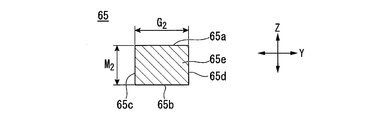
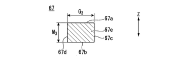
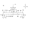
- FIG. 4 is a cross-sectional view taken along the line A 1 -A 2 of one straight line portion shown in FIG. 3 (a cross-sectional view when one straight line portion is cut along a plane orthogonal to the direction in which the one straight line portion extends).
- FIG. 4 is a cross-sectional view in the B 1 -B 2 line direction of the other straight line portion shown in FIG. 3 (cross-sectional view when the other straight line portion is cut by a plane orthogonal to the direction in which the other straight line portion extends).
- FIG. 3 is a cross-sectional view of the first connection portion shown in FIG. 3 taken along the line E 1 -E 2 (a cross-sectional view when the first connection portion is cut along a plane orthogonal to the direction in which the first connection portion extends). is there.
- FIG. 3 is a cross-sectional view in the F 1 -F 2 line direction of the second connection portion shown in FIG.
- FIG. 1 An axis of the rotary shaft body 35 (hereinafter referred to as “axis O”), O 1 is an eccentric axis of the eccentric shaft 36 (hereinafter referred to as “eccentric axis O 1 ”), and the X direction is the first direction. , Z direction indicates the height direction of the scroll compressor 10.
- the scroll compressor 10 includes a housing 11, a suction pipe 13, a discharge pipe 15, a main bearing 17, a sub bearing 19, a rotary shaft 21, an oil supply pump 22, a drive unit 23, and a scroll compressor body 24. And a bush assembly 25 and an Oldham ring 27.
- the housing 11 has a sealed structure, and has a hollow portion therein.
- the housing 11 includes a cylindrical portion 31, a bottom portion 32, and a lid portion 33.
- the cylindrical portion 31 is a cylindrical member and extends in the Z direction. The upper end and the lower end of the cylindrical portion 31 are open ends.
- the bottom part 32 is provided so as to close the lower end of the cylindrical part 31.
- the lid portion 33 is provided so as to close the upper end of the cylindrical portion 31.
- the housing 11 houses a main bearing 17, a sub-bearing 19, a rotating shaft 21, an oil supply pump 22, a drive unit 23, a scroll compressor body 24, a bush assembly 25, and an Oldham ring 27.
- the interior of the housing 11 is partitioned by a scroll compressor body 24 into a suction chamber 11A disposed below the scroll compressor body 24 and a discharge chamber 11B disposed above the scroll compressor body 24. .
- the suction pipe 13 is provided in the middle part of the cylindrical part 31.
- the suction pipe 13 is in communication with a suction chamber 11 ⁇ / b> A formed in the housing 11.
- the suction pipe 13 introduces fluid (for example, refrigerant gas that is a working fluid) from the outside of the housing 11 to the suction chamber 11A.
- the discharge pipe 15 is provided on the lid portion 33.
- the discharge pipe 15 communicates with the discharge chamber 11B.
- the discharge pipe 15 is connected to, for example, a plurality of indoor units (not shown) that are used.
- a fluid compressed by the scroll compressor body 24 (hereinafter referred to as “high pressure fluid”) is discharged to the discharge pipe 15.
- the discharged high-pressure fluid is supplied to the user.
- the main bearing 17 is fixed to the inner wall of the housing 11.
- the main bearing 17 is disposed between the connection position between the suction pipe 13 and the housing 11 and the scroll compressor body 24.
- the main bearing 17 supports one end portion 35A of the rotary shaft main body 35 extending in the direction of the axis O in a rotatable state.
- the rotating shaft 21 has a rotating shaft main body 35 and an eccentric shaft 36.
- the rotating shaft main body 35 has a cylindrical shape.
- the rotating shaft main body 35 has one end 35A disposed on the scroll compressor main body 24 side and the other end 35B disposed on the bottom 32 side.
- the rotary shaft main body 35 is supported by the main bearing 17 and the sub bearing 19 so as to be rotatable around the axis O.
- the eccentric shaft 36 is provided at the end of one end portion 35 ⁇ / b> A of the rotary shaft main body 35.
- the eccentric shaft 36 has an eccentric axis O 1 offset (eccentric) with respect to the axis O as a central axis.
- the eccentric shaft 36 is a cylindrical shaft that is smaller than the outer diameter of the rotary shaft main body 35.
- the eccentric shaft 36 having such a configuration revolves around the axis O 1 when the rotary shaft main body 35 rotates around the axis O.
- the oil pump 22 is provided below the sub bearing 19.
- the oil supply pump 22 supplies lubricating oil to the bearing main bodies constituting the main bearing 17 and the sub bearing 19.
- the drive unit 23 is accommodated in the housing 11.
- the drive unit 23 is disposed so as to surround the outer peripheral surface of the central portion of the rotary shaft main body 35.
- the drive unit 23 rotates the rotary shaft main body 35.
- the scroll compressor body 24 is provided between the main bearing 17 and the discharge chamber 11B.
- the scroll compressor body 24 includes a fixed scroll 41 and a turning scroll 42.
- the fixed scroll 41 is disposed between the orbiting scroll 42 and the discharge chamber 11B.
- the fixed scroll 41 has an end plate 45 and a fixed wrap 46.
- the end plate 45 is a disk-shaped plate material and is fixed to the inner wall of the housing 11.
- the end plate 45 faces the orbiting scroll 42 arranged below the fixed scroll 41.
- the end plate 45 has a discharge port 45A.
- the discharge port 45A is a hole formed so as to penetrate the center of the end plate 45, and extends in the Z direction.
- the discharge port 45A discharges the high-pressure fluid that has been compressed by the scroll compressor body 24 into the discharge chamber 11B.
- the fixed wrap 46 is provided on the surface (lower surface) of the end plate 45 facing the orbiting scroll 42.
- the fixed wrap 46 is erected in the Z direction.
- the fixed wrap 46 is a wall formed in a spiral shape when viewed from the Z direction.
- a plate-like member wound around the center of the end plate 45 can be used.
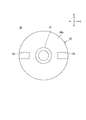
- the orbiting scroll 42 will be described with reference to FIGS. 1 and 2.
- the Y direction is the second direction, which is a direction orthogonal to the X direction and the Z direction shown in FIG.
- the orbiting scroll 42 is disposed between the fixed scroll 41 and the main bearing 17.
- the orbiting scroll 42 includes an end plate 48, an orbiting wrap 49, a boss portion 51, and a groove 53.
- the end plate 48 is a disk-shaped plate material and faces the end plate 45 in the Z direction.
- the turning wrap 49 is provided on the surface of the end plate 48 facing the end plate 45.
- the turning lap 49 is erected in the Z direction.
- the swirl wrap 49 is a wall formed in a spiral shape when viewed from the Z direction.
- a plate-like member wound around the center of the end plate 48 can be used.
- the revolving wrap 49 configured as described above is arranged so as to mesh with the fixed wrap 46 described above.
- a compression chamber 24 ⁇ / b> A that is a space for compressing fluid is defined between the swirl wrap 49 and the fixed wrap 46.
- the volume of the compression chamber 24 ⁇ / b> A changes due to the turning lap 49 turning with respect to the fixed scroll 41. Thereby, the fluid (refrigerant) in the compression chamber 24A is compressed.
- the boss 51 is provided at the center of the surface 48 a of the end plate 48 that faces the rotating shaft 21.
- the boss portion 51 is a cylindrical member and protrudes in the direction toward the sub bearing 19.
- the boss portion 51 is disposed so as to surround the outer periphery of the eccentric shaft 36.
- a bearing is provided on the inner peripheral surface of the boss portion 51. Lubricating oil is supplied to the bearing from an oil supply pump 22.
- Two grooves 53 are formed on the surface 48 a side of the end plate 48.
- the two grooves 53 are opposed to each other with the boss portion 51 interposed therebetween in a plan view.
- the two grooves 53 extend to the outer periphery of the end plate 48.
- the bush assembly 25 is provided between the orbiting scroll 42 and the rotary shaft 21.
- the bush assembly 25 connects the orbiting scroll 42 and the rotary shaft 21.
- the bush assembly 25 includes a bush 25 ⁇ / b> A provided between the eccentric shaft 36 and the boss portion 51.
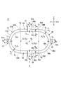
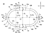
- C 1 is an intermediate position of the straight line connecting the one end 65A of the one end 64A and the straight portion 65 of the straight portion 64 (hereinafter, referred to as "intermediate position C 1")
- C 2 is a semi-circular shape
- the center positions (hereinafter referred to as “center position C 2 ”) of the inner peripheral surface 67 c and the outer peripheral surface 67 d of the first connecting portion 67, C 3 are the other end 64 B of the linear portion 64 and the other end of the linear portion 65.
- intermediate position C 3 An intermediate position of a straight line connecting to the end 65B (hereinafter referred to as “intermediate position C 3 ”), C 4 is a center position (hereinafter referred to as an inner peripheral surface 68c and an outer peripheral surface 68d of the second connecting portion 68 having a semicircular shape. , “Center position C 4 ”).
- O 2 is an axis of the Oldham ring main body 55 (hereinafter referred to as “axis O 2 ”)
- G 1 is a width of the linear portion 64 in the direction in which the linear portion 64 extends (hereinafter referred to as “width G 1 ”).
- G 2 is the width of the straight portion 65 in the direction in which the straight portion 65 extends (hereinafter referred to as “width G 2 ”)
- G 3 is the width of the first connection portion 67 in the direction in which the first connection portion 67 extends
- “width G 3 ” and G 4 indicate the width of the second connection portion 68 in the direction in which the second connection portion 68 extends (hereinafter referred to as “width G 4 ”).
- W 1 is the width of the first Oldham key 57 in the X direction (hereinafter referred to as “width W 1 ”)
- W 2 is the width of the first Oldham key 58 in the X direction (hereinafter referred to as “width W 2 ”).
- W 3 is the width of the second Oldham key 61 in the Y direction (hereinafter referred to as “width W 3 ”)
- W 4 is the width of the second Oldham key 62 in the Y direction (hereinafter referred to as “width W 4 ”). ) Respectively.
- H 1 is the height of the first Oldham key 57 in the axis O 2 direction (Z direction) (hereinafter referred to as “height H 1 ”)
- H 2 is in the axis O 2 direction (Z direction).
- the height of the first Oldham key 58 (hereinafter referred to as “height H 2 ”)
- H 3 is the height of the second Oldham key 61 in the axis O 2 direction (Z direction) (hereinafter referred to as “height H 3 ”).
- H 4 respectively indicate the height of the second Oldham key 62 in the axis O 2 direction (Z direction) (hereinafter referred to as “height H 4 ”).
- FIG. 3 the same components as those in the structure shown in FIG. 3 to 9, the same reference numerals are given to the same components. 10, the same components as those shown in FIGS. 2 and 3 are denoted by the same reference numerals.
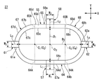
- the Oldham ring 27 is a member for suppressing the rotation (rotation about the eccentric axis O 1 ) of the orbiting scroll 42, and is provided between the orbiting scroll 42 and the main bearing 17.
- the Oldham ring 27 includes an Oldham ring main body 55, first Oldham keys 57 and 58, and second Oldham keys 61 and 62.
- the Oldham ring main body 55 includes a pair of straight portions 64 and 65, a first connection portion 67, and a second connection portion 68.
- Each of the straight portions 64 and 65 extends in the X direction (first direction).
- the straight portions 64 and 65 are arranged to face each other in a state of being separated from each other in the Y direction (second direction).
- the straight portion 64 has one end 64A and the other end 64B arranged in the X direction, surfaces 64a and 64b, an inner surface 64c, and an outer surface 64d.
- Surface 64a is a surface arranged on one side of the axis O 2, and faces a part of the orbiting scroll 42 in the Z direction.
- Surface 64b is a surface arranged on the other side of the axis O 2, it is arranged on the opposite side of the surface 64a.
- the inner surface 64c is a surface facing the linear portion 65 in the Y direction.
- the outer surface 64d is a surface disposed on the opposite side of the inner surface 64c.
- a cut surface 64e of the straight portion 64 formed by cutting the straight portion 64 at a surface (virtual surface) orthogonal to the X direction is a rectangle.
- the width of the linear portion 64 in the Y direction is the width G 1.
- the thickness of the straight portion 64 in the Z direction is the thickness M 1.
- the straight portion 65 has one end 65A and the other end 65B arranged in the X direction, surfaces 65a and 65b, an inner surface 65c, and an outer surface 65d.
- Surface 65a is a surface arranged on one side of the axis O 2, and faces a part of the orbiting scroll 42 in the Z direction.
- Surface 65b is a surface arranged on the other side of the axis O 2, it is arranged on the opposite side of the surface 65a.
- the inner surface 65c is a surface facing the linear portion 64 in the Y direction.
- the outer surface 65d is a surface disposed on the opposite side of the inner surface 65c.
- a cut surface 65e of the straight line portion 65 formed by cutting the straight line portion 65 along a surface (virtual surface) orthogonal to the X direction is rectangular.
- the width G 2 of the straight line portion 65 in the Y direction is configured to be equal to the width G 1 of the straight line portion 64.
- the thickness M 2 of the straight portion 65 in the Z direction is configured to be equal to the thickness M 1 of the straight portion 64.
- the first connecting portion 67 connects one end 64A of the straight portion 64 and one end 65A of the straight portion 65.
- the first connection portion 67 is a member having an arc shape.
- the first connecting portion 67 has surfaces 67a and 67b, an inner peripheral surface 67c, and an outer peripheral surface 67d.
- Surface 67a is a surface arranged on one side of the axis O 2.
- Surface 67b is a surface arranged on the other side of the axis O 2, it is arranged on the opposite side of the surface 67a.
- the inner peripheral surface 67c is a surface connected to the inner surfaces 64c and 65c of the linear portions 64 and 65.
- the inner peripheral surface 67c is a semicircular shape when viewed from the axial O 2 direction.
- the outer peripheral surface 67d is a surface connected to the outer surfaces 64d and 65d of the linear portions 64 and 65.
- the outer circumferential surface 67d is a semicircular shape when viewed from the axial O 2 direction. Center position C 2 of the inner circumferential surface 67c and the outer peripheral surface 67d of the first connecting portion 67, consistent with the intermediate position C 1 of a line connecting the one end 64A and the one end 65A of the linear portion 65 of the straight portion 64 Is configured to do.
- the pair of linear The inner surfaces 64c and 65c of the portions 64 and 65 and the inner peripheral surface 67c of the first connection portion 67 can be connected with a smooth surface, and the outer surfaces 64d and 65d of the pair of straight portions 64 and 65 and the first It is possible to connect the outer peripheral surface 67d of the first connecting portion 67 with a smooth surface.
- a cut surface 67e of the first connection portion 67 formed by cutting the first connection portion 67 at a surface (virtual surface) orthogonal to the direction in which the first connection portion 67 extends is rectangular. Yes.
- the width G 3 of the straight portion 64 orthogonal to the direction in which the first connection portion 67 extends is configured to be equal to the widths G 1 and G 2 of the straight portions 64 and 65.
- the thickness M 3 of the first connection portion 67 in the Z direction is configured to be equal to the thicknesses M 1 and M 2 of the straight portions 64 and 65.
- the second connection portion 68 connects the other end 64B of the straight portion 64 and the other end 65B of the straight portion 65.
- the second connection portion 68 is a member having an arc shape.
- the second connection portion 68 has surfaces 68a and 68b, an inner peripheral surface 68c, and an outer peripheral surface 68d.
- Surface 68a is a surface arranged on one side of the axis O 2.
- Surface 68b is a surface arranged on the other side of the axis O 2, it is arranged on the opposite side of the surface 68a.
- the inner peripheral surface 68c is a surface connected to the inner surfaces 64c and 65c of the straight portions 64 and 65.
- the inner peripheral surface 68c is a semicircular shape when viewed from the axial O 2 direction.
- the outer peripheral surface 68d is a surface connected to the outer surfaces 64d and 65d of the straight portions 64 and 65.
- the outer circumferential surface 68d is a semicircular shape when viewed from the axial O 2 direction. Center position C 4 of the inner peripheral surface 68c and the outer peripheral surface 68d of the second connecting portion 68, consistent with the linear intermediate positions C 3 connecting the other end 65B of the other end 64B and the straight portion 65 of the straight portion 64 Is configured to do.
- the cut surface 68e of the second connection portion 68 formed by cutting the second connection portion 68 at a surface (virtual surface) orthogonal to the direction in which the second connection portion 68 extends is rectangular. Yes.
- the width G 4 of the straight portion 64 orthogonal to the direction in which the second connection portion 68 extends is equal to the widths G 1 and G 2 of the straight portions 64 and 65 and the width G 3 of the first connection portion 67. It is configured.
- the thickness M 4 of the second connecting portion 68 in the Z direction is configured such that the thickness M 3 equals the thickness M 1, M 2 and the first connecting portion 67 of the straight portion 64 and 65 Yes.
- the areas of the cut surfaces 64e and 65e of the straight portions 64 and 65, the first area of the cut surface 67e of the first connection portion 67, and the cut surface 68e of the second connection portion 68. are configured to have the same second area.
- the first Oldham key 57 is provided on the surface 64 a located at the center of the linear portion 64.
- the first Oldham key 57 is inserted into one of the two grooves 53 of the orbiting scroll 42.
- the first Oldham key 57 is disposed in the circumferential direction of the Oldham ring main body 55 and has a first pressure receiving surface 57a that receives a load.
- the first Oldham key 57 protrudes outside the outer surface 64 d of the linear portion 64.
- the length L 1 of the first Oldham key 57 in the Y direction is configured to be larger than the width G 1 of the linear portion 64.
- the first Oldham key 58 is provided on a surface 65 a located at the center of the linear portion 65.
- the first Oldham key 58 faces the first Oldham key 57 in the Y direction.
- the first Oldham key 58 is inserted into the other groove 53 of the two grooves 53 of the orbiting scroll 42.
- the first Oldham key 58 is disposed in the circumferential direction of the Oldham ring main body 55 and has a first pressure receiving surface 58a that receives a load.
- the first Oldham key 58 protrudes outside the outer surface 65 d of the linear portion 65.
- the length L 2 of the first Oldham key 58 in the Y direction is configured to be larger than the width G 2 of the linear portion 65.
- the width W 2 of the first Oldham key 58 in the X direction is configured to be equal to the width W 1 of the first Oldham key 57.
- the height H 2 of the first Oldham key 58 is configured to be equal to the height H 1 of the first Oldham key 57.
- the lengths L 1 and L 2 of the first Oldham keys 57 and 58 are configured to be longer than the lengths L 3 and L 4 of the second Oldham keys 61 and 62.
- the second Oldham key 61 is provided on a surface 67 a located at the center of the first connection portion 67.
- the second Oldham key 61 is inserted into a groove (not shown) formed in the fixed scroll 41.
- the second Oldham key 61 is disposed in the circumferential direction of the Oldham ring main body 55 and has a second pressure receiving surface 61 a that receives a load.
- the second Oldham key 61 protrudes outside the outer peripheral surface 67d of the first connection portion 67 in the X direction.
- the length L 3 of the second Oldham key 61 in the X direction is configured to be larger than the width G 3 of the first connection portion 67.
- the width W 3 of the second Oldham key 61 in the Y direction is configured to be equal to the widths W 1 and W 2 of the first Oldham keys 57 and 58.
- the height H 3 of the second Oldham key 61 is configured to be equal to the heights H 1 and H 2 of the first Oldham keys 57 and 58.
- the second Oldham key 62 is provided on a surface 68 a located at the center of the second connection portion 68.
- the second Oldham key 62 is opposed to the second Oldham key 61 in the X direction.
- the second Oldham key 62 is inserted into a groove (not shown) formed in the fixed scroll 41.
- the second Oldham key 62 is disposed in the circumferential direction of the Oldham ring main body 55 and has a second pressure receiving surface 62a that receives a load.
- the second Oldham key 62 protrudes outside the outer peripheral surface 68 d of the second connection portion 68.
- the length L 4 of the second Oldham key 62 in the Y direction is configured to be larger than the width G 4 of the second connection portion 68.
- the width W 4 of the second Oldham key 62 in the Y direction is configured to be equal to the widths W 1 and W 2 of the first Oldham keys 57 and 58 and the width W 3 of the second Oldham key 61.
- the height H 4 of the second Oldham key 62 is configured to be equal to the heights H 1 and H 2 of the first Oldham keys 57 and 58 and the height H 3 of the second Oldham key 62.
- the first and second Oldham keys 57, 58, 61, 62 are Oldham keys having different lengths and equal widths and heights.
- the first distance D 1 between the pair of straight portions 64 and 65 in the Y direction is the first distance between the first connection portion 67 and the second connection portion 68 in the X direction.
- the distance D 2 is shorter than 2 .
- the first distance D 1 between the pair of straight portions 64 and 65 in the Y direction is greater than the second distance D 2 between the first connection portion 67 and the second connection portion 68 in the X direction.
- the first pressure receiving surface 57a, 58a will be subject to greater load than the load of the second pressure receiving surface 61a, 62a is subjected .
- the lengths L 1 and L 2 of the first Oldham keys 57 and 58 are configured to be longer than the lengths L 3 and L 4 of the second Oldham keys 61 and 62.
- the lengths L 1 and L 2 of the first Oldham keys 57 and 58 are made longer than the lengths L 3 and L 4 of the second Oldham keys 61 and 62, whereby the second pressure receiving surfaces 61a and 62a. It is possible to make the area of the first pressure receiving surfaces 57a, 58a larger than the area of. Thereby, the surface pressure (surface pressure resulting from the load) of the first pressure receiving surfaces 57a and 58a receiving a load larger than the load received by the second pressure receiving surfaces 61a and 62a is reduced, and the first Oldham key 57 Damage can be suppressed.
- the Oldham ring 27 of the first embodiment as described above, the first distance D 1 between the pair of linear portions 64 and 65 first Oldham key 57 and 58 are arranged, a second Oldham key 61 by is configured as the first connecting portion 67 and the second Oldham key 62 disposed is shorter than the second distance D 2 between the second connecting part 68 disposed, Oldham ring 27 and
- the turning scroll 42 can be reduced in size and weight.
- the lengths L 1 and L 2 of the first Oldham keys 57 and 58 are made longer than the lengths L 3 and L 4 of the second Oldham keys 61 and 62, so that the second Oldham keys 61 and 62 have a second length.
- the area of the first pressure receiving surfaces 57a, 58a of the first Oldham keys 57, 58 can be made larger than the area of the pressure receiving surfaces 61a, 62a.
- the surface pressure received by the first pressure receiving surfaces 57a and 58a due to the load can be reduced, so that the damage to the first Oldham keys 57 and 58 can be suppressed.
- the Oldham ring 27 and the orbiting scroll 42 are formed between the Oldham ring 27 and the orbiting scroll 42 and the inner surface of the housing 11. It is possible to increase the gap. Thereby, the fluid can be easily moved in the Z direction in which the rotation shaft 21 extends.
- the thicknesses M 1 and M 2 of the straight portions 64 and 65 and the thicknesses M 3 and M 4 of the first and second connection portions 67 and 68 are equal, and The case where the widths G 1 and G 2 of the straight portions 64 and 65 are equal to the widths G 3 and G 4 of the first and second connection portions 67 and 68 has been described as an example.
- the thicknesses M 1 and M 2 of the 65 are made thicker than the thicknesses M 3 and M 4 of the first and second connection portions 67 and 68, or the widths G 1 and G 2 of the straight portions 64 and 65 are made.
- the cross-sectional areas of the cut surfaces 64e and 65e of the straight portions 64 and 65 are the same as the first cross-sectional area of the cut surface 67e of the first connection portion 67 and the second cross-section 68e of the second connection portion 68.
- the strength of the straight portions 64 and 65 can be improved, and damage to the straight portions 64 and 65 can be suppressed.
- L 5 is the length of the first Oldham key 76 in the Y direction (hereinafter referred to as “length L 1 ”)
- L 6 is the length of the first Oldham key 77 in the Y direction (hereinafter referred to as “length”).
- L 2 the same components as those in the structure shown in FIG.
- H 5 is the height of the first Oldham key 76 in the axis O 2 direction (Z direction)
- H 6 is the first in the axis O 2 direction (Z direction).
- the same components as those shown in FIGS. 4 and 11 are denoted by the same reference numerals.
- the Oldham ring 75 is configured in the same manner as the Oldham ring 27 except that the Oldham ring 75 includes first Oldham keys 76 and 77 instead of the first Oldham keys 57 and 58 constituting the Oldham ring 27 of the first embodiment. .
- the first Oldham key 76 has a length L 5 shorter than the length L 1 of the first Oldham key 57 and a height H 5 higher than the height H 1 of the first Oldham key 57. Is configured in the same manner as the first Oldham key 57.
- the length L 5 of the first Oldham key 76 for example, can be the same length as the length L 3, L 4 of the second Oldham key 61.
- the first Oldham key 76 is disposed in the circumferential direction of the Oldham ring main body 55 and has a first pressure receiving surface 76a having a larger area than the second pressure receiving surfaces 61a and 62a.
- the first Oldham key 77 except that the shorter the length L 6 than the length L 2 of the first Oldham key 58, and is the height H 6 higher than the height H 2 of the first Oldham key 58 Is configured in the same manner as the first Oldham key 58.
- the length L 6 of the first Oldham key 77 can be, for example, the same length as the lengths L 3 and L 4 of the second Oldham keys 61 and 62 and the length L 5 of the first Oldham key 76. It is.
- the first Oldham key 77 is disposed in the circumferential direction of the Oldham ring main body 55, and has a first pressure receiving surface 77a having a larger area than the second pressure receiving surfaces 61a and 62a.
- the lengths L 5 and L 6 of the first Oldham keys 76 and 77 are not made longer than the lengths L 3 and L 4 of the second Oldham keys 61 and 62.
- the size of the Oldham ring 75 is increased in the Y direction by making the heights H 5 and H 6 of the first Oldham keys 76 and 77 higher than the heights H 3 and H 4 of the second Oldham keys 61 and 62.
- the area of the first pressure receiving surfaces 76a and 77a is made larger than the area of the second pressure receiving surfaces 61a and 62a to reduce the surface pressure received by the first pressure receiving surfaces 76a and 77a due to the load. It becomes possible. As a result, it is possible to reduce the size and weight of the Oldham ring 75 and the orbiting scroll while suppressing damage to the first Oldham keys 76 and 77.
- the Oldham ring 80 is configured in the same manner as the Oldham ring 27 except that it has first Oldham keys 81 and 82 instead of the first Oldham keys 76 and 77 constituting the Oldham ring 75 of the second embodiment. .
- the first Oldham key 82 has the same configuration as the first Oldham key 77 except that the first Oldham key 82 has a width W 6 wider than the width W 2 of the first Oldham key 77.
- the first Oldham key 82 is arranged in the circumferential direction of the Oldham ring main body 55 and has a first pressure receiving surface 82a having a larger area than the second pressure receiving surfaces 61a and 62a.
- the lengths L 5 and L 6 of the first Oldham keys 81 and 82 are longer than the lengths L 3 and L 4 of the second Oldham keys 61 and 62.
- the Oldham ring 80 is not enlarged in the Y direction.
- the area of the first pressure receiving surfaces 81a and 82a larger than the area of the second pressure receiving surfaces 61a and 62a, it is possible to reduce the surface pressure received by the first pressure receiving surfaces 81a and 82a due to the load. Become. As a result, it is possible to reduce the size and weight of the Oldham ring 80 and the orbiting scroll while suppressing damage to the first Oldham keys 81 and 82.
- L 7 is the length of the first Oldham key 86 in the Y direction (hereinafter referred to as “length L 7 ”)
- L 8 is the length of the first Oldham key 87 in the Y direction (hereinafter referred to as “length”). L 7 ”).
- FIG. 13 the same components as those in the structure shown in FIG.
- H 7 is the height of the first Oldham key 86 in the direction of the axis O 2 (hereinafter referred to as “height H 7 ”)
- H 8 is the height of the first Oldham key 87 in the direction of the axis O 2 (hereinafter referred to as “height H 7 ”).
- Height H 8 is the same components as those shown in FIGS. 4 and 14 are denoted by the same reference numerals.
- the Oldham ring 85 is configured in the same manner as the Oldham ring 27 except that it has first Oldham keys 86 and 87 instead of the first Oldham keys 57 and 58 constituting the Oldham ring 27 of the first embodiment. .
- the first Oldham key 86 has a length L 7 in the Y direction that is the same as the width G 1 of the straight portion 64 and the height H 7 so that it does not protrude outside the outer surface 64 d of the straight portion 64.
- the configuration is the same as that of the first Oldham key 57 except that it is configured to be higher than the height H 1 of the Oldham key 57 and the heights H 3 and H 4 of the second Oldham keys 61 and 62. ing.
- the first Oldham key 86 has a first pressure receiving surface 86 a arranged in the circumferential direction of the Oldham ring main body 55.
- the first Oldham key 87 so as not to protrude outside the outer surface 65d of the straight portion 65, Y-direction length L 8 is as large as the width G 2 of the linear portion 65, and the height H 8 is first
- the configuration is the same as that of the first Oldham key 58 except that it is configured to be higher than the height H 2 of the Oldham key 58 and the heights H 3 and H 4 of the second Oldham keys 61 and 62. ing.
- the first Oldham key 87 has a first pressure receiving surface 87 a disposed in the circumferential direction of the Oldham ring main body 55.
- the length L of the first Oldham keys 86, 87 is set so that the first Oldham keys 86, 87 do not protrude outside the outer surfaces 64d, 65d of the straight portions 64, 65. 7 and L 8 are made the same size as the widths G 1 and G 2 of the straight portions 64 and 65, and the heights H 1 and H 2 of the first Oldham keys 86 and 87 are set to the heights of the second Oldham keys 61 and 62.
- the area of the first pressure receiving surfaces 86 a and 87 a is larger than the area of the second pressure receiving surfaces 61 a and 62 a without increasing the size of the Oldham ring 85 in the Y direction.
- the surface pressure received by the first pressure receiving surfaces 81a and 82a due to the load can be reduced.
- the lengths L 1 and L 2 of the first Oldham keys 57 and 58 are made longer than the lengths L 3 and L 4 of the second Oldham keys 61 and 62, so that the second The areas of the first pressure receiving surfaces 57a, 58a are made larger than the areas of the pressure receiving surfaces 61a, 62a, and in the second embodiment, the heights H 5 , H 6 of the first Oldham keys 76, 77 are set to the second Oldham keys.
- the areas of the first pressure receiving surfaces 76a and 77a are made larger than the areas of the second pressure receiving surfaces 61a and 62a, and in the third embodiment, By making the widths W 5 and W 6 of the first Oldham keys 81 and 82 wider than the widths W 3 and W 4 of the second Oldham keys 61 and 62, the first Oldham keys 81 and 82 are larger than the areas of the second pressure receiving surfaces 61 a and 62 a.
- Et three forms (length, height, width) by combining the appropriate area of the first pressure receiving surface of the first Oldham key may be made larger than the area of the second pressure receiving surface.
- Oldham rings 27, 75, 80, 85 are arranged below the orbiting scroll 42 as shown in FIG. 1
- Oldham rings 27, 75, 80, and 85 may be disposed between the fixed scroll 41 and the orbiting scroll 42.
- the second Oldham keys 61 and 62 of the Oldham rings 27, 75, 80 and 85 are inserted into grooves (not shown) formed in the fixed scroll 41.
- first and second connection portions 67 and 68 are arc-shaped has been described as an example, but the shape of the first and second connection portions 67 and 68 is described. May have a shape other than the arc shape.
- each of the first and second connection portions 67 and 68 may be formed by one straight portion, or may be formed by connecting a plurality of straight portions extending in directions intersecting each other. Also good.
- the present invention is applicable to Oldham rings and scroll compressors.
Landscapes
- Engineering & Computer Science (AREA)
- Mechanical Engineering (AREA)
- General Engineering & Computer Science (AREA)
- Rotary Pumps (AREA)
Abstract
Description
本願は、2018年4月25日に、日本に出願された特願2018-084536号に基づき優先権を主張し、その内容をここに援用する。
特許文献1に開示されたオルダムリングは、一対の直線部と、一対の直線部の一方の端を接続する第1の円弧部と、一対の直線部の他方の端を接続する第2の円弧部と、一対の直線部にそれぞれ設けられ、旋回スクロールの端板の溝に挿入される第1のオルダムキーと、第1及び第2の円弧部にそれぞれ設けられた第2のオルダムキーと、を有する。
第2のオルダムキーは、オルダムリングの軸線方向他方側に配置されている。第2のオルダムキーは、オルダムリングの周方向に配置された第2の受圧面を有する。
オルダムリング及び旋回スクロールの小型化を図る観点から、一対の直線部間の距離は、第1の円弧部と第2の円弧部との距離よりも小さくなるように構成されている。
これにより、第1のオルダムキーの第1の受圧面には、第2のオルダムキーの第2の受圧面が受ける荷重よりも大きな荷重(旋回荷重や圧縮荷重等)が作用し、第1のオルダムキーが損傷する可能性があった。
つまり、本発明によれば、第1のオルダムキーが損傷することを抑制した上で、オルダムリング及び旋回スクロールの小型化及び軽量化を図ることができる。
そこで、直線部の断面積を、第1の接続部の第1の断面積、及び第2の接続部の第2の断面積よりも大きくすることで、直線部の強度が向上し、直線部の損傷を抑制することができる。
これにより、一対の直線部の内面と第1の接続部の内周面との境界部分、及び一対の直線部の外面と第1の接続部の外周面との境界部分に応力が集中することを抑制できる。
これにより、一対の接続部の内面と第2の接続部の内周面との境界部分、及び一対の接続部の外面と第2の接続部の外周面との境界部分に応力が集中することを抑制できる。
また、直線部の外面から外側に突出しないように第1のオルダムキーを配置させることで、第2の方向におけるオルダムリング及び旋回スクロールのサイズをさらに小さくすることができる。
これにより、荷重により第1の受圧面が受ける面圧を低減させて、第1のオルダムキーが損傷することを抑制できる。
図1を参照して、第1の実施形態のスクロール圧縮機10について説明する。
図1において、Oは回転軸本体35の軸線(以下、「軸線O」という)、O1は偏心軸36の偏心軸線(以下、「偏心軸線O1」という)、X方向は第1の方向、Z方向はスクロール圧縮機10の高さ方向をそれぞれ示している。
筒状部31は、円筒形状とされた部材であり、Z方向に延びている。筒状部31の上端及び下端は、開放端とされている。
底部32は、筒状部31の下端を塞ぐように設けられている。蓋部33は、筒状部31の上端を塞ぐように設けられている。
ハウジング11の内部は、スクロール圧縮機本体24により、スクロール圧縮機本体24の下方に配置された吸入室11Aと、スクロール圧縮機本体24の上方に配置された吐出室11Bと、に区画されている。
吐出配管15には、スクロール圧縮機本体24により圧縮された流体(以下、「高圧流体」という)が排出される。そして、排出された高圧流体は、使用先に供給される。
メイン軸受17は、軸線O方向に延在する回転軸本体35の一方の端部35Aを回転可能な状態で支持している。
回転軸本体35は、メイン軸受17及びサブ軸受19により軸線O周りに回転可能な状態で支持されている。
このような構成とされた偏心軸36は、軸線O回りに回転軸本体35が回転すると、軸線O1回りに公転する。
端板45は、吐出口45Aを有する。吐出口45Aは、端板45の中央を貫通するように形成された穴であり、Z方向に延在している。吐出口45Aは、スクロール圧縮機本体24による圧縮が完了した高圧流体を吐出室11Bに吐出させる。
旋回ラップ49は、端板45と対向する端板48の面に設けられている。旋回ラップ49は、Z方向に立設されている。旋回ラップ49は、Z方向から見て渦巻き状に形成された壁体である。旋回ラップ49としては、例えば、端板48の中心回りに巻回された板状の部材を用いることが可能である。
なお、ボス部51の内周面には、軸受が設けられている。該軸受には、給油ポンプ22から潤滑油が供給される。
図3において、C1は直線部64の一方の端64Aと直線部65の一方の端65Aとを結ぶ直線の中間位置(以下、「中間位置C1」という)、C2は半円形状とされた第1の接続部67の内周面67c及び外周面67dの中心位置(以下、「中心位置C2」という)、C3は直線部64の他方の端64Bと直線部65の他方の端65Bとを結ぶ直線の中間位置(以下、「中間位置C3」という)、C4は半円形状とされた第2の接続部68の内周面68c及び外周面68dの中心位置(以下、「中心位置C4」という)をそれぞれ示している。
図3において、図1に示す構造体と同一構成部分には、同一符号を付す。図3~図9において、同一構成部分には、同一符号を付す。図10において、図2及び図3に示す構造体と同一構成部分には、同一符号を付す。
オルダムリング27は、オルダムリング本体55と、第1のオルダムキー57,58と、第2のオルダムキー61,62と、を有する。
直線部64,65は、それぞれX方向(第1の方向)に延びている。直線部64,65は、Y方向(第2の方向)において互いに離れた状態で対向配置されている。
面64aは、軸線O2の一方側に配置された面であり、Z方向において一部が旋回スクロール42と対向している。面64bは、軸線O2の他方側に配置された面であり、面64aの反対側に配置されている。
内面64cは、Y方向において直線部65と対向する面である。外面64dは、内面64cの反対側に配置された面である。
面65aは、軸線O2の一方側に配置された面であり、Z方向において一部が旋回スクロール42と対向している。面65bは、軸線O2の他方側に配置された面であり、面65aの反対側に配置されている。
内面65cは、Y方向において直線部64と対向する面である。外面65dは、内面65cの反対側に配置された面である。
また、Z方向における直線部65の厚さM2は、直線部64の厚さM1と等しくなるように構成されている。
このように、第1の接続部67を円弧形状とすることで、第1の接続部67を直線形状とした場合と比較して、第1の接続部67が受ける応力を小さくすることができる。
面67aは、軸線O2の一方側に配置された面である。面67bは、軸線O2の他方側に配置された面であり、面67aの反対側に配置されている。
外周面67dは、直線部64,65の外面64d,65dと接続された面である。外周面67dは、軸線O2方向から見て半円形状とされている。
第1の接続部67の内周面67c及び外周面67dの中心位置C2は、直線部64の一方の端64Aと直線部65の一方の端65Aとを結ぶ直線の中間位置C1と一致するように構成されている。
これにより、一対の直線部64,65の内面64c,65cと第1の接続部67の内周面67cとの境界部分、及び一対の直線部64,65の外面64d,65dと第1の接続部67の外周面67dとの境界部分に応力が集中することを抑制できる。
第1の接続部67が延びる方向に対して直交する直線部64の幅G3は、直線部64,65の幅G1,G2と等しくなるように構成されている。
また、Z方向における第1の接続部67の厚さM3は、直線部64,65の厚さM1,M2と等しくなるように構成されている。
このように、第2の接続部68を円弧形状とすることで、第2の接続部68を直線形状とした場合と比較して、第2の接続部68が受ける応力を小さくすることができる。
面68aは、軸線O2の一方側に配置された面である。面68bは、軸線O2の他方側に配置された面であり、面68aの反対側に配置されている。
外周面68dは、直線部64,65の外面64d,65dと接続された面である。外周面68dは、軸線O2方向から見て半円形状とされている。
第2の接続部68の内周面68c及び外周面68dの中心位置C4は、直線部64の他方の端64Bと直線部65の他方の端65Bとを結ぶ直線の中間位置C3と一致するように構成されている。
第2の接続部68が延びる方向に対して直交する直線部64の幅G4は、直線部64,65の幅G1,G2及び第1の接続部67の幅G3と等しくなるように構成されている。
また、Z方向における第2の接続部68の厚さM4は、直線部64,65の厚さM1,M2及び第1の接続部67の厚さM3等しくなるように構成されている。
第1のオルダムキー57は、オルダムリング本体55の周方向に配置され、荷重を受ける第1の受圧面57aを有する。
第1のオルダムキー57は、直線部64の外面64dの外側に突出している。Y方向における第1のオルダムキー57の長さL1は、直線部64の幅G1よりも大きくなるように構成されている。
第1のオルダムキー58は、オルダムリング本体55の周方向に配置され、荷重を受ける第1の受圧面58aを有する。
X方向における第1のオルダムキー58の幅W2は、第1のオルダムキー57の幅W1と等しくなるように構成されている。また、第1のオルダムキー58の高さH2は、第1のオルダムキー57の高さH1と等しくなるように構成されている。
第1のオルダムキー57,58の長さL1,L2は、第2のオルダムキー61,62の長さL3,L4よりも長くなるように構成されている。
第2のオルダムキー61は、オルダムリング本体55の周方向に配置され、荷重を受ける第2の受圧面61aを有する。
Y方向における第2のオルダムキー61の幅W3は、第1のオルダムキー57,58の幅W1,W2と等しくなるように構成されている。また、第2のオルダムキー61の高さH3は、第1のオルダムキー57,58の高さH1,H2と等しくなるように構成されている。
第2のオルダムキー62は、固定スクロール41に形成された溝(図示せず)に挿入される。第2のオルダムキー62は、オルダムリング本体55の周方向に配置され、荷重を受ける第2の受圧面62aを有する。
Y方向における第2のオルダムキー62の幅W4は、第1のオルダムキー57,58の幅W1,W2、及び第2のオルダムキー61の幅W3と等しくなるように構成されている。
また、第2のオルダムキー62の高さH4は、第1のオルダムキー57,58の高さH1,H2、及び第2のオルダムキー62の高さH3と等しくなるように構成されている。
つまり、第1及び第2のオルダムキー57,58,61,62は、長さが異なり、幅及び高さが等しいオルダムキーである。
しかしながら、上述したように、第1のオルダムキー57,58の長さL1,L2は、第2のオルダムキー61,62の長さL3,L4よりも長くなるように構成されている。
これにより、第2の受圧面61a,62aが受ける荷重よりも大きな荷重を受ける第1の受圧面57a,58aの面圧(荷重に起因する面圧)を低減させて、第1のオルダムキー57の損傷を抑制することができる。
これにより、荷重に起因して第1の受圧面57a,58aが受ける面圧を低減することが可能となるので、第1のオルダムキー57,58の損傷を抑制することができる。
図11及び図12を参照して、第2の実施形態のオルダムリング75について説明する。
図11において、L5はY方向における第1のオルダムキー76の長さ(以下、「長さL1」という)、L6はY方向における第1のオルダムキー77の長さ(以下、「長さL2」という)をそれぞれ示している。図11において、図3に示す構造体と同一構成部分には同一符号を付す。
図12において、H5は軸線O2方向(Z方向)における第1のオルダムキー76の高さ(以下、「高さH5」という)、H6は軸線O2方向(Z方向)における第1のオルダムキー77の高さ(以下、「高さH6」という)をそれぞれ示している。図12において、図4及び図11に示す構造体と同一構成部分には、同一符号を付す。
第1のオルダムキー76の長さL5は、例えば、第2のオルダムキー61,62の長さL3,L4と同じ長さにすることが可能である。
第1のオルダムキー76は、オルダムリング本体55の周方向に配置され、第2の受圧面61a,62aよりも面積の大きい第1の受圧面76aを有する。
第1のオルダムキー77の長さL6は、例えば、第2のオルダムキー61,62の長さL3,L4、及び第1のオルダムキー76の長さL5と同じ長さにすることが可能である。
第1のオルダムキー77は、オルダムリング本体55の周方向に配置され、第2の受圧面61a,62aよりも面積の大きい第1の受圧面77aを有する。
これにより、第1のオルダムキー76,77の損傷を抑制した上で、オルダムリング75及び旋回スクロールの小型化及び軽量化を図ることができる。
図13を参照して、第3の実施形態のオルダムリング80について説明する。
図13において、W5はX方向における第1のオルダムキー81の幅(以下、「幅W5」という)、W6はX方向における第1のオルダムキー82の長さ(以下、「幅W6」という)をそれぞれ示している。図13において、図11に示す構造体と同一構成部分には同一符号を付す。
第1のオルダムキー81は、オルダムリング本体55の周方向に配置され、第2の受圧面61a,62aよりも面積の大きい第1の受圧面81aを有する。
第1のオルダムキー82は、オルダムリング本体55の周方向に配置され、第2の受圧面61a,62aよりも面積の大きい第1の受圧面82aを有する。
これにより、第1のオルダムキー81,82の損傷を抑制した上で、オルダムリング80及び旋回スクロールの小型化及び軽量化を図ることができる。
図14及び図15を参照して、第4の実施形態のオルダムリング85について説明する。
図14において、L7はY方向における第1のオルダムキー86の長さ(以下、「長さL7」という)、L8はY方向における第1のオルダムキー87の長さ(以下、「長さL7」という)をそれぞれ示している。図13において、図3に示す構造体と同一構成部分には同一符号を付す。
図15において、H7は軸線O2方向における第1のオルダムキー86の高さ(以下、「高さH7」という)、H8は軸線O2方向における第1のオルダムキー87の高さ(以下、「高さH8」という)をそれぞれ示している。図15において、図4及び図14に示す構造体と同一構成部分には同一符号を付す。
第1のオルダムキー86は、オルダムリング本体55の周方向に配置された第1の受圧面86aを有する。
第1のオルダムキー87は、オルダムリング本体55の周方向に配置された第1の受圧面87aを有する。
これにより、第1のオルダムキー86,87の損傷を抑制した上で、オルダムリング85及び旋回スクロールの小型化及び軽量化を図ることができる。
11 ハウジング
11A 吸入室
11B 吐出室
13 吸入配管
15 吐出配管
17 メイン軸受
19 サブ軸受
21 回転軸
22 給油ポンプ
23 駆動部
24 スクロール圧縮機本体
24A 圧縮室
25 ブッシュアセンブリ
25A ブッシュ
27,75,80,85 オルダムリング
31 筒状部
32 底部
33 蓋部
35 回転軸本体
35A 一方の端部
35B 他方の端部
36 偏心軸
41 固定スクロール
42 旋回スクロール
45,48 端板
45A 吐出口
46 固定ラップ
48a,64a,64b,65a,65b,67a,67b,68a,68b 面
49 旋回ラップ
51 ボス部
53 溝
55 オルダムリング本体
57,58,76,77,81,82,86,87 第1のオルダムキー
57a,58a,76a,77a,81a,82a,86a,87a 第1の受圧面
61,62 第2のオルダムキー
61a,62a 第2の受圧面
64,65 直線部
64A,65A 一方の端
64B,65B 他方の端
64c,65c 内面
64d,65d 外面
64e,65e,67e,68e 切断面
67 第1の接続部
67c,68c 内周面
67d,68d 外周面
68 第2の接続部
C1,C3 中間位置
C2,C4 中心位置
D1 第1の距離
D2 第2の距離
G1~G4,W1~W6 幅
H1~H8 高さ
L1~L8 長さ
M1~M4 厚さ
O,O2 軸線
O1 偏心軸線
Claims (11)
- 第1の方向に延び、該第1の方向に対して直交する第2の方向において対向する一対の直線部、前記一対の直線部の一方の端を接続する第1の接続部、前記一対の直線部の他方の端を接続するとともに、前記第1の方向において前記第1の接続部と対向する第2の接続部を有するオルダムリング本体と、
前記第1の方向及び前記第2の方向に対して直交する前記オルダムリング本体の軸線の一方側に配置された前記一対の直線部の面にそれぞれ設けられており、前記オルダムリング本体の周方向に配置され、荷重を受ける第1の受圧面を有する第1のオルダムキーと、
前記軸線の他方側に配置された前記第1の接続部及び前記第2の接続部の面にそれぞれ設けられており、前記オルダムリング本体の周方向に配置され、荷重を受ける第2の受圧面を有する第2のオルダムキーと、
を備え、
前記第2の方向における前記一対の直線部間の第1の距離は、前記第1の方向における前記第1の接続部と前記第2の接続部との間の第2の距離よりも短く、
前記第1の受圧面の面積は、前記第2の受圧面の面積よりも大きいオルダムリング。 - 前記軸線が延びる方向である軸線方向において、前記第1のオルダムキーの高さは、前記第2のオルダムキーの高さよりも高い請求項1記載のオルダムリング。
- 前記第2の方向における前記第1のオルダムキーの長さは、前記第1の方向における前記第2のオルダムキーの長さよりも長い請求項1または2記載のオルダムリング。
- 前記第1の方向における前記第1のオルダムキーの幅は、前記第2の方向における前記第2のオルダムキーの幅よりも広い請求項1から3のうち、いずれか一項記載のオルダムリング。
- 前記第1のオルダムキーは、前記直線部の外面から外側に突出しないように配置されている請求項1から4のうち、いずれか一項記載のオルダムリング。
- 前記第1の接続部及び前記第2の接続部の形状は、それぞれ円弧形状である請求項1から5のうち、いずれか一項記載のオルダムリング。
- 前記第1の方向に対して直交する面で前記直線部を切断することで形成される該直線部の切断面の面積は、前記第1の接続部が延びる方向に対して直交する面で第1の接続部を切断することで形成される前記第1の接続部の切断面の第1の面積、及び前記第2の接続部が延びる方向に対して直交する面で第2の接続部を切断することで形成される前記第2の接続部の切断面の第2の面積よりも大きい請求項6記載のオルダムリング。
- 前記第1の接続部及び前記第2の接続部は、前記一対の直線部の内面と接続され、前記軸線が延びる方向である軸線方向から見て半円形状とされた内周面と、前記一対の直線部の外面と接続され、前記軸線方向から見て半円形状とされた外周面と、を有し、
前記第1の接続部の内周面及び外周面の中心位置と前記第1の接続部と接続される前記一対の直線部の一方の端同士を結ぶ直線の中間位置とを一致させ、
前記第2の接続部の内周面及び外周面の中心位置と前記第2の接続部と接続される前記一対の直線部の他方の端同士を結ぶ直線の中間位置とを一致させる請求項6または7記載のオルダムリング。 - 第1の方向に延び、該第1の方向に対して直交する第2の方向において対向する一対の直線部、前記一対の直線部の一方の端を接続する第1の接続部、前記一対の直線部の他方の端を接続するとともに、前記第1の方向において前記第1の接続部と対向する第2の接続部を有するオルダムリング本体と、
前記第1の方向及び前記第2の方向に対して直交する前記オルダムリング本体の軸線の一方側に配置された前記一対の直線部の面にそれぞれ設けられた第1のオルダムキーと、
前記軸線の他方側に配置された前記第1の接続部及び前記第2の接続部の面にそれぞれ設けられた第2のオルダムキーと、
を備え、
前記第2の方向における前記一対の直線部間の第1の距離は、前記第1の方向における前記第1の接続部と前記第2の接続部との間の第2の距離よりも短く、
前記第1のオルダムキーは、前記直線部の外面から外側に突出しないように配置されているオルダムリング。 - 前記第1のオルダムキーは、前記オルダムリング本体の周方向に配置された第1の受圧面を有しており、
前記第2のオルダムキーは、前記オルダムリング本体の周方向に配置された第2の受圧面を有しており、
前記オルダムリング本体の軸線が延びる方向である軸線方向における前記第1のオルダムキーの高さは、前記軸線方向における前記第2のオルダムキーの高さよりも高い請求項9記載のオルダムリング。 - 流体を圧縮させるスクロール圧縮機であって、
請求項1から10のうち、いずれか一項記載のオルダムリングと、
前記オルダムリング本体の前記軸線が延びる方向に延び、回転する回転軸と、
前記回転軸に設けられ、前記第1のオルダムキーが挿入される溝が形成された端板を含む旋回スクロールと、
前記旋回スクロールと対向して配置され、該旋回スクロールとの間に流体を圧縮する圧縮室を形成する固定スクロールと、
前記オルダムリング、前記回転軸、前記旋回スクロール、及び前記固定スクロールを収容するハウジングと、
を備えるスクロール圧縮機。
Priority Applications (3)
| Application Number | Priority Date | Filing Date | Title |
|---|---|---|---|
| CN201980040411.4A CN112292531B (zh) | 2018-04-25 | 2019-03-27 | 涡旋压缩机 |
| EP19792850.0A EP3786452A4 (en) | 2018-04-25 | 2019-03-27 | OLDHAM RING AND SCREW COMPRESSOR |
| AU2019258375A AU2019258375B2 (en) | 2018-04-25 | 2019-03-27 | Oldham ring and scroll compressor |
Applications Claiming Priority (2)
| Application Number | Priority Date | Filing Date | Title |
|---|---|---|---|
| JP2018-084536 | 2018-04-25 | ||
| JP2018084536A JP7016285B2 (ja) | 2018-04-25 | 2018-04-25 | スクロール圧縮機 |
Publications (1)
| Publication Number | Publication Date |
|---|---|
| WO2019208075A1 true WO2019208075A1 (ja) | 2019-10-31 |
Family
ID=68295123
Family Applications (1)
| Application Number | Title | Priority Date | Filing Date |
|---|---|---|---|
| PCT/JP2019/013204 Ceased WO2019208075A1 (ja) | 2018-04-25 | 2019-03-27 | オルダムリング、及びスクロール圧縮機 |
Country Status (5)
| Country | Link |
|---|---|
| EP (1) | EP3786452A4 (ja) |
| JP (1) | JP7016285B2 (ja) |
| CN (1) | CN112292531B (ja) |
| AU (1) | AU2019258375B2 (ja) |
| WO (1) | WO2019208075A1 (ja) |
Citations (6)
| Publication number | Priority date | Publication date | Assignee | Title |
|---|---|---|---|---|
| JPH04219401A (ja) * | 1991-04-15 | 1992-08-10 | Hitachi Ltd | スクロール流体機械 |
| JPH07253084A (ja) * | 1993-11-03 | 1995-10-03 | Copeland Corp | スクロール型機械 |
| JPH08284853A (ja) * | 1995-04-12 | 1996-10-29 | Hitachi Ltd | スクロール圧縮機 |
| JPH08319958A (ja) * | 1995-05-24 | 1996-12-03 | Sanden Corp | スクロール型流体装置 |
| JPH1054378A (ja) | 1997-04-25 | 1998-02-24 | Hitachi Ltd | スクロール流体機械 |
| JP2018084536A (ja) | 2016-11-25 | 2018-05-31 | 日産自動車株式会社 | 路面判断方法および路面判断装置 |
Family Cites Families (7)
| Publication number | Priority date | Publication date | Assignee | Title |
|---|---|---|---|---|
| US4655696A (en) * | 1985-11-14 | 1987-04-07 | American Standard Inc. | Anti-rotation coupling for a scroll machine |
| JPH0689749B2 (ja) * | 1986-09-30 | 1994-11-14 | 三井精機工業株式会社 | スクロ−ル圧縮機のオルダム継手構造 |
| JPH0610081Y2 (ja) * | 1987-12-29 | 1994-03-16 | ダイキン工業株式会社 | スクロール形流体機械 |
| CN201050479Y (zh) * | 2007-03-27 | 2008-04-23 | 珠海格力电器股份有限公司 | 涡旋压缩机的防自转机构 |
| JP4879311B2 (ja) * | 2009-11-16 | 2012-02-22 | 三菱電機株式会社 | スクロール圧縮機 |
| KR101216466B1 (ko) * | 2011-10-05 | 2012-12-31 | 엘지전자 주식회사 | 올담링을 갖는 스크롤 압축기 |
| CN203516101U (zh) * | 2013-09-30 | 2014-04-02 | 柳州易舟汽车空调有限公司 | 涡旋压缩机 |
-
2018
- 2018-04-25 JP JP2018084536A patent/JP7016285B2/ja active Active
-
2019
- 2019-03-27 AU AU2019258375A patent/AU2019258375B2/en active Active
- 2019-03-27 WO PCT/JP2019/013204 patent/WO2019208075A1/ja not_active Ceased
- 2019-03-27 EP EP19792850.0A patent/EP3786452A4/en active Pending
- 2019-03-27 CN CN201980040411.4A patent/CN112292531B/zh active Active
Patent Citations (6)
| Publication number | Priority date | Publication date | Assignee | Title |
|---|---|---|---|---|
| JPH04219401A (ja) * | 1991-04-15 | 1992-08-10 | Hitachi Ltd | スクロール流体機械 |
| JPH07253084A (ja) * | 1993-11-03 | 1995-10-03 | Copeland Corp | スクロール型機械 |
| JPH08284853A (ja) * | 1995-04-12 | 1996-10-29 | Hitachi Ltd | スクロール圧縮機 |
| JPH08319958A (ja) * | 1995-05-24 | 1996-12-03 | Sanden Corp | スクロール型流体装置 |
| JPH1054378A (ja) | 1997-04-25 | 1998-02-24 | Hitachi Ltd | スクロール流体機械 |
| JP2018084536A (ja) | 2016-11-25 | 2018-05-31 | 日産自動車株式会社 | 路面判断方法および路面判断装置 |
Non-Patent Citations (1)
| Title |
|---|
| See also references of EP3786452A4 |
Also Published As
| Publication number | Publication date |
|---|---|
| EP3786452A1 (en) | 2021-03-03 |
| CN112292531B (zh) | 2023-04-07 |
| AU2019258375B2 (en) | 2022-03-03 |
| EP3786452A4 (en) | 2021-03-03 |
| JP2019190383A (ja) | 2019-10-31 |
| AU2019258375A1 (en) | 2020-12-10 |
| CN112292531A (zh) | 2021-01-29 |
| JP7016285B2 (ja) | 2022-02-04 |
Similar Documents
| Publication | Publication Date | Title |
|---|---|---|
| JP6344573B2 (ja) | スクロール圧縮機 | |
| US20130071278A1 (en) | Scroll compressor | |
| US12018684B2 (en) | Compression mechanism housing for a compressor | |
| WO2009081788A1 (ja) | スクリュー圧縮機 | |
| JP6606804B2 (ja) | スクロール圧縮機 | |
| CN102549264A (zh) | 涡旋压缩机 | |
| JP5166803B2 (ja) | スクロール圧縮機 | |
| JP7014544B2 (ja) | オルダムリング、スクロール圧縮機 | |
| US11441565B2 (en) | Compressor having Oldham's ring | |
| WO2019208075A1 (ja) | オルダムリング、及びスクロール圧縮機 | |
| EP3677784B1 (en) | Rotating shaft of rotary compressor and rotary compressor | |
| EP1223343B1 (en) | Scroll compressor | |
| US20060177338A1 (en) | Horizontal type orbiting vane compressor | |
| WO2012101696A1 (ja) | スクロール圧縮機 | |
| JP3274814B2 (ja) | スクロール流体機械 | |
| JPS62225793A (ja) | 密閉形スクロ−ル圧縮機 | |
| JP2017186948A (ja) | スクロール圧縮機及びそれを備えた空気調和装置 | |
| WO2020208765A1 (ja) | スクロール圧縮機 | |
| JP2025126592A (ja) | スクリュー圧縮機のロータケーシング及びスクリュー圧縮機 | |
| JP2006077663A (ja) | スクロール圧縮機 | |
| JP3976081B2 (ja) | スクロール型流体機械 | |
| JP2017082842A (ja) | 軸受構造、及びスクロール型圧縮機 | |
| JP2017082840A (ja) | 軸受構造、及びスクロール型圧縮機 | |
| JP2007247526A (ja) | 圧縮機 | |
| WO2020213155A1 (ja) | スクロール圧縮機 |
Legal Events
| Date | Code | Title | Description |
|---|---|---|---|
| 121 | Ep: the epo has been informed by wipo that ep was designated in this application |
Ref document number: 19792850 Country of ref document: EP Kind code of ref document: A1 |
|
| NENP | Non-entry into the national phase |
Ref country code: DE |
|
| ENP | Entry into the national phase |
Ref document number: 2019792850 Country of ref document: EP Effective date: 20201125 |
|
| ENP | Entry into the national phase |
Ref document number: 2019258375 Country of ref document: AU Date of ref document: 20190327 Kind code of ref document: A |