WO2019208121A1 - Dispositif de lecture d'informations et son procédé de commande - Google Patents
Dispositif de lecture d'informations et son procédé de commande Download PDFInfo
- Publication number
- WO2019208121A1 WO2019208121A1 PCT/JP2019/014617 JP2019014617W WO2019208121A1 WO 2019208121 A1 WO2019208121 A1 WO 2019208121A1 JP 2019014617 W JP2019014617 W JP 2019014617W WO 2019208121 A1 WO2019208121 A1 WO 2019208121A1
- Authority
- WO
- WIPO (PCT)
- Prior art keywords
- image data
- recording medium
- information recording
- information
- medium
- Prior art date
- Legal status (The legal status is an assumption and is not a legal conclusion. Google has not performed a legal analysis and makes no representation as to the accuracy of the status listed.)
- Ceased
Links
Images


Classifications
-
- G—PHYSICS
- G06—COMPUTING OR CALCULATING; COUNTING
- G06K—GRAPHICAL DATA READING; PRESENTATION OF DATA; RECORD CARRIERS; HANDLING RECORD CARRIERS
- G06K7/00—Methods or arrangements for sensing record carriers, e.g. for reading patterns
- G06K7/01—Details
- G06K7/015—Aligning or centering of the sensing device with respect to the record carrier
-
- G—PHYSICS
- G06—COMPUTING OR CALCULATING; COUNTING
- G06K—GRAPHICAL DATA READING; PRESENTATION OF DATA; RECORD CARRIERS; HANDLING RECORD CARRIERS
- G06K7/00—Methods or arrangements for sensing record carriers, e.g. for reading patterns
- G06K7/10—Methods or arrangements for sensing record carriers, e.g. for reading patterns by electromagnetic radiation, e.g. optical sensing; by corpuscular radiation
-
- G—PHYSICS
- G06—COMPUTING OR CALCULATING; COUNTING
- G06T—IMAGE DATA PROCESSING OR GENERATION, IN GENERAL
- G06T1/00—General purpose image data processing
-
- H—ELECTRICITY
- H04—ELECTRIC COMMUNICATION TECHNIQUE
- H04N—PICTORIAL COMMUNICATION, e.g. TELEVISION
- H04N1/00—Scanning, transmission or reproduction of documents or the like, e.g. facsimile transmission; Details thereof
- H04N1/04—Scanning arrangements, i.e. arrangements for the displacement of active reading or reproducing elements relative to the original or reproducing medium, or vice versa
- H04N1/10—Scanning arrangements, i.e. arrangements for the displacement of active reading or reproducing elements relative to the original or reproducing medium, or vice versa using flat picture-bearing surfaces
Definitions
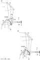
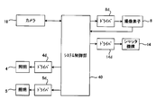
- the information reading apparatus 1 includes a transparent glass plate 3 that constitutes a placement unit on which the information recording medium 2 is placed, and an illumination 4 that irradiates light on the lower surface of the information recording medium 2 placed on the glass plate 3 ( 2 and 3), illumination 5 for irradiating light on the upper surface of the information recording medium 2 placed on the glass plate 3 (see FIGS. 2 and 3), and information recording placed on the glass plate 3
- An optical system 6 (see FIG. 4) for reading information recorded on the lower surface of the medium 2 and an optical system 7 (for reading information recorded on the upper surface of the information recording medium 2 placed on the glass plate 3). 4) and an image pickup device 8 (see FIGS.
- the upper surface portion 15a is formed in a rectangular flat plate shape, and is arranged so that the thickness direction of the upper surface portion 15a coincides with the vertical direction.
- the upper surface portion 15a is arranged so that the end surface of the upper surface portion 15a is parallel to the front-rear direction or the left-right direction.
- the side surface portion 15b is formed in a rectangular flat plate shape, and is arranged so that the thickness direction of the side surface portion 15b matches the left-right direction.
- the back surface portion 15c is formed in a rectangular flat plate shape, and is arranged so that the thickness direction of the back surface portion 15c matches the front-rear direction. Both ends of the back surface portion 15c in the left-right direction are connected to the back end of the side surface portion 15b.
- White light emitted from the white LED, infrared light emitted from the infrared LED, and ultraviolet light emitted from the ultraviolet LED are incident on the illumination lens 25, and light transmitted through the illumination lens 25 is irradiated onto the information recording medium 2.
- the infrared light emitted from the illuminations 4 and 5 is used for reading machine-readable printing information such as OCR characters.
- the ultraviolet light emitted from the illuminations 4 and 5 is used for reading print information necessary for authenticity determination of the information recording medium 2. Specifically, the ultraviolet light emitted from the illuminations 4 and 5 is used for reading print information with an invisible fluorescent coloring ink.
- the light reflected by the lower surface of the information recording medium 2 placed on the glass plate 3 enters the reflection mirror 30.
- the light reflected by the reflection mirror 30 enters the reflection mirror 31, and the light reflected by the reflection mirror 31 enters the reflection mirror 32.
- the optical axis of the light that is reflected by the lower surface of the information recording medium 2 and goes downward is bent backward. Further, in the reflection mirror 31, the optical axis of the light reflected by the reflection mirror 30 toward the rear side is bent upward, and in the reflection mirror 32, the optical axis of the light reflected by the reflection mirror 31 and directed upward is the rear side. Can be folded.
- the beam splitter 13 is formed in a rectangular flat plate shape.
- the beam splitter 13 is a half mirror having the same light transmittance and reflectance.
- the beam splitter 13 is disposed between the reflection mirror 32 and the imaging lens 35 in the front-rear direction. That is, the beam splitter 13 is disposed behind the reflecting mirror 32 and in front of the imaging lens 35. Further, the beam splitter 13 is disposed below the reflection mirror 34.
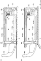
- a gap is formed between the pressing portion 41a and the protruding portion 43e in the vertical direction.
- a light passage portion 48 through which light emitted from the illumination 5 passes is provided. That is, on the upper surface of the information recording medium 2 on the glass plate 3, the light emitted from the illumination 5 and transmitted through the side surface portion 15 b is above the pressing portion 41 a and below the protruding portion 43 e. It becomes the light passage part 48 which passes toward.
- the push-up portion 41f is disposed on the front side with respect to the rotation center of the contact member 42 with respect to the holding member 43, and the contact portion 42a is disposed on the front side with respect to the push-up portion 41f.
- the lift amount of the contact portion 42a when lifted is larger than the lift amount of the push-up portion 41f lifted by the passport 2A. That is, when the passport 2A is inserted into the information reading apparatus 1, the amount of rise of the contact portion 42a is larger than the amount of rise of the presser portion 41a lifted by the passport 2A, and is larger than the thickness of the cover of the passport 2A. It has become.
- the amount of rise of the contact portion 42a is about three times the amount of rise of the presser portion 41a. Therefore, when the passport 2A is inserted into the information reading apparatus 1, the back end of the passport 2A (the back end of the cover 2s) passes below the contact portion 42a and enters the back side from the contact portion 42a.
- the holding portion 41a is lifted by the passport 2A to hold both the left and right ends of the passport 2A from the upper side, and the contact portion 42a is lifted.
- the back end of 2A passes below the contact portion 42a.
- the contact portion 42a is lifted in conjunction with the lifting operation of the presser portion 41a. Specifically, when the passport 2A is inserted into the information reading apparatus 1, the contact member 42 is pushed upward by the pressing member 41 and the contact portion 42a is lifted.
- the imaging range of the imaging device 8 of the information reading apparatus 1 is a range that combines the overlapping region 3 a and the non-overlapping region 3 b shown in FIG.
- the imaging range of the imaging device 8 of the information reading apparatus 1 is a range that combines the overlapping region 3 a and the non-overlapping region 3 b shown in FIG.
- the first sub-determination area 3A and the second sub-determination area 3B have the same position in the left-right direction and have the same shape.
- the first determination area 3A and the second sub determination area 3B constitute a first determination area.
- the second image data acquisition unit 40 ⁇ / b> B includes glass in the imaged image data output from the image sensor 8 by imaging the lower surface of the glass plate 3 with the image sensor 8 in a state where infrared light is irradiated from the illumination 4. Image data of the second determination areas 3R and 3L set on the plate 3 is acquired.
- the reference value K1 is obtained by imaging the lower surface of the glass plate 3 with the imaging element 8 in a state where the information recording medium 2 is not placed on the glass plate 3 and irradiating infrared light from the illumination 4. This is a value indicating the brightness of the image data in the first sub determination area 3A or the second sub determination area 3B in the output captured image data.
- the reference value K1 for example, an average value of pixel values of the image data is obtained in advance and stored in the ROM of the system control unit 40.
- the reference value K1 may be updated.
- the threshold value TH1 is determined based on a state in which an object containing many colors other than black overlaps the first sub determination area 3A or the second sub determination area 3B, and the first sub determination area 3A or the second sub determination area 3B. A value that can be distinguished from a state in which no object overlaps the sub determination region 3B is determined in advance.
- the information reading process is, for example, from the captured image data obtained by imaging the lower surface of the glass plate 3 to the back end portion of the end portion in the insertion direction of the information recording surface 2sa of the passport 2A. It is a series of processes for recognizing a certain character and outputting information of the recognized character to the host device as an information reading result.
- the system control unit 40 causes the imaging device 8 to capture an image of the lower surface of the glass plate 3 in a state where infrared light is irradiated from the illumination 4 (step S10).
- the upper surface of the glass plate 3 may be imaged by the imaging element 8 in a state where infrared light is irradiated from the illumination 5.
- step S12 the first image data acquisition unit 40A of the system control unit 40 uses the second sub determination region 3D set on the glass plate 3 in the captured image data.
- Image data is acquired (step S12).
- the image data of the second sub determination area 3D acquired by the first image data acquisition unit 40A is hereinafter referred to as image data 3GD.
- step S13 the medium placement detection unit 40C of the system control unit 40 obtains the brightness (average pixel value) of the image data 3GD, and whether the difference between the obtained brightness and the reference value K1 is equal to or greater than the threshold value TH1. It is determined whether or not (step S14). If the determination in step S14 is no, the process returns to step S10.
- step S16 when the process of step S16 is performed after the determination of step S12 is YES, the image data 3GC is acquired in step S16.
- step S16 is performed after the determination in step S14 is YES, image data 3GD is acquired in step S16.
- the information reading device includes an information reading apparatus including a first sub determination area and a second sub determination area set on the opening side of the first sub determination area.
- the first determination area includes the first sub determination area and the second sub determination area, the accuracy of detection by the medium placement detection unit can be increased.
- the first detection process and the second detection process are selectively performed according to the brightness of the image data in the second determination region.
- the brightness of the image data in the second determination area increases.
- the first detection process it is possible to determine whether or not the information recording medium has been inserted all the way.
- the second detection process it is possible to efficiently determine whether or not the information recording medium has been inserted to the proper position. In this way, the detection process can be changed depending on the size of the information recording medium, and the insertion of the information recording medium can be detected accurately and efficiently.
- the first information recording medium when the first information recording medium is inserted, the first information recording medium overlaps the second determination area, and when the second information recording medium is inserted, The second information recording medium does not overlap the second determination area.
- the second determination area in relation to the guide mechanism, it is possible to accurately determine the size of the information recording medium, which is either the first detection process or the second detection process. Can be accurately determined.
- a method for controlling an information reading apparatus which has a medium insertion portion in which an opening into which an information recording medium is inserted is formed and optically reads information from the information recording medium inserted in the medium insertion portion, the medium
- the insertion portion has a placement portion on which the information recording medium is placed, Of the imaged image data output from the image pickup device by picking up the image of the placement section with the image pickup device, the first set at the end opposite to the opening in the insertion direction of the information recording medium in the placement section.
- An information reading apparatus control method comprising: an information reading process step of reading information from the information recording medium based on data.
Landscapes
- Engineering & Computer Science (AREA)
- Physics & Mathematics (AREA)
- General Physics & Mathematics (AREA)
- Theoretical Computer Science (AREA)
- Multimedia (AREA)
- Computer Vision & Pattern Recognition (AREA)
- Artificial Intelligence (AREA)
- Signal Processing (AREA)
- Health & Medical Sciences (AREA)
- Electromagnetism (AREA)
- General Health & Medical Sciences (AREA)
- Toxicology (AREA)
- Facsimile Scanning Arrangements (AREA)
- Image Input (AREA)
Abstract
L'invention concerne un dispositif de lecture d'informations et son procédé de commande, au moyen desquels il est possible de déterminer avec précision qu'un support d'enregistrement d'informations a été défini dans un état de placement approprié pour la lecture et de réaliser efficacement la lecture d'informations. Un dispositif de lecture d'informations (1) : détecte le positionnement d'un support d'enregistrement d'informations (2) lorsqu'il est déterminé que, dans des données d'image capturées obtenues par imagerie d'une plaque de verre (3) à l'aide d'un élément d'imagerie (8), la luminosité des données d'image (3GC) (ou (3GD)) parmi des données d'image (3GC), (3GD) dans chaque image parmi une première région (3C) pour une sous-détermination et une seconde région (3D) pour une sous-détermination qui sont définies au niveau d'une partie d'extrémité (3Ey) sur le côté arrière dans la direction longitudinale de la plaque de verre (3) est supérieure à une valeur de référence d'une quantité supérieure ou égale à une valeur seuil ; et lance un processus de lecture d'informations contenues dans le support d'enregistrement d'informations (2) lorsqu'il est déterminé, sur la base d'une différence entre les données d'image (3GC) (ou (3GD) nouvellement acquises après cette détection et des données d'image (3GC) (ou (3GD) acquises immédiatement avant lesdites données d'image (3GC) (ou (3GD), que la position du support d'enregistrement d'informations (2) est maintenue.
Applications Claiming Priority (2)
| Application Number | Priority Date | Filing Date | Title |
|---|---|---|---|
| JP2018-083468 | 2018-04-24 | ||
| JP2018083468A JP2019193091A (ja) | 2018-04-24 | 2018-04-24 | 情報読取装置とその制御方法 |
Publications (1)
| Publication Number | Publication Date |
|---|---|
| WO2019208121A1 true WO2019208121A1 (fr) | 2019-10-31 |
Family
ID=68295277
Family Applications (1)
| Application Number | Title | Priority Date | Filing Date |
|---|---|---|---|
| PCT/JP2019/014617 Ceased WO2019208121A1 (fr) | 2018-04-24 | 2019-04-02 | Dispositif de lecture d'informations et son procédé de commande |
Country Status (2)
| Country | Link |
|---|---|
| JP (1) | JP2019193091A (fr) |
| WO (1) | WO2019208121A1 (fr) |
Cited By (1)
| Publication number | Priority date | Publication date | Assignee | Title |
|---|---|---|---|---|
| JP2022019175A (ja) * | 2020-07-17 | 2022-01-27 | 日本電産サンキョー株式会社 | モジュール |
Citations (4)
| Publication number | Priority date | Publication date | Assignee | Title |
|---|---|---|---|---|
| JPH0257964U (fr) * | 1988-10-24 | 1990-04-26 | ||
| JP2003078723A (ja) * | 2001-09-03 | 2003-03-14 | Omron Corp | 媒体処理装置および媒体処理システム |
| JP2015076681A (ja) * | 2013-10-07 | 2015-04-20 | キヤノン株式会社 | 情報処理装置とその制御方法、コンピュータプログラム、記憶媒体 |
| JP2018026804A (ja) * | 2016-08-08 | 2018-02-15 | 日本電産サンキョー株式会社 | 情報読取装置および情報読取装置の調整方法 |
-
2018
- 2018-04-24 JP JP2018083468A patent/JP2019193091A/ja active Pending
-
2019
- 2019-04-02 WO PCT/JP2019/014617 patent/WO2019208121A1/fr not_active Ceased
Patent Citations (4)
| Publication number | Priority date | Publication date | Assignee | Title |
|---|---|---|---|---|
| JPH0257964U (fr) * | 1988-10-24 | 1990-04-26 | ||
| JP2003078723A (ja) * | 2001-09-03 | 2003-03-14 | Omron Corp | 媒体処理装置および媒体処理システム |
| JP2015076681A (ja) * | 2013-10-07 | 2015-04-20 | キヤノン株式会社 | 情報処理装置とその制御方法、コンピュータプログラム、記憶媒体 |
| JP2018026804A (ja) * | 2016-08-08 | 2018-02-15 | 日本電産サンキョー株式会社 | 情報読取装置および情報読取装置の調整方法 |
Cited By (1)
| Publication number | Priority date | Publication date | Assignee | Title |
|---|---|---|---|---|
| JP2022019175A (ja) * | 2020-07-17 | 2022-01-27 | 日本電産サンキョー株式会社 | モジュール |
Also Published As
| Publication number | Publication date |
|---|---|
| JP2019193091A (ja) | 2019-10-31 |
Similar Documents
| Publication | Publication Date | Title |
|---|---|---|
| CN102077567B (zh) | 读取装置 | |
| JP2019212194A (ja) | 情報読取装置とその制御方法 | |
| CN109565531A (zh) | 信息读取装置 | |
| JP2008523502A (ja) | スワイプイメージャースキャンエンジン | |
| CN101647029A (zh) | 取得指纹的装置和方法 | |
| JP2001043301A (ja) | 二次元コード読取装置 | |
| JP2020170366A (ja) | 手持ち式光学情報読取装置 | |
| US8559073B2 (en) | Booklet reading device | |
| JP4473933B1 (ja) | 読取装置 | |
| WO2019208121A1 (fr) | Dispositif de lecture d'informations et son procédé de commande | |
| JP2019080221A (ja) | 情報読取装置 | |
| TWI512635B (zh) | 身分證偽造變造真偽識別裝置 | |
| JP4471401B1 (ja) | 帳票読取り装置および帳票検出方法 | |
| US20200145551A1 (en) | Information reading device | |
| JP2019193090A (ja) | 情報読取装置とその制御方法 | |
| JP7212532B2 (ja) | 情報読取装置の使用方法 | |
| KR101460686B1 (ko) | 홀로그램 처리기능을 가지는 스캔 장치 및 스캔 방법 | |
| WO2018198752A1 (fr) | Dispositif de lecture d'informations | |
| JP2010200186A (ja) | 読取装置 | |
| JP4157759B2 (ja) | コード読み取り装置 | |
| JP6950176B2 (ja) | 撮像画像保存装置および情報管理システム | |
| JP4729363B2 (ja) | 写真辺検出装置、idカード作成装置、写真辺検出方法及びidカード作成方法 | |
| US20140125786A1 (en) | Topping foil vision verification system | |
| WO2018030377A1 (fr) | Dispositif de lecture d'informations | |
| JPH0684007A (ja) | 光学的文字読取装置 |
Legal Events
| Date | Code | Title | Description |
|---|---|---|---|
| 121 | Ep: the epo has been informed by wipo that ep was designated in this application |
Ref document number: 19791979 Country of ref document: EP Kind code of ref document: A1 |
|
| NENP | Non-entry into the national phase |
Ref country code: DE |
|
| 122 | Ep: pct application non-entry in european phase |
Ref document number: 19791979 Country of ref document: EP Kind code of ref document: A1 |