WO2019208413A1 - 光伝送装置、光受信装置、光通信システム、光伝送方法、設定方法及びコンピュータ可読媒体 - Google Patents
光伝送装置、光受信装置、光通信システム、光伝送方法、設定方法及びコンピュータ可読媒体 Download PDFInfo
- Publication number
- WO2019208413A1 WO2019208413A1 PCT/JP2019/016753 JP2019016753W WO2019208413A1 WO 2019208413 A1 WO2019208413 A1 WO 2019208413A1 JP 2019016753 W JP2019016753 W JP 2019016753W WO 2019208413 A1 WO2019208413 A1 WO 2019208413A1
- Authority
- WO
- WIPO (PCT)
- Prior art keywords
- transmission
- band
- optical
- signal
- stage
- Prior art date
- Legal status (The legal status is an assumption and is not a legal conclusion. Google has not performed a legal analysis and makes no representation as to the accuracy of the status listed.)
- Ceased
Links
Images






Classifications
-
- H—ELECTRICITY
- H04—ELECTRIC COMMUNICATION TECHNIQUE
- H04J—MULTIPLEX COMMUNICATION
- H04J14/00—Optical multiplex systems
- H04J14/02—Wavelength-division multiplex systems
- H04J14/0201—Add-and-drop multiplexing
- H04J14/0202—Arrangements therefor
- H04J14/0209—Multi-stage arrangements, e.g. by cascading multiplexers or demultiplexers
-
- H—ELECTRICITY
- H04—ELECTRIC COMMUNICATION TECHNIQUE
- H04B—TRANSMISSION
- H04B10/00—Transmission systems employing electromagnetic waves other than radio-waves, e.g. infrared, visible or ultraviolet light, or employing corpuscular radiation, e.g. quantum communication
- H04B10/60—Receivers
- H04B10/66—Non-coherent receivers, e.g. using direct detection
- H04B10/67—Optical arrangements in the receiver
-
- H—ELECTRICITY
- H04—ELECTRIC COMMUNICATION TECHNIQUE
- H04B—TRANSMISSION
- H04B10/00—Transmission systems employing electromagnetic waves other than radio-waves, e.g. infrared, visible or ultraviolet light, or employing corpuscular radiation, e.g. quantum communication
- H04B10/50—Transmitters
- H04B10/501—Structural aspects
- H04B10/506—Multiwavelength transmitters
-
- H—ELECTRICITY
- H04—ELECTRIC COMMUNICATION TECHNIQUE
- H04B—TRANSMISSION
- H04B10/00—Transmission systems employing electromagnetic waves other than radio-waves, e.g. infrared, visible or ultraviolet light, or employing corpuscular radiation, e.g. quantum communication
- H04B10/50—Transmitters
- H04B10/572—Wavelength control
-
- H—ELECTRICITY
- H04—ELECTRIC COMMUNICATION TECHNIQUE
- H04J—MULTIPLEX COMMUNICATION
- H04J14/00—Optical multiplex systems
- H04J14/02—Wavelength-division multiplex systems
- H04J14/0227—Operation, administration, maintenance or provisioning [OAMP] of WDM networks, e.g. media access, routing or wavelength allocation
- H04J14/0254—Optical medium access
- H04J14/0256—Optical medium access at the optical channel layer
Definitions
- the present invention relates to an optical communication system that transmits and receives an optical signal via a transmission line.
- the optical transmission device provided in the terminal station is provided with a multiplexing / demultiplexing device for transmitting a wavelength division multiplexed optical signal including a plurality of optical signals.
- WSS Widelength Selective Switch
- the optical transmission device provided in the terminal station is provided with a multiplexing / demultiplexing device for transmitting a wavelength division multiplexed optical signal including a plurality of optical signals.
- WSS Widelength Selective Switch
- WSS has a plurality of ports through which optical signals are input, and a wavelength band for filtering the input optical signals is set for each port.
- the WSS filters each input optical signal to make an optical signal in a predetermined frequency band, and then multiplexes, and outputs the multiplexed optical signal after multiplexing to the transmission line.
- the WSS filters each optical signal in a wavelength band substantially equal to the wavelength band of each input optical signal.
- the optical spectrum is narrowed due to the filter characteristics of WSS.
- the edges of the WSS filter at the first stage and the WSS filter at the next stage may be overlapped or close to each other. In that case, the signal band of the optical signal transmitted through these filters may be excessively narrowed. This may affect the transmission quality.
- An object of the present invention is to provide an optical transmission device that can suppress narrowing of the bandwidth of an optical signal that occurs when a plurality of multiplexing / demultiplexing devices are provided.
- the optical transmission device of the present invention includes a first multiplexing device that outputs a first wavelength multiplexed signal obtained by multiplexing each of the first post-processing signals obtained by performing the first filter processing on each of the input transmission optical signals.
- a second multiplexing device that outputs a second wavelength multiplexed signal obtained by multiplexing each of the first wavelength multiplexed signals that have been subjected to the second filter processing, and in a transmission band according to each of the first filter processing
- Each of the upper limit and the lower limit of each of the certain first transmission bands is different from each of the upper limit and the lower limit of each of the second transmission bands that are transmission bands according to each of the second filter processes.
- the transfer control device or the like according to the present invention can suppress the narrowing of the optical signal band that occurs when a plurality of multiplexing / demultiplexing devices are provided.
- FIG. 1 is a conceptual diagram illustrating a configuration of an optical transmission device 100a that is an example of the optical transmission device according to the first embodiment.
- the optical transmission device 100a includes multiplexing devices 101a to 10na, which are n multiplexing devices, and a multiplexing device 106a.
- n is a number of 2 or more.
- Each of the transmission optical signals s11 to s1m is input from the transmitters 611 to 61m, which are m transmitters, to the multiplexer 101a.
- the transmission optical signals s11 to s1m are optical signals having different wavelengths.
- the transmission optical signals s11 to s1m are optical signals of different channels.
- the channel refers to a wavelength grid defined by a predetermined center frequency interval and frequency bandwidth.
- the multiplexer 101a is a first-stage multiplexer as viewed from the transmitters 611 to 61m.
- the multiplexer 101a performs transmission filter processing (first-stage transmission filter processing (first filter processing)) that transmits each set transmission band (frequency band) set for each of the transmission optical signals s11 to s1m.
- the set transmission bands do not overlap each other.
- the multiplexing device 101a may be configured by WSS.
- the multiplexing apparatus 101a may include a plurality of ports through which the transmission optical signals s11 to s1m are input, and a transmission band may be set for each port.
- the multiplexing apparatus 101a multiplexes the transmission optical signals after the first-stage transmission filter processing, and inputs the first-stage multiplexed transmission optical signal that is the transmission optical signal after the multiplexing to the multiplexing apparatus 106a.
- the multiplexer 106a is a next-stage multiplexer as viewed from the transmitters 611 to 61m. Next, the multiplexer 106a transmits the set transmission band set for each of the first-stage multiplexed transmission optical signals for each of the first-stage multiplexed transmission optical signals after the multiplexing input from each of the multiplexing apparatuses 101a to 10na. Step transmission filter processing (second filter processing) is performed. The set transmission bands related to the next-stage transmission filter process do not overlap each other.
- the multiplexing device 106a may be composed of WSS.
- the multiplexer 106a includes a plurality of ports that are input from the multiplexers 101a to 10na and that receive the first-stage multiplexed transmission optical signals after multiplexing, and a transmission band is set for each port. You may make it do.
- transmission related to the filter processing means that the attenuation amount of the signal subjected to the filter processing is equal to or less than a predetermined value.
- the attenuation amount is, for example, 3 dB.
- a band where the attenuation amount of the signal subjected to the filter processing is a predetermined value or less may be referred to as a transmission region, and a band where the attenuation amount is a predetermined value or more may be referred to as a cutoff region.
- the multiplexer 106a combines the first-stage multiplexed transmission optical signals after the next-stage transmission filter processing, and outputs the combined next-stage multiplexed transmission optical signals to the transmission line 300a.
- the next-stage multiplex transmission optical signal is transmitted to a reception-side optical transmission apparatus (not shown).
- the upper and lower limits of each set transmission band related to the first-stage transmission filter process do not overlap with the upper and lower limits of the set transmission band related to the next-stage transmission filter process.
- the upper and lower limits of the set transmission band may be referred to as edges.
- each of two frequencies “overlapping”, “matching”, and “equal” means that the two frequencies are the same or close to each other.
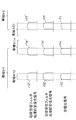
- FIG. 2 is a conceptual diagram illustrating an example of a set transmission band related to transmission filter processing performed in the multiplexing apparatuses 101a and 106a for the transmission optical signals s11 to s1m illustrated in FIG.
- FIG. 2A shows a set transmission band related to transmission filter processing in each of the multiplexing apparatuses 101a, 10na, and 106a shown in FIG.
- FIG. 2B shows a transmission optical signal after the next-stage transmission filter processing in the case where each transmission band is the one shown in FIG.
- FIG. 2C shows a transmission optical signal after the next-stage transmission filter processing in the case of a general set transmission band.
- the multiplexer can set a band related to the filter processing in units of a predetermined band.
- a band related to filter processing is set so as to include a transmission optical signal channel that is transmitted and not include a transmission optical signal channel that is not transmitted.
- the upper limit of the band 40 m that is the set transmission band related to the first-stage transmission filter process and the upper limit of the band 501 that is the set transmission band related to the next-stage transmission filter process are the same.
- FIGS. 2B and 2C show the optical spectra of the transmission optical signals s11 to s1m.
- the transmission optical signals s11 to s1m are optical signals of channels in the illustrated bands.
- Bands 401 to 40m shown in FIG. 2A are set transmission bands set for the transmission optical signals s11 to s1m in this order in the multiplexing apparatus 101a.
- the bands 401 to 40m have bands including the wavelengths of the transmission optical signals s11 to s1m, respectively.
- Bands 401 to 40m are higher frequency bands in this order.
- the bands 401 to 40m do not overlap each other.
- the band 501 is a set transmission band related to the next-stage transmission filter processing performed on the first-stage multiplexed transmission optical signal input from the multiplexing apparatus 101a in the multiplexing apparatus 106a.
- the band 501 has a band that includes the wavelengths of the transmission optical signals s11 to s1m constituting the first-stage multiplexed transmission optical signal.
- the frequency f4mb that is the upper limit of the band 40m set by the multiplexing device 101a is located on the higher frequency side than the frequency f51b set by the multiplexing device 106a.
- the band 40m is a set transmission band set by the multiplexing apparatus 101a for the transmission optical signal s1m.
- the transmission optical signals s11 to s1m constitute the first-stage multiplexed transmission optical signal output from the multiplexer 101a, and the transmission optical signal s1m is the optical signal of the channel on the highest frequency side among the first-stage multiplexing transmission optical signals.
- the channel of the transmission optical signal s1m may be referred to as an edge channel included in the first-stage multiplexed transmission optical signal.
- the edge of the band 40 m where the multiplexer 101 a filters the optical signal of the edge channel is located on the higher frequency side than the band 501. That is, the band 40m is provided to include a band outside the band 501.
- FIG. 3 is a diagram showing a setting example of the band 40 m.
- the transmission optical signal s1 (m + 1) indicating the spectrum with a dotted line is an optical signal that is not included in the first-stage multiplexed optical signal composed of the transmission optical signals s11 to s1m.
- the channel of the transmission optical signal s1 (m + 1) is adjacent to the channel of the transmission optical signal s1m.
- the band 40m may be set to include at least a part of the channel of the transmission optical signal s1 (m + 1), that is, the adjacent channel of the transmission optical signal s1m.
- FIG. 4 is a diagram showing another setting example of the band 40 m.
- the center frequency of the channel of the transmission optical signal s1m or the center frequency of the band related to the filter processing generally set to transmit the transmission optical signal s1m is denoted by fc.
- the band related to the filter processing that is generally set as described above is a band that includes a transmission optical signal channel that is transmitted and does not include a transmission optical signal channel that is not transmitted.
- a frequency that is 3 dB lower than the transmission power of the center frequency fc is a low frequency
- high frequencies are frequencies f1 and f2, respectively.
- the upper limit frequency f4mb may be set so as to include N / 2 [GHz] or more on the high frequency side.
- the band 40m may be provided so as to include a band outside the band 501, and the bandwidth of the band 40a is not limited to the band illustrated in FIG. 3 or FIG.
- the signal level in the vicinity of the upper limit of the signal band in the transmission optical signal s1m ′′ is greatly reduced. This is because both the influence of the processing and the influence of the next-stage transmission filter processing are received.Therefore, the signal band of the transmission optical signal s1m ′′ is narrowed.
- the transmission optical signal s1m ′′ in the transmission optical signal s1m ′′, the transmission optical signal as shown in FIG. There is no narrowing of the signal band of s1m ′′.
- the upper limit of the signal band of the transmission optical signal s1m ′′ is determined by the frequency f51b which is the upper limit of the band 501 related to the next-stage transmission filter processing, and the influence of the frequency f4mb which is the upper limit of the band 40m related to the first-stage transmission filter processing. It is because it does not receive.
- the transmission optical signal s1m of the edge channel has been described as the optical signal on the highest frequency side among the first-stage multiplexed transmission optical signals, but the same configuration is provided even on the optical signal on the lowest frequency side. Applicable.
- the optical transmission device 100a may be configured as an OCI (Open Cable Interface).
- the transmitters 611 to 61m connected to the optical transmission device 100a may be manufactured by a plurality of different vendors.
- optical transmission device of the present embodiment may include three or more stages of multiplexing devices.
- the optical transmission apparatus of the present embodiment may perform three or more stages of transmission filter processing.
- the set transmission band related to the transmission filter process is set so that the lower limit and the upper limit of the set transmission band related to the transmission filter process at each stage do not overlap each other.
- neither the lower limit nor the upper limit of each set transmission band related to the first-stage transmission filter process overlaps with either the lower limit or the upper limit of the set transmission band related to the next-stage transmission filter process.
- the lower limit and the upper limit of the transmission band related to the first-stage transmission filter process and the transmission band related to the next-stage transmission filter process do not overlap for the edge channel optical signal among the first-stage multiplexed transmission optical signals.
- the second embodiment is an embodiment relating to an optical communication system including optical transmission apparatuses on a transmission side and a reception side.
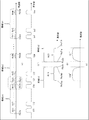
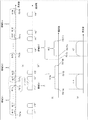
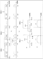
- FIG. 5 is a conceptual diagram showing a configuration of an optical communication system 800 that is an example of the optical communication system according to the second embodiment.
- the optical communication system 800 includes a transmission side optical transmission device 100, a reception side optical transmission device 200, and a transmission path 300.
- Each of the transmission-side optical transmission device 100 and the reception-side optical transmission device 200 may be configured as an OCI (Open Cable Interface).
- OCI Open Cable Interface
- the transmission side optical transmission apparatus 100 includes WSS_CH_MUXs 101 to 10n which are n optical multiplexing apparatuses and a WSS_Band_MUX 106 which is an optical multiplexing apparatus.
- Each of the transmission optical signals t11 to t1m is input to the WSS_CH_MUX 101 from each of the m transmitters T11 to T1m.
- WSS_CH_MUX 101 is a first-stage multiplexing device as seen from the transmitters T11 to T1m.
- the WSS_CH_MUX 101 performs the above-described first-stage transmission filter processing for transmitting each set transmission band set for each transmission optical signal for each of the transmission optical signals t11 to t1m.
- the set transmission bands are set so as not to overlap each other.
- the multiplexing apparatus 101a multiplexes the transmission optical signals after the first-stage transmission filter processing, and inputs the first-stage multiplexed transmission optical signal, which is the transmission optical signal after the multiplexing, to the WSS_Band_MUX 106.
- WSS_Band_MUX 106 is a next-stage multiplexer as viewed from transmitters T11 to Tnm.
- the WSS_Band_MUX 106 performs, for each of the first-stage multiplexed transmission optical signals input from each of the WSS_CH_MUXs 101 to 10n, a next-stage transmission filter process that transmits the set transmission band set for each of the first-stage multiplexed transmission optical signals.
- the set transmission bands related to the next-stage transmission filter processing are set so as not to overlap each other.
- the WSS_Band_MUX 106 multiplexes the first-stage multiplexed transmission optical signals after the next-stage transmission filter processing, and inputs the combined next-stage multiplexed transmission optical signals to the transmission path 300.
- the next-stage multiplex transmission optical signal is sent toward the reception-side optical transmission apparatus 200.
- each of the upper limit and lower limit of each set transmission band related to the first-stage transmission filter process overlaps with each of the upper limit and lower limit of the set transmission band related to the next-stage transmission filter process. It is set not to be.
- the reception-side optical transmission device 200 includes a WSS_Band_DEMUX 206 that is an optical demultiplexing device and WSS_CH_DEMUXs 201 to 20n that are n optical demultiplexing devices.
- WSS_Band_DEMUX 206 receives a first-stage multiplexed received optical signal from transmission-side optical transmission apparatus 100 through transmission path 300.
- the first-stage multiplex reception optical signal is the above-described next-stage multiplex transmission optical signal after being transmitted from the transmission-side optical transmission apparatus 100 and passing through the transmission path 300.
- WSS_Band_DEMUX 206 is a first-stage demultiplexing device when viewed from the transmission path 300.
- the WSS_Band_DEMUX 206 demultiplexes the input first-stage multiplexed received optical signal into a first-stage demultiplexed received optical signal that is an optical signal of n signal bands.
- the WSS_Band_DEMUX 206 performs filter processing (first-stage reception filter processing) for transmitting each set transmission band set for the received optical signal after the first-stage demultiplexing for each received optical signal after the first-stage demultiplexing.
- the set transmission bands are set so as not to overlap each other.
- each of the next-stage received multiplexed optical signals that are the received optical signals after the first-stage demultiplexing subjected to the first-stage receive filter processing are input to corresponding ones of WSS_CH_DEMUX 201 to 20n according to the set transmission band. .
- WSS_CH_DEMUX 201 demultiplexes the next-stage multiplexed received optical signal input from WSS_Band_DEMUX 206 into received optical signals of m signal bands.
- Each received optical signal that has been demultiplexed becomes each of the received optical signals r11 to r1m by the next-stage reception filter processing of the set transmission band set for each received optical signal.
- Each of the reception optical signals r11 to r1m is an optical signal corresponding to each of the transmission optical signals t11 to t1m in this order.
- the received optical signals r11 to r1m are input to the receivers R11 to R1m in this order.
- each edge of each set transmission band related to the first-stage reception filter process is set so as not to overlap each edge of each set transmission band related to the next-stage transmission filter process. ing.
- FIG. 6 is a diagram showing a general set transmission band related to the first-stage transmission filter processing and the next-stage transmission filter processing.
- FIG. 6A ' shows the transmission optical signals t11 to tnm shown in FIG.
- FIG. 6B is an enlarged view of a portion surrounded by a broken line shown in FIG.
- FIG. 6C is an image diagram showing a transmission optical signal after receiving the first-stage transmission filter processing and the next-stage transmission filter processing of the set transmission band shown in FIG. 6B.
- each of the bands 4s11 to 4s1m represents the set transmission band related to the above-described first-stage transmission filter processing performed for each of the transmission optical signals t11 to t1m in the WSS_CH_MUX 101.
- each of the bands 5s1 to 5sn represents a set transmission band related to the next-stage transmission filter process.
- the next-stage transmission filter processing is performed on the first-stage multiplexed transmission optical signal obtained by combining the transmission optical signals t11 to t1m subjected to the first-stage transmission filter processing in the WSS_Band_MUX 106 illustrated in FIG.
- the channels of the transmission optical signals are adjacent to each other, and the channels of the transmission optical signals t11 to t1m, t21 to t2m, and t31 to t3m shown in FIG.
- the transmission optical signals t1m and t21 are optical signals constituting different first-stage multiplexed optical signals, but are optical signals of adjacent channels.
- the frequency f4s1mb that is the upper limit of the band 4s1m substantially matches the frequency f5s1b that is the upper limit of the band 5s1. Further, the frequency f4s21a that is the lower limit of the band 4s21 substantially matches the frequency f5s2a that is the lower limit of the band 5s2.
- the frequency f5s2b which is the upper limit of the band 5s2, and the upper limit of the band 4s2m substantially coincide with each other.
- the frequency f5sna which is the lower limit of the band 5sn, substantially matches the lower limit of the band 4sn1.
- the frequency f5s1a which is the lower limit of the band 5s1
- the frequency f5snb which is the upper limit of the band 5sn, is set on the higher frequency side than the band 4snm.
- the transmission optical signal t1m ′′ shown in FIG. 6C is shown in FIG. 5 in which the first-stage transmission filter processing in which the set transmission band is the band 4s1m and the next-stage transmission filter processing in which the setting transmission band is the band 5s1 are performed. This is the transmission optical signal t1m.
- the signal intensity in the vicinity of the upper limit of the signal band of the transmission optical signal t1m ′′ is significantly reduced because it is affected by both the first-stage transmission filter processing and the next-stage transmission filter processing. Therefore, the signal of the transmission optical signal t1m ′′ The band is significantly narrowed.
- the transmission optical signal t21 ′′ is a transmission optical signal t21 shown in FIG. 5 in which the first-stage transmission filter processing in which the set transmission band is the band 4s21 and the next-stage transmission filter processing in which the setting transmission band is the band 5s2. is there.
- the signal intensity in the vicinity of the lower limit of the signal band of the transmission optical signal t21 ′′ is significantly reduced because it is affected by both the first-stage transmission filter processing and the next-stage transmission filter processing. Therefore, the signal of the transmission optical signal t21 ′′ The band is significantly narrowed.
- FIG. 7 is an image diagram showing a transmission optical signal after transmission filter processing at each stage when the setting transmission band shown in FIG. 6 is set in the transmission-side optical transmission apparatus 100 shown in FIG.
- the horizontal axis of each signal shown in FIG. 7 is frequency, and the vertical axis is signal intensity.
- the transmission optical signal t12 shown in FIG. 5 becomes a transmission optical signal t12 'having a signal band equal to the band 4s12 by the first-stage transmission filter processing in which the set transmission band is the band 4s12.
- the band 5s1 which is the set transmission band related to the next-stage transmission filter process, includes the signal band of the transmission optical signal t12 '. Therefore, the signal band of the transmission optical signal t12 ′′ after the next-stage transmission filter processing is the same as that of the transmission optical signal t12 ′.
- the upper limit of the signal band of the transmission optical signal t1m is on the higher frequency side than the upper limit of the band 5s1. Therefore, the upper limit of the signal band of the transmission optical signal t1m ′ after the first-stage reception filter processing is the upper limit of the band 5s1.
- the lower limit of the signal band of the transmission optical signal t1m is in the band 5s1. Therefore, the shape in the vicinity of the lower limit of the signal band of the transmission optical signal t1m is equal to the shape in the vicinity of the lower limit of the signal band of the transmission optical signal t1m after the first-stage reception filter processing.
- the signal band upper limit of the transmission optical signal t1m ′ becomes equal to the upper limit of the band 5s1 by the first-stage transmission filter processing in which the set transmission band is the band 5s1.
- the upper limit of the band 5s1 which is the set transmission band related to the next-stage transmission filter process, matches the upper limit of the band 4s1m. Therefore, the signal level on the high frequency side of the signal band of the transmission optical signal t1m ′′ after the next-stage transmission filter processing is further reduced by the next-stage transmission filter processing. Therefore, the transmission optical signal t1m ′′ is the transmission optical signal. Compared with t12 ′′, the signal band is significantly narrowed.
- the transmission optical signal t21 becomes a transmission optical signal t21 'having a signal band equal to the band 4s21 by the first-stage transmission filter processing in which the set transmission band is the band 4s21.
- the signal band of the transmission optical signal after the next-stage transmission filter processing can be significantly narrowed. .
- FIG. 8 is a diagram illustrating an example of the second embodiment of the set transmission band related to the first-stage transmission filter process and the next-stage transmission filter process.
- FIG. 8A ' shows the transmission optical signals t11 to tnm shown in FIG.
- FIG. 8B is an enlarged view of a portion surrounded by a broken line shown in FIG.
- FIG. 8C is an image diagram showing a transmission optical signal after receiving the first-stage transmission filter processing and the next-stage transmission filter processing of the set transmission band shown in FIG. 8B.
- the frequency f4s1mb that is the upper limit of the band 4s1m is set higher than the frequency f5s1b that is the upper limit of the band 5s1. Further, the frequency f4s21a that is the lower limit of the band 4s21 is set to the lower frequency side than the frequency f5s2a that is the lower limit of the band 5s2.
- the upper limit of the band 4s2m is set on the higher frequency side than the frequency f5s2b which is the upper limit of the band 5s2.
- the lower limit of the band 4sn1 is set on the lower frequency side than the frequency f5sna which is the lower limit of the band 5sn.
- the frequency f5s1a which is the lower limit of the band 5s1
- the frequency f5snb which is the upper limit of the band 5sn, is set on the higher frequency side than the band 4snm.
- the optical signal t1m ′′ shown in FIG. 8C is the light shown in FIG. 5 that has been subjected to the first-stage transmission filter processing in which the set transmission band is the band 4s1m and the next-stage transmission filter processing in which the setting transmission band is the band 5s1.
- Signal t1m is the light shown in FIG. 5 that has been subjected to the first-stage transmission filter processing in which the set transmission band is the band 4s1m and the next-stage transmission filter processing in which the setting transmission band is the band 5s1.
- the signal intensity in the vicinity of the upper limit of the signal band of the optical signal t1m ′′ is affected by the next-stage transmission filter process, but not affected by the first-stage transmission filter process. Also, in the vicinity of the lower limit of the signal band of the optical signal t1m ′′. Is affected by the first-stage transmission filter process, but is not affected by the next-stage transmission filter process. For this reason, the signal strengths near the upper limit and the lower limit of the signal band of the optical signal t1m ′′ are not significantly reduced by being affected by both the first-stage transmission filter processing and the next-stage transmission filter processing. Therefore, the optical signal t1m The signal band "" is not narrowed like the signal band of the optical signal t1m "shown in FIG.
- the transmission optical signal t21 ′′ is a transmission optical signal t21 shown in FIG. 5 in which the first-stage transmission filter processing in which the set transmission band is the band 4s21 and the next-stage transmission filter processing in which the setting transmission band is the band 5s2. is there.
- the signal intensity in the vicinity of the upper limit of the signal band of the transmission optical signal t21 ′′ is affected by the first-stage transmission filter process, but not affected by the next-stage transmission filter process.
- the signal band of the transmission optical signal t21 ′′ The signal strength in the vicinity of the lower limit is affected by the next-stage transmission filter process, but not affected by the first-stage transmission filter process. For this reason, the signal strengths near the upper limit and the lower limit of the signal band of the transmission optical signal t21 ′′ are not significantly reduced due to both the influence of the first-stage transmission filter processing and the influence of the next-stage transmission filter processing.
- the signal band of the signal t21 ′′ is not narrowed like the signal band of the transmission optical signal t21 ′′ shown in FIG.
- FIG. 9 is an image diagram showing the transmission optical signal after the transmission filter processing at each stage when the setting transmission band shown in FIG. 8 is set in the transmission-side optical transmission apparatus 100 shown in FIG.
- the horizontal axis of each signal shown in FIG. 9 is frequency, and the vertical axis is signal intensity.
- the transmission optical signal t12 shown in FIG. 9 becomes a transmission optical signal t12 'having a signal band equal to the band 4s12 by the first-stage transmission filter processing in which the set transmission band is the band 4s12.
- the band 5s1 which is the set transmission band related to the next-stage transmission filter process, includes the signal band of the transmission optical signal t12 '. Therefore, the signal band of the transmission optical signal t12 ′′ after the next-stage transmission filter processing is the same as that of the transmission optical signal t12 ′.
- the lower limit of the signal band of the transmission optical signal t1m coincides with the lower limit of the band 4s1m by the first-stage transmission filter processing in which the set transmission band is the band 4s1m.
- the upper limit of the band 4s1m is set higher than the upper limit of the signal band of the transmission optical signal t1m. Therefore, the shape near the signal band upper limit of the transmission optical signal t1m is not affected by the first-stage transmission filter processing. Therefore, the shape of the vicinity of the upper limit of the signal band of the transmission optical signal t1m is equal to the shape of the vicinity of the upper limit of the signal band of the transmission optical signal t1m ′ after the first-stage transmission filter processing.
- the shape of the transmission optical signal t1m ′′ after the next-stage transmission filter processing is equal to the shape near the signal band lower limit of the transmission optical signal t1m ′.
- the vicinity of the upper limit of the signal band of the transmission optical signal t1m ′ is higher than the upper limit of the band 5s1. Therefore, the upper limit of the transmission optical signal t1m ′′ becomes equal to the upper limit of the band 5s1 by the next-stage transmission filter processing.
- the signal band of the transmission optical signal t1m ′′ after the next-stage transmission filter processing is set by the lower limit of the band 4s1m and the upper limit of the band 5s1. Further, the shape in the vicinity of the upper limit of the signal band of the transmission optical signal t1m ′. Is affected by the first-stage transmission filter processing, but is not affected by the first-stage transmission filter processing. Therefore, the shape of the transmission optical signal t1m ′′ in the vicinity of the signal band upper limit is affected by the first-stage transmission filter processing. As a result of the double influence of the next-stage transmission filter processing, there is no significant decrease in signal strength as occurs in the transmission optical signal t1m ′′ shown in FIG.
- the upper limit of the signal band of the transmission optical signal t21 is on the higher frequency side than the upper limit of the band 4s21. Therefore, the upper limit of the signal band of the transmission optical signal t21 coincides with the upper limit of the band 4s21 by the first-stage transmission filter processing in which the set transmission band is the band 4s21.
- the lower limit of the band 4s21 is set on the lower frequency side than the lower limit of the signal band of the transmission optical signal t21. Therefore, the shape near the signal band lower limit of the transmission optical signal t21 is not affected by the first-stage transmission filter processing. Therefore, the shape near the signal band lower limit of the transmission optical signal t21 'matches the shape near the signal band lower limit of the transmission optical signal t21 after the first-stage transmission filter processing.
- the lower limit of the signal band of the transmission optical signal t21 ' is set on the lower frequency side than the lower limit of the band 5s1. Therefore, the shape in the vicinity of the lower limit of the signal band of the transmission optical signal t21 ′′ after the next-stage transmission filter processing is equal to the shape in the vicinity of the lower limit of the band 5s1.
- the shape of the transmission optical signal t21 'near the signal band upper limit is set within the band 5s1. Therefore, the shape in the vicinity of the signal band upper limit of the transmission optical signal t21 ′′ after the next-stage transmission filter processing is equal to the shape in the vicinity of the signal band upper limit of the transmission optical signal t21 ′.
- the signal band of the transmission optical signal t21 ′′ after the next-stage transmission filter processing is set by the upper limit of the band 4s21 and the lower limit of the band 5s1. Further, the signal near the signal band lower limit of the transmission optical signal t21 ′′.
- the strength is affected by the next-stage transmission filter process, but is not affected by the first-stage transmission filter process. Therefore, the shape of the transmission optical signal t21 ′′ in the vicinity of the upper limit of the signal band is generated in the transmission optical signal t21 ′′ shown in FIG. 7 that is caused by double influences of the first-stage transmission filter processing and the next-stage transmission filter processing. The signal strength is not significantly reduced.
- FIG. 10 is a diagram illustrating a second setting example of the second embodiment of the set transmission band related to the first-stage transmission filter process and the next-stage transmission filter process.
- FIG. 10A ' shows the transmission optical signals t11 to tnm shown in FIG.
- FIG. 10B is an enlarged view of a portion surrounded by a broken line shown in FIG.
- FIG. 10C is an image diagram showing a transmission optical signal after receiving the first-stage transmission filter processing and the next-stage transmission filter processing of the set transmission band shown in FIG. 10B.
- the transmission optical signal t1m and the transmission optical signal t21 are not of channels adjacent to each other, and there is a bandwidth that does not belong to any channel between the two transmission optical signals. To do.
- the bandwidth for example, there is an empty channel that is not used for transmission of a transmission optical signal as shown in FIG.
- the empty channel is illustrated as the channel of the transmission optical signal t1 (m + 1) in FIG.
- the transmission optical signal t1 (m + 1) is a transmission optical signal that is not actually used, and is an optical signal that is not input to the WSS_Band_MUX 106.
- the bandwidth of the empty channel is not limited to the case where the bandwidth is equal to that of other received optical signals as shown in the figure.
- the frequency f4s1mb that is the upper limit of the band 4s1m is set to be higher than the frequency f5s1b that is the upper limit of the band 5s1.
- the frequency f4s21a, which is the lower limit of the band 4s21, is set on the higher frequency side than the frequency f5s2a, which is the lower limit of the band 5s2.
- the upper limit of the band 4s2m is set on the higher frequency side than the frequency f5s2b which is the upper limit of the band 5s2.
- the lower limit of the band 4sn1 is set on the higher frequency side than the frequency f5sna which is the lower limit of the band 5sn.
- the frequency f5s1a which is the lower limit of the band 5s1
- the frequency f5snb which is the upper limit of the band 5sn, is set on the higher frequency side than the upper limit of the band 4snm.
- the optical signal t1m ′′ shown in FIG. 10C is the light shown in FIG. 5 that has undergone the first-stage transmission filter processing in which the set transmission band is the band 4s1m and the next-stage transmission filter processing in which the setting transmission band is the band 5s1.
- Signal t1m is the light shown in FIG. 5 that has undergone the first-stage transmission filter processing in which the set transmission band is the band 4s1m and the next-stage transmission filter processing in which the setting transmission band is the band 5s1.
- the signal intensity in the vicinity of the upper limit of the signal band of the optical signal t1m ′′ is affected by the next-stage transmission filter process, but not affected by the first-stage transmission filter process. Also, in the vicinity of the lower limit of the signal band of the optical signal t1m ′′. Is affected by the first-stage transmission filter process, but is not affected by the next-stage transmission filter process. For this reason, the signal strengths near the upper limit and the lower limit of the signal band of the optical signal t1m ′′ are not significantly reduced by being affected by both the first-stage transmission filter processing and the next-stage transmission filter processing. Therefore, the optical signal t1m The signal band "" is not narrowed like the signal band of the optical signal t1m "shown in FIG.
- the transmission optical signal t21 ′′ is a transmission optical signal t21 shown in FIG. 5 in which the first-stage transmission filter processing in which the set transmission band is the band 4s21 and the next-stage transmission filter processing in which the setting transmission band is the band 5s2. is there.
- the signal intensities near the upper limit and near the lower limit of the signal band of the transmission optical signal t21 ′′ are both affected by the first-stage transmission filter processing, but are not affected by the next-stage transmission filter processing.
- the signal strengths near the upper limit and the lower limit of the signal band at t21 ′′ are not significantly reduced by being affected by both the first-stage transmission filter processing and the next-stage transmission filter processing. Therefore, the signal band of the transmission optical signal t21 ′′ is not narrowed like the signal band of the transmission optical signal t21 ′′ shown in FIG.
- FIG. 11 is a diagram illustrating a third setting example of the second embodiment of the set transmission band related to the first-stage transmission filter process and the next-stage transmission filter process.
- FIG. 11A shows the transmission optical signals t11 to tnm shown in FIG.
- FIG.11 (b) is an enlarged view of the part enclosed with the broken line represented to Fig.11 (a).
- FIG. 8C is an image diagram showing a transmission optical signal after receiving the first-stage transmission filter processing and the next-stage transmission filter processing of the set transmission band shown in FIG. 8B.
- the transmission optical signal t1m and the transmission optical signal t21 are not of the channels adjacent to each other, and there is a bandwidth that does not belong to any channel between the two transmission optical signals. Exists.
- the bandwidth for example, there is an empty channel that is not used for transmission of a transmission optical signal as shown in FIG.
- the empty channel is illustrated as the channel of the transmission optical signal t1 (m + 1).
- the transmission optical signal t1 (m + 1) is a transmission optical signal that is not actually used, and is an optical signal that is not input to the WSS_Band_MUX 106. Note that the bandwidth of the empty channel is not limited to the case where the bandwidth is equal to that of other received optical signals as shown in the figure.
- the frequency f4s1mb that is the upper limit of the band 4s1m is set on the lower frequency side than the frequency f5s1b that is the upper limit of the band 5s1. Further, the frequency f4s21a that is the lower limit of the band 4s21 is set to the lower frequency side than the frequency f5s2a that is the lower limit of the band 5s2.
- the upper limit of the band 4s2m is set on the lower frequency side than the frequency f5s2b which is the upper limit of the band 5s2.
- the lower limit of the band 4sn1 is set on the higher frequency side than the frequency f5sna which is the lower limit of the band 5sn.
- the frequency f5s1a which is the lower limit of the band 5s1
- the frequency f5snb which is the upper limit of the band 5sn, is set on the higher frequency side than the upper limit of the band 4snm.
- the optical signal t1m ′′ shown in FIG. 11C is the light shown in FIG. 5 that has been subjected to the first-stage transmission filter processing in which the set transmission band is the band 4s1m and the next-stage transmission filter processing in which the setting transmission band is the band 5s1.
- Signal t1m is the light shown in FIG. 5 that has been subjected to the first-stage transmission filter processing in which the set transmission band is the band 4s1m and the next-stage transmission filter processing in which the setting transmission band is the band 5s1.
- the signal intensities near the upper limit and the lower limit of the signal band of the optical signal t1m ′′ are both affected by the first-stage transmission filter processing, but not affected by the next-stage transmission filter processing. Therefore, the optical signal t1m ′′
- the signal strengths near the upper limit and near the lower limit of the signal band of the first and second signal bands are not significantly reduced by being affected by both the first-stage transmission filter processing and the second-stage transmission filter processing. Therefore, the signal band of the optical signal t1m ′′ is not narrowed like the signal band of the optical signal t1m ′′ shown in FIG.
- the transmission optical signal t21 ′′ is a transmission optical signal t21 shown in FIG. 5 in which the first-stage transmission filter processing in which the set transmission band is the band 4s21 and the next-stage transmission filter processing in which the setting transmission band is the band 5s2. is there.
- the signal intensity in the vicinity of the upper limit of the signal band of the transmission optical signal t21 ′′ is affected by the first-stage transmission filter process, but not affected by the next-stage transmission filter process.
- the signal band of the transmission optical signal t21 ′′ The signal strength in the vicinity of the lower limit is affected by the next-stage transmission filter process, but not affected by the first-stage transmission filter process. For this reason, the signal strengths near the upper limit and the lower limit of the signal band of the transmission optical signal t21 ′′ are not significantly reduced due to both the influence of the first-stage transmission filter processing and the influence of the next-stage transmission filter processing.
- the signal band of the signal t21 ′′ is not narrowed like the signal band of the transmission optical signal t21 ′′ shown in FIG.
- FIG. 12 is a conceptual diagram showing a general set transmission band related to the first-stage reception filter processing and the next-stage reception filter processing.
- FIG. 12 (a ') shows each received optical signal in the first-stage multiplexed received optical signal.
- the transmission optical signals t11 to tnm shown in FIG. 5 are represented.
- FIG. 12B is an enlarged view of a portion surrounded by a broken line shown in FIG.
- FIG. 12B is an enlarged view of a portion surrounded by a broken line shown in FIG.
- FIG. 12C is an image diagram showing a received optical signal after receiving the first-stage transmission filter processing and the next-stage transmission filter processing of the set transmission band shown in FIG.
- each of the bands 5r1 to 5rn is a set transmission band related to the first-stage reception filter processing performed for each of the next-stage multiplexed reception optical signals.
- the next-stage multiplexed received optical signal is obtained by demultiplexing the aforementioned first-stage multiplexed received optical signal in the WSS_Band_DEMUX 206 shown in FIG.
- each of the bands 4r11 to 4r1m represents the set transmission band related to the above-described next-stage reception filter processing.
- the next-stage reception filter processing is performed for each of the received optical signals obtained by demultiplexing the next-stage multiplexed received optical signal in WSS_CH_DEMUX 201.
- the frequency f4r1mb that is the upper limit of the band 4r1m substantially matches the frequency f5r1b that is the upper limit of the band 5r1. Further, the frequency f4r21a that is the lower limit of the band 4r21 is substantially the same as the frequency f5r2a that is the lower limit of the band 5r2.
- the frequency f5r2b which is the upper limit of the band 5r2
- the upper limit of the band 4r2m substantially coincide with each other.
- the frequency f5rna which is the lower limit of the band 5rn substantially matches the lower limit of the band 4rn1.
- the frequency f5r1a which is the lower limit of the band 5r1
- the frequency f5rnb which is the upper limit of the band 5rn
- the frequency f5rnm is set on the higher frequency side than the band 4rnm.
- the received optical signal r1m shown in FIG. 12C is received as shown in FIG. 5 in which the first-stage transmission filter processing in which the set transmission band is the band 4s1m and the next-stage reception filter processing in which the setting transmission band is the band 5s1 are performed.
- the optical signal r1m is received as shown in FIG. 5 in which the first-stage transmission filter processing in which the set transmission band is the band 4s1m and the next-stage reception filter processing in which the setting transmission band is the band 5s1 are performed.
- the signal intensity in the vicinity of the upper limit of the signal band of the received optical signal r1m is significantly reduced because it is affected by both the first-stage transmission filter process and the second-stage reception filter process. Therefore, the signal band of the received optical signal r1m is narrowed.
- the received optical signal r21 is the received optical signal r21 shown in FIG. 5 in which the first-stage transmission filter processing with the set transmission band as the band 4s21 and the next-stage reception filter processing with the setting transmission band as the band 5s2. .
- the signal intensity in the vicinity of the lower limit of the signal band of the received optical signal r21 is significantly reduced because it is affected by both the first-stage transmission filter process and the second-stage reception filter process. For this reason, the signal band of the received optical signal r21 is narrowed.
- FIG. 13 is an image diagram showing a signal after receiving filter processing at each stage when the set transmission band shown in FIG. 12 is set in the receiving-side optical transmission apparatus 200 shown in FIG.
- the horizontal axis of each signal shown in FIG. 13 is frequency, and the vertical axis is signal intensity.
- the signal band of the reception optical signal r12 ′′ before the first-stage reception filter processing is included in the band 5r1. Therefore, the reception optical signal r12 ′′ is not affected by the first-stage reception filter processing in which the set transmission band is the band 5r1,
- the received optical signal r12 ′ has a signal band equal to the signal band of the received optical signal r12 ′′.
- the received optical signal r12 ′ is multiplexed in the next-stage multiplexed received optical signal.
- the band 4r12 that is the set transmission band related to the next-stage reception filter processing is included in the signal band of the received optical signal r12 '. For this reason, the signal band of the reception optical signal r12 ′′ after the next-stage reception filter processing is equal to the band 4r12.
- the signal band upper limit of the received optical signal r1m ′′ is on the higher frequency side than the upper limit of the band 5r1, which is the set transmission band related to the first-stage reception filter processing. Therefore, the signal band upper limit of the received optical signal r1m ′ after the first-stage reception filter processing Is equal to the upper limit of the band 5r1.
- the lower limit of the signal band of the received optical signal r1m ′′ is in the band 5r1. Accordingly, the shape of the received optical signal r1m ′ after the first-stage reception filter processing is in the vicinity of the lower limit of the signal band of the received optical signal r1m ′′. It becomes equal to the shape of the neighborhood.
- the signal band upper limit of the received optical signal r1m ′ is equal to the upper limit of the band 4r1m, which is the set transmission band for the next-stage reception filter processing. Therefore, the signal strength near the upper limit of the signal band of the received optical signal r1m after the next-stage reception filter processing is significantly reduced due to the influence of the double filter processing. Therefore, the received optical signal r1m has a signal band that is significantly narrowed compared to the received optical signal r12.
- the lower limit of the signal band of the received optical signal r1m ′ is on the lower frequency side of the lower limit of the band 4r1m. Therefore, the lower limit of the signal band of the received optical signal r1m after the next-stage reception filter processing is equal to the lower limit of the band 4r1m.
- the lower limit of the signal band of the received optical signal r21 ′′ is on the lower frequency side than the lower limit of the band 5r2, which is the set transmission band for the first-stage reception filter processing. Therefore, the lower limit of the received optical signal r21 ′ after the first-stage reception filter processing is It becomes equal to the lower limit of 5r2.
- the upper limit of the signal band of the received optical signal r21 ′′ is in the band 5r2. Therefore, the shape of the received optical signal r21 ′ in the vicinity of the upper limit of the signal band of the received optical signal r21 ′ after the first-stage receiving filter processing is the vicinity of the upper limit of the signal band of the received optical signal r21 ′′. It becomes equal to the shape.
- the signal band lower limit of the received optical signal r21 ' is equal to the lower limit of the band 4r21 which is the set transmission band related to the next-stage reception filter processing. For this reason, the signal strength near the lower limit of the signal band of the received optical signal r21 after the next-stage reception filter processing is significantly reduced due to the influence of the double filter processing. Therefore, the received optical signal r21 has a signal band that is significantly narrowed compared to the received optical signal r12.
- the upper limit of the signal band of the received optical signal r21 ' is higher than the upper limit of the band 4r21. Therefore, the upper limit of the signal band of the received optical signal r21 after the next-stage reception filter processing is equal to the upper limit of the band 4r21.
- the signal band of the received optical signal after the next-stage reception filter processing is significantly narrowed. There is.
- FIG. 14 is a diagram illustrating a first setting example of the second embodiment of the set transmission band related to the first-stage reception filter processing and the next-stage reception filter processing.
- FIG. 14 (a ') shows each received optical signal in the first-stage multiplexed received optical signal.
- FIG. 14B is an enlarged view of a portion surrounded by a broken line shown in FIG.
- FIG. 14C is an image diagram showing a received optical signal after receiving the first-stage reception filter processing and the next-stage reception filter processing of the set transmission band shown in FIG. 14B.
- Each of the bands 5r1 to 5rn shown in FIG. 14 (a) is a set transmission band related to the first-stage reception filter process.
- the first-stage reception filter process is performed for each of the next-stage multiplexed reception optical signals obtained by demultiplexing the first-stage multiplexed reception optical signal in the WSS_Band_DEMUX 206 shown in FIG.
- each of the bands 4r11 to 4r1m is the set transmission band related to the above-described next-stage reception filter processing performed on each of the reception optical signals obtained by demultiplexing the next-stage multiplexed reception optical signal in WSS_CH_DEMUX 201. Represents. The same applies to the bands 4r21 to 4r2m and the bands 4rn1 to 4rnm.
- the frequency f4r1mb that is the upper limit of the band 4r1m is set to a higher frequency side than the frequency f5r1b that is the upper limit of the band 5r1. Further, the frequency f4r21a that is the lower limit of the band 4r21 is set on the lower frequency side than the frequency f5r2a that is the lower limit of the band 5r2.
- the upper limit of the band 4r2m is set higher than the upper limit of the frequency f5r2b that is the upper limit of the band 5r2. Further, the lower limit of the band 4rn1 is set on the lower frequency side than the lower limit of the band 5rn.
- the frequency f5r1a which is the lower limit of the band 5r1
- the frequency f5rnb which is the upper limit of the band 5rn
- the frequency f5rnm is set on the higher frequency side than the band 4rnm.
- the received optical signal r1m shown in FIG. 14C is received as shown in FIG. 5 in which the first-stage transmission filter processing with the set transmission band as the band 4s1m and the next-stage reception filter processing with the setting transmission band as the band 5s1 are performed.
- the optical signal r1m is received as shown in FIG. 5 in which the first-stage transmission filter processing with the set transmission band as the band 4s1m and the next-stage reception filter processing with the setting transmission band as the band 5s1 are performed.
- the optical signal r1m is received as shown in FIG. 5 in which the first-stage transmission filter processing with the set transmission band as the band 4s1m and the next-stage reception filter processing with the setting transmission band as the band 5s1 are performed.
- the signal intensity in the vicinity of the upper limit of the signal band of the received optical signal r1m is affected by the first-stage reception filter process, but is not affected by the second-stage reception filter process.
- the signal strength near the lower limit of the signal band of the received optical signal r1m is affected by the next-stage reception filter processing, but not affected by the first-stage reception filter processing. Therefore, the signal band of the received optical signal r1m is not narrowed like the received optical signal r1m shown in FIG.
- the received optical signal r21 is the received optical signal r21 shown in FIG. 5 in which the first-stage reception filter processing with the set transmission band as the band 4s21 and the next-stage reception filter processing with the setting transmission band as the band 5s2. .
- the signal intensity in the vicinity of the lower limit of the signal band of the received optical signal r21 is affected by the first-stage reception filter process, but is not affected by the second-stage reception filter process. Further, the signal intensity near the upper limit of the signal band of the received optical signal r21 is affected by the next-stage reception filter processing, but is not affected by the first-stage reception filter processing. For this reason, the signal band of the received optical signal r21 is not narrowed like the received optical signal r21 shown in FIG.
- FIG. 15 is an image diagram showing a signal after receiving filter processing at each stage when the set transmission band shown in FIG. 14 is set in the receiving-side optical transmission apparatus 200 shown in FIG.
- the horizontal axis of each signal shown in FIG. 15 is the frequency, and the vertical axis is the signal intensity.
- the signal band of the reception optical signal r12 ′′ before the first-stage reception filter processing is included in the band 5r1. Therefore, the reception optical signal r12 ′′ is not affected by the first-stage reception filter processing in which the set transmission band is the band 5r1. Therefore, the signal band of the reception optical signal r12 ′ after the first-stage reception filter processing is equal to the signal band of the reception optical signal r12 ′′.
- the reception optical signal r12 ′ is multiplexed in the next-stage multiplexed reception optical signal. It is what has been made.
- the band 4r12 that is the set transmission band related to the next-stage reception filter processing is included in the signal band of the received optical signal r12 '. Therefore, the signal band of the received optical signal r12 after the next-stage reception filter process is equal to the band 4r12.
- the signal band upper limit of the received optical signal r1m ′′ is on the higher frequency side than the upper limit of the band 5r1, which is the set transmission band related to the first-stage reception filter processing. Therefore, the signal band upper limit of the received optical signal r1m ′ after the first-stage reception filter processing Is equal to the upper limit of the band 5r1.
- the lower limit of the signal band of the received optical signal r1m ′′ is in the band 5r1. Accordingly, the shape of the received optical signal r1m ′ after the first-stage reception filter processing is in the vicinity of the lower limit of the signal band of the received optical signal r1m ′′. It becomes equal to the shape of the neighborhood.
- the signal band lower limit of the received optical signal r1m ′ is on the lower frequency side than the lower limit of the band 4r1m, which is the set transmission band for the next-stage reception filter processing. Therefore, the lower limit of the signal band of the received optical signal r1m after the next-stage reception filter processing is equal to the lower limit of the band 4r1m.
- the upper limit of the signal band of the received optical signal r1m ′′ is higher than the upper limit of the band 5r1. Therefore, the upper limit of the signal band of the received optical signal r1m ′ after the first-stage reception filter processing is equal to the band 5r1.
- the signal band upper limit of the received optical signal r1m ′ is within the band 4r1m. Therefore, the shape in the vicinity of the upper limit of the signal band of the received optical signal r1m after the next-stage reception filter processing is equal to the shape in the vicinity of the upper limit of the signal band of the received optical signal r1m ′.
- the signal band of the reception optical signal r1m after the next-stage reception filter processing is set by the lower limit of the band 4r1m and the upper limit of the band 5r1. Further, the vicinity of the lower limit of the signal band of the received optical signal r1m is affected by the next-stage reception filter process, but is not affected by the first-stage reception filter process. For this reason, in the vicinity of the upper limit of the signal band of the received optical signal r1m, it occurs in the received optical signal r1m shown in FIG. 13, which is caused by double effects of the first-stage reception filter processing and the subsequent-stage reception filter processing. There is no significant narrowing of the signal band.
- the lower limit of the signal band of the received optical signal r21 ′′ is on the lower frequency side than the lower limit of the band 5r2, which is the set transmission band for the first-stage reception filter processing. Therefore, the lower limit of the received optical signal r21 ′ after the first-stage reception filter processing is It becomes equal to the lower limit of 5r2.
- the signal band upper limit of the received optical signal r21 is in the band 5r2. Therefore, the shape in the vicinity of the signal band upper limit of the received optical signal r21 'after the first-stage reception filter processing is equal to the shape in the vicinity of the signal band upper limit of the received optical signal r21 ".
- the signal band lower limit of the received optical signal r21 ' is within the band 4r21 which is the set transmission band related to the next-stage reception filter processing. Therefore, the shape in the vicinity of the signal band lower limit of the received optical signal r21 after the next-stage reception filter processing is equal to the shape in the vicinity of the signal band lower limit of the received optical signal r21 '.
- the upper limit of the signal band of the received optical signal r21 ' is higher than the upper limit of the band 4r21. Therefore, the upper limit of the signal band of the received optical signal r21 after the next-stage reception filter processing is equal to the upper limit of the band 4r21.
- the signal band of the reception optical signal r21 after the next-stage reception filter processing is set by the upper limit of the band 4r21 and the lower limit of the band 5r2. Further, the vicinity of the lower limit of the signal band of the received optical signal r21 is affected by the next-stage reception filter process, but is not affected by the first-stage reception filter process. Therefore, in the vicinity of the upper limit of the signal band of the reception optical signal r21, the reception optical signal r21 shown in FIG. 13 is generated due to the double influence of the first-stage reception filter processing and the influence of the next-stage reception filter processing. Such a significant narrowing of the signal band does not occur.
- FIG. 16 is a conceptual diagram illustrating a second setting example of the present embodiment of the set transmission band related to the first-stage reception filter processing and the next-stage reception filter processing.
- FIG. 16 (a ') shows each received optical signal in the first-stage multiplexed received optical signal.
- FIG. 16B is an enlarged view of a portion surrounded by a broken line shown in FIG.
- FIG. 16C is an image diagram showing a received optical signal after receiving the first-stage transmission filter processing and the next-stage reception filter processing of the set transmission band shown in FIG.
- the received optical signal r1m ′′ and the received optical signal r21 ′′ are not of the channels adjacent to each other, and do not belong to any channel between the two received optical signals.
- As the bandwidth for example, there is an empty channel that is not used for receiving a received optical signal, as shown in FIG.
- the empty channel is illustrated as a channel of the received optical signal r1 (m + 1) ′′ in FIG. 16A ′.
- the received optical signal r1 (m + 1) ′′ is a received optical signal that is not actually used. Yes, it is a received optical signal that is not output from each WSS_CH_DEMUX. Note that the bandwidth of the empty channel is not limited to the case where the bandwidth is equal to that of other received optical signals as shown in the figure.
- Each of the bands 5r1 to 5rn shown in FIG. 16 (a) is a set transmission band related to the first-stage reception filter process.
- the first-stage reception filter process is performed for each of the next-stage multiplexed reception optical signals obtained by demultiplexing the first-stage multiplexed reception optical signal in the WSS_Band_DEMUX 206 shown in FIG.
- each of the bands 4r11 to 4r1m is the set transmission band related to the above-described next-stage reception filter processing performed on each of the reception optical signals obtained by demultiplexing the next-stage multiplexed reception optical signal in WSS_CH_DEMUX 201. Represents. The same applies to the bands 4r21 to 4r2m and the bands 4rn1 to 4rnm.
- the frequency f4r1mb which is the frequency of the edge on the high frequency side of the band 4r1m, is set on the higher frequency side than the frequency f5r1b that is the upper limit of the band 5r1.
- the frequency f4r21a which is the lower limit of the band 4r21, is set in the band 5r2.
- the upper limit of the band 4r2m is set on the higher frequency side than the frequency f5r2b which is the upper limit of the band 5r2.
- the lower limit of the band 4rn1 is set within the band 5rn.
- the frequency f5r1a which is the lower limit of the band 5r1
- the frequency f5rnb which is the upper limit of the band 5rn
- the frequency f5rnm is set on the higher frequency side than the band 4rnm.
- the received optical signal r1m shown in FIG. 16 (c) is received as shown in FIG. 5 in which the first-stage transmission filter processing in which the set transmission band is the band 4s1m and the next-stage reception filter processing in which the setting transmission band is the band 5s1 are performed.
- the optical signal r1m is received as shown in FIG. 5 in which the first-stage transmission filter processing in which the set transmission band is the band 4s1m and the next-stage reception filter processing in which the setting transmission band is the band 5s1 are performed.
- the optical signal r1m is received as shown in FIG. 5 in which the first-stage transmission filter processing in which the set transmission band is the band 4s1m and the next-stage reception filter processing in which the setting transmission band is the band 5s1 are performed.
- the signal intensity in the vicinity of the upper limit of the signal band of the received optical signal r1m is affected by the first-stage reception filter process, but is not affected by the second-stage reception filter process.
- the signal strength near the lower limit of the signal band of the received optical signal r1m is affected by the next-stage reception filter processing, but not affected by the first-stage reception filter processing. Therefore, the signal band of the received optical signal r1m is not narrowed like the received optical signal r1m shown in FIG.
- the received optical signal r21 is the received optical signal r21 shown in FIG. 5 in which the first-stage reception filter processing with the set transmission band as the band 4s21 and the next-stage reception filter processing with the setting transmission band as the band 5s2. .
- Both the signal intensity near the lower limit and the upper limit of the signal band of the received optical signal r21 are affected by the next-stage reception filter process, but are not affected by the first-stage reception filter process. For this reason, the signal band of the received optical signal r21 is not narrowed like the received optical signal r21 shown in FIG.
- FIG. 17 is a diagram illustrating a third setting example of the present embodiment of the set transmission band related to the first-stage reception filter processing and the next-stage reception filter processing.
- FIG. 17 (a ') shows each received optical signal in the first-stage multiplexed received optical signal.
- FIG. 17B is an enlarged view of a portion surrounded by a broken line shown in FIG.
- FIG. 12C is an image diagram showing the received optical signal after receiving the first-stage reception filter processing and the next-stage reception filter processing of the set transmission band shown in FIG.
- the received optical signal r1m ′′ and the received optical signal r21 ′′ are not of channels adjacent to each other, and do not belong to any channel between the two received optical signals. There is a width. As the bandwidth, for example, there is an empty channel that is not used for receiving a received optical signal as shown in FIG. For the sake of explanation, the empty channel is illustrated as a channel of the received optical signal r1 (m + 1) ′′ in FIG. 17A ′.
- the received optical signal r1 (m + 1) ′′ is a received optical signal that is not actually used. Yes, it is a received optical signal that is not output from each WSS_CH_DEMUX. Note that the bandwidth of the empty channel is not limited to the case where the bandwidth is equal to that of other received optical signals as shown in the figure.
- Each of the bands 5r1 to 5rn shown in FIG. 17A is a set transmission band related to the first-stage reception filter process.
- the first-stage reception filter process is performed for each of the next-stage multiplexed reception optical signals obtained by demultiplexing the first-stage multiplexed reception optical signal in the WSS_Band_DEMUX 206 shown in FIG.
- each of the bands 4r11 to 4r1m is the set transmission band related to the above-described next-stage reception filter processing performed on each of the reception optical signals obtained by demultiplexing the next-stage multiplexed reception optical signal in WSS_CH_DEMUX 201. Represents. The same applies to the bands 4r21 to 4r2m and the bands 4rn1 to 4rnm.
- the frequency f4r1mb which is the upper limit of the band 4r1m is set in the band 5r1. Further, the frequency f4r21a, which is the lower limit of the band 4r21, is set on the lower frequency side than the frequency f5r2a, which is the lower limit of the band 5r2.
- the upper limit of the band 4r2m is set in the band 5r2.
- the lower limit of the band 4rn1 is set on the lower frequency side than the frequency f5rna which is the lower limit of the band 5rn.
- the frequency f5r1a which is the lower limit of the band 5r1
- the frequency f5rnb which is the upper limit of the band 5rn
- the frequency f5rnm is set on the higher frequency side than the upper limit of the band 4rnm.
- the received optical signal r1m shown in FIG. 17C is received as shown in FIG. 5 in which the first-stage transmission filter processing in which the set transmission band is the band 4s1m and the next-stage reception filter processing in which the setting transmission band is the band 5s1 are performed.
- the optical signal r1m is received as shown in FIG. 5 in which the first-stage transmission filter processing in which the set transmission band is the band 4s1m and the next-stage reception filter processing in which the setting transmission band is the band 5s1 are performed.
- the optical signal r1m is received as shown in FIG. 5 in which the first-stage transmission filter processing in which the set transmission band is the band 4s1m and the next-stage reception filter processing in which the setting transmission band is the band 5s1 are performed.
- the signal strengths near the upper limit and near the lower limit of the signal band of the received optical signal r1m are both affected by the next-stage reception filter processing, but are not affected by the first-stage reception filter processing. Therefore, the signal band of the received optical signal r1m is not narrowed like the received optical signal r1m shown in FIG.
- the received optical signal r21 is the received optical signal r21 shown in FIG. 5 in which the first-stage reception filter processing with the set transmission band as the band 4s21 and the next-stage reception filter processing with the setting transmission band as the band 5s2. .
- the signal intensity in the vicinity of the lower limit of the signal band of the received optical signal r21 is affected by the next-stage reception filter process, but not affected by the first-stage reception filter process. Further, the signal intensity near the upper limit of the signal band of the received optical signal r21 is affected by the next-stage reception filter processing, but is not affected by the first-stage reception filter processing. For this reason, the signal band of the received optical signal r21 is not narrowed like the received optical signal r21 shown in FIG.
- the transmission optical transmission apparatus three or more stages of transmission filter processing may be performed on the transmission optical signal.
- the edges of the set transmission bands related to the transmission filter processing at each stage are set so as not to overlap each other.
- the reception side optical transmission device which is a reception optical transmission device includes a two-stage optical demultiplexing device.
- the reception optical transmission device has three or more stages of optical demultiplexing.
- An apparatus may be provided.
- the edges of the set transmission band related to the reception filter processing at each stage are set so as not to overlap each other.
- none of the edges of the set transmission bands related to the multiple-stage filter processing for optical signals overlap each other. Is set to Therefore, the optical communication system can suppress a significant decrease in signal strength of the optical signal at a frequency in the vicinity of the overlapping edge, which is caused by overlapping of the edges of the set transmission bands related to the multi-stage filter processing.
- the third embodiment is an embodiment related to an optical communication system that automatically sets the edges of set transmission bands related to multi-stage filter processing of an optical signal so as not to overlap each other.
- FIG. 18 is a conceptual diagram illustrating a configuration of an optical communication system 800 that is an example of the optical communication system according to the third embodiment.
- the description of the optical communication system 800 illustrated in FIG. 18 is the same as the description of the optical communication system 800 illustrated in FIG. 5 except for the following description.
- the following description contradicts the description of the second embodiment, the following description has priority.
- the optical communication system 800 illustrated in FIG. 18 includes control units 170 and 270 in addition to the configuration illustrated in FIG.
- the control unit 170 acquires information representing each set transmission band related to each transmission filter process from each of the WSS_CH_MUXs 101 to 10n (first transmission WSS) and WSS_Band_MUX 106 (next transmission WSS). Then, control section 170 extracts an overlap between each of the edges of the set transmission band related to the first-stage transmission filter process and each of the edges of the set transmission band related to the next-stage transmission filter process. Then, when the control unit 170 extracts the overlapped edges, the control unit 170 sends control information for instructing the extension of the set transmission band to the first-stage transmission WSS that performs the first-stage transmission filter processing of the set transmission band including the edges. To do.
- the extension is an extension to the high frequency side of the upper limit of the set transmission band when the edge of the set transmission band related to the extracted first-stage transmission filter processing is related to the upper limit of the set transmission band.
- the extension is an extension to the lower frequency side of the lower limit of the set transmission band. is there.
- the first-stage transmission WSS that has received the control information extends the set transmission band related to the first-stage transmission filter processing according to the control information.
- control unit 270 acquires information representing each set transmission band related to each reception filter process from each of the WSS_Band_DEMUX 206 (first-stage reception WSS) WSS_CH_DEMUX 201 to 20n (next-stage reception WSS). Then, control unit 270 extracts an overlap between each of the edges of the set transmission band related to the first-stage reception filter process and each of the edges of the set transmission band related to the next-stage reception filter process. When the control unit 120 extracts an overlapping edge, the control information that instructs the next-stage reception WSS that performs the next-stage reception filter processing of the set transmission band including the edge to instruct the extension of the set transmission band. Will be sent.
- the extension is an extension of the upper limit of the set transmission band to the higher frequency side when the extracted edge of the set transmission band related to the next-stage reception filter processing is related to the upper limit of the set transmission band. is there.
- the extension when the extracted edge of the set transmission band related to the next-stage reception filter processing is related to the lower limit of the set transmission band, the extension is set to the lower frequency side of the lower limit of the set transmission band. It is an extension.
- FIG. 19 is a conceptual diagram illustrating a processing flow of processing performed by one of the control units 170 and 270 (hereinafter simply referred to as “control unit”).
- the control unit starts the processing shown in FIG. 19 by inputting start information from the outside, for example.
- step S101 the control unit sets the transmission band of each filter in each WSS included in the target optical transmission device (the transmission-side optical transmission device 100 or the reception-side optical transmission device 200). Judgment is made about.
- the control unit performs the determination by, for example, acquiring setting completion information from each WSS.
- the control unit performs the process of S102 when the determination result by the process of S101 is yes.
- control unit acquires and stores all the set transmission bands set in each WSS included in the target optical transmission apparatus as the same process.
- a control part specifies the upper limit of each lower transmission band contained in the target optical transmission apparatus as a process of S103.
- the lower transmission band refers to a set transmission band related to filter processing in the first-stage transmission WSS or the next-stage reception WSS.
- a control part specifies the upper limit of each lower transmission band as a process of S104.
- the upper transmission band refers to a set transmission band related to filter processing in the next-stage transmission WSS or the first-stage reception WSS.
- the control unit extracts a lower transmission band whose difference between the upper limit of the lower transmission band specified by the process of S103 and the upper limit of the upper transmission band specified by the process of S104 is equal to or less than the threshold Th1, as the process of S105.
- the threshold value Th1 is a threshold value that is determined in advance so that when the difference between the two upper limits is equal to or less than the threshold value Th1, the two upper limits are considered to match.
- control unit instructs each lower WSS that performs the filtering process related to each lower transmission band extracted by the process of S105 to change the upper limit of the corresponding lower transmission band to a higher frequency value.
- the lower WSS that has received the instruction changes the upper limit of the target lower transmission band in accordance with the instruction.
- control unit specifies the lower limit of each lower transmission band included in the target optical transmission device as the process of S107.
- control part specifies the minimum of each upper transmission band as processing of S108.
- the control unit extracts a lower transmission band in which the difference between the lower limit of the lower transmission band specified by the process of S107 and the lower limit of the upper transmission band specified by the process of S108 is equal to or less than the threshold Th2, as the process of S109.
- the threshold value Th ⁇ b> 2 is a threshold value that is determined in advance to the effect that the two lower limits are considered to match when the difference between the two lower limits is equal to or smaller than the threshold value Th ⁇ b> 2.
- control unit instructs each lower WSS that performs the filtering process related to each lower transmission band extracted by the processing of S110 to change the lower limit of the corresponding lower transmission band to a lower frequency value.
- the lower WSS that has received the instruction changes the lower limit of the target lower transmission band in accordance with the instruction.
- the optical communication system of the third embodiment has the same configuration as that of the optical communication system of the second embodiment, and has the same effects as the optical communication system of the second embodiment.
- the fourth embodiment is an embodiment related to an optical transmission apparatus that adjusts the set transmission band of each WSS by monitoring the above-described next-stage transmission optical multiplexed signal.
- FIG. 20 is a conceptual diagram illustrating a configuration of an optical transmission device 190 that is an example of the optical transmission device according to the fourth embodiment.
- the optical transmission device 190 includes a transmission side optical transmission device 100 and a control unit 170.
- the transmission side optical transmission apparatus 100 includes an optical coupler 161 and a signal monitor 162 in addition to the configuration included in the transmission side optical transmission apparatus 100 illustrated in FIG.
- the optical coupler 161 separates a part of the above-described next-stage transmission multiplexed optical signal sent from the WSS_Band_MUX 106 to the transmission path 300 and inputs the separated optical signal to the signal monitor 162.
- the signal monitor 162 is, for example, an OCM (Optical Channel Monitor).
- the signal monitor 162 measures the frequency characteristics of the signal strength of the next-stage multiplex transmission optical signal input from the optical coupler 161. Then, the signal monitor 162 inputs information representing the measured frequency characteristics to the control unit 170.
- the control unit 170 specifies, from the information input from the signal monitor 162, an upper limit or a lower limit of the set transmission band related to the first-stage transmission filter process to be changed.
- the control part 170 sends the control signal which instruct
- the lower WSS is each of WSS_CH_MUX 101 to 10n shown in FIG.
- Each lower WSS is assigned a frequency band for each channel.
- optical transmission apparatus 190 may be configured as an OCI.
- the optical transmission device of the fourth embodiment monitors the frequency characteristics of the next-stage multiplexed transmission optical signal. Then, the optical transmission device thereby identifies the upper limit or lower limit of each set transmission band related to the first-stage reception filter processing to be changed, and causes the corresponding lower WSS to change the upper limit or lower limit. .
- FIG. 21 is a block diagram showing an optical transmission device 100x which is the minimum configuration of the optical transmission device of the embodiment.
- the optical transmission device 100x includes a first multiplexing device 101x and a second multiplexing device 106x.
- the first multiplexing device 101x outputs a first wavelength multiplexed signal obtained by multiplexing each of the first post-processing signals obtained by performing the first filter processing on each of the input transmission optical signals.
- the second multiplexer 106x outputs a second wavelength multiplexed signal obtained by multiplexing each of the first wavelength multiplexed signals subjected to the second filter processing.
- the upper and lower limits of each of the first transmission bands that are transmission bands according to each of the first filter processes are the upper and lower limits of each of the second transmission bands that are transmission bands according to each of the second filter processes. Different from each.
- each of the upper limit and the lower limit of each set transmission band related to the first filter processing does not overlap any of the upper limit and the lower limit of the set transmission band related to the next-stage transmission filter processing. . Therefore, both the upper limit and the upper limit of the signal band of each transmission optical signal included in the multiplexed transmission optical signal output from the optical transmission device are determined by either the first filter processing or the second filter processing. It is determined. That is, neither the upper limit nor the lower limit is affected by the double filter process due to the first filter process and the second filter process. Therefore, the optical transmission apparatus can suppress the narrowing of the signal band of the transmission optical signal due to the double filter processing.
- the optical transmission device 100x has the effects described in the section [Effects of the Invention] due to the above configuration.
- a first multiplexing device for outputting a first wavelength multiplexed signal obtained by multiplexing each of the first post-processing signals obtained by performing the first filter processing on each of the input transmission optical signals;
- a second multiplexer that outputs a second wavelength multiplexed signal obtained by multiplexing each of the first wavelength multiplexed signals subjected to the second filter processing;
- the upper and lower limits of each of the first transmission bands that are transmission bands according to each of the first filter processes are the upper and lower limits of each of the second transmission bands that are transmission bands according to each of the second filter processes. Different from each of the Optical transmission device.
- (Appendix 2) The optical transmission device according to appendix 1, wherein the second transmission band has a transmission band part common to the first transmission band.
- (Appendix 3) The optical transmission apparatus according to appendix 1 or appendix 2, further comprising a transmitter that performs the input.
- (Appendix 4) The upper limit of the highest frequency among the first transmission bands included in the second transmission band is higher than the upper limit of the second transmission band, and is described in any one of Supplementary notes 1 to 3.
- Optical transmission equipment. (Appendix 5) The upper limit of the highest one of the first transmission bands included in the lower one of the two second transmission bands close to each other in frequency is higher than the upper limit of the second transmission band. Or the optical transmission apparatus described in Appendix 2.
- a first multiplexing device for outputting a first wavelength multiplexed signal obtained by multiplexing each of the first post-processing signals obtained by performing the first filter processing on each of the input transmission optical signals;
- a second multiplexer that outputs a second wavelength multiplexed signal obtained by multiplexing each of the first wavelength multiplexed signals subjected to the second filter processing;
- the upper and lower limits of each of the first transmission bands that are transmission bands according to each of the first filter processes are the upper and lower limits of each of the second transmission bands that are transmission bands according to each of the second filter processes.
- a setting unit for setting differently from each of Optical transmission device.
- An optical receiver that receives the second wavelength multiplexed signal transmitted by the transmission device according to any one of appendices 1 to 8 as a first received wavelength multiplexed signal.
- Appendix 10 A first demultiplexer that outputs a second received wavelength multiplexed signal obtained by performing a third filter process on each of the first demultiplexed signals obtained by demultiplexing the first received wavelength multiplexed signal;
- a second demultiplexer that outputs a received optical signal obtained by performing a fourth filter process on the second demultiplexed signal obtained by demultiplexing the second received wavelength multiplexed signal;
- the upper and lower limits of each of the third transmission bands that are transmission bands according to each of the third filter processes are the upper and lower limits of each of the fourth transmission bands that are transmission bands according to each of the fourth filter processes.
- the optical receiver according to appendix 9 Different from each of the The optical receiver according to appendix 9.
- the optical receiver according to appendix 10 further comprising a receiver that receives the received optical signal.
- the optical receiver according to appendix 12 The optical receiver according to appendix 11, wherein the upper limit of the highest frequency among the fourth transmission bands included in the third transmission band is higher than the upper limit of the third transmission band.
- the upper limit of the highest one of the fourth transmission bands included in the lower frequency of the two third transmission bands close to each other in frequency is higher than the upper limit of the third transmission band.
- the lower limit of the lowest transmission frequency among the fourth transmission bands included in the third transmission band is lower than the lower limit of the third transmission band.
- a second setting unit that is set differently from each of The optical receiver described in Supplementary Note 9.
- An optical communication system comprising the optical receiving device described in any one of Supplementary Notes 9 to 16, and the transmission device.
- a first wavelength multiplexed signal obtained by combining each of the first processed signals that have been subjected to the first filter processing for each of the input transmission optical signals is output, Outputting a second wavelength multiplexed signal obtained by combining each of the first wavelength multiplexed signals subjected to the second filter processing;
- the upper and lower limits of each of the first transmission bands that are transmission bands according to each of the first filter processes are the upper and lower limits of each of the second transmission bands that are transmission bands according to each of the second filter processes.
- a first multiplexing device that outputs a first wavelength multiplexed signal obtained by multiplexing each of the first processed signals that have been subjected to the first filter processing on each of the input transmission optical signals, and a second filtering processing were performed.
- a second multiplexing device that outputs a second wavelength multiplexed signal obtained by multiplexing each of the first wavelength multiplexed signals, and an upper limit of each of the first transmission bands, which is a transmission band according to each of the first filter processes, and Each of the lower limits is set to be different from each of the upper limit and the lower limit of each of the second transmission bands that are transmission bands according to each of the second filter processes. Setting method.
- a first demultiplexer that outputs a second received wavelength multiplexed signal obtained by performing a third filter process on each of the first demultiplexed signals obtained by demultiplexing the input first received wavelength multiplexed signal; and the second received wavelength A second demultiplexer that outputs a received optical signal obtained by performing a fourth filter process on the second demultiplexed signal obtained by demultiplexing the multiplexed signal, and a fourth band that is a transmission band according to each of the fourth filter processes.
- Each upper limit and lower limit of the transmission band is a transmission band according to each of the third filter processes
- each upper limit and lower limit of the third transmission band is a transmission band according to each of the fourth filter processes.
- a first multiplexing device that outputs a first wavelength multiplexed signal obtained by multiplexing each of the first processed signals that have been subjected to the first filter processing on each of the input transmission optical signals, and a second filtering processing were performed.
- a second multiplexing device that outputs a second wavelength multiplexed signal obtained by multiplexing each of the first wavelength multiplexed signals, and an upper limit of each of the first transmission bands, which is a transmission band according to each of the first filter processes, and Each of the lower limit is set to be different from each of the upper limit and the lower limit of each of the second transmission bands that are transmission bands according to each of the second filter processes.
- a first demultiplexer that outputs a second received wavelength multiplexed signal obtained by performing a third filter process on each of the first demultiplexed signals obtained by demultiplexing the input first received wavelength multiplexed signal; and the second received wavelength A second demultiplexer that outputs a received optical signal obtained by performing a fourth filter process on the second demultiplexed signal obtained by demultiplexing the multiplexed signal, and a fourth band that is a transmission band according to each of the fourth filter processes.
- Each of the upper limit and the lower limit of the transmission band is a transmission band according to each of the third filter processes.
- Each of the upper limit and the lower limit of the third transmission band is a transmission band according to each of the fourth filter processes.
- 100 Transmission-side optical transmission device 100a Optical transmission device 101, 102, 10n WSS_CH_MUX 106 WSS_Band_MUX 101a, 10na, 106a multiplexer 101x first multiplexer 106x second multiplexer 170, 270 controller 200 receiving side optical transmission apparatus 201, 202, 20n WSS_CH_DEMUX 206 WSS_Band_DEMUX 300a Transmission path 401, 40m, 4r11, 4r12, 4r1m, 4r21, 4r22, 4r2m, 4rn1, 4rn2, 4rnm, 4s11, 4s12, 4s1m, 4s21, 4s22, 4s2m, 4sn1, 4sn2, 4snm, 501, 5r1, 5r2, 5rn 5s1, 5s2, 5sn Bands 611, 61m, 6n1, 6nk Transmitter 800 Optical communication system A, B Optical signals f1, f2, f2 ′
Landscapes
- Engineering & Computer Science (AREA)
- Computer Networks & Wireless Communication (AREA)
- Signal Processing (AREA)
- Physics & Mathematics (AREA)
- Electromagnetism (AREA)
- Optical Communication System (AREA)
- Optical Filters (AREA)
Abstract
合分波装置を複数段備える場合に生じる光信号の帯域の狭窄を抑制するため、光伝送装置は、入力された送信光信号の各々に対し第一フィルタ処理を行った第一処理後信号の各々を合波した第一波長多重信号を出力する第一合波装置と、第二フィルタ処理を行った前記第一波長多重信号の各々を合波した第二波長多重信号を出力する第二合波装置と、を備え、前記第一フィルタ処理の各々に係る透過帯域である第一透過帯域の各々の上限及び下限の各々が、前記第二フィルタ処理の各々に係る透過帯域である第二透過帯域の各々の上限及び下限の各々と異なる。
Description
本発明は、伝送路を介して光信号の送受信を行う光通信システムに関する。
端局に設けられる光伝送装置には、複数の光信号を含む波長多重光信号を伝送するための合分波装置が設けられる。合分波装置としては、例えば、WSS(Wavelength Selective Switch)が用いられる(特許文献1参照)。
WSSは光信号が入力するポートを複数備え、各ポートには入力する光信号をフィルタする波長帯域が設定される。WSSは入力する各光信号をフィルタして所定の周波数帯域の光信号にした後に合波し、合波後の多重光信号を伝送路へ出力する。
波長利用効率を向上するために、WSSは入力する各光信号の波長帯域と略等しい波長帯域で各光信号をフィルタすることが望ましい。一方で、略等しい波長帯域でフィルタされた光信号には、WSSのフィルタ特性に起因して光スペクトルの狭窄が生じる。
さらに、WSSが備えるポート数の制限により、前述の光伝送装置内にWSSを複数段設けることが考えられる。このとき初段のWSSのフィルタと次段のWSSのフィルタのエッジが重なり又は近接することが考えられる。その場合、これらのフィルタを透過した光信号の信号帯域が過剰に狭窄される場合がある。これにより伝送品質に影響を与える可能性がある。
本発明は、合分波装置を複数段備える場合に生じる光信号の帯域の狭窄を抑制し得る光伝送装置の提供を目的とする。
本発明の光伝送装置は、入力された送信光信号の各々に対し第一フィルタ処理を行った第一処理後信号の各々を合波した第一波長多重信号を出力する第一合波装置と、第二フィルタ処理を行った前記第一波長多重信号の各々を合波した第二波長多重信号を出力する第二合波装置と、を備え、前記第一フィルタ処理の各々に係る透過帯域である第一透過帯域の各々の上限及び下限の各々が、前記第二フィルタ処理の各々に係る透過帯域である第二透過帯域の各々の上限及び下限の各々と異なる。
本発明の転送制御装置等は、合分波装置を複数段備える場合に生じる光信号の帯域の狭窄を抑制し得る。
<第一実施形態>
第一実施形態は、複数段の合波装置を備える光伝送装置に関する実施形態である。
[構成と動作]
図1は、第一実施形態の光伝送装置の例である光伝送装置100aの構成を表す概念図である。
第一実施形態は、複数段の合波装置を備える光伝送装置に関する実施形態である。
[構成と動作]
図1は、第一実施形態の光伝送装置の例である光伝送装置100aの構成を表す概念図である。
光伝送装置100aは、n台の合波装置である合波装置101a乃至10naと、合波装置106aとを備える。ここで、nは2以上の数である。
合波装置101aへは、m台の送信器である送信器611乃至61mの各々から送信光信号s11乃至s1mの各々が入力される。送信光信号s11乃至s1mは互いに異なる波長を有する光信号である。また送信光信号s11乃至s1mは互いに異なるチャネルの光信号である。ここでチャネルとは、所定の中心周波数間隔及び周波数帯域幅で規定される波長グリッドを指す。
合波装置101aは、送信器611乃至61mから見て初段の合波装置である。合波装置101aは、送信光信号s11乃至s1mの各々について、それらについて設定された各設定透過帯域(周波数帯域)を透過させる送信フィルタ処理(初段送信フィルタ処理(第一フィルタ処理))を行う。当該設定透過帯域の各々は互いに重ならない。なお合波装置101aはWSSにより構成されてよい。また合波装置101aは送信光信号s11乃至s1mの各々が入力する複数のポートを備え、各ポートに対して各々透過帯域が設定されるようにしてもよい。
そして、合波装置101aは、前記初段送信フィルタ処理後の各送信光信号を合波し、合波後の送信光信号である初段多重送信光信号を合波装置106aに入力する。
合波装置101a乃至10naのうちの合波装置101a以外のものについても同様である。
合波装置106aは、送信器611乃至61mから見て次段の合波装置である。合波装置106aは、合波装置101a乃至10naの各々から入力された、合波後の初段多重送信光信号の各々について、初段多重送信光信号の各々について設定された設定透過帯域を透過させる次段送信フィルタ処理(第二フィルタ処理)を行う。次段送信フィルタ処理に係る当該設定透過帯域の各々は互いに重ならない。なお合波装置106aはWSSにより構成されてよい。また合波装置106aは合波装置101a乃至10naの各々から入力された、合波後の初段多重送信光信号の各々が入力する複数のポートを備え、各ポートに対して各々透過帯域が設定されるようにしてもよい。
ここで、本明細書において、フィルタ処理に係る「透過」は、そのフィルタ処理を行った信号の減衰量が所定の値以下であることをいうこととする。当該減衰量は、例えば、3dBである。またフィルタ処理を行った信号の減衰量が所定の値以下である帯域を透過域、所定の値以上である帯域を遮断域として称してもよい。
次に、合波装置106aは、前記次段送信フィルタ処理後の各初段多重送信光信号を合波し、合波後の次段多重送信光信号を伝送路300aに出力する。当該次段多重送信光信号は、図示しない受信側の光伝送装置に送信される。
光伝送装置100aにおいては、前記初段送信フィルタ処理に係る各設定透過帯域の上限及び下限の各々は、いずれも、前記次段送信フィルタ処理に係る設定透過帯域の上限及び下限の各々と重ならない。なお設定透過帯域の上限及び下限を、それぞれエッジと称してもよい。
ここで、本明細書において、二つの周波数が「重なる」、「一致する」及び「等しい」の各々は、二つの周波数が同一であるか又は近接していることをいうこととする。
図2は、図1に表す送信光信号s11乃至s1mについて合波装置101a及び106aにおいて行われる送信フィルタ処理に係る設定透過帯域例を表す概念図である。
図2(a)は、図1に表す合波装置101a、10na及び106aの各々における送信フィルタ処理に係る設定透過帯域を表す。また、図2(b)は、各透過帯域が図2(a)に表すものである場合の、次段送信フィルタ処理後の送信光信号を表す。図2(c)は、一般的な設定透過帯域の場合の、次段送信フィルタ処理後の送信光信号を表す。合波装置はフィルタ処理に係る帯域を所定の帯域単位で設定可能である。当該一般的な設定透過帯域においては、透過する送信光信号のチャネルを含み、かつ透過しない送信光信号のチャネルを含まないようフィルタ処理に係る帯域を設定する。また当該一般的な設定透過帯域においては、初段送信フィルタ処理に係る設定透過帯域である帯域40mの上限と次段送信フィルタ処理に係る設定透過帯域である帯域501の上限とが一致している。
また図2(b)(c)は、送信光信号s11乃至s1mの光スペクトルを示す。また送信光信号s11乃至s1mは、それぞれ図示される帯域のチャネルの光信号である。
図2(a)に表す帯域401乃至40mは、合波装置101aにおいて、この順に送信光信号s11乃至s1mについて設定された設定透過帯域である。帯域401乃至40mは、それぞれ送信光信号s11乃至s1mが有する波長を含む帯域を有する。帯域401乃至40mは、この順に、より高い周波数帯域である。そして、帯域401乃至40mの各々は、互いに重ならない。
帯域501は、合波装置106aにおいて、合波装置101aから入力される前記初段多重送信光信号について行われる前記次段送信フィルタ処理に係る設定透過帯域である。帯域501は、初段多重送信光信号を構成する送信光信号s11乃至s1mが有する波長を含む帯域を有する。
ここで、帯域40mと帯域501の関係について説明する。合波装置101aが設定する帯域40mの上限である周波数f4mbは、合波装置106aが設定する周波数f51bよりも高周波数側に位置する。ここで帯域40mは、合波装置101aが送信光信号s1mについて設定する設定透過帯域である。送信光信号s11乃至s1mは合波装置101aが出力する初段多重送信光信号を構成し、送信光信号s1mは初段多重送信光信号のうち最も高周波数側のチャネルの光信号である。なお送信光信号s1mのチャネルを、初段多重送信光信号に含まれるエッジチャネルと称してもよい。
以上のように、合波装置101aがエッジチャネルの光信号をフィルタする帯域40mのエッジは、帯域501より高周波数側に位置する。すなわち帯域40mは帯域501外の帯域を含むよう設けられる。
ここで、合波装置101aの帯域40mの帯域幅について説明する。
図3は、帯域40mの設定例を示す図である。点線でスペクトルを示す送信光信号s1(m+1)は、送信光信号s11乃至s1mから構成される初段多重光信号には含まれない光信号である。また送信光信号s1(m+1)のチャネルは、送信光信号s1mのチャネルに隣接する。図3に示すように、帯域40mは、送信光信号s1(m+1)のチャネル、すなわち送信光信号s1mの隣接チャネルの少なくとも一部を含むように設定されてよい。
また図4は、帯域40mの別の設定例を示す図である。送信光信号s1mのチャネルの中心周波数、又は、送信光信号s1mを透過するとして一般的に設定されるフィルタ処理に係る帯域の中心周波数をfcとする。なお上述のように一般的に設定されるフィルタ処理に係る帯域とは、透過する送信光信号のチャネルを含み、かつ透過しない送信光信号のチャネルを含まない帯域である。図4に示すように、例えば、帯域40mは、中心周波数fcの透過パワーから3dB減となる周波数を低周波、高周波それぞれを周波数f1及びf2とする。その場合において、周波数f1と周波数f2と間の帯域幅をN[GHz]としたときに、高周波数側N/2[GHz]以上を含むよう上限の周波数f4mbが設定されてよい。
なお上述のように帯域40mは帯域501外の帯域を含むように設けられればよく、帯域40aの帯域幅は図3又は図4に示す帯域に限定されるものではない。
前述の一般的な設定透過帯域の場合、図2(c)に表すように、送信光信号s1m”における信号帯域の上限近傍の信号レベルは大きく低下する。これは、当該近傍が、初段送信フィルタ処理の影響と次段送信フィルタ処理の影響とを共に受けるためである。そのため、送信光信号s1m”の信号帯域は狭窄されたものとなる。
一方、図2(a)に表す本実施形態の設定透過帯域の場合、図2(b)に表すように、送信光信号s1m”において、図2(c)に表す場合のような送信光信号s1m”の信号帯域の狭窄は見られない。これは、送信光信号s1m”の信号帯域の上限が、次段送信フィルタ処理に係る帯域501の上限である周波数f51bで決まり、初段送信フィルタ処理に係る帯域40mの上限である周波数f4mbの影響を受けないためである。
なお上述の説明では、エッジチャネルの送信光信号s1mが初段多重送信光信号のうち最も高周波数側の光信号であると説明したが、最も低周波数側の光信号であっても同様の構成が適用可能である。
なお、光伝送装置100aは、OCI(Open Cable Interface)として構成されてもよい。このとき光伝送装置100aに接続する送信器611乃至61mは異なる複数のベンダにより製造されたものであってもよい。
また、本実施形態の光伝送装置は、三段以上の合波装置を備えても構わない。
また、本実施形態の光伝送装置は、三段以上の送信フィルタ処理を行うものであっても構わない。その場合、当該光伝送装置においては、各段の送信フィルタ処理に係る設定透過帯域の下限及び上限がいずれも互いに重ならないように、送信フィルタ処理に係る設定透過帯域が設定されている。
[効果]
第一実施形態の光伝送装置においては、初段送信フィルタ処理に係る各設定透過帯域の下限及び上限のいずれもが次段送信フィルタ処理に係る設定透過帯域の下限及び上限のいずれとも重ならない。特に初段多重送信光信号のうちエッジチャネルの光信号について初段送信フィルタ処理に係る透過帯域と次段送信フィルタ処理に係る透過帯域の下限及び上限が重ならない。そのため、前記光伝送装置から出力される多重送信光信号に含まれる各送信光信号の信号帯域の上限及び上限のいずれもが、初段送信フィルタ処理か次段送信フィルタ処理かのいずれか一方により定められたものである。すなわち、前記上限及び下限のいずれもが、初段送信フィルタ処理と次段送信フィルタ処理とにより二重の送信フィルタ処理の影響を受けない。そのため、前記光伝送装置は、二重の送信フィルタ処理による送信光信号の信号帯域の狭窄を抑制し得る。
<第二実施形態>
第二実施形態は、送信側と受信側の光伝送装置を備える光通信システムに関する実施形態である。
[構成と動作]
図5は第二実施形態の光通信システムの例である光通信システム800の構成を表す概念図である。
[効果]
第一実施形態の光伝送装置においては、初段送信フィルタ処理に係る各設定透過帯域の下限及び上限のいずれもが次段送信フィルタ処理に係る設定透過帯域の下限及び上限のいずれとも重ならない。特に初段多重送信光信号のうちエッジチャネルの光信号について初段送信フィルタ処理に係る透過帯域と次段送信フィルタ処理に係る透過帯域の下限及び上限が重ならない。そのため、前記光伝送装置から出力される多重送信光信号に含まれる各送信光信号の信号帯域の上限及び上限のいずれもが、初段送信フィルタ処理か次段送信フィルタ処理かのいずれか一方により定められたものである。すなわち、前記上限及び下限のいずれもが、初段送信フィルタ処理と次段送信フィルタ処理とにより二重の送信フィルタ処理の影響を受けない。そのため、前記光伝送装置は、二重の送信フィルタ処理による送信光信号の信号帯域の狭窄を抑制し得る。
<第二実施形態>
第二実施形態は、送信側と受信側の光伝送装置を備える光通信システムに関する実施形態である。
[構成と動作]
図5は第二実施形態の光通信システムの例である光通信システム800の構成を表す概念図である。
光通信システム800は、送信側光伝送装置100と、受信側光伝送装置200と、伝送路300とを備える。
送信側光伝送装置100及び受信側光伝送装置200の各々は、OCI(Open Cable Interface)として構成されてもよい。
送信側光伝送装置100は、n台の光合波装置であるWSS_CH_MUX101乃至10nと、光合波装置であるWSS_Band_MUX106とを備える。
WSS_CH_MUX101には、m台の送信器である送信器T11乃至T1mの各々から、送信光信号t11乃至t1mの各々が入力される。
WSS_CH_MUX101は、送信器T11乃至T1mから見て初段の合波装置である。WSS_CH_MUX101は、送信光信号t11乃至t1mの各々について、各送信光信号について設定された各設定透過帯域を透過させる前述の初段送信フィルタ処理を行う。当該設定透過帯域の各々は互いに重ならないように設定されている。
そして、合波装置101aは、前記初段送信フィルタ処理後の各送信光信号を合波し、合波後の送信光信号である初段多重送信光信号をWSS_Band_MUX106に入力する。
WSS_CH_MUX102乃至10nについても同様である。
WSS_Band_MUX106は、送信器T11乃至Tnmから見て次段の合波装置である。WSS_Band_MUX106は、WSS_CH_MUX101乃至10nの各々から入力された、前記初段多重送信光信号の各々について、初段多重送信光信号の各々について設定された設定透過帯域を透過させる次段送信フィルタ処理を行う。次段送信フィルタ処理に係る当該設定透過帯域の各々は互いに重ならないように設定されている。
そして、WSS_Band_MUX106は、前記次段送信フィルタ処理後の各初段多重送信光信号を合波し、合波後の次段多重送信光信号を伝送路300に入力する。当該次段多重送信光信号は、受信側光伝送装置200に向けて送付される。
送信側光伝送装置100においては、前記初段送信フィルタ処理に係る各設定透過帯域の上限及び下限の各々は、いずれも、前記次段送信フィルタ処理に係る設定透過帯域の上限及び下限の各々と重ならないように設定されている。
受信側光伝送装置200は、光分波装置であるWSS_Band_DEMUX206と、n台の光分波装置であるWSS_CH_DEMUX201乃至20nとを備える。
WSS_Band_DEMUX206には、伝送路300を通じて、送信側光伝送装置100より、初段多重受信光信号が入力される。当該初段多重受信光信号は、送信側光伝送装置100から送信され、伝送路300を経由した後の、前述の次段多重送信光信号である。
WSS_Band_DEMUX206は、伝送路300から見て、初段の分波装置である。
WSS_Band_DEMUX206は、入力された初段多重受信光信号を、n個の信号帯域の光信号である初段分波後受信光信号に分波する。
WSS_Band_DEMUX206は、前記初段分波後受信光信号の各々について、前記初段分波後受信光信号について設定された各設定透過帯域を透過させるフィルタ処理(初段受信フィルタ処理)を行う。当該設定透過帯域の各々は互いに重ならないように設定されている。
そして、前記初段受信フィルタ処理が行われた前記初段分波後受信光信号である次段受信多重光信号の各々は、その設定透過帯域に応じて、WSS_CH_DEMUX201乃至20nの対応する各々に入力される。
WSS_CH_DEMUX201は、WSS_Band_DEMUX206から入力された次段多重受信光信号を、m個の信号帯域の受信光信号に分波する。
分波された各受信光信号は、各受信光信号について設定された設定透過帯域の次段受信フィルタ処理により、受信光信号r11乃至r1mの各々になる。受信光信号r11乃至r1mの各々は、この順に、送信光信号t11乃至t1mの各々に対応する光信号である。
受信光信号r11乃至r1mの各々は、この順に、受信器R11乃至R1mの各々に入力される。
WSS_CH_DEMUX202乃至20nについても同様である。
受信側光伝送装置200においては、前記初段受信フィルタ処理に係る各設定透過帯域の各エッジは、いずれも、前記次段送信フィルタ処理に係る各設定透過帯域の各エッジと重ならないように設定されている。
次に、第二実施形態の送信フィルタ処理の動作を、一般的な場合と対比することにより、説明する。
図6は、初段送信フィルタ処理及び次段送信フィルタ処理に係る、一般的な設定透過帯域を表す図である。図6(a’)は、図5に表す送信光信号t11乃至tnmを表す。また、図6(b)は、図6(a)に表す破線で囲まれた部分の拡大図である。また、図6(c)は、図6(b)に表す設定透過帯域の初段送信フィルタ処理及び次段送信フィルタ処理を受けた後の送信光信号を表すイメージ図である。
以下の説明において、帯域4s11乃至4s1mの各々は、WSS_CH_MUX101において送信光信号t11乃至t1mの各々について行われる前述の初段送信フィルタ処理に係る前記設定透過帯域を表す。帯域4s21乃至4s2m及び帯域4sn1乃至4snmについても同様である。
また、以下の説明において、帯域5s1乃至5snの各々は、前記次段送信フィルタ処理に係る設定透過帯域を表す。当該次段送信フィルタ処理は、図5に表すWSS_Band_MUX106において、前記初段送信フィルタ処理を行った送信光信号t11乃至t1mを合波した初段多重送信光信号について行われるものである。
波長利用効率の向上のために各送信光信号のチャネルは隣接することが望ましく、図6に示す送信光信号t11乃至t1m、t21乃至t2m、t31乃至t3mのチャネルは互いに隣接する。特に、送信光信号t1mとt21はそれぞれ異なる初段多重光信号を構成する光信号であるが、互いに隣接するチャネルの光信号となっている。
図6(a)及び(b)に表すように、帯域4s1mの上限である周波数f4s1mbは、帯域5s1の上限である周波数f5s1bとほぼ一致している。また、帯域4s21の下限である周波数f4s21aは、帯域5s2の下限である周波数f5s2aとほぼ一致している。
また、図6(a)に表すように、帯域5s2の上限である周波数f5s2bと帯域4s2mの上限とは略一致している。また、帯域5snの下限である周波数f5snaは、帯域4sn1の下限と略一致している。
図6(a)に図示を省略した他の設定透過帯域についても同様である。
なお、帯域5s1の下限である周波数f5s1aは、帯域4s11の下限よりも低周波数側に設定されている。また、帯域5snの上限である周波数f5snbは帯域4snmよりも高周波数側に設定されている。
図6(c)に表す送信光信号t1m”は、設定透過帯域を帯域4s1mとする前記初段送信フィルタ処理と設定透過帯域を帯域5s1とする前記次段送信フィルタ処理とを行った図5に表す送信光信号t1mである。
送信光信号t1m”の信号帯域の上限近傍の信号強度は、当該初段送信フィルタ処理と当該次段送信フィルタ処理の影響を共に受けるため顕著に低下している。そのため、送信光信号t1m”の信号帯域は顕著に狭窄されたものとなっている。
また、送信光信号t21”は、設定透過帯域を帯域4s21とする前記初段送信フィルタ処理と設定透過帯域を帯域5s2とする前記次段送信フィルタ処理とを行った図5に表す送信光信号t21である。
送信光信号t21”の信号帯域の下限近傍の信号強度は、当該初段送信フィルタ処理と当該次段送信フィルタ処理の影響を共に受けるため顕著に低下している。そのため、送信光信号t21”の信号帯域は顕著に狭窄されたものとなっている。
図7は、図5に表す送信側光伝送装置100において図6に表す設定透過帯域の設定が行われた場合の各段の送信フィルタ処理後の送信光信号を表すイメージ図である。
図7に表す各信号の横軸は周波数であり、縦軸は信号強度である。
図5に表す送信光信号t12は、前記設定透過帯域を帯域4s12とする初段送信フィルタ処理により、帯域4s12に等しい信号帯域の送信光信号t12’になる。
次段送信フィルタ処理に係る設定透過帯域である帯域5s1は送信光信号t12’の信号帯域を包含する。そのため、次段送信フィルタ処理後の送信光信号t12”の信号帯域は、送信光信号t12’と同じである。
送信光信号t1mの信号帯域の上限は、帯域5s1の上限より高周波数側にある。そのため、初段受信フィルタ処理後の送信光信号t1m’の信号帯域の上限は、帯域5s1の上限になる。
一方、送信光信号t1mの信号帯域の下限は、帯域5s1内にある。そのため、初段受信フィルタ処理後の送信光信号t1m’の信号帯域下限近傍の形状は、送信光信号t1mの信号帯域の下限近傍の形状に等しくなる。また、送信光信号t1m’の信号帯域上限は、前記設定透過帯域を帯域5s1とする初段送信フィルタ処理により、帯域5s1の上限に等しくなる。
次段送信フィルタ処理に係る設定透過帯域である帯域5s1の上限は、帯域4s1mの上限と一致している。そのため、次段送信フィルタ処理後の送信光信号t1m”の信号帯域の高周波数側の信号レベルは、次段送信フィルタ処理によりさらに低下している。そのため、送信光信号t1m”は、送信光信号t12”と比較して、顕著に狭窄された信号帯域のものとなっている。
送信光信号t21は、前記設定透過帯域を帯域4s21とする初段送信フィルタ処理により、帯域4s21に等しい信号帯域の送信光信号t21’になる。
次段送信フィルタ処理に係る設定透過帯域である帯域5s2の下限は、帯域4s21の下限と一致している。そのため、次段送信フィルタ処理後の送信光信号t21”の信号帯域の低周波数側の信号レベルは、次段送信フィルタ処理によりさらに低下している。そのため、送信光信号t21”は、送信光信号t12”と比較して、顕著に狭窄された信号帯域のものとなっている。
図7を参照して説明したように、図6に表す設定透過帯域の設定が行われた場合、次段送信フィルタ処理後の送信光信号の信号帯域は、顕著に狭窄されたものになり得る。
次に、第二実施形態の場合について説明する。
図8は、初段送信フィルタ処理及び次段送信フィルタ処理に係る設定透過帯域の、第二実施形態の例を表す図である。図8(a’)は、図5に表す送信光信号t11乃至tnmを表す。また、図8(b)は、図8(a)に表す破線で囲まれた部分の拡大図である。また、図8(c)は、図8(b)に表す設定透過帯域の初段送信フィルタ処理及び次段送信フィルタ処理を受けた後の送信光信号を表すイメージ図である。
図8(a)及び(b)に表すように、帯域4s1mの上限である周波数f4s1mbは、帯域5s1の上限である周波数f5s1bよりも高周波数側に設定されている。また、帯域4s21の下限である周波数f4s21aは、帯域5s2の下限である周波数f5s2aよりも低周波数側に設定されている。
また、図8(a)に表すように、帯域4s2mの上限は、帯域5s2の上限である周波数f5s2bよりも高周波数側に設定されている。また、帯域4sn1の下限は、帯域5snの下限である周波数f5snaよりも低周波数側に設定されている。
図8(a)において図示を省略してある他の設定透過帯域についても同様である。
なお、帯域5s1の下限である周波数f5s1aは、帯域4s11の下限よりも低周波数側に設定されている。また、帯域5snの上限である周波数f5snbは帯域4snmよりも高周波数側に設定されている。
図8(c)に表す光信号t1m”は、設定透過帯域を帯域4s1mとする前記初段送信フィルタ処理と設定透過帯域を帯域5s1とする前記次段送信フィルタ処理とを行った図5に表す光信号t1mである。
光信号t1m”の信号帯域の上限近傍の信号強度は、当該次段送信フィルタ処理の影響は受けるが、当該初段送信フィルタ処理の影響は受けない。また、光信号t1m”の信号帯域の下限近傍の信号強度は、当該初段送信フィルタ処理の影響は受けるが、当該次段送信フィルタ処理の影響は受けない。そのため、光信号t1m”の信号帯域の上限近傍及び下限近傍の信号強度は、初段送信フィルタ処理の影響と次段送信フィルタ処理の影響を共に受けることによる顕著な低下がない。そのため、光信号t1m”の信号帯域は、図6に表す光信号t1m”の信号帯域のように狭窄されたものとはならない。
また、送信光信号t21”は、設定透過帯域を帯域4s21とする前記初段送信フィルタ処理と設定透過帯域を帯域5s2とする前記次段送信フィルタ処理とを行った図5に表す送信光信号t21である。
送信光信号t21”の信号帯域の上限近傍の信号強度は、当該初段送信フィルタ処理の影響は受けるが、当該次段送信フィルタ処理の影響は受けない。また、送信光信号t21”の信号帯域の下限近傍の信号強度は、当該次段送信フィルタ処理の影響は受けるが、当該初段送信フィルタ処理の影響は受けない。そのため、送信光信号t21”の信号帯域の上限近傍及び下限近傍の信号強度は、初段送信フィルタ処理の影響と次段送信フィルタ処理の影響を共に受けることによる顕著な低下がない。そのため、送信光信号t21”の信号帯域は、図6に表す送信光信号t21”の信号帯域のように狭窄されたものとはならない。
図8に表す設定透過帯域の設定を行った場合には、初段送信フィルタ処理に係る設定透過帯域のエッジのいずれもが、次段送信フィルタ処理に係る設定透過帯域のエッジのいずれとも重ならない。そのため、同場合には、図7に表す送信光信号t1m”及びt21”で生じているような、信号帯域の狭窄は生じない。
図9は、図5に表す送信側光伝送装置100において図8に表す設定透過帯域の設定が行われた場合の各段の送信フィルタ処理後の送信光信号を表すイメージ図である。
図9に表す各信号の横軸は周波数であり、縦軸は信号強度である。
図9に表す送信光信号t12は、前記設定透過帯域を帯域4s12とする初段送信フィルタ処理により、帯域4s12に等しい信号帯域の送信光信号t12’になる。
次段送信フィルタ処理に係る設定透過帯域である帯域5s1は送信光信号t12’の信号帯域を包含する。そのため、次段送信フィルタ処理後の送信光信号t12”の信号帯域は、送信光信号t12’と同じである。
また、送信光信号t1mの信号帯域の下限は、前記設定透過帯域を帯域4s1mとする初段送信フィルタ処理により、帯域4s1mの下限と一致する。
一方、帯域4s1mの上限は送信光信号t1mの信号帯域の上限より高周波数側に設定されている。そのため、送信光信号t1mの信号帯域上限近傍の形状は初段送信フィルタ処理の影響を受けない。そのため、送信光信号t1mの信号帯域の上限近傍はの形状は、初段送信フィルタ処理後の送信光信号t1m’の信号帯域上限近傍の形状に等しくなる。
送信光信号t1m’の信号帯域下限近傍は、帯域5s1内なので、次段送信フィルタ処理の影響を受けない。そのため、次段送信フィルタ処理後の送信光信号t1m”の信号帯域下限近傍の形状は、送信光信号t1m’の信号帯域下限近傍の形状と等しくなる。
一方、送信光信号t1m’の信号帯域上限近傍は、帯域5s1の上限よりも高周波数側である。そのため、送信光信号t1m”の上限は、次段送信フィルタ処理により帯域5s1の上限に等しくなる。
こうして、次段送信フィルタ処理後の送信光信号t1m”の信号帯域は帯域4s1mの下限と帯域5s1の上限とにより設定されたものとなる。また、送信光信号t1m’の信号帯域上限近傍の形状は、次段送信フィルタ処理による影響は受けているが、初段送信フィルタ処理の影響を受けていない。そのため、送信光信号t1m”の信号帯域上限近傍の形状には、初段送信フィルタ処理の影響と次段送信フィルタ処理による影響を二重に受けることにより生じる、図7に表す送信光信号t1m”において生じているような顕著な信号強度の低下が生じない。
一方、送信光信号t21の信号帯域の上限は、帯域4s21の上限よりも高周波数側にある。そのため、送信光信号t21の信号帯域の上限は、前記設定透過帯域を帯域4s21とする初段送信フィルタ処理により、帯域4s21の上限と一致する。
一方、帯域4s21の下限は送信光信号t21の信号帯域の下限より低周波数側に設定されている。そのため、送信光信号t21の信号帯域下限近傍の形状は初段送信フィルタ処理の影響を受けない。そのため、送信光信号t21’の信号帯域下限近傍の形状と、初段送信フィルタ処理後の送信光信号t21の信号帯域下限近傍の形状とは一致する。
送信光信号t21’の信号帯域の下限は、帯域5s1の下限より低周波数側に設定されている。そのため、次段送信フィルタ処理後の送信光信号t21”の信号帯域下限近傍の形状は、帯域5s1の下限近傍の形状と等しくなる。
一方、送信光信号t21’の信号帯域上限近傍の形状は、帯域5s1内に設定されている。そのため、次段送信フィルタ処理後の送信光信号t21”の信号帯域上限近傍の形状は、送信光信号t21’の信号帯域上限近傍の形状に等しくなる。
こうして、次段送信フィルタ処理後の送信光信号t21”の信号帯域は帯域4s21の上限と帯域5s1の下限とにより設定されたものとなる。また、送信光信号t21”の信号帯域下限近傍の信号強度は、次段送信フィルタ処理による影響は受けているが、初段送信フィルタ処理の影響を受けていない。そのため、送信光信号t21”の信号帯域上限近傍の形状は、初段送信フィルタ処理の影響と次段送信フィルタ処理による影響を二重に受けることにより生じる、図7に表す送信光信号t21”において生じている信号強度の顕著な低下が生じない。
上記の説明では、送信光信号t1mとt21とが互いに隣接するチャネルの光信号であるとして説明した。ここで、送信光信号t1mとt21とが互いに隣接しないチャネルである場合の設定例について説明する。図10は、初段送信フィルタ処理及び次段送信フィルタ処理に係る設定透過帯域の、第二実施形態の第二の設定例を表す図である。図10(a’)は、図5に表す送信光信号t11乃至tnmを表す。また、図10(b)は、図10(a)に表す破線で囲まれた部分の拡大図である。また、図10(c)は、図10(b)に表す設定透過帯域の初段送信フィルタ処理及び次段送信フィルタ処理を受けた後の送信光信号を表すイメージ図である。
図10(a’)に示すように、送信光信号t1mと送信光信号t21は、互いに隣接するチャネルのものではなく、二つの送信光信号の間にいずれのチャネルにも属しない帯域幅が存在する。当該帯域幅として、例えば、図10(a’)に示すように送信光信号の伝送に使用しない空チャネルが存在する。なお説明のために、図10(a’)では空チャネルを送信光信号t1(m+1)のチャネルとして図示している。送信光信号t1(m+1)は実際には使用されない送信光信号であり、WSS_Band_MUX106に入力しない光信号である。なお、前記空チャネルの帯域幅は、図示するような、他の受信光信号と等しい帯域幅の場合に限られない。
図10(a)及び(b)に表すように、帯域4s1mの上限である周波数f4s1mbは、帯域5s1の上限である周波数f5s1bよりも高周波数側に設定されている。また、帯域4s21の下限である周波数f4s21aは、帯域5s2の下限である周波数f5s2aよりも高周波数側に設定されている。
また、図10(a)に表すように、帯域4s2mの上限は、帯域5s2の上限である周波数f5s2bよりも高周波数側に設定されている。また、帯域4sn1の下限は、帯域5snの下限である周波数f5snaよりも高周波数側に設定されている。
図10(a)に図示を省略した他の設定透過帯域についても同様である。
なお、帯域5s1の下限である周波数f5s1aは、帯域4s11の下限よりも低周波数側に設定されている。また、帯域5snの上限である周波数f5snbは帯域4snmの上限よりも高周波数側に設定されている。
図10(c)に表す光信号t1m”は、設定透過帯域を帯域4s1mとする前記初段送信フィルタ処理と設定透過帯域を帯域5s1とする前記次段送信フィルタ処理とを行った図5に表す光信号t1mである。
光信号t1m”の信号帯域の上限近傍の信号強度は、当該次段送信フィルタ処理の影響は受けるが、当該初段送信フィルタ処理の影響は受けない。また、光信号t1m”の信号帯域の下限近傍の信号強度は、当該初段送信フィルタ処理の影響は受けるが、当該次段送信フィルタ処理の影響は受けない。そのため、光信号t1m”の信号帯域の上限近傍及び下限近傍の信号強度は、初段送信フィルタ処理の影響と次段送信フィルタ処理の影響を共に受けることによる顕著な低下がない。そのため、光信号t1m”の信号帯域は、図6に表す光信号t1m”の信号帯域のように狭窄されたものとはならない。
また、送信光信号t21”は、設定透過帯域を帯域4s21とする前記初段送信フィルタ処理と設定透過帯域を帯域5s2とする前記次段送信フィルタ処理とを行った図5に表す送信光信号t21である。
送信光信号t21”の信号帯域の上限近傍及び下限近傍の信号強度は、いずれも、当該初段送信フィルタ処理の影響は受けるが、当該次段送信フィルタ処理の影響は受けない。そのため、送信光信号t21”の信号帯域の上限近傍及び下限近傍の信号強度は、初段送信フィルタ処理の影響と次段送信フィルタ処理の影響を共に受けることによる顕著な低下がない。そのため、送信光信号t21”の信号帯域は、図6に表す送信光信号t21”の信号帯域のように狭窄されたものとはならない。
図10に表す設定透過帯域の設定を行った場合には、初段送信フィルタ処理に係る設定透過帯域のエッジのいずれもが、次段送信フィルタ処理に係る設定透過帯域のエッジのいずれとも重ならない。そのため、同場合には、図7に表す送信光信号t1m”及びt21”で生じているような、信号帯域の狭窄は生じない。
図11は、初段送信フィルタ処理及び次段送信フィルタ処理に係る設定透過帯域の、第二実施形態の第三の設定例を表す図である。図11(a’)は、図5に表す送信光信号t11乃至tnmを表す。図11(b)は、図11(a)に表す破線で囲まれた部分の拡大図である。また、図8(c)は、図8(b)に表す設定透過帯域の初段送信フィルタ処理及び次段送信フィルタ処理を受けた後の送信光信号を表すイメージ図である。
図11(a’)に示すように、送信光信号t1mと送信光信号t21とは、互いに隣接するチャネルのものではなく、二つの送信光信号の間にいずれのチャネルにも属しない帯域幅が存在する。当該帯域幅として、例えば、図11(a’)に示すように送信光信号の伝送に使用しない空チャネルが存在する。なお説明のために、図11(a’)では空チャネルを送信光信号t1(m+1)のチャネルとして図示している。送信光信号t1(m+1)は実際には使用されない送信光信号であり、WSS_Band_MUX106に入力しない光信号である。なお、前記空チャネルの帯域幅は、図示するような、他の受信光信号と等しい帯域幅の場合に限られない。
図11(a)及び(b)に表すように、帯域4s1mの上限である周波数f4s1mbは、帯域5s1の上限である周波数f5s1bよりも低周波数側に設定されている。また、帯域4s21の下限である周波数f4s21aは、帯域5s2の下限である周波数f5s2aよりも低周波数側に設定されている。
また、図11(a)に表すように、帯域4s2mの上限は、帯域5s2の上限である周波数f5s2bよりも低周波数側に設定されている。また、帯域4sn1の下限は、帯域5snの下限である周波数f5snaよりも高周波数側に設定されている。
図11(a)に図示を省略した他の設定透過帯域についても同様である。
なお、帯域5s1の下限である周波数f5s1aは、帯域4s11の下限よりも低周波数側に設定されている。また、帯域5snの上限である周波数f5snbは帯域4snmの上限よりも高周波数側に設定されている。
図11(c)に表す光信号t1m”は、設定透過帯域を帯域4s1mとする前記初段送信フィルタ処理と設定透過帯域を帯域5s1とする前記次段送信フィルタ処理とを行った図5に表す光信号t1mである。
光信号t1m”の信号帯域の上限近傍及び下限近傍の信号強度は、いずれも、当該初段送信フィルタ処理の影響は受けるが、当該次段送信フィルタ処理の影響は受けない。そのため、光信号t1m”の信号帯域の上限近傍及び下限近傍の信号強度は、初段送信フィルタ処理の影響と次段送信フィルタ処理の影響を共に受けることによる顕著な低下がない。そのため、光信号t1m”の信号帯域は、図6に表す光信号t1m”の信号帯域のように狭窄されたものとはならない。
また、送信光信号t21”は、設定透過帯域を帯域4s21とする前記初段送信フィルタ処理と設定透過帯域を帯域5s2とする前記次段送信フィルタ処理とを行った図5に表す送信光信号t21である。
送信光信号t21”の信号帯域の上限近傍の信号強度は、当該初段送信フィルタ処理の影響は受けるが、当該次段送信フィルタ処理の影響は受けない。また、送信光信号t21”の信号帯域の下限近傍の信号強度は、当該次段送信フィルタ処理の影響は受けるが、当該初段送信フィルタ処理の影響は受けない。そのため、送信光信号t21”の信号帯域の上限近傍及び下限近傍の信号強度は、初段送信フィルタ処理の影響と次段送信フィルタ処理の影響を共に受けることによる顕著な低下がない。そのため、送信光信号t21”の信号帯域は、図6に表す送信光信号t21”の信号帯域のように狭窄されたものとはならない。
図11に表す設定透過帯域の設定を行った場合には、初段送信フィルタ処理に係る設定透過帯域のエッジのいずれもが、次段送信フィルタ処理に係る設定透過帯域のエッジのいずれとも重ならない。そのため、同場合には、図7に表す送信光信号t1m”及びt21”で生じているような、信号帯域の狭窄は生じない。
次に、図5に表す受信側光伝送装置200で行われる受信フィルタ処理の動作を、一般的な設定透過帯域の場合と、第二実施形態の設定透過帯域の場合とを対比することにより説明する。
まず、一般的な場合について説明する。
図12は、初段受信フィルタ処理及び次段受信フィルタ処理に係る一般的な設定透過帯域を表す概念図である。図12(a’)は、前記初段多重受信光信号における各受信光信号を表す。図5に表す送信光信号t11乃至tnmを表す。図12(b)は、図12(a)に表す破線で囲まれた部分の拡大図である。図12(b)は、図8(a)に表す破線で囲まれた部分の拡大図である。また、図12(c)は、図12(b)に表す設定透過帯域の初段送信フィルタ処理及び次段送信フィルタ処理を受けた後の受信光信号を表すイメージ図である。
以下の説明において、帯域5r1乃至5rnの各々は、前記次段多重受信光信号の各々について行われる、前記初段受信フィルタ処理に係る設定透過帯域である。当該次段多重受信光信号は、図5に表すWSS_Band_DEMUX206において、前述の初段多重受信光信号を分波することにより得られたものである。
また、以下の説明において、帯域4r11乃至4r1mの各々は、前述の次段受信フィルタ処理に係る前記設定透過帯域を表す。当該次段受信フィルタ処理は、WSS_CH_DEMUX201において、前記次段多重受信光信号を分波することにより得られた受信光信号の各々について行われるものである。帯域4r21乃至4r2m及び帯域4rn1乃至4rnmについても同様である。
図12(a)及び(b)に表すように、帯域4r1mの上限である周波数f4r1mbは、帯域5r1の上限である周波数f5r1bとほぼ一致している。また、帯域4r21の下限である周波数f4r21aは、帯域5r2の下限である周波数f5r2aとほぼ一致している。
図12(a)に表すように、帯域5r2の上限である周波数f5r2bと帯域4r2mの上限とは略一致している。また、帯域5rnの下限である周波数f5rnaは、帯域4rn1の下限と略一致している。
図12(a)に図示を省略した他の設定透過帯域についても同様である。
なお、帯域5r1の下限である周波数f5r1aは、帯域4r11の下限よりも低周波数側に設定されている。また、帯域5rnの上限である周波数f5rnbは帯域4rnmよりも高周波数側に設定されている。
図12(c)に表す受信光信号r1mは、設定透過帯域を帯域4s1mとする前記初段送信フィルタ処理と設定透過帯域を帯域5s1とする前記次段受信フィルタ処理とを行った図5に表す受信光信号r1mである。
受信光信号r1mの信号帯域の上限近傍の信号強度は、当該初段送信フィルタ処理と当該次段受信フィルタ処理の影響を共に受けるため顕著に低下している。そのため、受信光信号r1mの信号帯域は狭窄されたものとなっている。
また、受信光信号r21は、設定透過帯域を帯域4s21とする前記初段送信フィルタ処理と設定透過帯域を帯域5s2とする前記次段受信フィルタ処理とを行った図5に表す受信光信号r21である。
受信光信号r21の信号帯域の下限近傍の信号強度は、当該初段送信フィルタ処理と当該次段受信フィルタ処理の影響を共に受けるため顕著に低下している。そのため、受信光信号r21の信号帯域は狭窄されたものとなっている。
図13は、図5に表す受信側光伝送装置200において図12に表す設定透過帯域の設定が行われた場合の各段の受信フィルタ処理後の信号を表すイメージ図である。
図13に表す各信号の横軸は周波数であり、縦軸は信号強度である。
初段受信フィルタ処理前の受信光信号r12”の信号帯域は帯域5r1に含まれる。そのため、受信光信号r12”は、前記設定透過帯域を帯域5r1とする初段受信フィルタ処理の影響を受けずに、受信光信号r12”の信号帯域に等しい信号帯域の受信光信号r12’になる。受信光信号r12’は、前記次段多重受信光信号の中で多重化されているものである。
次段受信フィルタ処理に係る設定透過帯域である帯域4r12は、受信光信号r12’の信号帯域に包含される。そのため、次段受信フィルタ処理後の受信光信号r12”の信号帯域は、帯域4r12に等しくなる。
受信光信号r1m”の信号帯域上限は、初段受信フィルタ処理に係る設定透過帯域である帯域5r1の上限より高周波数側にある。そのため、初段受信フィルタ処理後の受信光信号r1m’の信号帯域上限は、帯域5r1の上限に等しくなる。
一方、受信光信号r1m”の信号帯域下限は、帯域5r1内にある。従い、初段受信フィルタ処理後の受信光信号r1m’の信号帯域下限近傍の形状は、受信光信号r1m”の信号帯域下限近傍の形状に等しくなる。
受信光信号r1m’の信号帯域上限は、次段受信フィルタ処理に係る設定透過帯域である帯域4r1mの上限に等しい。そのため、次段受信フィルタ処理後の受信光信号r1mの信号帯域上限近傍の信号強度は、二重のフィルタ処理の影響で、顕著に低下する。そのため、受信光信号r1mは、受信光信号r12と比較して、顕著に狭窄された信号帯域のものとなっている。
一方、受信光信号r1m’の信号帯域下限は、帯域4r1mの下限の低周波数側にある。そのため、次段受信フィルタ処理後の受信光信号r1mの信号帯域下限は、帯域4r1mの下限に等しくなる。
受信光信号r21”の信号帯域下限は初段受信フィルタ処理に係る設定透過帯域である帯域5r2の下限より低周波数側にある。そのため、初段受信フィルタ処理後の受信光信号r21’の下限は、帯域5r2の下限に等しくなる。
一方、受信光信号r21”の信号帯域上限は帯域5r2内にある。そのため、初段受信フィルタ処理後の受信光信号r21’の信号帯域上限近傍の形状は、受信光信号r21”の信号帯域上限近傍の形状と等しくなる。
受信光信号r21’の信号帯域下限は次段受信フィルタ処理に係る設定透過帯域である帯域4r21の下限に等しい。そのため、次段受信フィルタ処理後の受信光信号r21の信号帯域下限近傍の信号強度は、二重のフィルタ処理の影響により、顕著に低下する。そのため、受信光信号r21は、受信光信号r12と比較して、顕著に狭窄された信号帯域のものとなっている。
一方、受信光信号r21’の信号帯域上限は帯域4r21の上限より高周波数側にある。そのため、次段受信フィルタ処理後の受信光信号r21の信号帯域上限は、帯域4r21の上限に等しくなる。
図13を参照して説明したように、図6に表す設定透過帯域の設定が行われた場合、次段受信フィルタ処理後の受信光信号の信号帯域は、顕著に狭窄されたものになる場合がある。
次に、第二実施形態の場合について説明する。
図14は、初段受信フィルタ処理及び次段受信フィルタ処理に係る設定透過帯域の第二実施形態の第一の設定例を表す図である。図14(a’)は、前記初段多重受信光信号における各受信光信号を表す。図14(b)は、図14(a)に表す破線で囲まれた部分の拡大図である。また、図14(c)は、図14(b)に表す設定透過帯域の初段受信フィルタ処理及び次段受信フィルタ処理を受けた後の受信光信号を表すイメージ図である。
図14(a)に表す帯域5r1乃至5rnの各々は、前記初段受信フィルタ処理に係る設定透過帯域である。当該初段受信フィルタ処理は、図5に表すWSS_Band_DEMUX206において、前述の初段多重受信光信号を分波することにより得られた前記次段多重受信光信号の各々について行われるものである。
また、帯域4r11乃至4r1mの各々は、WSS_CH_DEMUX201において、前記次段多重受信光信号を分波することにより得られた受信光信号の各々について行われる前述の次段受信フィルタ処理に係る前記設定透過帯域を表す。帯域4r21乃至4r2m及び帯域4rn1乃至4rnmについても同様である。
図14(a)及び(b)に表すように、帯域4r1mの上限である周波数f4r1mbは、帯域5r1の上限である周波数f5r1bより高周波数側に設定されている。また、帯域4r21の下限である周波数f4r21aは、帯域5r2の下限である周波数f5r2aより低周波数側に設定されている。
図14(a)に表すように、帯域4r2mの上限は、帯域5r2の上限である周波数f5r2bの上限よりも高周波数側に設定されている。また、帯域4rn1の下限は、帯域5rnの下限よりも低周波数側に設定されている。
図14(a)に図示を省略した他の設定透過帯域についても同様である。
なお、帯域5r1の下限である周波数f5r1aは、帯域4r11の下限よりも低周波数側に設定されている。また、帯域5rnの上限である周波数f5rnbは帯域4rnmよりも高周波数側に設定されている。
図14(c)に表す受信光信号r1mは、設定透過帯域を帯域4s1mとする前記初段送信フィルタ処理と設定透過帯域を帯域5s1とする前記次段受信フィルタ処理とを行った図5に表す受信光信号r1mである。
受信光信号r1mの信号帯域の上限近傍の信号強度は、当該初段受信フィルタ処理の影響は受けるが、当該次段受信フィルタ処理の影響は受けない。また、受信光信号r1mの信号帯域の下限近傍の信号強度は、当該次段受信フィルタ処理の影響は受けるが、当該初段受信フィルタ処理の影響は受けない。そのため、受信光信号r1mの信号帯域は、図12に表す受信光信号r1mのように狭窄されたものとはならない。
また、受信光信号r21は、設定透過帯域を帯域4s21とする前記初段受信フィルタ処理と設定透過帯域を帯域5s2とする前記次段受信フィルタ処理とを行った図5に表す受信光信号r21である。
受信光信号r21の信号帯域の下限近傍の信号強度は、当該初段受信フィルタ処理の影響は受けるが、当該次段受信フィルタ処理の影響は受けない。また、受信光信号r21の信号帯域の上限近傍の信号強度は、当該次段受信フィルタ処理の影響は受けるが、当該初段受信フィルタ処理の影響は受けない。そのため、受信光信号r21の信号帯域は、図12に表す受信光信号r21のように狭窄されたものとはならない。
図14に表す設定透過帯域の設定を行った場合には、初段受信フィルタ処理に係る設定透過帯域のエッジのいずれもが、次段受信フィルタ処理に係る設定透過帯域のエッジのいずれとも重ならない。そのため、同場合には、図13に表す受信光信号r1m及びr21で生じているような、信号帯域の狭窄は生じない。
図15は、図5に表す受信側光伝送装置200において図14に表す設定透過帯域の設定が行われた場合の各段の受信フィルタ処理後の信号を表すイメージ図である。
図15に表す各信号の横軸は周波数であり、縦軸は信号強度である。
初段受信フィルタ処理前の受信光信号r12”の信号帯域は帯域5r1に含まれる。そのため、受信光信号r12”は、前記設定透過帯域を帯域5r1とする初段受信フィルタ処理の影響を受けない。そのため、初段受信フィルタ処理後の受信光信号r12’の信号帯域は、受信光信号r12”の信号帯域に等しくなる。なお、受信光信号r12’は、前記次段多重受信光信号の中で多重化されているものである。
次段受信フィルタ処理に係る設定透過帯域である帯域4r12は、受信光信号r12’の信号帯域に包含される。そのため、次段受信フィルタ処理後の受信光信号r12の信号帯域は、帯域4r12に等しくなる。
受信光信号r1m”の信号帯域上限は、初段受信フィルタ処理に係る設定透過帯域である帯域5r1の上限より高周波数側にある。そのため、初段受信フィルタ処理後の受信光信号r1m’の信号帯域上限は、帯域5r1の上限に等しくなる。
一方、受信光信号r1m”の信号帯域下限は、帯域5r1内にある。従い、初段受信フィルタ処理後の受信光信号r1m’の信号帯域下限近傍の形状は、受信光信号r1m”の信号帯域下限近傍の形状に等しくなる。
受信光信号r1m’の信号帯域下限は、次段受信フィルタ処理に係る設定透過帯域である帯域4r1mの下限よりも低周波数側にある。そのため、次段受信フィルタ処理後の受信光信号r1mの信号帯域下限は、帯域4r1mの下限に等しくなる。
一方、受信光信号r1m”の信号帯域上限は、帯域5r1の上限よりも高周波数側にある。そのため、初段受信フィルタ処理後の受信光信号r1m’の信号帯域上限は、帯域5r1に等しくなる。
受信光信号r1m’の信号帯域上限は、帯域4r1m内にある。そのため、次段受信フィルタ処理後の受信光信号r1mの信号帯域上限近傍の形状は、受信光信号r1m’の信号帯域上限近傍の形状に等しくなる。
こうして、次段受信フィルタ処理後の受信光信号r1mの信号帯域は帯域4r1mの下限と帯域5r1の上限とにより設定されたものとなる。また、受信光信号r1mの信号帯域の下限近傍は、次段受信フィルタ処理による影響は受けているが、初段受信フィルタ処理の影響を受けていない。そのため、受信光信号r1mの信号帯域の上限近傍には、初段受信フィルタ処理の影響と次段受信フィルタ処理による影響を二重に受けることにより生じる、図13に表す受信光信号r1mにおいて生じている信号帯域の顕著な狭窄は生じない。
受信光信号r21”の信号帯域下限は初段受信フィルタ処理に係る設定透過帯域である帯域5r2の下限より低周波数側にある。そのため、初段受信フィルタ処理後の受信光信号r21’の下限は、帯域5r2の下限に等しくなる。
一方、受信光信号r21の信号帯域上限は帯域5r2内にある。そのため、初段受信フィルタ処理後の受信光信号r21’の信号帯域上限近傍の形状は、受信光信号r21”の信号帯域上限近傍の形状と等しくなる。
受信光信号r21’の信号帯域下限は次段受信フィルタ処理に係る設定透過帯域である帯域4r21内にある。そのため、次段受信フィルタ処理後の受信光信号r21の信号帯域下限近傍の形状は、受信光信号r21’の信号帯域下限近傍の形状に等しくなる。
一方、受信光信号r21’の信号帯域上限は帯域4r21の上限より高周波数側にある。そのため、次段受信フィルタ処理後の受信光信号r21の信号帯域上限は、帯域4r21の上限に等しくなる。
こうして、次段受信フィルタ処理後の受信光信号r21の信号帯域は帯域4r21の上限と帯域5r2の下限とにより設定されたものとなる。また、受信光信号r21の信号帯域の下限近傍は、次段受信フィルタ処理による影響は受けているが、初段受信フィルタ処理の影響を受けていない。そのため、受信光信号r21の信号帯域の上限近傍には、初段受信フィルタ処理の影響と次段受信フィルタ処理による影響を二重に受けることにより生じる、図13に表す受信光信号r21において生じているような信号帯域の顕著な狭窄は生じない。
図16は、初段受信フィルタ処理及び次段受信フィルタ処理に係る設定透過帯域の本実施形態の第二の設定例を表す概念図である。図16(a’)は、前記初段多重受信光信号における各受信光信号を表す。図16(b)は、図16(a)に表す破線で囲まれた部分の拡大図である。また、図16(c)は、図16(b)に表す設定透過帯域の初段送信フィルタ処理及び次段受信フィルタ処理を受けた後の受信光信号を表すイメージ図である。
図16(a’)に示すように、受信光信号r1m”と受信光信号r21”とは、互いに隣接するチャネルのものではなく、二つの受信光信号の間にいずれのチャネルにも属しない帯域幅が存在する。当該帯域幅として、例えば、図16(a’)に示すように受信光信号の受信に使用しない空チャネルが存在する。なお説明のために、図16(a’)では空チャネルを受信光信号r1(m+1)”のチャネルとして図示している。受信光信号r1(m+1)”は実際には使用されない受信光信号であり、各WSS_CH_DEMUXから出力されない受信光信号である。なお、前記空チャネルの帯域幅は、図示するような、他の受信光信号と等しい帯域幅の場合に限られない。
図16(a)に表す帯域5r1乃至5rnの各々は、前記初段受信フィルタ処理に係る設定透過帯域である。当該初段受信フィルタ処理は、図5に表すWSS_Band_DEMUX206において、前述の初段多重受信光信号を分波することにより得られた前記次段多重受信光信号の各々について行われるものである。
また、帯域4r11乃至4r1mの各々は、WSS_CH_DEMUX201において、前記次段多重受信光信号を分波することにより得られた受信光信号の各々について行われる前述の次段受信フィルタ処理に係る前記設定透過帯域を表す。帯域4r21乃至4r2m及び帯域4rn1乃至4rnmについても同様である。
図16(a)及び(b)に表すように、帯域4r1mの高周波数側のエッジの周波数である周波数f4r1mbは、帯域5r1の上限である周波数f5r1bより高周波数側に設定されている。また、帯域4r21の下限である周波数f4r21aは、帯域5r2内に設定されている。
また、図16(a)に表すように、帯域4r2mの上限は、帯域5r2の上限である周波数f5r2bよりも高周波数側に設定されている。また、帯域4rn1の下限は、帯域5rn内に設定されている。
図16(a)に図示を省略した他の設定透過帯域についても同様である。
なお、帯域5r1の下限である周波数f5r1aは、帯域4r11の下限よりも低周波数側に設定されている。また、帯域5rnの上限である周波数f5rnbは帯域4rnmよりも高周波数側に設定されている。
図16(c)に表す受信光信号r1mは、設定透過帯域を帯域4s1mとする前記初段送信フィルタ処理と設定透過帯域を帯域5s1とする前記次段受信フィルタ処理とを行った図5に表す受信光信号r1mである。
受信光信号r1mの信号帯域の上限近傍の信号強度は、当該初段受信フィルタ処理の影響は受けるが、当該次段受信フィルタ処理の影響は受けない。また、受信光信号r1mの信号帯域の下限近傍の信号強度は、当該次段受信フィルタ処理の影響は受けるが、当該初段受信フィルタ処理の影響は受けない。そのため、受信光信号r1mの信号帯域は、図12に表す受信光信号r1mのように狭窄されたものとはならない。
また、受信光信号r21は、設定透過帯域を帯域4s21とする前記初段受信フィルタ処理と設定透過帯域を帯域5s2とする前記次段受信フィルタ処理とを行った図5に表す受信光信号r21である。
受信光信号r21の信号帯域の下限近傍及び上限の信号強度は、共に、当該次段受信フィルタ処理の影響は受けるが、当該初段受信フィルタ処理の影響は受けない。そのため、受信光信号r21の信号帯域は、図12に表す受信光信号r21のように狭窄されたものとはならない。
図16に表す設定透過帯域の設定を行った場合には、初段受信フィルタ処理に係る設定透過帯域のエッジのいずれもが、次段受信フィルタ処理に係る設定透過帯域のエッジのいずれとも重ならない。そのため、同場合には、図13に表す受信光信号r1m及びr21で生じているような、信号帯域の狭窄は生じない。
図17は、初段受信フィルタ処理及び次段受信フィルタ処理に係る設定透過帯域の本実施形態の第三の設定例を表す図である。図17(a’)は、前記初段多重受信光信号における各受信光信号を表す。図17(b)は、図17(a)に表す破線で囲まれた部分の拡大図である。また、図12(c)は、図12(b)に表す設定透過帯域の初段受信フィルタ処理及び次段受信フィルタ処理を受けた後の受信光信号を表すイメージ図である。
図17(a’)に示すように、受信光信号r1m”と受信光信号r21”とは、互いに隣接するチャネルのものではなく、二つの受信光信号の間にいずれのチャネルにも属しない帯域幅が存在する。当該帯域幅として、例えば図17(a’)に示すように受信光信号の受信に使用しない空チャネルが存在する。なお説明のために、図17(a’)では空チャネルを受信光信号r1(m+1)”のチャネルとして図示している。受信光信号r1(m+1)”は実際には使用されない受信光信号であり、各WSS_CH_DEMUXから出力されない受信光信号である。なお、前記空チャネルの帯域幅は、図示するような、他の受信光信号と等しい帯域幅の場合に限られない。
図17(a)に表す帯域5r1乃至5rnの各々は、前記初段受信フィルタ処理に係る設定透過帯域である。当該初段受信フィルタ処理は、図5に表すWSS_Band_DEMUX206において、前述の初段多重受信光信号を分波することにより得られた前記次段多重受信光信号の各々について行われるものである。
また、帯域4r11乃至4r1mの各々は、WSS_CH_DEMUX201において、前記次段多重受信光信号を分波することにより得られた受信光信号の各々について行われる前述の次段受信フィルタ処理に係る前記設定透過帯域を表す。帯域4r21乃至4r2m及び帯域4rn1乃至4rnmについても同様である。
図17(a)及び(b)に表すように、帯域4r1mの上限である周波数f4r1mbは、帯域5r1内に設定されている。また、帯域4r21の下限である周波数f4r21aは、帯域5r2の下限である周波数f5r2aよりも低周波数側に設定されている。
また、図17(a)に表すように、帯域4r2mの上限は、帯域5r2内に設定されている。また、帯域4rn1の下限は、帯域5rnの下限である周波数f5rnaよりも低周波数側に設定されている。
図17(a)に図示を省略した他の設定透過帯域についても同様である。
なお、帯域5r1の下限である周波数f5r1aは、帯域4r11の下限よりも低周波数側に設定されている。また、帯域5rnの上限である周波数f5rnbは帯域4rnmの上限よりも高周波数側に設定されている。
図17(c)に表す受信光信号r1mは、設定透過帯域を帯域4s1mとする前記初段送信フィルタ処理と設定透過帯域を帯域5s1とする前記次段受信フィルタ処理とを行った図5に表す受信光信号r1mである。
受信光信号r1mの信号帯域の上限近傍及び下限近傍の信号強度は、共に、当該次段受信フィルタ処理の影響は受けるが、当該初段受信フィルタ処理の影響は受けない。そのため、受信光信号r1mの信号帯域は、図12に表す受信光信号r1mのように狭窄されたものとはならない。
また、受信光信号r21は、設定透過帯域を帯域4s21とする前記初段受信フィルタ処理と設定透過帯域を帯域5s2とする前記次段受信フィルタ処理とを行った図5に表す受信光信号r21である。
受信光信号r21の信号帯域の下限近傍の信号強度は、当該次段受信フィルタ処理の影響は受けるが、当該初段受信フィルタ処理の影響は受けない。また、受信光信号r21の信号帯域の上限近傍の信号強度は、当該次段受信フィルタ処理の影響は受けるが、当該初段受信フィルタ処理の影響は受けない。そのため、受信光信号r21の信号帯域は、図12に表す受信光信号r21のように狭窄されたものとはならない。
図17に表す設定透過帯域の設定を行った場合には、初段受信フィルタ処理に係る設定透過帯域のエッジのいずれもが、次段受信フィルタ処理に係る設定透過帯域のエッジのいずれとも重ならない。そのため、同場合には、図13に表す受信光信号r1m及びr21で生じているような、信号帯域の狭窄は生じない。
また、送信用光伝送装置において、送信光信号について三段以上の送信フィルタ処理が行われても構わない。その場合、各段の送信フィルタ処理に係る設定透過帯域のエッジは、いずれも、互いに重ならないように設定される。
また、以上の説明においては、受信用光伝送装置である受信側光伝送装置が、二段の光分波装置を備える場合について説明したが、受信用光伝送装置が三段以上の光分波装置を備えても構わない。
また、受信用光伝送装置において、受信光信号について三段以上の送信フィルタ処理が行われても構わない。その場合、各段の受信フィルタ処理に係る設定透過帯域のエッジは、いずれも、互いに重ならないように設定される。
[効果]
本実施形態の光通信システムに含まれる送信側光伝送装置及び受信側光伝送装置の各々においては、光信号についての複数段のフィルタ処理に係る設定透過帯域のエッジが、いずれも、互いに重ならないように設定されている。そのため、前記光通信システムは、複数段のフィルタ処理に係る設定透過帯域のエッジが重なることにより生ずる、重なるエッジ近傍の周波数での、光信号の顕著な信号強度低下を抑え得る。そのため、前記光通信システムは、前記信号強度低下に伴う、前記光信号の信号帯域の狭窄を抑え得る。
<第三実施形態>
第三実施形態は、光信号の多段のフィルタ処理に係る設定透過帯域のエッジが互いに重ならないように自動設定する光通信システムに関する実施形態である。
[構成と動作]
図18は、第三実施形態の光通信システムの例である光通信システム800の構成を表す概念図である。
[効果]
本実施形態の光通信システムに含まれる送信側光伝送装置及び受信側光伝送装置の各々においては、光信号についての複数段のフィルタ処理に係る設定透過帯域のエッジが、いずれも、互いに重ならないように設定されている。そのため、前記光通信システムは、複数段のフィルタ処理に係る設定透過帯域のエッジが重なることにより生ずる、重なるエッジ近傍の周波数での、光信号の顕著な信号強度低下を抑え得る。そのため、前記光通信システムは、前記信号強度低下に伴う、前記光信号の信号帯域の狭窄を抑え得る。
<第三実施形態>
第三実施形態は、光信号の多段のフィルタ処理に係る設定透過帯域のエッジが互いに重ならないように自動設定する光通信システムに関する実施形態である。
[構成と動作]
図18は、第三実施形態の光通信システムの例である光通信システム800の構成を表す概念図である。
図18に表す光通信システム800の説明は、以下の説明を除いて、図5に表す光通信システム800の説明と同じである。以下の説明が、第二実施形態の説明と矛盾する場合は、以下の説明を優先する。
図18に表す光通信システム800は、図5に表す構成に加えて、制御部170及び270を備える。
制御部170は、WSS_CH_MUX101乃至10nの各々(初段送信WSS)及びWSS_Band_MUX106(次段送信WSS)から、各送信フィルタ処理に係る各設定透過帯域を表す情報を取得する。そして、制御部170は、初段送信フィルタ処理に係る設定透過帯域のエッジの各々と、次段送信フィルタ処理に係る設定透過帯域のエッジの各々とで、重なるものを抽出する。そして、制御部170は、エッジが重なるものを抽出した場合は、そのエッジを含む設定透過帯域の初段送信フィルタ処理を行う初段送信WSSに対し、当該設定透過帯域の拡張を指示する制御情報を送付する。
当該拡張は、抽出された初段送信フィルタ処理に係る設定透過帯域のエッジが、当該設定透過帯域の上限に係るものである場合には、設定透過帯域の上限の高周波数側への拡張である。
また、前記拡張は、抽出された初段送信フィルタ処理に係る設定透過帯域のエッジが、当該設定透過帯域の下限に係るものである場合には、設定透過帯域の下限の低周波数側への拡張である。
前記制御情報の送付を受けた初段送信WSSは、前記制御情報に従い、初段送信フィルタ処理に係る設定透過帯域の拡張を行う。
一方、制御部270は、WSS_Band_DEMUX206(初段受信WSS)WSS_CH_DEMUX201乃至20nの各々(次段受信WSS)から、各受信フィルタ処理に係る各設定透過帯域を表す情報を取得する。そして、制御部270は、初段受信フィルタ処理に係る設定透過帯域のエッジの各々と、次段受信フィルタ処理に係る設定透過帯域のエッジの各々とで、重なるものを抽出する。そして、制御部120は、エッジが重なるものを抽出した場合は、そのエッジを含む設定透過帯域の次段受信フィルタ処理を行う次段受信WSSに対し、当該設定透過帯域の拡張を指示する制御情報を送付する。
当該拡張は、抽出された、次段受信フィルタ処理に係る設定透過帯域のエッジが、当該設定透過帯域の上限に係るものである場合には、設定透過帯域の上限の高周波数側への拡張である。
また、前記拡張は、抽出された、次段受信フィルタ処理に係る設定透過帯域のエッジが、当該設定透過帯域の下限に係るものである場合には、設定透過帯域の下限の低周波数側への拡張である。
前記制御情報の送付を受けた次段受信WSSは、前記制御情報に従い、次段受信フィルタ処理に係る設定透過帯域の拡張を行う。
[処理フロー例]
図19は、制御部170及び270のうちのいずれか(以下、単に、「制御部」という。)が行う処理の処理フローを表す概念図である。
[処理フロー例]
図19は、制御部170及び270のうちのいずれか(以下、単に、「制御部」という。)が行う処理の処理フローを表す概念図である。
制御部は、例えば、外部からの開始情報の入力により、図19に表す処理を開始する。
そして、制御部は、S101の処理として、対象とする光伝送装置(送信側光伝送装置100又は受信側光伝送装置200)に含まれる各WSSにおいて、各フィルタの透過帯域の設定がされているかについての判定を行う。制御部は、当該判定を、例えば、各WSSからの設定完了情報を取得することにより行う。
制御部は、S101の処理による判定結果がyesの場合は、S102の処理を行う。
一方、制御部は、S101の処理による判定結果がnoの場合は、S101の処理を再度行う。
制御部は、S102の処理を行う場合は、同処理として、対象とする光伝送装置に含まれる各WSSにおいて設定されている設定透過帯域をすべて取得し、格納する。
そして、制御部は、S103の処理として、対象とする光伝送装置に含まれる各下位透過帯域の上限を特定する。ここで、下位透過帯域は、前記初段送信WSS又は前記次段受信WSSにおけるフィルタ処理に係る設定透過帯域をいう。
そして、制御部は、S104の処理として、各下位透過帯域の上限を特定する。ここで、上位透過帯域は、前記次段送信WSS又は前記初段受信WSSにおけるフィルタ処理に係る設定透過帯域をいう。
そして、制御部は、S105の処理として、S103の処理により特定した下位透過帯域の上限とS104の処理により特定した上位透過帯域の上限との差が閾値Th1以下の下位透過帯域を抽出する。ここで、閾値Th1は、二つの上限の差が閾値Th1以下の場合にその二つの上限は一致しているとみなす趣旨で予め定められた閾値である。
そして、制御部は、S105の処理により抽出した各下位透過帯域に係るフィルタ処理を行う各下位WSSに対し、対応する下位透過帯域の上限をより周波数の高い値に変更する指示を行う。当該指示を受けた下位WSSは、当該指示に従い、対象とする下位透過帯域の上限の変更を行う。
そして、制御部は、S107の処理として、対象とする光伝送装置に含まれる各下位透過帯域の下限を特定する。
そして、制御部は、S108の処理として、各上位透過帯域の下限を特定する。
そして、制御部は、S109の処理として、S107の処理により特定した下位透過帯域の下限とS108の処理により特定した上位透過帯域の下限との差が閾値Th2以下の下位透過帯域を抽出する。ここで、閾値Th2は、二つの下限の差が閾値Th2以下の場合にその二つの下限は一致しているとみなす趣旨で予め定められた閾値である。
そして、制御部は、S110の処理により抽出した各下位透過帯域に係るフィルタ処理を行う各下位WSSに対し、対応する下位透過帯域の下限をより周波数の低い値に変更する旨の指示を行う。当該指示を受けた下位WSSは、当該指示に従い、対象とする下位透過帯域の下限の変更を行う。
そして、制御部は、図19に表す処理を終了する。
[効果]
第三実施形態の光通信システムは、第二実施形態の光通信システムと同様の構成を備え、第二実施形態の光通信システムと同様の効果を奏する。
[効果]
第三実施形態の光通信システムは、第二実施形態の光通信システムと同様の構成を備え、第二実施形態の光通信システムと同様の効果を奏する。
それに加え、第三実施形態は、上記効果を奏するための、設定透過帯域の設定を、自動的に行い得る。
<第四実施形態>
第四実施形態は、前述の次段送信光多重信号をモニタすることにより、各WSSの設定透過帯域の調整を行う、光伝送装置に関する実施形態である。
[構成と動作]
図20は、第四実施形態の光伝送装置の例である光伝送装置190の構成を表す概念図である。
<第四実施形態>
第四実施形態は、前述の次段送信光多重信号をモニタすることにより、各WSSの設定透過帯域の調整を行う、光伝送装置に関する実施形態である。
[構成と動作]
図20は、第四実施形態の光伝送装置の例である光伝送装置190の構成を表す概念図である。
光伝送装置190は、送信側光伝送装置100と制御部170とを備える。
送信側光伝送装置100は、図18に表す送信側光伝送装置100が備える構成に加えて、光カプラ161と信号モニタ162とを備える。
光カプラ161は、WSS_Band_MUX106から伝送路300へ送付される前述の次段送信多重光信号の一部を分離し、信号モニタ162に入力する。
信号モニタ162は、例えば、OCM(Optical Channel Monitor)である。
信号モニタ162は、光カプラ161から入力された次段多重送信光信号の信号強度の周波数特性を測定する。そして、信号モニタ162は、測定した周波数特性を表す情報を、制御部170に入力する。
制御部170は、信号モニタ162から入力された前記情報から、初段送信フィルタ処理に係る設定透過帯域の上限又は下限のうち変更すべきものを特定する。
そして、制御部170は、特定した上限又は下限に対応する下位WSSに対し、設定透過帯域の上限又は下限の変更を指示する制御信号を送付する。ここで、下位WSSは、図20に表すWSS_CH_MUX101乃至10nの各々である。下位WSSの各々には、チャネルごとの周波数帯域が割り当てられている。
なお、光伝送装置190は、OCIとして構成されてもよい。
図20に表す送信側光伝送装置100及び制御部170の説明は、上記を除いて、図18に表す送信側光伝送装置100及び制御部170の説明と同じである。上記説明と第三実施形態の説明とが矛盾する場合は、上記説明を優先する。
[効果]
第四実施形態の光伝送装置は、次段多重送信光信号の周波数特性をモニタする。そして、前記光伝送装置は、それにより、初段受信フィルタ処理に係る各設定透過帯域の上限又は下限のうち変更を行うべきものを特定し、対応する下位WSSに当該上限又は下限の変更を行わせる。そのため、前記光伝送装置は、例えば、制御部が、各下位WSSにおける初段受信フィルタ処理に係る設定透過帯域を表すチャネル情報を各送信部から取得しなくても、次段多重送信光信号をモニタすることで、前記設定透過帯域の調整を行い得る
図21は、実施形態の光伝送装置の最小限の構成である光伝送装置100xを表すブロック図である。
[効果]
第四実施形態の光伝送装置は、次段多重送信光信号の周波数特性をモニタする。そして、前記光伝送装置は、それにより、初段受信フィルタ処理に係る各設定透過帯域の上限又は下限のうち変更を行うべきものを特定し、対応する下位WSSに当該上限又は下限の変更を行わせる。そのため、前記光伝送装置は、例えば、制御部が、各下位WSSにおける初段受信フィルタ処理に係る設定透過帯域を表すチャネル情報を各送信部から取得しなくても、次段多重送信光信号をモニタすることで、前記設定透過帯域の調整を行い得る
図21は、実施形態の光伝送装置の最小限の構成である光伝送装置100xを表すブロック図である。
光伝送装置100xは、第一合波装置101xと第二合波装置106xとを備える。
第一合波装置101xは、入力された送信光信号の各々に対し第一フィルタ処理を行った第一処理後信号の各々を合波した第一波長多重信号を出力する。
第二合波装置106xは、第二フィルタ処理を行った前記第一波長多重信号の各々を合波した第二波長多重信号を出力する。
前記第一フィルタ処理の各々に係る透過帯域である第一透過帯域の各々の上限及び下限の各々が、前記第二フィルタ処理の各々に係る透過帯域である第二透過帯域の各々の上限及び下限の各々と異なる。
光伝送装置100xにおいては、前記第一フィルタ処理に係る各設定透過帯域の上限及び下限の各々のいずれもが、次段送信フィルタ処理に係る設定透過帯域の上限及び下限の各々のいずれとも重ならない。そのため、前記光伝送装置から出力される多重送信光信号に含まれる各送信光信号の信号帯域の上限及び上限のいずれもが、前記第一フィルタ処理か前記第二フィルタ処理かのいずれか一方により定められたものである。すなわち、前記上限及び下限のいずれもが、前記第一フィルタ処理と前記第二フィルタ処理とにより二重のフィルタ処理の影響を受けない。そのため、前記光伝送装置は、二重のフィルタ処理による送信光信号の信号帯域の狭窄を抑制し得る。
そのため、光伝送装置100xは、前記構成により、[発明の効果]の項に記載した効果を奏する。
以上、本発明の各実施形態を説明したが、本発明は、前記した実施形態に限定されるものではなく、本発明の基本的技術的思想を逸脱しない範囲で更なる変形、置換、調整を加えることができる。例えば、各図面に示した要素の構成は、本発明の理解を助けるための一例であり、これらの図面に示した構成に限定されるものではない。
また、前記の実施形態の一部又は全部は、以下の付記のようにも記述され得るが、以下には限られない。
(付記1)
入力された送信光信号の各々に対し第一フィルタ処理を行った第一処理後信号の各々を合波した第一波長多重信号を出力する第一合波装置と、
第二フィルタ処理を行った前記第一波長多重信号の各々を合波した第二波長多重信号を出力する第二合波装置と、
を備え、
前記第一フィルタ処理の各々に係る透過帯域である第一透過帯域の各々の上限及び下限の各々が、前記第二フィルタ処理の各々に係る透過帯域である第二透過帯域の各々の上限及び下限の各々と異なる、
光伝送装置。
(付記2)
前記第二透過帯域は前記第一透過帯域と共通の透過帯域部分を有する、付記1に記載された光伝送装置。
(付記3)
前記入力を行う送信器をさらに備える、付記1又は付記2に記載された光伝送装置。
(付記4)
ある前記第二透過帯域に含まれる前記第一透過帯域のうち最も高い周波数のものの上限が、その前記第二透過帯域の上限よりも高い、付記1乃至付記3のうちのいずれか一に記載された光伝送装置。
(付記5)
周波数の近接した二つの前記第二透過帯域のうちの低い周波数の方に含まれる前記第一透過帯域のうち最も高い周波数のものの上限が、その前記第二透過帯域の上限よりも高い、付記1又は付記2に記載された光伝送装置。
(付記6)
ある前記第二透過帯域に含まれる前記第一透過帯域のうち最も低い周波数のものの下限が、その前記第二透過帯域の下限よりも低い、付記1乃至付記5のうちのいずれか一に記載された光伝送装置。
(付記7)
周波数の近接した二つの前記第二透過帯域のうちの周波数が高い方に含まれる前記第一透過帯域のうち最も低い周波数のものの下限が、その前記第二透過帯域の下限よりも低い、付記1乃至付記5のうちのいずれか一に記載された光伝送装置。
(付記8)
入力された送信光信号の各々に対し第一フィルタ処理を行った第一処理後信号の各々を合波した第一波長多重信号を出力する第一合波装置と、
第二フィルタ処理を行った前記第一波長多重信号の各々を合波した第二波長多重信号を出力する第二合波装置と、
前記第一フィルタ処理の各々に係る透過帯域である第一透過帯域の各々の上限及び下限の各々を、前記第二フィルタ処理の各々に係る透過帯域である第二透過帯域の各々の上限及び下限の各々と異なるように設定する設定部とを備える、
光伝送装置。
(付記9)
付記1乃至付記8のうちのいずれか一に記載された伝送装置が送信した前記第二波長多重信号を第一受信波長多重信号として受信する、光受信装置。
(付記10)
前記第一受信波長多重信号を分波した第一分波信号の各々に対し第三フィルタ処理を行った第二受信波長多重信号を出力する第一分波装置と、
前記第二受信波長多重信号を分波した第二分波信号に対し第四フィルタ処理を行った受信光信号を出力する第二分波装置と、
を備え、
前記第三フィルタ処理の各々に係る透過帯域である第三透過帯域の各々の上限及び下限の各々が、前記第四フィルタ処理の各々に係る透過帯域である第四透過帯域の各々の上限及び下限の各々と異なる、
付記9に記載された光受信装置。
(付記11)
前記受信光信号を受信する受信器をさらに備える、付記10に記載された光受信装置。
(付記12)
ある前記第三透過帯域に含まれる前記第四透過帯域のうち最も高い周波数のものの上限が、その前記第三透過帯域の上限よりも高い、付記11に記載された光受信装置。
(付記13)
周波数の近接した二つの前記第三透過帯域のうちの低い周波数の方に含まれる前記第四透過帯域のうち最も高い周波数のものの上限が、その前記第三透過帯域の上限よりも高い、付記11に記載された光受信装置。
(付記14)
ある前記第三透過帯域に含まれる前記第四透過帯域のうち最も低い周波数のものの下限が、その前記第三透過帯域の下限よりも低い、付記10乃至付記13のうちのいずれか一に記載された光受信装置。
(付記15)
周波数の近接した二つの前記第三透過帯域のうちの周波数が高い方に含まれる前記第四透過帯域のうち最も低い周波数のものの下限が、その前記第三透過帯域の下限よりも低い、付記10乃至付記13のうちのいずれか一に記載された光受信装置。
(付記16)
前記第一受信波長多重信号を分波した第一分波信号の各々に対し第三フィルタ処理を行った第二受信波長多重信号を出力する第一分波装置と、
前記第二受信波長多重信号を分波した第二分波信号に対し第四フィルタ処理を行った受信光信号を出力する第二分波装置と、
前記第三フィルタ処理の各々に係る透過帯域である第三透過帯域の各々の上限及び下限の各々を、前記第四フィルタ処理の各々に係る透過帯域である第四透過帯域の各々の上限及び下限の各々と異なるように設定する、第二設定部と、
備える付記9に記載された光受信装置。
(付記17)
付記9乃至付記16のうちのいずれか一に記載された光受信装置と前記伝送装置とを備える、光通信システム。
(付記18)
入力された送信光信号の各々に対し第一フィルタ処理を行った第一処理後信号の各々を合波した第一波長多重信号を出力し、
第二フィルタ処理を行った前記第一波長多重信号の各々を合波した第二波長多重信号を出力し、
前記第一フィルタ処理の各々に係る透過帯域である第一透過帯域の各々の上限及び下限の各々が、前記第二フィルタ処理の各々に係る透過帯域である第二透過帯域の各々の上限及び下限の各々と異なる、
光伝送方法。
(付記19)
受信した第一受信波長多重信号を分波した第一分波信号の各々に対し第三フィルタ処理を行った第二受信波長多重信号を出力し、
前記第二受信波長多重信号を分波した第二分波信号に対し第四フィルタ処理を行った受信光信号を出力し、
前記第三フィルタ処理の各々に係る透過帯域である第三透過帯域の各々の上限及び下限の各々が、前記第四フィルタ処理の各々に係る透過帯域である第四透過帯域の各々の上限及び下限の各々と異なる、
光受信方法。
(付記20)
入力された送信光信号の各々に対し第一フィルタ処理を行った第一処理後信号の各々を合波した第一波長多重信号を出力する第一合波装置と、第二フィルタ処理を行った前記第一波長多重信号の各々を合波した第二波長多重信号を出力する第二合波装置と、における前記第一フィルタ処理の各々に係る透過帯域である第一透過帯域の各々の上限及び下限の各々を、前記第二フィルタ処理の各々に係る透過帯域である第二透過帯域の各々の上限及び下限の各々と異なるように設定する、
設定方法。
(付記21)
入力された第一受信波長多重信号を分波した第一分波信号の各々に対し第三フィルタ処理を行った第二受信波長多重信号を出力する第一分波装置と、前記第二受信波長多重信号を分波した第二分波信号に対し第四フィルタ処理を行った受信光信号を出力する第二分波装置と、における、前記第四フィルタ処理の各々に係る透過帯域である第四透過帯域の各々の上限及び下限の各々を、前記第三フィルタ処理の各々に係る透過帯域である第三透過帯域の各々の上限及び下限の各々が、前記第四フィルタ処理の各々に係る透過帯域である第四透過帯域の各々の上限及び下限の各々と異なるように設定する、
設定方法。
(付記22)
入力された送信光信号の各々に対し第一フィルタ処理を行った第一処理後信号の各々を合波した第一波長多重信号を出力する処理と、
第二フィルタ処理を行った前記第一波長多重信号の各々を合波した第二波長多重信号を出力する処理と、
をコンピュータに実行させ、
前記第一フィルタ処理の各々に係る透過帯域である第一透過帯域の各々の上限及び下限の各々が、前記第二フィルタ処理の各々に係る透過帯域である第二透過帯域の各々の上限及び下限の各々と異なる、
光伝送プログラム。
(付記23)
受信した第一受信波長多重信号を分波した第一分波信号の各々に対し第三フィルタ処理を行った第二受信波長多重信号を出力する処理と、
前記第二受信波長多重信号を分波した第二分波信号に対し第四フィルタ処理を行った受信光信号を出力する処理と、
をコンピュータに実行させ、
前記第三フィルタ処理の各々に係る透過帯域である第三透過帯域の各々の上限及び下限の各々が、前記第四フィルタ処理の各々に係る透過帯域である第四透過帯域の各々の上限及び下限の各々と異なる、
光受信プログラム。
(付記24)
入力された送信光信号の各々に対し第一フィルタ処理を行った第一処理後信号の各々を合波した第一波長多重信号を出力する第一合波装置と、第二フィルタ処理を行った前記第一波長多重信号の各々を合波した第二波長多重信号を出力する第二合波装置と、における前記第一フィルタ処理の各々に係る透過帯域である第一透過帯域の各々の上限及び下限の各々を、前記第二フィルタ処理の各々に係る透過帯域である第二透過帯域の各々の上限及び下限の各々と異なるように、コンピュータに設定させる、
設定プログラム。
(付記25)
入力された第一受信波長多重信号を分波した第一分波信号の各々に対し第三フィルタ処理を行った第二受信波長多重信号を出力する第一分波装置と、前記第二受信波長多重信号を分波した第二分波信号に対し第四フィルタ処理を行った受信光信号を出力する第二分波装置と、における、前記第四フィルタ処理の各々に係る透過帯域である第四透過帯域の各々の上限及び下限の各々を、前記第三フィルタ処理の各々に係る透過帯域である第三透過帯域の各々の上限及び下限の各々が、前記第四フィルタ処理の各々に係る透過帯域である第四透過帯域の各々の上限及び下限の各々と異なるようにコンピュータに設定させる、
設定プログラム。
以上、上述した実施形態を模範的な例として本発明を説明した。しかしながら、本発明は、上述した実施形態には限定されない。即ち、本発明は、本発明のスコープ内において、当業者が理解し得る様々な態様を適用することができる。
この出願は、2018年4月27日に出願された日本出願特願2018-087295を基礎とする優先権を主張し、その開示の全てをここに取り込む。
(付記1)
入力された送信光信号の各々に対し第一フィルタ処理を行った第一処理後信号の各々を合波した第一波長多重信号を出力する第一合波装置と、
第二フィルタ処理を行った前記第一波長多重信号の各々を合波した第二波長多重信号を出力する第二合波装置と、
を備え、
前記第一フィルタ処理の各々に係る透過帯域である第一透過帯域の各々の上限及び下限の各々が、前記第二フィルタ処理の各々に係る透過帯域である第二透過帯域の各々の上限及び下限の各々と異なる、
光伝送装置。
(付記2)
前記第二透過帯域は前記第一透過帯域と共通の透過帯域部分を有する、付記1に記載された光伝送装置。
(付記3)
前記入力を行う送信器をさらに備える、付記1又は付記2に記載された光伝送装置。
(付記4)
ある前記第二透過帯域に含まれる前記第一透過帯域のうち最も高い周波数のものの上限が、その前記第二透過帯域の上限よりも高い、付記1乃至付記3のうちのいずれか一に記載された光伝送装置。
(付記5)
周波数の近接した二つの前記第二透過帯域のうちの低い周波数の方に含まれる前記第一透過帯域のうち最も高い周波数のものの上限が、その前記第二透過帯域の上限よりも高い、付記1又は付記2に記載された光伝送装置。
(付記6)
ある前記第二透過帯域に含まれる前記第一透過帯域のうち最も低い周波数のものの下限が、その前記第二透過帯域の下限よりも低い、付記1乃至付記5のうちのいずれか一に記載された光伝送装置。
(付記7)
周波数の近接した二つの前記第二透過帯域のうちの周波数が高い方に含まれる前記第一透過帯域のうち最も低い周波数のものの下限が、その前記第二透過帯域の下限よりも低い、付記1乃至付記5のうちのいずれか一に記載された光伝送装置。
(付記8)
入力された送信光信号の各々に対し第一フィルタ処理を行った第一処理後信号の各々を合波した第一波長多重信号を出力する第一合波装置と、
第二フィルタ処理を行った前記第一波長多重信号の各々を合波した第二波長多重信号を出力する第二合波装置と、
前記第一フィルタ処理の各々に係る透過帯域である第一透過帯域の各々の上限及び下限の各々を、前記第二フィルタ処理の各々に係る透過帯域である第二透過帯域の各々の上限及び下限の各々と異なるように設定する設定部とを備える、
光伝送装置。
(付記9)
付記1乃至付記8のうちのいずれか一に記載された伝送装置が送信した前記第二波長多重信号を第一受信波長多重信号として受信する、光受信装置。
(付記10)
前記第一受信波長多重信号を分波した第一分波信号の各々に対し第三フィルタ処理を行った第二受信波長多重信号を出力する第一分波装置と、
前記第二受信波長多重信号を分波した第二分波信号に対し第四フィルタ処理を行った受信光信号を出力する第二分波装置と、
を備え、
前記第三フィルタ処理の各々に係る透過帯域である第三透過帯域の各々の上限及び下限の各々が、前記第四フィルタ処理の各々に係る透過帯域である第四透過帯域の各々の上限及び下限の各々と異なる、
付記9に記載された光受信装置。
(付記11)
前記受信光信号を受信する受信器をさらに備える、付記10に記載された光受信装置。
(付記12)
ある前記第三透過帯域に含まれる前記第四透過帯域のうち最も高い周波数のものの上限が、その前記第三透過帯域の上限よりも高い、付記11に記載された光受信装置。
(付記13)
周波数の近接した二つの前記第三透過帯域のうちの低い周波数の方に含まれる前記第四透過帯域のうち最も高い周波数のものの上限が、その前記第三透過帯域の上限よりも高い、付記11に記載された光受信装置。
(付記14)
ある前記第三透過帯域に含まれる前記第四透過帯域のうち最も低い周波数のものの下限が、その前記第三透過帯域の下限よりも低い、付記10乃至付記13のうちのいずれか一に記載された光受信装置。
(付記15)
周波数の近接した二つの前記第三透過帯域のうちの周波数が高い方に含まれる前記第四透過帯域のうち最も低い周波数のものの下限が、その前記第三透過帯域の下限よりも低い、付記10乃至付記13のうちのいずれか一に記載された光受信装置。
(付記16)
前記第一受信波長多重信号を分波した第一分波信号の各々に対し第三フィルタ処理を行った第二受信波長多重信号を出力する第一分波装置と、
前記第二受信波長多重信号を分波した第二分波信号に対し第四フィルタ処理を行った受信光信号を出力する第二分波装置と、
前記第三フィルタ処理の各々に係る透過帯域である第三透過帯域の各々の上限及び下限の各々を、前記第四フィルタ処理の各々に係る透過帯域である第四透過帯域の各々の上限及び下限の各々と異なるように設定する、第二設定部と、
備える付記9に記載された光受信装置。
(付記17)
付記9乃至付記16のうちのいずれか一に記載された光受信装置と前記伝送装置とを備える、光通信システム。
(付記18)
入力された送信光信号の各々に対し第一フィルタ処理を行った第一処理後信号の各々を合波した第一波長多重信号を出力し、
第二フィルタ処理を行った前記第一波長多重信号の各々を合波した第二波長多重信号を出力し、
前記第一フィルタ処理の各々に係る透過帯域である第一透過帯域の各々の上限及び下限の各々が、前記第二フィルタ処理の各々に係る透過帯域である第二透過帯域の各々の上限及び下限の各々と異なる、
光伝送方法。
(付記19)
受信した第一受信波長多重信号を分波した第一分波信号の各々に対し第三フィルタ処理を行った第二受信波長多重信号を出力し、
前記第二受信波長多重信号を分波した第二分波信号に対し第四フィルタ処理を行った受信光信号を出力し、
前記第三フィルタ処理の各々に係る透過帯域である第三透過帯域の各々の上限及び下限の各々が、前記第四フィルタ処理の各々に係る透過帯域である第四透過帯域の各々の上限及び下限の各々と異なる、
光受信方法。
(付記20)
入力された送信光信号の各々に対し第一フィルタ処理を行った第一処理後信号の各々を合波した第一波長多重信号を出力する第一合波装置と、第二フィルタ処理を行った前記第一波長多重信号の各々を合波した第二波長多重信号を出力する第二合波装置と、における前記第一フィルタ処理の各々に係る透過帯域である第一透過帯域の各々の上限及び下限の各々を、前記第二フィルタ処理の各々に係る透過帯域である第二透過帯域の各々の上限及び下限の各々と異なるように設定する、
設定方法。
(付記21)
入力された第一受信波長多重信号を分波した第一分波信号の各々に対し第三フィルタ処理を行った第二受信波長多重信号を出力する第一分波装置と、前記第二受信波長多重信号を分波した第二分波信号に対し第四フィルタ処理を行った受信光信号を出力する第二分波装置と、における、前記第四フィルタ処理の各々に係る透過帯域である第四透過帯域の各々の上限及び下限の各々を、前記第三フィルタ処理の各々に係る透過帯域である第三透過帯域の各々の上限及び下限の各々が、前記第四フィルタ処理の各々に係る透過帯域である第四透過帯域の各々の上限及び下限の各々と異なるように設定する、
設定方法。
(付記22)
入力された送信光信号の各々に対し第一フィルタ処理を行った第一処理後信号の各々を合波した第一波長多重信号を出力する処理と、
第二フィルタ処理を行った前記第一波長多重信号の各々を合波した第二波長多重信号を出力する処理と、
をコンピュータに実行させ、
前記第一フィルタ処理の各々に係る透過帯域である第一透過帯域の各々の上限及び下限の各々が、前記第二フィルタ処理の各々に係る透過帯域である第二透過帯域の各々の上限及び下限の各々と異なる、
光伝送プログラム。
(付記23)
受信した第一受信波長多重信号を分波した第一分波信号の各々に対し第三フィルタ処理を行った第二受信波長多重信号を出力する処理と、
前記第二受信波長多重信号を分波した第二分波信号に対し第四フィルタ処理を行った受信光信号を出力する処理と、
をコンピュータに実行させ、
前記第三フィルタ処理の各々に係る透過帯域である第三透過帯域の各々の上限及び下限の各々が、前記第四フィルタ処理の各々に係る透過帯域である第四透過帯域の各々の上限及び下限の各々と異なる、
光受信プログラム。
(付記24)
入力された送信光信号の各々に対し第一フィルタ処理を行った第一処理後信号の各々を合波した第一波長多重信号を出力する第一合波装置と、第二フィルタ処理を行った前記第一波長多重信号の各々を合波した第二波長多重信号を出力する第二合波装置と、における前記第一フィルタ処理の各々に係る透過帯域である第一透過帯域の各々の上限及び下限の各々を、前記第二フィルタ処理の各々に係る透過帯域である第二透過帯域の各々の上限及び下限の各々と異なるように、コンピュータに設定させる、
設定プログラム。
(付記25)
入力された第一受信波長多重信号を分波した第一分波信号の各々に対し第三フィルタ処理を行った第二受信波長多重信号を出力する第一分波装置と、前記第二受信波長多重信号を分波した第二分波信号に対し第四フィルタ処理を行った受信光信号を出力する第二分波装置と、における、前記第四フィルタ処理の各々に係る透過帯域である第四透過帯域の各々の上限及び下限の各々を、前記第三フィルタ処理の各々に係る透過帯域である第三透過帯域の各々の上限及び下限の各々が、前記第四フィルタ処理の各々に係る透過帯域である第四透過帯域の各々の上限及び下限の各々と異なるようにコンピュータに設定させる、
設定プログラム。
以上、上述した実施形態を模範的な例として本発明を説明した。しかしながら、本発明は、上述した実施形態には限定されない。即ち、本発明は、本発明のスコープ内において、当業者が理解し得る様々な態様を適用することができる。
この出願は、2018年4月27日に出願された日本出願特願2018-087295を基礎とする優先権を主張し、その開示の全てをここに取り込む。
100 送信側光伝送装置
100a 光伝送装置
101、102、10n WSS_CH_MUX
106 WSS_Band_MUX
101a、10na、106a 合波装置
101x 第一合波装置
106x 第二合波装置
170、270 制御部
200 受信側光伝送装置
201、202、20n WSS_CH_DEMUX
206 WSS_Band_DEMUX
300a 伝送路
401、40m、4r11、4r12、4r1m、4r21、4r22、4r2m、4rn1、4rn2、4rnm、4s11、4s12、4s1m、4s21、4s22、4s2m、4sn1、4sn2、4snm、501、5r1、5r2、5rn、5s1、5s2、5sn
帯域
611、61m、6n1、6nk 送信器
800 光通信システム
A、B 光信号
f1、f2、f2’、fc、f41a、f4ma、f4mb、f4s1ma、f4s1mb、f4s21a、f4s21b、f51a、f51b、f5s1a、f5s1b、f5s2a、f5s2b、f5sna、f5smb 周波数
r11、r12、r12’、r12”、r1m、r1m’、r1m”、r21、r21’、r21”、r22、r2m、rn1、rn2、rnm 受信光信号
R11、R12、R1m、R21、R22、R2m、Rn1、Rn2、Rnm 受信器
s11、s1m、sn1、snk、t11、t12、t12’、t12”、t1m、t1m’、t1m”、t21、t21’、t21”、t22、t2m、tn1、tn2、tnm 送信光信号
T11、T12、T1m、T21、T22、T2m、Tn1、Tn2、Tnm 送信器
100a 光伝送装置
101、102、10n WSS_CH_MUX
106 WSS_Band_MUX
101a、10na、106a 合波装置
101x 第一合波装置
106x 第二合波装置
170、270 制御部
200 受信側光伝送装置
201、202、20n WSS_CH_DEMUX
206 WSS_Band_DEMUX
300a 伝送路
401、40m、4r11、4r12、4r1m、4r21、4r22、4r2m、4rn1、4rn2、4rnm、4s11、4s12、4s1m、4s21、4s22、4s2m、4sn1、4sn2、4snm、501、5r1、5r2、5rn、5s1、5s2、5sn
帯域
611、61m、6n1、6nk 送信器
800 光通信システム
A、B 光信号
f1、f2、f2’、fc、f41a、f4ma、f4mb、f4s1ma、f4s1mb、f4s21a、f4s21b、f51a、f51b、f5s1a、f5s1b、f5s2a、f5s2b、f5sna、f5smb 周波数
r11、r12、r12’、r12”、r1m、r1m’、r1m”、r21、r21’、r21”、r22、r2m、rn1、rn2、rnm 受信光信号
R11、R12、R1m、R21、R22、R2m、Rn1、Rn2、Rnm 受信器
s11、s1m、sn1、snk、t11、t12、t12’、t12”、t1m、t1m’、t1m”、t21、t21’、t21”、t22、t2m、tn1、tn2、tnm 送信光信号
T11、T12、T1m、T21、T22、T2m、Tn1、Tn2、Tnm 送信器
Claims (25)
- 入力された送信光信号の各々に対し第一フィルタ処理を行った第一処理後信号の各々を合波した第一波長多重信号を出力する第一合波装置と、
第二フィルタ処理を行った前記第一波長多重信号の各々を合波した第二波長多重信号を出力する第二合波装置と、
を備え、
前記第一フィルタ処理の各々に係る透過帯域である第一透過帯域の各々の上限及び下限の各々が、前記第二フィルタ処理の各々に係る透過帯域である第二透過帯域の各々の上限及び下限の各々と異なる、
光伝送装置。 - 前記第二透過帯域は前記第一透過帯域と共通の透過帯域部分を有する、請求項1に記載された光伝送装置。
- 前記入力を行う送信器をさらに備える、請求項1又は請求項2に記載された光伝送装置。
- ある前記第二透過帯域に含まれる前記第一透過帯域のうち最も高い周波数のものの上限が、その前記第二透過帯域の上限よりも高い、請求項1乃至請求項3のうちのいずれか一に記載された光伝送装置。
- 周波数の近接した二つの前記第二透過帯域のうちの低い周波数の方に含まれる前記第一透過帯域のうち最も高い周波数のものの上限が、その前記第二透過帯域の上限よりも高い、請求項1又は請求項2に記載された光伝送装置。
- ある前記第二透過帯域に含まれる前記第一透過帯域のうち最も低い周波数のものの下限が、その前記第二透過帯域の下限よりも低い、請求項1乃至請求項5のうちのいずれか一に記載された光伝送装置。
- 周波数の近接した二つの前記第二透過帯域のうちの周波数が高い方に含まれる前記第一透過帯域のうち最も低い周波数のものの下限が、その前記第二透過帯域の下限よりも低い、請求項1乃至請求項5のうちのいずれか一に記載された光伝送装置。
- 入力された送信光信号の各々に対し第一フィルタ処理を行った第一処理後信号の各々を合波した第一波長多重信号を出力する第一合波装置と、
第二フィルタ処理を行った前記第一波長多重信号の各々を合波した第二波長多重信号を出力する第二合波装置と、
前記第一フィルタ処理の各々に係る透過帯域である第一透過帯域の各々の上限及び下限の各々を、前記第二フィルタ処理の各々に係る透過帯域である第二透過帯域の各々の上限及び下限の各々と異なるように設定する設定部とを備える、
光伝送装置。 - 請求項1乃至請求項8のうちのいずれか一に記載された伝送装置が送信した前記第二波長多重信号を第一受信波長多重信号として受信する、光受信装置。
- 前記第一受信波長多重信号を分波した第一分波信号の各々に対し第三フィルタ処理を行った第二受信波長多重信号を出力する第一分波装置と、
前記第二受信波長多重信号を分波した第二分波信号に対し第四フィルタ処理を行った受信光信号を出力する第二分波装置と、
を備え、
前記第三フィルタ処理の各々に係る透過帯域である第三透過帯域の各々の上限及び下限の各々が、前記第四フィルタ処理の各々に係る透過帯域である第四透過帯域の各々の上限及び下限の各々と異なる、
請求項9に記載された光受信装置。 - 前記受信光信号を受信する受信器をさらに備える、請求項10に記載された光受信装置。
- ある前記第三透過帯域に含まれる前記第四透過帯域のうち最も高い周波数のものの上限が、その前記第三透過帯域の上限よりも高い、請求項11に記載された光受信装置。
- 周波数の近接した二つの前記第三透過帯域のうちの低い周波数の方に含まれる前記第四透過帯域のうち最も高い周波数のものの上限が、その前記第三透過帯域の上限よりも高い、請求項11に記載された光受信装置。
- ある前記第三透過帯域に含まれる前記第四透過帯域のうち最も低い周波数のものの下限が、その前記第三透過帯域の下限よりも低い、請求項10乃至請求項13のうちのいずれか一に記載された光受信装置。
- 周波数の近接した二つの前記第三透過帯域のうちの周波数が高い方に含まれる前記第四透過帯域のうち最も低い周波数のものの下限が、その前記第三透過帯域の下限よりも低い、請求項10乃至請求項13のうちのいずれか一に記載された光受信装置。
- 前記第一受信波長多重信号を分波した第一分波信号の各々に対し第三フィルタ処理を行った第二受信波長多重信号を出力する第一分波装置と、
前記第二受信波長多重信号を分波した第二分波信号に対し第四フィルタ処理を行った受信光信号を出力する第二分波装置と、
前記第三フィルタ処理の各々に係る透過帯域である第三透過帯域の各々の上限及び下限の各々を、前記第四フィルタ処理の各々に係る透過帯域である第四透過帯域の各々の上限及び下限の各々と異なるように設定する、第二設定部と、
備える請求項9に記載された光受信装置。 - 請求項9乃至請求項16のうちのいずれか一に記載された光受信装置と前記伝送装置とを備える、光通信システム。
- 入力された送信光信号の各々に対し第一フィルタ処理を行った第一処理後信号の各々を合波した第一波長多重信号を出力し、
第二フィルタ処理を行った前記第一波長多重信号の各々を合波した第二波長多重信号を出力し、
前記第一フィルタ処理の各々に係る透過帯域である第一透過帯域の各々の上限及び下限の各々が、前記第二フィルタ処理の各々に係る透過帯域である第二透過帯域の各々の上限及び下限の各々と異なる、
光伝送方法。 - 受信した第一受信波長多重信号を分波した第一分波信号の各々に対し第三フィルタ処理を行った第二受信波長多重信号を出力し、
前記第二受信波長多重信号を分波した第二分波信号に対し第四フィルタ処理を行った受信光信号を出力し、
前記第三フィルタ処理の各々に係る透過帯域である第三透過帯域の各々の上限及び下限の各々が、前記第四フィルタ処理の各々に係る透過帯域である第四透過帯域の各々の上限及び下限の各々と異なる、
光受信方法。 - 入力された送信光信号の各々に対し第一フィルタ処理を行った第一処理後信号の各々を合波した第一波長多重信号を出力する第一合波装置と、第二フィルタ処理を行った前記第一波長多重信号の各々を合波した第二波長多重信号を出力する第二合波装置と、における前記第一フィルタ処理の各々に係る透過帯域である第一透過帯域の各々の上限及び下限の各々を、前記第二フィルタ処理の各々に係る透過帯域である第二透過帯域の各々の上限及び下限の各々と異なるように設定する、
設定方法。 - 入力された第一受信波長多重信号を分波した第一分波信号の各々に対し第三フィルタ処理を行った第二受信波長多重信号を出力する第一分波装置と、前記第二受信波長多重信号を分波した第二分波信号に対し第四フィルタ処理を行った受信光信号を出力する第二分波装置と、における、前記第四フィルタ処理の各々に係る透過帯域である第四透過帯域の各々の上限及び下限の各々を、前記第三フィルタ処理の各々に係る透過帯域である第三透過帯域の各々の上限及び下限の各々が、前記第四フィルタ処理の各々に係る透過帯域である第四透過帯域の各々の上限及び下限の各々と異なるように設定する、
設定方法。 - 入力された送信光信号の各々に対し第一フィルタ処理を行った第一処理後信号の各々を合波した第一波長多重信号を出力する処理と、
第二フィルタ処理を行った前記第一波長多重信号の各々を合波した第二波長多重信号を出力する処理と、
をコンピュータに実行させ、
前記第一フィルタ処理の各々に係る透過帯域である第一透過帯域の各々の上限及び下限の各々が、前記第二フィルタ処理の各々に係る透過帯域である第二透過帯域の各々の上限及び下限の各々と異なる、
光伝送プログラムを記録した非一時的なコンピュータ可読媒体。 - 受信した第一受信波長多重信号を分波した第一分波信号の各々に対し第三フィルタ処理を行った第二受信波長多重信号を出力する処理と、
前記第二受信波長多重信号を分波した第二分波信号に対し第四フィルタ処理を行った受信光信号を出力する処理と、
をコンピュータに実行させ、
前記第三フィルタ処理の各々に係る透過帯域である第三透過帯域の各々の上限及び下限の各々が、前記第四フィルタ処理の各々に係る透過帯域である第四透過帯域の各々の上限及び下限の各々と異なる、
光受信プログラムを記録した非一時的なコンピュータ可読媒体。 - 入力された送信光信号の各々に対し第一フィルタ処理を行った第一処理後信号の各々を合波した第一波長多重信号を出力する第一合波装置と、第二フィルタ処理を行った前記第一波長多重信号の各々を合波した第二波長多重信号を出力する第二合波装置と、における前記第一フィルタ処理の各々に係る透過帯域である第一透過帯域の各々の上限及び下限の各々を、前記第二フィルタ処理の各々に係る透過帯域である第二透過帯域の各々の上限及び下限の各々と異なるように、コンピュータに設定させる、
設定プログラムを記録した非一時的なコンピュータ可読媒体。 - 入力された第一受信波長多重信号を分波した第一分波信号の各々に対し第三フィルタ処理を行った第二受信波長多重信号を出力する第一分波装置と、前記第二受信波長多重信号を分波した第二分波信号に対し第四フィルタ処理を行った受信光信号を出力する第二分波装置と、における、前記第四フィルタ処理の各々に係る透過帯域である第四透過帯域の各々の上限及び下限の各々を、前記第三フィルタ処理の各々に係る透過帯域である第三透過帯域の各々の上限及び下限の各々が、前記第四フィルタ処理の各々に係る透過帯域である第四透過帯域の各々の上限及び下限の各々と異なるようにコンピュータに設定させる、
設定プログラムを記録した非一時的なコンピュータ可読媒体。
Priority Applications (3)
| Application Number | Priority Date | Filing Date | Title |
|---|---|---|---|
| US17/043,853 US20210050929A1 (en) | 2018-04-27 | 2019-04-19 | Optical transmission device, optical reception device, optical communication system, optical transmission method, setting method, and computer-readable medium |
| JP2020516298A JP7107366B2 (ja) | 2018-04-27 | 2019-04-19 | 光伝送装置、光受信装置及び光伝送方法 |
| EP19793040.7A EP3787205A4 (en) | 2018-04-27 | 2019-04-19 | Optical transmission device, optical reception device, optical communication system, optical transmission method, setting method, and computer-readable medium |
Applications Claiming Priority (2)
| Application Number | Priority Date | Filing Date | Title |
|---|---|---|---|
| JP2018-087295 | 2018-04-27 | ||
| JP2018087295 | 2018-04-27 |
Publications (1)
| Publication Number | Publication Date |
|---|---|
| WO2019208413A1 true WO2019208413A1 (ja) | 2019-10-31 |
Family
ID=68293801
Family Applications (1)
| Application Number | Title | Priority Date | Filing Date |
|---|---|---|---|
| PCT/JP2019/016753 Ceased WO2019208413A1 (ja) | 2018-04-27 | 2019-04-19 | 光伝送装置、光受信装置、光通信システム、光伝送方法、設定方法及びコンピュータ可読媒体 |
Country Status (4)
| Country | Link |
|---|---|
| US (1) | US20210050929A1 (ja) |
| EP (1) | EP3787205A4 (ja) |
| JP (1) | JP7107366B2 (ja) |
| WO (1) | WO2019208413A1 (ja) |
Families Citing this family (2)
| Publication number | Priority date | Publication date | Assignee | Title |
|---|---|---|---|---|
| CN113346976B (zh) * | 2020-03-02 | 2024-04-12 | 华为技术有限公司 | 一种频谱资源配置的方法、网络设备和系统 |
| EP3937401B1 (en) * | 2020-07-07 | 2023-04-12 | ADVA Optical Networking SE | Method and device for migrating data traffic from an existing optical wdm transmission system to a new optical wdm transmission system |
Citations (3)
| Publication number | Priority date | Publication date | Assignee | Title |
|---|---|---|---|---|
| JP2004297228A (ja) * | 2003-03-26 | 2004-10-21 | Fujitsu Ltd | 波長分割多重伝送システム |
| WO2017109830A1 (ja) | 2015-12-21 | 2017-06-29 | 三菱電機株式会社 | 光中継装置、制御方法および光伝送システム |
| JP2018087295A (ja) | 2016-11-29 | 2018-06-07 | ダイセルポリマー株式会社 | ポリカーボネート樹脂組成物 |
Family Cites Families (2)
| Publication number | Priority date | Publication date | Assignee | Title |
|---|---|---|---|---|
| US8639069B1 (en) * | 2003-06-30 | 2014-01-28 | Calient Technologies, Inc. | Wavelength dependent optical switch |
| US7869711B2 (en) * | 2005-10-18 | 2011-01-11 | Nec Laboratories America, Inc. | Optical tunable asymmetric interleaver and upgrade for dense wavelength division multiplexed networks |
-
2019
- 2019-04-19 WO PCT/JP2019/016753 patent/WO2019208413A1/ja not_active Ceased
- 2019-04-19 JP JP2020516298A patent/JP7107366B2/ja active Active
- 2019-04-19 EP EP19793040.7A patent/EP3787205A4/en not_active Withdrawn
- 2019-04-19 US US17/043,853 patent/US20210050929A1/en not_active Abandoned
Patent Citations (3)
| Publication number | Priority date | Publication date | Assignee | Title |
|---|---|---|---|---|
| JP2004297228A (ja) * | 2003-03-26 | 2004-10-21 | Fujitsu Ltd | 波長分割多重伝送システム |
| WO2017109830A1 (ja) | 2015-12-21 | 2017-06-29 | 三菱電機株式会社 | 光中継装置、制御方法および光伝送システム |
| JP2018087295A (ja) | 2016-11-29 | 2018-06-07 | ダイセルポリマー株式会社 | ポリカーボネート樹脂組成物 |
Non-Patent Citations (1)
| Title |
|---|
| See also references of EP3787205A4 |
Also Published As
| Publication number | Publication date |
|---|---|
| JPWO2019208413A1 (ja) | 2021-03-18 |
| JP7107366B2 (ja) | 2022-07-27 |
| EP3787205A1 (en) | 2021-03-03 |
| US20210050929A1 (en) | 2021-02-18 |
| EP3787205A4 (en) | 2021-06-30 |
Similar Documents
| Publication | Publication Date | Title |
|---|---|---|
| US8958696B2 (en) | Coherent augmented optical add-drop multiplexer | |
| US7340174B2 (en) | Programmable OADM with chromatic dispersion, dispersion slope and amplitude ripple compensation, and method | |
| KR101449977B1 (ko) | 광 통신 네트워크들의 용량을 최적화하기 위한 방법 | |
| US11316589B2 (en) | Optical transceiver and method of automatically setting wavelength thereof | |
| CN104104447A (zh) | 光功率均衡方法及装置 | |
| EP3748881A1 (en) | Optical transmission device, transmission system, and control method for transmission system | |
| US20210281348A1 (en) | Light wavelength separation device and light wavelength separation method | |
| EP3203660A1 (en) | Node device and method for controlling node device | |
| JP7107366B2 (ja) | 光伝送装置、光受信装置及び光伝送方法 | |
| JP7729736B2 (ja) | 光トランシーバ及びその波長の自動設定方法 | |
| JP5772107B2 (ja) | 波長選択スイッチおよび光伝送装置 | |
| US11115146B2 (en) | Optical signal demultiplexing device, optical signal reception device, and optical signal demultiplexing method | |
| US10158429B2 (en) | Optical receiving apparatus | |
| EP1009120A2 (en) | Multichannel optical ADD/DROP, multiplexor/demultiplexor | |
| US10263703B2 (en) | Optical transceiver module for communications in DAS systems | |
| JP7081679B2 (ja) | 光送信機及び光受信機 | |
| CN111837347B (zh) | 光传输设备、光通信系统和光通信方法 | |
| US12388555B2 (en) | Node equipment, wavelength monitor, and wavelength monitoring method | |
| KR102871413B1 (ko) | 광 트랜시버 및 이의 파장 자동 설정 방법 | |
| US9337947B2 (en) | Filter apparatus, multiplex device and associated method | |
| US20240171284A1 (en) | Optical communication apparatus, and optical communication system | |
| KR100518074B1 (ko) | 광 인터페이스를 구비한 통신 시스템 | |
| CN115701689A (zh) | 一种光信号处理方法和装置 | |
| JP2010252000A (ja) | 利得等化装置、光通信システム及びそれに用いる利得等化方法 |
Legal Events
| Date | Code | Title | Description |
|---|---|---|---|
| 121 | Ep: the epo has been informed by wipo that ep was designated in this application |
Ref document number: 19793040 Country of ref document: EP Kind code of ref document: A1 |
|
| ENP | Entry into the national phase |
Ref document number: 2020516298 Country of ref document: JP Kind code of ref document: A |
|
| NENP | Non-entry into the national phase |
Ref country code: DE |
|
| WWE | Wipo information: entry into national phase |
Ref document number: 2019793040 Country of ref document: EP |